Embed Size (px)
Citation preview
Copy 94
NACA 111,W
RESEARCH MEMORANDUM THIS DOCUMENT AND EACH AND EVERY
PAGE )EREli4 S hL.i tCLASSIFIED
FROML/ TQ...LL1( AS PER±ETT€R €DL1//q(li'9 iU
PRELIMINARY INVESTIGATION OF COMPRESSOR BLADE
VIBRATION EXCITED BY ROTATING STALL
By Merle C. Huppert, Donald F. Johnson, and Eleanor L. Costilow
Lewis Flight Propulsion Laboratory Cleveland, Ohio
DEPT LIBRARY CHNcvour
•j S
CLASSIF CUMENT
This material contains information affecting t tional Defense of the United States within the meaning
of the espionage laws, Title 18 U.S.C., Secs. and 794, the transmission or revelation of which in any
manner to an unauthorised person is prohibited law.
NATIONAL AD SORY COMMITTEE FOR AERONAUTICS
WASHINGTON December 16, 1952
i!4' N viW' ? !t_.1
https://ntrs.nasa.gov/search.jsp?R=19930089060 2018-06-16T19:30:41+00:00Z
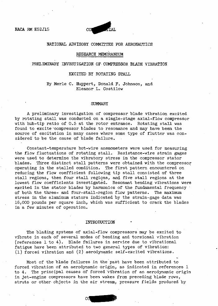
NACA RM E52J15CO **C
NATIONAL ADVISORY COMMITTEE FOR AERONAUTICS
RESEARCH MEMORANDUM
PRELIMINARY INVESTIGATION OF COMPRESSOR BLADE VIBRATION
EXCITED BY ROTATING STALL
By Merle C. Huppert, Donald F. Johnson, and Eleanor L. Costilow
SUMMARY
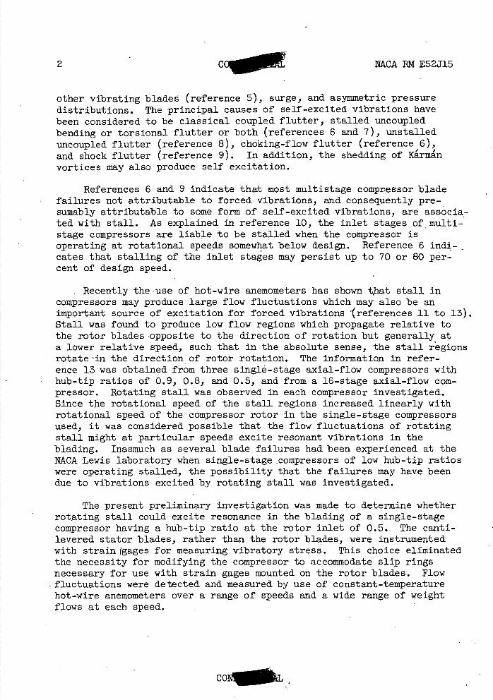
A preliminary investigation of compressor blade vibration excited by rotating stall was conducted on a single-stage axial-flow compressor with hub-tip ratio of 0.5 at the rotor entrance. Rotating stall was found to excite *compressor blades to resonance and may have been the source of excitation in many cases where some type of flutter was con-sidered to be the cause of blade failure.
Constant-temperature hot-wire anemometers were used for measuring the flow fluctuations of rotating stall. Resistance-wire strain gages were used to determine the vibratory stress in the compressor stator blades. Three distinct stall patterns were obtained with the compressor operating in the stalled condition. The first pattern encountered on reducing the flow coefficient following tip stall consisted of three stall regions, then four stall regions, and five stall regions at the lowest flow coefficients investigated. Resonant bending vibrations were excited in the stator blades by harmonics of the fundamental frequency of both the three- and four-stall-region flow patterns. The maximum stress in the aluminum stators indicated by the strain-gage data was 16,000 pounds per square inch, which was sufficient to crack the blades in a few minutes of operation.
INTRODUCTION
The blading systems of axial-flow compressors may be excited to vibrate in each of several modes of bending and torsional vibration (references 1 to 4). Blade failures in service due to vibrational fatigue have been attributed to two general types of vibration: (1) forced vibration and (2) aerodynamic self-excited vibrations.
Most of the blade failures in the past have been attributed to forced vibration of an aerodynamic origin, as indicated in references 1 to 4. The principal causes of forced vibration of an aerodynamic origin in jet-engine compressors have been wakes from preceding blade rows, struts or other objects in the air stream, pressure fields produced by
CL
2 cc NCA RM E52J15
other vibrating blades (reference 5), surge, and asymmetric pressure distributions. The principal causes of self-excited vibrations have been considered to be classical coupled flutter, stalled uncoupled bending or torsional flutter or both (references 6 and 7), unstalled uncoupled flutter (reference 8), choking-flow flutter (reference 6), and shock flutter (reference 9). In addition, the shedding of Krnin vortices may also produce self excitation.
References 6 and 9 indicate that most multistage compressor blade failures not attributable to forced vibrations, and consequently pre-sumably attributable to some form of self-excited vibrations, are associa-ted with stall. As explained in reference 10, the inlet stages of multi-stage compressors are liable to be stalled when the compressor is operating at rotational speeds somewhat below design. Reference 6 indi-cates that stalling of the inlet stages may persist up to 70 or 80 per-cent of design speed.
• Recently the use of hot-wire anemometers has shown that stall in compressors may produce large flow fluctuations which may also be an important source of excitation for forced vibrations (references 11 to 13). Stall was found to produce low flow regions which propagate relative to the rotor blades opposite to the direction of rotation but generally at a lower relative speed, such that in the absolute sense, the stall regions rotate 'in the direction of rotor rotation. The information in refer-ence 13 was obtained from three single-stage axial-flow compressors with hub-tip ratios of 0.9, 0.8, and 0.5, and from a 16-stage axial-flow com-pressor. Rotating stall was observed in each compressor investigated. Since the rotational speed of the stall regions increased linearly with rotational speed of the compressor rotor in the single-stage compressors used, it was considered possible that the flow fluctuations of rotating stall might at particular speeds excite resonant vibrations in the blading. Inasmuch as several blade failures had been experienced at the NACA Lewis laboratory when single-stage compressors of low hub-tip ratios were operating stalled, the possibility that the failures may have been due to vibrations excited by rotating stall was investigated.
The present preliminary investigation was made to determine whether rotating stall could excite resonance in the blading of a single-stage compressor having a hub-tip ratio at the rotor inlet of 0.5. The canti-levered stator blades, rather than the rotor blades, were instrumented with strain (gages for measuring vibratory stress. This choice eliminated the necessity for modifying the compressor to accommodate slip rings necessary for use with strain gages mounted on the rotor blades. Flow
- fluctuations were detected and measured by use of constant-temperature hot-wire anemometers over a range of speeds and a wide range of weight flows at each speed.
C0I'i
NACA RM E52J15 CoN. 3
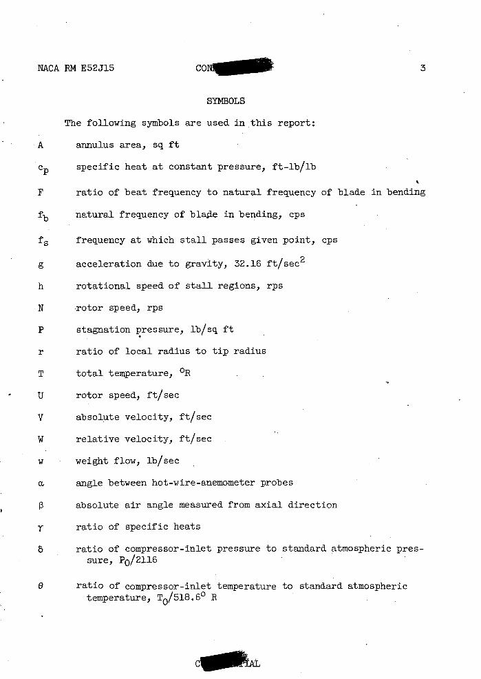
SYMBOLS
The following symbols are used in this report:
• A annulus area, sq ft
c specific heat at constant pressure, ft-lb/lb
F ratio of beat frequency to natural frequency of blade in bending
fb natural frequency of blade in bending, cps
fs frequency at which stall passes given point, cps
g acceleration due to gravity, 32.16 ft/sec2
h rotational speed of stall regions, rps
N rotor speed, rps
P stagnation pressure, lb/sq ft
r ratio of local radius to tip radius
T total temperature, OR
U rotor speed, ft/sec
V absolute velocity, ft/sec
W relative velocity, ft/sec
weight flow, lb/sec
a angle between hot-wire-anemometer probes
0 absolute air angle measured from axial direction
T ratio of specific heats
8 ratio of compressor-inlet pressure to standard atmospheric pres-sure, P0/2116 •
e ratio of compressor-inlet temperature to standard atmospheric temperature, T0/518.60 B
C
4- CO AL NkCA RM E52J15
number of stall regions in annulus
P density, lb/cu ft
PV mass-flow rate, lb/(sec)(sq ±'t)
TV mass-flow rate indicated by average current through hot wire, lb/(sec)(sq ft)
PVav time average mass-flow rate, lb/(sec)(sq ft)
2Y.. amplitude of flow fluctuation divided by pV based on average PV current through hot wire
bladiiig solidity, chord to pitch ratio,
blade-angle setting measured from axial direction, (fig. 1)
CP flow coefficient, IT Ol't
1 2gcT0 (P3
- pressure coefficient, _Ut2
]
Subscripts:
av average
b blade -
s stall
t tip
z axial
0 inlet depression tank
1 between guide vanes and rotor
2 between rotor and stator
3 after stator
COi\I ii
NACA RM E52J15 COI 5
Superscripts:
* indicates quantity has been divided by rotor tip velocity, Ut
APPARATUS AND PROCEDURE
Compressor
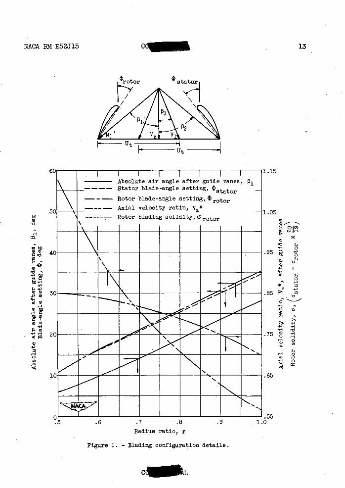
The single-stage compressor used in this investigation consisted of 40 steel inlet guide vanes, 19 steel rotor blades, and 20 cantilevered aluminum stator blades. The stage had a hub-tip ratio at the rotor inlet of 0.5, representative of the inlet stage of a multistage compressor. The guide-vane-discharge angle, the rotor and stator setting angles, the rotor and stator solidity, and the design ratio of axial velocity to rotor tip speed at the outlet of the guide vanes are shown in figure 1.
The guide vanes were variable-chord circular-arc sheet-metal vanes. The rotor and stator blades had NACA 65 series blower blade profile 65(12)-1 at all radii. The chord length was 1.31 inches at all radii for both rotor and stator blades. The stator-blade natural frequency in bending fb was experimentally determined to be 420 cycles per second. The vector diagrams computed from experimental data obtained at approximately the maximum efficiency operating point at the design operating speed are presented in figure 2; for this operating point the flow coefficient Cp is 0.565 and the rotor speed N/4 is 202 rps.
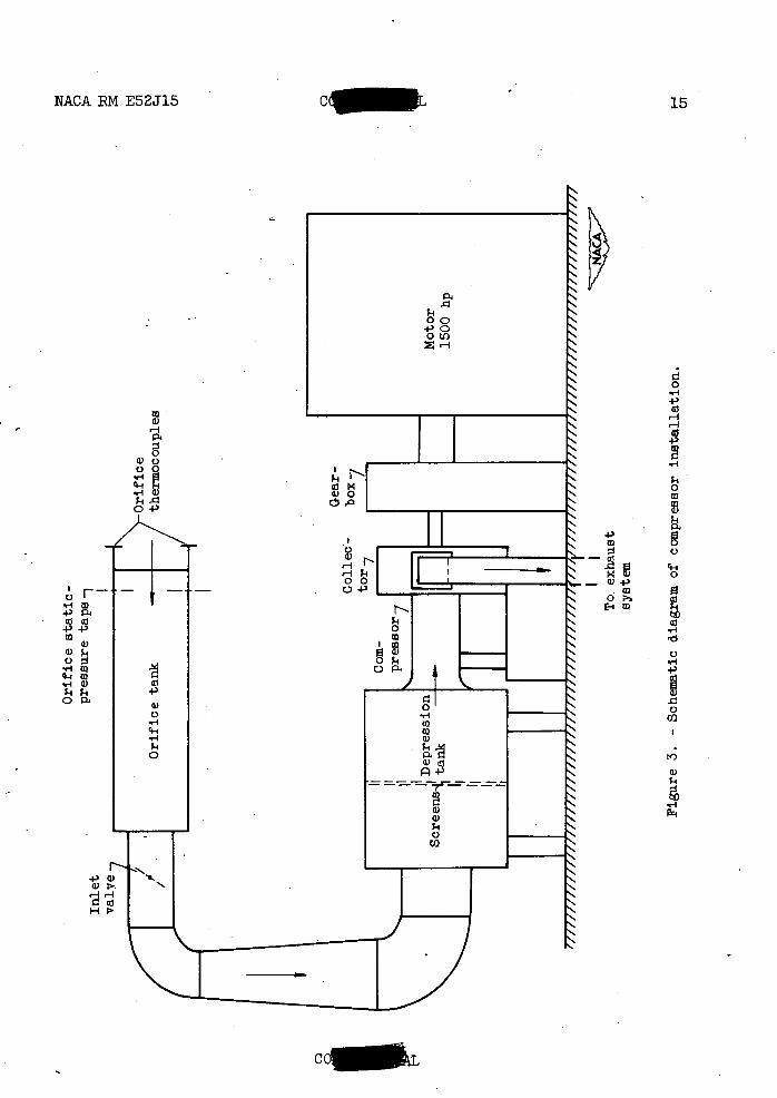
A schematic diagram of the single-stage compressor installation is shown in figure 3. Air enters through the orifice tank and a motor-operated inlet throttle into a depression tank equipped with screens to provide a uniform distribution of air at the compressor inlet. Air was discharged from the compressor into a collector connected to the labora-tory altitude-exhaust system by two outlet pipes. A motor-operated throttle was installed in the outlet pipe. The compressor was driven by a 1500-horsepower variable-frequency motor through a step-up gearbox.
The instrumentation used to obtain over-all performance was similar to that described in reference 14. The instrumentation station locations are shown in figure 4.
Instrumentation for Measuring Flow Fluctuations
The flow fluctuations of rotating stall were detected and measured with constant-temperature hot-wire anemometers. The anemometer probes were made with 0.0002-inch-diameter tungsten wire aM had an effective length of 0.08 inches. The amplifier used is that discussed in refer-ence 15. This feed-back amplifier maintains a constant anemometer-probe resistance and consequently a constant temperature of the hot-wire element during flow fluctuations, providing continuous compensation for lag in hot-wire response.
CO

6 COI AL NACA RN E52J15
Two anemometer probes were installed in radial traversing mechanisms about 1/2 inch downstream of the stators (station 3, fig. 4). One of the anemometer probes was installed in a circumferential survey pad, so that the angle between the two probes could be varied. This provision was necessary to permit the determination of the number of stalls (reference 13).
The anemometer signals were viewed or recorded photographically from a dual-beam cathode-ray oscilloscope. The stall frequency f 5 was obtained by forming Lissajous figures on the oscilloscope by use of an audio-frequency oscillator.
The methods of converting the voltage fluctuations as read from the oscillogra.ms to fluctuations in mass-flow rate zpV/pV and of deter-mining the number of stalled regions in the annulus were those outlined in reference 13.
Strain-Gage Installation on Stators
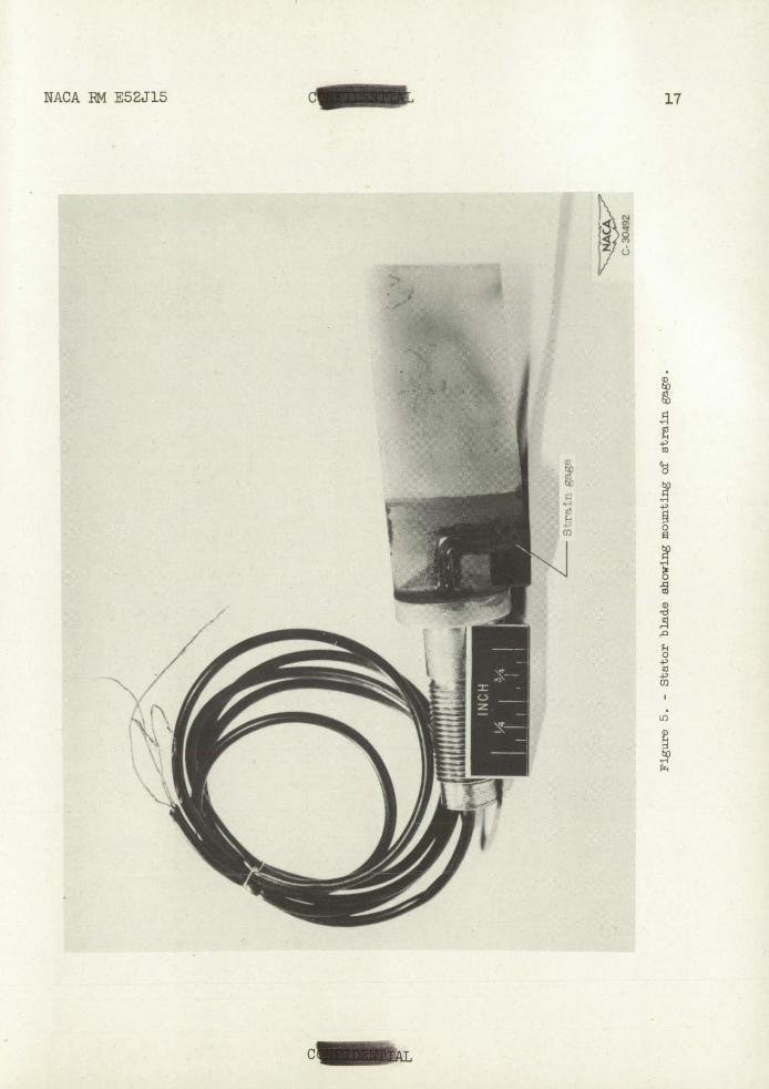
Resistance-wire strain gages were mounted on 3 of the 20 stator blades. _A photograph of a stator blade with the strain gage attached is shown in figure 5. The gages were attached to the blades with Bake-lite cement, with the resistance-wire filaments parallel to the blade span. Gages were installed on both the suction and pressure surfaces at-the blade base near the trailing edge, so that both bending and torsional vibration could be detected. Subsequent bench tests indicated that the ratio of bending stress at midchord to that at-the strain-gage location was 1.35, and this factor was used in computing the bending stress from the strain-gage signals. The strain-gage signals were ampli-fied and recorded photographically or viewed from a four-beam cathode-ray oscilloscope.
RESULTS AND DISCUSSION
In order to determine whether large-amplitude vibratory stresses observed in the stator blades at certain rotational speeds and weight flows could be excited by resonance with the stall frequency f 5 , it was necessary to investigate the stall characteristics of the stage. These stall characteristics will be discussed prior to the discussion of the vibrations excited.
Performance and Stall Characteristics of Compressor
The information presented on the stall characteristics of this single-stage compressor supplements that presented in reference 13, which contains incomplete stall data on a stage with a hub-tip ratio of 0.5.
cor

NACA RN E52J15 CC 7
The performance parameters chosen to represent the performance characteristics of the compressor are flow coefficient cp and pressure coefficient '4r. Figure 6 shows the variation in pressure coefficient jr with flow coefficient cp.
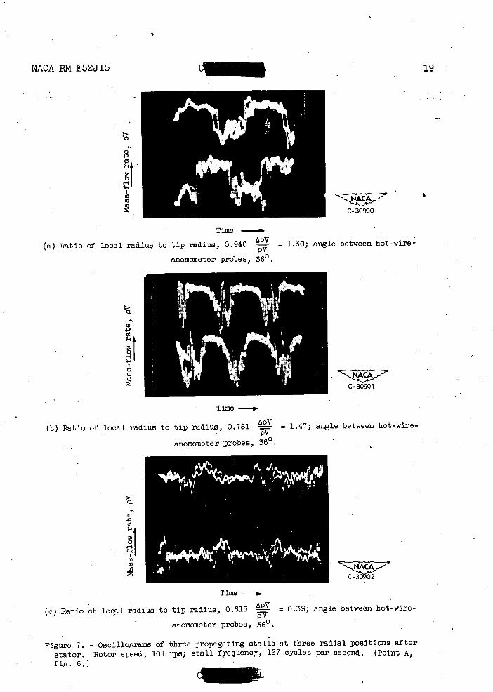
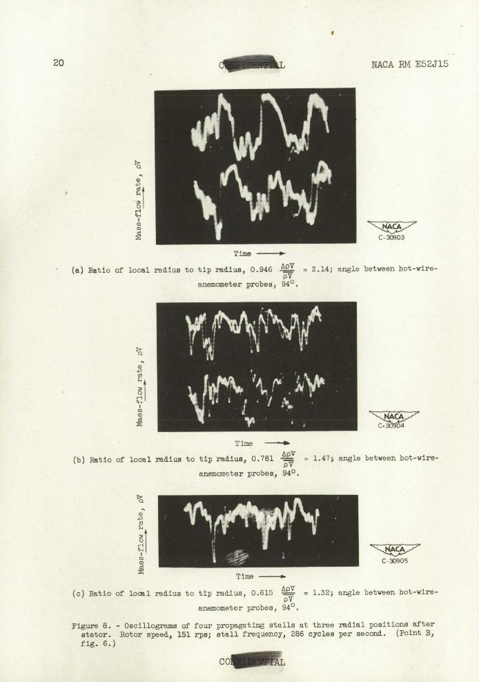
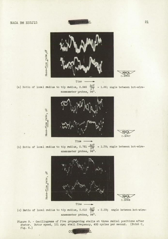
• Rotor tip stall was experienced near the peak value of pressure coefficient. As the flow coefficient was further reduced, rotating stall was detected by the hot-wire anemometers at station 3 (fig. 4). The first rotating-stall pattern obtained when the weight flow was decreased consisted of three equally spaced stall regions rotating in the direction of rotor rotation. Oscillograms of the signals from the two anemometer probes displaced angularly 360 and at three radial posi-tions of the probes are shown in figure 7 (compressor operating at point A, fig. 6). The amplitude of the flow fluctuations varied some-what with radius, as shown. As the flow coefficient was further reduced to point B, figure 6, the number of stall regions changed from three to four. Osclllograms of this stall pattern at three radial positions with an angular separation of the probes of 940 are shown in figure 8. (Only one anemometer signal is shown at the stator root position.) The varia-tion in amplitude of the flow fluctuations with radius is less than that indicated for the pattern with three stall regions, shown in figure 7. As the flow coefficient was reduced to point C (fig. 6), the stall pattern changed. Five or a multiple of five Stalls were indicated. The data obtained were insufficient to distinguish between five and a multi-ple of five stalls, but, inasmuch as there were only 19 rotor blades, the number five seemed the most likely. Consequently, this pattern is considered to consist of five stall regions. Oscillograms of this stall pattern at three radial positions with an angular separation of the probes a. of 940 are shown in figure 9. With this stall pattern the largest flow fluctuations occurred near the hub position.
The following table summarizes the stall information obtained but does not include all data obtained:
Rotational Frequency of Number Rotational h speed of stall region 'of stall speed of compressor passing ane- regions stall
(rps) mometer probe regions h
(cps) (rps)
101 127 3 42.3 0.419 151 191 3 63.7 .422
• 100 190 4 47.5 .475 151 286 4 71.5 .474
- 101- 261 5 52.2 .517 .151 400 5 80 .530
8 IAL NACA RM E52J15
These data indicate that the rotational speed h of the stall regions and consequently their frequency f 5 increase nearly linearly with rotational speed of the compressor rotor. This Is in agreement with the data of reference 13.
The rotational speed of the stall regions with each stall pattern was independent of weight flow at a given rotor speed, and there was neither a marked change in compressor-discharge pressure as the stall pattern changed nor a hysteresis loop associated with stall (refer-ence 13). Audible surge was not detected at any compressor speed.
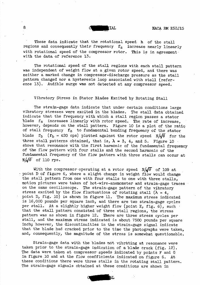
Vibratory Stress in Stator Blades Excited by Rotating Stall
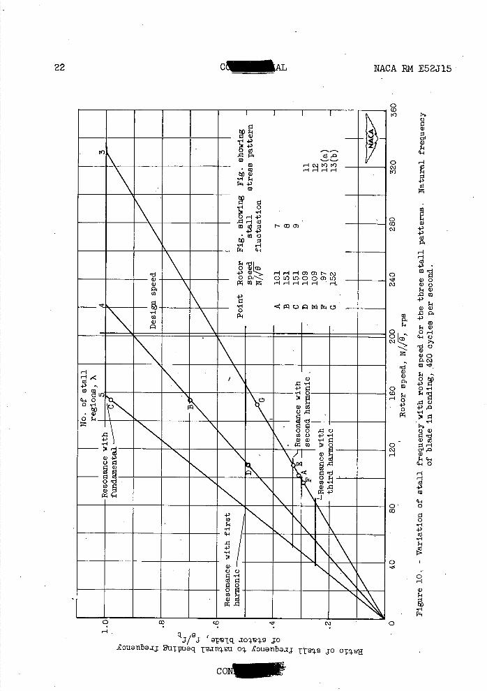
The strain-gage data indicate that under certain conditions large vibratory stresses were excited in the blades. The stall data obtained indicate that the frequency with which a stall region passes a stator blade f5 increases linearly with rotor speed. The rate of increase, - however, depends on the stall pattern. Figure 10 is a plot of the ratio of stall frequency f 5 to fundamental bending frequency of the stator blade fb (fb = 420 cps) plotted against the rotor speed NIAFO for the three stall patterns obtained, that is, ? = 3, 4, and 5. Figure 10 shows that resonance with the first harmonic of the fundamental frequency of the flow pattern with four stalls and the second harmonic of the fundamental frequency of the flow pattern with three stalls can occur at N%1 of 110 rps.
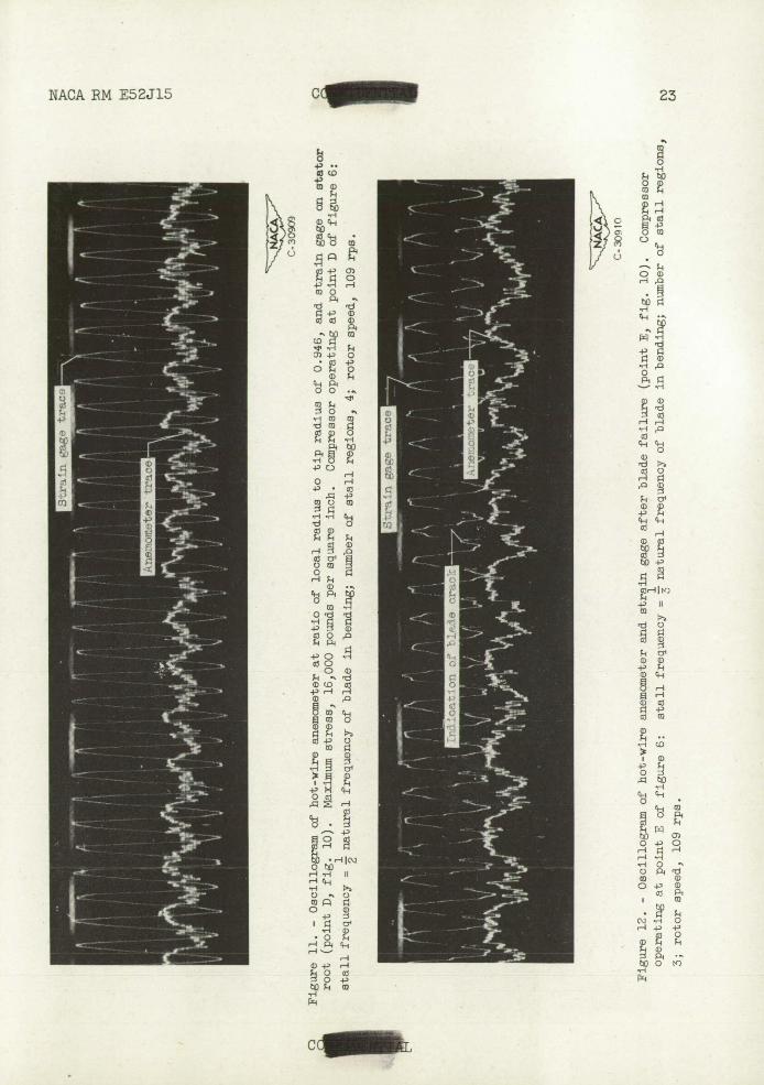
With the compressor operating at a rotor speed N/4 of 109 at point D of figure 6, where a slight change in weight flow would change the stall pattern from one with four stalls to one with three stalls, motion pictures were taken of hot-wire-anemometer and strain-gage traces on the same oscilloscope. The strain-gage pattern of the vibratory stress excited by the flow fluctuations of rotating stall (X = 4, point D, fig. 10).is shown in figure II. The maximum stress indicated is 16,000 pounds per square inch, and there are two strain-gage cycles per stall. At a slightly higher weight flow (point E, fig. 6), such that the stall pattern consisted'of three stall regions, the •stress pattern was as shown in figure 12. There are three stress cycles per stall, and the maximum stress indicated is about 7500 pounds per square inch; however, the discontinuities in the strain-gage signal indicate that the blade had cracked prior to the time the photographs were taken, and, consequently, the magnitude of the stress is somewhat questionable.
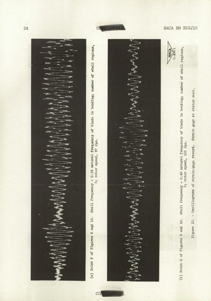
Strain-gage data with the blades not vibrating at resonance were taken prior to the strain-gage indication of a blade crack (fig. 12). The data were , taken at compressor' speeds indicated by points F and G in figure 10 and at, the flow coefficients indicated on figure 6. At these conditions there were three stalls in the rotating stall pattern. The strain-gage signals obtained at these conditions are shown in

NACA RN E52J15 CL 1. 9
figure 13. The "beating" effect is believed to be caused by interaction of the forced vibrations due to the rotating stall and the transient vibrations due. to the rather random variation of the amplitude and wave form of the exciting force. If the exciting force were of constant amplitude and wave form, the transients would be damped and no beating would occur.. From the theory of beating (reference 16) the beat frequency should be approximately equal to the difference between the frequency of the exciting force and natural frequency of the blade. At point F of figure 10, the exciting force was the second harmonic of the stall frequency f5 ; therefore, the beat frequency divided by the natural frequency of the blade in bending F is
3f 5 F = 1 - - = 1 - (3)(0.29)
fb =0.l3
or about eight blade vibration cycles per beat.
At point G of figure 10, the exciting force was the first harmonic of the stall frequency f 5 ; therefore,
F = 1 - 2f 5- = 1 - (2)(0.46) fb
= 0.08
or about 12 blade vibrations per beat. The blade vibrations per beat shown in figure 13 are approximately the same as indicated by theory.
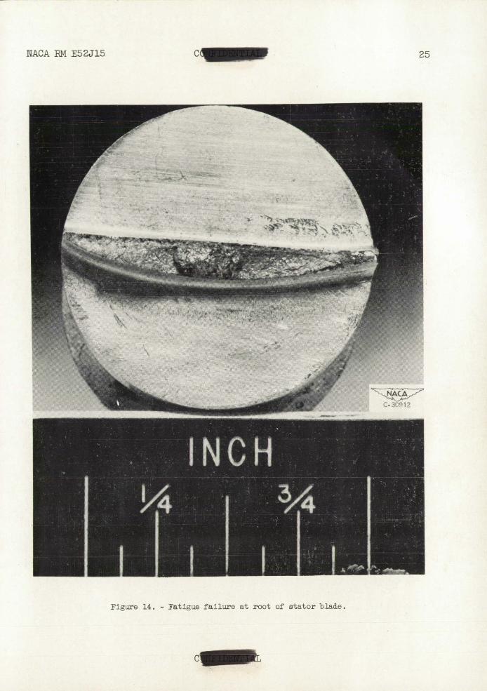
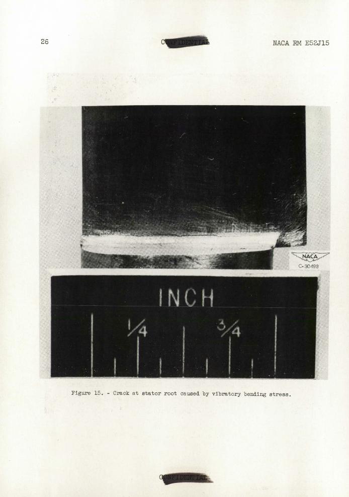
After the strain-gage signals indicated a failed blade, the com-pressor was disassembled for inspection. One stator blade was broken off, and a photograph of the broken end is shown in figure 14. All the stators were cracked in the region of maximum bending stress, as shown in figure 15. The stator blade that broke off damaged the rotor blades by making a notch in the trailing edges near the roots. A crack emanated from the notch in each, rotor blade, in some cases extending to 3/4 chord length.
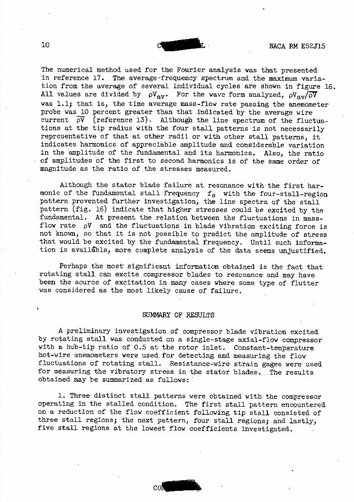
Frequency Spectrum of Flow Fluctuations of Rotating Stall
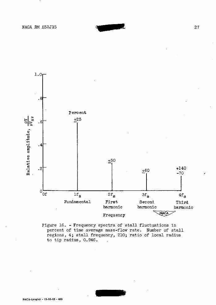
In order to determine the amplitude of the flow fluctuations rela-tive to the average mass-flow rate pVav and to indicate the amplitude of the harmonics 'of the fundamental frequency of the stall fs, a harmonic analysis of the wave form of a stall pattern was made. The oscillograins obtained at the rotor tip radius (r = 0.946) with the stall pattern consisting of four stall regions (point D figs. 6 and 10) were converted by the methods outlined in reference 13 to values of LpV/pV.
CO
10 'T. NACA RN E52J15
The numerical method used for the Fourier analysis was that presented in reference 17. The average-frequency spectrum and the maximum varia-tion from the average of several individual cycles are shown in figure 16. All values are divided by PVav• For the wave form analyzed, PVav/7 was 1.1; that is, the time average mass-flow rate passing the anemometer probe was 10 percent greater than that indicated by the average wire current V (reference 13). Although the line spectrum of the fluctua-tions at the tip radius with the four stall patterns is not necessarily representative of that at other radii , or with other stall patterns, it indicates harmonics of appreciable amplitude and considerable variation in the amplitude of the fundamental and its harmonics. Also, the ratio of amplitudes of the first to second harmonics is of the same order of magnitude as the ratio of the stresses measured.
Although the stator blade failure at resonance with the first har-monic of the fundamental stall frequency f 5 with the four-stall-region pattern prevented further investigation, the line spectra of the stall pattern (fig. 16) indicate that higher stresses could be excited by the fundamental. At present the relation between the fluctuations in mass-flow rate pV and the fluctuations in blade vibration exciting force is not known, so that it is not possible to predict the amplitude of stress that would be excited by the fundamental frequency. Until such informa-tion is available, more complete analysis of the data seems unjustified.
Perhaps the most significant information obtained is the fact that rotating stall can excite compressor blades to resonance and may have been the source of excitation in many cases where some type of flutter was considered as the most likely cause of failure.
SUMMARY OF RESULTS
A preliminary investigation of compressor blade vibration excited by rotating stall was conducted on a single-stage axial-flow compressor with a hub-tip ratio of 0.5 at the rotor inlet. Constant-temperature hot-wire anemometers were used for detecting and measuring the flow fluctuations of rotating stall. Resistance-wire strain gages were used for measuring the vibratory stress in the stator blades. The results obtained may be summarized as follows:
1. Three distinct stall patterns were obtained with the compressor operating in the stalled condition. The first stall pattern encountered on a reduction of the flow coefficient following tip stall consisted of three stall regions; the next pattern, four stall regions; and lastly, five stall regions at the lowest flow coefficients investigated.
cd
NACA EM E52J15 C
11
2. Resonant bending vibrations were excited in the stator blades by harmonics of the fundamental frequency of both the three- and four-stall-region flow patterns. The maximum stress in the aluminum stators indi-cated by the strain-gage data was 16,000 pounds per square inch, which was sufficient to crack the stator blades in a few minutes of operation.
Lewis Flight Propulsion Laboratory National Advisory Committee for Aeronautics
Cleveland, Ohio
REFERENCES
1. Shannon, J. F.: Vibration Problems in Gas Turbines, Centrifugal and Axial Flow Compressors. R. & M. No. 2226, British A. R. C., March 1945.
2. Meyer, Andre J., Jr., and Calvert, Howard F.: Vibration Survey of Blades in 10-Stage Axial-Flow Compressor. I - Static Investigation. NACA RM E8J22, 1949. (Supersedes NACA RM E6J11.)
3. Meyer, Andre' J., Jr., and Calvert,-Howard F.: Vibration Survey of Blades in 10-Stage Axial-Flow Compressor.: II - Dynamic Investiga-tion. NACA RM E8J22a, 1949. (Supersedes MACA EM E7D09.)
4. Meyer, Andre J;, Jr., and Calvert, Howard F.: Vibrat ion Survey of Blades in 10-Stage Axial-Flow Compressor. III - Preliminary Engine Investigation. MACA RM E8J22b, 1949. (Supersedes MACA RN SE8A28.)
5. Forshaw, J. R., Taylor, H., and Chaplin, R.: Alternating Pressures and Blade Stresses in an Axial-Flow Compressor. Rep. No. R. 92, British N.G.T.E., June 1951.
6. Howell, A. R., and Carter, A. D. S.: Note on Stalling Flutter of Compressor Blades. Memo. No. M. 131, British N.G.T.E., Oct. 1951.
7. Mendelson,.Alexander: Effect of Aerodynamic Hysteresis on Critical Flutter Speed at -Stall. NACA RM E8B04, 1948.
8. Bellenot, Ch., and d t Epinay, J. Lalive: Self Induced Vibration of Turbo-Machine'-Blades. The Brown Boveri Review, Oct. 1950, pp. 368-376.
9. Carter, A. D. S., and Kilpatrick, D. A.: Preliminary Flutter Test on a Low Stagger Compressor Cascade. Memo. No. M. 141, British N.G.T.E., Jan. 1952.
C0i
12 . C NACA RM E52J15
10. Finger, Harold B., and Dugan, James F.: Analysis of Stage Matching and Off-Design Performance of Multistage Axial-Flow Compressors. NACA RN E52D07 1 1952.
11. Grant, Howard P.: Hot-Wire Measurements of Stall Propagation and Pulsating Flow in an Axial Flow Inducer-Centrifugal Impeller System. Pratt and Whitney Res. Rep. No. 133, June 1951.
12. Schulze, Wallace M., Erwin, John B., and Westphal, Willard B.: Investigation of an Impulse Axial-Flow Compressor Rotor over a Range of Blade Angles. NACA RM L50F27a, 1950.
13. Huppert, Merle C.: Preliminary Investigation of Flow Fluctuations During Surge and Blade Row Stall in Axial-Flow Compressors. NACA RN E52E28, 1952.
14. Jackson, Robert J.: Effects on Weight-Flow Range and Efficiency of a Typical Axial-Flow Inlet Stage that Result from the Use of a Decreased Blade Camber or Decreased Guide-Vane Turning. NACA RN E52G02, 1952.
15. Ossofsky, Eli: Constant Temperature Operation of the Hot-Wire Anemometer at High Frequency. Rev. Sci. Instr., vol. 19, no. 12, Dec. 1948.
16. Timoshenko, Stephen: Vibration Problems in Engineering. D. Van Nostrand Co., Inc., 2nd ed., 1937. . .
17. Doherty, Robert E., and Keller, Ernest G.: Mathematics of Modern Engineering. Vol. I. John Wiley and Sons, Inc. (New York), 1942.
stator
\ \ rotor
Ut - Ut
1.15
1.05to
00) C'JH
X a)
,-4 0 .95
-'
a)
b
4.' a
Ui0
b .) .85
.' b
4-'
-4.' .,-i
'-' 'd
7Z 0 r4
•' 0 H H
H o
'- 0
.65
NACA P.M E52J15 CC 13
6C
5( tio a) rd
H aJ.
a)a)
Ui
'-4
4.'
CU (D +'W
COG)
Go pq
H a,
H
ala)
-IH
0 4.'
H 0
.6 .7 .8 .9
Radius ratio, r
0 .5
I I I I I I Absolute air angle after guide vanes, Stator blade-angle setting, 0
stator —
\
— - — Rotor blade-angle setting, rotor — --- Axial velocity ratio, V* —
----- Rotor blading Solidity,rotor
I -7'
N— .55 1.0
Figure 1. — Blading configuration details.
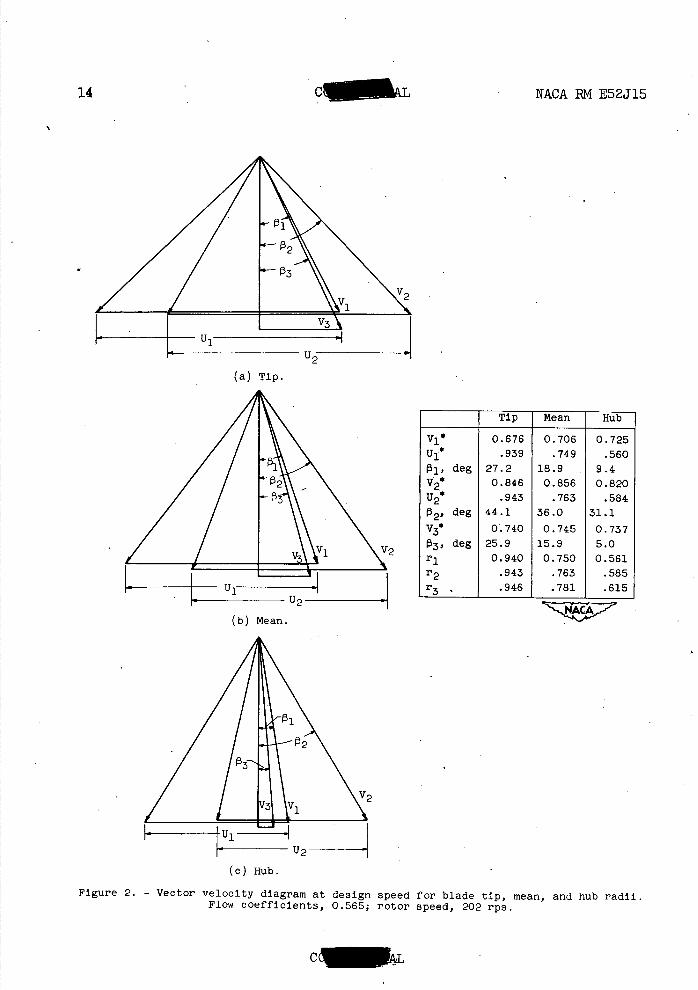
Tip Mean Hub
111 0.676 0.706 0.725 .939 .749 .560
0 1 , deg 27.2 18.9 9.4 V2 0.846 0.856 0.820
.943 .763 .584
2' deg 44.1 36.0 31.1 V3 0.740 0.745 0.737
deg 25.9 15.9 5.0 r1 0.940 0.750 0.561 r2 .943 .763 .585 r3 .946 .781 .615
LI
(a) Tip.
(b) Mean.
2
(c) Hub.
14 ______ NACA BM E52J15
Figure 2. - Vector velocity diagram at design speed for blade tip, mean, and hub radii. Flow coefficients, 0.565; rotor speed, 202 rps.
4) CD
-.
- G)4)
lea o
0
H H •4g
1
0
C)
CH 0
tio
to
Pri
U,
C)
0)
•rI
4.) to
a)
-I a
q-4 )
o
4.)
a)
H
CO_
NACA RM E52J15 C 15

16
C NACA PM E52J15
!srl p l mnnni,rinn atn+lnno
Figure 4. - Sketch showing instrumentation stations.
C
cD
co
0
0
NACA PM E52J15 C - 17
CINEWWAL

0
Q)
0)
co
N-
9-
I K)
c'J
C) a)
4-, to
a) H
C'-4
0
a)
0 •rl 4-' a) 0 0
LU
H 4-i-0 -P4-'
Cd
0) -i-'
CH CH
op I1
a) 0 0 a)
a, U,
ri—I
0
0 '-I -4-' 01
•rI
(0 0)
18
NACA RM E52J15
4
P4 cd -10
Hc'V)V) HHHr-1
I'
4' I I
r1 0 I__
I .1 OH.1-)
10 r-i co
W:j NO)
t•rI H \ rX4 q-4
\ -I OU)I(b -P (1) . r-I r4 H a 0) N- ('-1 0Pf-. Of) LC) 000)LO
HHHHH H
-:-\ CH
cu
LO cz^ to
4\ 'UQT 3TJJ O3 msa.xa
-H cq
C-30900
'-4
S
C. 30901
H
S
NACA C. 30.. 02
tl
4,
H
S
I
NACA PM E52J15
(I
19
(a) Ratio of local radiusto tip radius, 0.946 = 1.30; angle between hot-wire-Pv
anemometer probes, 360.
Time —v
(b) Ratio of local radius to tip radius, 0.781 = 1.47; angle between hot-wire- PV
anemometer probes, 360.
Time -.Pv (c) Ratio of 1ol radius to tip radius, 0.615 = 0.39; angle between hot-wire-
PV anemometer probes, 360.
Figure 7. - Oscillograms of three propagating, stalls at three radial positions alter stator. Rotor speed, 101 rps; stall frequency, 127 cycles per second. (Point A, fig. 6.)
77
C- 30903
a 4)
0 H
Ell tj-
a
H
NACA RM E52J15
Time
(a) Ratio of local radius to tip radius, 0.946 = 2.14; angle between hot-wire-TV
anemometer probes, 940
L !r 0 , • -
8 g j r -
0
a 4)
Cd
H
a
Time
(b) Ratio of local radius to tip radius, 0.781 QPV = 1.47; angle between hot-wire-pV
anemomoter probes, 940
C- 30905
(o) Ratio of local radius to tip radius, 0.615 1.32; angle between hot-wire-pV
anemometer probes, 940
Figure 8. - Oscillograms of four propagating stalls at three radial positions after stator. Rotor speed, 151 rps; stall frequency, 286 cycles per second. (Point B, fig. 6.)
CO.
C- 30c)07
a a) a)
-1
a
C- 30908
Q)
a)
0
a
NACA P.M E52J15 _________ 21
IS
a)
f 0
M
Time
(a) Ratio of local radius to tip radius, 0.946 = 1.66; angle between hot-wire-PV anemometer probes, 940•
(b) Ratio of local radius to tip radius, 0.781 APV = 1.39; angle between hot-wire-anemometer probes, 940•
TimeApv
(c) Patio of local radius to tip radius, 0.615 - = 2.29; angle between hot-wire-anemometer probes, 940•
Figure 9. - Oscillograms of five propagating stalls at three radial positions after stator. Rotor speed, 151 rps; stall frequency, 400 cycles per second. (Point C, fig. 6.)
CC., LL
22 CMININIKU NACA BM E52J15
(0 4')
a) CI U k
o H a)
NO k
a)
I I
--- il 2 HC'J1)tO HHH,-1 a)
'-4k P4 42
\ __
,-1 0 '-4
—Haj
Oa)Icr, V .pQ)H H H0)ON-çj
a)0 P-. 0 It) If) 0 0 0) If) -
HHHHH H
co
_
J - co
-I --—O---------CH 0
Pill\ 0
-U----rl rd
c'J H
.I0q.s Jo ourb.zj 9uTpuaq TlgJn4'gu oq SouanbaaJ jo OTqud
0 k coa) C')
ai P. -1 H a)
o ,4 WO C') O)
1a) .0W 4.)
k a)a) .02.
P4aD
kG) o OH 0I_ eHO C')L
- 0
2.
' 0) o 2.
0,-I (0 k
PI
H.00) '-I
00)
o H C') 01,0 -1 0)
q-IO
H H a) 4.) aD
0 0 co
0 '-4 4.) a)
'-4 k
o I
0 H 0)
1=1 0
coN
'U
0 '-4
0 a) a) a)r4
H-P OW 0
0
Id
-1
a)a)
a) cH-4
0 a)
r4
a) -4-, c,-4l-1
a)'-I
a) a)
a)
Id
co
a) a)
a) C4.4
04'
a) a)
a) a)
a)
aD
a) -P 0
CH 4-1 0
OPi a) 4
(7) 0+'O
r-4 ,-1
0 Pi'd a) a) 0+' a)
a)p4
-P -P 0
a)4 4 4a)
to C') 4'
1i
NACA EM E52J15 Cc 23
4,.. 4.'
rl
\;
Va0
P4 d 'd
-P a) a) a) a)
P, -ta) a)
J)4- 0 • a) 0 0
00..
- ,-4 a) a) 'da) 1
P4 w
a)a) 0 4'
P4
4' C)'-4
o• a)
a)0 aj
'd 0 -1
a) a)
OW o
a)
a) H O'd 'd -i
4' a)
4'0 4'
0 a)
a) (O a) 4' 4' a) ,a
H a) 0
a)4.' a
a) a) a
- C44
4'
0 • a) -P HO
ijr4
0a) r4 4' o o
o a) -P a)
,-1 a) •o
'-4'-4
a)-P r-4 a)
004' 0
'-4
cc
H H a)
a)
0
a)
I'
a)
0
0
0
4-1 LO
-4
43a)
(O
• 4' 00
0
a) 0
a)
-4 H co
-4.' CO
I 0 H
a)
C-Cl
a) a)
C-,
.4-, H 0
PA
4' 0
0 4,
a)
4' cc
H
Cl]
0 C)
a)
a)
H I
24 c NACA RM E52J15
0
a) 0
a)
Cl)
0 r-
Id
a)
a)
0
H
a)
Col
NACA RM E52J15 C. 25
I
Figure 14. - Fatigue failure at root of stator blade.
C
'NACA RM E52J15
mow 3O93
FL.re Ji. - Cra:k 't stator root o3ed oy vibratory bendin stress.
i.r
C1.. a)
•1-4
4o D
NACA PM E52J15 C 1T. 27
Of ifs 2f8 3f8 4f
Fundamental First Second Third harmonic harmonic harmonic
Frequency
Figure 16. - Frequency spectra of stall fluctuations in percent of time average mass-flow rate. Number of stall regions, 4; stall frequency, 210; ratio of local radius to tip radius, 0.946.
NACA-Langley - 12-18-52 - 450

'I'll, M11% 0.111,17 11. 1
Pon