Embed Size (px)
Citation preview
. I
RESEARCH MEMORANDUM
ANALYSIS OF EFFICIENCY CHARACTERISTICS OF A SLNGLE-STAGE
TURBINE WITH DOWNSTREAM STATORS IN TERMS OF
WORK AND SPEED REQUIREMENTS
By William T. Wintucky and Warner L. Stewart
Lewis Flight Propulsion Laboratory Cleveland, Ohio
LIBRARY COPY
NATIONAL ADVISORY COMMITTEE FOR AERONAUTICS
WASHINGTON January 23, 1957
. .
I
I
https://ntrs.nasa.gov/search.jsp?R=19930090212 2018-06-09T16:56:33+00:00Z
NACA RM E56J19
NATIONAL ADVISORY C O l 4 " E E FOR AEXIOIXAUTICS
t
13 -I e c
RESEARCH MEMORANDUM
ANALYSIS OF EFFICIENCY CHARACTERISTICS OF A SINGLE-STAGE TURBINE
WITH DOWNS- STATORS IN TERMS OF WORK AND SPEED REQUlREMENTs
By William T. Wintucky and Warner L. Stewart
S W Y
The efficiency characterist ics of a single-stage turbine with down- stream s t a to r s a r e analyzed; It is assumed that the mean-section flow is one-dimensional and tha t the b lade spec i f ic losses a re p ropor t iona l to the average specific kinetic energy. The eff ic iencies are presented i n terms of a work-speed parameter X, defined as the r a t io of the square of the mean-section blade speed to the required specif ic work output. R a n g e of t h f s parameter of 0 t o 0.5 is tha t appl icable in c r i t i ca l tu rboje t en- gines as w e l l as i n turbopumps and accessory drives. The eff ic iencies investigated are t o t a l o r aerodynamic, rating, and s t a t i c . Impulse and
these two types are compared with that of the single-stage i m p u l s e veloc- i t y diagram, since this case yielded higher rating and s t a t i c e f f i c i enc ie s for t h e reaction limit imposed on the rotor . The downstream stator load- ing is limited by a suction-surface diffusion factor of 0.5.
r;' d
v maxim-efficiency velocity diagrams are considered. The efficfencies of
Below X of 0.38 the r a t ing and s t a t i c e f f i c i enc ie s can be increased by the addition of downstrem stators. With one s ta tor , the maxim- efficiency velocity diagram reaches the diffusion limit of 0.5 first f o r zero turbine exit whirl at X of 0.29, whereas the impulse velocity dia- gram reaches t h i s l i m i t at x of 0.205. By the addition of a second downstream s ta tor , the impulse case reaches limiting diffusion at x of 0.095. A f t e r the diffusion l i m i t is reached, it is necessary t o impose progressively more turbine e x i t whirl i n order not t o exceed the dfffusion limit as h is reduced. With one downstream s ta tor , up t o about 16 points increase in rating efYiciency and 1 2 ~ poin ts increase in s ta t ic efficiency can be obtained, depending on the region of h. With two down- stream stators, about 24 points increase in ra t ing eff ic iency and 20 points increase i n s ta t ic e f f ic iency are possible, depending on the region of x.
1
CI
INTRODUCTION 51
Analytical studies to determine the effect of variations in work and speed requirements on over-all turbine efficiency are currently underway
I
I ! I
I I
I
I
I
I
I
I
2 MACA RM E56Jl9 - at the NACA L e w i s laboratory. The fundamental parameter used i s "Parson's characteristic number" (ref. l), which is defined as the r a t i o . I
of the square of' the mean-section blade speed t o the specific work output for design conditions.
In reference 2, single-stage turbine efficiency was determined f o r 8 range of the work-speed parameter h from 0 t o 1.0, which is applicable t o J e t engines as w e l l a8 turbopurqps and accessory bives . Resul ts of t h i s analysis indicate that, i n the range of X from 0 t o 0.5, turbine IP eff ic iencies are considerably decreased as a re su l t of (1) increased z. viscous losses due to the Increased f l o w velocities required for a given U I '
work output and (2) high turbine exi t k inet ic energy required t o prevent negative reaction across the turbine. Most of t h i s k ine t i c energy i s In terms of ex i t whirl.
t
One mean6 of-improving the eff ic iency of turbines in the lower range of work-speed parameter ( X of 0 t o 0.5) i s using stators downstream of the turbine, These s ta tors tu rn the f l o w out of t he rotor back towwd the axial direction and thus reduce the whirl losses out of the turbine. Net.improvement in eff ic iency can be realized, i f the reduction I n exit= whirl losses more than compensates for the additional viscous losses due t o t h e added s ta tors .
This ana lp i s eva lua te s t he e f f ec to fadd ing downstream s ta tors on turbine efficiencies based on the work-speed parameter X. The range of X from 0 t o 0.5 covered in the analysis is for c r i t i ca l . j e t -engine ap- plications and f o r turbopumps and accessory drives, where low t o moderate blade speeds a re used. with high specific work outputs. The single-stage turbine with downstream s ta tors of this analysis i s hereinafter referred t o as a "1-stage turbine." 1
2
A s in reference 2, three types of efficiency are considered:
(1) Total, o r aerodynamic, efficiency, which includes all aerody- namic losses
(2) R a t i n g efficiency, which, i n aad i t i on t o aerodynamic losses, considers turbine ex i t whir l 8 loss (used i n jet-engine analysie)
(3) Static efficiency, which, i n addition t o aerodynamic losses, considers turbine exit total velocity head R lose (used for turbo- pumps and turbine accessory drives)
These efficiencies are presented for impulse~and~ma&~-efficlency mean- section velocity diagrams. . .
4
W '
.I . "
NACA RM E56J19 3
Efficiency Equations
The total , ra t ing, and static eff ic iencies are developed i n terms of the work-speed parameter h and the upstream-stator exit-whirl param- e t e r V&/AVU, which determines the velocity diagram t o be used. (All symbols are defined in appendix A.) The parameter X is defined
U2 x=- gJahr I
where A h 1 is the actual specif ic work output. The following equations for e f f ic ienc ies are developed for turbines with one downstream s ta tor .
I Total efficiency. - The total efficiency includes al l aerodynirmic losses:
! where Ahld is the ideal specif ic work output corresponding t o t h e
w total-pressure ratio across the turbine. The expression (Ahid - a h r ) is the loss i n spec i f i c energy across the turbine and is introduced into equation (2) as
I
!
Using the general equation relating speed, and change in absolu te w h i r l
the specif ic work output, blade velocity, and solving for U give
(4 1
f o r U and solving for A h 1
( 5 4
U =
Substituting equation (4) into equation (1) yie ld
X(AVJ Ah' - gJ
I
y Combining equations (1) and (4) a l s o yields
I X = - U *VU
I
4 - NACA RM E56J19
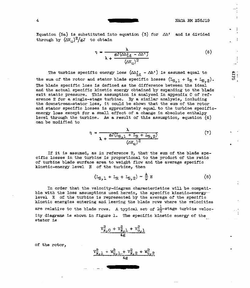
Equation (sa> is substi tuted into equation (3) f o r Ah' and i s divided through by (AVUI2/gJ t o obtain
The turbine specific energy loss (Ahid - A h t ) i s assumed equal t o the sum o f . t he ro tor and s t a to r blade specif ic losses (k,l f $ + k,2). The blade specif ic loss i s defined as the difference between the idea l and the actual specific kinetic energy obtained by expanding to the blade exit static pressure. This assumption is analyzed i n appendix C of ref- erence 2 for a single-stage turbine. By a similar analyais, including the downstream-stator lose, it could be shown thak the sum of the ro to r and s ta tor spec i f ic losses is approximately equ-o the t u r b i n e specific- energy loss except for a small effect of a change in absolute enthalpy level through the turbine. As a r e su l t of t h i s assumption, equation (6) can be modified t o
- t I
!
If it is assumed, as in reference 2, that- the sum of the blade spe- c i f ic losses in the tu rb ine . i s proportional t o t he product of t he r a t i o of turbine blade- surface area t o w e i g h t f low and the average specific kinetic-energy level E of the turbine, then
(Ls,1+ LR + Ls,2) - kE w (81
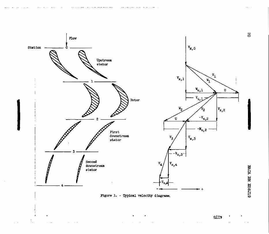
In order that the velocity-diagram chazacteristics will be compati- b l e with the loss assumptions used herein, the specific kinetic-energy" l eve l E of the turbine i s represented by the average of the spec i f ic kinetic energies entering and leaving the blade r o w where the veloci t ies
are relative t-o t h e blade rows. A typical set of l p t a g € ? t u r b i n e veloc- i t y diagrams is shown i n f i g u r e 1. The specific kinetic energy o f the s t a t o r i s
1
"
of t he rotor,
NACA RM E56J19 - 5 I ..
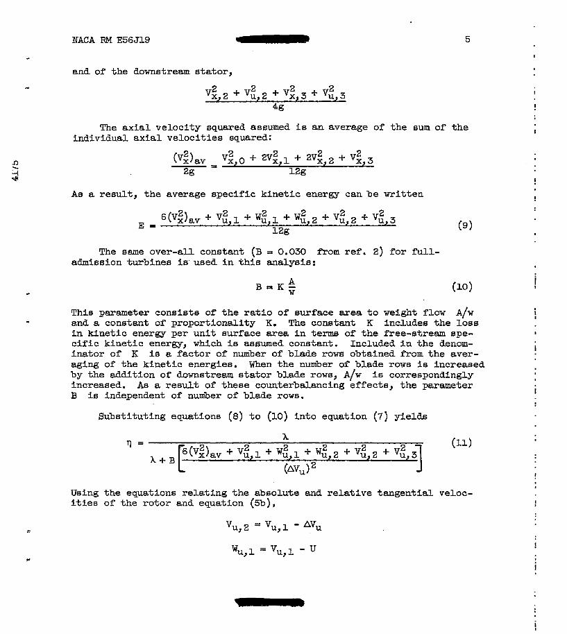
and of the downstream stator , m
The ax ia l ve loc i ty squared assumed i s an average of the Bum of the individual axial veloci t ies squared:
! As a result, the average specific kinetic energy can be wri t ten !
The same over-all constant (B = 0.030 from ref. 2) f o r f'ull- admission turbines is'used in t h i s ana lys i s :
B = K y A c
This parameter consists of t h e r a t i o of surface area t o veight flow A/w
i n k ine t i c energy per unit surface area i n terms of the free-stream spe- c i f i c k i n e t i c energy, which is assumed constant. Included i n t h e denom- inator of K i s a fac tor of number of blade rows obtained from t he aver- aging of the kinetic energies. When the number of blade rows is increased by the addition of downstream stator blade rowB, A/w i s correspondingly increased. As a r e s u l t of these counterbalancing effects, the parameter B i s independent of number of blade rows.
- and a constant of proportionali ty K. The constant K includes the loss
Substituting equations (8) t o (10) into equation (7) yields
I
I
!
L J
Using the equations relating the absolute and relative tangential veloc- i t ies of the rotor and equation (5b),
!
!
6 NACA ,SM E56J19
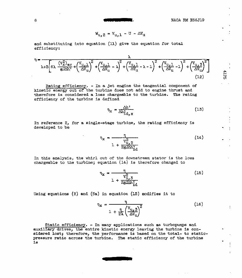
Wu, 2 = Vu,l - U - AV, and substi tuting into equation (ll) give the equation for total efficiency:
Rating efficiency. - kinet ic energy out o f - the theref ore i s ~ considered a efficiency of the turbine
In a j e t engine the tangentid. component of turbine does not add t o engine thrust and loss chargeable t o the turbine. The rat ing is defined
In reference 2, for a single-stage turbine, the rating efficiency is developed t o be
In this analysis, chargeable to the
'1x =I
n
the whi r l out of the downstream s t a to r i s the loss turbine; equation (14.) i s therefore changed t o
Using equations (2) and (5.) i n
vx =
equation (E) modifies it t o
I
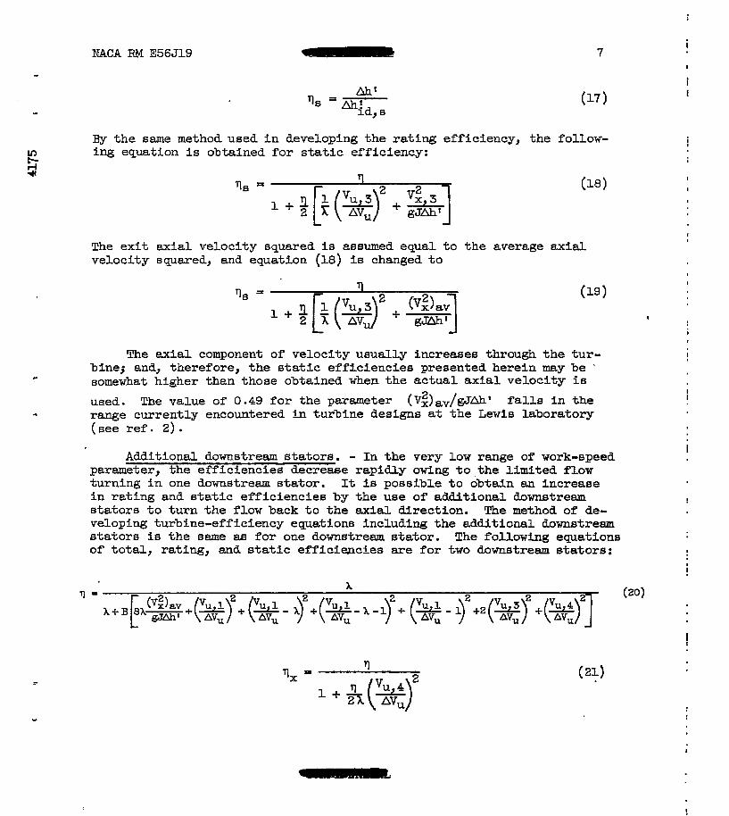
Static efficiency. - In many appUcations such 88 turbopumps and auxiliazy d r ives , the e n t i r e k h e t i c energy leaving the turbine is con- - sidered losti therefore, the performance is based on the to t a l - to s t a t i c - pressure ratio acroes the turbine. The static efficiency of the turbine l e L
NACA RM E56J19 - 7
By the same method used i n developing the rating efficiency, the follow- In ing equation is obtained for static efficiency:
The exit axial velocity squared is assumed equal t o t h e average ax ia l velocity squared, and equation (18) is changed t o
The axial component of velocity usually increases thra.@ the tur- bine3 and, therefore, the s ta t ic eff ic iencies presented herein may be '
somewhat higher than those obtained when the actual axial veloci ty i s
used. The value of 0.49 f o r the parameter (VZ) av/gJbh' falls i n the
( see ref. 2) .
c
.I range currently encountered in turbine designs st the Lewis laboratory
Additional downstream s ta tors . - I n the very l o w range of work-speed parameter, the efficiencies decrease rapidly owing to - the l imi ted f low tu rn ing i n one dawnstream s ta tor . It is possible t o obtain an increase in r a t ing and s t a t i c e f f i c i enc le s by the use of additional downstream s t a to r s to turn the f low back t o t h e axial direction. The method of de- veloping turbine-efficiency equations including the additional downstream s t a to r s is the same 88 f o r one downstream s ta tor . The following equations of total , ra t ing, and static eff ic iencies are f o r two downatream s ta tors :
I
I
i I
I
I
I
I
I
I
I
I
I I
I
!
Ir,
I
8
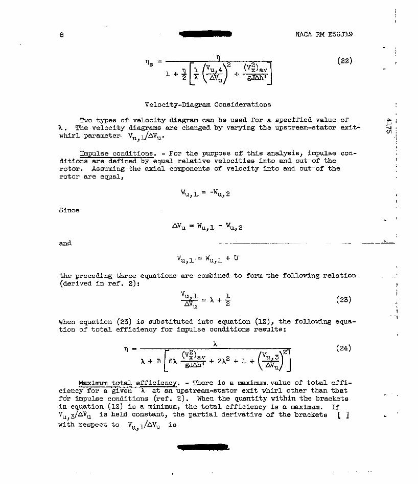
Velocity-Diagram Considerations
Two types of' velocity diamam can be used f o r a specified value of' X . The-velocity diagrams are changed by varying the upstrem-stator exit- whirl parameter- V l/AVu. u,
Impulse conditions. - For the purpose of: this analysis, impulse con- di t ions are defined by equal re la t ive veloci t ies into and ou-Gof the rotor . Assuming the axial components of veloci ty into and outrof t h e rotor are equal,
Since
the preceMng three equations are combined (derived i n ref. 2) :
U
t o form the following relation . ..
! I
(23) I
When equation (23) is substi tuted into equation (12), the following equa- t i o n of t o t a l - e f f i c i e n c y f o r impulse conditions results:
. . I
I
x
M a x i m to ta l e f f ic iency . - There is a raaximm-value of t o t a l eff i - ciency for a given X at an upstream-stator exit whirl other than that Fo> impulse conditions (ref. 2 ) . When the quantity within the brackets i n e uation ( 1 2 ) i s a minimum, the total eff ic iency is a maximum. If Vu,37AVu is held constant , the par t ia l der ivat ive of the brackets [ w i t h respec t to Vu,l/AVu i s
I
!
NACA RM E56Jl.9 - 9
!
!
I
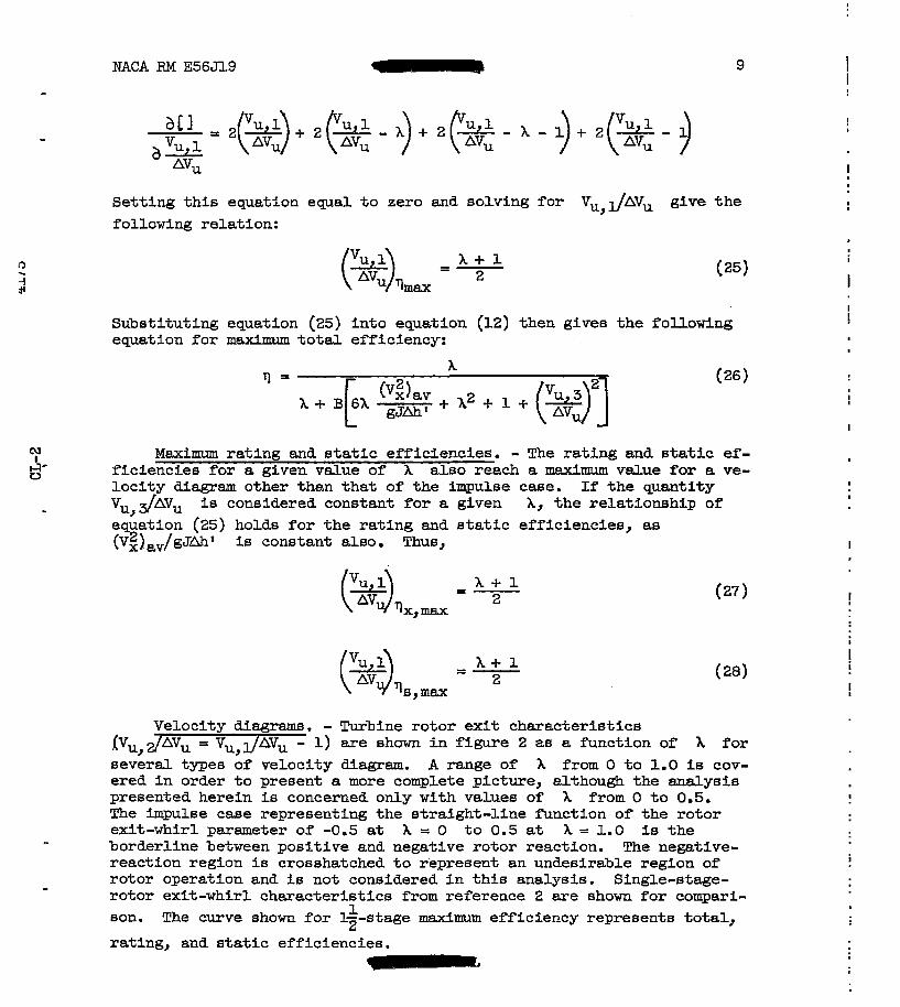
Sett ing this equat ion equal to zero and solving for Vu,JAVu give the following relation:
I
,
Substituting equation (25) into equation (12) then gives the following equation for maximum to ta l e f f ic iency:
I
Maximum ra t ing and static efficiencies. - The rating and static ef- f ic ienc ies for a given value of X also reach a maximum value for a ve- l oc i ty diagram other than that of the impulse case. If the quantity
- Vu,dAVu is considered constant for a given X, the re la t ionshfp of equation (25) holds for the ra t ing and s ta t ic e f f ic ienc ies , as (VgI)av/gJAhT is constant also. Thus, I
!
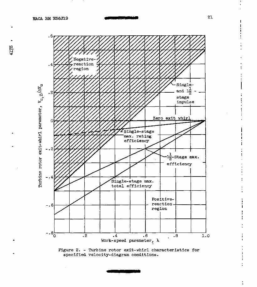
- Turbine rotor exit character is t ics 1) are shown i n figure 2 as a function of
Velocity diagrams. (Vu, Z/AVu = Vu, l/AVu - X f o r s e v e r a l types of velocity diagram. A range of X from 0 to 1.0 fs cov- ered i n order to present a more complete picture, although the analysis presented herein is concerned on ly w i t h values of X from 0 t o 0.5. The impulse case representing the straight-l ine function of the ro tor exit-whirl parameter of -0.5 at X = 0 t o 0.5 at X = 1.0 is the borderline between posi t ive and negative rotor reaction. The negative- reaction region is crosshatched t o represent a n undesirable region of rotor operation and i s not considered i n t h i s analysis. Single-stage- rotor exit-whirl characterist ics from reference 2 are shown f o r compari- son. The curve shown f o r 1--stage maximum efficiency represents total ,
rating, and s ta t ic e f f ic ienc ies .
-
- 1 2
7
10
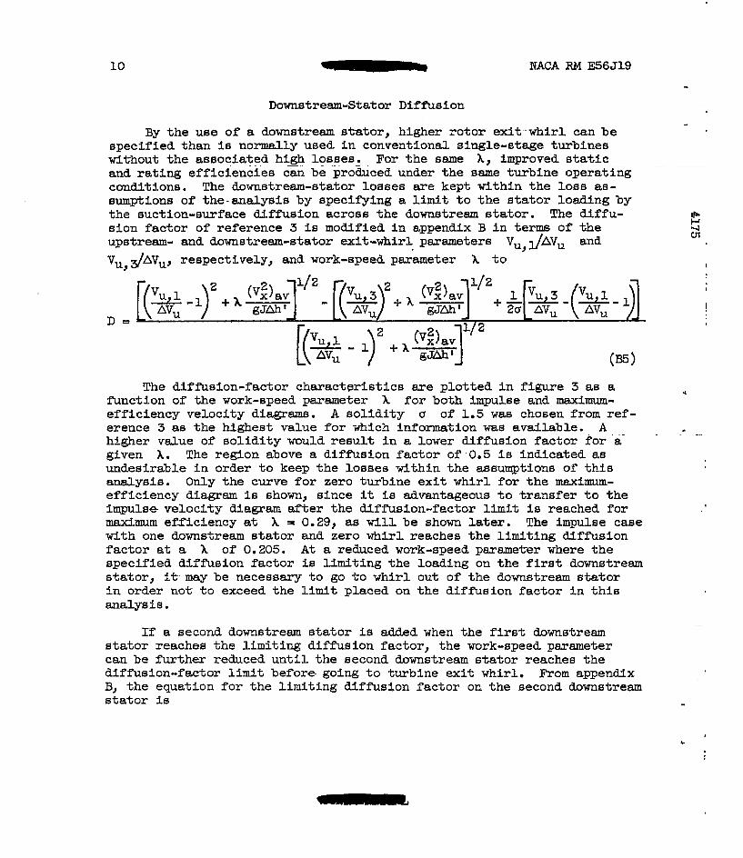
Downstream-Stator Diffusion
NACA RM E56J19
By the use of a downstream s ta tor , higher ro tor exit-whirl can be specified than is normally used in conventional single-stage turbines without the associated high - . . losses. . . . . For t he same h , improved s t a t i c and rating eff ic iencies can be produced under t h e same turbine operating -
conditions. The downstream-stator losses are kept within the lOS6 88- sumptions of the-analysis by specifying a limit- t o the s t a t o r l o a n @ ; by the suction-surface diffusion across the downstream s ta tor . The diffu- sion factor of reference 3 is modified i n appendix B i n terms of the upstream- and downstrem-stator exit-whirl parameters Vu, JAVU and VU,dAVu, respectively, and work-speed parameter X t o
"_ . . . . . . . . . . " - - . . . .
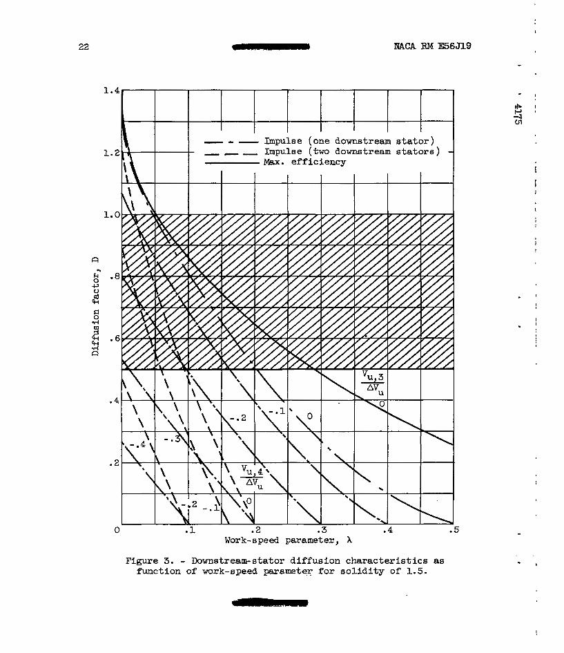
The diffusion-factor characterist ics are p l o t t e d i n figure 3 as a function of the work-speed parameter X for both impulse and maximum- eff ic iency veloci ty diagram. A so l id i ty u of 1.5 w a s chosen from ref- erence 3 as t he highest value for which Information was available. A higher value of so l id i ty would result i n a lower d i f fus ion fac tor for .& given X. The region above a di f f ie ion fac tor o f - 0 . 5 is indicated as undesirable in order to keep the losses within the assuqt ions of t h i s analysis. Only the curve for zero turbine exit w h i r l f o r the maximum- efficiency diagram is shown, since it is advantageous t o t r a n s f e r to t h e impulse velocity diagram &fter the diffusion-factor l i m i t i s reached for m a x i m u m efficiency at X = 0.29, a6 will be shown later. The impulse case with one downstream stator and zero whirl reaches the l imiting diffusion fac tor at a X of 0.205. A t a reduced work-speed parameter where the specified diff 'usion factor is l imit ing the loading on the first downstream s ta tor , i t -may be necessary t o go t o whirl out of t he downstream s t a t o r i n order not t o exceed the limit placed on t h e diffusion factor i n th is =dyS 16.
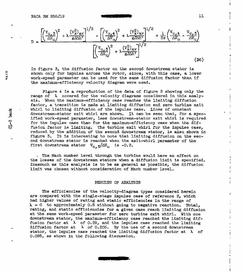
2 3 a second downstream s t a t o r i s added when the first downstream s t a t o r reaches the l imit ing diffusion factor , the work-speed parameter can be further reduced unti l the second downstream stator reaches the diffusion-factor limit before- going to t u rb ine ex i t whirl. From appendix B, the equation for t he l imiting diff 'usion factor on the second downstream s t a to r i s
I
!
.I
. . ..
c
I
NACA FiM E563l9 - 11
In f igure 3, the diffusion factor on the second downstream s ta to r is shown only for impulse across the rotor, since, with this case, a lower work-speed parameter can be used for the same diffusion factor than if the maximum-efficiency velocity dfagram were used.
!
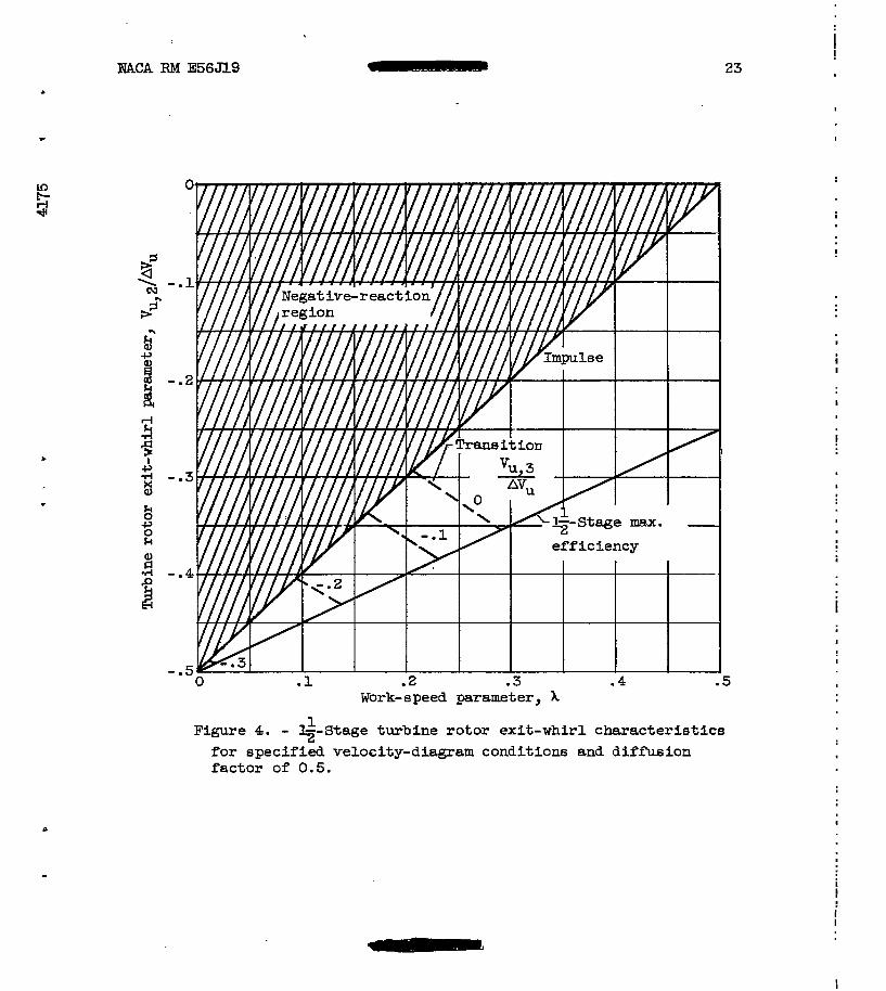
Figure 4 is a reproduction of t he data of f igure 2 showing only t h e I
range of X covered for the ve loc i ty diagrams considered in t h i s ana ly - I
sis. When the maxfmum-efficiency case reaches the limiting diffusion factor, a t r ans i t i on is made at limiting diff 'usion and zero turbine exi t
downstream-stator exi t whir l are shown. It can be seen that, f o r a spec- i f i e d work-speed parameter, less downstream-stator exit whirl is required f o r t h e impulse case than for the maximum-efficiency case when the d i f - fusion factor is limiting. The turbine exi t whir l for the impulse case, L
reduced by the addition of the second downstream stator , is also, shown i n figure 3. It is interest ing to note that limiting diffusion on the sec- ond downstream s t a t o r i s reached when the exit-whirl parameter of the first downstream s t a t o r Vu, dAVu is -0.2.
. whirl to l imit ing diffusion of the impulse case. Lines of constant . . I
03
& -
. The Mach number level through the turbine would have an ef fec t on the losses of the downstream s t a to r s when a diffusion l imit is specified. Inasmuch as th is ana lys i s i s t o b e as general as possible, the diffusion limit was chosen without consideration of Mach number level.
RESULTS OF ANALYSIS
The eff ic iencies of the velocity-diagram types considered herein are compared with the single-stage impulse case of reference 2, which had higher values of rating and s t a t i c e f f i c i e n c i e s i n t h e r a n g e of X = 0 t o approximately 0.5 without going to negative reaction. Total, ra t ing, and s ta t ic eff ic iencies for a gfven case reach l imiting diffusion at the same work-speed parameter f o r zero turbine exit whirl. With one downstream stator , the maximum-efficiency case reached the limiting dif- fusion factor at h of 0.29, and the impulse case reached the limiting
s ta tor , the impulse case reached the l im€ting diffusion factor at h of 0.095, as shown in the following discussion.
- diffusion factor at x of 0.205. By the use of a second downstream
-
I
I
!
I
!
I
12
Total Efficiency
NACA RM E56J19
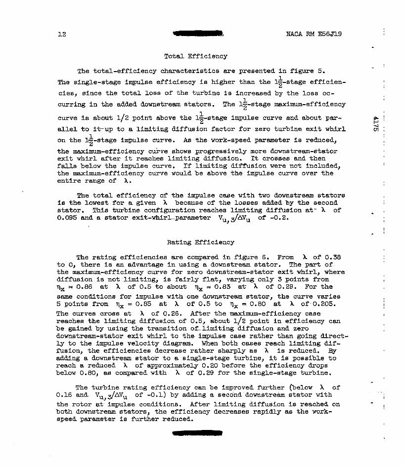
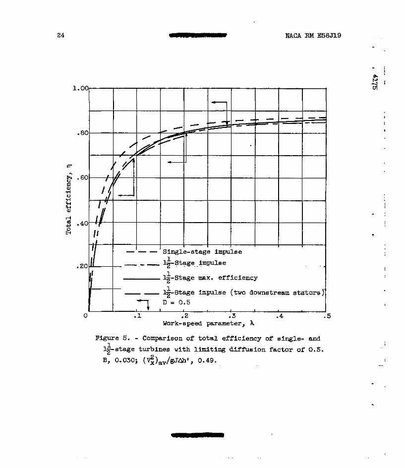
The total-efficiency characterist ics are presented in figure 5.
The single-stage impulse efficiency is higher than the 12-stage efficien- cies, since the t o t a l l o s s of the turbine is increased by the loss oc-
curring f n the added downstream stators . The 12-stage maximum-efficiency
curve i s about 1/2 point above the lz-stage imgulse curve and about par- 1
a l le l t o i t u p t o a l imiting diffusion factor for zero turbine exit whirl on the 1--stage impulse curve. As the work-speed parameter is reduced, the maximum-efficiency curve shows progressively more downstream-stator ex i t w h i r l after it reaches limiting diffusion. It crosses and then falls below the impulse curve. If l imit ing diff is ion were not included, the maximum-efficiency curve would be above the impulse curve over t h e en t i r e range of X.
1
1
1 2
The to ta l e f f ic iency of the impulse case with two downstream s ta to r s is the lowest for a given X because of the losses added by the second s ta tor . This turbine configuration reaches limiting diffusion at- X of 0.095 and a stator exit-whirlparameter Vu, dAVU of -0.2.
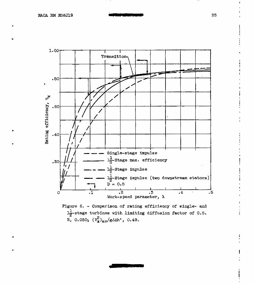
Raking ETficiency
The rat ing eff ic iencies are compared in Ngure 6. From X of 0.38 t o 0, there is an advantage i n using a downstream s ta tor . The par t o r the maximum-efficiency curve for zero downstream-stator exit whirl, where diffusion is not-l imiting, i s f a i r l y f lat , varying on ly 3 points from qx = 0.86 at X of 0.5 t o about qx = 0.83 a t A of 0.29. For the s8me conditions for impulse w i t h one downstream stator , the curve varies 5 points from qx = 0.85 a t X of' 0.5 t o qx = 0.80 at X of-0.205, The curves cross at X of 0.26. After the maxim-efficiency case reaches the limiting diffusion of 0.5, about 1/2 point in efficiency can be gained by using the transit ion oflimiting diffusion and zero downstream-stator exit whirl t o t h e impulse case rather than going d i rec t - l y t o t h e impulse velocity diagram. When both cases reach l imithg dif- Fusion, the efficiencies decrease rather sharply as X is reduced. By adding a downstream s t a t o r t o a single-stage turbine, it is poss ib le to reach a reduced X of approximately 0.20 before the efficiency drops below 0.80, 88 compared with X of 0.29 fo r the single-stage turbine.
The turbine rating efficiency can be improved f u r t h e r (below X of 0.16 and Vu, dAVu of -0.1) by adding a second downstream s t a to r wi th the rotor at-- impulse conditions. After limiting diffusion is reached on both downstream stators, the efficiency decreases rapidly a8 the work- speed parameter i s fur ther reduced.
L
I
I
14
SUMMARY OF RESULTS
NACA RM E56J19
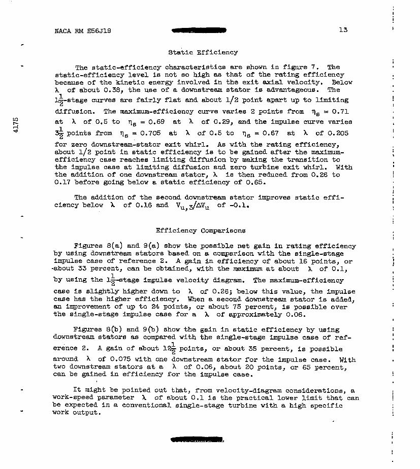
The efficiency characteristics of a single-stage full-admission turbine with downstream stators have been analyzed as a function of turbine work and speed requirementa. The range of the work-speed parameter X used (from 0 to 0.5) is that in which single-stage turbines with downstream stators ("&stage turbines") offer an effi- ciency advantage over conventional turbines for critical applications in turbojet engines, turbopumps, and accessory drives. Impulse and maximum-efficiency velocity diagram6 have been considered. The effi- ciencies of these two types were compared with that of the single- stage impulse velocity diagram, which yielded higher rating and static efficiencies in the range of X coneidered in this analysis. The loading on the downstream stators was limited by restricting the diffusion factor to 0.5. The following results were obtafned:
2
L
1. The 1-stage turbine with one downstream stator has a distinct 1 2
advantage Fn rating and static eff iciencies below X of 0.38. The effL ciencies do not vary to any extent until the limiting diffusion factor is reached, after which they decrease rather sharply. Limiting diffueion at zero turbine exit whirl for the maximum-efficiency velocity diagram is - reached fir& at X of 0.29 and for the impulse caee at about X of 0.205. For the range 0Y-X between the limiting diffusion of both cases, up to about l/Z-point increase in efficiency is obtainable by making a transi- tion between the two velocity-diagram types at zero downstream-stator exit whirl Etnd limiting diffusion. When a second downstream etator is added, an additional increase in rating and static efficiencies over that of one downstream stator can be obtained below X of 0.16.
c
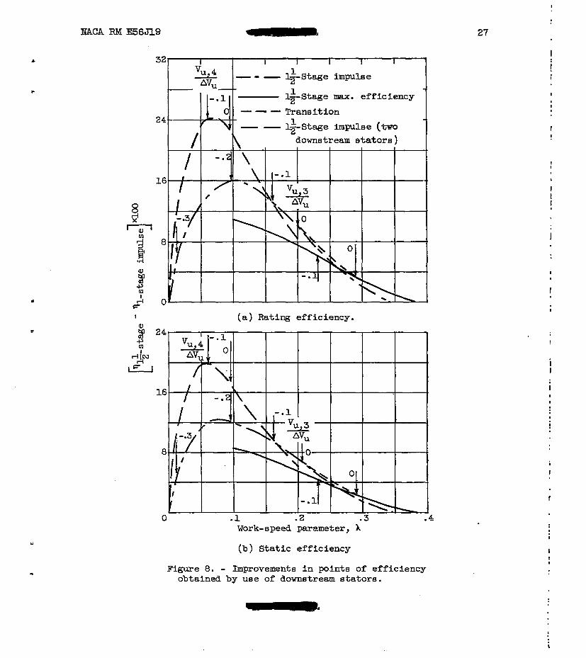
2. Rating-efficiency improvements in the impulse case of about 16 points, or 33 percent, are possible with the addition of one downstream stator, the maxim occurring around X of 0.1. With t w o downstream stators, improvements in efficiency up to about 24 pointe, or 75 percent, are possible, the maximum occurring at h of 0.06.
3. Static-efficiency improvements in the impulse case of about 1% 1
points, o r 35 percent, at X of 0.075 are possible with the addit-ion of one downstream stator. With two downstream stators, static efficiency is improved about 20 points, or 65 percent, at X of 0.06 over the single- stage impulse case.
Lewis Flight--Propulsion Laboratory National Advisory Committee for Aeronautics
Cleveland, Ohio, October 23, 1956
I
!
15
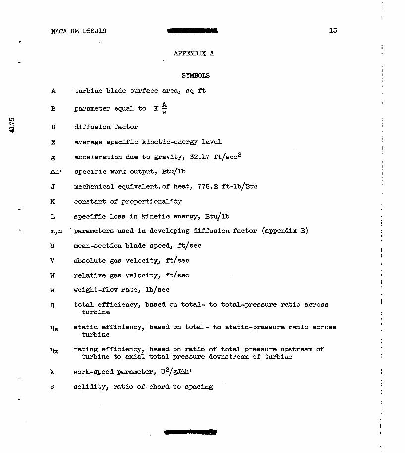
SYMBOIS
A turbine blade surface area, sq ft
B parameter equal t o K ;; A
D diffusion factor
E average specific kinetic-energy level
g acceleration due t o gravity, 32.17 f t /sec2
A h t spec i f ic work output, gtu/lb
J mechanical equivalent, of heat , 778.2 ft-Ib/gtu
K constant of proportionali ty c
L specif ic loss in kine t ic energy, Btu/lb
- m,n parameters used i n developing diffusion factor (appendix B)
U mean-section blade speed, f t / sec
v &solute gas velocity;, ft/eec
w r e l a t ive gas velocity, ft/sec
W weight-flow rate, lb/sec
‘1 to ta l e f f ic iency , baaed on total- t o total-pressure r a t i o across turbine
rlS s ta t ic e f f ic iency , baeed on t o t a l - to e ta t lc-pressure r a t i o across turbine
q, rating efficiency, based on r a t i o of total pressure upstream of turbine t o axial t o t a l pressure downstream of turbine
x work-speed pasmeter, U2/gJAhl L
0 so l id i ty , ra t lo o f . chord t o spacing
I
I
!
. - i
16
Subscripts :
MACA RM E56J19
av
id
R
S
8
U
X
0
1
2
3
4
average
idea l
ro tor
s t a t o r
static
tangent ia l
exfal
upstream of turbine
s t a t ion between upstream s t a t o r and rotor, upstream stator
s t a t ion between ro to r and first downstream s t a t o r , f i r e t downstream
. .
s t a t o r
s t a t ion downstream of first downstream s t a t o r
s t a t ion downstream of second downstream s t a t o r when used
I -
. . .
I
t
’ , I
NACA RM E56J19
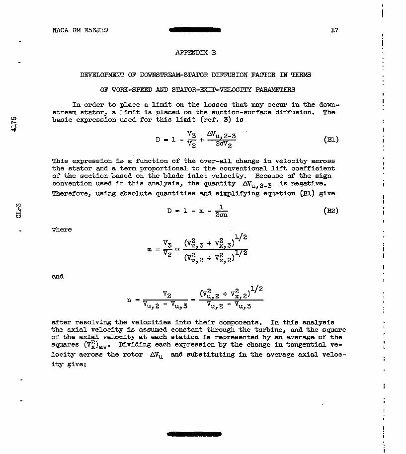
APPENDIX B
DEVELOPMENT OF D0WNSTREA"STATOR DlFFUSION FACTOR IN
OF WORK-SPEFD AND STATOR-EXIT-VELOCITY PAR"ERs
In order to p lace a l imi t on the losses tha t may occur i n t h e stream stator , a limit is placed on the suct ion-surface diffuion. basic expression used for this l imit (ref. 3) is
'3 + Avu,2-3 . D = 1 - - v2 20v,
17
Thfs expression is a function of the over-al l change in veloci ty across t h e s t a t o r and a term proportional to the conventional lift coeff ic ient of the sect ion based on the blade in le t ve loc i ty . Because of t h e sign convention used i n t h i s analysis., the quantity AVu,2-3 is negative. Therefore, using &solute quant i t ies and simplifying equation (BI) give
J V
- where
and
1 - m - - 2 m L
&er resolving the ve loc i t i e s i n to their components. In this analysis t he axial velocity is assumed constant through the turbine, and the square of t he axial velocity a t each s ta t ion is represented by an average of t h e squares (vZ),,. Dividing each expression by t h e change i n tangent ia l ve- loc i ty across the ro tor AVu and subs t i tu t ing in the average axid veloc- i t y give:
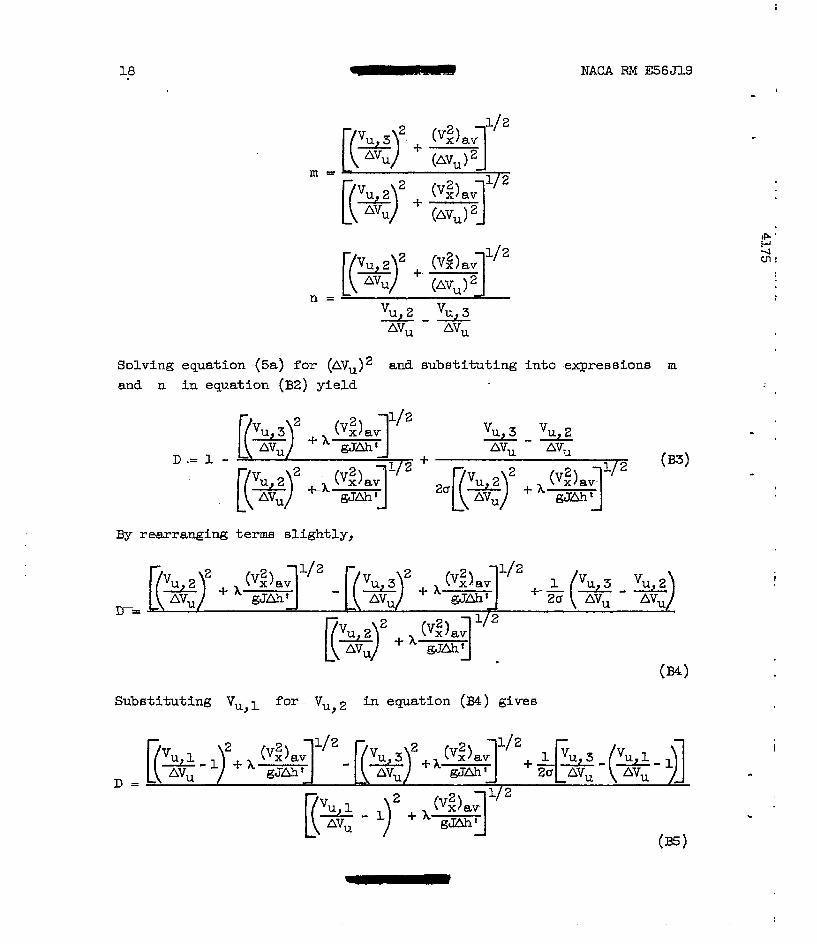
18 NACA RM E56Jl9
m =
vu,2 - vu,3 AV, AVu
Solving equation (sa) for (AVu)2 and substituting into expressions m and n in equation (B2) yield
By rearranging terms slightly,
+ vu, 3 AVU
Substituting Vu, 1 for- v u, 2 i n equation ( ~ 4 ) gives
c
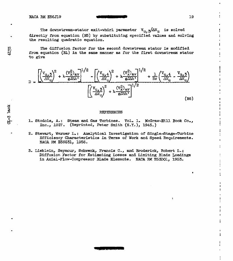
NACA RM E56J19 I 19
The downstream-stator exit-whirl parameter Vu,31hv, is solved . d i rec t ly from equation (E) by substi tuting specified values and solving
the resulting quadratic equation.
z G The diffusion factor for the second downstream stator is modified fYom equation (Bl) i n t h e same manner as for the first downstream stator to give
D =
7 d' 1. Stodola, A. : Steam and Gas Turbinee. Vol. 1. McGraw-Hill Book Co.,
Inc., 1927. (Reprinted, Peter Smith (N.Y.), 1945.)
2. Stew&, Warner L. : Analytical Investigation of Single-Stage-!l!urbine Efficiency Characterist ics i n Terms of Work and Speed Requirements. NACA RM E56G31, 1956.
3. Lieblein, Seymour, Schwenk, Francis C., and Broderick, Robert L. : Diffusion Factor f o r Estimating Losses and Limiting Blade Loadings i n Axial-Flow-Compressor Blade Elements. NACA RM E5-1, 1953.
!
!
I
I t
I
I
.. . ..
I
!
I
. . . - . . . . . . . . . . . . . . . . . . . . . . . . . . . . . . . . . . . . . . . . . . . . . . . . . . . . . -
Station a-
2
4
N 0
21
3
0 k
k ?3
Figure 2. - Turbine rotor exit-whirl characteristics for specified velocity-dfagram conditions.
I
i
!
I
I
i
I
I
NACA RM F56Jl9 22
- - - Impulse (one downstream statar ) , Impulse (two downstream stators) -
.5
Figure 3. - Downstream-stator diffusion characteristics 88 function of work-epeed parameter for solidity of 1.5.
I
I
23
L
U .I .6
Work- s peed parameter, x
Figure 4. - %-Stage turbine ro tor exit-whirl characteristics 1
for specified velocity-diagram conditions and di f fus ion factor of 0.5.
!
!
I
24
1
Figure 5. - Comparison of t o t a l efficiency of single- and
+stage turbines with limiting diffusion factor of 0.5. B, 0.030; (.",)av/gJAhv, 0.49.
1
i
t
I
I
I
NACA RM E56Jl9
Figure 6. - Comparison of rating efficiency of 8 ingle- and
%stage turbines with limiting diffusion factor of 0.5.
B, 0.030; (<)sv/gJaht, 0.49.
1
25 I
I
I
i
I
I
I
I
. I
I
2 6 mAcA RM E56319
Work-speed parameter, A
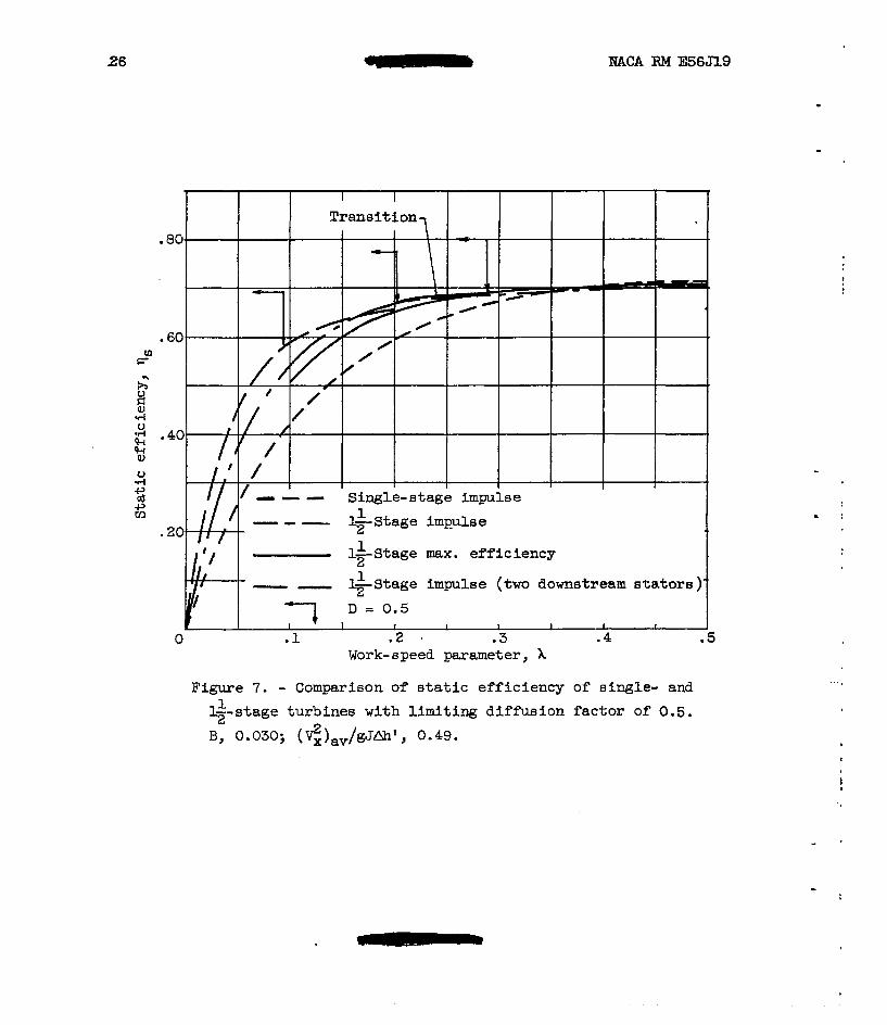
Figure 7. - Comparison of s ta t ic e f f ic iency of single- and
12” --stage turbines with limiting diffusion factor of 0.5.
B, 0.030; ($),v/gJAh‘, 0.49.
!
I
IW2.k RM E56319 - 27
. t
+-Stage max . ef f i c iency 1
(a) Rating efficiency.
Work-speed parameter, A
(b) Static efficiency
Figure 8. - Improvements i n points of efficiency obtained by use of downetream stators.
I
!
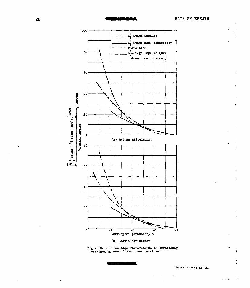
28 II NACA RM E56J19
$-Stage mx. efficiency Tramifion
1
""
eo - -+stage 1 impulse (tM
I
Uork-speed paraineter, A
(b) Static efiiciency.
Figure 9. - Percentage improvements in efficiency obtained by w e of downatrerm sfatOr6.
i
"
I
I