Embed Size (px)
Citation preview
RESEARCH MEMORANDUM
INVESTIGATION AT SUPERSONIC SPEEDS O F A TRANSLATING-
SPIKE INLET EMPLOYlNG A STEEP-LIP COWL L
B y Gerald C. Gorton
NATIONAL ADVISORY COMMITTEE FOR AERONAUTICS
WASHINGTON
(0 N
I
u NUX RM E54G29
Y NATIONAL AWISCBY COMMWEX FOR AERONAUTICS
RESEARCH
By Gerald C. Gorton
A n experimental Fnvestigation was conducted in the Lewis 8- by 6- foot supersonic wind tunnel at stream Mach numbers of 1.5, 1.8, and 2.0 on a translating-spike W e t analytically designed t o keep the cone shoulder downstream of the cowl-lip station ufthout a net internal contract ion. 3-
6 The present inlet, which incorporates an internal cowl-lip angle of 9 17.5O, w a s constructed t o have the stme inlet capture area and maximum
cross-sectional area as that of a previously investigated translating- spike in le t which hac3 an internal cowl-lip angle of only 7O.
The pressure recovery at cri t ical operation was Increased signifi- cantly over the inlet with 8 low cowl-lip angle, except for the extreme forward spike positions at stream Mach numbers of I. 8 and 2.0. This gain in pressure recovery was at the expense of a higher cowl pressure drag and a decreased stable mass-flow range.
At crit ical operation the Fncreased pressure recovery more than compensated for the higher cowl pressure drag, and resulted in a sig- nif icant gain a effective thrust .
Analysis and experimental evaluation of translating-spike W e t s indicate that such inlets can sat iefy the jet-englne ai& flow require- ments while operating near the optimum inlet condition. The design of translating-spike inlets is complicated, however, by the fact that an inlet designed with a low cowl-iip angle generally experiences internal
2, excessive internal contraction results in lower pressure recovery and higher drag at c r i t i c a l flow. With the spike extended a loss in
. contraction when the h i k e is retracted. As shown in references 1 and
1 flow the cone shoulder ."
2 I._ NACA RM E54G29
Ln a discussiun of the design problems as.sochted with translating- Y
spike inlets, it was stated (ref. 1) that an inlet could be designed t o keep the cone shoulder downstream of the cowl lip for the entire range of spike translation wlthout internal contraction. An analytical expres- sion has been derived describing such i i i inlet (see apgndix) and an 8- inch-diameter model-based on this design criterion w&s constructed and evaluated in the XACA Lewis 8- -by 6-foot Kupersohic wind tunnel. The results of this Investigation are presented herein.
SYMBOLS
The following symbols are used throughout the report :
A flow @ea, sq f t
maximum external cross-sectional area; 0.360 sq f t
cD ex te rn -&= coefficient; ~lson, CF,= coefficient of thrust minus drag
D drag force, Ib
F thrust with actual total-pressure recovery, lb
Fi thrust with 100 percent total-pressure recovery, lb
*
. . . L
c
M Mach nuuiber
m mass flow, slugs/sec .. . - , "
m ma66 flow through stream tube defined by cowl-lip area, slugrs/eec 0 P total pressure, Ib/sq f t
p-.. s tatic pressure, Ib/sq ft ." . . - - . . " . "" .. "" - "_ . . .
9 dynamic pressure, &/2, lb/sq f t
wJe' corrected air-flow peameter, lb/(sec} (sq ft ) 6A
W air flow, lb/sec . . .. . .
X axial distance downstream of cowl lip, in.
NACA RM E54G29 3
a angle of attack, deg L
Y ratio of specific heats for air, 1.4 for calculations reported here in
6 total pressure divided by NclCA standa,rd sea-level static pressure
e stream t o t a l temperatures divided by NACA s t a n d a r d sea-level s t a t i c temperature
$ 2 cowl~position parameter (angle between axis of diffuser and l i ne joining apex of cone t o cowl l ip) , deg
Subscripts :
0 free stream
3 plane of survey
%- (d A€?PLxRmUs m P R m m P
The 8-Fnch diameter tranalatlng-spike-inlet m o d e l w a s sting-mounted in the 8- by 6-foot supersonic wind tunnel and investigated at Mach num- bers of 1.5, 1.8, and 2.0. The Reynolds nuuiber was approximately 3 .e10 based on the maximum external diameter of the model (8.125 in. } . 6
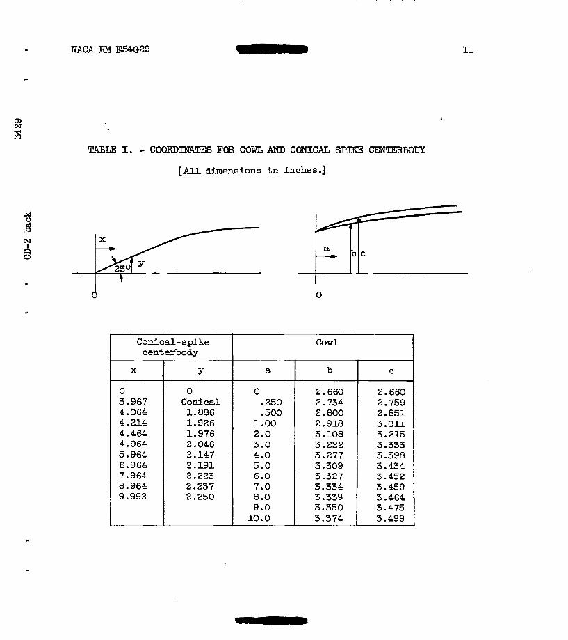
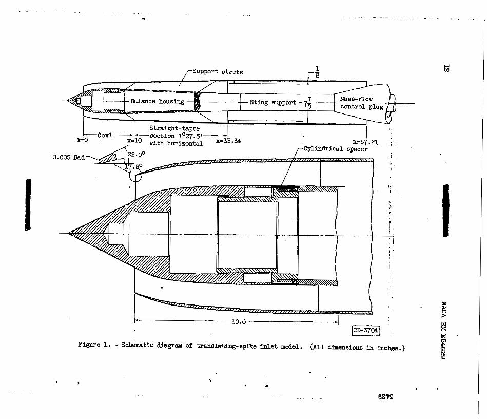
!?%e basic model (see f i g . 1) w a s ident ica l to the model of refer- ence 1 with the exception of the inlet cowl and the conical-spike center- body. The inlet cowl and the conical-spike centerbody ( ~ e e table I f o r coordinates) were designed t o have the cone shoulder at the cowl-lip s ta t ion for the most forward epi3se position (82 = 34') and t o allow re- traction of the splke t o 8z = 54 without a net Fnternal contraction (see f ig . 2 for diffuser-flow-area variation). The analytical design procedure is shown in the appendlx.
E)
In order t o achieve such a design, it w&s necessary, as shorn in the appendlx, t o u t i l i z e an internal cowl-lip angle of 17.5O compared w i t h the 7' internal cowl-lip angle of the m o d e l of reference 1. How- ever, to f a c i l i t a t e comparison between the two models, the same in le t diameter of 5.32 inches was maintained. It was necessary, however, t o increase length of the present model by 1.34 inches. In addition, cylindrical spacers were used t o simulate spike translation rather than faired spaceFCas were used i n the model of reference 1. Cylfndrical spacers more nearly represent the translating mechaism that would be used i n a practical inlet.
4 NACA RM E54G29 6
The instrumentakion consisted of a static-pressure rake a t s t a t ion 3, a three-component strain-gage balance within the m o d e l centerbody, a movable plug at the exit of the model with which t o vary the -6 flow, a direct-reading angle-of-attack indicator, and a aynamic pressure pickup located slightly downstream from the plane of survey. The dynamic pres- sure pickup was used i n conjunction with schlieren apparatus t o evaluate inlet-flow instability. The. onset of instabi l i ty w&8 abrupt enough t o allow reasonable acZmcy in aetemining the mass-flow ra t io at which pulsing started."" - - -
.I
- - . . . . . ." ." - . . . " ". "".."_ ~.., I._ .. . . " - - .".
a,
The mass-flow ratio presented is the ra t io of mass flow through the 3 model % to that mass flow o f a free-stream tube defined by the capture area of the inlet cowl. The mass flow was calculsted.by assuming a choked condition at the exit-nozzle throat and using the measured aver- age static pressure and the calculated diffuser Mach nunber at the plane of survey. The Mach number at the plane of survey was determined from the area ratio &sting between the plane of survey and the choked exit assuming isentropic one-dimensional flow. This Mach n&er was converted
t o a corrected air-flow parameter
engine-inlet matching.
w3& "sA.3 f o r convenient application to
Total-pressure recovery is the r a t io of the t o t a l pressure Pg, de- termined f r a r t h e measured average stat ic pressure and the calculated Mach number at the plane of survey, t o the masurea free-stream total pressure Po.
External-.&ag and thrust-minus-drag coefficients were computed from axial-force readings of the strain-gage balance In conjunctim with internal-pressure aeasurements . The forces on the mass-flow plug were not registered by the strain-gage balance.
The effective thrust parameter - was calculated accordin@; to F - D Fi
the method set forth in reference 3, using the measured inlet pressure recovery and the drag data in conjunction with lmown engine specifica- tions and air-flow requirements.
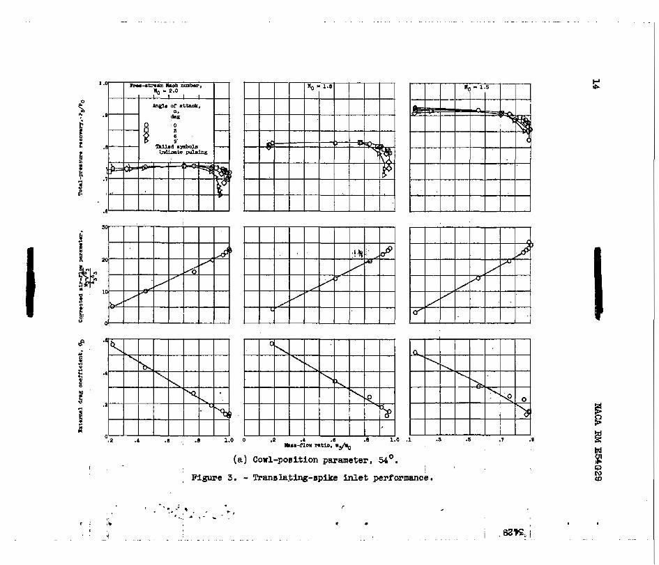
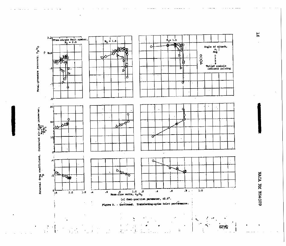
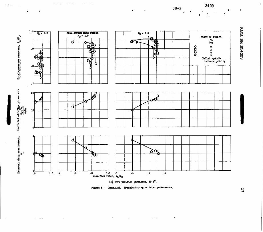
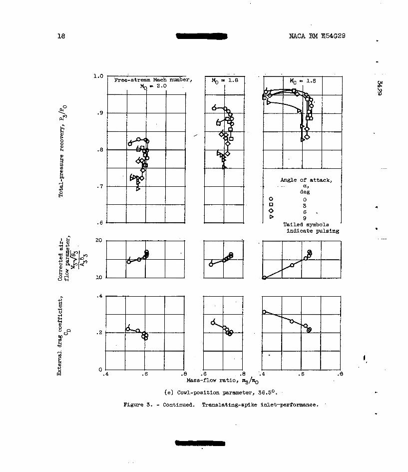
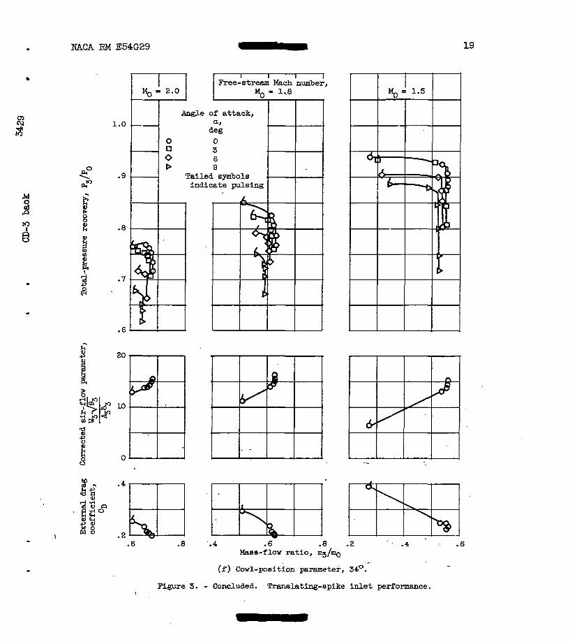
Total-pressure recovery PdF0 for the ran@;e of cowl-position parsm- *
eter investigated is presented in figures 3(a) t o ( f ) f o r stream Mach numbers of 1.5, 1.8, and 2.0 fo r angles of attack of Oo, 3O, 6O, and 9'. he e x t e r n &ag coefficients ana correcteg air-flow parameter for zero angle of attack are also included. These performance characteristics are presented as a function of mass-flow ra t io -g%. -.
c
WCA RM E54G29 b
5
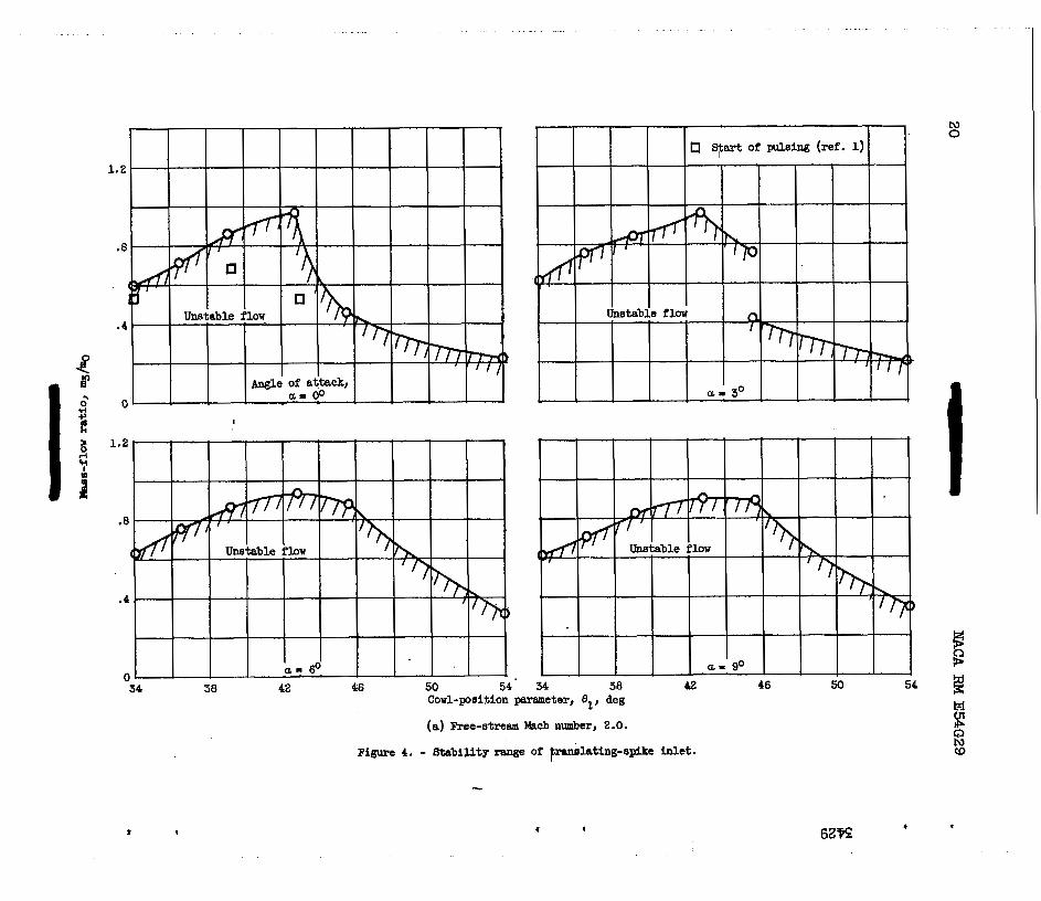
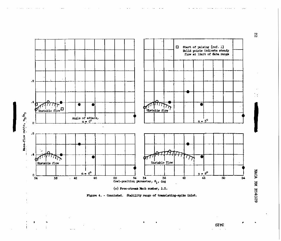
Figure 4 shows the variation in stable mass-flow range as a function - of spike translations for various angles of attack. The inlet of the present investigation has less stable mass-flow range than the translating- spike inlet reported in reference 1. It should be noted that aside f r o m the difference in internal cowl-lip angles there was considerable dif- ference i n the dfffuser-area variations of the two models. The model of reference 1 had an essentislly constant area section for the initial por- t ion of the diffuser, while the present model initia,lly diffused quite
w rapidly at most of the spike positions. A constant-area section has been R shown t o be an effective way t o increase the stable mass-flow range of an (0 amdar i n l e t (see ref. 4).
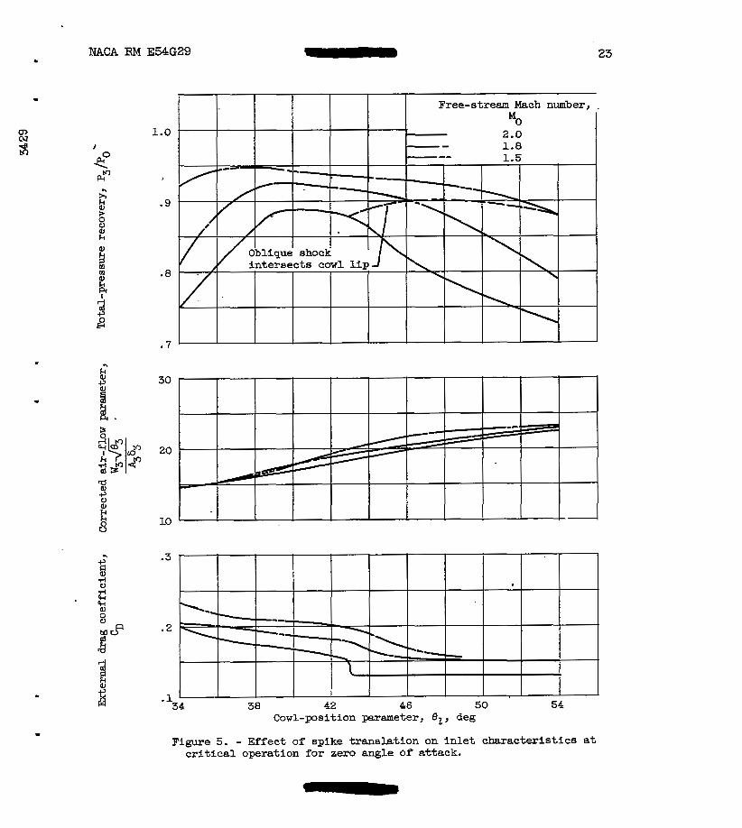
The effect of spike translation on the inlet perf ormaace at c r i t i c a l operation is presented in figure 5 for zero angle of attack. Pressure recovery is generally raised as the spike is translated to values of cowl-position parameter et less than 54. This increase is m ~ l f n l y the result of increasing the amount of flow passing an oblique shock pr ior t o the normal shock. However, the pressure recovery does start t o de- crease quite abruptly at the extreme forward. spike positions. This may indicate that the rate of diffusion is too rapid, causing separation losses. Concurrently the n o m 1 shock is in the vicini ty of the cone shoulder and possibly may result in reexpamion losses.
,
The external drag coefficients presented Fn figure 5 indicate the variation of c r i t i c a l flow drag with spike translation. It should be noted that.- at Q = 2 .O the fair ing of the drag curve between 82 = 45.6' and 42.8O is arbitrary, since the exact 82 at which the drag increased was not established. A few typical schlieren photographs are shown In figure 6 for various d u e s of spike position. Note that at Mo = 1.5, the cowl-lip angle was steep enough t o cause a detached shock t o form at the cowl l i p .
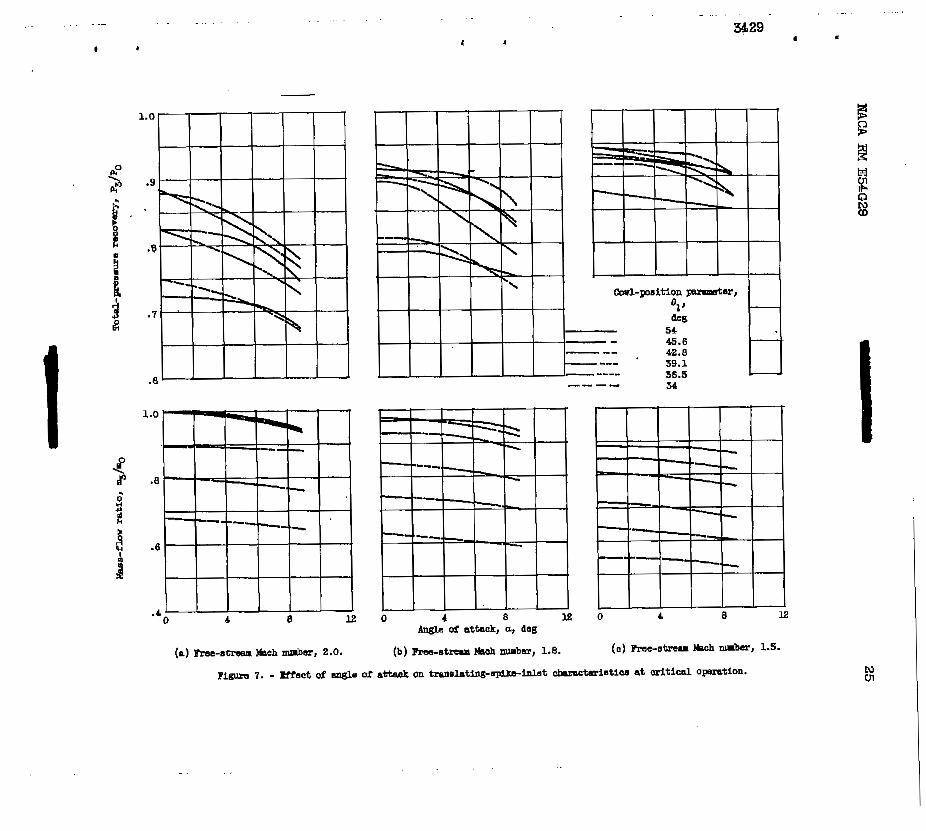
Angle-of-attack performance at cri t ical operation is shown in figure 7. Pressure recovery appears t o be generally more sensitive t o angle of attack when the spike i 6 i n the forwa3.d posit ions.
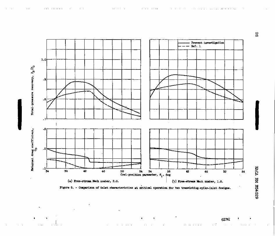
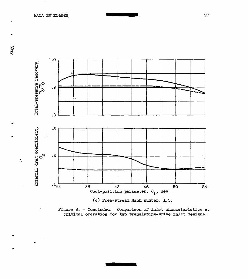
The conqarisons of the present translating-spike inlet and the translating-spike inlet of reference 1 are shown in figures 8 t o 10. Figure 8 compares the zero-angle-of-attack critical-flow pressure recov- ery and drag performance as a function of spike translatfon. A t a stream Mach nmiber of 2.0 with the oblique shock at the cowl l ip , there waa a gain in recovery of 3 percent of free-stream total pressure over the inlet of reference 1. With the spike positioned for approximately 10 percent oblique shock spiJlage ( e z = 39) the gain was about 5 percent and was a maximum value. As the spike was t rans la ted to values of 82 39O, the pressure recovery coamnenced t o decrease quite rapidly until at
1
' 6 - NACA RM E M 2 9
82 = 35.8 the present inlet started t o give poorer pressure-recovery performance than the inlet of reference 1. The same trends occur a t % = 1.8. A t plo = 1.5 the present M e t exhibited sugerior pressure- recovery performance for the ent i re range of translation.
The externaI.-drag-coefficient h t a of figures 8 ( a > t o ( c > m u s t r a t e the penalty paid, in cowl pressure drag, f o r .the increased pressure re- covery. The change i n external drag coefficj-ent (0 -10 t o 0 -13) a t
= 43' fo r % = 2.0 indicates the increase in cowl pressure &rag re- sult ing from the steep cowl-lip w e , inasmuch as a full stream tube is being captured and the change in friction drag is negligible. Homer, -3 when the sp-e was retracted t o 82 > 50' at % = 1.5 the external drag coefficient was lower than that of .the translating-spilre inlet of refer- ence 1. This results framthe fact that the present inlet spi l l s l ess mass f l o w than the M e t of reference 1. The spillage with the present inlet resul ts from the detached shock at the cowl l i p , whereas the inlet of reference 1 experienced spillage because of excessive internal contract ion. - " . -
Oa
Since the over-all evaluation depends on the combination of drag and pressure recovery, thrust-minus-drag coefficient8 calculated fro& model-balance measurements are presented for cr2bical operation in f ig- ure 9. The present -.inlet shows increased thrust-minus-drag performance over the .translating-spike inlet of reference 1 except f o r the extreme forward spike positions at % = 1.8 and 2.0 *re the pressure-recovery performance decreased quite rapidly.
(I
I _
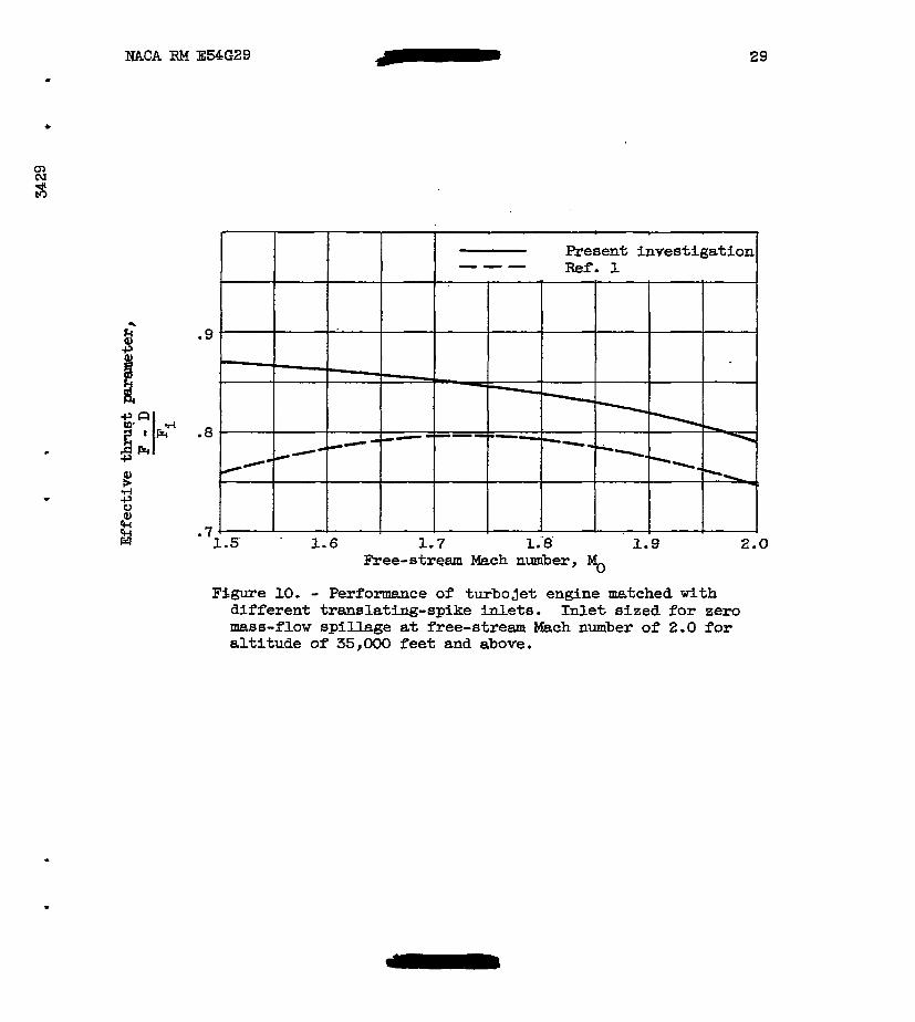
A more practical evaluation of the superiority of the present translating-spike inlet over the one of reference 1 I s shown in figure 10 where a typical turbojet engine is maf%hed to both inlets over the Mach number range fram 1.5 t o 2.0. Both inlets were sized for zero spillage at % = 2.0. A t the lower Mach nuuibers, matching at c r i t i ca l operation was accomplished by translating the spike.
i
The effective thrust parameter - ' -is increased 6 percent a t F i
MO = 2.0, 6 percent at % =I 1.8, and 14 percent a t MO = 1.5 by using the translating-spike inlet of the present investigation. The increased gain at % = 1.5 results from the elimination of intemial contraction. The excessive interaal contraction present with the inlet of reference 1 caused more spU+ge than the amount required far matching a t c r i t i c a l operation, thua requfring the in le t t o operate sugercritically. The pre- sent translating-spike inlet allowed match- at cri t ical operation.
The capar i son presented based on an inlet sized far zero spillage v
at Mo = 2.0 does not &ow the present inlet t o take advantage of the increase in pressure recovery available by sizing for some oblique shock I
spil lage at = 2.0. On this basis, the present inlet is capable of showLng even greater advantage over the inlet of reference 1.
b mCA RM E54G29
i.
cI1 rp N co
7
The following results were -obtained f’ram 8.n analytical and experi- mental investigation at Mach nrmibers 1.5, 1.8, and 2.0 of a trbaslating- spike U t :
1. A translating-spike M e t can be designed, from an analytical expression, which w i l l keep the cone shoulder downstream of the cowl l i p without the necessity of internal contraction.
2. The pressure recovery at critical operation increased signifi- cantly over an inlet b v i n g a l o w cowl-lip angle except for the extreme forward positions of the spike at Mo = 1.8 and 2.0. This gain in pres- sure recovery was at the expense of higher cowl pressure drags and &
decreased stable lnass-flow range.
3. The increased pressure recovery more than carpensated for the higher cowl pressure drag, and resulted in a significant gain in effec- t i ve thrust.
Lewis Flight Prqpulsion. Ile;boratory National Advisory Committee for Aeronautics
Cleveland, Ohio, August 3, 1954
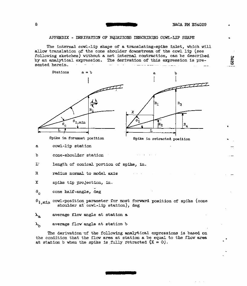
The internal cowl-lip shape of 8 translating-spike inlet, which will allow translation of the cone shoulder downstream of the cowl l i p (see following sketches) without a net internal contraction, c8n be described by an analytical expression. The derivation of this expression is pre- E sented herein. . . .. . . - . . .. .. - . .. . " 3
Stations a = b a b
I I I
I
Spike in foremost position Spike in retracted posit ion
a cowl-lip sta t ion
b cone-shoulder s ta t ion
c length of conical portion of spfke, in. R radius normal t o model axis
X spike t ip pro jectbn, in. *C
- cone half-angle, deg
%,mill cowl-posItian parameter for most forward position of spike (cone shoulder at cowl-lip station}, deg
x, xb
average flow angle at s ta t ion a
average f l o w angle a t s ta t ion b
The derivation of the following analytical expressions is based on the condition that the flow area a t s ta t ion a be equal to the flow area at station b when the SpFke is . f u l l y retracted (X = 0).
t
"
. .
. -
.-
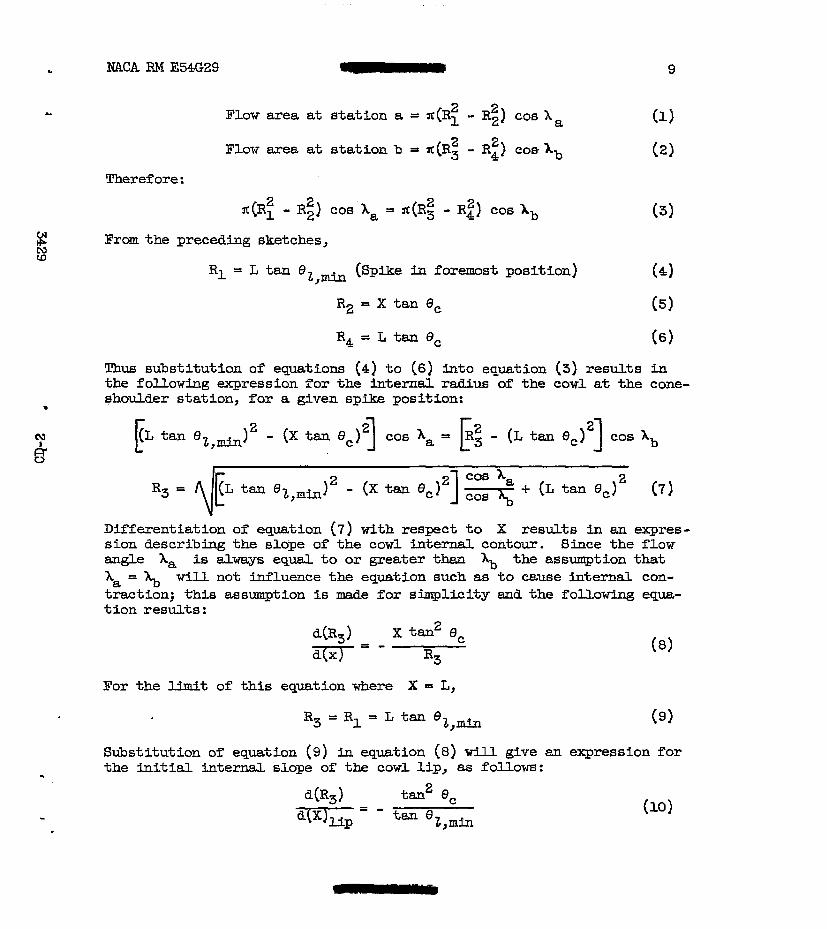
L NACA I34 E54G29 - 9
I Flow area at stat ion a = x(Rl 2 2 - R2) cos X a
Flow area at stat ion b = YC (R: - R4 1 coe Ab 2
Theref ore :
.(RH - R2) 2 cos Xa = .(R$ - Rt) cos Ab (3)
N co Prom the preceding sketches,
R1 = L tan (Spike ~n foremost position) (4)
R 2 = X tm 8, (5)
R4 = L tan 8, (6)
Thus substitution of equations (4) t o (6) i n to equation (3) results in the following expression for the internal radius of the cowl a t the cone- shoulder station, for a given spike position:
m
Differentiation of equation (7) with respect t o X results in an expres- sion describing the slope of the cowl internal contour. Since the flow angle X, is always equal to or greater than the assumption that Xa = will not influence the equation such as t o cause internal con- traction; this assumption is made for sinrplicity and the following qua- t ion results :
d(Rg) X tan 8, 2
ma- R3 For the limit of t h i s equation where X = L,
Sdxt i tu t ion of equation (9) in equation (8) will give an expression for the InitiaL internal slope of the cowl l ip , as follows :

From equation (10) it is apparent that the internal cowl-lip angle * necessary f o r such an inlet as described here3.n i a a function of the cone half-angle 8, and the most forward pos.ition of the spike, which places the cone shoulder at the cowl-lip station. Figure ll pre- sents the required Initial internal cowl-lip angle f o r cone half-angles of ZOO, 2 5 O , and. 30' fo r a range of mFnimum cowl-position parameter.
. "
The analytical expression is likewise valid fo r a d t i s h o c k M e t where GC and 8 are determined from the . . last conical portion of m
the spike. 3 The procedure t o be followed in a typical de6i.p is as follows:
(1) A f f i x the inlet capture area e;nd the cone half-angle 8,.
(2) For the. desired forward translation 82,min determine the length of the conical portion of the splke, L.
(3) F r m equation (lo), knowing 8, and 6 ~ , ~ h , t h e i n i t i a l inter-
(4) Fram equation (7) (assuming 1, = h}, the coordinates of the
nal cowl-lip angle can be determined. .. - . "
cowl can be determined fo r the desired amount of spike retraction.
* (5) The coordinate of the cowl and centerbody downstream of the cone-shoulder s ta t fon can now be determined according t o the desired maximum model cross-section area and diffuser flow-area variation. It should be noted that the cone shoulder ned not be the maximum diameter of centerbdy .
1. Gorton, Gerald C; : Inirestigation of Translating-Spike Supersonic In le t a8 Means of Mass-Flow Control at Mach HWers of 1.5, 1.8, and 2 .O . NACA RM E53G10, 1953.
2. Leiseler, L. Ahbott, and. Sterbentz, W i l l i a m E. : Investigation of a Translating-Cane klet at Mach Nunibem fran 1.5 t o 2.0. NACA RM E54B23, 19%.
3. memzier, E5nll J.: A Metlaad for Evaluating the Effects of Drag and Inlet Pressure Recovery on PropuLsion-6ystem Performance. NPLCA TN 3261, 1954.
4 . Nettles, J. C.: The Effect of Initial Rate of Subsonic DLffusion on the Stable Subcrit ical Mass-Flow Range of a Canlcal Shock D i f f u s e r . NACA RM E53E26, 1953.
NACA RM E54G29 11
TABL;E I. - C O I N A T E S FOR COWL AND C a I C A L S P m CENTERBODY
[All dimensions Ltn inches.]
. d
.I
t I 0
Conical-spike centerbody
X
0 3.967 4.064 4.214 4.464 4.964 5.964 6.964 7.964 8.964 9.992
Y
0 conics1 1.886 1.926 1.976 2.046 2.147 2.191 2.223 2.237 2.250
t a
0 .250 .500 1.00 2.0 3.0 4.0 5.0 6.0 7.0 8.0 9.0 10.0
c o w l
b
2.6a 2.734 2.800 2.918 3.108 3.222 3.277 3.309 3.327 3.334 3.339 3.350 3.374
C
2.6m 2.759 2.851 3 . O n 3.215 3.333 3.398 3.434 3.452 3.459 3.464 3.475 3.499
1
/-Support struts 1
. . . . . . . . . . . . . .

. . . . ..
I I I
I
. . . . . . . .
I
1.0
.6
.4
.2
0 .1 .2 ' .3 .4 ' .s .6 .7 .8 .9 1.0 I
! Me&ce Rom b w l Up/iength of model, x/57.21
Figure 2. - D i m e r flow-area variation.
. . " . . . . . . . . . . . . . . . . . . . . . . . . . .. . . . . . . . . . .. . . . . . . .. . . . - . .. .. . . . . . ."
E
a ) corl-poeLtIon parameter, 54'. , Figure 3 . - Transla$iqpspike N e t performance.
. . . . - / <
r j :+ '... A * - . * I
r . . . 9 .. . . . . . . . . . . . . . . . . . . . . . . . . . . . . . . . . . . . . . . . . . . . . . . . . . . . . . . .

. . 3 4 w ' "
1.0
.B
.8
.7
f5
15
6
.e .E 1.0 1.e .2 .b * a .B 1.0 llano-f1.m m t i o , .3/mo
(b) ~ l - p o s i t i m parpmeter, 45.6'.
.P A .6 .8 1.0
i g a * E H D b
:.a 1.0 1.a
I
1 L I
.e
0 .8 1.0 .4 .E .El 1.0
b." ratio,
I
NACA RM E54G29
1.0 1 Free-stream W c h number,
.9
.7
.6
. 4
.2
0 .4 .6 .a .6 .a
Angle of attack,
deg =, 0 3
0 0 0 6 - D 9
Tailed symbols ..
indi cwke pulsing
I
-. 4 . 6 Mass-flow ratio, m&o
(e) Cowl-position parameter, 36.5O. -
Figure 3. - Continued. Translating-epike lnlekperfonnance. '
NACA FM E54G29 - 19
z B 6 M I
Angle of attack,
0 0 0 D
.9
0 3 6 9
Tailed symbols indicate pulsing
20
Lo
0
.6 .8 .4 .6 .8 .2 .4 ' .6 bss-flov ratio, m3/mg
[f) COWl-poSitiOQ pW&kr, 3 P .
F'igure 3. - Concluded. Tmnslating-spike in le t performance. I
. ..
N 0
c
54 38 42 46 50 54 34 38 42 46 54
I 6 2 s b

1.2
.8
.a
0
" 34 58 42 46 50 54 34 38 42 46 50 54
Cowl-psition parameter, 01, deg
(b) Fres-atream *ab number, 1.8.
nigurc 4. - Continued. Stabi l i ty range of tranelating-spike inlet.
. . . . . , . . . . .
.B
.4
0 46 34
' I b
I
1
N N
c
MACA RM E54G29 - 23
1.0
.9
.8
.7
30
20
.3
.2
.1 34 38 42 46 50 54
Cowl-position parameter, B2, deg
Figure 5. - Effect of spike translation on in le t characteristics at critical operation for zero angle Of attack.

. . . . . . . . . . . . . . . . . . . . . . . . . . . . . . . . . . . . . . ..
I 45.6 42.8 39.1 56.5
(a) Free-stream Mssh wmbsr, 2.0.
36. I
' b I
.. . . . ... .. . .
I
. . ."
I I
. .
4 1
p
\ B EP
3829 1
P
"" s4 I
N cn
. , . . . . . . . . . . . . . . . . . . . . . . . . . . . . . . . . . . . . - . . . . .. . .
P f
* I
I . . . . . . .
ax * . . . . . . . . . . . . . . . . . . . .
EACA RM E54G29,
.
1.0
.9
.8
.3
.2
27
' 5 4 38 42 46 50 54 Cowl-position Brameter, Bz, deg
(c) Free-stream Mach number, 1.5.
Figure 8. - Concluded. Comparison of inlet characteristics at critical operation for two translating-spike inlet designs.

1.2
1.0
.6
1.0
.8
.6
.4
.8
.6
- 4
. . . . . - .
"
34 38 42 46 50 54 Cowl-position parameter, deg
Figure 9. - Thrust-minus-drag comparison at critical operation for two translating-spike inlet designs.
. .. ..
t
1 " "
NACA RM E54G29 c
29
Free-stream Mach number, % Figure 10. - Performance of turbojet engine matched with different translating-spike inlets. Inlet sized f o r zero mass-flow spillage at free-stream Mach number of 2.0 for altitude of 35,000 feet and above.

30
20
10
0 . 32 34 36 38 40 42 4.4 46 48 50
Minlmum cowl-position parameter, % , a n ' Figure 11. - Required i n i t i a l intern1 cowl-lip angle for translating-splke inlet deslmed for no net internal contraction.
I