Embed Size (px)
Citation preview
Sensors & Transducers, Vol. 196, Issue 1, January 2016, pp. 82-87
82
Sensors & Transducers© 2016 by IFSA Publishing, S. L.
http://www.sensorsportal.com
Research of an Optoelectronic Current Transformer Based on a Designed Magneto-Optic Sensor
1, * R. El-Bashar, 1 J. El-Azab, 1 Y. Badr and 2 R. Yousif 1 National Institute of Laser Enhanced Sciences, Cairo University, Egypt
2 Electrical Power and Machines Department, Faculty of Engineering, Cairo University, Egypt * Tel.: +201064088409
* E-mail: [email protected]
Received: 2 January 2016 /Accepted: 25 January 2016 /Published: 30 January 2016 Abstract: An Optical Current Transformer (OCT) with dual polarimetric configuration is evaluated using a magneto-sensitive glass SF-59 of 0.4 and 1.3 cm lengths located into an air gapped conventional current transformer (CCT) iron core. Using a 5 mW He-Ne laser light source at 632.8 nm, the maximum current measured is nearly 2800 A with maximum error of 0.6 % and 1 % for the two sensors lengths 0.4 and 1.3 cm, respectively. The results have been experimentally limited by the maximum output of Variac. The simulation of the electronic circuit of the current transducer is introduced and the results indicated the reliability and accuracy of using the OCT in measurement and protection. Copyright © 2016 IFSA Publishing, S. L. Keywords: Verdet constant, Optical current transformer, Optical current sensor, Bulk glass. 1. Introduction
Due to the recent demand of power consumption and expansions of electric power system network, a great number of protection zones become available and requires intelligent system. Current sensors are important devices as they are not only give the accurate power consumption but also used for the fast detection and identification of failures points in power systems. However, CCT have enormous limitations due to their saturation problems, huge size and weight, high insulation cost as well the sensitivity to electromagnetic interference (EMI) [1].
Recently, optoelectronic technology is one of the evolved solutions of CCT problems by converting the CCT output voltage into a corresponding frequency modulated optical signal. This signal is not influenced by EMI and is congruous with intelligent network of current measurement and protection.
However, this technology could not overcome the iron core (IC) saturation [2]. The development of the measurement circuit of Rogowski coil sensor which does not involve IC, for high current measurement is still in progress [3]. On the other hand, magneto-optic sensing method provided an alternate solution for solving the CCT problems [4]. It consumes less power as compared to the traditional Dc Hall Effect sensor used in plants such as aluminum factories [5]. OCT can be integrated with fiber-optic based Ethernet local area networks. Besides, replacing the traditional solution which digitizes the CCT output for relays, meters, and SCADA systems [6].
The effect of the magnetic field on the transmission of light through certain transparent optical material was first observed by Michael Faraday in 1845 [7]. He noticed that, when the transmitted linearly polarized light is subjected to a magnetic field in the direction of propagation, the
http://www.sensorsportal.com/HTML/DIGEST/P_RP_0208.htm
Sensors & Transducers, Vol. 196, Issue 1, January 2016, pp. 82-87
83
plane of polarization rotates. Based on this effect, optical current sensors were developed into mainly two types; bulk glass sensors and fiber optical sensors. In bulk sensors, an optical material sensitive to the magnetic field is positioned parallel to the lines of magnetic field induced by a conductor carrying the current to be sensed. This sensor has the advantages of small size, low cost, weak influence of the environmental conditions such as temperature, pressure and other noises and high sensitivity to magnetic field. The sensitivity of the sensor is directly proportional to the length of the material subjected to the magnetic field. To increase its sensitivity, the sensor was designed to surround the conductor. The geometrical structure promotes the propagation of light parallel to the magnetic field lines. It can be either rectangular or triangular and sometimes circular [7-9]. In this case, the sensitivity is based on the sensor structure and/or the multiple path of light within the optical material [10].
An alternative technique is to utilize a small bulk sensor which does not surround the conductor while compensating the reduced sensor length by using a material with a high Verdet constant [11-13] and a concentrator core to increase the magnetic field [14-16].
In this work, an evaluation of a dual quadrature polarimetric sensitive optical current sensor inserted into a gapped IC is carried out. In Section 2, the design of the optical current sensor (OCS) in a gapped IC will be introduced. The proposed electronic circuit of the OCT will be presented in section 3. The simulation of the electronic circuit and optical sensor experimental results are introduced in Section 4 and will be concluded in Section 5.
2. OCS System Design
2.1. Optical Current Sensor
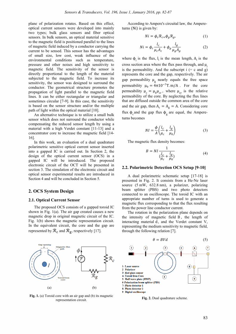
The proposed OCS consists of a gapped toroid IC shown in Fig. 1(a). The air gap created causes a new magnetic drop in original magnetic circuit of the IC. Fig. 1(b) shows the magnetic representation circuit. In the equivalent circuit, the core and the gap are represented by and , respectively [17].
(a)
(b)
Fig. 1. (a) Toroid core with an air gap and (b) its magnetic
representation circuit.
According to Ampere's circuital law, the Ampere-turns Ni is given by:
, (1)
(2)
where ϕi is the flux, li is the mean length, Ai is the
cross section area where the flux pass through, and μi is the permeability. And the subscript i (= c and g) represents the core and the gap, respectively. The air gap permeability μg nearly equals the free space
permeability μ 4π10 T.m/A . For the core permeability μc μ0μcr , where μcr is the relative permeability of the core. By neglecting the flux lines that are diffused outside the common area of the core and the air gap, then Ac Ag A. Considering core
flux ϕcand the gap flux ϕg are equal, the Ampere-
turns becomes
(3)
The magnetic flux density becomes:
1
(4)
2.2. Polarimetric Detection OCS Setup [9-10]
A dual polarimetric schematic setup [17-18] is presented in Fig. 2. It consists from a He-Ne laser source (5 mW, 632.8 nm), a polarizer, polarizing beam splitter (PBS) and two photo detectors connected to an oscilloscope. The toroid IC with an appropriate number of turns is used to generate a magnetic flux corresponding to that the flux resulting from the power line conductor current.
The rotation in the polarization plane depends on the intensity of magnetic field B , the length of interacting material d , and the Verdet constant V, representing the medium sensitivity to magnetic field, through the following relation [7].
(5)
Fig. 2. Dual quadrature scheme.
Sensors & Transducers, Vol. 196, Issue 1, January 2016, pp. 82-87
84
Through Mauls’s law, the output from the PBS (Po is given by
P0=P1cos2(), (6)
where is the angle between transmission axes of the polarizer and the PBS, P1 is the power transmitted from the polarizer. The sensor sensitivity is optimized by adjusting the polarizer transmission angle to 45 degree with respect to the PBS. In the absence of the magnetic field (i.e. no electric current applied), the angle between polarizer and PBS remains 45o. The angle of rotation for the two outputs is altered in the presence of magnetic field to be:
45 ,
where is the angle of Faraday rotation. Thus, the light power outputs from the PBS falling on the detectors become:
12
12
2 (7)
12
12
2 (8)
The two optical detectors convert the optical
signal into electrical signal where the subtraction and addition are executed electronically. By dividing the two components (subtraction and addition) by an
electronic divider, the resulting signal is proportional to the applied current. The division of these components also removes the effect of the light power fluctuation [9]. The output signal of the electronic divider becomes:
And for small angles,
2 2 (9) In case of alternating currents, the output signal
can be expressed by:
8 101
(10)
3. The Proposed Electronic Circuit of the OCT
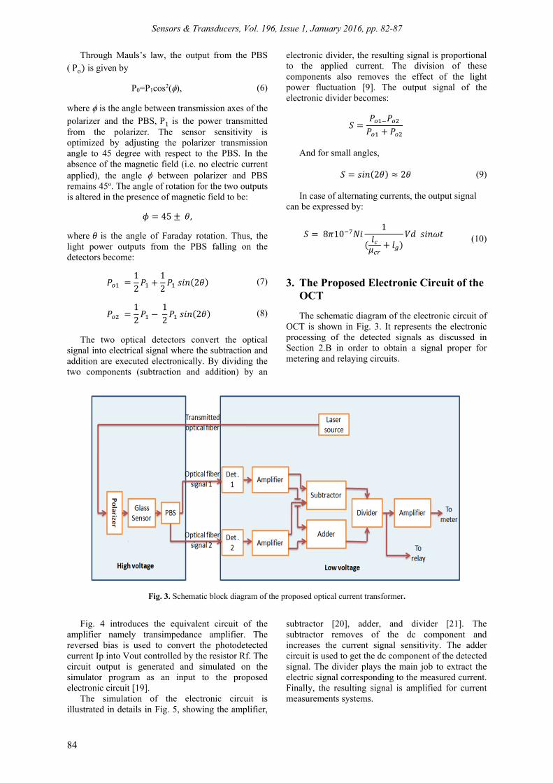
The schematic diagram of the electronic circuit of OCT is shown in Fig. 3. It represents the electronic processing of the detected signals as discussed in Section 2.B in order to obtain a signal proper for metering and relaying circuits.
Fig. 3. Schematic block diagram of the proposed optical current transformer.
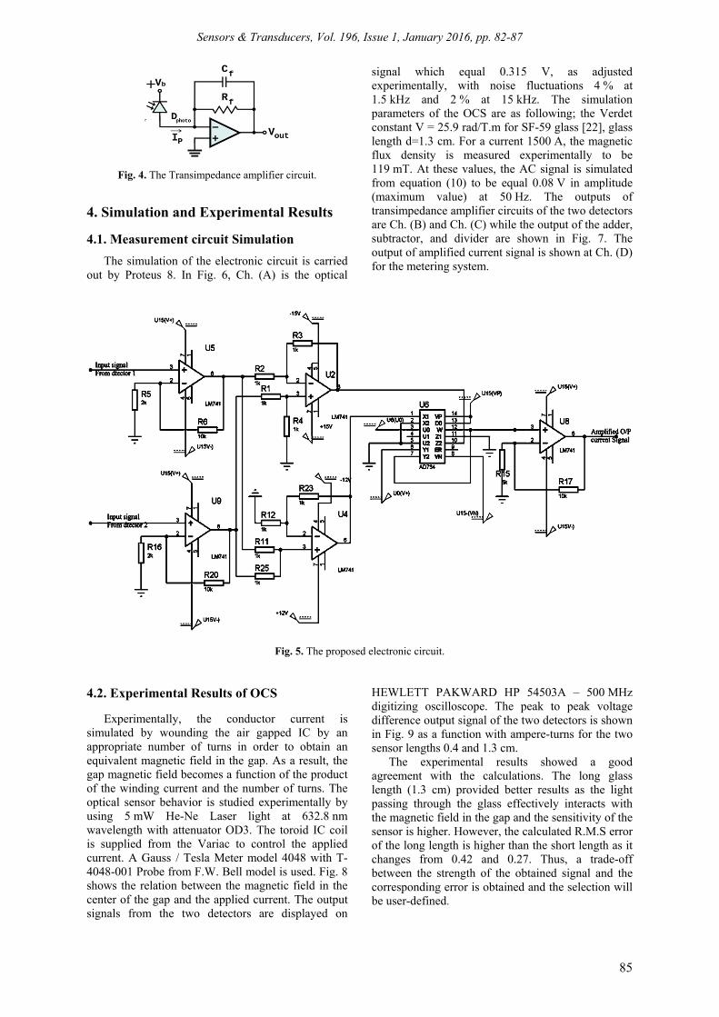
Fig. 4 introduces the equivalent circuit of the amplifier namely transimpedance amplifier. The reversed bias is used to convert the photodetected current Ip into Vout controlled by the resistor Rf. The circuit output is generated and simulated on the simulator program as an input to the proposed electronic circuit [19].
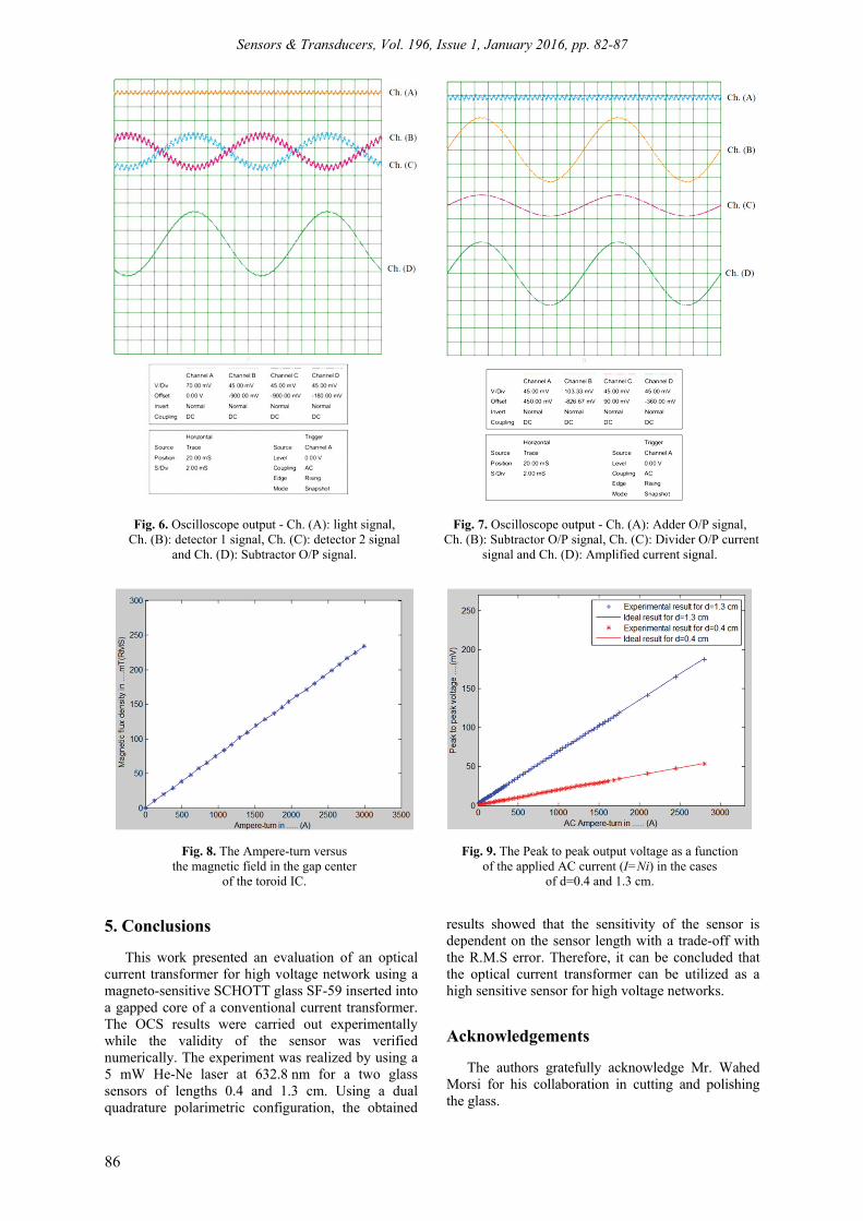
The simulation of the electronic circuit is illustrated in details in Fig. 5, showing the amplifier,
subtractor [20], adder, and divider [21]. The subtractor removes of the dc component and increases the current signal sensitivity. The adder circuit is used to get the dc component of the detected signal. The divider plays the main job to extract the electric signal corresponding to the measured current. Finally, the resulting signal is amplified for current measurements systems.
Sensors & Transducers, Vol. 196, Issue 1, January 2016, pp. 82-87
85
Fig. 4. The Transimpedance amplifier circuit.
4. Simulation and Experimental Results
4.1. Measurement circuit Simulation
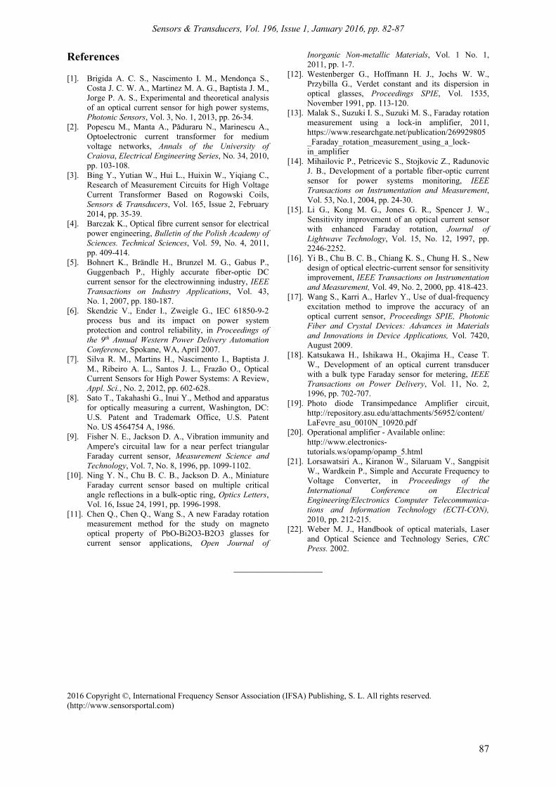
The simulation of the electronic circuit is carried out by Proteus 8. In Fig. 6, Ch. (A) is the optical
signal which equal 0.315 V, as adjusted experimentally, with noise fluctuations 4 % at 1.5 kHz and 2 % at 15 kHz. The simulation parameters of the OCS are as following; the Verdet constant V = 25.9 rad/T.m for SF-59 glass [22], glass length d=1.3 cm. For a current 1500 A, the magnetic flux density is measured experimentally to be 119 mT. At these values, the AC signal is simulated from equation (10) to be equal 0.08 V in amplitude (maximum value) at 50 Hz. The outputs of transimpedance amplifier circuits of the two detectors are Ch. (B) and Ch. (C) while the output of the adder, subtractor, and divider are shown in Fig. 7. The output of amplified current signal is shown at Ch. (D) for the metering system.
Fig. 5. The proposed electronic circuit.
4.2. Experimental Results of OCS
Experimentally, the conductor current is simulated by wounding the air gapped IC by an appropriate number of turns in order to obtain an equivalent magnetic field in the gap. As a result, the gap magnetic field becomes a function of the product of the winding current and the number of turns. The optical sensor behavior is studied experimentally by using 5 mW He-Ne Laser light at 632.8 nm wavelength with attenuator OD3. The toroid IC coil is supplied from the Variac to control the applied current. A Gauss / Tesla Meter model 4048 with T-4048-001 Probe from F.W. Bell model is used. Fig. 8 shows the relation between the magnetic field in the center of the gap and the applied current. The output signals from the two detectors are displayed on
HEWLETT PAKWARD HP 54503A – 500 MHz digitizing oscilloscope. The peak to peak voltage difference output signal of the two detectors is shown in Fig. 9 as a function with ampere-turns for the two sensor lengths 0.4 and 1.3 cm.
The experimental results showed a good agreement with the calculations. The long glass length (1.3 cm) provided better results as the light passing through the glass effectively interacts with the magnetic field in the gap and the sensitivity of the sensor is higher. However, the calculated R.M.S error of the long length is higher than the short length as it changes from 0.42 and 0.27. Thus, a trade-off between the strength of the obtained signal and the corresponding error is obtained and the selection will be user-defined.
Sensors & Transducers, Vol. 196, Issue 1, January 2016, pp. 82-87
86
Fig. 6. Oscilloscope output - Ch. (A): light signal, Ch. (B): detector 1 signal, Ch. (C): detector 2 signal
and Ch. (D): Subtractor O/P signal.
Fig. 7. Oscilloscope output - Ch. (A): Adder O/P signal,
Ch. (B): Subtractor O/P signal, Ch. (C): Divider O/P current signal and Ch. (D): Amplified current signal.
Fig. 8. The Ampere-turn versus
the magnetic field in the gap center of the toroid IC.
Fig. 9. The Peak to peak output voltage as a function
of the applied AC current (I=Ni) in the cases of d=0.4 and 1.3 cm.
5. Conclusions
This work presented an evaluation of an optical current transformer for high voltage network using a magneto-sensitive SCHOTT glass SF-59 inserted into a gapped core of a conventional current transformer. The OCS results were carried out experimentally while the validity of the sensor was verified numerically. The experiment was realized by using a 5 mW He-Ne laser at 632.8 nm for a two glass sensors of lengths 0.4 and 1.3 cm. Using a dual quadrature polarimetric configuration, the obtained
results showed that the sensitivity of the sensor is dependent on the sensor length with a trade-off with the R.M.S error. Therefore, it can be concluded that the optical current transformer can be utilized as a high sensitive sensor for high voltage networks.
Acknowledgements
The authors gratefully acknowledge Mr. Wahed Morsi for his collaboration in cutting and polishing the glass.
Sensors & Transducers, Vol. 196, Issue 1, January 2016, pp. 82-87
87
References [1]. Brigida A. C. S., Nascimento I. M., Mendonça S.,
Costa J. C. W. A., Martinez M. A. G., Baptista J. M., Jorge P. A. S., Experimental and theoretical analysis of an optical current sensor for high power systems, Photonic Sensors, Vol. 3, No. 1, 2013, pp. 26-34.
[2]. Popescu M., Manta A., Păduraru N., Marinescu A., Optoelectronic current transformer for medium voltage networks, Annals of the University of Craiova, Electrical Engineering Series, No. 34, 2010, pp. 103-108.
[3]. Bing Y., Yutian W., Hui L., Huixin W., Yiqiang C., Research of Measurement Circuits for High Voltage Current Transformer Based on Rogowski Coils, Sensors & Transducers, Vol. 165, Issue 2, February 2014, pp. 35-39.
[4]. Barczak K., Optical fibre current sensor for electrical power engineering, Bulletin of the Polish Academy of Sciences. Technical Sciences, Vol. 59, No. 4, 2011, pp. 409-414.
[5]. Bohnert K., Brändle H., Brunzel M. G., Gabus P., Guggenbach P., Highly accurate fiber-optic DC current sensor for the electrowinning industry, IEEE Transactions on Industry Applications, Vol. 43, No. 1, 2007, pp. 180-187.
[6]. Skendzic V., Ender I., Zweigle G., IEC 61850-9-2 process bus and its impact on power system protection and control reliability, in Proceedings of the 9th Annual Western Power Delivery Automation Conference, Spokane, WA, April 2007.
[7]. Silva R. M., Martins H., Nascimento I., Baptista J. M., Ribeiro A. L., Santos J. L., Frazão O., Optical Current Sensors for High Power Systems: A Review, Appl. Sci., No. 2, 2012, pp. 602-628.
[8]. Sato T., Takahashi G., Inui Y., Method and apparatus for optically measuring a current, Washington, DC: U.S. Patent and Trademark Office, U.S. Patent No. US 4564754 A, 1986.
[9]. Fisher N. E., Jackson D. A., Vibration immunity and Ampere's circuital law for a near perfect triangular Faraday current sensor, Measurement Science and Technology, Vol. 7, No. 8, 1996, pp. 1099-1102.
[10]. Ning Y. N., Chu B. C. B., Jackson D. A., Miniature Faraday current sensor based on multiple critical angle reflections in a bulk-optic ring, Optics Letters, Vol. 16, Issue 24, 1991, pp. 1996-1998.
[11]. Chen Q., Chen Q., Wang S., A new Faraday rotation measurement method for the study on magneto optical property of PbO-Bi2O3-B2O3 glasses for current sensor applications, Open Journal of
Inorganic Non-metallic Materials, Vol. 1 No. 1, 2011, pp. 1-7.
[12]. Westenberger G., Hoffmann H. J., Jochs W. W., Przybilla G., Verdet constant and its dispersion in optical glasses, Proceedings SPIE, Vol. 1535, November 1991, pp. 113-120.
[13]. Malak S., Suzuki I. S., Suzuki M. S., Faraday rotation measurement using a lock-in amplifier, 2011, https://www.researchgate.net/publication/269929805_Faraday_rotation_measurement_using_a_lock-in_amplifier
[14]. Mihailovic P., Petricevic S., Stojkovic Z., Radunovic J. B., Development of a portable fiber-optic current sensor for power systems monitoring, IEEE Transactions on Instrumentation and Measurement, Vol. 53, No.1, 2004, pp. 24-30.
[15]. Li G., Kong M. G., Jones G. R., Spencer J. W., Sensitivity improvement of an optical current sensor with enhanced Faraday rotation, Journal of Lightwave Technology, Vol. 15, No. 12, 1997, pp. 2246-2252.
[16]. Yi B., Chu B. C. B., Chiang K. S., Chung H. S., New design of optical electric-current sensor for sensitivity improvement, IEEE Transactions on Instrumentation and Measurement, Vol. 49, No. 2, 2000, pp. 418-423.
[17]. Wang S., Karri A., Harlev Y., Use of dual-frequency excitation method to improve the accuracy of an optical current sensor, Proceedings SPIE, Photonic Fiber and Crystal Devices: Advances in Materials and Innovations in Device Applications, Vol. 7420, August 2009.
[18]. Katsukawa H., Ishikawa H., Okajima H., Cease T. W., Development of an optical current transducer with a bulk type Faraday sensor for metering, IEEE Transactions on Power Delivery, Vol. 11, No. 2, 1996, pp. 702-707.
[19]. Photo diode Transimpedance Amplifier circuit, http://repository.asu.edu/attachments/56952/content/LaFevre_asu_0010N_10920.pdf
[20]. Operational amplifier - Available online: http://www.electronics-tutorials.ws/opamp/opamp_5.html
[21]. Lorsawatsiri A., Kiranon W., Silaruam V., Sangpisit W., Wardkein P., Simple and Accurate Frequency to Voltage Converter, in Proceedings of the International Conference on Electrical Engineering/Electronics Computer Telecommunica-tions and Information Technology (ECTI-CON), 2010, pp. 212-215.
[22]. Weber M. J., Handbook of optical materials, Laser and Optical Science and Technology Series, CRC Press. 2002.
___________________
2016 Copyright ©, International Frequency Sensor Association (IFSA) Publishing, S. L. All rights reserved. (http://www.sensorsportal.com)


![Current Transformer[1]](https://img.pdfslide.net/doc/110x75/577ca5521a28abea748b7c14/current-transformer1.jpg)