Embed Size (px)
Citation preview
8/11/2019 Research paper on muli-winglet analysis
http://slidepdf.com/reader/full/research-paper-on-muli-winglet-analysis 1/4
Experimental Investigation on the Effect of Multi-Winglets
International Journal of Mechanical & Industrial Engineering, Volume-1 Issue-1, 2011
43
Experimental Investigation on the Effect of Multi-Winglets
1Srikanth G, 2Surendra Bogadi1 PG Scholar; Dept. of Aeronautical Engineering, 2 Asst.Professor; Dept. of Aeronautical Engineering
1,2 Hindustan University, Chennai, India
E-mail : [email protected], [email protected]
Abstract —An extensive experimental study is conducted to examinethe potentiality of Multi-Winglets (similar to bird tip feathers) for the
reduction of Induced Drag, improved CL without increase in span of
aircraft wing. The model composed of a rectangular wing built from
NACA 0015 airfoil constituted of three winglets, which are small wings
without sweep & twist. The test conducted in subsonic wind tunnel at
flow speed 20m/s and placing the wing at angle of attack ranging from
-5 to +15 deg. And also the wing with no winglet (bare wing) and with
single winglet also tested in the same condition as in the case of three
winglets (multi-winglet). Wind tunnel balances provided lift
measurements and tuft flow visualization obtained wingtip vortex
information. The results show that multi-winglet system reduced
induced drag by 27.9% and improved CL by 26.5% compare to bare
wing.
Keywords-Induced drag;multi-winglet;
NOMENCLATURE
CL Coefficient of Lift
CDi Coefficient of Induced Drag
α Angle of Attack
AR Aspect Ratio
e Span Effeciency Factor
WWNW Wing with No Winglet
WWSW Wing with Single Winglet
WWMW Wing with Multi-Winglet
I. INTRODUCTIONEver since man started to think about flying, has striven
to imitate the shape and structure of a bird wing. Theresearchers began to look at the flying characteristics ofsoaring birds such as eagles, hawks, condors, vultures, andospreys. Each of these birds has wings with “pin” feathersat the ends that produce slotted wingtips. They found thatthe pin feathers worked to reduce drag, as well as beingused to provide roll control, in the same manner as aileronson aircraft.
The requirements of many modern aircraft missions aresuch that high values of aerodynamic efficiency must beobtained with aircraft having wings of relatively restrictedspan lengths. In many of these missions the aircraft mustoperate at relatively large values of the lift coefficient, andthe large induced drag associated with the small spanconsequently results in a rather low value for theoperational aerodynamic efficiency. In endeavoring toincrease the flight efficiency of such aircraft, it becomesnecessary to investigate more complex and unconventionalwing forms which might offer the possibility of securingappreciable reductions in the induced drag, subject to therestriction of limited span length. Such forms are to befound among the various non-planar lifting systems inwhich the lifting surfaces (wings) have an appreciablecurvature or extension in a vertical/horizontal plane
perpendicular to the direction of flight called Winglets.
The vortices produced at the wing –tips are unavoidable products by the lift presence, so it means the difficulties dueto force that support the aircraft in the air. These vorticesare responsible for the appearance of Induced Drag.
In cruise conditions the induced drag is responsible forapproximately 30% on entire drag and also 50% in high-liftconditions [1]. Hence to reduce the induced drag, wingletsare been used, bywhich fuel consumption goes down and range is extended,may achieve better lift.
Richard T Whitcomb [2] invented the Winglets in theearly 1970’s as a means by which wing lift-to-drag
performance could be increased. Indeed, his research in 1976indicated that winglets could reduce induced drag by twenty
percent, resulting in about nine percent better lift-to-drag
performance at 0.78 Mach for a specified wing loading. Inthe early days of the winglet era, only business jets adoptedwinglets, mostly due to aesthetic reasons. It shows the dragreduction [3] for the Gulfstream III, one of the pioneercorporate aircraft to adopt winglets. The flight test conductedat Mach number of 0.75 indicates a greater drag reductionthan the wind tunnel test had indicated. M. J. Smith et al [4-6] effort examined the potential of multi-winglets for thereduction of induced drag without increasing the span ofaircraft wings. A redefinition of multiple wingletconfigurations is proposed by U. La Roche and H.L. LaRochein [7] order to understand and facilitate exploiting themassive induced drag reductions of streamwise staggeredmultiple winglets, which, using the Prandtl-Munk vortexsheet model.
II. EXPERIMENTAL CONFIGURATIONExperiments have been carried out in the subsonic wind
tunnel facility available at the Aerodynamics Laboratory ofHindustan University, which has a test section size of 600mm x 600 mm x 2000 mm. at flow velocity 20 & 28m/s andangles of attack ranging from -5 to +15 degree.
Evaluation of the induced drag effects was made usingthe standard equation,
2
L
Di
C C
eARπ
=
Where aspect ratio (AR) =4, and e is approximately 0.94 for
WWNW and 0.907 for WWSW [8].
And e = 1.125 for WWMW-A and 0.9534 for WWMW-B
[9]
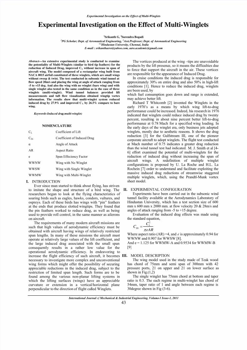
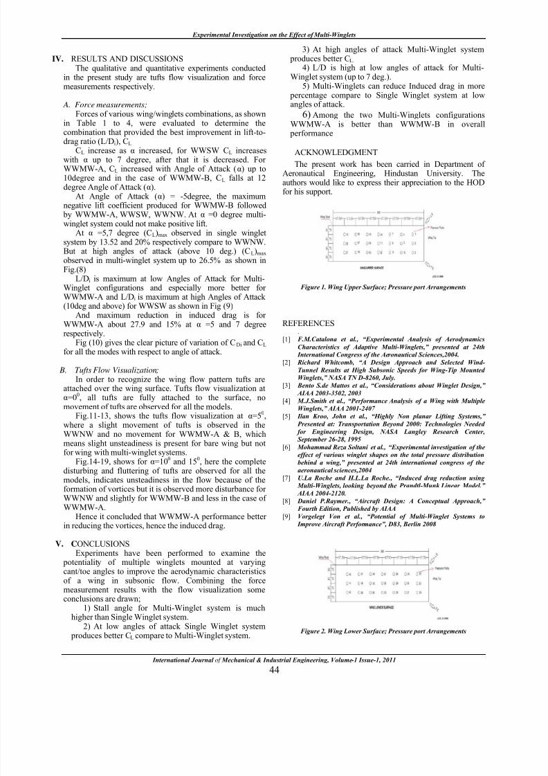
III. MODEL DESCRIPTIONThe wing model used in the study made of Teak wood
has chord of 75mm and semi span of 300mm with 42 pressure ports, 21 on upper and 21 on lower surface asshown in Fig.(1,2)
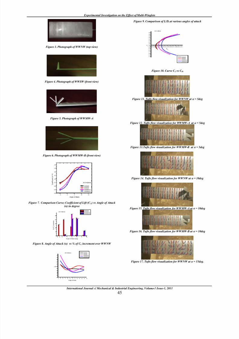
The single winglet has 75mm chord at bottom and taperratio is 0.3. The each regime in multi-winglet has chord of54mm, taper ratio of 1 and angle between each regime is30degree shown in Fig (3-6).
8/11/2019 Research paper on muli-winglet analysis
http://slidepdf.com/reader/full/research-paper-on-muli-winglet-analysis 2/4
Experimental Investigation on the Effect of Multi-Winglets
International Journal of Mechanical & Industrial Engineering, Volume-1 Issue-1, 2011
44
IV. RESULTS AND DISCUSSIONSThe qualitative and quantitative experiments conducted
in the present study are tufts flow visualization and forcemeasurements respectively.
A. Force measurements;Forces of various wing/winglets combinations, as shown
in Table 1 to 4, were evaluated to determine the
combination that provided the best improvement in lift-to-drag ratio (L/Di), CL
CL increase as α increased, for WWSW CL increaseswith α up to 7 degree, after that it is decreased. ForWWMW-A, CL increased with Angle of Attack (α) up to10degree and in the case of WWMW-B, CL falls at 12degree Angle of Attack (α).
At Angle of Attack (α) = -5degree, the maximumnegative lift coefficient produced for WWMW-B followed
by WWMW-A, WWSW, WWNW. At α =0 degree multi-winglet system could not make positive lift.
At α =5,7 degree (CL)max observed in single wingletsystem by 13.52 and 20% respectively compare to WWNW.But at high angles of attack (above 10 deg.) (CL)max observed in multi-winglet system up to 26.5% as shown in
Fig.(8) L/Di is maximum at low Angles of Attack for Multi-Winglet configurations and especially more better forWWMW-A and L/Di is maximum at high Angles of Attack(10deg and above) for WWSW as shown in Fig (9)
And maximum reduction in induced drag is forWWMW-A about 27.9 and 15% at α =5 and 7 degreerespectively.
Fig (10) gives the clear picture of variation of CDi and CL
for all the modes with respect to angle of attack.
B. Tufts Flow Visualization;In order to recognize the wing flow pattern tufts are
attached over the wing surface. Tufts flow visualization atα=0
0, all tufts are fully attached to the surface, no
movement of tufts are observed for all the models.Fig.11-13, shows the tufts flow visualization at α=50,
where a slight movement of tufts is observed in theWWNW and no movement for WWMW-A & B, whichmeans slight unsteadiness is present for bare wing but notfor wing with multi-winglet systems.
Fig.14-19, shows for α=100 and 15
0, here the complete
disturbing and fluttering of tufts are observed for all themodels, indicates unsteadiness in the flow because of theformation of vortices but it is observed more disturbance forWWNW and slightly for WWMW-B and less in the case ofWWMW-A.
Hence it concluded that WWMW-A performance betterin reducing the vortices, hence the induced drag.
V.
CONCLUSIONSExperiments have been performed to examine the
potentiality of multiple winglets mounted at varyingcant/toe angles to improve the aerodynamic characteristicsof a wing in subsonic flow. Combining the forcemeasurement results with the flow visualization someconclusions are drawn;
1) Stall angle for Multi-Winglet system is muchhigher than Single Winglet system.
2) At low angles of attack Single Winglet system produces better CL compare to Multi-Winglet system.
3) At high angles of attack Multi-Winglet system produces better CL.
4) L/D is high at low angles of attack for Multi-Winglet system (up to 7 deg.).
5) Multi-Winglets can reduce Induced drag in more percentage compare to Single Winglet system at lowangles of attack.
6) Among the two Multi-Winglets configurations
WWMW-A is better than WWMW-B in overall
performance
ACKNOWLEDGMENT
The present work has been carried in Department ofAeronautical Engineering, Hindustan University. Theauthors would like to express their appreciation to the HODfor his support.
Figure 1. Wing Upper Surface; Pressure port Arrangements
REFERENCES.
[1] F.M.Catalona et al., “Experimental Analysis of Aerodynamics
Characteristics of Adaptive Multi-Winglets,” presented at 24th
International Congress of the Aeronautical Sciences,2004.
[2] Richard Whitcomb, “A Design Approach and Selected Wind-
Tunnel Results at High Subsonic Speeds for Wing-Tip Mounted
Winglets,” NASA TN D-8260, July.
[3] Bento S.de Mattos et al., “Considerations about Winglet Design,”
AIAA 2003-3502, 2003
[4] M.J.Smith et al., “Performance Analysis of a Wing with Multiple
Winglets,” AIAA 2001-2407[5] Ilan Kroo, John et al., “Highly Non planar Lifting Systems,”
Presented at: Transportation Beyond 2000: Technologies Needed
for Engineering Design, NASA Langley Research Center,
September 26-28, 1995
[6] Mohammad Reza Soltani et al., “Experimental investigation of the
effect of various winglet shapes on the total pressure distribution
behind a wing,” presented at 24th international congress of the
aeronautical sciences,2004
[7] U.La Roche and H.L.La Roche., “Induced drag reduction using
Multi-Winglets, looking beyond the Prandtl-Munk Linear Model.”
AIAA 2004-2120.
[8] Daniel P.Raymer., “Aircraft Design: A Conceptual Approach,”
Fourth Edition, Published by AIAA
[9] Vorgelegt Von et al., “Potential of Multi-Winglet Systems to
Improve Aircraft Performance”, D83, Berlin 2008
Figure 2. Wing Lower Surface; Pressure port Arrangements
8/11/2019 Research paper on muli-winglet analysis
http://slidepdf.com/reader/full/research-paper-on-muli-winglet-analysis 3/4
Experimental Investigation on the Effect of Multi-Winglets
International Journal of Mechanical & Industrial Engineering, Volume-1 Issue-1, 2011
45
Figure 3. Photograph of WWNW (top view)
Figure 4. Photograph of WWSW (front view)
Figure 5. Photograph of WWMW-A
Figure 6. Photograph of WWMW-B (front view)
-5 0 5 10 15
-0.4
-0.3
-0.2
-0.1
0.0
0.1
0.2
0.3
0.4
At V=20m/s
C o e f f i c i e n t o f L i f t
Angle of Attack
WWNW
WWSW
WWMW-A
WWMW-B
Figure 7. Comparison Curve; Coefficient of Lift (C L ) vs Angle of Attack
( α ) in degree
4 6 8 10 12 14 16
0
5
10
15
20
25
5.6 6.3
11
20.9
21.9
26.5
20.7
11.2
1.51.4
20
13.5
5
At V=20m/s
% o
f C
L I n c r e m e n t
Angle of Attack (deg)
WWSW
WWMW-A
WWMW-B
Figure 8. Angle of Attack ( α ) vs % of C L increment over WWNW
4 5 6 7 8 9 10 11 12 13 14 15 16
25
30
35
40
45
50
55
60
65
70
75
At V=20m/s
L/Di
Angle of Attack
WWNW
WWSW
WWMW-A
WWMW-B
Figure 9. Comparison of L/Di at various angles of attack
-0.0010.0000.0010.002 0.0030.004 0.0050.0060.007 0.0080.009 0.010
-0.35
-0.30
-0.25
-0.20
-0.15
-0.10
-0.05
0.00
0.05
0.10
0.15
0.20
0.25
0.30
0.35
0.40
At V=20m/s
CL
CDi
WWNW
WWSW
WWMW-A
WWMW-B
Figure 10. Curve C L vs C Di
Figure 11. Tufts flow visualization for WWNW at α = 5deg
Figure 12. Tufts flow visualization for WWMW-A at α = 5deg
Figure 13.Tufts flow visualization for WWMW-B at α = 5deg
.
Figure 14. Tufts flow visualization for WWNW at α = 10deg
Figure 15. Tufts flow visualization for WWMW-A at α = 10deg
Figure 16. Tufts flow visualization for WWMW-B at α = 10deg
Figure 17. Tufts flow visualization for WWNW at α = 15deg.
8/11/2019 Research paper on muli-winglet analysis
http://slidepdf.com/reader/full/research-paper-on-muli-winglet-analysis 4/4
Experimental Investigation on the Effect of Multi-Winglets
International Journal of Mechanical & Industrial Engineering, Volume-1 Issue-1, 2011
46
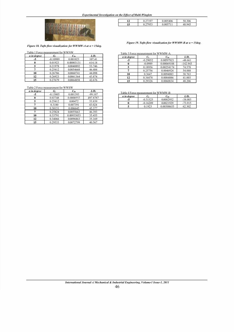
Figure 18. Tufts flow visualization for WWMW-A at α = 15deg.
Table 1 Force measurement for WWNW
α in degree C C Di L/Di
-5 -0.10989 0.001023 107.41
0 0.01923 0.00003131 614.18
5 0.21978 0.0040892 53.746
7 0.25412 0.0054668 46.484
10 0.26786 0.0060741 44.098
12 0.26923 0.0061364 43.874
15 0.27679 0.0064858 42.676
Table 2 Force measurement for WWSW
α in degree C C Di L/Di
-5 -0.13805 0.001393 -99.107
0 0.02748 0.0000552 497.8787
5 0.25412 0.00472 53.839
7 0.3180 0.007391 43.024
10 0.30151 0.006645 45.377
12 0.27197 0.005406 50.306
15 0.27953 0.005711 48.945
Figure 19. Tufts flow visualization for WWMW-B at α = 15deg .
Table 3 Force measurement for WWMW-A
α
in degree C L C Di L/Di -5 -0.29052 0.00597021 -48.661
0 -0.0989 0.00069188 -142.943
5 0.18956 0.00254174 74.578
7 0.25756 0.0046924 54.888
10 0.3647 0.0094083 38.763
12 0.34478 0.0084086 41.003
15 0.29326 0.0060834 48.206
Table 4 Force measurement for WWMW-B
α in degree C L C Di L/Di
-5 -0.31525 0.0082952 -38.003
0 -0.16209 0.0021929 -73.915
5 0.1923 0.00308655 62.302
7 0.25824 0.0055663 46.393
10 0.33791 0.00953053 35.45512 0.34066 0.0096863 35.169
15 0.29533 0.0072799 40.567