Embed Size (px)
Citation preview

RESEARCH PROJECT No. 28
DETERMINATION OF MECHANICAL PROPERTIES IN VARIOUS DUCTILE IRONS
AFTER SUBJECTING THEM TO LONG TERM ELEVATED TEMPERATURES
BY K.L. Hayrynen J.R. Keough B.V. Kovacs
SOCIETY
Issued by the Ductile Iron Society for the use of its Member Companies - Not for General Distribution
DUCTILE IRON SOCIETY 28938 Lorain Road
North Olmsted, Ohio 44070
(440)734-8040
J U N E 1999

DIS PROJECT # 28 FINAL REPORT
DETERMINATION OF MECHANICAL PROPERTIES IN VARIOUS DUCTILE IRONS
AFTER SUBJECTING THEM TO LONG TERM ELEVATED TEMPERATURES
K.L. HAYRYNEN J. R. KEOUGH B. V. KOVACS
Applied Process Inc Technologies Division 12238 Newburgh Road
Livonia, MI 48150

ABSTRACT
The study objective was to determine the mechanical property stability under elevated temperature conditions of a variety of cast irons and steels. It was not intended to show optimized properties for various grades of cast irons and steels and, in fact, the data presented should not be used in this way.
Tensile, impact and rotating bending fatigue properties of as-cast, normalized, quench and tempered, and austempered ductile iron and of normalized 1045 and carburized 8620 steels were measured at room temperature and after specimen exposure to elevated temperature(s).
The as-cast and normalized ductile iron along with the normalized 1045 steel did not exhibit significant changes in properties after an exposure to 600°F for 1000 hours. The austempered ductile irons (both Grades 1 and 5) maintained mechanical properties up to approximately 200°F below the austempering temperature. The tensile and impact properties for carburized 8620 steel decreased and then increased with elevated temperature exposure while the fatigue properties continually decreased.

EXPERIMENTAL PROCEDURE
Material Selection Seven groups of material were chosen for this study: 55-06 ductile iron, 70-03
ductile iron, quench & tempered ductile iron, ASTM 897 AD1 (both grades 1 and 5), 1045 steel and carburized 8620 steel.
Specimen PreparationMachining of Specimens Three inch diameter cylindrical bars of 80-55-06 Dura-~a$ were sectioned into
quarters for the machining of ductile iron specimens. All specimens were machined off- center to minimize any negative effects of centerline porosity on properties. The chemical composition of the Dura-~ar@ material is given in Table 1. All steel specimens were machined from 1-inch diameter bar stock. The specimens machined included 0.505" tensile bars, 0.25" dia rotating bending fatigue bars, un-notched Charpy and V-notched Charpy impact bars.
Table 1 Chemical Composition of 55-06 ~ u r a - ~ a r '
INTRODUCTION
Questions have been raised as to how well ductile irons and other engineering materials, such as steel, maintain their mechanical properties after being exposed to elevated temperatures for long periods of time. This information is critical to the design engineer since it may determine the maximum allowable operating temperature for a component. Furthermore, heat treated materials would be expected to be less likely to maintain their mechanical properties if the elevated temperature exposure met or exceeded the heat treatment temperature.
Objective of this study The objective of this study was to determine the effects of prolonged elevated
temperature exposure on the tensile, impact and fatigue properties of as-cast and heat treated ductile iron and some heat treated steels. It was not intended to show optimized properties for various grades of cast irons and steels and, in fact, the data presented should not be used in this way.

Heat Treatment The heat treat cycles utilized in this study are listed in Table 2. Machined
specimens (tensile , fatigue, and impact bars) were heat treated. All material except for the 8620 steel was heat treated in a commercial heat treat facility that uses integral quench batch hrnaces. Austenitizing was completed in a protective endothermic gas atmosphere. Quenching to a lower temperature (if needed) was done in a sodium nitritelpotassium nitrate salt bath. The 8620 steel was heat treated by a test laboratory which utilizes an industrial oil quench process.
Table 2 Heat Treat Cycles
' It should be noted that the heat treat cycle for the Q&T ductile iron was limited by the capabilities of the integral batch furnace systems. Oil quench systems would utilize a quench temperature in the range of 125150°F followed by tempering.
Material As-cast 55-06
(Dura ~ a r @ )
Normalized Ductile Iron
Q&T Ductile 1ron1
ASTM 897 AD1 (Grade 1)
ASTM 897 AD1 (Grade 5)
Normalized 1045
Carburized 8620
Heat Treat Cycle
none
1650°F - 2 hours air cool
1650°F - 2 hours 400°F - 3 minutes
temper 940°F - 2 hours
1650°F - 1.5 hours 725°F - 2 hours
1650°F - 1.5 hours 525°F - 4 hours
1650°F - 2 hours air cool
1700°F - 4 hours carbon potential 0.90%
oil quench 150°F temper 3 50°F for 1.5 hours

Mechanical Properties The mechanical properties documented for each group of materials includes:
tensile strength, yield strength, elongation, fatigue strength, V-notched Charpy impact energy, un-notched Charpy impact energy and hardness. The strength properties were determined in duplicates. Four impact bars were tested to determine the impact energy.
Rotating bending fatigue testing was performed at 7000 RPM. Testing continued until failure or a runout of lo7 cycles. A minimum of 6 fatigue bars were tested to determine stress versus cycles to failure (S/N) curves.
Elevated Temperature Exposure Elevated temperature exposure consisted of 1000 hours at temperature. All
materials were exposed to 600°F and Grade 1 ADI, Grade 5 AD1 and carburized 8620 were exposed to 200°F, 300°F, 400°F, 500°F and 600°F. The test matrix used for this study is given in Table 3.
Table 3 Test Matrix for Elevated Temperature Study
Material
55-06 (Dura ~ a r @ )
Normalized Ductile Iron
Q&T Ductile Iron
Grade 1 AD1
Grade 5 AD1
Normalized 1045
Carburized 8620
Exposure Temperatures
room, 600°F
room, 600°F
room, 600°F
room, 200°F 300°F, 400°F 500°F, 600°F room, 200°F 300°F, 400°F 500°F, 600°F
room, 600°F room, 200°F 300°F, 400°F 500°F, 600°F

X-ray Diffraction Analysis All x-ray diffraction (XRD) work on the austempered specimens was completed
using a Siemens D500 diffractometer (CuK, radiation at 50 kV and 35 mA) equipped with a graphite crystal monochromator. Ranges were step scanned with a step size of 0.06" 20 with a count time of 15 sec. The ranges scanned as well as the peaks scanned in each range are given in Table 4.
Table 4 Ranges Scanned and Peaks for X-ray Diffraction Analysis
I Scan Range I Peak(s) within 20 range ("20) I
I ferrite a(220) I The ratios of the areas of the peaks (ratios of integrated intensities) were used to
determine the volume fractions of austenite present in the austempered materials by using the following equation:
where I(hkl) is the integrated intensity for an austenite (y) or ferrite (a) peak and X is the volume fraction of the phase. The R factor is a term which includes the structure factor (F), multiplicity (P), Lorentz polarization factor (LP, modified for a graphite crystal monochromator), the temperature factor (e-2m) and the atomic volume of the unit cell (v).
Microstructural Examination Microstructural specimens were prepared from the grip sections of either tensile
or fatigue bars. Each specimen was etched with 5% Nital in preparation for photomicroscopy. All photomicrographs were taken at 400X magnification.

EXPERIMENTAL RESULTS AND DISCUSSION
Microstructures of Materials Representative microstructures of the room temperature specimens are given in
Figures 1 (a-g). Photomicrographs of the 600°F exposure specimens can be found in Figures 2 (a-g).
The microstructure of as-cast 55-06 ductile iron consisted of well-formed graphite nodules in a matrix of pearlite and ferrite. The approximate ratio of pearlite to ferrite was 63/27. There were no discernible differences in the microstructures of the as-cast and 600°F for 1000 hours samples, Figures l a and 2a.
The microstructure of normalized ductile iron consisted of well-formed graphite nodules in a matrix of predominantly pearlite. The ferrite content was less than 5%. There were no discernible differences in the microstructures of the as normalized and 600°F for 1000 hours samples, Figures lb and 2b.
The microstructure of salt-bath quench & tempered ductile iron consisted of well- formed graphite nodules in a matrix of tempered martensite. There were no discernible differences in the microstructures of the as quench & tempered and 600°F for 1000 hours samples, Figures l c and 2c.
The microstructures of Grade 1 AD1 before and after 600°F for 1000 hour exposure are shown in Figures Id and 2d, respectively. The before exposure microstructure consisted of well-formed graphite nodules in a matrix of coarse ausferrite. The after exposure microstructure consisted of well-formed graphite nodules and decomposed ausferrite.
The microstructures of Grade 5 AD1 before and after 600°F for 1000 hour exposure are shown in Figures l e and 2e, respectively. The before exposure microstructure consisted of well-formed graphite nodules in a matrix of fine ausferrite. The after exposure microstructure was similar in appearance to the salt-bath quench & tempered microstructure and consisted of well formed graphite nodules and decomposed ausferrite.
The microstructure of normalized 1045 steel consisted of ferrite and pearlite. The approximate ratio of ferrite to pearlite was 40160. There were no discernible differences in the microstructures of the normalized 1045 steel before and after the 600°F for 1000 hours exposure, Figures l f and 2f.
The microstructure of carburized 8620 steel consisted of tempered martensite. There were no discernible differences in the microstructures of the room temperature and 600°F for 1000 hours samples, Figures l e and 2e. (Note that one would expect to see a coarser microstructure in the 600°F sample as the carbides present in the tempered martensite should have coarsened.)
Mechanical Properties Mechanical property results (tensile strength, yield strength, percent elongation,
Charpy impact energy, hardness and estimated fatigue strengths) are given in Tables 5, 6, 8 -10. Average results are reported in these tables while the results for individual tensile and impact bars given in Appendix I. Complete fatigue results are also listed in Appendix I. Fatigue data plots (S/N curves) can be found in Figs. 3 - 10 and in Appendix 11.

(b) Normalized Ductile Iron (7003)
(c) Quench & Tempered Ductile Iron
Figure 1 : Photomicrographs of the room magnification. Specimens were
tem] : etcl
(d) Grade 1 AD1
serature microstructures taken at 400X ned with 5% Nital.

(el Grade 5 AD1
(f) Normalized 1045 Steel
(g) Carburized 8620 Steel
Figure 1 continued: Photomicrographs of at 400X magnificatio
the room temperature microstructures taken n. Specimens were etched with 5% Nital.

(b) Normalized Ductile Iron (7003)
(c) Quench & Tempered Ductile Iron
( 4 Grade 1 AD1
Figure 2: Photomicrographs of the 600°F c
400X magnification. Specimens ,ated temperature microstructures taken at re etched with 5% Nital.

(e) Grade 5 AD1
(f) Normalized 1045 Steel
(8) Carburized 8620 Steel
Figure 2 continued: Photomicrographs o taken at 400X magn
~f the 600°F elevated temperature microstructures ~ification. Specimens were etched with 5% Nital.

As-cast 55-06 - Room Temperature versus 600°F hoperties Examination of the mechanical properties in Table 5 for the as-cast material does
not show a significant change in UTS, yield, impact or hardness values with elevated temperature exposure. The average elongation decreases from 8.0% to 5.7% after exposure at 600°F, which is just under the specification level of 6% for 55-06 material. The typical un-notched Charpy impact energy range for 55-06 cast iron is 41 - 52 ft-lbs (55-70 J) depending on the volume fraction of pearlite present [I] while the hardness range per SAE J434C is 187-255 BHN. The values reported in Table 5 are within these ranges.
The S/N curves for both the room temperature and 600°F as-cast specimens are given in Fig. 3. The fatigue curves for both are similar with the fatigue strength at lo7 cycles estimated to be 45 ksi (3 10 m a ) .
Normalized Ductile Iron (70-03) - Room Temperature versus 600°F Properties The trends in mechanical properties for the normalized ductile iron are similar to
those shown for the 55-06 material. The UTS and yield do not change significantly with the elevated temperature exposure. There is a drop in elongation after exposure to 600°F, but the elongation reported still meets the 3% elongation specification of SAE J434C D-7003 cast iron. The hardness range for 70-03 cast iron is 241 - 302. A typical un- notched Charpy impact energy range is 26 - 30 ft-lbs (35-40 J) [I]. The hardness values reported in Table 5 are within the specification while the un-notched Charpy values exceed the typical values.
The SAJ curves for both the room temperature and 600°F normalized ductile iron specimens are given in Fig. 4. The estimated fatigue strengths at lo7 cycles are 43 ksi (296 MPa) and 41 ksi (283 MPa) for the room temperature and 600°F curves, respectively. As with the as-cast material, the fatigue strengths for both instances are similar.
Quench & Tempered Ductile Iron - Room Temperature versus 600°F Properties Two separate specifications for quench and tempered ductile iron exist - the
ASTM A536 120-90-02 grade and the SAE J434C DQ&T. The ASTM grade specifies UTS, yield and elongation while the SAE specification specifies martensite, but allows the hardness range to be dictated by the producer and/or end user with no UTS, yield or elongation specifications. The hardness target for this study was a 300 BHN. While the target hardness was met in a test coupon after a 2 hour temper at 940°F, the actual hardness measurements on the test specimens were higher, Table 5.
Once again, there is not a significant change in UTS or yield strength after exposure to 600°F. The average elongation increased from 4.0 to 4.8%. Un-notched impact energy values decrease slightly with exposure to the elevated temperature while the V-notched values are similar. Hardness values decreased from 378 to 33 5.
The S/N curves for both the room temperature and 600°F quench & tempered ductile iron are given in Fig. 5. There is a considerable amount of scatter present. The estimated fatigue strengths at lo7 cycles are 45 ksi (3 10 MPa) at room temperature and

Table 5: As-cast, Normalized and Q&T Ductile Iron Mechanical Properties
Notes: 1 Tensile results are an average from 2 test bars. 2 Impact energy levels are an average of 4 readings. 3 Fatigue strengths are estimated at lo7 cycles. 4 Q&T ductile iron tempered at 940°F (504°C). Target: hardness of 300 BHN As-cast ductile iron specification: 80-55-06, hardness range of 187-255 BHN. Normalized ductile iron specification: 100-70-03, hardness range of 24 1-302 BHN.
Q & p Ductile Iron
600°F (3 16°C)
172.0 / 1185..9
141.6 / 976.3
4.8
37.5 / 50.8
3.0 / 4.1
335
35 1 24 1
Tensile strength' (ksi / MPa)
Yield strength1 (ksi / MPa)
% ~ l o n ~ a t i o n '
unnotched Charpy Impact Energy
(ft-lb / J ) ~ V-notch Charpy Impact Energy
(ft-lb / J ) ~ Hardness (BHN)
Fatigue strength3 ksi / MPa
Q&T4 Ductile Iron
Rm Temperature
168.2 / 1159.7
140.4 / 968.0
4.0
35.8 / 48.5
3.0 14.1
378
45 / 310
As-Cast Ductile Iron
Rm Temperature
109.0 / 751.6
67.6 / 466.1
8.0
48.8 / 66.2
2.8 / 3.8
236
45 1310
As-Cast Ductile Iron
600°F (3 16°C)
104.2 / 718.4
64.3 / 443.3
5.7
49.0 / 66.4
3.2 / 4.3
223
45 / 310
Normalized Ductile Iron
Rm Temperature
143.6 / 990.1
86.7 / 597.8
6.0
43.5 / 59.0
2.8 / 3.8
275
43 / 296
Normalized Ductile Iron
600°F (3 16°C)
136.8 / 943.2
89.3 / 615.7
3.4
41.8 156.7
2.2 / 3.0
297
41 / 283

80 I I I I I I I @ l rn I I I I 1 1 1 1 I I I I I @ I v - - . - - 75 - 0 5506 - RT - - - -
m - -
70 7 5506 - 600°F - - -
m - - - -
65 - - D
- D
- D
60 - a - - - -
D
- 55 7 0. - - - - -
m -
50 -
(0 - D
- - 0 - - - 45 0 a 0-
D
m
m OD!! 40 OD-
D . - D
35 I I I I I 1 I 1 1 I I I I 1 I I I I 1 I I I 1 I 1 1
I o4 I o5 I o6 I o7
Cycles to Failure
Figure 3: Stress versus cycles to fai!ure for the 5506 room temperature and 600°F specimens. An arrow indicates the specimen did not fail.

- I I I I 1 1 1 1 I 1 1 1 I 1 I 1 1 I 1 I 1 1 1 I 1 ( 1 1 1 1
w -
m - - - - 0 normalized Dl - RT -
w -
w -
w a - normalized Dl - 600°F : -
w -
w -
w -
m - - -
9
- - m
- w
- - w - w
- 9
w -
w - - m -
w - - a
w
w . - m -
w -
w
w - - - - OW -
w -
m - - a . QP - - - - - - Ira -
w -
w
w -
1 I 1 1 1 1 1 1 I 1 I 1 1 1 1 1 1 1 1 I 1 1 1 I I 1 1 1 1
o I o5 I o6 I o7
Cycles to Failure
Figure 4: Stress versus cycles to failure for the normalized ductile iron room temperature and 600°F specimens. An arrow indicates the specimen did not fail.

Cycles to Failure
Figure 5: Stress versus cycles to failure for the quench & tempered ductile iron room temperature and 600°F specimens. An arrow indicates the specimen did not fail.

35 ksi (241 MPa) after exposure to 600°F. Because of the amount of scatter present, this difference in fatigue strength may or may not actually be 10 ksi (69 MPa). Testing a larger number of fatigue bars could address this issue.
Grade I ADI - Room Temperature versus 200°F, 300°F, 400°F, 500°F and 600°F Properties
The ASTM 897-90 specification for Grade 1 AD1 requires the minimal properties of 125-80-10 along with an un-notched Charpy impact energy of 75 fi-lbs at 72°F. The typical hardness range (not required) is 269 - 321 BHN.
Examination of the properties listed in Table 6 shows the following:
1. Tensile strengths are rather consistent for the Grade 1 AD1 from the RT specimens to the 600°F exposure.
2. The yield strength is relatively unchanged until the 600°F exposure during which it drops 10% from the RT level.
The average elongation declines slightly with elevated temperature exposure until 600°F when it drops to an average of 5.1% elongation - a 68% decrease from the room temperature level. It should be noted that both the RT and 300°F groups had one tensile bar that broke with an extremely low elongation level. Microstructural examination of each bar showed regions of porosity. It is believed that this porosity lead to the low levels of elongation. In this instance the measures that were taken to minimize the potential negative effects of centerline porosity in the Dura ~ a r @ were not successful.
4. The un-notched Charpy energy levels are highest at RT and 200°F and start to decrease after a 300°F exposure until taking a dramatic drop at 600°F. Even though a drop in energy level is occurring, the minimum specification of 75 A- Ibs is still met through exposure to 500°F.
5. The V-notched Charpy impact energy levels are consistent until a drop at 600°F. No specification exists for V-notched Charpy impact energy levels for ADI.
6. The BHN readings for all groups of specimens fell within the typical range of 269 - 321 BHN for Grade 1 ADI.
Work conducted by Nadkarni et al. [2]has shown similar trends in mechanical property performance with the aging of ADI. Their results indicate that UTS and yield strength are less sensitive than elongation to the decomposition of ausferrite with elevated temperature exposure. Boeri et al. [3] report similar findings. Their work found that aging at high temperatures causes minor changes in hardness and UTS, but will decrease elongation and impact properties.

Table 6: Grade 1 AD1 Mechanical Properties
Room 200°F 300°F 400°F 500°F 600°F Temperature (93°C) (1 49°C) (204°C) (260°C) (3 16°C)
Tensile strength' (ksi / MPa) 15 1.7 / 1042.5 159.0 / 1093.3 153.3 / 1057.0 156.3 / 1077.7 159.6 / 1100.4 149.1 / 1028.0
Yield strength1 (ksi / MPa) 117.2 / 808.1 117.6 / 810.9 121.1 / 835.0 123.4 / 850.8 123.7 / 852.9 106.4 / 733.6
% ~lon~a t ion ' 16.0~ 15.6 1 4 . 3 ~ 12.6 12.0 5.1
Unnotched Charpy Impact Energy 112.5 / 152.6 119.0 / 161.4 77.8 / 105.5 75.2 / 102.0 88.5 / 120.0 38.0 / 51.5
(ft-lb / J ) ~ V-notch Charpy Impact Energy 7.0 / 9.5 6.2 / 8.4 6.2 / 8.4 5.8 / 7.9 6.0 / 8.1 3.0 / 4.1
(ft-lb / J ) ~ Hardness
(BHN) 3 17 311 302 3 02 311 307
Fatigue strength3 ksi / MPa 49 / 338 48 / 331 55 / 379 461317 50 / 345 48 / 331
Notes: 1 Tensile results are an average from 2 test bars. 2 Impact energy levels are an average of 4 readings. 3 Fatigue strengths are estimated at 10' cycles. Note comments in Potential Property Limitations of the Experimental Results and Discussion.
ASTM 897-90 Grade 1 ADI: 125-80-10, 75 ft-lb unnotched Impact energy, typical hardness of 269-321 BHN

The fatigue results for the Grade 1 AD1 test group are listed in Appendix I. the S/N curves for the RT and 600°F specimens are shown in Fig. 6. The remaining S/N curves can be found in Appendix 11.
Examination of Fig. 6 shows no significant difference in fatigue strength at 10' cycles is present for the Grade 1 material after a 600°F exposure when compared to the RT material. In fact, all of the fatigue strengths for the Grade 1 S/N curves are similar. (Note Figs. 1 - 4 in Appendix 11.)
In addition to mechanical property testing, XRD analysis was completed on specimens removed from the gauge sections of tensile bars for the austempered material. The percent austenite is reported in Table 7. The amount of austenite starts to decline after an exposure to 300°F. By the time the elevated temperature exposure is completed at 60O0F7 a trace amount of austenite is left.
In a study completed by Trudel[4], 4 different alloys austempered at 363OC (685°F) were exposed to an elevated temperature of 250°C (482°F). The initial percent austenite varied from 30 - 35% for the 4 alloys. After an elevated temperature exposure for 1000 hours, the austenite content had decreased to 25%. When a similar group of samples was exposed to an elevated temperature of 350°C (662°F) for 1000 hours, all of
Table 7 X-ray Diffraction Results
Specimen Percent Austenite
Grade 1 - RT 50.1 Grade 1 - 200°F 49.0 Grade 1 - 300°F 43.3 Grade 1 - 400°F 40.1 Grade 1 - 500°F 39.3 Grade 1 - 600°F 1.75
Grade 5 - RT 15.2 Grade 5 - 200°F 16.9 Grade 5 - 300°F 13.5 Grade 5 - 400°F 10.2 Grade 5 - 500°F 8.1 Grade 5 - 600°F 0
the austenite had decomposed in 3 of the samples. The one in which austenite remained (-26%) had a higher Mo content (0.28) than the other 3 alloys. Lastly, an elevated temperature exposure at 400°C (752°F) resulted in the complete decomposition of the austenite within 20 hours for all 4 alloys; indicating that the decomposition of austenite is rapid at temperatures exceeding the austempering temperature.

Grade 1 ADI 1
m J - room temperature - . . 40 r -
- 600°F - - - m
- - 35 1 1 1 1 1 1 1 1 1 1 1 1 1 1 1 1 1 1 1 1 1 1 1 1 1 1 1 1 1 1
I o4 I o5 I o6 I o7
Cycles to Failure
Figure 6: Stress versus cycles to failure for the Grade 1 AD1 room temperature and 600°F specimens. An arrow indicates the specimen did not fail.

Both this work, as well as work completed by other researchers [2-41, suggests that AD1 should not be used at service temperatures that are close to or above the austempering temperature. The results in this study suggest that one could operate a Grade 1 part that was austempered at 725°F (385°C) at an elevated temperature up to and including 500°F (260°C) and maintain properties that exceed the minimum values of ASTM 897-90. However, the same part should not be operated at 600°F (3 16°C).
Grade 5 ADI - Room Temperature versus 200°F, 300°F, 400°F, 500°F and 600°F Properties
The ASTM 897-90 specification for Grade 5 AD1 requires the minimal properties of 230-185-NIA and an NIA for un-notched Charpy impact energy at 72°F where NIA refers to not applicable or not a part of the standard. The typical hardness range (not required) is 444 - 555 BHN.
Examination of the properties listed in Table 8 shows the following:
1. Tensile strengths are rather consistent for the Grade 5 AD1 from the RT to 500°F exposure, meeting the ASTM 897-90 minimum levels. At 600°F the tensile strength decreases almost 30% from its RT level and drops below the specification minimum of 23 0 ksi.
2. The trends in the yield strength for the Grade 5 AD1 are the same as the UTS results. The yield strength drops approximately 25% from the RT level after a 600°F exposure.
3. An elongation specification is not a requirement for Grade 5 ADI. The values in Table 8 are all minimal. However, it does appear that a slight increase in elongation is present after a 600°F exposure.
4. As with elongation, Charpy impact energy levels are not a part of the ASTM 897-90 specification. Both the un-notched and V-notched Charpy impact energy do not vary significantly from RT to a 600°F elevated temperature exposure.
5. The hardness values reported for the Grade 5 AD1 all meet the specification range of BHN 444 - 555 until the 600°F exposure occurs.
The fatigue results for the Grade 5 AD1 test group are listed in Appendix I. the SIN curves for the RT and 600°F specimens are shown in Fig. 7. The remaining S/N curves can be found in Appendix 11.
Examination of Fig. 7 indicates there is a significant difference in fatigue strength at lo7 cycles for the Grade 5 material after a 600°F exposure when compared to the RT material. The general trend is for the fatigue strength to increase with elevated temperature exposure. (Note Figs. E - H in Appendix 11.) A quench temperature of 525°F (274°C) was used to produce the Grade 5 ADI. It is possible that the

Table 8: Grade 5 AD1 Mechanical Properties
Room 200°F 300°F 400°F 500°F 600°F Temperature (93°C) (1 49°C) (204°C) (260°C) (3 16°C)
Tensile strength' (ksi / MPa) 245.4 / 1692.0 245.6 / 1693.4 238.0 / 1641.0 242.7 / 1673.4 239.0 / 1647.9 177.4 / 1223.5
Yield strength' (ksi / MPa) 201.5 / 1389.3 201.5 / 1389.3 205.1 / 1414.2 210.7 / 1452.8 209.7 / 1445.9 154.8 / 1067.3
% Elongation 2.2 2.0 1.4 1.8 1.1 3.0
Unnotched Charpy Impact Energy 38.0 / 51.5 36.0 / 48.8 36.0 / 48.8 39.5 / 53.6 30.0 / 40.7 39.2 / 53.2
(ft-lb / J ) ~ V-notch Charpy Impact Energy 3.8 / 5.2 3.5 / 4.7 4.0 / 5.4 2.5 / 3.4 2.5 / 3.4 4.0 / 5.4
(ft-lb / J ) ~ Hardness (BHN) 454 457 459 460 454 380
Fatigue strength3 ksi / MPa 25-30 / 172-207 25 / 172 30 I207 36 / 248 28 / 193 40 / 276
Notes: ' Tensile results are an average from 2 test bars. 2 Impact energy levels are an average of 4 readings. 3 Fatigue strengths are estimated at 10' cycles.
ASTM 897-90 Grade 5 ADI: 230-185-N/A, N/A unnotched Impact energy, typical hardness of 444-555 BHN

Grade 5ADI 4 0 room temperature 4
o I o5 I o6 I o7
Cycles to Failure
Figure 7: Stress versus cycles to failure for the Grade 5 AD1 room temperature and 600°F specimens. An arrow indicates the specimen did not fail.
microstructure contained some untempered martensite which tempered with elevated temperature exposure. If this did occur, one might expect to see an improvement in fatigue strength.
The percent austenite for the Grade 5 material is also reported in Table 7. The amount of austenite starts to decline after an exposure to 300°F (149°C). By the time the elevated temperature exposure is completed at 600°F (3 16"C), no austenite was detected. The XRD scans for this study were set up to optimize the determination of the amount of austenite present. If lower angle ranges had been scanned, the presence of martensite may have been able to be detected which could help to explain the increase in fatigue performance with elevated temperature exposure.
The properties of the Grade 5 AD1 that was exposed to elevated temperatures met the ASTM 897-90 minimums up to 500°F. However, the amount of austenite had decreased almost in half at 500°F. According to Table 7, the amount of austenite present starts to drop considerably after an exposure to a 300°F service temperature. A longer exposure time at temperatures above 300°F would most likely lead to more austenite decomposition. As a result, one should use caution before operating a Grade 5 component at service temperatures close to the austempering temperature. This study suggests that at Grade 5 AD1 component could operate at service temperatures up to and including 300°F (149°C).
Normalized 1045 - Room Temperature versus 600°F Properties Examination of the mechanical properties in Table 9 for the 1045 normalized
material does not show a significant change in UTS, yield strength, percent elongation, impact or hardness values with elevated temperature exposure. The un-notched Charpy impact energy levels could not be determined for this material because the bars bent during the test and did not fracture.
The S/N curves for the 1045 normalized material are shown in Fig. 8. The fatigue strength at lo7 cycles is approximately 5 1 ksi (352 MPa) for both conditions.
Carburized 8620 - Room Temperature, 200°F, 300°F, 400°F, 500°F and 600°F Properties
The mechanical properties for the carburized 8620 material are presented in Table 10 and Appendix I. Examination of this data shows the following:
1. The tensile strength of the carburized 8620 material decreases at 300°F and then starts to increase. After exposure at 600°F, the strength is slightly higher than that of the room temperature specimen.
2. Conclusions about the yield strength could not be made for this material. In many instances the test bar broke prior to yielding, thus yield strengths could not be determined.
3 . The elongation levels reported exhibit a trend similar to the UTS results. This trend is indicative of tempered martensite embrittlement, which can typically occur over the temperature range of 200-500°F.

Table 9: Normalized 1045 Mechanical Properties
Notes: 1 Tensile results are an average from 2 test bars. 2 Impact energy levels are an average of 4 readings. 3 Fatigue strengths are estimated at lo7 cycles.
1045 Normalized
600°F (3 16OC)
108.4 / 747.4
63.2 / 435.8
20.8
did not break
23.5 / 31.9
90
51 / 352
Tensile strength' (ksi / MPa)
Yield strength' (ksi / MPa)
% ~ l o n ~ a t i o n '
Unnotched Charpy Impact Energy
(ft-lb / J ) ~ V-notch Charpy Impact energy
(ft-lb / J ) ~ Hardness
(%) Fatigue strength3
ksi / MPa
1045 Normalized
Room Temperature
110.41761.2
67.0 / 462.0
20.6
did not break
18.8 125.5
92
51 1352


Table 10: Carburized 8620 Mechanical Properties
Heat Treat Cycle: Carburize at 1700°F (927OC) for 4 hours at carbon potential of 0.90%, oil quench 150°F (66OC), temper at 350°F ( 177°C) for 90 minutes.
Tensile strength1 (ksi / MPa)
Yield strength' (ksi / MPa)
% ~ l o n ~ a t i o n '
Unnotched Charpy Impact Energy
(ft-lb / J ) ~ V-notch Charpy Impact Energy
(ft-lb / J)' Surface ~ardness*
( R ) Case Depth
(inches) Fatigue Strength3
ksi / MPa Notes: I Tensile results are an average of 2 test bars. ' Impact energy levels are an average of 4 readings 3 Fatigue strengths are estimated at 10' cycles. 4 ND: unable to determine yield strength - or 1 bar broke before yield Specification: 0.025 - 0.035" effective case depth *surface hardness 58-62 R. The first hardness measurement for the case depth determination was made 0.0050" from the surface. Hardness readings at this location were greater than the surface hardness measurements.
Room Temperature
176.0 / 1213.5
155.6 / 1072.9
0.6
15.3 / 20.7
3.9 / 5.3
59.8 -
0.0467
>135 / 931
3 00°F (1 49°C)
147.2 / 1014.9
N D ~
<0.2
8.6 / 11.7
2.5 / 3.4
58.8
0.0389
110 1758
200°F (93 "C)
174.4 / 1202.5
140.6 / 969.4
0.3
14.4 / 19.5
3.5 14.7
60.0
0.0400
130 / 896
400°F (204°C)
15 1.9 / 1047.4
N D ~
0.2
10.5 / 14.2
2.0 / 2.7
51.2
0.0438
100 / 690
500°F (260°C)
195.8 / 1350.0
177.8 / 1225.9~
0.7
23.4 / 331.7
2.0 12.7
48.8 -
600°F (3 16°C)
183.6 / 1265.9
163.6 / 1128.0
6.5
92.0 / 124.8
18.9 / 25.6
- 44.0 -
0.0396
100 / 690
0.0104
95 / 655

4. The un-notched Charpy impact energy level decreases to about half of the RT level at 300°F. It then starts to increase and eventually increases to a level 6 times that of the RT level at 600°F.
5. The V-notched Charpy impact energy level decreases until 500°F. At 600°F it takes a dramatic increase as the un-notched levels did.
6. The effective case depth in inches was measured for each temperature. The case depths were similar until the 600°F which had a much lower case (0.0104 in) versus that at RT (0.0467 in).
7. Surface hardness levels met the specification of 59-62 R, up to a 300°F exposure before declining to a level one third of the RT level at 600°F.
The fatigue results for the carburized 8620 test group are listed in Appendix I. The SIN curves for the RT and 600°F specimens are shown in Figs. 9 and 10. The remaining S/N curves can be found in Appendix 11.
The RT specimens (in Fig. 9) all tested as runouts. The maximum stress level that the fatigue tester could accommodate was 135 ksi (93 1 MPa). Evidently the fatigue strength for his material is higher than a stress level of 135 ksi (93 1 MPa). Other researchers have reported fatigue strengths of up to 140 ksi (965 MPa) for carburized 8620 steel. [5]
The fatigue strength starts to decrease with exposure to elevated temperatures. The estimated fatigue strengths are 130 ksi (896 MPa), 110 ksi (758 MPa), 100 ksi (690 m a ) , 100 ksi (690 MPa) and 95 ksi (655 MPa) for the 200°F (93"C), 300°F (149"C), 400°F (204"C), 500°F (260°C) and 600°F (3 16°C) exposures respectively.
Material Comparisons The following material comparisons can be made for the materials tested in this
study:
1. The highest fatigue strengths at 10' cycles are reported for the carburized 8620 steel (95- 13 5+ ksi or 655-93 1+ MPa) followed by the normalized 1045 steel (51 ksi or 362 m a ) , Grade 1 AD1 (49-50 ksi or 338-345 MPa), 55/06 ductile iron (45 ksi or 3 10 MPa), normalized ductile iron (43 ksi or 296 MPa), Q&T ductile iron (35 ksi or 241 MPa) and Grade 5 AD1 (28-40 ksi or 193-276 m a ) .
2. The highest strength levels (both tensile and yield) are reported for the Grade 5 ADI, followed by the carburized 8620 steel, Q&T ductile iron, Grade 1 ADI, normalized ductile iron and a tie between 5506 and normalized 1045 steel.

Cycles to Failure
Figure 9: Stress versus cycles to failure for the carburized 8620 room temperature specimens. An arrow indicates the specimen did not fail.

Cycles to Failure
Figure 10: Stress versus cycles to failure for the carburized 8620 600°F specimens. An arrow indicates the specimen did not fail.

3 . The highest elongation levels are reported for the 1045 normalized steel followed by Grade 1 ADI, 5506 ductile iron, a tie between normalized and Q&T ductile iron, Grade 5 AD1 and 8620 carburized steel.
4. The highest un-notched Charpy impact energy levels are reported for the 1045 normalized steel followed by Grade 1 ADI, 5506 ductile iron, normalized ductile iron, Grade 5 ADI, Q&T ductile iron, 8620 carburized steel (excluding the 600°F specimens).
5. The highest V-notched Charpy impact energy levels are reported for the 1045 normalized steel followed by Grade 1 ADI, a tie between Grade 5 AD1 and 8620 carburized steel (excluding the 600°F specimens), a tie between 5506 ductile iron and Q&T ductile iron and normalized ductile iron.
Potential Property Limitations All test specimens used in this study were filly machined before heat treatment and
any applicable elevated temperature exposure. Thus, unintended specimen skin effects (carburization, decarburization, oxidation) resulting from the heat treatment process employed may result in less than optimum properties for an individual grade. As a case in point, a significantly higher endurance limit would be expected for a GRADE 1 AD1 than determined for the specimens in this study. These potential surface effects would not be expected to adversely effect any conclusions relative to property stability over the range of temperatures and times evaluated. However, the properties determined may be less than optimum for some of the individual material grades included in this study.
CONCLUSIONS
1. The investigated as-cast and normalized ductile irons and normalized steel maintained mechanical properties after long term exposure to elevated temperature (600°F). The investigated heat-treated ductile irons only maintained mechanical properties up to approximately 200°F below the heat treatment tempering temperature.
2. With an elevated temperature exposure at 600°F, significant changes in UTS, yield strength, impact energy, fatigue strength or hardness values do not occur for 5506 ductile iron. Similar trends are observed for normalized (7003) ductile iron except for a drop in elongation. Quench and tempered ductile iron maintains UTS, yield strength and V-notched Charpy energy levels with an exposure up to 600°F. Decreases in un-notched Charpy energy, hardness and fatigue strength are observed while elongation increases.

3. The UTS of Grade 1 AD1 does not vary significantly with an elevated temperature exposure of up to 600°F. Both yield strength and elongation follow the same trend as the UTS until 600°F before dropping 10% and 68%, respectively. Un-notched Charpy energy levels begin to decrease at 300°F and drop below the minimum ASTM 897-90 values at 600°F. V-notched Charpy energy levels hold until 600°F before dropping while hardness values remain within typical ranges for Grade 1 ADI. No significant difference in fatigue strength is observed.
4. For Grade 5 ADI, UTS and yield strengths are consistent until 500°F before dropping below ASTM 897-90 minimums at 600°F. Hardness levels behave in a similar manner with the values reported staying within typical ranges for Grade 5 AD1 until 600°F. Elongation and Charpy impact energy levels are not required for Grade 5 ADI. Fatigue strengths increase with exposure to elevated temperatures, suggesting that some residual martensite may be present in the structure that is tempering.
5. The amount of austenite in both Grades 1 and 5 AD1 starts to decline after an exposure to 300°F. After exposure at 600°F, only a trace amount is left for the Grade 1 material while none is present for Grade 5 ADI.
6. In this study, Grade 1 AD1 maintained ASTM 897-90 minimum properties for an elevated temperature up to and including 500°F (260°C). Grade 5 AD1 could be used at a service temperature up to and including 300°F (149°C).
7. UTS, yield strength, elongation, impact, hardness levels or fatigue strength did not change significantly for normalized 1045 steel after exposure to 600°F.
8. The UTS of carburized 8620 steel decreases with exposure to 300°F and then increases to a level slightly higher than the RT level at 600°F. Conclusions about the yield strength could not be made because the test bars broke prior to yielding. Both the un-notched and V-notched Charpy energy levels behave the same as the UTS except the increase at 600°F is very dramatic. The fatigue strength decreases with elevated temperature exposure.

RECOMMENDATIONS FOR FURTHER WORK
1. The ductile iron used in this study had a low alloy content. More work should be conducted to determine the effects of alloy content on the kinetics of tempering an ausferrite structure.
2. The increase in fatigue strength with an elevated temperature exposure for Grade 5 AD1 needs hrther investigation. Additional XRD analysis would be usefbl to hrther define the microstructural changes that are occurring with elevated temperature exposure.
3 . What would be the effects of an elevated temperature exposure on shot peened ADI?
REFERENCES
1. Internal data from Intermet-Wagner Castings.
2. G. Nadkami, S. Gokhale and J. D. Boyd, "Elevated Temperature Microstructural Stability of Austempered Ductile Irons", AFS Transactions, vol. 104, 1996, pp. 985-994. .
3. R. E. Boeri, J. M. Massone and J. A. Sikora, "Decomposition of High Carbon Austenite in ADI", AFS Transactions, vol. 104, 1996, pp. 133-137.
4. A. Trudel, "Service Temperature Sensitivity of AD1 Castings", submitted for publication for the DIS Keith Millis Symposium, October 1998.
5. ASM Handbook, Vol. 19, Fatigue and Fracture, 1996, p. 687
ACKNOWLEDGMENTS
The authors of this paper would like to thank the following for their invaluable assistance in the completion of this program: Terry Lusk for laboratory work and the Chrysler Technical Center for the heat treatment of the 8620 carburized steel.

TABLE OF CONTENTS APPENDIX I
Table 1 : As-cast, Normalized and Q&T Ductile Iron Tensile .and Impact Properties for Individual Test Bars
Table 2: Grade 1 Tensile and Impact Properties for Individual Test Bars
Table 3: Grade 5 Tensile and Impact Properties for Individual Test Bars
Table 4: 1045 Normalized Tensile and Impact Properties for Individual Test Bars
Table 5: 8620 Carburized Tensile and Impact Properties for Individual Test Bars
Table 6: Fatigue Results
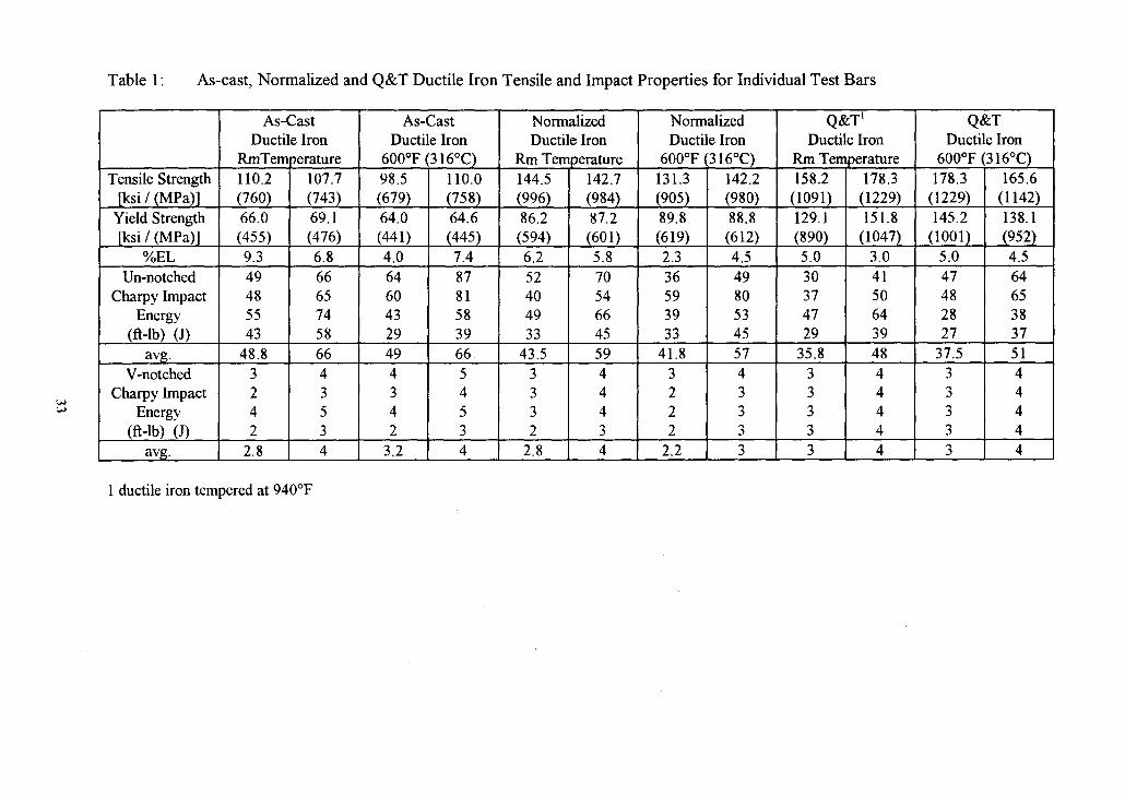
Table 1 : As-cast, Normalized and Q&T Ductile Iron Tensile and Impact Properties for Individual Test Bars
1 ductile iron tempered at 940°F
Tensile Strength [ksi 1 (MPa)]
Yield Strength [ksi 1 (MPa)]
%EL Un-notched
Charpy Impact Energy
(ft-lb) (J) avg .
V-notched Charpy Impact
Energy (ft-lb) (J)
avg .
As-Cast Ductile Iron
1 10.2 (760) 66.0 (455) 9.3 49 48 55 43
48.8 3 2 4 2
2.8
RmTem3erature 107.7 (743) 69.1 (476) 6.8 66 65 74 58 66 4 3 5 3 4
As-Cast Ductile Iron
600°F (3 16°C)
Q&T' Ductile Iron
Rm Temperature 98.5 (679) 64.0 (441) 4.0 64 60 43 29 49 4 3 4 2
3.2
158.2 (1091) 129.1 (890) 5.0 30 3 7 47 29
35.8 3 3 3 3 3
Q&T Ductile Iron
600°F (3 16°C) 110.0 (758) 64.6 (445) 7.4 87 8 1 5 8 39 66 5 4 5 3 4
Normalized Ductile Iron
Rrn Temperature 178.3
(1229) 151.8
(1047) 3 .O 4 1 5 0 64 3 9 48 4 4 4 4 4
178.3 (1229) 145.2
(1001) 5.0 47 4 8 28 2 7
37.5 3 3 3 3 3
Normalized Ductile Iron
600°F (3 16°C) 144.5 (996) 86.2 (594) 6.2 5 2 40 49 3 3
43.5 3 3 3 2
2.8
165.6 (1142) 138.1 (952) 4.5 64 65 38 3 7 5 1 4 4 4 4 4
131.3 (905) 89.8 (619) 2.3 3 6 5 9 3 9 3 3
41.8 3 2 2 2
2.2
142.7 (984) 87.2 (601) 5.8 70 54 66 45 59 4 4 4 3 4
142.2 (980) 88.8 (612) 4.5 49 80 5 3 45 5 7 4 3 3 3 3

Table 2: Grade 1 AD1 Tensile and Impact Properties for Individual Test Bars
**Elongation level decreased due to porosity observed optically near the fracture surface.
TensileStrength [ksi 1 (MPa)]
Yieldstrength [ksi / (MPa)]
%EL Un-notched
C harpy Impact Energy
(ft-lb) (J) avg .
V- notched Charpy Impact
Energy (ft-lb) (J)
avg .
Room Temperature
142.3 (98 1) 117.8 (8 1 2) *4.9* 109 1 1 0 134 97
112.5 7 8 7 6 7
160.2 (1 105) 117.2 (808) 16.0 148 149 182 131 152 9 11 9 8 9
200°F (93°C)
159.7 (1 101) 117.8 (8 1 2) 15.8 119 119 137 101 119 6 7 6 6
6.2
158.2 (1091) 117.3 (809) 15.3 161 16 1 186 137 16 1 8 9 8 8 8
3 00°F (149°C)
146.3 (1009) 120.8 (83 3) *4.3*
96 95 7 1 49
77.8 7 7 6 5
6.2 - - -
160.3 (1 105) 121.4 (837) 14 3 130 129 96 66 105 9 9 8 7 8
400°F (204°C)
159.6 (1 100) 125.0 (862) 15.0 9 1 7 1 74 6 5
75.2 7 6 6 4
5.8
153.0 (1055) 121.8 (840) 10.2 123 96 100 8 8 102 9 8 8 5 8
5 00°F (260°C)
600°F (3 16°C)
158.6 (1093) 123.5 (85 1) 11.4 9 1 105 80 78
88.5 6 6 6 6 6
150.4 (1037) 105.1 (725) 5.6 40 39 39 34 3 8 3 3 3 3 3
160.7 (1 108) 123.9 (8 5 4) 12.6 124 142 108 106 120 8 8 8 8 8
147.8 (1019) 107.6 (742) 4.6 54 5 3 5 3 46 5 1 4 4 4 4
4 -

Table 3: Grade 5 AD1 Tensile and Impact Properties for Individual Test Bars
Room 200°F 3 00°F 400°F 500°F 600°F Temperature (93°C) (149°C) (204°C) (260°C) (3 16°C)
TensileStrength 247.8 243.7 248.1 243.0 241.9 234.0 237.9 247.5 236.3 241.6 184.1 170.8 [ksi / (MPa)] (1709) (1680) (171 1) (1675) (1668) (1613) (1640) (1706) (1629) (1666) (1269) (1 178)
Yield Strength 201.0 202.0 202.0 201.0 207.1 203.1 211.2 210.2 211.2 208.2 156.1 153.6 [ksi / ( m a ) ] (1386) (1393) (1393) (1386) (1428) (1400) (1456) (1449) (1456) (1435) (1076) (1059)
%EL 2.8 1.5 2.7 1.3 1.6 1.2 1 .O 2.5 0.8 1.4 3.3 2.6 Un-notched 4 1 5 6 40 5 4 3 7 5 0 43 58 29 39 43 58
Charpy Impact 42 57 42 57 47 64 42 5 7 3 1 42 48 65 Energy 43 5 8 32 43 37 5 0 44 60 3 5 47 49 66
(ft-lb) (J) 26 3 5 3 0 4 1 23 3 1 29 3 9 25 3 4 17 23 avg . 3 8 5 1 36 49 3 6 49 39.5 54 3 0 4 1 39.2 5 3
V- notched 4 5 4 5 4 5 3 4 2 3 4 5 Charpy Impact 4 5 3 4 4 5 2 3 3 4 4 5
Energy 4 5 4 5 4 5 3 4 3 4 4 5 (ft-lb) (J) 3 4 3 4 4 5 2 3 2 3 4 5
avg. 3.8 5 3.5 5 4 5 2.5 4 2.5 4 4 5

Table 4: Normalized 1045 Tensile and Impact Properties for Individual Test Bars
Tensile Strength [ksi 1 ( m a ) ]
Yield Strength [ksi 1 ( m a ) ]
%EL Un-notched
Charpy Impact Energy
(ft-lb) (J) avg.
V-notched Charpy Impact
Energy (ft-lb) (J)
avg.
1045 Normalized
600°F (3 16°C) 11 1.2 (767) 64.0 (44 1) 20.7 did not
break
24 24 24 22
23.5
1045 Normalized
Rm Temperature 105.6 (72 8) 62.4 (43 0) 21.0 did not
break
3 2 3 2 32 30 32
110.4 (76 1) 67.7 (467) 20.3 did not
break
20 19 18 18
18.8
110.5 (762) 66.2 (4 5 6) 21.0 did not
break
2 7 26 24 24 2 5

Table 5: Carburized 8620 Tensile and Impact Properties for Individual Test Bars
ND: unable to determine yield strength - bar broke before yield
Tensile Strength p s i I (MPa)]
Yield Strength [ksi (MPa)]
%EL
Un-notched Charpy Impact
Energy (ft-lb) (J)
avg. V-notched
Charpy Impact Energy
(ft-lb) (J)
avg .
600°F (3 16°C)
188.3 (1298) 166.6
(1 149) 6.3
67.0 92.0 56.0 154.0 92.0 7.0 20.5 24.5 23.5 18.9
178.9 (1233) 160.6
(1 107) 6.7
9 1 125 76 209 125 9
2 8 33 32 26
Room Temperature
500°F (260°C)
174.9 (1 206) 153.5
(1058) 0.5
16.0 16.0 13.0 16.0 15.3 4.0 3.5 3.5 3.5 3.9
200°F (93°C)
199.3 (1374)
ND 1.2
27.0 17.5 25.0 24.0 23.4 2.5 1.5 2.0 2.0 2.0
177.2 (1 222) 157.7
(1087) 0.7
22.0 22.0 18.0 22.0 21.0 5.0 5.0 5.0 5.0 5.0
171.5 (1 182) 140.6 (969) 0.4
14.0 13.5 14.0 16.0 14.4 4.0 3 .O 4.0 3.0 3.5
192.4 (1327) 177.8
(1226) 0.2
37 24 3 4 32 3 2 3 2 3 3 3
177.4 (1223)
ND 0.2
19.0 18.0 19.0 22.0 19.0 5.0 4.0 5.0 4.0 5.0
3 00°F (149°C)
400°F (204°C)
138.3 (954)
ND <0.2
9.5 7.5 8.5 9.0 8.6 3 .O 2.5 2.5 2.0 2.5
150.3 (1036)
ND <0.2
10.0 10.0 12.0 10.0 10.5 2.0 2.0 2.0 2.0 2.0
156.2 (1077)
ND <0.2
13.0 10.0 11.0 12.0 12.0 4.0 3.0 3 .O 3.0 3 .O
153.5 (1058)
ND 0.3
14.0 14.0 16.0 14.0 14.0 3.0 3.0 3.0 3.0 3.0

Table 6 Fatigue Results
* Specimen did not fail.

* Specimen did not fail.

* Specimen did not fail

* Specimen did not fail

* Specimen did not fail,
8620 Carburized - 300°F 8620 Carburized - 300°F 8620 Carburized - 300°F 8620 Carburized - 300°F 8620 Carburized - 300°F
110 100 95 85 75
18,171,900* 16,996,400* 19,262,800* 17,055,200* 19,715,500*

8620 Carburized - 600°F 99 67,300 8620 Carburized - 600°F 98.5 130,400 8620 Carburized - 600°F 9 8 79,000 8620 Carburized - 600°F 97.5 33,854,300* 8620 Carburized - 600°F 95 18,29 1,700* 8620 Carburized - 600°F 85 14,699, loo* 8620 Carburized - 600°F 75 59,754,800*
*Specimen did not fail
7
TABLE OF CONTENTS APPENDIX I1
Figure IIA: Stress versus cycles to failure for the Grade 1 AD1 200°F specimens.
Figure IIB: Stress versus cycles to failure for the Grade 1 AD1 300°F specimens.
Figure IIC: Stress versus cycles to failure for the Grade 1 AD1 400°F specimens.
Figure IID: Stress versus cycles to failure for the Grade 1 AD1 500°F specimens.
Figure IIE: Stress versus cycles to failure for the Grade 5 AD1 200°F specimens.
Figure IIF: Stress versus cycles to failure for the Grade 5 AD1 300°F specimens.
Figure IIG: Stress versus cycles to failure for the Grade 5 AD1 400°F specimens.
Figure IIH: Stress versus cycles to failure for the Grade 5 AD1 500°F specimens.
Figure 111: Stress versus cycles to failure for the 8620 Carburized 200°F specimens.
Figure IIJ: Stress versus cycles to failure for the 8620 Carburized 300°F specimens.
Figure IIK: Stress versus cycles to failure for the 8620 Carburized 400°F specimens.
Figure IIL: Stress versus cycles to failure for the 8620 Carburized 500°F specimens.

80 - 1 w 1 m I m w u I I I I w 1 I # ( 1 I 1 1 w m m m l 1 1 1 1 - - - - w
- 75 r Grade 1 AD1 - 200°F 1 -
rn
- rn -
70 - - - .. - n - - .- cn 65 ; - x - u -
w
- - 60 r cn
- - 0
w
w
- L
- tj
- 55 r -
w
- - - - -
50 r - rn la - - - -
45 r &b
- w
(I
- - . 40 r -
w
- w - . -
35 1 1 1 1 1 1 1 1 1 1 1 1 1 1 1 1 1 1 1 1 1 1 1 1 1 1 1 1 1 1 1
I o4 I o5 I o6 I o7 Cycles to Failure
Figure IIA: Stress versus cycles to failure for Grade 1 AD1 200°F specimens. An arrow indicates the specimen did not fail.

Cycles to Failure
80 I 1 I 1 I 1 1 1 1 1 1 1 1 1 1 e m 1 I I I I 1 m u 1 1 I 1 1 - - - -
75 r Grade 1 AD1 - 300°F - . -
Figure IIB: Stress versus cycles to failure for Grade 1 AD1 300°F specimens. An arrow indicates the specimen did not fail.
70
9 cn 65 x 1
60 V) a, L
5 55
- r - - - - - - r - - - - - - a
r - - - - - - r
. dP . 50
45
40
35
0
- - - r Vb - 0
- - - - - - r - - - - - - - r - - - - - - -
1 1 1 1 1 1 1 1 k 1 1 1 1 1 a 1 1 1 1 1 1 1 1 1 1 1 1 1 1 1
I o4 I o5 I o6 I o7

80 - I I I I I u u m I I 1 v b e u m 1 I I D r n a I I 1 I v m - rn
. rn
75 = Grade 1 AD1 -400°F 2
Cycles to Failure
Figure IIC: Stress versus cycles to failure for Grade 1 AD1 400°F specimens. An arrow indicates the specimen did not fail.

Cycles to Failure
Figure IID: Stress versus cycles to failure for Grade 1 AD1 500°F specimens. An arrow indicates the specimen did not fail.


Cycles to Failure
Figure IIF: Stress versus cycles to failure for Grade 5 AD1 300°F specimens. An arrow indicates the specimen did not fail.

. m m m 1 m m m m m m m m m m I m w 1 1 m m u U r n ( 1 m w 1
w - - D Grade 5 AD1 - 400°F 1 - - - - - - - - - w
- w
- w
- - - - - - a - - - - a
w .I
w -
w -
w D - - - - w
- - a - - w
m
w - - - - - -
o** m
w a - - a -
w - - -
w .I - -
w m
w - - a -
1 1 1 1 1 1 1 1 1 1 1 1 1 1 1 1 1 1 1 1 a 1 1 a b 1 1 1 1 1
a a
Cycles to Failure
Figure IIG: Stress versus cycles to failure for Grade 5 AD1 400°F specimens. An arrow indicates the specimen did not fail.

w 1 1 1 1 1 1 1 1 1 1 1 1 1 1 1 1 1 1 1 1 1 1 1 1 1 1 I 1 1 1 - -
w - - Grade 5 AD1 - 500°F -
D - - - rn
w -
w - - -
0
w - - - - - - - - - - - - - - - - - - - - -
m D
- w
- - - w
- - - D
- - - w w 0
- - - - - - - I)
- 0
- . w -
Cycles to Failure
Figure IIH: Stress versus cycles to failure for Grade 5 AD1 500°F specimens. An arrow indicates the specimen did not fail.

Cycles to Failure
Figure 111: Stress versus cycles to failure for Carburized 8620 200°F specimens. An arrow indicates the specimen did not fail.


'dl 'dl
Cycles to Failure
Figure IIK: Stress versus cycles to failure for Carburized 8620 400°F specimens. An arrow indicates the specimen did not fail.

Cycles to Failure
Figure IIL: Stress versus cycles to failure for Carburized 8620 500°F specimens. An arrow indicates the specimen did not fail.


![Optimization of Carburized UNS G10170 Steel Process ... · engineering of components to improve the life and performance of parts used in automobiles and aerospace[1]. Mild steel,](https://img.pdfslide.net/doc/110x75/5ea5f487551c1260b453dfda/optimization-of-carburized-uns-g10170-steel-process-engineering-of-components.jpg)