Embed Size (px)
Citation preview
HSE Health & Safety
Executive
Safety of roll containers
Prepared by the Health and Safety Laboratory
for the Health and Safety Executive 2002
RESEARCH REPORT 009
HSE Health & Safety
Executive
Safety of roll containers
Brian Roebuck BSc Graham Norton MEng
Health and Safety Laboratory Broad Lane
Sheffield S3 7HQ
United Kingdom
Roll containers are half pallet-sized platforms, with four running castors and with a wire cage used to contain goods during transport. They may be used to transport goods in a lorry between a warehouse and a retail store for instance or within a supermarket to transport goods from the store room to the sales floor. This report will:
● identify the causes of roll container accidents;
● provide advice on roll container design to improve stability and to reduce the risk of accidents during handling. Both wheel and handle design are specifically included;
● provide advice on loading limits for roll containers, including load distribution. This will include information on manual forces needed to move roll containers and how the loading affects these forces; and
● produce recommendations on the use of tail lifts for use with roll containers.
A video has also been produced as a training aid for both enforcement officers and industry. This illustrates the factors involved in rollcage accidents and how these can be avoided.
This report and the work it describes were funded by the Health and Safety Executive (HSE). Its contents, including any opinions and/or conclusions expressed, are those of the authors alone and do not necessarily reflect HSE policy.
HSE BOOKS
© Crown copyright 2002
First published 2002
ISBN 0 7176 2535 4
All rights reserved. No part of this publication may bereproduced, stored in a retrieval system, or transmitted inany form or by any means (electronic, mechanical,photocopying, recording or otherwise) without the priorwritten permission of the copyright owner.
Applications for reproduction should be made in writing to: Licensing Division, Her Majesty's Stationery Office, St Clements House, 2-16 Colegate, Norwich NR3 1BQ or by e-mail to [email protected]
ii
CONTENTS
SUMMARY v
1. INTRODUCTION 1
2. INCIDENT DATA 2
2.1. Merseyside Accident Information Model 2
2.2. Sheffield Environmental Health Department2
2.3. Other Local Authorities4
2.4. Data from a major supermarket chain4
3. ROLL CONTAINER TYPES9
3.1. Nesting types9
3.2. Demountable roll containers 9
3.3. Construction 9
3.4. Ancillaries10
4. DESIGN AND SELECTION OF ROLL CONTAINERS11
4.1. Castors and Wheels11
4.2. Static stability13
4.3. Dynamic stability14
5. ROLL CONTAINER USE15
5.1. Assembling Roll Containers15
5.2. Empty roll containers16
5.3. Moving non-nested roll containers16
5.4. Moving nested roll containers16
5.5. Loading and unloading containers16
5.6. Pushing/pulling containers18
5.7. Handles19
5.8. Loading vehicles20
iii
5.9. Unloading vehicles21
5.10. General21
6. INSPECTION AND MAINTENANCE22
6.1. Inspection22
6.2. Maintenance22
7. TAIL LIFTS24
8. MANUAL HANDLING OF ROLL CONTAINERS 26
8.1. Starting forces26
8.2. Forces on slopes27
8.3. Operator pushing and pulling forces30
9. MECHANICAL HANDLING OF ROLL CONTAINERS32
10. CONCLUSIONS33
REFERENCES 35
FIGURES 36
APPENDIX 1 Derivation of force required to climb step 55
APPENDIX 2 Derivation of critical step height for overturning
56 APPENDIX 3 Derivation of velocity required to climb step
57 APPENDIX 4 List of contributors of information on roll
container use
List of contributors of information on roll containers
List of contributors of information on mechanical aids
58 APPENDIX 5 Dynamic testing
59
iv
SUMMARY
Roll containers are half pallet-sized platforms, with four running castors and with a wire cage used to contain goods during transport. They are also known as rollcages or roll pallets. They may be used to transport goods in a lorry between a warehouse and a retail store for instance or within a supermarket to transport goods from the store room to the sales floor. The use of roll containers reduces the need for manual handling and may allow goods to be taken straight from the warehouse to the shop floor. Since roll containers were introduced, they have become widely used, with several million estimated to be in use in the UK. The roll containers themselves need to be manually handled in most situations and, when fully loaded, can carry up to 500 kg of goods. Perhaps because of their wide use, they have also become a significant source of accidents, leading to sufficient concern in HSE and in Local Authorities for this project to be commissioned by HSE.
Objectives
The objectives of the project are as follows:
� to identify the causes of roll container accidents;
� to provide advice on roll container design to improve stability and to reduce the risk of accidents during handling. Both wheel and handle design will be specifically included
� to produce advice on loading limits for roll containers, including load distribution. This will include information on manual forces needed to move roll containers and how the loading affects these forces;
� to produce recommendations on the design and use of tail lifts for use with roll containers;
� to produce a video as a training aid for both enforcement officers and industry. This will illustrate the factors involved in rollcage accidents and how these can be avoided.
Main Findings
1. Roll containers are a convenient way of distributing goods and have both helped to speed up the distribution and reduce the need for manual handling of goods. A typical fully-loaded container can weigh up to 500 kg and, although the container is often mechanically handled at the point of dispatch, it must itself be manually handled at its destination. The destination could be a modern superstore, with smooth and level floors throughout, or a high street shop, where the handling of the container may involve movement on slopes, across changes in floor level or floor surface. At most destinations, there will be congested back of store/shop areas where manoeuvering of a 500 kg load on 125 mm castors is not easy. We believe that it is important, at the point of loading, to consider risks which the container might pose throughout its journey and at all destinations where it will be manually handled. Where there are too wide a variety of destinations to consider individually, grouping of similar destinations or a presumption of the worst case would be best practice.
2. Comprehensive statistics on roll container accidents are not available but we have collected sufficient information to illustrate that they are involved in a large number of accidents. These represent:
v
� 3% of reported RIDDOR reportable accidents in Sheffield
� 30% of manual handling accidents to sales assistants referred to the Royal Liverpool University Hospital
� 35% of reported accidents in one sector of a major distribution company
� 20% of reported accidents in a major supermarket chain.
3. The most important design features which would help reduce roll container accidents are:
� larger diameter wheels, to reduce pushing/pulling forces and to make these less sensitive to imperfections in the surfaces on which containers are used
� the incorporation of handles, to move fingers and hands away from the corners of containers where they are vulnerable to impact and trapping damage and, when cages are pulled, to move feet further away from the container and reduce the risk of foot injuries
� marked load height limits, to enable the operator to have a clear view when containers are pushed.
� castors close to corners to improve stability
4. When roll containers are used on flat, level surfaces, the maximum forces to move and manoeuver containers will typically be 2 % of the load with the wheels aligned with the direction of travel and 5% of load with the wheels at right angles to the direction of travel. In the worst case, with the heaviest load of 500 kg, starting forces of around 250 N can be expected. These forces are just within the the maximum we would expect male operators to be asked to handle without a risk assessment but above the force of 160 N we would expect female operators to be asked to handle without a risk assessment. With uneven surfaces, the maximum starting force could be expected to rise to 10 % of the load. It is clear that the movement of heavily loaded roll containers is likely to place lone operators at risk of injury, even on level surfaces.
5. Where containers need to be handled on slopes, the operator will need to overcome a force proportional to the load and to the slope angle. For example, for a roll container with a mass of 400 kg and a slope of 1 in 12 (4.8O) the force needed to be applied by the operator would be 330 N, well above the force we might expect a man to handle and almost double the force we might expect a woman to handle. Clearly, slopes of this magnitude present a potential hazard. Suggested load limits for a range of slope angles are included at Section 8.2.3. A further problem with slopes is that they make it more likely that the operator could slip. This should not be a problem on concrete surfaces but could be a problem on low friction surfaces such as steel. In general, we would expect a risk assessment to be carried out where roll containers need to be manually handled on slopes and that two operators would be needed to reduce manual handling forces within acceptable limits.
6. Although pushing of roll containers is generally preferred, in practice both pushing and pulling are necessary in most situations. Where pulling is widely done, we would expect the use of inbuilt or detachable handles to be considered as a means of removing hands and fingers from the corners of the containers where they are liable to be trapped and for moving feet away from the castors which cause foot injuries.
vi
7. Loading and unloading of lorries, particularly using tail lifts, is a significant source of accidents, often causing the most serious injuries. Accidents can be reduced by
� loading and unloading on flat ground or at purpose-designed bays
� proper restraint of roll containers in the vehicle during loading and unloading
� well maintained tail lifts with side and end ramps or stops and restraining straps to ensure that roll containers are properly restrained
� well planned procedures which ensure that workers are not in the hazard zone during operation of tail lifts etc and which ensure that riding loaded tail lifts is not necessary
8. A large proportion of injuries are to fingers and feet and the severity of these injuries could be significantly reduced if roll container operators wore safety shoes and industrial gloves. The use of gloves may not be practicable and is no substitute for the use of handles but we were surprised that safety footwear was not more widely used.
9. The increasing use of mechanical handling of roll containers should lead to a reduction in manual handling and to a consequent reduction in accidents. Mechanical handling can produce an increase in the damage to containers, usually at the distribution depot where the containers are loaded. It is important, therefore, that mechanical handling is accompanied by rigorous inspection and maintenance regimes to avoid problems with damaged containers at loaded container destinations.
vii

viii
1. INTRODUCTION
Roll containers are half pallet-sized platforms, with four running castors and with a wire cage used to contain goods during transport. They are also known as roll cages or roll pallets. They may be used to transport goods in a lorry between a warehouse and a retail store for instance or within a supermarket to transport goods from the store room to the sales floor. The use of roll containers reduces the need for manual handling and may allow goods to be taken straight from the warehouse to the shop floor. Since roll containers were introduced, they have become widely used, with several million estimated to be in use in the UK. The roll containers themselves need to be manually handled in most situations and, when fully loaded, can carry up to 500 kg of goods. Perhaps because of their wide use, they have also become a significant source of accidents, leading to sufficient concern in HSE and in Local Authorities for this project to be commissioned by HSE. The objectives of the project are as follows:
� to identify the causes of roll container accidents;
� to provide advice on roll container design to improve stability and to reduce the risk of accidents during handling. Both wheel and handle design will be specifically included;
� to produce advice on loading limits for roll containers, including load distribution. This will include information on manual forces needed to move roll containers and how the loading affects these forces;
� to produce recommendations on the design and use of tail lifts for use with roll containers;
� to produce a video as a training aid for both enforcement officers and industry. This will illustrate the factors involved in rollcage accidents and how these can be avoided.
This report contains the results of the work outlined above. The training video is provided seperately.
1
2. INCIDENT DATA
Incident data has been collected from a number of sources. Whilst not all the different sets of data considered contain very large number of incidents, they have enabled the major causes of roll container incidents to be identified.
2.1 MERSEYSIDE ACCIDENT INFORMATION MODEL
Researchers from Liverpool University used a computer based accident information system, the Merseyside Accident Information Model (MAIM) to analyse the information on sets of occupational injuries including manual handling incidents reported to the Royal Liverpool University Hospital during the 1990’s. MAIM records all of the available information on the sequence of events in an incident, what activities were taking place, body movements and location, as well as information about the injured person.
The work enabled estimates to be made of the significance of manual handling injuries from various causes. Roll containers were not specifically mentioned in the work, but trolleys were. It was shown that trolleys were the most frequently listed first event object in manual handling injuries. For sales assistants, ‘trolleys’ were involved in 6 out of 20 manual handling injuries, ie 30%. The researchers have estimated that for all occupations, trolleys are involved in 3300 reportable (RIDDOR) manual handling injuries per annum in England. They further estimate that this represents 8% of the total reportable manual handling injuries in England and approximately 3% of all reportable incidents. These estimates are based purely on attendances at hospital accident and emergency departments.
The description ‘trolley’ can cover various mechanical aids, however, since roll containers are so numerous it is likely that many of the trolley incidents recorded were in fact roll container incidents. The descriptions listed for events involved in the trolley incidents were as follows;
trolley accidentally struck door trolley broke wheel broke or collapsed door fell on your thumb/finger floor surface jerked trolley you missed edge of tailboard you missed edge of lift case (food) slid off trolley wheel (heavy) slipped on trolley trolley (metal) struck trolley trolley struck box (metal) trolley (metal) struck your foot trolley struck unlisted ground surface you struck cabinet (filing) trolley struck pallet wheel stuck or jammed hole in ground wheel stuck or jammed hole in floor wheel stuck or jammed hole in floor wheel stuck or jammed door wheel stuck or jammed lift door/gate your foot tilted trolley trolley unexpectedly moved your ankle were struck by gate (heavy) you were trapped by trolley (metal) you unintentionally stepped on plastic component.
These descriptions are closely echoed by descriptions of roll container accidents from other sources of data, as detailed below.
2.2 SHEFFIELD ENVIRONMENTAL HEALTH DEPARTMENT
Sheffield Environmental Health Department were asked to help with the collection of data on roll container incidents. HSL were given access to the RIDDOR reports for Sheffield for the
2
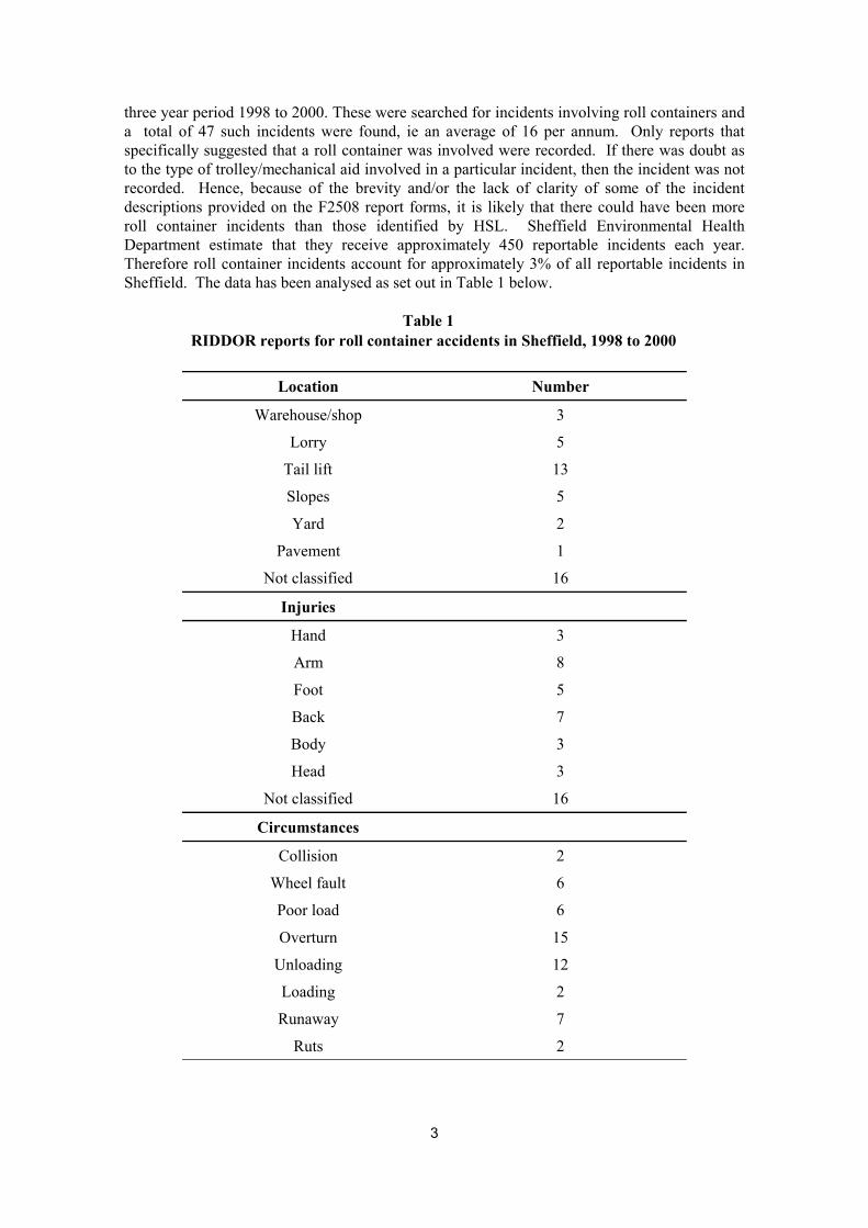
three year period 1998 to 2000. These were searched for incidents involving roll containers and a total of 47 such incidents were found, ie an average of 16 per annum. Only reports that specifically suggested that a roll container was involved were recorded. If there was doubt as to the type of trolley/mechanical aid involved in a particular incident, then the incident was not recorded. Hence, because of the brevity and/or the lack of clarity of some of the incident descriptions provided on the F2508 report forms, it is likely that there could have been more roll container incidents than those identified by HSL. Sheffield Environmental Health Department estimate that they receive approximately 450 reportable incidents each year. Therefore roll container incidents account for approximately 3% of all reportable incidents in Sheffield. The data has been analysed as set out in Table 1 below.
Table 1 RIDDOR reports for roll container accidents in Sheffield, 1998 to 2000
Location Number
Warehouse/shop 3
Lorry 5
Tail lift 13
Slopes 5
Yard 2
Pavement 1
Not classified 16
Injuries
Hand 3
Arm 8
Foot 5
Back 7
Body 3
Head 3
Not classified 16
Circumstances
Collision 2
Wheel fault 6
Poor load 6
Overturn 15
Unloading 12
Loading 2
Runaway 7
Ruts 2
3
The significance of this set of data is that it provides a complete picture for a known population, ie approximately 480,000 people, over a period of 3 years. Of particular note are the number of incidents involving lorries and tail lifts, the number of overturned trolleys and the number of incidents whilst unloading. This suggests that overturning trolleys on or from lorries or tail lifts is a particular problem. There are also a number of incidents on slopes or ramps.
2.3 OTHER LOCAL AUTHORITIES
As a preliminary to this research project, HSE’s Local Authority Unit invited local authorities to provide examples of roll container incidents. These were then followed up during the project, and other examples obtained. A total of 50 responses were received, including details of 78 specific incidents. Some responses were more general, Blackpool Borough Council, for example, had had 132 over 3 day injuries in 1994/5 of which ‘an unnaturally high number were manual handling injuries, over 30% of which being attributable to roll cages’. Comments included the following circumstances as being examples of the causes of accidents:
� wheel collapses leading to toppling; � wheels jamming due to entanglement with cling film; � straps breaking; � over-height stacking leading to product toppling; � overturns at concrete expansion joints; � defective roll containers not being taped; � staff climbing into or over roll containers.
Where specific incidents were detailed, these were analysed as shown in Table 2, overleaf.
The most common injury site is foot/ ankle and the most common sites for the incidents to take place are lorries, tail lifts and on slopes or ramps. Again, overturning of the containers and loading/unloading vehicles are the most common circumstances with a significant number of runaways.
2.4 DATA FROM A MAJOR SUPERMARKET CHAIN
Details of roll cage accidents for the year 1999/2000 were supplied to HSL by one of the major supermarket chains. Roll cage accidents represented 453 of 2292 3-day accidents, that is, 20% of the total. A total of 426 incidents were analysed. The results are set out in Table 3.
4
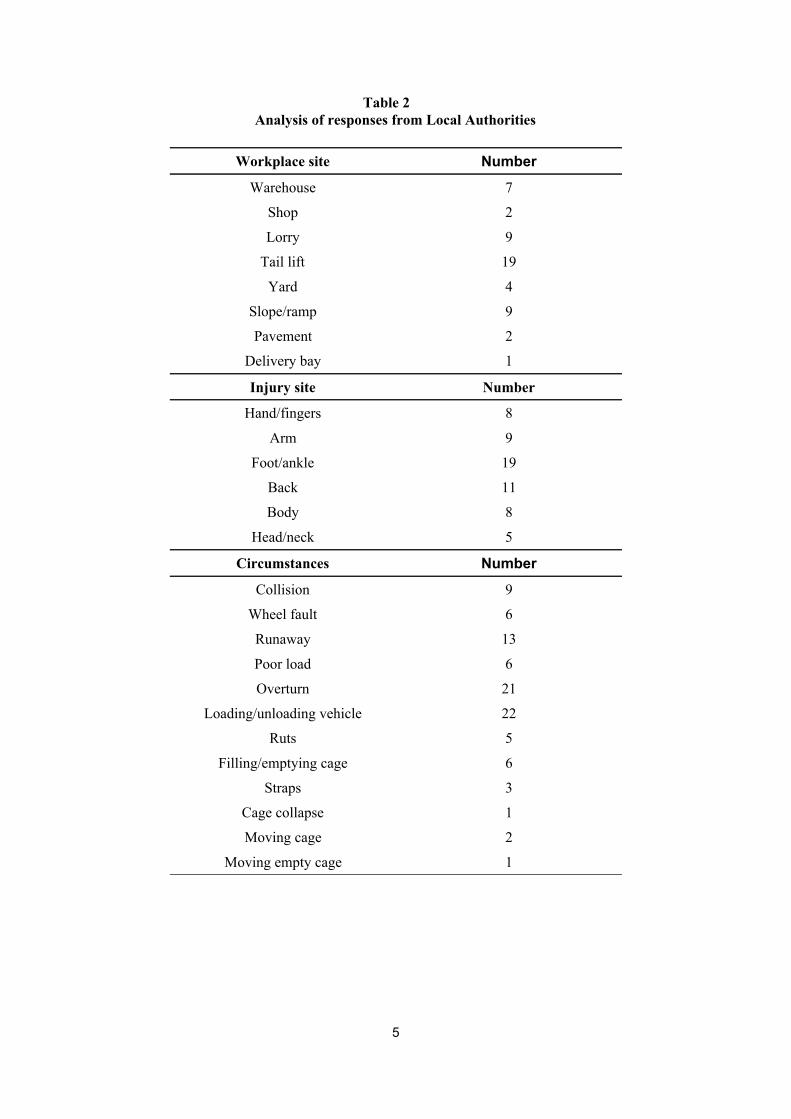
Table 2 Analysis of responses from Local Authorities
Workplace site Number Warehouse 7
Shop 2
Lorry 9
Tail lift 19
Yard 4
Slope/ramp 9
Pavement 2
Delivery bay 1
Injury site Number
Hand/fingers 8
Arm 9
Foot/ankle 19
Back 11
Body 8
Head/neck 5
Circumstances Number Collision 9
Wheel fault 6
Runaway 13
Poor load 6
Overturn 21
Loading/unloading vehicle 22
Ruts 5
Filling/emptying cage 6
Straps 3
Cage collapse 1
Moving cage 2
Moving empty cage 1
5
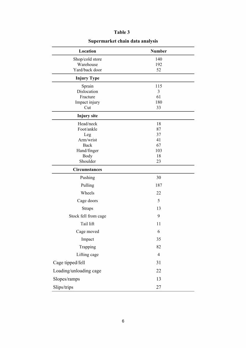
Table 3
Supermarket chain data analysis
Location Number
Shop/cold store 140 Warehouse 192
Yard/back door 52
Injury Type
Sprain 115 Dislocation 3
Fracture 61 Impact injury 180
Cut 33
Injury site
Head/neck 18 Foot/ankle 87
Leg 37 Arm/wrist 41
Back 67 Hand/finger 103
Body 18 Shoulder 23
Circumstances
Pushing 30
Pulling 187
Wheels 22
Cage doors 5
Straps 13
Stock fell from cage 9
Tail lift 11
Cage moved 6
Impact 35
Trapping 82
Lifting cage 4
Cage tipped/fell 31
Loading/unloading cage 22
Slopes/ramps 13
Slips/trips 27
6
Not surprisingly, a large proportion of the stated injuries were to hands and fingers, 26%, and feet and ankles, 22%. The fractures were fingers, trapped between container and container or container and door, and toes run over by a container. A high proportion of the incidents were associated with pulling containers, 44%, compared with pushing, only 7%. The pulling injuries were typically of the following types:
a) foot and ankle injuries when the container was pulled onto the operator, without other intervention;
b) hand and finger injuries when the cage was pulled into another cage or a door frame, with the operator’s hand and fingers presumably caught between the corner of the container and the object struck;
c) sprains/strains caused when the container was initially being moved or being pulled across an uneven floor or gap/step in the floor. The gaps/steps included those between lorries and tail lifts, lifts and landings, and between ramps and level surfaces.
d) containers overturning when the wheels met an obstruction in the floor;
e) slipping and tripping.
Wheel incidents were usually due to wheels jamming or becoming jammed in gaps in the floor. Cage door incidents included doors falling off or opening to strike the operator. Strap incidents included straps breaking or getting caught as the container passed other containers. Stock falling was normally from the top of a container onto the operator.
Tail lift incidents were significantly fewer than in the Local Authority surveys. This may be because they resulted in the container overturning and were therefore amongst the more serious incidents recorded. The Local Authority surveys are more likely to include this type of incident because they are more memorable. It is also possible that less serious injuries may be under reported, although we have no evidence of this.
Moving cage incidents were those where containers moved of their own accord, usually in lorries being loaded or unloaded and where the lorries may not have been level due to the road surface not being level or because uneven loading may have meant that the vehicle suspension was not level. Lifting cage incidents were strains due to the operator lifting the container over an obstruction. The falling cage incidents were container overturns associated with tail lifts, slopes and moving cages hitting obstructions or gaps in the floor.
Strains due to loading and unloading the cages were only 5% of the total, suggesting that manual handling of the stock in a far smaller problem that the manual handling of the roll containers themselves. Slips and trips involved the operators losing their footing, usually when pulling containers.
In analysing this data, the following points arise for consideration;
a) roll containers appear to be designed to be pushed rather than pulled. Pulling is ergonomically more difficult, producing twisted postures if the operator is to see ahead and making it very difficult to both see ahead and maintain 2 hands on the container. Pulling will often be needed in congested areas, because the container is easier to manoeuver, or where containers are being moved from a storage area or chiller but, in our view, movement over significant distances should be by pushing;
7
b) the consequences of finger trapping and foot/ankle injuries might be reduced by the use of protective equipment including gloves and safety shoes. Although use of protective equipment should be a last resort, in the face of large numbers of such injuries, it could be a quick way of producing a reduction in the severity of injuries;
c) toppling of containers whilst being moved suggests that speeds of movement are too high and/or that cages are overloaded or badly loaded such that the centre of gravity is too high. Stock falling on operators also suggests that poor loading or overloading can be a problem. One possible problem is the redistribution of goods from containers where stock from the bottom is needed before stock from the top;
d) the high number of finger trapping accidents is a result of cages being held at their corners and of fingers being pushed through the mesh in order to get a hand hold. Provision of properly designed handles should reduce this risk significantly. Protruding handles would also move the operator’s feet further from the container and reduce the risk of foot/ankle injuries caused to the operator when pulling.
8
3. ROLL CONTAINER TYPES
Information was collected from a range of roll container manufacturers. A list of manufacturers contacted for information is included in Appendix 4.
Roll containers are supplied in 4 main types, ie, nesting, demountable, folding and rigid. The rigid type is basically a box on wheels whereas the nesting, demountable and folding types can all be disassembled or folded when empty, thereby saving storage and transport space when not in use. The folding type have a hinged chassis which can be folded to save space when the container is empty.
3.1 NESTING TYPES
The nesting type is by far the most commonly used and is available in 5 variants, ie:
� ‘A’ frame; � ‘Z’ (or ‘N’) frame; � ‘U’ (or ‘C’) frame; � ‘V’ frame; and, � ‘L’ frame.
A, Z, U and V-frame roll containers consist of a chassis fitted with 4 castors (2 swivel and 2 fixed) and integral sides and floor that can be folded when empty to allow the cages to be nested for storage and transport. The frame designations refer to the shape of the chassis when viewed from above. Figure 1 shows an ‘A’ frame container and Figure 2 shows a ‘Z’ frame container. Figure 3 shows nested ‘A’ frame roll containers, which are the most popular type of container in use. When nested they occupy approximately one quarter of the space required by the same number of containers when fully assembled. ‘L’ frame containers have a fold up base and one side is hinged so thet it can be pulled out to form the ‘L’ shape.
3.2 DEMOUNTABLE ROLL CONTAINERS
The demountable type is available in 2 variants, ie, with demountable sides or with demountable corner posts and shelves. These have a rigid rectangular base unit fitted with 4 castors, usually 2 swivel and 2 fixed, with either the corner posts or side frames that locate in lugs in the edges of the base unit. An example of the side frame type is shown in Figure 4. When dis-assembled demountable containers can occupy as little as one sixth of the space required for the same number of assembled containers.
3.3 CONSTRUCTION
Roll container chassis members are usually made of rectangular hollow steel section and the uprights and panel edges are made of steel tube. Panel sides are usually made up of steel mesh or steel rod in-fill. Shelves are made of reinforced steel mesh (or sheet) or polymer mouldings. The steel parts are normally supplied zinc plated to protect them from wet conditions.
The load carrying capacity of roll containers is specified by the manufacturers and is typically 500 kg (approx 5000 N) but some manufacturers rate their containers as high as 700 kg (7000 N). Where a load capacity is specified for the shelves, this is usually between 100 and150 kg.
9
Base widths vary from approximately 670 mm to 740 mm and lengths vary from approximately 800 mm to 860 mm. Roll containers are supplied in a variety of heights from 1550 mm up to 1830 mm, above the height of 1400 mm at which most operators could see over the container. Two wheel sizes are commonly used, 100 mm diameter and 125 mm diameter, the latter being the most common. It is notable that platform trucks, widely used in industry to carry similar loads, often with a lower maximum load, generally have bigger wheels, usually 150 or 200 mm in diameter. Unladen weights vary from 25 to 60 kg depending on the type of container and the number of sides etc.
3.4 ANCILLARIES
Roll containers can be supplied with brakes on the castors but, in practice, these are rarely specified. This is presumably because the containers are mainly used on level surfaces where the rolling resistance of the castors is enough to prevent them moving. Where brakes would be most useful is in vehicles, particularly at delivery sites where the ground is not level and there is a risk of containers moving within the vehicle after travelling straps or other restraints are released.
Three or two sided containers are normally supplied with straps to pull the sides together and to partially restrain the load, see Figure 5. It is important that these straps are in plentiful supply, preferably attached to the containers, and are in good condition. A number of accidents were recorded where straps suddenly came free or failed.
Shelves can also be specified. On nesting types of container, these will be hinged, allowing them to fold up or down when the container is folded for nesting.
10
4. DESIGN AND SELECTION OF ROLL CONTAINERS
Some users, for example the major supermarket chains, will specify the type and design of the roll containers which they use. This enables standardisation of containers but also allows safety features to be specified. Smaller users will buy off-the-shelf. In either case, the following is intended to provide information which will assist this process from a safety point of view.
4.1 CASTORS AND WHEELS
The ease with which a roll container can be moved is dependent on a number of factors, not least of which are the wheels and castors the roll container is fitted with. The typical roll container is fitted with 2 fixed castors at one end and 2 swivel castors at the other. This arrangement provides good stability with reasonable manouvreability and accurate steering especially if pushed with the fixed castors leading. Better manoeuvreability can be obtained by using 4 swivel castors, but this then reduces the control in straight line travelling and can make slopes difficult, if not dangerous to negotiate. Other factors that have to be considered are the wheel diameter, tyre material, bearing arrangement and accessories such as brakes and threadguards. Figure 6 shows the different parts that make up a typical swivel castor.
The sections that follow give a brief resume of the different options available when specifying castors.
4.1.1 Wheel diameter
It is commonly appreciated that any kind of trolley with larger wheels is easier to move than a similar one with smaller wheels. This is because small wheels require greater force to overcome imperfections in the floor surface. Imperfections can arise from a variety of causes such as rough surface texture, expansion joints in concrete, waste material on the floor, door sills or lift entrances and soft floor coverings. The wheel diameters commonly fitted to roll containers are 100 mm and 125 mm. Figure 7 is a graph that shows the theoretical force required to make a fully loaded roll container overcome a step from a standing start for wheel sizes in the range 100 to 200 mm. Figure 7 illustrates the advantage of using a larger wheel diameter, Appendix 1 shows the derivation of the theory illustrated in this graph. The graph shows that the forces necessary to overcome steps shown using 100 mm diameter wheels are 12 to 24% larger than the force when using 125 mm diameter wheels. One of the largest manufacturers of castors in the UK recommend that castors fitted to a trolley which is used regularly to move goods should have a minimum wheel diameter of 150 mm, ie, significantly larger than that normally fitted to roll containers
Figure 7 also shows that large forces can be required for quite small step heights, eg to move a fully loaded container fitted with 100mm diameter wheels over a 2 mm high step would require approximately 730 N (73 kg f). Because the forces are so large there is an increased danger of the roll container overturning, rather than climbing a step, as the operator pushes or pulls harder to move it. Figure 8 illustrates this situation, it shows a typical position of the force exerted by an operator trying to push a roll container over a small step and the condition for overturning the container if two wheels are in contact with the step. If the step height is such that a reaction force greater than approximately 0.3 of the weight of the roll cage is produced it may start to overturn, even though the step height is small. In Appendix 2 the critical step heights at which overturning may occur are calculated for 100 and 125 mm diameter wheels, as being 6.6 and 8.2 mm respectively. Note that these heights are independent of the load in the containers and depend solely on the wheel diameter.
11
Small grooves in the floor, such as joints in concrete, can act on the wheels of a roll container in a similar way as do steps. Wheels will drop down into a groove and then force has to be applied to get the wheel to ride out of the groove. Figure 9 is a graph showing the amount of drop a wheel experiences when it crosses grooves of different widths. As can be seen, small gaps can result in the typical roll container wheel falling by a millimetre or two, this can then increase the force necessary to move the container by a considerable amount. One other danger with grooves is that when a swivel castor wheel drops into a groove it may turn to line up with the groove. The wheel can then be at 90 degrees to the desired direction of travel and its orientation can only be changed by exerting large forces.
When the roll container is moving it possesses kinetic energy which enables it to ride over imperfections more easily. Figure 10 is a graph that illustrates the theoretical maximum step heights that a fully loaded roll container will overcome when travelling at different speeds. This is based on equating the kinetic energy before the container starts to climb the step to the potential energy it acquires in climbing the step. Appendix 3 shows the derivation of the theory illustrated in this graph. Note that some energy will be lost during the collision with the step and therefore the actual step heights that can be climbed at different speeds will undoubtedly be less than those shown in Figure 10. When the roll container does succeed in mounting the step it will have lost some, if not all, of its kinetic energy and therefore its speed will have been reduced suddenly. This means that the operator pushing or pulling the container will have been subject to some jarring as it mounted the step. As with static loading, large reaction forces are generated when attempting to mount a step, which increase the danger of the container overturning.
The main conclusion of the above theoretical treatment of castors/wheels is that roll containers with bigger wheels will take less effort to pull or push and that they are less likely to overturn if the wheels hit an obstruction on the floor. It is notable that industrial trolleys with the same payload as a roll container, such as that shown in Figure 11, have significantly larger wheels, up to 200 mm in diameter.
4.1.2 Tyre Material
Castors are supplied with tyres in a variety of different materials. Wheels can be supplied as a complete moulding of a single material or fitted with tyres of a different material to the main body.
Tyres made of hard materials, such as cast iron and nylon, usually provide lower rolling resistance when compared with softer materials such as rubber or polyurethane. Lower rolling resistances make containers easier to push or pull. Cast iron wheels have good load capacity but are noisy, heavy and can cause damage to floor surfaces. They are usually only used in industrial environments. Nylon wheels are lighter and quieter than cast iron.They are much less likely to cause damage to the floor surface.
Polyurethane has a lower rolling resistance than rubber, has greater resistance to tearing and a higher load capacity. Its rolling resistance is greater than nylon, but, because it is softer than nylon, vibration and consequently noise on rough surfaces will be less.
The rolling resistance of a wheel is also affected by the hardness of the surface on which it is moving. As with the tyre material, a harder floor surface will result in a lower rolling resistance. A carpeted floor, for instance, can dramatically increase the rolling resistance.
12
4.1.3 Bearings
The wheel of a castor is supported on its axle by a bearing which for roll containers is usually one of three types, ie plain bearing, roller bearing or ball bearing. The ball bearing rolling resistance is the least of the three, followed by the roller bearing and then the plain bearing.
Plain bearings are simple and low cost. They often consist of a hole simply bored through the hub of the wheel. In nylon wheels, or those fitted with nylon bearings, only occasional re-greasing is required.
Ball bearings and roller bearings are usually quieter than plain bearings. Roller bearings are particularly good in situations where large impact forces are involved but are not so good when side forces act. Roller bearings and ball bearings may require more regular maintenance than nylon bearings and grease nipples are usually provided to enable this. Sealed bearings are available which are prelubricated and can have an operating life of 10 to 20 years in good conditions, which is far in excess of the life of the typical roll container.
4.1.4 Accessories
Threadguards are available from some castor manufacturers. These fit on either side of the wheel and are intended to prevent threads, string, etc, from wrapping around the axle and jamming the wheel. If the axle of a castor becomes entwined with thread, the ability of the wheel to rotate can be impaired, making the roll container more difficult to push or pull.
Two types of locking brake are available on castor wheels, a hand operated brake and a foot operated brake. The hand operated brake is typically a bar threaded through one of the castor side plates such that when it is rotated it presses on the web of the wheel. The foot operated brake usually acts on the tread of the wheel and allows the brake to be applied or released quickly without bending down. To operate the hand type brake the operater has to bend down and turn the threaded bar which could be difficult in confined spaces, ie the gap between adjacent roll containers. For roll container use the foot brake appears to be the practical option. The positioning of the castors under the chassis must be such that the brake is accessible.
In addition, direction locks are available. These allow a swivel castor to be locked in 2 or 4 positions, such that the swivel castor effectively becomes a fixed castor when the lock is engaged. With the typical 2 fixed/2 swivel castor arrangement this type of lock appears to be of little practical use for roll containers.
4.2 STATIC STABILITY
Roll container stability depends upon a number of factors, including the weight, height and distribution of the load, and the position of the wheels relative to the external dimensions of the chassis. Where parts of the load are outside the area produced by the wheelbase, that part of the load will produce overturning moments which need to be balanced by the part of the load within the wheelbase. The more of the load that is within the wheelbase the better and the closer the wheels are to the corners of the roll container the better. Nestable ‘A’ frame roll containers, for example have the disadvantage that the swivel castors need to have a smaller spacing than the fixed castors in order for the wheels to nest. A well designed roll container will, however, minimise this disadvantage. Demountable roll containers do not have this disadvantage and should have wheels close to the corners. It should also be remembered that the swivel castors rotate, changing the wheelbase as the castors move inwards on the side of the roll container in which it is moving. When a roll container is pulled with the swivel castors
13
leading then, if the container hits an obstruction on the floor, its wheels will be in the configuration giving least stability.
4.3 DYNAMIC STABILITY
Section 4.1 includes the results of the theoretical effect of small steps in the path of a roll container. Primarily, this led to the conclusion that bigger wheels would more easily ride over such steps and that the risk of the containers overturning would be reduced. Tests were carried out by HSL to provide practical information on the effect of speed, type of container and load height on the behaviour of containers being pushed into steps in the height range 3 to 20 mm. Detail of the test method, the characteristics of the containers and the results are included at Appendix 5.
Six empty cages of various types were initially tested. Four similar containers, with nominal 125 mm diameter wheels and weights in the range 50 to 64 kg were run into steps of various heights at various speeds. The results were similar in that, at a low speed of approximately 0.5 ms-1 they all rolled easily over a 6.25 mm step but 3 of the 4 were stopped by a 10.3 mm step. As the speed increased, however, at approximately 1 ms-1, the containers rolled over 13 mm step but not a 16.45 mm step and, at approximately 1.5 ms-1, 3 of the 4 rolled over a 19.85 mm step. As the speed increased, it is clear that the containers could overcome higher steps, but, in order to do this, the containers had to jump the step and, in some cases the containers tipped without falling over. The fifth container, of similar weight but with nominally 100 mm diameter wheels, was stopped by the 6.25 mm step at 0.5 ms-1. As speed increased, the container overcame higher steps but, in all cases, was stopped at a lower height than the otherwise similar cages with larger wheels. The sixth container had 100 mm diameter wheels but was much lighter, approximately 30 kg. This showed similar behaviour to the heavier containers with bigger wheels. This container was more liable to jump over the test steps and to tip (but not overturn) in response to the impact with the step. Clearly, the tests confirm the theory that bigger wheels are better on uneven surfaces but also show that, as speed increases, the resistance to motion reduces.
14
5 ROLL CONTAINER USE
A wide range of manufacturers and users have provided HSL with information on the use of roll containers. A list of those who have contributed information on roll container use is at Appendix 4. What follows is a distillation of this, highlighting both good and bad practice as interpreted by both the contributors and the authors.
5.1 ASSEMBLING ROLL CONTAINERS
Most modern roll containers are designed such that when not carrying goods they can be folded/dis-assembled and packed together to minimise the space occupied. For instance, empty ‘A’ frame containers can be nested together such that they take up approximately one quarter of the space occupied by the same number of containers when fully assembled.
During the assembly process there is a risk of injury to hands, therefore when assembling roll containers it is advisable that operators wear safety gloves to protect hands and fingers.
The folding/dis-assembly of roll containers is made possible by the use of panels connected by systems of hinges and/or lugs. In some types of container these allow the sides to be folded together whilst still being attached to the container base and in other types they allow the sides to be completely separated from the base. Hinges are fitted with long hinge pins such that the sides can be lifted vertically by a few centimetres without the hinges becoming disconnected. This allows the side, for instance, to be lifted and swung out from its folded position to its assembled position over lugs in the base, and then lowered down so that location pegs on the underside of the panels engage in the lugs thereby linking the side and base together. The detail design and configuration of the hinges and lugs varies between manufacturers.
Because of the relatively light construction and freedom of movement of the typical roll container castors, empty roll containers are prone to moving around as the operator assembles the side panels. Therefore care must be taken to avoid injuries such as bruised shins and trapped fingers during this process. It is tempting for operators to place a foot on the base of the container to try to restrain any possible movements, but this should be avoided because of the danger of the operator losing balance if the container moves.
If the lugs and hinges become distorted or out of alignment, the container can become much more difficult to assemble and the risk and severity of injury is likely to increase. There is also an increased risk of damage to the roll container as the operator struggles to force the mating parts to link up. Therefore it is essential that the hinges and lugs are frequently inspected and, if found to be damaged to the extent of making assembly difficult or insecure, the container should be removed from service until the faults are corrected.
When assembling a roll container, operators should position themselves so as to minimise reaching and twisting. When raising side panels they should stand facing the panel and lift it squarely, using both hands. This will reduce the chance of the hinge jamming and consequently the force that has to be applied, which in turn will reduce the risk of injury.
Where folding roll containers are fitted with shelves, extra care should be taken when assembling them. Usually, when the container is folded, the shelf is hinged upright and held in place by a retaining clip or latch. The latch can become distorted and may not properly secure the shelf in the upright position, but this may not be immediately apparent to the operator. If the latch is damaged or has not been engaged properly, there is a danger that, as the sides are opened outwards, the shelf will fall forward striking the hands/fingers of the operator. Operators should be instructed to take extra care when folding roll containers to ensure that
15
shelves are secure in the upright position. If it is apparent that the shelf retaining device is not working properly, the roll container should be taken out of service immediately until it can be repaired.
5.2 EMPTY ROLL CONTAINERS
Operators should never step inside a roll container, because of the danger that it could move, unbalancing the operator. Neither should operators stand inside the open frame of a roll container when it is nested. The roll container could move or be moved, tripping the operator. On no account should an operator ride in, or on, a roll container. This is potentially very dangerous. Riding on the outside of a roll container will move the position of its centre of gravity near to the outside edge, making the roll container very unstable and susceptible to overturning. Roll containers should be under operator control at all times when in motion, they should never be pushed and released allowing them to travel un-aided and uncontrolled.
5.3 MOVING NON-NESTED ROLL CONTAINERS
When manual movement of empty non-nesting roll containers is necessary, they should be moved individually using both hands. Pushing, or pulling, a roll container using only one hand does not provide sufficient directional control and should not be done.
5.4 MOVING NESTED ROLL CONTAINERS
In the nested condition, the centre of gravity of a roll container is close to the fixed castor end of the base frame, therefore there is a danger of a single roll container overturning if it were to be pulled from this end. Therefore, when moving a single roll container in a nested condition it should be pushed from the fixed castor end and never pulled.
When roll containers are nested together it is possible to move them en bloc. There is little danger of overturning by pulling, as described above for the single roll container because nested containers are normally pushed to maintain the nesting. Manufacturers suggest that the maximum number of roll containers that should be moved nested is between 3 and 5. Their advice should always be followed unless a risk assessment has been carried out by the user.
When moving nested roll containers, care should be taken to ensure that they remain nested. For instance if nested containers are being pushed down a slope there is a danger that the leading one(s) may break free and accelerate down the slope out of control with the risk that they could cause injury or damage. Therefore, when containers are being moved en bloc, it is good practice that they should be strapped together such that this cannot happen.
5.5 LOADING AND UNLOADING CONTAINERS
5.5.1 Lifting and lowering forces
Care must be taken to avoid back injury when filling or emptying roll containers, ie when lifting or lowering items. The Guidance to the Manual Handling Operations Regulations provide guideline loads above which a risk assessment should be carried out and that are intended to protect workers.
The guideline load for men is approximately 250 N. This should only be used if the load is held close to the body at about waist height. The guideline load decreases as the position of the load
16
moves upwards or downwards from waist height and also if the load position moves away from the body. The HSE guidance booklet - Manual Handling, Guidance on Manual Handling Regulations, contains a diagram on page 43 that shows how the load should decrease with the position of an item. As an example, when reaching in to the back of a roll container to lift an item from its floor, the guideline load for men is reduced to 50 N. The guidelines for women are approximately two thirds of those for men, ie in the above example the guideline load would be 30 N.
It is also recommended that these figures be reduced if the frequency of lifting/lowering is greater than 30 operations per hour. The recommended reduction for an operation repeated once or twice per minute is 30%, for five to eight times per minute, 50%, and for twelve or more times per minute the reduction should be 80%.
5.5.2 Loading
Several users of roll containers provided advice on loading and unloading their containers, usually in the form of safety procedures. What follows is the author’s distillation of this advice. [Note that a similar text is at the start of Section 5 and was intended to cover the whole of Section 5, including what follows]
Roll containers should be inspected before use. Operators should never use a damaged container.
Before loading begins the container should be stationary and on a flat surface, with the brake applied if one is fitted.
When possible, it is far better to arrange items in layers rather than in columns. Packages stacked in columns are less stable and more prone to overturning than packages arranged in layers. Packages arranged in layers tend to key together providing a wider base and consequently better stability on slopes.
Containers should never be loaded above the load line or above a level where the operator cannot see over the load. If the load is too high, an operator will not be able see the area in front of a pushed container and the risk of running into other people and obstructions on the floor will increase.
Goods should be packaged such that individual package weights are within the limits set by manual handling guidance. Operators should hold loads close to their bodies, avoid twisting and turning of the torso and bend legs rather than backs when handling loads. More comprehensive guidance on manual handling is widely available so this topic will not be dealt with in more detail here.
Heavier items should always be loaded at the bottom of the container in order to keep the overall centre of gravity as low as possible. If the centre of gravity is high, there is a significantly increased risk of the container overturning if the wheels hit an obstruction on the floor. Tests to illustrate this were carried out by HSL and are reported in Appendix 5. These involved a roll container with a nominal load of 500 kg being run into steps of various heights at various speeds. The height of the load was varied to see whether the container might have a tendency to overturn as the load height increased. With the overall centre of gravity at a low height of 611 mm, the behaviour was similar to that with the container empty, in that the container overcame a 10.3 mm step at all speeds. As might be expected, there was less movement of the container in response to the impact, that is, less tendency to jump and to tip as it passed over the step. With the centre of gravity height increased to 966 mm, the container
17
stopped at a lower height at each speed and, at 1.5 ms-1, the container overturned at a step height of 16.45 mm. At the highest centre of gravity height of 1305 mm, the container was stopped at the lowest speed of 0.5 ms-1 and was overturned at 1 ms-1 by a step height of 10.3 mm. The dangers of a load with a high centre of gravity are clear to see.
5.5.3 Unloading
Many of the procedures for loading also apply to unloading. In addition the following advice is offered..
Before unloading, operators should check that the load is stable and that items at the top of container will not present a risk. If in doubt, help should be sought to ensure that unloading can be done safely.
Operators should check that any shelves are properly secured before unloading. Shelves can collapse when the load is disturbed.
Straps should be removed carefully to ensure that straps under tension cannot fly off. A number of injuries caused by this have been reported.
Operators should always unload from the top and ensure that shelves are unloaded before goods are removed from the base. Shelves should be stowed before the rest of the container is unloaded to avoid the risk of head impact on the shelf.
5.6 PUSHING / PULLING CONTAINERS
The issue of whether roll containers should be pushed or pulled is one which has been considered at length by the indusry. The relative advantages are discussed below and the forces involved are discussed in Section 8.3. In practice, both are likely to be necessary, particularly during manoeuvering of containers in confined areas. A good approach would be to load containers so that both pushing and pulling are planned for. Other factors, such as the weight of containers and their ease of manoeuverability are likely to be more important factors in contributing to accidents.
5.6.1 Pushing
Roll container manufacturers generally advise that roll containers be pushed rather than pulled. Pushing a roll container has a number of safety advantages for the operator:
a) should operators stumble or slip then the roll container is moving away from them and the risk of injury by impact from the container is reduced;
b) the risk of accidents involving the operators pulling the cage onto their own feet or ankles would be significantly lower. These commonly occur when the operator stops but the container does not;
c) pushing provides a better posture for the operator who does not need to twist in order to see where he or she is going;
d) the container is less likely to tip if the fixed castors are leading.
Both hands should be used to equalise the load on the operator’s body and to provide good directional control. The disadvantage of pushing is that the operator cannot see the area
18
immediately in front of the roll container. This risk can be minimised if the roll container is only filled such that the operator can see over the top of the load and the area in front of the roll container is checked for obstructions before moving off. A maximum load height of 1.4 m should allow 5th percentile females to see over the load.
Pushing also reduces the level of control of the operator when manoeuvering in tight situations.
5.6.2 Pulling
Pulling, facing forward, has the advantage that the operator has a full view in front of the roll container. However, it is virtually impossible to maintain both hands on the container with the consequent loss of control which results. Operators may also catch their heels on the roll container when pulling unless a suitable extension handle is used. Pulling with one hand also involves adopting a twisted posture, and there is little or no directional control with just one hand. Pulling with both hands is therefore most common and provides better control of containers, particularly in tight situations where high manoeuverability is needed.
The main reason for pulling rather than pushing would be to reduce the risk of impacts on others in the path of the roll container. In practice, an operator with both hands on the container and walking backwards is also likely to be a cause of accidents. On balance, we see no advantages to pulling rather than pushing where both are possible and particularly where the roll container is being moved over any distance. Clearly there are situations where pulling of roll containers in necessary, either when manoeuvring or when removing a container from a storage area or vehicle but in general we would recommend pushing rather than pulling.
Some employers provide custom-made pulling straps which have the advantage of moving the operators feet and hands away from the wheels, reducing the risk of injuries. In areas with sufficient space, these can be a good idea but there is a loss of control of the container which limits the advantages of pulling straps in areas where close control of the container is needed. An example of a pulling strap is shown at Figure 12. A more recent development is that of a rigid, detachable handle as shown in Figures 13 and 14. This particular handle was on trial at the time of writing. If successful, it has the potential advantages of the pulling strap without the loss of close control.
5.6.3 Castors leading
For the typical wheel arrangement on roll containers, ie 2 fixed castors and 2 swivel castors, castor manufacturers advise that, if the roll container is heavily loaded and/or being propelled over uneven surfaces, it should be pushed with the fixed castors leading. This method provides better control and is endorsed by some of the container manufacturers.
5.7 HANDLES
In roll container designs without inbuilt handles, operators normally use the corner posts to push and pull. This exposes fingers and backs of hands to injury when passing through narrow gaps such as doorways. This is a contributory cause of large numbers of hand and finger injuries.
Handles that project out from the roll container will reduce the number of containers that can be packed into a vehicle and are therefore not usually fitted. However, handles, or rather hand holds, that do not project are often provided. These are incorporated into the front or back
19
panels of the container and are intended to provide hand holds that ensure that the operators hands are kept within the overall width of the container. They can be vertical or horizontal
Handles, either vertical or horizontal, that are set inboard require main frame members, extra to the corner posts, to be used as shown in Figure 15. The advantage of such handles is that they provide some protection to the hands of the operator.
Vertical handles are better than horizontal handles for allowing the operator to choose the height at which a force is applied to the roll container. Lee and Chaffin carried out experiments with a small group of volunteers using handles set at three different heights, 660 mm, 1090 mm and 1540 mm. When pushing, the lower-back loading changed little with handle height. The least loading, 1300 N, was measured with a handle height of 1090 mm, and the greatest loading was approximately 1600 N with a handle height of 1540 mm. However when pulling, lower-back loading increased as the handle height decreased, changing from approximately 3800 N at a height of 1540 mm to 5900 N at a height of 660 mm. Using this research it is difficult to specify an optimum height for horizontal handles to suit all situations and operators. However, a handle height of approximately 1000mm would appear to be a reasonable compromise.
Handles need to have sufficient space around them to enable the operator to use them comfortably. They should have a length of at least 140 mm for each hand and a depth clearance of 75 mm. This will allow sufficient space for an operator wearing safety gloves to use the handle. They should also have a diameter of at least 25 mm to avoid cramping the operators fingers. The depth clearance is likely to problematic unless handles project out from the container.
Some manufacturers provide detachable handles as an accessory. These remove the need for the operator to hold the container at its corners and therefore reduce the risk of finger trapping accidents.
One major store chain has introduced the use of pulling straps which can be attached to most types of roll container. An example is shown in Figure 16. These have the advantage of both moving the operator’s feet further away from the roll container and moving the hands away from the corners of the wire cage. Possible disadvantages are a slight loss of control of the container and that containers can be moved at a higher speed, making them more difficult to stop. The straps need to be of a suitable pre-determined length, have satisfactory attachments to the cage which do not slip and need to be encased in a material which is comfortable for the operator to handle. Overall, we consider this to be a significant safety aid for existing designs of roll container which do not have handles and where pulling is the preferred method of handling. Rigid detachable handles are also being considered as an alternative to pulling straps.
All types of detachable handles also position the operator further away from the roll container, reducing the risk of foot and ankle injuries where containers are being pulled.
5.8 LOADING VEHICLES
At warehouses and distribution centres various methods and equipment are used to load vehicles with roll containers. Dock levellers and lift tables allow a variety of different vehicle heights to be catered for. Loading is often done mechanically, using fork trucks to avoid the need for manual handling of containers. Where loading bays permit, individual containers can be manually rolled into the back of a lorry. It is important to secure the containers in a manner which not only makes the load safe whilst travelling but also ensures that the load can be safely unloaded at the destination, particularly if the unloading area is not level. Straps are normally
20
used to secure the containers and these should be in sufficient number to ensure, where there is a risk of containers running away at the destination, containers can be released in a way which allows the operator to keep them under control.
5.9 UNLOADING VEHICLES
Workers need to keep clear of moving vehicles, containers being moved by others and of tail lifts or levelling platforms whilst they are being operated.
Before moving a container, a check should be made that it is undamaged and safe to move. Loads should be safely contained within the roll container. The operator (usually the delivery vehicle driver) should check that the container will not move before any straps or other restraints in the vehicle are removed. If a container is damaged or the load unsafe then help should be sought and the load transferred to another, empty container. Goods from damaged containers should never be loaded onto other loaded containers.
Tail lifts should be in good condition and operators should only load the number/weight of containers for which the tail lift is rated. Stops and restraint straps on the tail lift should be used to ensure that the containers cannot move whilst the tail lift is in motion. When the castors themselves are up against the stops (rather than the chassis in the case of fold up ramps), fixed castors should always be up against the stops since swivel castors are likely to twist when the tail lift is in motion, causing the container to move. Operators should always use ramps on tail lifts and avoid high slope angles on ramps and dock levellers. If ramps are damaged or the slope angles are considered too high then help should be sought. Only trained personnel should operate tail lifts. Further infomation on tail lifts is included at Section 7.
5.10 GENERAL
Use of gloves and safety shoes will reduce the consequences of accidents involving finger trapping or foot and toe injuries. Safety shoes should always be available to and worn by workers regularly involved in the movement of roll containers.
Loaded containers should always be moved one at a time. It is not possible for one person to properly control two loaded roll containers.
Above all, help should always be available if needed to allow individual operators to cope with situations where the risk of an accident is increased, including;
� moving containers up or down ramps;
� moving containers on uneven surfaces or where there is a change in surface or a step between surfaces, for example when moving cages in or out of lifts;
� where vision over the load is impaired;
� when a container is damaged;
� when the roll container is heavily loaded.
Good housekeeping and the ready availability of waste bins should encourage staff to keep floors clear of debris which might impede the progress of roll containers or become entangled in the castors.
21
6. INSPECTION AND MAINTENANCE
6.1 INSPECTION
The first indication that there is a fault with a roll container could be when an incident occurs. It is therefore important that all roll containers should be subject to routine inspection and maintenance. The necessary inspections intervals can only be decided by experience.
It is also important that roll containers are inspected by the operators before they are loaded. Any damaged roll containers found at this stage should be marked, perhaps with a brightly coloured tape, and put to one side so that they can be sent for maintenance. Once a damaged roll container is loaded, it becomes a potential source of an accident for operators down the line. Damaged containers should be marked and removed from service at any point in the process, unloading and transferring the load to another container when necessary.
Inspection should include the following:
� a check for damaged castors or protruding wires. In particular, castors and side plates should be vertical and firmly mounted onto the chassis;
� a check that all castors rotate freely and that swivel castor bearings rotate freely. Any tape or string should be removed and put into a waste receptacle;
� folding sides, shelves and floors should fit correctly when containers are assembled or disassembled.
6.2 MAINTENANCE
There is a legal duty under the Provision and Use of Work Equipment Regulations, 1998, to maintain work equipment so that it is safe. When a container is returned to a maintenance depot, for example, the following steps should be included:
a) check that there is no build up of band or string around the castor axles and check that the all wheels rotates freely;
b) check the vertical alignment of the castors and that all fixing bolts are tight. Fit locknuts or lock washers if not already fitted;
c) check that the swivel assembly on each swivel castor rotates freely and check for any excessive wear in the swivel mechanism (this is best done by specifying a limit on play in the bearings);
d) if a castor does not rotate freely and/or there is play in the swivel mechanism then the castor should be replaced. If the side plates are bent or distorted then the castor should be replaced. Always replace castors in pairs;
e) check for cracks or splits in welds, broken or protruding wires and check and repair the alignment of frames and cages;
f) check and repair doors and door frames, floors and shelves. Check locating lugs for removable panels and latching mechanisms for folding panels, shelves and floors;
22

g) welds should be sound and screws and other fixings should be present and tightened;
g) check that straps are sound and undamaged. Replace if necessary;
h) a record of the maintenance process is recommended, including a record that individualcontainers are considered fit for use. An quality audit of the process is also recommended.
23
7. TAIL LIFTS
Tail lifts come in two types:
� Column lifts, which are the most common type seen in the UK and whose platform is suspended from and raised or lowered by means of chains or wire ropes. This type of platform should remain level with the vehicle to which it is fixed;
� Cantilever lifts, which are more common in Europe but are increasing market penetration in the UK. These are hydraulically operated and cantilevered out from the vehicle chassis. They can generally be levelled to take account of slopes up to 3º. This means that the platform can be made level before being raised or lowered.
Tail lifts which are suitable for use with roll containers generally have capacities of 500 kg, 1000 kg and 1500 kg. Bigger capacity lifts of up to 3000 kg capacity can be fitted to bigger vehicles. The tail lift capacity should be clearly marked and should never be exceeded. We would recommend that 500 kg tail lifts be used with 1 roll container only. Where roll containers are heavily loaded, it should be remembered that the cage itself can weight up to 60 kg and that an operator riding on the tail lift will typically weigh 75 kg. These weights need to be taken into account when deciding whether to load two roll cages onto a tail lift. Two cages with 500 kg of goods in them would mean a possible tail lift load of 1,195 kg, well in excess of the capacity of a 1000 kg lift.
Contacts were made with the following organisations:
� Ratcliff Tail Lifts Ltd.� The Ray Smith Group plc (RSG)� DEL Equipment (UK) Ltd.� Lucas Service UK� The Association of Lift and Elevator Manufacturers (ALEM).
Telephone discussions were carried out with representatives of the above with the following results:
� there are two main types of tail lifts as described above;
� fitting of tail lifts to vehicles is generally carried out by a third party body builder, although the main manufacturers may carry out this work when contacted directly by large companies. The third parties are often manufacturer’s agents who have independently approved fitters;
� the tail lift specification is often driven by the body builder and safety features offered by the manufacturer may not be offered to the final purchaser. The Supply of Machinery (Safety) Regulations, 1992 (as amended) apply as regards placing products on the market, CE marking etc. These also require the supplier to have addressed all foreseeable risks;
� even major features, such as type of lift and load rating, may be cost driven because the tail lifts will be part of a truck purchase;
24
� safety features such as edge protection, wheel stops, safety gates and container restraints are offered as optional extras and need to be specified by the end user if they are to be included;
� tail lifts are lifting equipment and therefore subject to LOLER (Lifting Operations and Lifting Equipment Regulations 199). They should therefore be thoroughly examined before use and, because they can be used for lifting people, subjected to a thorough examination every six months. Ideally, use of tail lifts for lifting people should be avoided and some users produce systems of work which avoid this, for example, by the lorry driver loading the tail lift and the store personnel unloading;
� there is no general specification limiting the slopes or terrain on which vehicles with tail lifts can be used. It was said that this is largely left up to the driver of the vehicle.
On visits to warehouses and stores where tail lifts are used we have seen the following good practice:
� goods being loaded and unloaded on purpose designed loading areas;
� tail lifts with retractable roll stops against which the fixed castors of roll containers can be pushed;
� inbuilt strap restraints to prevent roll containers moving whilst on the tail lift;
� hinged rear and side ramps forming stops in the up position and unloading/loading ramps in the down position;
� tail lifts with handrails / safety gates;
� containers loaded onto the tail lift by the delivery vehicle driver then unloaded by staff at the store. This avoids the need for anyone to ride on a loaded tail lift.
Poor practice seen included:
a) roll cages unloaded from tail lifts onto the road and being manoeuvred/lifted up kerbs;
b) tail lifts without edge ramps, leaving steps to be negotiated at the edge of the platform. More often this was a result of lack of maintenance rather than a failure to initially fit ramps;
c) damaged hinges on ramps;
d) riding on tail lifts in order to manually secure the load.
25
8. MANUAL HANDLING OF ROLL CONTAINERS
In order to assess the risk to operators of manually handling roll containers, it is first necessary to know something about the forces involved. This can be done in part through calculation, for example, to assess forces on slopes, or by experiment, for example, to assess forces for starting a container moving on different surfaces. These forces can then be compared with the forces which operators can produce in order to assess whether there is a significant risk of injury. For roll containers, the main forces which need to be considered are starting forces for all surfaces where loaded containers are stored, forces to sustain movement of the container and forces needed to control loaded containers on slopes. Factors which may need to be taken into account are the type of surface and the rolling resistance of the wheels. Rougher floors, such as brushed concrete, will need significantly higher starting forces than smooth concrete. Larger wheels will have a lower rolling resistance and will also be less sensitive to floor roughness.
8.1 STARTING FORCES
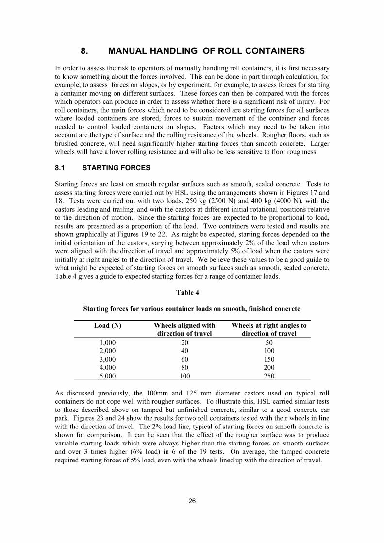
Starting forces are least on smooth regular surfaces such as smooth, sealed concrete. Tests to assess starting forces were carried out by HSL using the arrangements shown in Figures 17 and 18. Tests were carried out with two loads, 250 kg (2500 N) and 400 kg (4000 N), with the castors leading and trailing, and with the castors at different initial rotational positions relative to the direction of motion. Since the starting forces are expected to be proportional to load, results are presented as a proportion of the load. Two containers were tested and results are shown graphically at Figures 19 to 22. As might be expected, starting forces depended on the initial orientation of the castors, varying between approximately 2% of the load when castors were aligned with the direction of travel and approximately 5% of load when the castors were initially at right angles to the direction of travel. We believe these values to be a good guide to what might be expected of starting forces on smooth surfaces such as smooth, sealed concrete. Table 4 gives a guide to expected starting forces for a range of container loads.
Table 4
Starting forces for various container loads on smooth, finished concrete
Load (N) Wheels aligned with Wheels at right angles to direction of travel direction of travel
1,000 20 50 2,000 40 100 3,000 60 150 4,000 80 200 5,000 100 250
As discussed previously, the 100mm and 125 mm diameter castors used on typical roll containers do not cope well with rougher surfaces. To illustrate this, HSL carried similar tests to those described above on tamped but unfinished concrete, similar to a good concrete car park. Figures 23 and 24 show the results for two roll containers tested with their wheels in line with the direction of travel. The 2% load line, typical of starting forces on smooth concrete is shown for comparison. It can be seen that the effect of the rougher surface was to produce variable starting loads which were always higher than the starting forces on smooth surfaces and over 3 times higher (6% load) in 6 of the 19 tests. On average, the tamped concrete required starting forces of 5% load, even with the wheels lined up with the direction of travel.
26
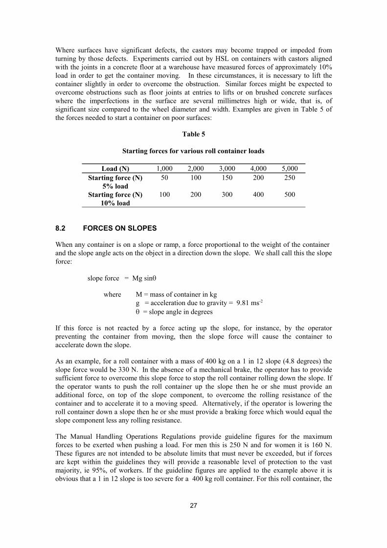
Where surfaces have significant defects, the castors may become trapped or impeded from turning by those defects. Experiments carried out by HSL on containers with castors aligned with the joints in a concrete floor at a warehouse have measured forces of approximately 10% load in order to get the container moving. In these circumstances, it is necessary to lift the container slightly in order to overcome the obstruction. Similar forces might be expected to overcome obstructions such as floor joints at entries to lifts or on brushed concrete surfaces where the imperfections in the surface are several millimetres high or wide, that is, of significant size compared to the wheel diameter and width. Examples are given in Table 5 of the forces needed to start a container on poor surfaces:
Table 5
Starting forces for various roll container loads
Load (N) 1,000 2,000 3,000 4,000 5,000 Starting force (N) 50 100 150 200 250
5% load Starting force (N) 100 200 300 400 500
10% load
8.2 FORCES ON SLOPES
When any container is on a slope or ramp, a force proportional to the weight of the container and the slope angle acts on the object in a direction down the slope. We shall call this the slope force:
slope force = Mg sinq
where M = mass of container in kg g = acceleration due to gravity = 9.81 ms-2
q = slope angle in degrees
If this force is not reacted by a force acting up the slope, for instance, by the operator preventing the container from moving, then the slope force will cause the container to accelerate down the slope.
As an example, for a roll container with a mass of 400 kg on a 1 in 12 slope (4.8 degrees) the slope force would be 330 N. In the absence of a mechanical brake, the operator has to provide sufficient force to overcome this slope force to stop the roll container rolling down the slope. If the operator wants to push the roll container up the slope then he or she must provide an additional force, on top of the slope component, to overcome the rolling resistance of the container and to accelerate it to a moving speed. Alternatively, if the operator is lowering the roll container down a slope then he or she must provide a braking force which would equal the slope component less any rolling resistance.
The Manual Handling Operations Regulations provide guideline figures for the maximum forces to be exerted when pushing a load. For men this is 250 N and for women it is 160 N. These figures are not intended to be absolute limits that must never be exceeded, but if forces are kept within the guidelines they will provide a reasonable level of protection to the vast majority, ie 95%, of workers. If the guideline figures are applied to the example above it is obvious that a 1 in 12 slope is too severe for a 400 kg roll container. For this roll container, the
27
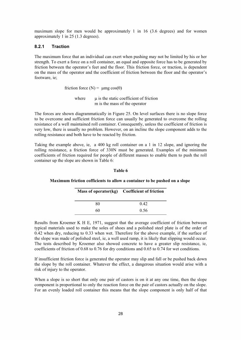
maximum slope for men would be approximately 1 in 16 (3.6 degrees) and for women approximately 1 in 25 (1.3 degrees).
8.2.1 Traction
The maximum force that an individual can exert when pushing may not be limited by his or her strength. To exert a force on a roll container, an equal and opposite force has to be generated by friction between the operator’s feet and the floor. This friction force, or traction, is dependent on the mass of the operator and the coefficient of friction between the floor and the operator’s footware, ie;
friction force (N) = mmg cos(q)
where m is the static coefficient of friction m is the mass of the operator
The forces are shown diagrammatically in Figure 25. On level surfaces there is no slope force to be overcome and sufficient friction force can usually be generated to overcome the rolling resistance of a well maintained roll container. Consequently, unless the coefficient of friction is very low, there is usually no problem. However, on an incline the slope component adds to the rolling resistance and both have to be reacted by friction.
Taking the example above, ie, a 400 kg roll container on a 1 in 12 slope, and ignoring the rolling resistance, a friction force of 330N must be generated. Examples of the minimum coefficients of friction required for people of different masses to enable them to push the roll container up the slope are shown in Table 6:
Table 6
Maximum friction cofficients to allow a container to be pushed on a slope
Mass of operator(kg) Coefficient of friction
80 0.42
60 0.56
Results from Kroemer K H E, 1971, suggest that the average coefficient of friction between typical materials used to make the soles of shoes and a polished steel plate is of the order of 0.42 when dry, reducing to 0.33 when wet. Therefore for the above example, if the surface of the slope was made of polished steel, ie, a well used ramp, it is likely that slipping would occur. The tests described by Kroemer also showed concrete to have a greater slip resistance, ie, coefficients of friction of 0.68 to 0.76 for dry conditions and 0.65 to 0.74 for wet conditions.
If insufficient friction force is generated the operator may slip and fall or be pushed back down the slope by the roll container. Whatever the effect, a dangerous situation would arise with a risk of injury to the operator.
When a slope is so short that only one pair of castors is on it at any one time, then the slope component is proportional to only the reaction force on the pair of castors actually on the slope. For an evenly loaded roll container this means that the slope component is only half of that
28
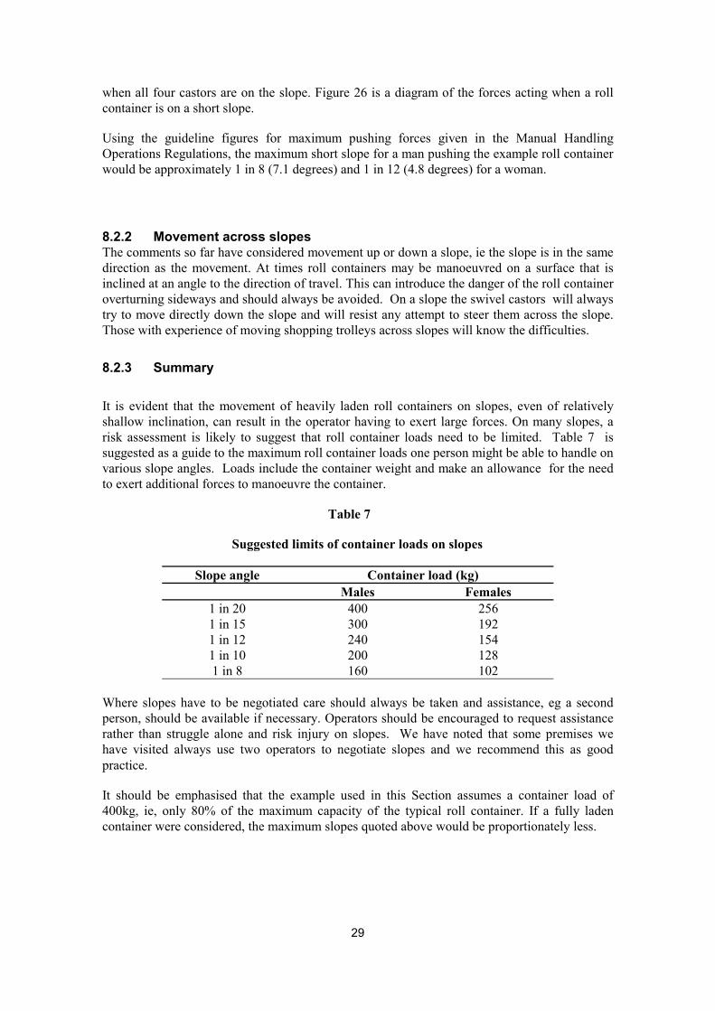
when all four castors are on the slope. Figure 26 is a diagram of the forces acting when a roll container is on a short slope.
Using the guideline figures for maximum pushing forces given in the Manual Handling Operations Regulations, the maximum short slope for a man pushing the example roll container would be approximately 1 in 8 (7.1 degrees) and 1 in 12 (4.8 degrees) for a woman.
8.2.2 Movement across slopes The comments so far have considered movement up or down a slope, ie the slope is in the same direction as the movement. At times roll containers may be manoeuvred on a surface that is inclined at an angle to the direction of travel. This can introduce the danger of the roll container overturning sideways and should always be avoided. On a slope the swivel castors will always try to move directly down the slope and will resist any attempt to steer them across the slope. Those with experience of moving shopping trolleys across slopes will know the difficulties.
8.2.3 Summary
It is evident that the movement of heavily laden roll containers on slopes, even of relatively shallow inclination, can result in the operator having to exert large forces. On many slopes, a risk assessment is likely to suggest that roll container loads need to be limited. Table 7 is suggested as a guide to the maximum roll container loads one person might be able to handle on various slope angles. Loads include the container weight and make an allowance for the need to exert additional forces to manoeuvre the container.
Table 7
Suggested limits of container loads on slopes
Slope angle Container load (kg) Males Females
1 in 20 400 256 1 in 15 300 192 1 in 12 240 154 1 in 10 200 128 1 in 8 160 102
Where slopes have to be negotiated care should always be taken and assistance, eg a second person, should be available if necessary. Operators should be encouraged to request assistance rather than struggle alone and risk injury on slopes. We have noted that some premises we have visited always use two operators to negotiate slopes and we recommend this as good practice.
It should be emphasised that the example used in this Section assumes a container load of 400kg, ie, only 80% of the maximum capacity of the typical roll container. If a fully laden container were considered, the maximum slopes quoted above would be proportionately less.
29
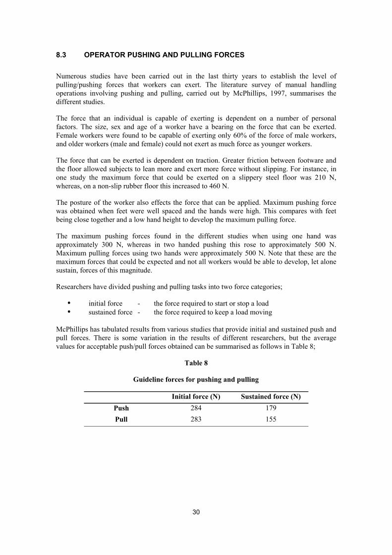
8.3 OPERATOR PUSHING AND PULLING FORCES
Numerous studies have been carried out in the last thirty years to establish the level of pulling/pushing forces that workers can exert. The literature survey of manual handling operations involving pushing and pulling, carried out by McPhillips, 1997, summarises the different studies.
The force that an individual is capable of exerting is dependent on a number of personal factors. The size, sex and age of a worker have a bearing on the force that can be exerted. Female workers were found to be capable of exerting only 60% of the force of male workers, and older workers (male and female) could not exert as much force as younger workers.
The force that can be exerted is dependent on traction. Greater friction between footware and the floor allowed subjects to lean more and exert more force without slipping. For instance, in one study the maximum force that could be exerted on a slippery steel floor was 210 N, whereas, on a non-slip rubber floor this increased to 460 N.
The posture of the worker also effects the force that can be applied. Maximum pushing force was obtained when feet were well spaced and the hands were high. This compares with feet being close together and a low hand height to develop the maximum pulling force.
The maximum pushing forces found in the different studies when using one hand was approximately 300 N, whereas in two handed pushing this rose to approximately 500 N. Maximum pulling forces using two hands were approximately 500 N. Note that these are the maximum forces that could be expected and not all workers would be able to develop, let alone sustain, forces of this magnitude.
Researchers have divided pushing and pulling tasks into two force categories;
� initial force - the force required to start or stop a load � sustained force - the force required to keep a load moving
McPhillips has tabulated results from various studies that provide initial and sustained push and pull forces. There is some variation in the results of different researchers, but the average values for acceptable push/pull forces obtained can be summarised as follows in Table 8;
Table 8
Guideline forces for pushing and pulling
Initial force (N) Sustained force (N) Push 284 179 Pull 283 155
30
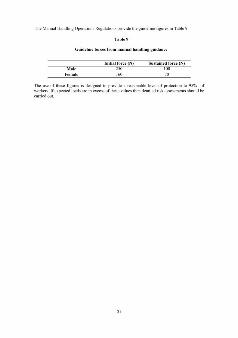
The Manual Handling Operations Regulations provide the guideline figures in Table 9;
Table 9
Guideline forces from manual handling guidance
Initial force (N) Sustained force (N) Male 250 100
Female 160 70
The use of these figures is designed to provide a reasonable level of protection to 95% of workers. If expected loads are in excess of these values then detailed risk assessments should be carried out.
31
9. MECHANICAL HANDLING OF ROLL CONTAINERS
Warehouses and distribution depots are often purpose designed and organised to minimise the manual handling of roll containers by the use of fork lift trucks which can lift the containers, usually from the side, in multiples of two or three, see Figure 27. The truck, once loaded with empty containers can then be driven along the aisles to collect the goods destined for a particular store. Loading docks generally allow road vehicles to be parked essentially level with the warehouse floor, with any difference taken up by the use of dock levellers. This allows laden containers to be driven into the vehicles with the minimum of manual handling. Vehicles will also be parked on level ground and the risk of unrestrained containers running away is very low.
The main disadvantage of this system is that a lower standard of container maintenance can be tolerated by the warehouse because the need for manual handling is low. The warehouse is also the place where empty cages are inspected prior to being loaded with goods. It is important that this inspection takes account of the need for manual handling down the line rather than just the needs of the warehouse.
Equipment is available which allows individual containers to be mechanically handled at the store. We have no detailed information on the efficacy of this equipment but trials are known to be ongoing. The common reaction we have had to the use of such equipment is that it is too costly to have more than one piece of equipment per store and that it is of limited use in congested areas. As a result, the manual handling of roll containers at retail premises is likely to continue for some time.
32
10. CONCLUSIONS
1. Roll containers are a convenient way of distributing goods and have both helped to speed up the distribution and reduce the need for manual handling of goods. A typical fully-loaded container can weigh up to 500 kg and, although the container is often mechanically handled at the point of dispatch, it must itself be manually handled at its destination. The destination could be a modern superstore, with smooth and level floors throughout, or a high street shop, where the handling of the container may involve movement on slopes, across changes in floor level or floor surface. At most destinations, there will be congested back of store/shop areas where manoeuvering of a 500 kg load on 125 mm castors is not easy. We believe that it is important, at the point of loading, to consider risks which the container might pose throughout its journey and at all destinations where it will be manually handled. Where there are too wide a variety of destinations to consider individually, grouping of similar destinations or a presumption of the worst case would be best practice.
2. Comprehensive statistics on roll container accidents are not available but we have collected sufficient information to illustrate that they are involved in a large number of accidents. These represent:
� 3% of reported RIDDOR reportable accidents in Sheffield
� 30% of manual handling accidents to sales assistants referred to the Royal Liverpool University Hospital
� 35% of reported accidents in one sector of a major distribution company
� 20% of reported accidents in a major supermarket chain.
3. The most important design features which would help reduce roll container accidents are:
� larger diameter wheels, to reduce pushing/pulling forces and to make these less sensitive to imperfections in the surfaces on which containers are used
� the incorporation of handles, to move fingers and hands away from the corners of containers where they are vulnerable to impact and trapping damage and, when cages are pulled, to move feet further away from the container and reduce the risk of foot injuries
� marked load height limits, to enable the operator to have a clear view when containers are pushed.
� castors close to corners to improve stability
4. When roll containers are used on flat, level surfaces, the maximum forces to move and manoeuvre containers will typically be 2 % of the load with the wheels aligned with the direction of travel and 5% of load with the wheels at right angles to the direction of travel. In the worst case, with the heaviest load of 500 kg, starting forces of around 250 N can be expected. These forces are just within the the maximum we would expect male operators to be asked to handle without a risk assessment but above the force of 160 N we would expect female operators to be asked to handle without a risk assessment. With uneven surfaces, the maximum starting force could be expected to rise to 10 % of the load. It is clear that the
33
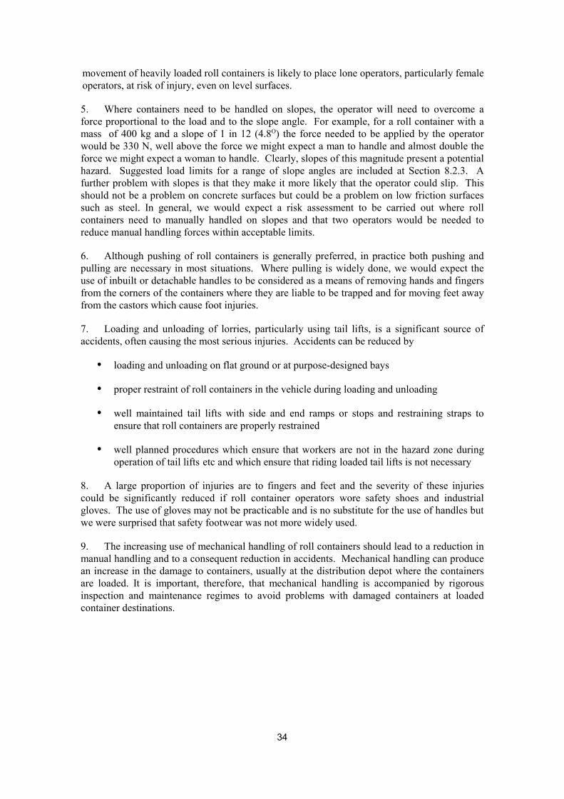
movement of heavily loaded roll containers is likely to place lone operators, particularly female operators, at risk of injury, even on level surfaces.
5. Where containers need to be handled on slopes, the operator will need to overcome a force proportional to the load and to the slope angle. For example, for a roll container with a mass of 400 kg and a slope of 1 in 12 (4.8O) the force needed to be applied by the operator would be 330 N, well above the force we might expect a man to handle and almost double the force we might expect a woman to handle. Clearly, slopes of this magnitude present a potential hazard. Suggested load limits for a range of slope angles are included at Section 8.2.3. A further problem with slopes is that they make it more likely that the operator could slip. This should not be a problem on concrete surfaces but could be a problem on low friction surfaces such as steel. In general, we would expect a risk assessment to be carried out where roll containers need to manually handled on slopes and that two operators would be needed to reduce manual handling forces within acceptable limits.
6. Although pushing of roll containers is generally preferred, in practice both pushing and pulling are necessary in most situations. Where pulling is widely done, we would expect the use of inbuilt or detachable handles to be considered as a means of removing hands and fingers from the corners of the containers where they are liable to be trapped and for moving feet away from the castors which cause foot injuries.
7. Loading and unloading of lorries, particularly using tail lifts, is a significant source of accidents, often causing the most serious injuries. Accidents can be reduced by
� loading and unloading on flat ground or at purpose-designed bays
� proper restraint of roll containers in the vehicle during loading and unloading
� well maintained tail lifts with side and end ramps or stops and restraining straps to ensure that roll containers are properly restrained
� well planned procedures which ensure that workers are not in the hazard zone during operation of tail lifts etc and which ensure that riding loaded tail lifts is not necessary
8. A large proportion of injuries are to fingers and feet and the severity of these injuries could be significantly reduced if roll container operators wore safety shoes and industrial gloves. The use of gloves may not be practicable and is no substitute for the use of handles but we were surprised that safety footwear was not more widely used.
9. The increasing use of mechanical handling of roll containers should lead to a reduction in manual handling and to a consequent reduction in accidents. Mechanical handling can produce an increase in the damage to containers, usually at the distribution depot where the containers are loaded. It is important, therefore, that mechanical handling is accompanied by rigorous inspection and maintenance regimes to avoid problems with damaged containers at loaded container destinations.
34
REFERENCES
McPhillips L, 1997, Manual Handling Operations involving Pushing and Pulling, Health andSafety Executive, Health Directorate.
Manual Handling, Guidance on Manual Handling Operations Regulations 1992, Guidance onRegulations, Health and Safety Executive, 1998, ISBN 0717625153.
Manual handling injuries to workers attending the Royal Liverpool University Hospital, Healthand Safety Executive, Contract Research Report 213/1999.
Manual Handling Operations Regulations, 1992.
Lifting Operations and Lifting Equipment Regulations, 1998.
Provision and Use of work Equipment Regulations, 1998.
Supply of Machinery (Safety) Regulations, 1992 (as amended)
Kroemer K H E, 1971, Horizontal static forces exerted by men standing in common workingpositions on surfaces of various tractions, Aerospace Medical Research Laboratory.
35
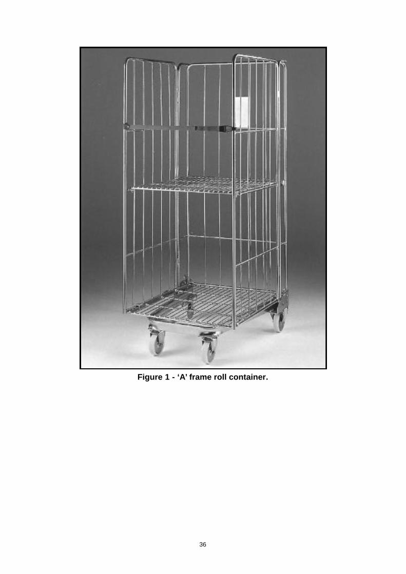
Figure 1 - ‘A’ frame roll container.
36
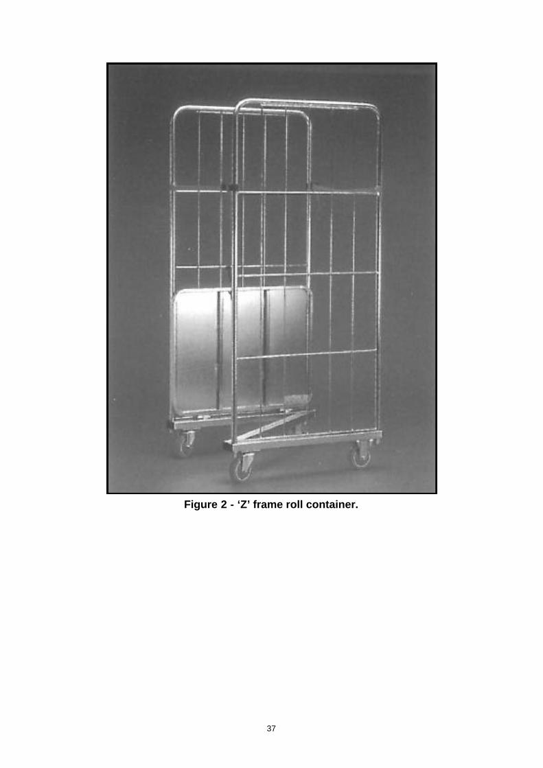
Figure 2 - ‘Z’ frame roll container.
37
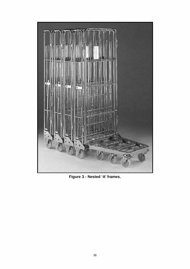
Figure 3 - Nested ‘A’ frames.
38
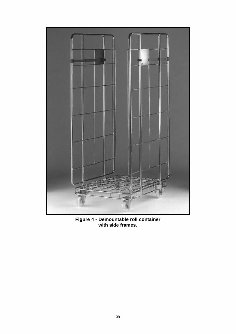
Figure 4 - Demountable roll container with side frames.
39
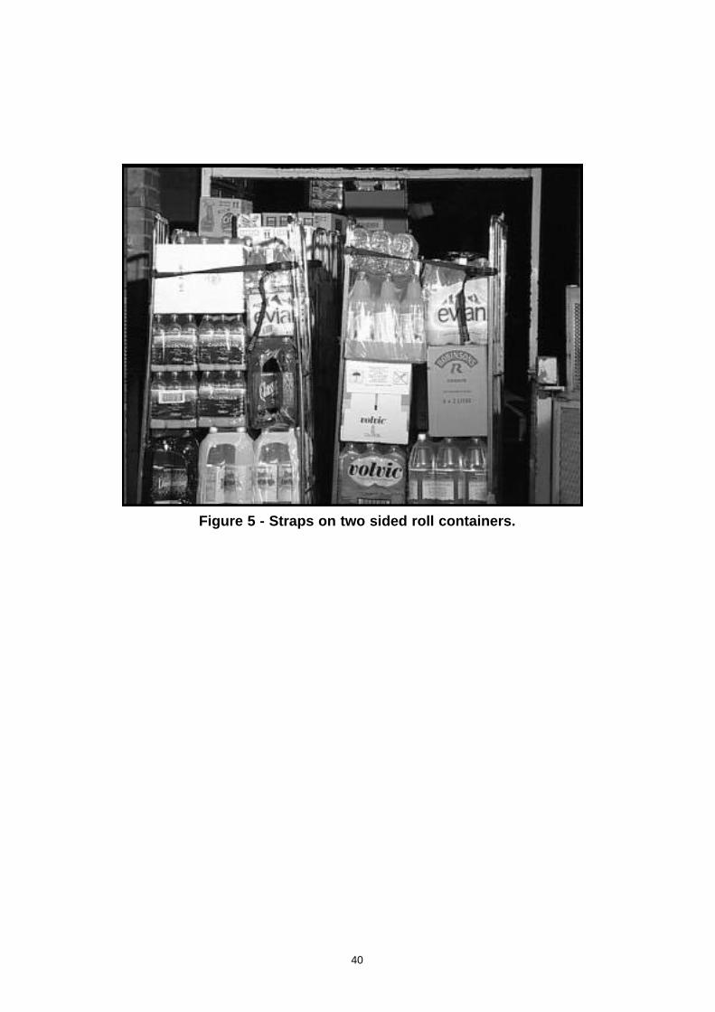
Figure 5 - Straps on two sided roll containers.
40
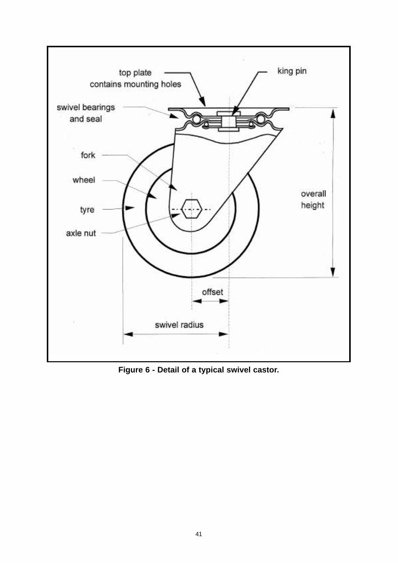
Figure 6 - Detail of a typical swivel castor.
41
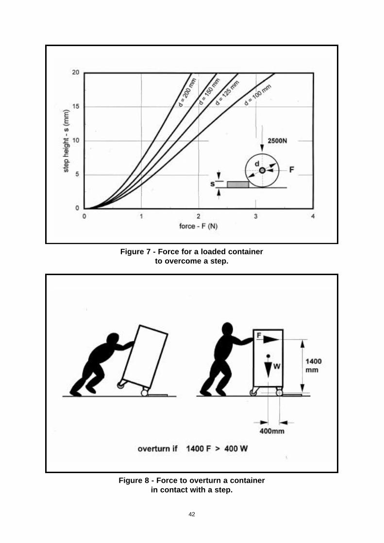
Figure 7 - Force for a loaded containerto overcome a step.
Figure 8 - Force to overturn a containerin contact with a step.
42
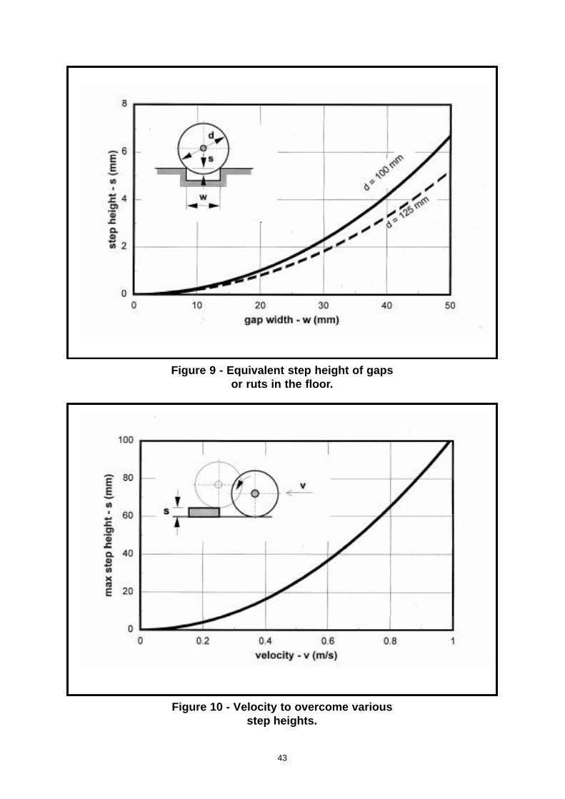
Figure 9 - Equivalent step height of gapsor ruts in the floor.
Figure 10 - Velocity to overcome variousstep heights.
43
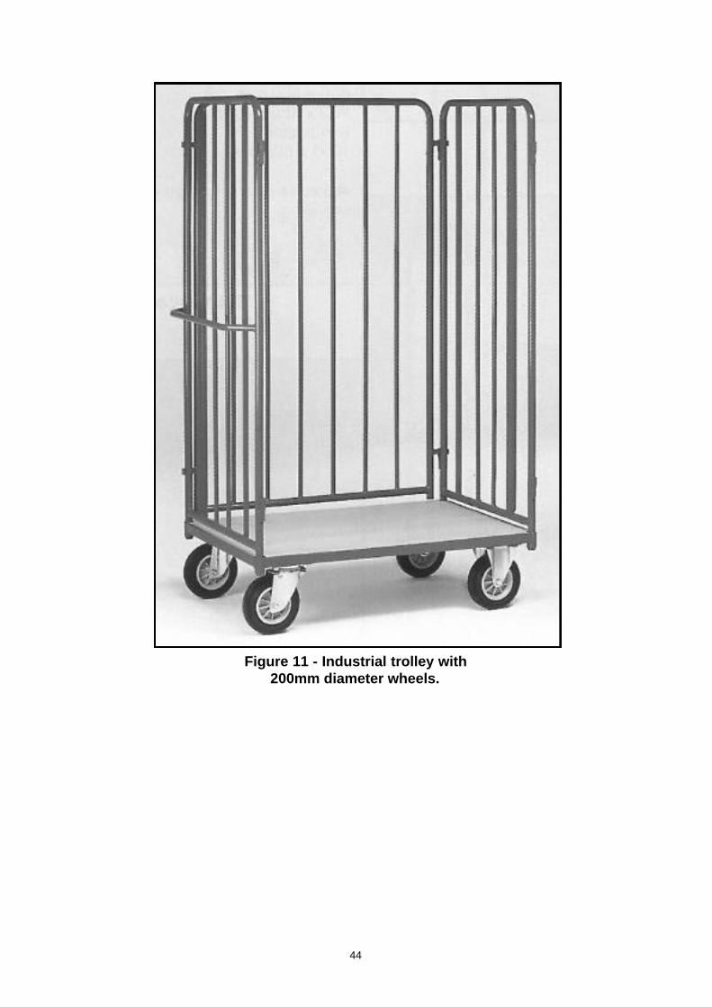
Figure 11 - Industrial trolley with 200mm diameter wheels.
44
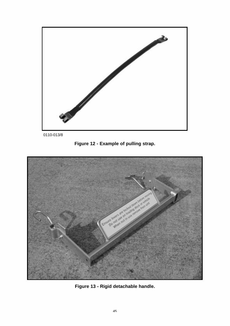
0110-013/8
Figure 12 - Example of pulling strap.
Figure 13 - Rigid detachable handle.
45
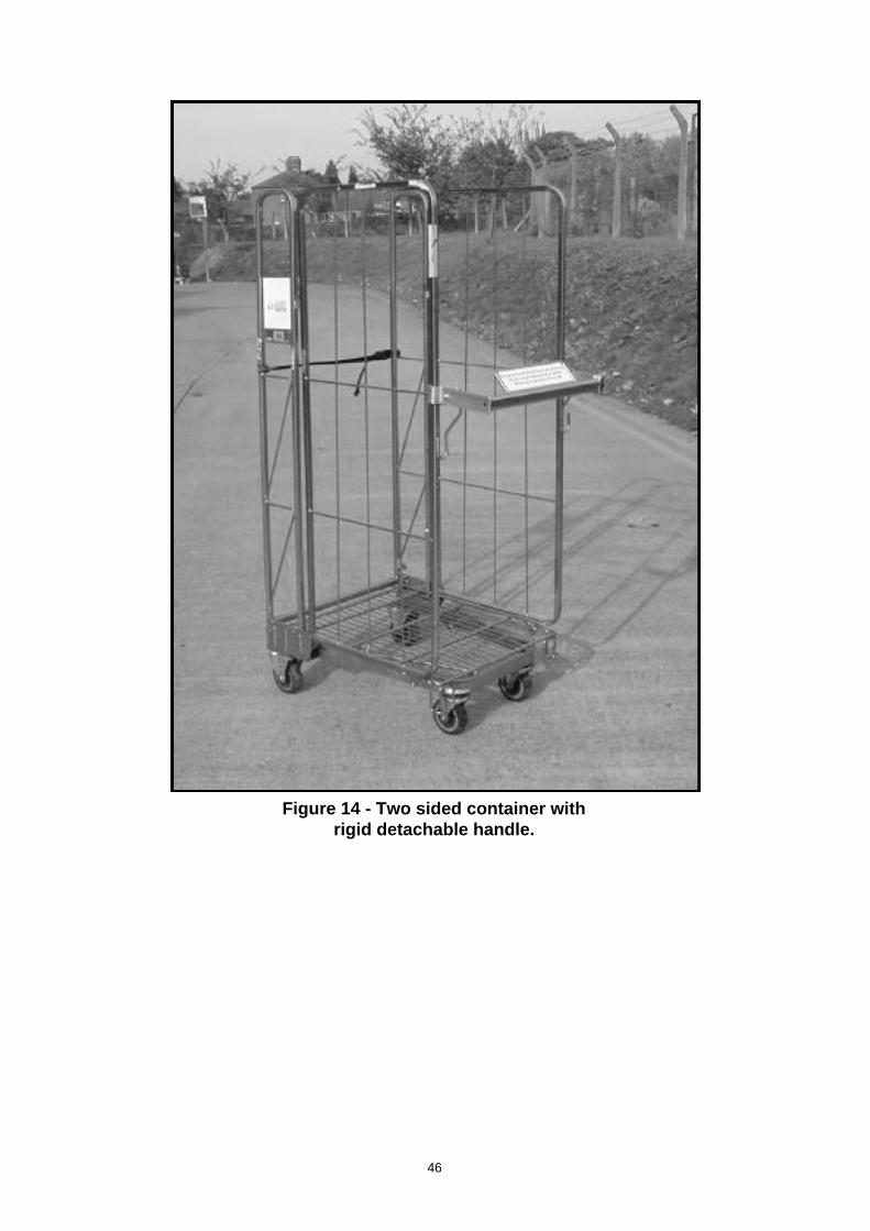
Figure 14 - Two sided container with rigid detachable handle.
46
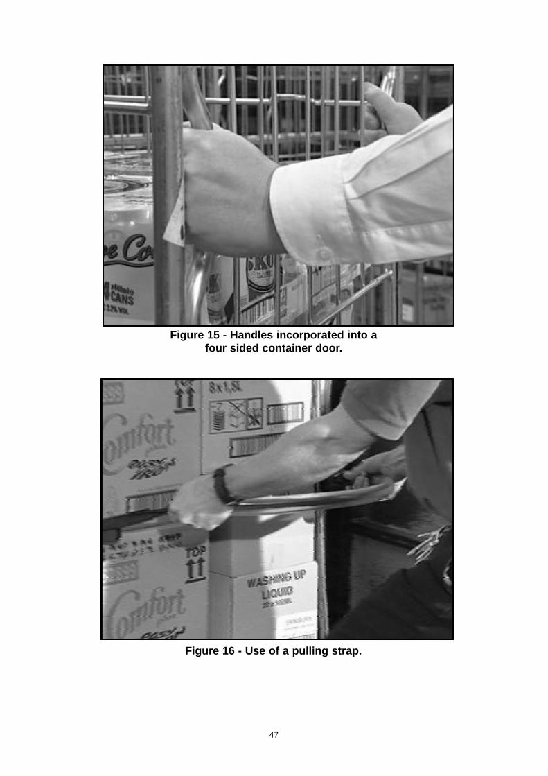
Figure 15 - Handles incorporated into afour sided container door.
Figure 16 - Use of a pulling strap.
47
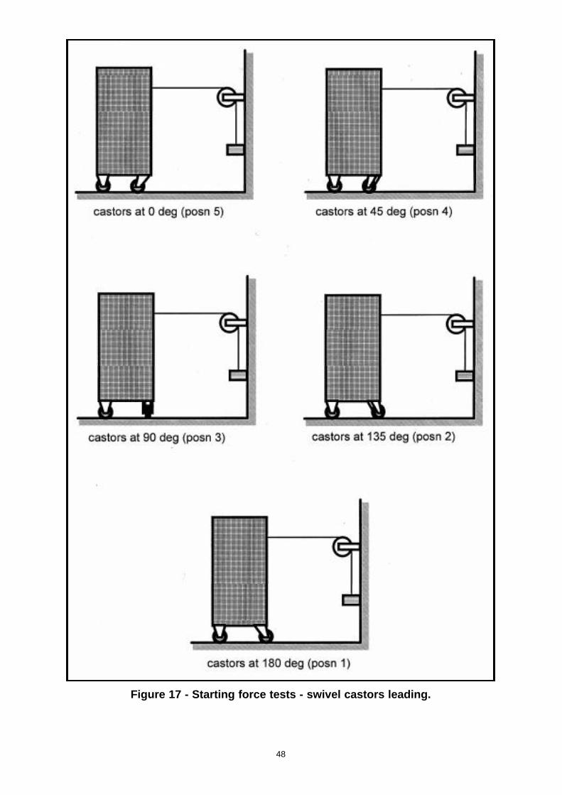
Figure 17 - Starting force tests - swivel castors leading.
48
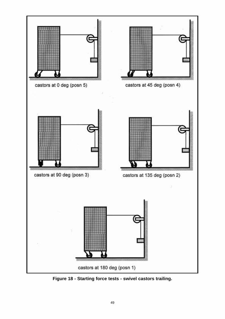
Figure 18 - Starting force tests - swivel castors trailing.
49
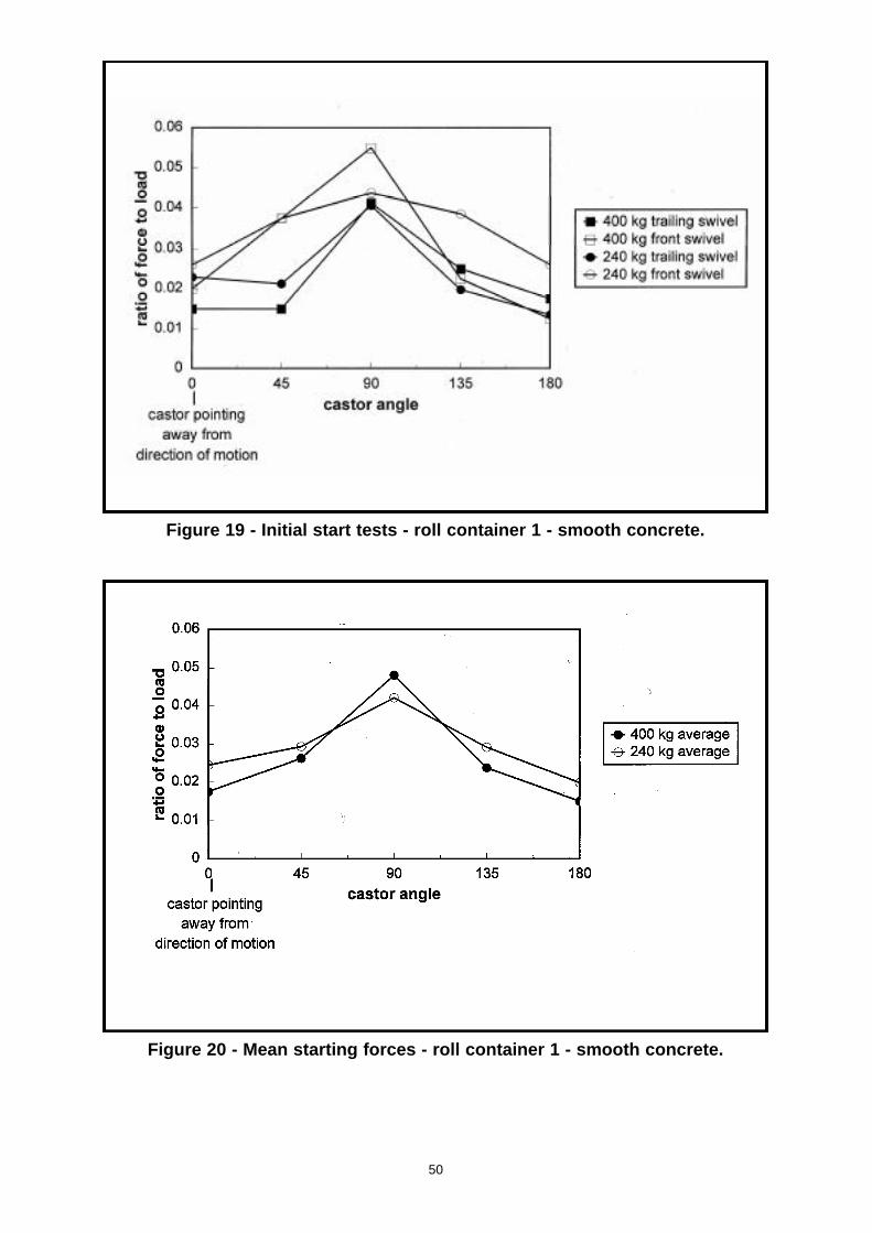
Figure 19 - Initial start tests - roll container 1 - smooth concrete.
Figure 20 - Mean starting forces - roll container 1 - smooth concrete.
50
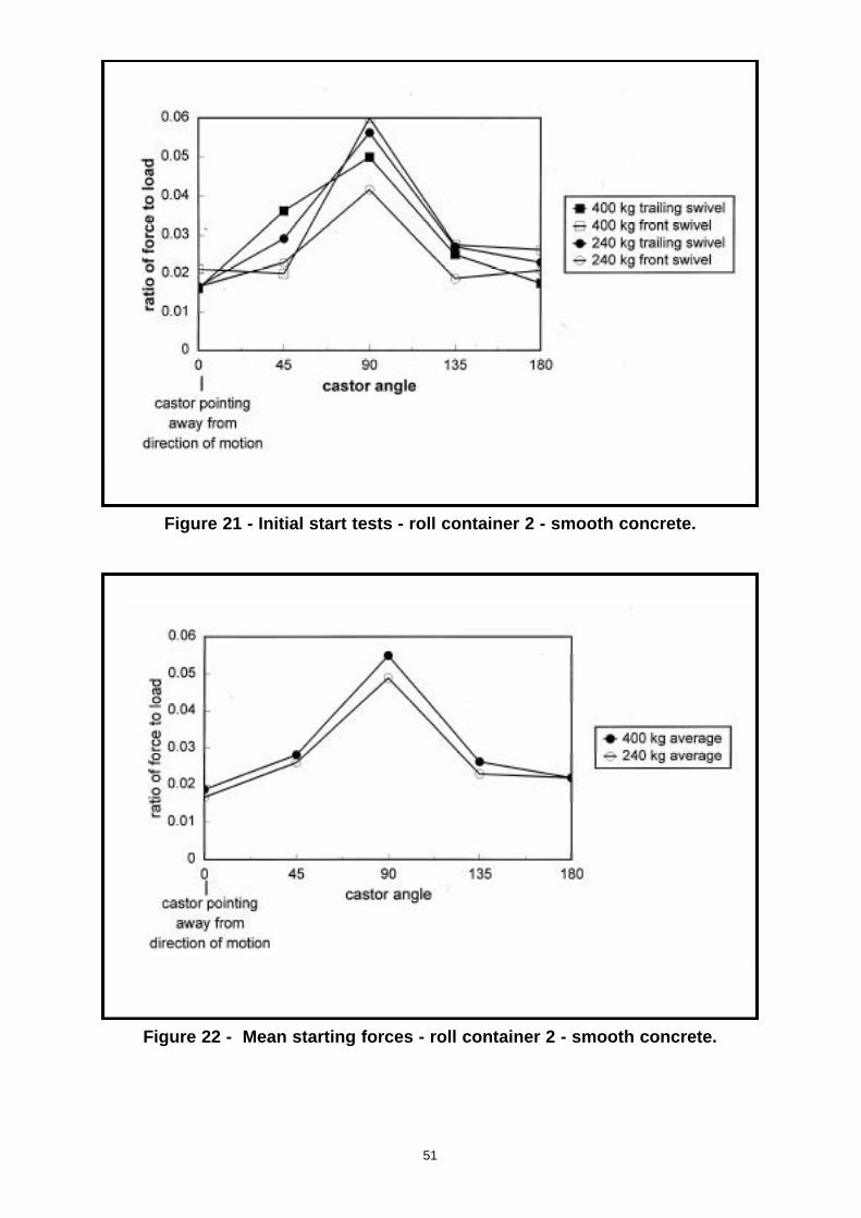
Figure 21 - Initial start tests - roll container 2 - smooth concrete.
Figure 22 - Mean starting forces - roll container 2 - smooth concrete.
51
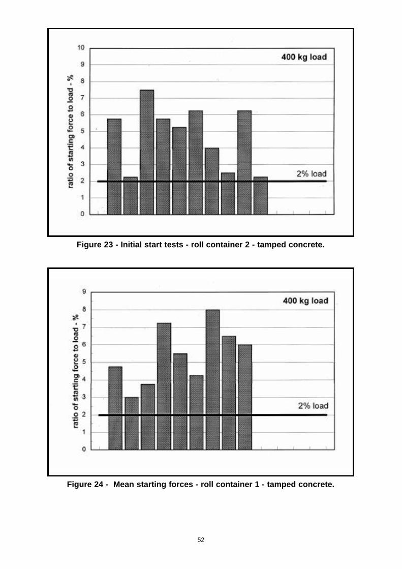
Figure 23 - Initial start tests - roll container 2 - tamped concrete.
Figure 24 - Mean starting forces - roll container 1 - tamped concrete.
52
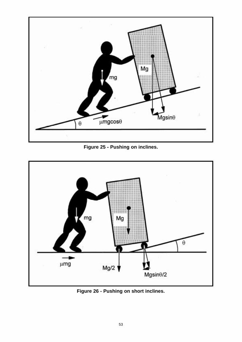
Figure 25 - Pushing on inclines.
Figure 26 - Pushing on short inclines.
53
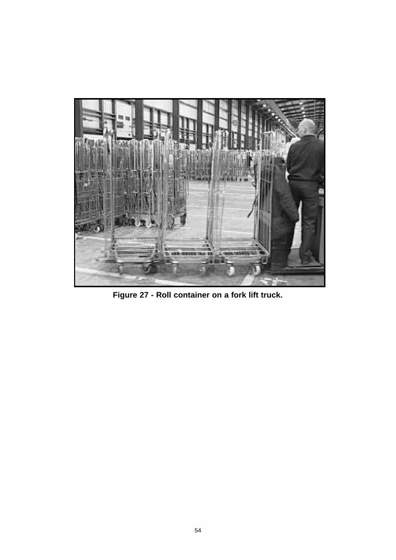
Figure 27 - Roll container on a fork lift truck.
54
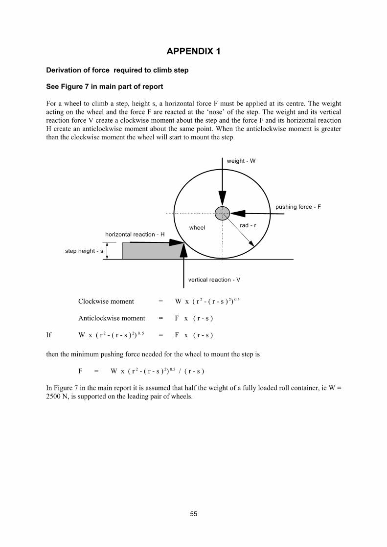
APPENDIX 1
Derivation of force required to climb step
See Figure 7 in main part of report
For a wheel to climb a step, height s, a horizontal force F must be applied at its centre. The weight acting on the wheel and the force F are reacted at the ‘nose’ of the step. The weight and its vertical reaction force V create a clockwise moment about the step and the force F and its horizontal reaction H create an anticlockwise moment about the same point. When the anticlockwise moment is greater than the clockwise moment the wheel will start to mount the step.
l i
wei
vertica react on - V
pushing force - F
ght - W
step height - s
horizontal reaction - H rad - r wheel
Clockwise moment = W x ( r 2 - ( r - s ) 2) 0.5
Anticlockwise moment = F x ( r - s )
If W x ( r 2 - ( r - s ) 2) 0. 5 = F x ( r - s )
then the minimum pushing force needed for the wheel to mount the step is
F = W x ( r 2 - ( r - s ) 2) 0.5 / ( r - s )
In Figure 7 in the main report it is assumed that half the weight of a fully loaded roll container, ie W = 2500 N, is supported on the leading pair of wheels.
55
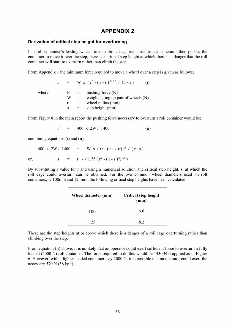
APPENDIX 2
Derivation of critical step height for overturning
If a roll container’s leading wheels are positioned against a step and an operator then pushes the container to move it over the step, there is a critical step height at which there is a danger that the roll container will start to overturn rather than climb the step.
From Appendix 1 the minimum force required to move a wheel over a step is given as follows;
F = W x ( r 2 - ( r - s ) 2) 0.5 / ( r - s ) (i)
where F = pushing force (N) W = weight acting on pair of wheels (N) r = wheel radius (mm) s = step height (mm)
From Figure 8 in the main report the pushing force necessary to overturn a roll container would be;
F = 400 x 2W / 1400 (ii)
combining equations (i) and (ii),
400 x 2W / 1400 = W x ( r 2 - ( r - s ) 2) 0.5 / ( r - s )
0.5 )or, s = r - ( 1.75 ( r 2 - ( r - s ) 2)
By substituting a value for r and using a numerical solution, the critical step height, s, at which the roll cage could overturn can be obtained. For the two common wheel diameters used on roll containers, ie 100mm and 125mm, the following critical step heights have been calculated:
Wheel diameter (mm) Critical step height (mm)
100 6.6
125 8.2
These are the step heights at or above which there is a danger of a roll cage overturning rather than climbing over the step.
From equation (ii) above, it is unlikely that an operator could exert sufficient force to overturn a fully loaded (5000 N) roll container. The force required to do this would be 1430 N if applied as in Figure 6. However, with a lighter loaded container, say 2000 N, it is possible that an operator could exert the necessary 570 N (58 kg f).
56
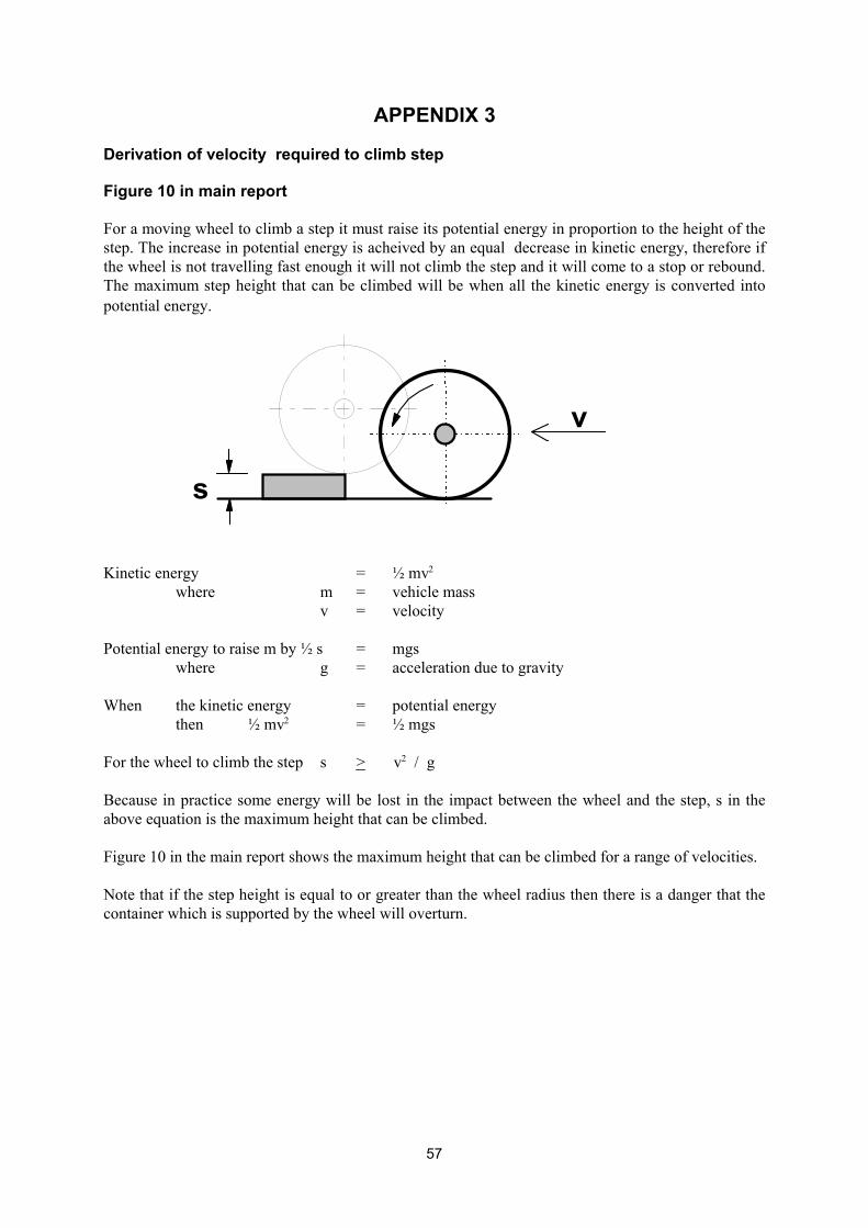
APPENDIX 3
Derivation of velocity required to climb step
Figure 10 in main report
For a moving wheel to climb a step it must raise its potential energy in proportion to the height of the step. The increase in potential energy is acheived by an equal decrease in kinetic energy, therefore if the wheel is not travelling fast enough it will not climb the step and it will come to a stop or rebound. The maximum step height that can be climbed will be when all the kinetic energy is converted into potential energy.
s
v
Kinetic energy = ½ mv2
where m = vehicle mass v = velocity
Potential energy to raise m by ½ s = mgs where g = acceleration due to gravity
When the kinetic energy = potential energy then ½ mv2 = ½ mgs
For the wheel to climb the step s > v2 / g
Because in practice some energy will be lost in the impact between the wheel and the step, s in the above equation is the maximum height that can be climbed.
Figure 10 in the main report shows the maximum height that can be climbed for a range of velocities.
Note that if the step height is equal to or greater than the wheel radius then there is a danger that the container which is supported by the wheel will overturn.
57
APPENDIX 4
List of contributors of information on roll container use
Asda Bekaert Handling & Display Limited Fallshaw Wheels & Castors Palletlink Palmer & Harvey Mc Lane Limited Royal Mail Sainsbury’s Supermarkets Limited The Logistics Safety Forum TNT Express (UK) Limited Waitrose Tesco Somerfield USDAW
List of contributors of information on roll containers Buko Proto-Tech CargoPak Unicontainer Bekaert Handling and Display Ltd Clares Merchandise Handling Equipment Ltd Variant Systemet Storagewise Materials Handling Equipment Radford Retail Systems
List of contributors of information on mechanical aids
Stokvis Unidok Materials Handling Equipment SP Hydraulic Dock Levellers MasterMover International Ltd
58
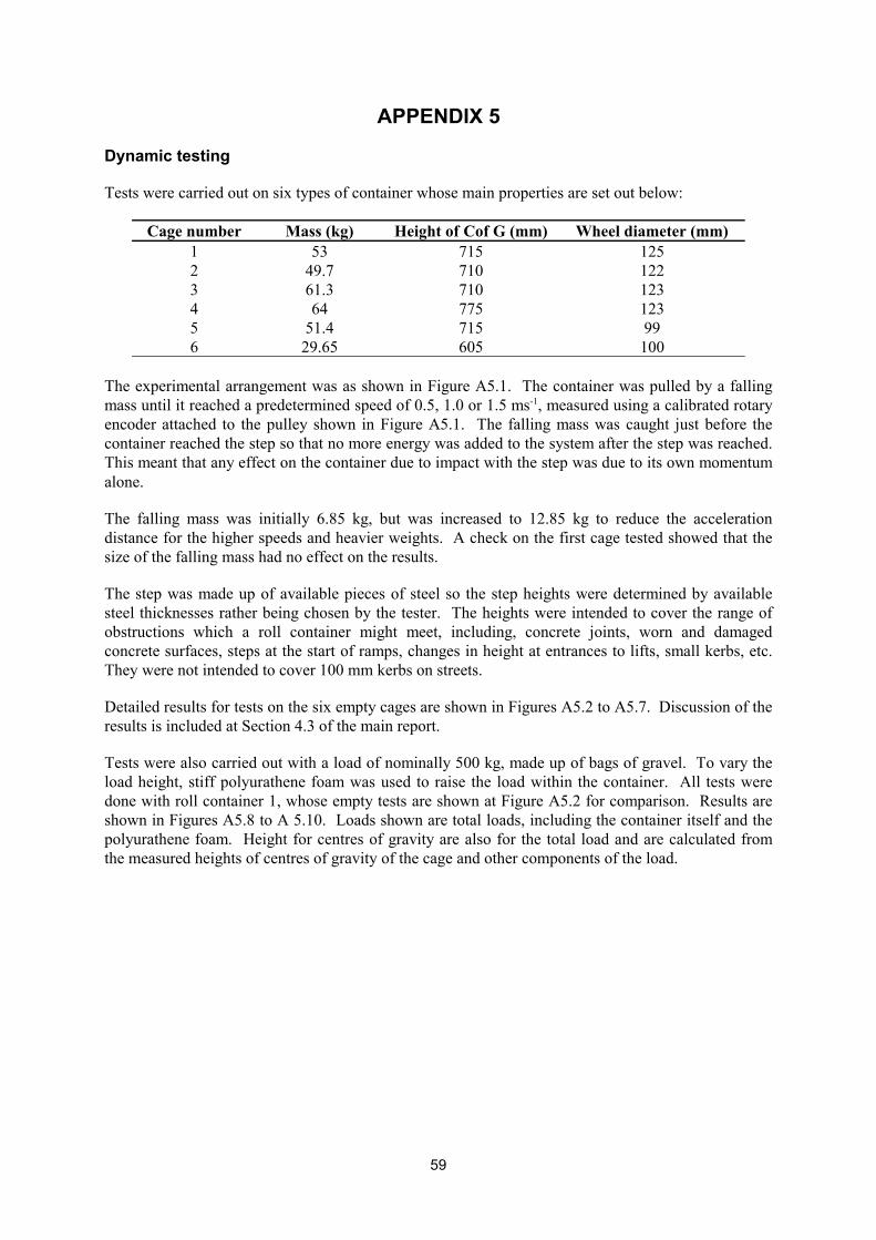
APPENDIX 5
Dynamic testing
Tests were carried out on six types of container whose main properties are set out below:
Cage number Mass (kg) Height of Cof G (mm) Wheel diameter (mm) 1 53 715 125 2 49.7 710 122 3 61.3 710 123 4 64 775 123 5 51.4 715 99 6 29.65 605 100
The experimental arrangement was as shown in Figure A5.1. The container was pulled by a falling mass until it reached a predetermined speed of 0.5, 1.0 or 1.5 ms-1, measured using a calibrated rotary encoder attached to the pulley shown in Figure A5.1. The falling mass was caught just before the container reached the step so that no more energy was added to the system after the step was reached. This meant that any effect on the container due to impact with the step was due to its own momentum alone.
The falling mass was initially 6.85 kg, but was increased to 12.85 kg to reduce the acceleration distance for the higher speeds and heavier weights. A check on the first cage tested showed that the size of the falling mass had no effect on the results.
The step was made up of available pieces of steel so the step heights were determined by available steel thicknesses rather being chosen by the tester. The heights were intended to cover the range of obstructions which a roll container might meet, including, concrete joints, worn and damaged concrete surfaces, steps at the start of ramps, changes in height at entrances to lifts, small kerbs, etc. They were not intended to cover 100 mm kerbs on streets.
Detailed results for tests on the six empty cages are shown in Figures A5.2 to A5.7. Discussion of the results is included at Section 4.3 of the main report.
Tests were also carried out with a load of nominally 500 kg, made up of bags of gravel. To vary the load height, stiff polyurathene foam was used to raise the load within the container. All tests were done with roll container 1, whose empty tests are shown at Figure A5.2 for comparison. Results are shown in Figures A5.8 to A 5.10. Loads shown are total loads, including the container itself and the polyurathene foam. Height for centres of gravity are also for the total load and are calculated from the measured heights of centres of gravity of the cage and other components of the load.
59

Printed and published by the Health and Safety ExecutiveC30 1/98
Printed and published by the Health and Safety ExecutiveC1.25 11/02
ISBN 0-7176-2535-4
RR 009
780717625352£15.00 9