Embed Size (px)
Citation preview
Research Report
University of Wisconsin-MadisonCollege of Engineering
Wisconsin Power Electronics Research Center2559D Engineering Hall1415 Engineering DriveMadison WI 53706-1691
© Confidential
2014-39
Dynamics and Vector Control of Wound-RotorBrushless Doubly Fed Induction Machines
Z. S. Du, T. A. Lipo
Dept. of Elect. & Comp. Engr.University of Wisconsin-Madison
1415 Engineering DriveMadison, WI 53706

Dynamics and Vector Control of Wound-RotorBrushless Doubly Fed Induction Machines
Zhentao S. DuDept. of Electrical and Computer Engineering
University of Wisconsin-MadisonMadison, WI 53706 USA
Email: [email protected]
Thomas A. LipoDept. of Electrical and Computer Engineering
University of Wisconsin-MadisonMadison, WI 53706 USAEmail: [email protected]
Abstract—This paper proposes a Wound-Rotor Brushless Dou-bly Fed Induction Machine (WRBDFIM), an alternative Brush-less Doubly Fed Induction Machine (BDFIM) concept for windturbine applications. The WRBDFIM consists of two separatemachine winding sets different in pole-numbers, whose rotorwindings are connected together. Both of the winding sets arehoused in the same machine frame. The separate winding setarrangement aims to eliminate the circulating current and sup-press the undesired spatial harmonics created by the conventionalBDFIM. The two-phase equivalent circuit of the WRBDFIM isderived by connecting the circuits of two conventional DoublyFed Induction Machines (DFIMs). The electrical and mechanicaldynamics are identified to form the machine model for theDirect Power Vector Control (DPVC), which is proposed toregulate the generated power of the WRBDFIM without rotorposition sensors. Simulation results confirm the machine dynamicmodel and also prove the effectiveness of the DPVC scheme thatprovides accurate control and fast tracking capability.
I. INTRODUCTION
Wind power generation, a key renewable energy technology,converts natural wind power to electrical power in a clean, ef-ficient, and cost-effective manner through the usage of a windturbine and an electrical generator. The Doubly Fed InductionGenerator (DFIG) is one of the current main players in windpower generation due to their lower size drive requirement(approximately 30% of the rated power [1]) comparing to thatof other machines; and the slip power recovery, which servesto further improve efficiency. [2] The main drawback of DFIGsis the presence of the brushes and slip rings used to enableaccess to the rotor terminals. Due to the direct contact betweenthe rotor and the brushes, the brushes are worn out withina regular period of time. Besides the construction cost, themaintenance cost significantly increases the overall cost of awind-turbine unit from a long term perspective.
The design of conventional Brushless Doubly Fed Induc-tion Machines (BDFIMs) is based on the cascaded inductionmachine principle devised by Hunt [3], which uses a singleset of stator windings to produce two spatial MagnetomotiveForces (MMFs), different in pole-numbers, rotating in the airgap, which interact with a nested-loop rotor. [4]–[8] While thisdesign eliminates the costly usage of brushes and slip rings, themain drawbacks of the conventional BDFIMs design are thechoice of the single stator winding set and the complex design
of the nested-loop rotor. The single stator winding set createsan unbalanced mutual inductance, resulting in a circulatingcurrent flowing through the phase windings, which leads tohigher copper loss. [9] The nested-loop rotor has been provento create other unwanted spatial harmonics [10] that impairthe performance of the machine.
Brushless Doubly Fed Reluctance Machines (BDFRMs),the counterparts of BDFIMs, are claimed to offer higherefficiency since their salient rotors do not require copperconductors. [11]–[13] In addition, BDFRMs could potentiallyease the rotor manufacture. Thus far, a quantitative comparisonof features between the BDFIM and BDFRM has no yetappeared. However, in the case of normal singly fed machines,use of reluctance machines is rare and induction machineshave retained their favor over reluctance machines becauseof their better power factor/efficency product and overloadcapability among others. It is not unseemly to expect thesesame advantages may also pertain to doubly fed configurationsas well. In any case the issue of the pros and cons of thesetwo solutions are an interesting subject of future research butnot the issue of this paper.
This paper proposes a different type of BDFIM, namelythe Wound-Rotor Brushless Doubly Fed Induction Machine(WRBDFIM), which is essentially a connection of two DoublyFed Induction Machines (DFIMs) with different pole-pairnumber housed in the same frame. The fundamental mutualinductance between the two winding sets is zero and thehigher harmonic mutual inductances are so small that they areneglected in this paper. In fact, the existence of these harmonicmutual couplings creates small amount of undesired torqueripple; however the torque ripple is significantly reducedcompared to that of conventional BDFIMs using a nested-loop rotor due to the choice of the separate rotor winding setsin the WRBDFIM. Furthermore, the stator of the WRBDFIMhas two separate stator winding sets purposely to eliminate thecirculating current [9] in the stator windings of conventionalBDFIMs where the two stator currents share the commonstator winding set to create two distinctive pole-pair magneticfields.
The configuration of the WRBDFIM is shown in Fig. 1.The stator winding set that connects directly to the grid iscalled the Main Machine Winding Set (MMWS); the other
978-1-4799-5776-7/14/$31.00 c©2014 IEEE

Bi-Directional
Power Drive SystemWRBDFIM
Grid BusbarsThree-phase
Fig. 1. The configuration of the WRBDFIM with an AC drive.
stator winding set that connects to the inverter is called theControl Machine Winding Set (CMWS). The MMWS and theCMWS are shorted with each other on the rotor. At the pointof connection between the two rotor windings, the A-phase,B-phase, and C-phase of the MMWS are connected to the A-phase, C-phase, and B-phase of the CMWS, respectively. Thepurpose of the reverse phase sequence is mainly to reverse thedirection of the rotating MMF of the rotor of the CMWS.
The structure of the machine is the same as that of theconventional wound-rotor induction machine with two-layerwindings. The slots accommodate the two sets of windings inboth the stator and rotor, as shown in Fig. 2. The machineis easier to manufacture compared to that of the counterpartBDFRM. The two-phase equivalent circuit of the WRBDFIMis readily derived, followed by the modelling of the machinedynamics. In addition, this paper proposes a new vector controldesign for the proposed WRBDFIMs based on the work [14]for DFIMs, which features an accurate, robust, and feasibleDPVC scheme without rotor position sensors that are essentialin the control schemes proposed by [8], [15], [16].
II. OPERATING PRINCIPLE
The WRBDFIM produces average torque only if the fre-quency of the excitation applied to the stator terminals ofthe CMWS is in synchronization with the frequency thatis induced in the stator CMWS. Such a rotating frequencycan be obtained using a speed vector diagram, as shownin Fig. 3, which summarizes all the frequencies of the fluxwaves rotating in the air gap. Let the rotor be rotating at themechanical angular frequency ωrm, the frequency of the fluxwave induced due to the rotor MMWS is equal to the mainmachine slip frequency, as shown in (1).
ωsl = ωe1 − P1ωrm (1)
Since the phase sequence is reversed at the point of rotorconnection, the flux wave due to the rotor CMWS is oppositeto the main machine slip frequency, i.e. −ωsl1. Since the rotoritself is rotating at ωrm, the resultant speed vector in referenceto the stator frame of the CMWS is equal to the frequencyinduced in the stator CMWS, i.e.
ωe2 = −ωsl1 + P2ωrm (2)
It should be noted that both rotor winding sets share thesame mechanical rotor frequency; however, their electricalrotor frequencies are different due to their difference in pole
Stator
Rotor
Air-gap
MMWS
( P1 pole pairs)
CMWS
(P2 pole pairs)
Fig. 2. The stator and rotor winding scheme of the WRBDFIM. Note: P1
and P2 are the number of pole pairs of the MMWS and CMWS respectively.Henceforth, ‘1’ and ‘2’ denote a MMWS and CMWS quantity, respectively.
Rotor of MMWS
(P1 pole pairs)
Rotor of CMWS
(P2 pole pairs)
ωe1 P1ωrm ωsl1
ωe2
ωsl1 P2ωrm
Fig. 3. The speed vector diagram summarizes all the flux waves rotatingin the air-gap. Note: ωe1, ωrm, ωsl1, ωe2 denote the main machine grid-excitation frequency, the rotor mechanical frequency, the main machine slipfrequency, and the control machine induction frequency, respectively.
numbers. The slip of each machine can be identified based onthe definition in [5]. The cascaded-slip is the product of twoindividual slips, i.e.
s12 = s1s2 =ωe1 − P1ωrm
ωe1· −ωsl1 + P2ωrm
ωe1 − P1ωrm
=ωe1 − (P1 + P2)ωrm
ωe1
(3)
The cascaded slip in (3) reveals that the resultant pole pairs ofthe WRBDFIM are the sum of the pole-pairs of each windingset.
III. TWO-PHASE EQUIVALENT CIRCUIT
For the purpose of modeling and control, the connectionbetween the two DFIM winding sets made in the three phasedomain is required to transform to the two-phase domain.The two-phase equivalent circuit for each DFIM is exactlythe same as that of a conventional DFIM. The additionalcircuit connecting the two two-phase DFIM equivalent circuitsis the junction circuit at the point of connection of the tworotor winding sets. Due to the changed phase sequence inthe CMWS, the two-phase rotor voltage and current of theCMWS are different from those of the MMWS, although thetwo winding sets are both physically connected in the three-phase domain. The two-phase rotor voltage and current of theCMWS in its rotor frame can be expressed in terms of thecorresponding rotor voltage and current of the MMWS in itsrotor frame, with the zero-sequence set to zero, as in (4-5).i
r2qr2
ir2dr20
= −TS
T−1
ir1qr1
ir1dr10
= −
ir1qr1
−ir1dr10
(4)

-1
-1
iqr1
idr1
vqr1
vdr1
iqr2
idr2
vqr2
vdr2vds1vds2
+
_
+
_
vqr1
vdr1
+_
vqs1 +_ _
+
iqr1
iqs1
idr1ids1
vqs2
vqr2
vdr2
+
_
_ +
+
_
iqr2
iqs2
idr2
ids1
Rf Rf
Vector Rotation
iqr1'
idr1'
Fig. 4. The two-phase equivalent circuit of the WRBDFIM.
vr2qr2
vr2dr20
= TS
T−1
vr1qr1
vr1dr10
=
vr1qr1
−vr1dr10
(5)
where
T =
2/3 −1/3 −1/30 −
√3/3
√3/3
1/3 1/3 1/3
(6)
and
S =
1 0 0
0 0 1
0 1 0
(7)
In (4-5), T is the two-phase transformation matrix and S isthe matrix that swaps the B- and C-phase elements of the three-phase voltage or current vector, and the superscripts indicatethe frame of reference. The ‘−’ sign in (4) is due to the changeof current convention when transferring from one machine toanother.
Based on the relationships listed in (4-5), the change ofsequence at the point of the two rotor winding connectionis equivalent to a vector rotation which rotates the d-phaseelements of the rotor CMWS to be 180 away from those ofthe MMWS. After adding this vector rotation block at thejunction of the two DFIMs, the overall two-phase equiva-lent circuit of the WRBDFIM can be drawn, as in Fig. 4.This two-phase equivalent circuit model restricts the voltagesand currents of both winding sets to be referenced to theircorresponding rotor frame. It should be noted that (4-5) arestill valid in their corresponding synchronous frame where thevoltages and currents are DC quantities. The vector rotationcannot be applied in any other frames as (4-5) are no longervalid.
IV. DYNAMICS OF THE WRBDFIM
The electrical dynamics of the WRBDFIM can be obtainedbased on the two-phase equivalent circuit depicted in Fig.4. Based on the two-phase equivalent circuit of each DFIMshown in Fig. 5, the voltage equations of the dq phases are
vqs1/2 = rs1/2iqs1/2 + pλqs1/2 + ω1/2λds1/2 (8)
vds1/2 = rs1/2ids1/2 + pλds1/2 − ω1/2λqs1/2 (9)
vqr1/2 = rr1/2iqr1/2 + pλqr1/2 + (ω1/2 − ωr1/2)λdr1/2 (10)
vdr1/2 = rr1/2idr1/2 + pλdr1/2− (ω1/2−ωr1/2)λqr1/2 (11)
Rs1/2 Lls1/2 Llr1/2 Rr1/2
Lm1/2
ω1/2λds1/2 (ω1/2-ωr1/2)λdr1/2
Rs1/2 Lls1/2 Llr1/2 Rr1/2
Lm1/2
ω1/2λqs1/2 (ω1/2-ωr1/2)λqr1/2
vqs1/2
+
_
vds1/2
+
_
vqr1/2
vdr1/2
+
_
+
_
λqs1/2 λqr1/2
λds1/2 λdr1/2
iqs1/2
ids1/2
iqr1/2
idr1/2
Fig. 5. The two-phase equivalent circuit of each individual winding set.
where p is the differential operator, ω is the angular frequencyof the reference frame, all the rotor quantities are stator-referred, and the subscript ‘1’ or ‘2’ stands for the MMWSquantity or the CMWS quantity, respectively. The voltageequations are generally rearranged to a state-space form that iscommonly used in machine simulation. By rearranging (8-11)and using the flux to replace all the current terms, the electricaldynamics of the WRBDFIM are expressed in (12-15) in termsof flux states,
λqs1/2 =
(rs1/2L
∗m1/2
L2ls1/2
−rs1/2
Lls1/2
)λqs1/2
+rs1/2L
∗m1/2λqr1/2
Lls1/2Llr1/2
−ω1/2λds1/2 + vqs1/2
(12)
λds1/2 =
(rs1/2L
∗m1/2
L2ls1/2
−rs1/2
Lls1/2
)λds1/2
+rs1/2L
∗m1/2λdr1/2
Lls1/2Llr1/2
+ω1/2λqs1/2 + vds1/2
(13)
λqr1/2 =
(rr1/2L
∗m1/2
L2lr1/2
−rr1/2
Llr1/2
)λqr1/2
+rr1/2L
∗m1/2λqs1/2
Lls1/2Llr1/2
−(ω1/2 − ωr1/2)λdr1/2 + vqr1/2
(14)
λdr1/2 =
(rr1/2L
∗m1/2
L2lr1/2
−rr1/2
Llr1/2
)λdr1/2
+rr1/2L
∗m1/2λds1/2
Lls1/2Llr1/2
+(ω1/2 − ωr1/2)λqr1/2 + vdr1/2
(15)
whereL∗m1/2 = Lm1/2//Lls1/2//Llr1/2 (16)
The voltage terms in (12-15) form the forcing vector ofthe WRBDFIM. The stator voltages of the MMWS and theCMWS are supplied by external sources. To identify the rotorvoltage at the junction, a set of fictitious shunt resistors Rf areadded as shown in Fig. 4. The resistance is set to a large value,forcing the current on both sides of each shunt resistor to bethe same. The additional voltage equations at the junction canbe drawn in (17-18) by using (4),
Im
qs
qr2
qr1
qe2
qe1
ωe1 ωe2
ωr1 ωr2
Re0
ωe1 = grid frequency
ωe2 = ωsl1+P2ωrm
ωr1 = P1ωrm
ωr2 = P2ωrm
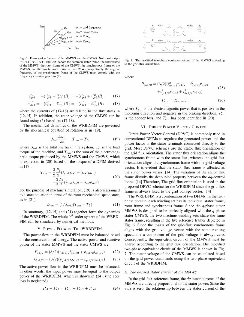
Fig. 6. Frames of reference of the MMWS and the CMWS. Note: subscripts‘s’, ‘r1’, ‘r2’, ‘e1’, and ‘e2’ denote the common stator frame, the rotor frameof the MMWS, the rotor frame of the CMWS, the synchronous frame of theMMWS, and the synchronous frame of the CMWS, respectively; the angularfrequency of the synchronous frame of the CMWS must comply with thefrequency criterion given in (2).
vr1qr1 = −(ir1qr1 + ir1 ′qr1 )Rf = −(ir1qr1 + ir2qr2)Rf (17)
vr1dr1 = −(ir1dr1 + ir1 ′dr1 )Rf = −(ir1dr1 − ir2dr2)Rf (18)
where the currents of (17-18) are related to the flux states in(12-15). In addition, the rotor voltage of the CMWS can befound using (5) based on (17-18).
The mechanical dynamics of the WRBDFIM are governedby the mechanical equation of rotation as in (19),
Jtotdωrm
dt= Tem − TL (19)
where Jtot is the total inertia of the system, TL is the loadtorque of the machine, and Tem is the sum of the electromag-netic torque produced by the MMWS and the CMWS, whichis expressed in (20) based on the torque of a DFIM derivedin [17].
Tem =3
2
P1
2(λds1iqs1 − λqs1ids1)
+3
2
P2
2(λds2iqs2 − λqs2ids2)
(20)
For the purpose of machine simulation, (19) is also rearrangedto a state equation in terms of the rotor mechanical speed state,as in (21).
ωrm = (1/Jtot)(Tem − TL) (21)
In summary, (12-15) and (21) together form the dynamicsof the WRBDFIM. The whole 9th order system of the WRBD-FIM can be simulated by numerical methods.
V. POWER FLOW OF THE WRBDFIM
The power-flow in the WRBDFIM must be balanced basedon the conservation of energy. The active power and reactivepower of the stator MMWS and the stator CMWS are
Ps1/2 = (3/2)(vds1/2ids1/2 + vqs1/2iqs1/2) (22)
Qs1/2 = (3/2)(vqs1/2ids1/2 − iqs1/2vds1/2) (23)
The active power flow in the WRBDFIM must be balanced;in other words, the input power must be equal to the outputpower of the WRBDFIM, which is shown in (24), (the coreloss is neglected)
Ps1 + Ps2 = Pem + Pcu1 + Pcu2 (24)
Rs1 Lls1 Llr1 Rr1
Lm1
ωe1λds1 ωsl1λdr1
Rs1 Lls1 Llr1 Rr1
Lm1
ωe1λqs1 ωsl1λqr1
vqs1
+
_
vds1
+
_
vqr1
vdr1
+
_
+
_
λqs1 λqr1
λds1 λdr1
iqs1
ids1
iqr1
idr1
Fig. 7. The modified two-phase equivalent circuit of the MMWS accordingto the grid-flux orientation.
where
Pcu1/2 = (3/2)(i2qs1/2rs1/2 + i2ds1/2rs1/2
+i2qr1/2rr1/2 + i2dr1/2rr1/2)(25)
Pem = Temωrm (26)
where Pem is the electromagnetic power that is positive in themotoring direction and negative in the braking direction, Pcu
is the copper loss, and Tem has been identified in (20).
VI. DIRECT POWER VECTOR CONTROL
Direct Power Vector Control (DPVC) is commonly used inconventional DFIMs to regulate the generated power and thepower factor at the stator terminals connected directly to thegrid. Most DPVC schemes use the stator flux orientation orthe grid flux orientation. The stator flux orientation aligns thesynchronous frame with the stator flux, whereas the grid fluxorientation aligns the synchronous frame with the grid-voltagevector. It is evident that the stator flux frame is affected asthe stator power varies. [14] The variation of the stator fluxframe disturbs the decoupled property between the dq-controlloops. [14] Therefore, The grid flux orientation is used in theproposed DPVC scheme for the WRBDFIM since the grid fluxframe is always fixed to the grid voltage vector. [14]
The WRBDFIM is a combination of two DFIMs. In the two-phase domain, each winding set has its individual stator frame,rotor frame and synchronous frame. Since the q-phase statorMMWS is designed to be perfectly aligned with the q-phasestator CMWS, the two machine winding sets share the samestator frame, resulting in the five reference frames depicted inFig. 6. Since the q-axis of the grid-flux synchronous framealigns with the grid voltage vector with the same rotatingspeed, the d-component of the grid voltage is always zero.Consequently, the equivalent circuit of the MMWS must bealtered according to the grid flux orientation. The modifiedtwo-phase equivalent circuit of the MMWS is shown in Fig.7. The stator voltage of the CMWS can be calculated basedon the grid power commands using the two-phase equivalentcircuit of the WRBDFIM.
A. The desired stator current of the MMWS
In the grid-flux reference frame, the dq stator currents of theMMWS are directly proportional to the stator power. Since thevds1 is zero, the relationship between the stator current of the

MMWS and the main machine stator power are reduced to thefollowing by using (22-23)
Ps1 = (3/2)(ve1qs1ie1qs1) (27)
Qs1 = (3/2)(ve1qs1ie1ds1) (28)
Assuming the desired grid active power and reactive powerare P ∗s1 and Q∗s1, the required stator current can be calculatedbelow by rearranging (27) and (28)
ie1∗qs1 = (2P ∗s1)/(3ve1qs1) (29)
ie1∗ds1 = (2Q∗s1)/(3ve1qs1) (30)
B. The desired stator flux of the MMWS
The required stator flux to supply the desired grid power canbe calculated based on the desired stator current. The statorvoltage equations can be drawn based on Fig. 7, i.e.
ve1qs1 = ie1qs1rs1 + ωe1λe1ds1 +
dλe1qs1dt
(31)
0 = ie1ds1rs1 − ωe1λe1qs1 +
dλe1ds1dt
(32)
By rearranging (31) and (32), the required stator flux of theMMWS can be calculated as
λe1∗qs1 =
∫ve1qs1 − ie1∗qs1rs1 − ωe1λ
e1∗ds1 (33)
λe1∗ds1 =
∫−ie1∗ds1rs1 + ωe1λ
e1∗qs1 (34)
C. The desired rotor current of the MMWS
By the definition of the stator flux, the rotor current isrelated to the stator flux and stator current as shown below
λe1qs1 = Ls1ie1qs1 + Lm1i
e1qr1 (35)
λe1ds1 = Ls1ie1ds1 + Lm1i
e1dr1 (36)
If the desired stator current and the stator flux have beencomputed using (29), (30), (33), and (34), the desired rotorcurrent can be identified by rearranging (35) and (36), as
ie1∗qr1 = (λe1∗qs1 − Ls1ie1∗qs1)/Lm1 (37)
ie1∗dr1 = (λe1∗ds1 − Ls1ie1∗ds1)/Lm1 (38)
D. The desired rotor flux of the MMWS
The desired rotor flux can be obtained based on its defi-nition, since the desired stator current and rotor current havebeen identified. The desired dq rotor fluxes are
λe1∗qr1 = Lr1ie1∗qr1 + Lm1i
e1∗qs1 (39)
λe1∗dr1 = Lr1ie1∗dr1 + Lm1i
e1∗ds1 (40)
λqr1*
P ∫
ωsl1λdr1
+
_
+
+
+ +_ _
vqr1*
rr1iqr1 ωsl1λdr1
λqr1
Machine Plant
λdr1*
P ∫
ωsl1λqr1
+
_
+_
+ +_ +
vdr1*
rr1idr1 ωsl1λqr1
λdr1
Machine Plant
Fig. 8. Inner loop flux regulator of the MMWS.
E. The desired rotor voltage of the MMWS
Normally, calculating the desired rotor voltage using therotor current and rotor flux involves the application of thedifferentiators, as in
ve1∗qr1 =dλe1∗qr1
dt+ ωsl1λ
e1∗dr1 + ie1∗qr1rr1 (41)
ve1∗dr1 =dλe1∗dr1
dt− ωsl1λ
e1∗qr1 + ie1∗dr1rr1 (42)
In order to improve the dynamic response of the WRBDFIM,a flux regulator [14] is proposed, forming the inner feedbackloop of the main dq control loop. The flux regulator is shownin Fig. 8. The main drawback of the flux regulator is therequirement that the instantaneous rotor flux be used as thefeedback signal, which necessitates additional designs for therotor-flux observer of the MMWS. The reason why only theproportional (P) control element is sufficient in the inner loopis because the integrator physically appearing in the machineplant can serve the purpose of eliminating the steady stateerror. [14] The control effort of the flux regulator is the rotorvoltage of the MMWS.
F. The desired rotor voltage and current of the CMWS
The desired rotor voltage and current of the MMWS canbe transferred to the CMWS. The rotor voltage and current ofthe CMWS can be obtained by computing a vector rotationas shown in Fig. 4, using (4) and (5). Thus, the desired rotorvoltage and current are
ve2∗qr2 = ve1∗qr1 (43)
ve2∗dr2 = −ve1∗dr1 (44)
ie2∗qr2 = −ie1∗qr1 (45)
ie2∗dr2 = ie1∗dr1 (46)
The superscripts in (43-46) highlight the difference in frameof reference when making the transfer from the MMWS to theCMWS.

Ps1*
PI
PIQs1
*
Rs1
vqs1
+_
Ps1
Qs1
_+
×
×
ωe1
__
+
+
+_
∫ 1/Lm1
1/Lm1
Ls1
Ls1
+
_
+_
iqs1*
ids1*
λqs1*
λds1*
Lr1
Lr14
Lm1
Lm1
+
+
+
+
iqr1*
idr1*
P
P
λqr1*
λdr1*
λqr1
λdr1
ωsl1λdr1
ωsl1λqr1
+ _
+ _
++
+_
1
1
1
1
Rs1
Rr2
Rr2
× ωsl1
× ωsl1
iqr2*
idr2*
_
+
+
+
_
_
+
+
∫
∫
∫
vqr2*
vdr2*
1/Lm2
λqr2*
λdr2*
1/Lm2
Lr2
Lr2
+
_
+ _
Ls2
Ls2
Lm2
Lm2
++
+
+
iqs2*
ids2*
P
P
+ ++
+_
+_
_
λqs2
λds2
ωe2λds2
ωe2λqs2
λds2*
λqs2* vqs2
*
vds2*
vqr1*
vdr1*
Fig. 9. The proposed DPVC scheme for the WRBDFIM.
G. The desired rotor flux of the CMWS
Using the same methodology as shown in (33-34), thedesired rotor flux can be calculated based on the desired rotorvoltage and current of the CMWS, as shown in (43-46). Byfollowing the equivalent circuits shown in Fig. 5, the desireddq rotor fluxes of the CMWS are
λe2∗qr2 =
∫ve2∗qr2 − ie2∗qr2rr2 + ωsl1λ
e2∗dr2 (47)
λe2∗dr2 =
∫ve2∗dr2 − ie2∗dr2rr2 − ωsl1λ
e2∗qr2 (48)
It should be noted that the speed of the synchronous frameof the CMWS must comply with the criterion given in (2).Therefore, the speed voltage source on the rotor side of Fig.5 is evaluated to be equal to −ωsl1, which is directly used in(47) and (48).
H. The desired stator current and stator flux of the CMWS
In like manner, the desired stator current and stator flux ofthe CMWS are calculated by following the same methodologydeveloped in (37-40). They are expressed as follows
ie2∗qs2 = (λe2∗qr2 − Lr2ie2∗qr2)/Lm2 (49)
ie2∗ds2 = (λe2∗dr2 − Lr2ie2∗dr2)/Lm2 (50)
λe2∗qs2 = Ls2ie2∗qs2 + Lm2i
e2∗qr2 (51)
λe2∗ds2 = Ls2ie2∗ds2 + Lm2i
e2∗dr2 (52)
I. The desired stator voltage of the CMWS
The calculation of the desired stator voltage of the CMWSalso involves the application of the differentiators. The voltageequations on the stator side of the CMWS are
ve2∗qs2 = ie2∗qs2rs2 + ωe2λe2∗ds2 +
dλe2∗qs2
dt(53)
ve2∗ds2 = ie2∗ds2rs2 − ωe2λe2∗qs2 +
dλe2∗ds2
dt(54)
Again, another set of flux regulators are used here for each dqcontrol loop in order to improve the dynamic response. Theflux regulators are exactly the same as those of the MMWS,which are shown in Fig. 8. The instantaneous stator fluxsignal of the CMWS is also required, which must be obtainedby observers. The control effort of the flux-controller is thevoltage that drives the stator terminal of the CMWS.
J. Outer power feedback loop
The algorithm discussed so far is mainly the feed-forwardportion of the DPVC. A set of proportional and integral (PI)controllers must be added as the outer feedback loops of theDPVC scheme to improve the stability and tracking capabilityof the WRBDFIM. The instantaneous values of the Ps1 andQs1 are used as the feedback signals, which can be easilymeasured on the stator winding of the MMWS. Since the PIcontroller is added as the outer feedback loop for each dqcontrol loop, the proportionalities derived in (29) and (30)are already embedded in the PI control algorithm. Thus, thecontrol effort of the PI controller is the desired stator current.The completed DPVC control scheme is shown in Fig. 9,which represents the feed-forward and outer feedback controlalgorithms pictorially using block diagrams.
VII. SIMULATION RESULTS
The proposed 9th-order dynamic model and the DPVCscheme of the WRBDFIM are simulated in Simulink usingthe two machines detailed in Table I. The voltage of the grid-connected stator of the MMWS is set to its rated terminalvoltage of 220V (line-line RMS at 60 Hz). The stator terminalsof the CMWS are directly connected to the output of theDPVC. The numerical method is set to the ‘Stiff-Rosenbrock’method in the ODE solver, with the relative tolerance set to‘1e-6’.

TABLE IWINDING SETS SPECIFICATIONS
MMWS CMWSParameters Parameters
Pole Pairs P 2 1Rated Frequency fe (Hz) 60 60Rated Power PR (kW) 3.73 3Rated Voltage (LL) Vs (VRMS) 220 220Connection Star StarStator Resistance Rs (Ω) 0.531 0.403Stator Leakage Inductance Lls (H) 0.00252 0.0039Magnetizing Inductance Lm (H) 0.0847 0.128Rotor Resistance Rr (Ω) 0.408 0.484Rotor Leakage Inductance Llr (H) 0.00252 0.0039Fictitious Resistance Rf (Ω) 100000Total Inertia Jtot (kgm2) 0.2
A. Steady-state performance
The steady-state performance of the WRBDFIM can beobtained by disabling the mechanical dynamics of the machinemodel, leaving only the remaining 8th-order electrical dynam-ics active. The rotor speed can be set to any constant values,as can the voltage source that drives the stator terminals ofthe CMWS. The grid-connected stator voltage of the MMWSis fixed to its rated voltage. The electromagnetic torque of theWRBDFIM is computed by using (20), where the current andflux states are simulated by the constant speed dynamic modelof the WRBDFIM.
Fig. 10 shows the steady-state torque speed curve obtainedusing the constant speed simulation model of the WRBDFIM.The torque speed curve is essentially a summation of twoindividual torque-speed curves having different pole numbers.From Fig. 10, it is evident that the torque-speed curves vary asthe magnitude (|v2|) and the phase-shift (φ) change, makingthe WRBDFIM suitable for wind turbine applications. When‘vs2 = 0’, the WRBDFIM acts a cascaded induction machine.The synchronous speed, i.e. 1200 RPM shown in Fig. 10,exactly matches the synchronous speed predicted using (3).
B. Dynamic response to a step change in stator power
To investigate for the transient response to a step change instator power, the rotor speed of the WRBDFIM model is nolonger set to a constant. Both the electrical and mechanicaldynamics are now active in the machine model, resulting ina 9th-order system. The excitation at the stator terminal ofthe MMWS remains at the rated voltage. The output of thecontrollers directly drives the stator terminals of the CMWS.The proposed DPVC scheme for the WRBDFIM utilizes theinstantaneous values of Ps1, Qs1, λqr1, λdr1, λqs2, and λds2 asthe feedback signals. In practice, Ps1 and Qs1 can be measuredby power meters at the stator terminal of the MMWS. λqr1,λdr1, λqs2, and λds2 must be observed using the stator currentand voltage available at the stator terminals of the MMWSand CMWS. For simulation purposes, the Ps1 and Qs1 can be
TABLE IIFINE-TUNED CONTROLLER GAINS
q-loop Values d-loop Values
Outer-loop P Gain KPo 0.8 0.05Outer-loop I Gain KIo 17 36Inner-loop MMWS P Gain KPi1 0.15 0.15Inner-loop CMWS P Gain KPi2 0.1 0.1
100 200 300 400 500 600 700 800 900 1000 1100 1200 1300 1400 1500−200
−150
−100
−50
0
50
Rotor Speed (RPM)
Tor
que
(Nm
)
|vs2
| = 0 & Φ = 0
|vs2
| = 0.1|vs1
| & Φ = 0
|vs2
| = 0.3|vs1
| & Φ = 7π/6
|vs2
| = 0.1|vs1
| & Φ = 11π/9
Fig. 10. Torque-Speed curves of the WRBDFIM with different vs2.
calculated using the flux states of the machine model basedon (22-23), whereas λqr1, λdr1, λqs2, and λds2 are the fluxstates of the machine model listed in (12-15).
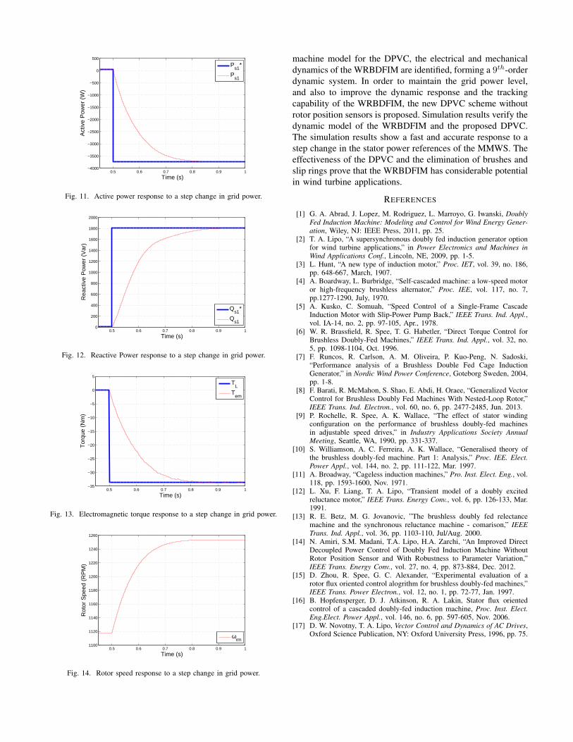
The gains of the controllers are fine-tuned, and summarizedin Table II. Before the stator power references of the MMWSare suddenly changed, the machine is running at 1120 RPMwith no load. At t = 0.5 s, the active power reference andreactive power reference suddenly change to −3730 W and1807 Var respectively, resulting in a power factor equal to0.9, lagging. The load torque is set to −32.4 Nm at t = 0.5 s,which is the same as the Tem produced by the WRBDFIM inits steady-state.
The transient active power and reactive power response tothe sudden change in the grid power references are shownin Fig. 11 and Fig. 12, respectively. The power responses ofthe WRBDFIM show 0% overshoot and 0% steady-state error.The active power and reactive power take 0.3 s and 0.35 s toreach steady-state, respectively. The corresponding torque andspeed of the WRBDFIM are also shown in Fig. 13 and Fig.14, respectively. Since the load torque has been set to equalto the electromagnetic torque, the rotor speed is stable in thesteady-state, as indicated in Fig. 14.
VIII. CONCLUSION
In this paper, an alternative type of BDFIM is proposed,aiming to eliminate the circulating stator current due tomagnetic unbalance in the single stator winding sets ofconventional BDFIMs and effectively suppress the unwantedharmonics created by nest-loop rotor. The proposed WRBD-FIM is easier to manufacture comparing to the conventionalBDFIMs. A vector rotation is derived for the junction circuitbetween the MMWS and the CMWS. In order to construct a
0.5 0.6 0.7 0.8 0.9 1−4000
−3500
−3000
−2500
−2000
−1500
−1000
−500
0
500
Time (s)
Act
ive
Pow
er (
W)
Ps1
*
Ps1
Fig. 11. Active power response to a step change in grid power.
0.5 0.6 0.7 0.8 0.9 10
200
400
600
800
1000
1200
1400
1600
1800
2000
Time (s)
Rea
ctiv
e P
ower
(V
ar)
Qs1
*
Qs1
Fig. 12. Reactive Power response to a step change in grid power.
0.5 0.6 0.7 0.8 0.9 1−35
−30
−25
−20
−15
−10
−5
0
5
Time (s)
Tor
que
(Nm
)
TL
Tem
Fig. 13. Electromagnetic torque response to a step change in grid power.
0.5 0.6 0.7 0.8 0.9 11100
1120
1140
1160
1180
1200
1220
1240
1260
Time (s)
Rot
or S
peed
(R
PM
)
ωrm
Fig. 14. Rotor speed response to a step change in grid power.
machine model for the DPVC, the electrical and mechanicaldynamics of the WRBDFIM are identified, forming a 9th-orderdynamic system. In order to maintain the grid power level,and also to improve the dynamic response and the trackingcapability of the WRBDFIM, the new DPVC scheme withoutrotor position sensors is proposed. Simulation results verify thedynamic model of the WRBDFIM and the proposed DPVC.The simulation results show a fast and accurate response to astep change in the stator power references of the MMWS. Theeffectiveness of the DPVC and the elimination of brushes andslip rings prove that the WRBDFIM has considerable potentialin wind turbine applications.
REFERENCES
[1] G. A. Abrad, J. Lopez, M. Rodriguez, L. Marroyo, G. Iwanski, DoublyFed Induction Machine: Modeling and Control for Wind Energy Gener-ation, Wiley, NJ: IEEE Press, 2011, pp. 25.
[2] T. A. Lipo, “A supersynchronous doubly fed induction generator optionfor wind turbine applications,” in Power Electronics and Machines inWind Applications Conf., Lincoln, NE, 2009, pp. 1-5.
[3] L. Hunt, “A new type of induction motor,” Proc. IET, vol. 39, no. 186,pp. 648-667, March, 1907.
[4] A. Boardway, L. Burbridge, “Self-cascaded machine: a low-speed motoror high-frequency brushless alternator,” Proc. IEE, vol. 117, no. 7,pp.1277-1290, July, 1970.
[5] A. Kusko, C. Somuah, “Speed Control of a Single-Frame CascadeInduction Motor with Slip-Power Pump Back,” IEEE Trans. Ind. Appl.,vol. IA-14, no. 2, pp. 97-105, Apr., 1978.
[6] W. R. Brassfield, R. Spee, T. G. Habetler, “Direct Torque Control forBrushless Doubly-Fed Machines,” IEEE Trans. Ind. Appl., vol. 32, no.5, pp. 1098-1104, Oct. 1996.
[7] F. Runcos, R. Carlson, A. M. Oliveira, P. Kuo-Peng, N. Sadoski,“Performance analysis of a Brushless Double Fed Cage InductionGenerator,” in Nordic Wind Power Conference, Goteborg Sweden, 2004,pp. 1-8.
[8] F. Barati, R. McMahon, S. Shao, E. Abdi, H. Oraee, “Generalized VectorControl for Brushless Doubly Fed Machines With Nested-Loop Rotor,”IEEE Trans. Ind. Electron., vol. 60, no. 6, pp. 2477-2485, Jun. 2013.
[9] P. Rochelle, R. Spee, A. K. Wallace, “The effect of stator windingconfiguration on the performance of brushless doubly-fed machinesin adjustable speed drives,” in Industry Applications Society AnnualMeeting, Seattle, WA, 1990, pp. 331-337.
[10] S. Williamson, A. C. Ferreira, A. K. Wallace, “Generalised theory ofthe brushless doubly-fed machine. Part 1: Analysis,” Proc. IEE. Elect.Power Appl., vol. 144, no. 2, pp. 111-122, Mar. 1997.
[11] A. Broadway, “Cageless induction machines,” Pro. Inst. Elect. Eng., vol.118, pp. 1593-1600, Nov. 1971.
[12] L. Xu, F. Liang, T. A. Lipo, “Transient model of a doubly excitedreluctance motor,” IEEE Trans. Energy Conv., vol. 6, pp. 126-133, Mar.1991.
[13] R. E. Betz, M. G. Jovanovic, ”The brushless doubly fed relectancemachine and the synchronous reluctance machine - comarison,” IEEETrans. Ind. Appl., vol. 36, pp. 1103-110, Jul/Aug. 2000.
[14] N. Amiri, S.M. Madani, T.A. Lipo, H.A. Zarchi, “An Improved DirectDecoupled Power Control of Doubly Fed Induction Machine WithoutRotor Position Sensor and With Robustness to Parameter Variation,”IEEE Trans. Energy Conv., vol. 27, no. 4, pp. 873-884, Dec. 2012.
[15] D. Zhou, R. Spee, G. C. Alexander, “Experimental evaluation of arotor flux oriented control alogrithm for brushless doubly-fed machines,”IEEE Trans. Power Electron., vol. 12, no. 1, pp. 72-77, Jan. 1997.
[16] B. Hopfensperger, D. J. Atkinson, R. A. Lakin, Stator flux orientedcontrol of a cascaded doubly-fed induction machine, Proc. Inst. Elect.Eng.Elect. Power Appl., vol. 146, no. 6, pp. 597-605, Nov. 2006.
[17] D. W. Novotny, T. A. Lipo, Vector Control and Dynamics of AC Drives,Oxford Science Publication, NY: Oxford University Press, 1996, pp. 75.


![089 ' # '6& *#0 & 7development within the insect vector, ( IV ) preventing transmission to uninfected host(s). within the insect vector (Table 2) [39-48], or that are expressed on](https://img.pdfslide.net/doc/110x75/611232bf3e9bce2b69465b8c/089-6-0-7-development-within-the-insect-vector-iv-preventing.jpg)