Embed Size (px)
Citation preview

HSEHealth & Safety
Executive
Safety implications of European risk basedinspection and maintenance methodology
Prepared by Mitsui Babcock for the Health and Safety Executive 2005
RESEARCH REPORT 304

HSEHealth & Safety
Executive
Safety implications of European risk basedinspection and maintenance methodology
BWO ShepherdMitsui Babcock Technology
Porterfield RoadRenfrewPA4 8DJ
This report describes work for HSE to review the safety related implications of the European researchand development project “Risk Based Inspection and Maintenance Procedures for European Industry”(RIMAP)
RIMAP is partly funded by the European Commission under EC Framework Programme 5. MitsuiBabcock have reviewed for HSE the implications of RIMAP for health and safety in the UK.
A number of relevant issues have been highlighted to HSE, both during the course of this project, andin this final report. There have been several cases where Mitsui Babcock has provided feedback onHSE’s views to the RIMAP consortium and this is believed to have been beneficial both for the RIMAPproject and in helping to achieve HSE’s objectives regarding health and safety within the UK, withparticular respect to operation of process and pressure plant.
This report and the work it describes were funded by the Health and Safety Executive (HSE). Itscontents, including any opinions and/or conclusions expressed, are those of the authors alone and donot necessarily reflect HSE policy.
HSE BOOKS
ii
© Crown copyright 2005
First published 2005
ISBN 0 7176 2950 3
All rights reserved. No part of this publication may bereproduced, stored in a retrieval system, or transmitted inany form or by any means (electronic, mechanical,photocopying, recording or otherwise) without the priorwritten permission of the copyright owner.
Applications for reproduction should be made in writing to: Licensing Division, Her Majesty's Stationery Office, St Clements House, 2-16 Colegate, Norwich NR3 1BQ or by e-mail to [email protected]

SUMMARY
RIMAP (Risk Based Inspection and Maintenance Procedures for European Industry) is a European research and technological development project partly funded by the European Commission under EC Framework Programme 5. Mitsui Babcock have reviewed for HSE the implications of RIMAP for health and safety in the UK.
A number of relevant issues have been highlighted to HSE, both during the course of this project, and in this final report. There have been several cases where Mitsui Babcock has provided feedback on HSE’s views to the RIMAP consortium and this is believed to have been beneficial both for the RIMAP project and in helping to achieve HSE’s objectives regarding health and safety within the UK, with particular respect to operation of process and pressure plant.
CONCLUSIONS
The documentation produced by RIMAP has been very extensive. It is considered extremely unlikely that any individual will read all of the reports produced. The higher level documents present the main RIMAP principles and general procedures. The more detailed “lower level” documents vary in detail and, in some cases, in quality.
The main result of RIMAP is likely to be an increased awareness of risk based inspection and maintenance (RBIM) across Europe. Its main role is likely to be as a framework against which more detailed risk based approaches can be assessed, i.e. as a general European “good practice”. The two documents which are considered to be of most help in establishing detailed RBIM programmes are the Petrochemical and Chemical Workbooks, both of which are considered (by Mitsui Babcock) to present sound approaches, although neither appears to propose “speculative” or sample inspections of plant deemed to be low risk. There is therefore a strong reliance on correct identification of probability of failure (which assumes correct assessment of all potential degradation mechanisms and failure modes)
Two important areas where HSE / Mitsui Babcock feedback was provided to the RIMAP consortium, and where changes subsequently occurred, were in the approach to ALARP (as low as reasonably practical) and the use of the HSE Best Practice audit tool.
The ALARP principle to risk acceptance criteria was highlighted to RIMAP as a preferred approach compared to the achievement of a total acceptable risk for a facility regardless of the risk for an individual plant item. The RIMAP procedure now addresses ALARP criteria although it is not clear whether this was in response to Mitsui Babcock’s comments or to comments from other RIMAP members.
The audit tool in the HSE “Best Practice for Risk Based Inspection as a Part of Plant Integrity Management” was used by Mitsui Babcock to assess a draft of the RIMAP procedure, and the results passed to the RIMAP consortium. This resulted in RIMAP adopting this approach, and developing a checklist which is both more detailed than the HSE audit tool, and which includes a scoring system. If this RIMAP “Features List” is used within the UK, it should provide at least the same level of assurance as the HSE audit tool checklist. This is considered to be an important achievement.
iii

iv

CONTENTS
SUMMARY .......................................................................................................................... iii CONCLUSIONS .................................................................................................................. iii
Contents.................................................................................................................................. v1 INTRODUCTION.......................................................................................................... 1 2 OVERVIEW OF RIMAP ............................................................................................... 1
2.1 RIMAP Programme............................................................................................... 1 2.2 RIMAP Consortium ............................................................................................... 1 2.3 RIMAP Workscope................................................................................................ 2
3 OVERVIEW OF MITSUI BABCOCK WORK................................................................ 2 4 SAFETY RELATED ISSUES IDENTIFIED DURING PROJECT.................................. 3
4.1 RIMAP Framework................................................................................................ 3 4.2 RIMAP Generic Procedure ................................................................................... 4 4.3 RIMAP Risk Assessment Methods ....................................................................... 4 4.4 Application Workbooks ......................................................................................... 5 4.5 Demonstrations..................................................................................................... 6
5 CONCLUSIONS........................................................................................................... 6 Appendix 1 Review of Generic RBIM Framework (at draft stage) ........................................ 10 Appendix 2 Extract from RIMAP Procedure describing ALARP ........................................... 15 Appendix 3 Assessment of RIMAP Procedure using Features Checklist ............................. 17 Appendix 4 Summary of RIMAP Risk Assessment Methods................................................ 94 Appendix 5 Summary of Workbooks................................................................................... 106
v

vi
1 INTRODUCTION
This report describes work for HSE to review the safety related implications of the European research and development project “Risk Based Inspection and Maintenance Procedures for European Industry” (RIMAP)
The HSE contract reference D4059 was placed at the end of December 2003 and the work has proceeded in parallel with the RIMAP project.
2 OVERVIEW OF RIMAP
2.1 RIMAP Programme
RIMAP was partly funded by the European Commission (EC) under the Fifth Framework “Competitive and Sustainable Growth” Programme. It consisted of two main parts – a research and technological development (RTD) project, and a thematic network.
The RIMAP RTD project started in March 2001 with a planned duration of 3 years but due to a required extension it did not finish until August 2004. The first two years were planned to cover development activities while the final year covered demonstration activities. The RIMAP “thematic network” ran in parallel with the RTD project and is intended to act as a route for discussion and dissemination of the non-confidential aspects of the RIMAP project, and as a forum for exchange of views on risk based inspection and maintenance in general. Mitsui Babcock is a member of the RTD project, and HSE is a member of the Thematic Network. In this progress report reference to RIMAP means the RTD project.
2.2 RIMAP Consortium
The RIMAP consortium consisted of the following partners:
• DnV (Norway) – project coordinator
• Bureau Veritas (France)
• MPA (Germany)
• VTT (Finland)
• TNO (Netherlands)
• Mitsui Babcock (UK)
• ExxonMobil (UK)
• EnBW (Germany)
• Siemens (Germany)
• JRC Petten (EC)
• ESB (Ireland)
• Corus (UK)
• DOW (Netherlands)
• Solvay (Belgium)
1
2.3 RIMAP Workscope
The RIMAP project consisted of the following work packages:
WP1 Review of current practice
WP2 Development of generic risk based inspection and maintenance methods
WP3 Development of risk assessment methods
WP3.1 Methods for determining probability of failure (POF)
WP3.2 Methods for determining consequence of failure (COF)
WP3.3 Inspection and monitoring effectiveness
WP3.4 Risks due to human errors, and risk calculation
WP4 Production of Application Workbooks for each of four industrial sectors: petrochemical, power generation, steel, chemical
WP5 Validation of RIMAP methodology (verification by industrial partners)
WP6 Project management by DnV
WP Demo 1 Demonstration of RIMAP methodology within petrochemical industry
WP Demo 2 Demonstration of RIMAP methodology within power industry
WP Demo 3 Demonstration of RIMAP methodology within steel industry
WP Demo 4 Demonstration of RIMAP methodology within chemical industry
WP Demo Support Coordination of demonstrations to ensure consistency of approach and quality.
The deliverables from the RIMAP project are in the form of reports and are listed in Table 1. These are classified as either main deliverables D1, D2 etc. (provided to EC) or internal deliverables I1, I2 etc. (provided within consortium).
Although draft copies of some of these reports have been issued to HSE during the course of the project, it is not proposed to issue the final reports (unless specifically requested) since many will shortly be available for public downloading from the RIMAP web page http://research.dnv.com/rimap/
3 OVERVIEW OF MITSUI BABCOCK WORK
Mitsui Babcock’s work for HSE has involved reviewing the results, reports and recommendations from the RIMAP project as they have been produced, and highlighting to HSE aspects which have particular safety related implications. Feedback on HSE’s views has been provided to the RIMAP consortium where appropriate. It was felt that this early regulatory feedback would be welcomed by RIMAP, although it was recognised that the RIMAP consortium had no commitment to address these comments.
2

HSE have been kept informed of progress and the main issues arising through a series of progress reports and meetings, generally at 6 monthly intervals.
4 SAFETY RELATED ISSUES IDENTIFIED DURING PROJECT
The main issues which have been identified as likely to be of particular interest to HSE follow. Note that many of these have already been raised with HSE through the periodic progress reports and meetings. There have been several cases where feedback has been provided to the RIMAP consortium following which changes were made to RIMAP documents. Note that it was not always possible to determine whether a change was made directly as a result of Mitsui Babcock / HSE feedback, or whether it was as a result of comments from other members of the RIMAP project (or thematic network).
4.1 RIMAP Framework
The Generic RIMAP Framework document was reviewed in detail at an early stage (Version 1, issue date 12/03/03). All aspects which were considered to have safety related implications were identified and the results of this review are presented in Appendix 1. Issues which were considered to be particularly important are highlighted in bold and these were subject to further discussion between Mitsui Babcock and HSE. Following these discussions feedback on HSE’s views was forwarded to the RIMAP consortium.
During the course of the RIMAP project the philosophy of what should be in the Framework document altered, and it changed from a 54 page technical overview of the main principles of RIMAP to a 9 page overview of the RIMAP scope and process. Many of the technical aspects were covered instead in the RIMAP Generic Procedure (see below).
However the feedback provided by Mitsui Babcock / HSE was still relevant, albeit to sections now incorporated in the Generic Procedure document.
One of the main changes to RIMAP documentation which is consistent with the Mitsui Babcock / HSE feedback is that the RIMAP approach to risk acceptance criteria now includes the ALARP approach (as low as reasonably practical) whereas the draft Framework document reviewed included a criterion that if the total risk was below a predefined limit then no action was required (see Appendix 1 comment 4).
Appendix 2 presents an extract from the final version of the RIMAP Generic Procedure which addresses ALARP and is much more acceptable than the approach commented upon (although the original approach is still described in an introductory section of the Generic Procedure)
A second important area where changes have been made is that the RIMAP documentation now stresses the importance of linking each Probability of Failure to the corresponding Consequence of Failure (as opposed to combining the Probability of Failure from each degradation mechanism into an integrated value) – see Appendix 1 comments 5 and 25.
There are however areas where it is not evident that Mitsui Babcock / HSE concerns have been addressed. These include the need for guidance on how uncertainties in PoF and CoF can be determined (Appendix 1 comments 22 and 27), and the benefits of speculative or spot check inspections for equipment where risk may have been determined as low but consequence of failure is high. (Appendix 1 comment 24).
3

4.2 RIMAP Generic Procedure
The Generic RIMAP Procedure was reviewed at Draft 6 stage and assessed against the audit tool checklist which is Appendix B of the HSE “Best Practice for Risk Based Inspection”. The results were presented in the second progress report issued to HSE and discussed at a subsequent progress meeting when it was agreed to provide a copy of this assessment to the RIMAP consortium.
Mitsui Babcock also highlighted the relevance to the RIMAP consortium of both the HSE Best Practice document, and the HSL report on the project “Risk Based Inspection – a Case Study of Onshore Process Plant” in which Mitsui Babcock participated.
The RIMAP consortium has subsequently made particular use of the HSE Best Practice audit tool, and has produced a “features checklist” which is based on the audit tool, but with inclusion of additional points to be checked and a scoring system.
Three of the RIMAP partners performed independent assessments of the final RIMAP Generic Procedure (and the more detailed Risk Assessment Procedures produced under RIMAP WorkPackage 3) using the features checklist. The results are presented in Appendix 3.
4.3 RIMAP Risk Assessment Methods
The final version of the RIMAP document “Risk Assessment Methods for Use in RBIM” was reviewed and a summary presented to HSE at one of the progress meetings. The summary is included in this report as Appendix 4.
There are no issues in the main text of this RIMAP document which are considered contentious, although it is unlikely that most readers would read through the appendices, which contain more detailed guidance on various aspects, but are over 150 pages.
The most noteworthy points addressed by the document which relate to health and safety include the following:
• The document states that all potential causes should be listed for each failure mode with an analysis. It is stressed that the most serious failures are often the ones that the organisation has not prepared for and it is these failures that the RBIM methodology aims to anticipate and prevent.
• In order to be consistent when assessing risks, the probability of failure should generally be linked with the most expected consequence rather than the worst case scenario, otherwise the assessment will be too conservative. However consideration of the worst case scenario can be useful during initial screening.
• Health, safety and environmental consequences must be assessed for every failure mode. Assessment of business consequences is optional although it is recommended that these are included to make risk based methods economically attractive.
• Risk to personnel during inspection and maintenance activities should be considered, not just risk of plant failure.
• It is important to address the risk associated with failure of standby and safety systems. These systems are unlike other systems because the most important failure mode is the hidden failure, i.e. only discovered to be faulty when required or tested.
4

• The document states that consequence of failure should be determined separately for
the four elements safety, health, environment and business, and the overall consequence determined by the highest rating. The document recognises that this means that these different classifications need to be balanced so that one aspect does not dominate the risk assessment. However it should be noted that depending on how this balance is determined, a high business consequence could take priority over a medium health or safety consequence.
• There are no generic Key Performance Indicators (KPIs) for satisfactory safety health and environment levels. One possible approach which is proposed is to monitor the costs associated with SHE events. These could include costs associated with absenteeism and environmental accidents resulting in costs. Although it is insufficient to focus on cost when considering SHE issues, this approach could still help to compare SHE levels at different facilities.
• Increased awareness and training of staff can help to reduce SHE events during inspection and maintenance, and reporting of near misses should be encouraged.
4.4 Application Workbooks
RIMAP has produced four industry specific workbooks for the petrochemical, chemical, steel and power generation industries. The purpose of these workbooks is to provide more specific guidance on how to apply the RIMAP approach within these industrial sectors. Mitsui Babcock has previously reviewed the workbooks for the petrochemical, chemical and steel industries and provided a summary report to HSE at a progress meeting, which is attached to this final report as Appendix 5. The following provides a brief overview of Mitsui Babcock’s opinions of all four workbooks.
The workbooks have been produced by different members of the RIMAP consortium, and they vary in level of detail.
The Petrochemical Workbook is 78 pages long including appendices, and provides practical guidance on how to implement risk based inspection and maintenance at a petrochemical site. It is well written, generally clear, and the level of detail is considered appropriate (provides sufficient, but not too much, detail.) It could be used as a template to set up a practical RBIM programme. The document strongly champions a risk based approach to integrity management. No particular health and safety issues have been identified by Mitsui Babcock. It is not evident that there are any aspects in the approach described in the workbook which are unique to RIMAP.
The Chemical Workbook is 105 pages long. It provides clear practical guidance and addresses issues such as risk assessment of rotating systems, safety systems and stand by systems in more detail than the petrochemical workbook (which concentrates on static equipment). It is also more prescriptive in how RBIM should be performed, and although much of the approach is similar to that presented in the petrochemical workbook, it includes some of the aspects defined in the Dutch “KINT” RBI methodology, such as the explicit inclusion of a confidence factor when determining inspection intervals. Parts of the document reflect the RIMAP higher level documents more than the petrochemical workbook does. The main health and safety issue identified by Mitsui Babcock, is the statement that it is ineffective to try to detect “unknown” degradation mechanisms, whereas Mitsui Babcock consider that speculative inspections (e.g. spot checks or sampling) can play a useful role in detecting the presence of degradation which had been (incorrectly) identified as low probability, or had not been considered. Another issue is that HSE had identified in an earlier draft that corrosive property was not included in the list of consequence aspects. Mitsui Babcock pointed this out in a previous draft but it has not been addressed in the final
5
issue. However this is not considered particularly significant since the list in question is not a closed list – the methods to be used are based on but not limited to the aspects listed which include flammability, toxicity, energy release etc.)
The Steel Workbook is 50 pages, much of which is an overview of the RIMAP project and a guide to the main principles of RBIM. It provides less detailed guidance than the petrochemical or chemical workbooks. It explains the fundamental aspects of RBIM and identifies the types of degradation mechanisms common to steel plants. It is more likely to be suitable as a high level management strategy document for RBIM of steel plant, than as a step by step guide to setting up a detailed programme.
The main text of the Power Generation Workbook is 135 pages and there are 222 pages of appendices. This document has not been reviewed by Mitsui Babcock for two reasons. The first is that the length of the document is such that those who are not already familiar with it may not be inclined to read through it, so there is less likelihood of it being adopted by those working within the UK power generation industry. The second reason is that independent review by one of the RIMAP consortium members concluded that it was not considered suitable as a hands-on guide, and that it was a collection of more general RBIM aspects.
It is important to note that the above are “personal” views and the authors of the RIMAP workbooks have not had the opportunity to comment on them.
4.5 Demonstrations
Demonstrations were performed to help “validate” the RIMAP methodology. These were performed on petrochemical, chemical, steel and power generation plant in accordance with the respective workbooks.
There do not appear to be formal reports on these demonstrations at the time of writing (although RIMAP is officially finished), but there are powerpoint presentations. These presentations have all concluded that the demonstrations were successful in identifying improvements which could be made in current (prescriptive) inspection and maintenance plans at the demonstration plants.
It is not clear to what extent the demonstrations were performed strictly in accordance with the Workbooks (which could be difficult in some cases due to the lack of detail referenced above) and to what extent they relied instead on the knowledge of those who performed the demonstrations (each demonstration was facilitated by appropriate members of the RIMAP consortium).
It should also be noted that short term financial advantages of applying RBIM can become evident sooner than any health, safety or environmental disadvantages (due to increased failures), since the latter may only become evident in the longer term.
5 CONCLUSIONS
RIMAP (Risk Based Inspection and Maintenance Procedures for European Industry) is a European research and technological development project partly funded by the European Commission under EC Framework Programme 5. Mitsui Babcock have reviewed for HSE the implications of RIMAP for health and safety in the UK.
A number of relevant issues have been highlighted to HSE, both during the course of this project, and in this final report. There have been several cases where Mitsui Babcock has provided feedback on HSE’s views to the RIMAP consortium and this is believed to have been beneficial both for the RIMAP project and in helping to achieve HSE’s objectives
6
regarding health and safety within the UK, with particular respect to operation of process and pressure plant.
The RIMAP consortium consisted of 16 organisations. The documentation produced by RIMAP has been very extensive. It is considered extremely unlikely that any individual will read all of the reports produced. The higher level documents present the main RIMAP principles and general procedures. The more detailed “lower level” documents vary in detail and, in some cases, in quality.
The main result of RIMAP is likely to be an increased awareness of risk based inspection and maintenance (RBIM) across Europe. Its main role is likely to be as a framework against which more detailed risk based approaches can be assessed, i.e. as a general European “good practice”. The two documents which are considered to be of most help in establishing detailed RBIM programmes are the Petrochemical and Chemical Workbooks, both of which are considered (by Mitsui Babcock) to present sound approaches, although neither appears to propose “speculative” or sample inspections of plant deemed to be low risk. There is therefore a strong reliance on correct identification of probability of failure (which assumes correct assessment of all potential degradation mechanisms and failure modes)
Two important areas where HSE / Mitsui Babcock feedback was provided to the RIMAP consortium, and where changes subsequently occurred, were in the approach to ALARP (as low as reasonably practical) and the use of the HSE Best Practice audit tool.
The ALARP principle to risk acceptance criteria was highlighted to RIMAP as a preferred approach compared to the achievement of a total acceptable risk for a facility regardless of the risk for an individual plant item. The RIMAP procedure now addresses ALARP criteria although it is not clear whether this was in response to Mitsui Babcock’s comments or to comments from other RIMAP members.
The audit tool in the HSE “Best Practice for Risk Based Inspection as a Part of Plant Integrity Management” was used by Mitsui Babcock to assess a draft of the RIMAP procedure, and the results passed to the RIMAP consortium. This resulted in RIMAP adopting this approach, and developing a checklist which is both more detailed than the HSE audit tool, and which includes a scoring system. If this RIMAP “Features List” is used within the UK, it should provide at least the same level of assurance as the HSE audit tool checklist. This is considered to be an important achievement.
7

Table 1 List of RIMAP deliverables
Deliverable No.
Output from.
Nature of Deliverable and brief description
FINAL Reference Contributing partners
D6.1 WP6
WEB-page for the project (internal) updated during the project. Restricted.
http://research.dnv.com/rimap_ext
DNV
D1.1 WP1 Report on Current Practice. Restricted. 1-11-F-2004-01-1 DNV,, MPA,TNO,
ExxonMobil, MBEL
D2.1 WP2 Report on proposed RBIM-method. Restricted.
2-21-F-2004-01-1
DNV, BV, MPA, VTT, TUV, TNO, MBEL, EXXONMOBIL, JRC, CORUS, DOW
D2.2 WP2 Guideline document on RBIM - revision 1.0. Restricted.
Remains to be completed.
D2.2 WP2 Guideline document on RBIM - revision 2.0. Public.
2-22-F-2004-01-1
DNV, BV, MPA, VTT, TUV, TNO, MBEL, EXXONMOBIL, JRC, CORUS, DOW
D3.1 WP3 Risk Assessment Methods for use in RBIM. Restricted.
3-31-F-2004-01-1
DNV, BV, MPA, VTT, TNO, MBEL, EXXONMOBIL, CORUS, DOW, JRC
I3.1
Description and Classification of damage mechanisms & failure modes per industry sector
3-31-W-2003-01-3
I3.2
Consequence estimation; safety, environment, economic losses
3-32-W-2003-01-2
I3.3
Probability of failure estimation, different methods and level of detailing. PoF-updating.
3-33-W-2002-01-4
I3.4
Monitoring and inspection effectiveness for different components and systems and damage mechanisms.
3-34-W-2002-01-3
I3.5 Risk estimation and risk aggregation method.
3-35-W-2002-01-1
I3.6
Software (Excel format) with the PoF estimation method to be used in the RIMAP demonstrator project.
3-36-W-2003-01-1
Main parts included in: 3-31-F-2004-01
D4.1 WP4
Guidelines on how to set up inspection and maintenance programme. Restricted.
4-41-F-2004-01-1
DNV, BV, MPA, VTT, TÜV, MBEL, EXXONMOBIL, EnBW, CORUS, DOW, JRC
8

Deliverable No.
Output from.
Nature of Deliverable and brief description
FINAL Reference Contributing partners
D4.2 WP4
Guidelines on how to benchmark an inspection programme. Restricted.
4-42-F-2004-01-1
DNV, BV, MPA, VTT, TÜV, MBEL, EXXONMOBIL, EnBW, CORUS, DOW, JRC
D4.3 WP4
Work book per industry sector: - Petrochemical - Power - Steel - Chemical
4-43-F-2004-01-1 4-43-F-2004-02-1 4-43-F-2004-03-1 4-43-F-2004-04-1
DNV, BV, MPA, VTT, TÜV, MBEL, EXXONMOBIL, EnBW, CORUS, DOW, JRC
D5.1 WP5 Report on validation. Restricted. 5-51-F-2004-01-1
DNV, MPA, TNO, MBEL, EnBW, EXXONMOBIL, CORUS, DOW, JRC
I5.1 Plan for validation
DNV, MPA, TNO, MBEL, EnBW, EXXONMOBIL, CORUS, DOW, JRC
I5.2 Reports from each of the industry specific validation cases.
Main part included in: 5-51-F-2004-01-1 DNV, MPA, TNO,
MBEL, EnBW, EXXONMOBIL, CORUS, DOW, JRC
D5.2 WP5 Templates for RIMAP demonstration. Public.
DNV, MPA, TNO, MBEL, EnBW, EXXONMOBIL, CORUS, DOW, JRC
DEMO D1 WP DEMO1
Report from the Petrochemical demonstrator. Public.
6-61-F-2004-01-1 DNV, ExxonMobil
DEMO D2 WP DEMO2
Report from the Power demonstrator. Public. 6-62-F-2004-01-1 MPA, EnBW, SIEM,
ESB
DEMO D3 WP DEMO3
Report form the Steel works demonstrator. Public.
6-63-F-2004-01-1 Corus
DEMO D4 WP DEMO4
Report from the Chemical demonstrator. Public.
6-64-F-2004-01-1 TNO, HAS, DOW, SOLVAY
DEMO D5 DEMO Support DNV, MPA, EnBW
Final Report RIMAP Stand alone final report form the project. Restricted
7-71-F-2004-01-1 DNV, all
TIP RIMAP Technological Implementation Plan. Restricted
7-72-F-2004-01-1 DNV, all
Terminology list
Appendix to 2-21-F-2004-01-1
DNV, ExxonMobil, Corus
Requirements Requirements to the RIMAP RBIM approach
Appendix to 2-21-F-2004-01-1
All
D = deliverable, I = internal to RIMAP consortium
Table 1 (continued)
9
APPENDIX 1 Review of Generic RBIM Framework (at
Draft Stage)
10
Review of Generic RBMI Framework (D2.2, 12/03/03)
The above RIMAP framework document has been reviewed and all aspects relevant to health and safety are identified below, referenced to the section in which they appear. Text within inverted commas has been extracted almost word for word from the RIMAP document (slight changes have been made in some cases to improve clarity). Issues that are considered to be of particular interest or importance to HSE are highlighted in bold.
1. Section 3. “Purpose of RBMI management is to ensure that activities, tasks, and work processes of inspection and maintenance at facilities are carried out such that they secure a defined level of risk with respect to safety, environment and allow for cost-benefit assessment and enhance continuous improvement”
2. Section 5. “Local / national legislation can set limitations to the use of the RBMI procedure”.
3. Section 6. “The priority of risk based decisions is to (1) satisfy the safety, health and environmental requirements and then (2) perform a cost optimisation for any production loss and repair related items. The two risk elements should not be combined by assigning an economic value to safety. This is particularly inappropriate when legislation defines safety limits”.
4. Section 6.1 The total risk for the facility is defined as the sum of the risks for the individual systems or components in the facility. Two simple equations are then presented.
The first equation is represented as meaning that if the total risk is lower than a predefined limit no actions are required. This is unlikely to be acceptable to HSE since the risk for a given component is not as low as reasonably practicable (not ALARP). The total risk for the facility could be deemed acceptable (and no action taken) if it comprised one component with unacceptably (to HSE) high risk and several low risk components.
The second equation is represented as meaning that the risk for each system or component must not be higher than the total acceptable risk divided by the number of components. This is likely to be more acceptable to HSE although the risk for a given component may still not be ALARP.
Note that both equations are stated to be acceptable. MB considers that the first approach should not be acceptable.
5. Section 6.3 “The causes and consequences of failure should be linked i.e. not all causes may have the worst possible outcomes”. Figure 6.2 of the procedure (“bow-tie model”) illustrates this. MB strongly supports this – risk should not be determined by combining the probability of the most likely failure with the consequences of the “worst” one.
6. Section 6.4 Table 6.1 presents example risk metrics (including those for health and safety).
7. Section 6.5 “Separate risk matrices are required for each type of risk considered (safety, health, environment, or economic). Alternatively the scales for the different types of risk should be adapted so that they can be presented in the same matrix.”
11

8. Section 6.5 “To achieve adequate resolution the risk matrix should not have too few
PoF and CoF classes (at least 4 PoF and CoF classes, respectively)
9. The boundaries between the risk matrix zones must be adapted to the operator’s risk limits and the limits set by the local regulators.”
10. Section 6.6 “A number of methods have been used to estimate the probability of failure related to an event or scenario e.g. (a) Statistical models based on generic data (b) Attribute models (c) Structural reliability models (d) Remaining life models (e) Expert judgement Any of the methods as well as their combination can be acceptable as long as quality and transparency are assured.”
11. Section 6.6 Table 6.4 includes examples of health and safety consequences of failure.
12. Section 7.1 “Risk based inspection and maintenance planning requires a multidisciplinary team.” This includes …”Safety/consequence engineers i.e. personnel with experience in formal risk analysis covering personnel safety, economic and environmental disciplines”
13. Section 7.2.1 “The risk objectives should be visible and support the company’s overall objectives, with respect to safety, health, environment, production, quality etc. The objectives should also be in line with national and international legislation a well as contractual requirements. It is recommended to define quantifies risk levels that at least address
• Safety, health and environment, and
• Economic
Issues. Other aspects e.g. product quality may also be considered.
Metrics capable of measuring to what extent the objectives are satisfied shall be defined. Moreover, acceptance criteria shall be set for risks associated with safety, health, and environmental consequences of failures. The acceptance criteria may be absolute (FAR value < 5) or relative (reduce number of oil spills by 10% compared to last year)”
14. Section 7.2.2 “Risk reduction measures shall be implemented and executed according to the risk involved according to the following principles:
• If failure of a piece of equipment is associated with unacceptable safety, health or environmental risk, mitigating activities shall be identified and implemented.
• If safety, health and environmental risks are acceptable, mitigating activities shall be implemented wherever they are cost-efficient.
15. Section 8.3 “If information is missing during the risk screening such that the risk associated with the equipment cannot be determined, the equipment shall be regarded to have a high risk and shall be reassessed during detailed assessment.” (Presumably remains as high risk unless sufficient information becomes available during detailed assessment for risk to be revised?)
12

16. Section 8.3 “PoF assessment usually requires more detail and is therefore more cost
intensive than CoF assessments. Some methodologies therefore screen systems and groups of components on consequence of failure only. This is also acceptable.”
17. Section 8.3.3 “The worst possible outcome of a failure shall be established. The safety, health, environment and economic consequences shall be considered”.
18. Section 8.3.5 Figure 8.2 screens maintenance and inspection activities based on risk. The accompanying note states that the main purpose of screening is to identify low risk items and remove them from further analysis, and that it important that not too many components are placed in this category.
19. Section 8.4.1 “the level of detailing should ensure that all relevant damage mechanisms are considered.”
20. Section 8.4.1 “If there is no history the uncertainty in the risk increases”
21. Section 8.4.2 “A number of tools can be used to identify hazards. It is recommended that a Failure Modes, Effects and Criticality Analysis (FMECA) is performed. A number of FMECA standards are available: - IEC812 (1985). Analysis techniques for system reliability: procedure for failure mode and effects analysis (FMEA) - MIL-STD-1629A (1980). Procedures for performing failure mode, effect and criticality analysis - etc. There are also a number of software tools that can support FMECA analyses. In addition HAZOP, HAZID, Checklists, What-if analysis, or experience from similar facilities can be used alone or to support the FME(C)A. If previous analyses exist, the results can be used as input to this task”
22. Section 8.4.3 “The current probability of failure and the PoF development over time shall be assessed for all relevant degradation mechanisms. The PoF development over time is an important parameter to consider when the maintenance / inspection strategies and intervals are determined later in the analysis. The probability of failure shall also be linked to the appropriate end event in the bow tie model, to ensure that each consequence is assigned the correct probability of failure. In addition the uncertainty in the PoF shall be determined”. MB considers identification of uncertainty in PoF to be an important issue and guidance is required on how this can be done.
23. Section 8.4.3 “For all non-trendable degradation mechanisms (degradation mechanisms where progress cannot properly be monitored or properly predicted, e.g. stress corrosion cracking), it should be demonstrated that degradation is prevented or detected early by means of sufficient measures to be taken (inspection, maintenance, operation), a methodology should be available in which the relation between the effectiveness of measures (type, scope and frequency) and probability of failure is given.”
24. Section 8.4.3 “Risk-based maintenance and inspection planning is based on the assumption that all credible degradation mechanisms are identified and considered during the analysis. The two main reasons for overlooking degradation mechanisms are: 1) The RBMI team overlooks a known degradation mechanism, or 2) The degradation mechanism has not been experienced previously. The quality control and by insisting that RBMI is a multi-disciplinary team effort ensure that all credible degradation mechanisms are considered. If unknown degradation mechanisms can occur, then risk cannot be used to prioritise mitigating activities (since PoF cannot be determined). In this case mitigating activities should be considered for the components with high consequence.” MB considers this to be a key issue. The recommendation is consistent with Sections 4.1 and 7.10 of the HSE Best
13

Practice for RBI document, and also addresses concerns raised in the HSL document Risk Based Inspection – a Case Study Evaluation of Onshore Process Plant. However the question remains on how the RBMI team can know whether an unknown degradation mechanism can exist. MB suggests that this could be linked to the extent of previous experience for the component considered.
25. Section 8.4.3 The methodology involves combining the PoF ratings of the individual potential degradation mechanism into an integrated value or category for the piece of equipment under consideration. This seems to conflict with the “bow-tie” approach described in Section 6.3 where the probability of failure due to each degradation mechanism is combined separately with the corresponding consequence. MB view is that individual PoF should not be combined in this way, or at least the apparent conflict is resolved.
26. Section 8.4.4 “A consequence assessment is required for each degradation mechanism being considered. Scenarios (sequence of events) and event trees shall be established to enhance the accuracy of the consequence assessment for serious events. The consequence assessment requires (depending on application) - Characteristics of the relevant degradation mechanisms, e.g. local or overall degradation, possibility of cracking, detectability (in early or final stage) - If containment is considered, the composition of the contained fluid and its physical/chemical properties, the pressure, temperature and total amount of fluid available. To obtain satisfactory CoF assessments it may in this case often require the definition of a number of scenarios, e.g. small leak, large leak, full rupture. - Characterisation of mitigating systems (water curtains, detection and warning systems, monitoring, etc.). During the safety, health and environmental CoF assessment credit may only be taken for passive mitigating systems. - Consequences should also be assessed for hidden failures and test independent failures”.
27. Section 8.4.6 “The risk reduction measures for each maintainable item as well as the costs of these measures should be determined. The method/techniques should be chosen based on cost optimisation subject to the boundary condition that the safety, health, and environmental risks satisfy the defined acceptance criteria. Uncertainties shall also be assessed. MB considers assessment of uncertainty in CoF to be an important issue and guidance is required on how this can be done.
28. Section 8.5.1 “The relation between planned and unplanned work orders is one of several indicators on the quality system of inspection and maintenance. A high unplanned/planned factor indicates less control over plant technical integrity. MB considers this would be a useful way for HSE to assess sites which are implementing RBMI (or other) methods.
14

APPENDIX 2 Extract From RIMAP Procedure Describing
ALARP
15

5.1.1 Risk acceptance limits
5.1.2 Framework
The simplest framework for risk criteria is to define a single acceptance limit so as to divide the acceptable risks from the unacceptable ones. This way of addressing risk acceptance is very simple but is very problematic when the actual risk is very near the limit of acceptability. For example, an event whose risk is just exceeding the limit would be considered unacceptable; however, it could be rendered acceptable by means of a minor risk reducing action which in fact would scarcely change the actual risk level.
In such cases, a tripartite approach is much more flexible, i.e. instead of using a single level as acceptance limit, one has to use two levels (one as limit of acceptability and one as limit of unacceptability), dividing thus risks into three bands (see Figure -1):
• An upper band (intolerable region) where risks are considered unacceptable and shall be reduced by means of risk reducing actions (either preventive or protective) whatever their cost might be.
• A middle band (ALARP region) where risk reducing actions are desirable, but may not be implemented if their costs exceed the benefits gained in reducing risks. This is achieved by sharing costs of implementation and benefits, by means of a cost-benefit analysis (CBA), and the introduction of the ALARP (as low as reasonably practicable) principle.
• A lower band (tolerable region) where risks are considered acceptable and practically negligible so that no risk remedial actions are required. Anyway, as risk is increasing with time, residual risk shall be managed and risk control actions shall be suggested and implemented so as to maintain the risk level within the acceptable area. This is usually achieved by means of control or monitoring of equipment degradation and proper implementation of operating procedures.
Intolerable region
ALARPregion
Tolerableregion
Risk cannot be justified on any grounds
Tolerable only if risk reduction is impractical or if its resource requirements are disproportionate to the improvement gained
Negligible risk
Limit of unacceptability
Limit of acceptability
Intolerable region
ALARPregion
Tolerableregion
Risk cannot be justified on any grounds
Tolerable only if risk reduction is impractical or if its resource requirements are disproportionate to the improvement gained
Negligible risk
Limit of unacceptability
Limit of acceptability
Figure -1 ALARP principle
16
APPENDIX 3 Assessment of RIMAP Procedure Using
Features Checklist
Appenix 3.1
17

APPENDIX 3.1 assessment by Partner A
Feature / Subject / Aspect Explanation Ref. to Document/ Chapter/
Paragraph
Rating (1-5) or N/A
Justification (if <=3) Improvement suggestions
1. REQUIREMENTS FOR RISK BASED MAINTENANCE & INSPECTION
1.1
Have references to publishedinformation been made?
The requirements for integrity management and risk based inspection of potentially hazardous plant can be determined by reference to Health and Safety regulations, industry standards and guidelines, and other literature. These can provide valuable information on hazards and control measures as well as covering compliance with Duty Holder’s statutory obligations.
various 3
There is no Reference or Backgroundprovided for Figure 4-3 in D3 / in D3 -4.3 where ASME and BS is mentionedplease add AD-Merkblatt 2000
Where API 579 Fitness for Service is cited, add reference to BS 7910 "Guides on methods for assessing the acceptability of flaws in metallic structures" SINTAP "Structural Integrity Assessment for European industry' Brite EURAM Project and "Bruchmechanischer Festigkeitsnachweis für Maschinenbauteile (FKM-Richtlinie), VDMA Verlag, Frankfurt. - There is no Reference or Background provided for Figure 4-3 in D3
11
18

1.2 Have reasons/drivers for the RiskBased Approach been explained
The main objective of risk based integrity management is to understand and manage the risks of failure of potentially hazardous plant to a level that is acceptable to the organisation and the society within which it operates. Risk based inspection should aim to target finite inspection resources to areas where potential deterioration can lead to high risks. All the objectives of the risk based approach need to be clearly stated at the outset of the process. Duty Holders may wish to consider a wide range of consequences of failure, but as a minimum these should include the Health and Safety of employees and the public, effects on the environment, and implications for their business. It is important that the risks associated with each of these consequences are considered separately and that measures are taken to manage the risks in each case. Duty Holders should ensure that inspection resources are adequate to manage all the risks, and that limited resources do not compromise Health and Safety orenvironmental risks.
D2 -Chapter2 / D2 -Chapter 1.2 4
maybe especially in the Framework document the focus is to much related to meet an acceptance criteria and not to optimise existing programs
1.3 Is the availability and accuracy ofinformation given, sufficient
The assessment of risk depends on the availability and accuracy of the information relating to the systems and equipment to being assessed. Good information may enable a low risk to be justified, but does not in itself guarantee that the risks are low. Where information is lacking, unavailable, or uncertain, the risk is increased since it cannot be shown that unfavourable circumstances are absent. The type of information required to assess the risk will vary depending on the type of plant, but should be identified at this early stage. The essential data needed to make a risk assessment should be available within the plant database. If it is obvious that the essential data does not exist, action to obtain this information is required or prescriptive inspection procedures should be applied. various 4
o.k. in relation with the workbooks and the appendices
19

1.4 Does the approach reflect theComplexity of the Plant(s)
The rigor of the RBI approach should reflect the complexity of the processes and the installation, as well as the severity of potential hazards and consequences of failure. Where causes and consequences of failure are easily identified as being limited, such as with an isolated boiler, a less rigorous approach may be appropriate. Multiple interacting systems require more detailed analysis of failure modes and effects, while systems whose failure would lead to a major catastrophe may require a full quantitative risk analysis.
D2 - 2.7.2 / D3 -chapter 2 4
1.5 Has the link between Integritymanagement, inspection and plantoperations, been given andexplained
In practice, the integrity management process and inspection are required to integrate with plant operations. Often pressure systems and systems containing hazardous materials have to be depressurised or emptied for inspection, and plant and equipment may also be shut down for reasons of production, process efficiency and general maintenance. There should be no evidence, however, of plant operations compromising the integrity management process or delaying an inspection beyond that which has been justified by a risk assessment. 4
maybe it should be mentioned that most of the information is related to a risk based master plan while short term activities are addressed in D4-1
1.6 Have Management and control ofdocumentation been addressedappropriately
Integrity management and inspection planning require documentation at all the key stages to enable a record, audit and review of the decision making processes. The quality of the information used needs to be verifiable. Duty Holders therefore need to consider at the outset how the traceability and quality of documentation are controlled. D2 - 6 4
1.7 Are the processes for removal ofdocumentation which is no longervalid addressed?
3 not really mentioned or I did not find it
handling of documents should be mentioned in the Framework document
1.8 Have all applicable rules andregulations been identified
4 not all (I guess this is not possible) but most relevant
20

1.9 Is the position to the current rulesand regulations given?
D2 - 4/5/6 4
1.10 Are targeted company risk levelsdefined?
Are the requirements relating to safety broken down to an operational level which makes it possible to use these to develop measuring and management parameters related to the maintenance function?Is there a set of clear, safety-related, maintenance objectives?Have management parameters/indicators been developed to follow up these objectives?Are results measured against the overall objectives? Are deviations between objectives and actually achieved results dealt with? 3
relation to mentioned acceptance driteria difficult to identify
1.11 Are requirements specified foroutstanding work?
Are upper acceptable limits established for the number of outstanding CM's with high priority (for occurred, safety-critical failure modes?)Have similar limits been set for backlog of PM's? Have limits been set at system/function level?Do requirements exist for the frequency of monitoring, reporting and analysis of outstanding CM's (weekly, monthly, over time (trends)? Are there established guidelines in terms of measures if the acceptable limits are exceeded? (Example of measures: Reduced activity level, extra manning, start-up of maintenance campaign, etc.) 3 only in combination with D4-1
1.12 Are assumptions and results usedto conduct risk analysesconsidered?
Are assumptions and results used to conduct risk analyses as basis for formulating requirements related to function/condition of· Safety systems and· Other systems critical to safety and equipment? 4
1.13 Is Leadership and Administrationwell described and of industry best practice?
Leadership is considered crucial in implementing and sustaining an effective Process Safety Management effort.
4
21

1.14 Does the organization at thecorporate or local level have ageneral policy statement reflecting management’s commitment to Process Safety Management, and emphasizing safety and loss control issues?
?
1.15 Is the general policy statement: a. Contained in manuals? b. Posted in various locations? c. Included as a part of all rule booklets? d. Referred to in all major training programs? e. Used in other ways? (Describe)
?
1.16 Is the importance of ProcessSafety Information well described and of industry best practice?
various 4
1.17 Is the importance of ProcessHazard Analysis well described and of industry best practice?
various 4
1.18 Is the role Management of Changeoutlined well and meets industry best practice?
various 4
22

1.19 Is the importance of OperatingProcedures well described and of industry best practice?
various 4
Other, please specify
23

2 DEFINING THE SYSTEMS AND EQUIPMENT REQUIRING INTEGRITY MANAGEMENT
2.1 Are the Systems RequiringIntegrity management ClearlyDefined
D2 -3 / D2 chapter 2 4
2.2 Are the Boundaries of EverySystem Clearly Defined
3
various methods possible, but in my opinion to less described (e.g. difference between corrosion loop (PoF related) and inventary (CoF) related or mixture
2.3 Have all Equipment and FactorsRelevant to the Risk beeincluded?
n
4
2.4 Is a time scale associated withtargets?
3 not really mentioned or I did not find it
2.5 Has the operating envelope and all functions of every system beenidentified?
The operating envelope includes: limits of systems, including phases of system life, intended use (both correct use and foreseeable maltreatment or misuse), anticipated characteristics of users. Are expected performance levels specified? D3 - chapter 2 4
Other, please specify
24

3. SPECIFYING THE RBIM MANAGEMENT TEAM AND RESPONSIBILITIES
3.1 Who is Managing the IntegrityManagement Process?
4
3.2 Who Are the Members of theTeam?
4
3.3 Does the Team have Knowledgeand Experience in the Key Areas?
4
3.4 Do the Team Members haveAdequate Qualifications and Competence?
4
3.5 How Does the Team Report Intothe Safety Management System?
4
3.6 Does the Team have WiderIndustry Knowledge?
4
3.7 How is the “Competent Person”Integrated in the Team?
4
3.8 How Does the Team RecordMeetings and Decisions?
4
3.9 Is Access to Staff, Experts andother Resources Adequate?
4
3.10 What Are the Team’s Terms ofReference
4
25

3.11 Are the Training needs describedfor the roles involved in RBmanagement?
I
4
Other, please specify
26
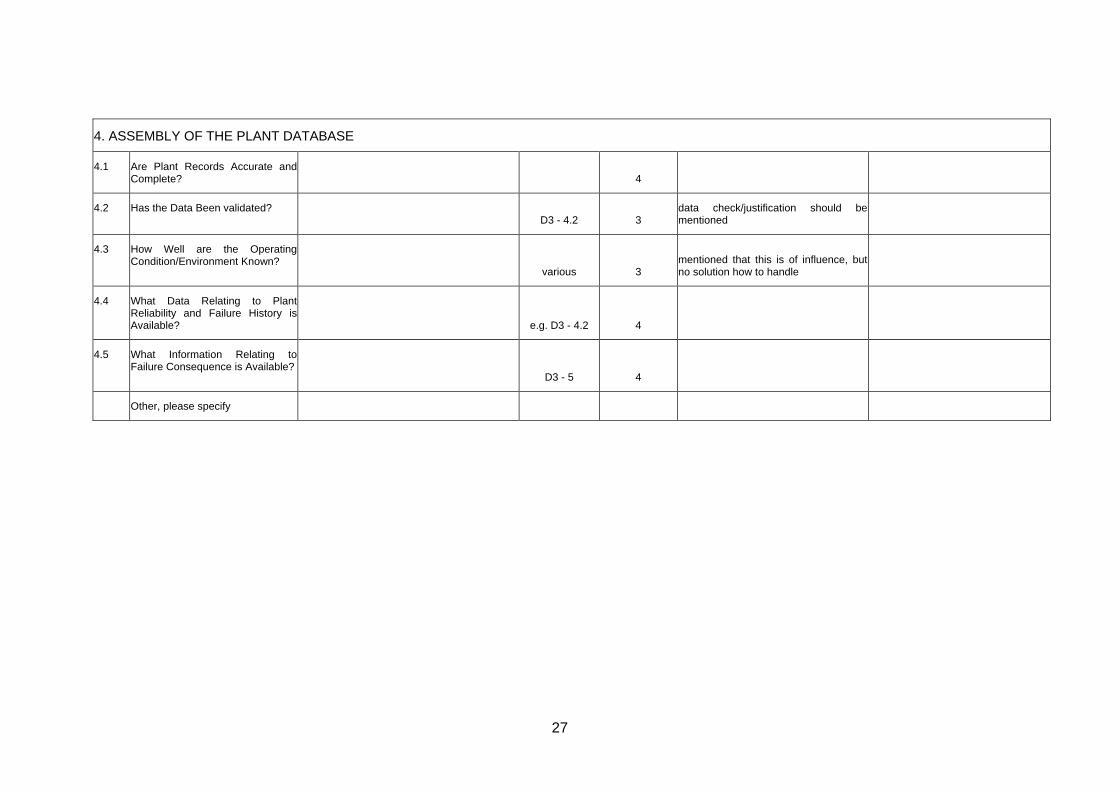
4. ASSEMBLY OF THE PLANT DATABASE
4.1 Are Plant Records Accurate andComplete?
4
4.2 Has the Data Been validated? D3 - 4.2 3
data check/justification should be mentioned
4.3
How Well are the OperatingCondition/Environment Known?
various 3mentioned that this is of influence, but no solution how to handle
4.4 What Data Relating to Plant Reliability and Failure History isAvailable?
e.g. D3 - 4.2 4
4.5 What Information Relating to Failure Consequence is Available?
D3 - 5 4
Other, please specify
27

5. ANALYSIS OF SCENARIOS, DETERIORATION MECHANISMS, RISKS AND UNCERTAINTIES
5.1 Has the Duty Holder Addressed All the Stages of the Risk Analysis?
D3 - 3 4
5.2 What Approach to Risk Analysis isthe Duty Holder Adopting?
" 4
5.3 Identification of Accident Scenarios and failure modes
Have Accident Scenarios Involving Equipment Failure been identified? Are all failure modes reasonably likely to cause functional failures identified at a level of causation that makes it possible to identify appropriate failure management policy? " 4
5.4 Are Deterioration Mechanisms andFailure Modes Identifiedsystematically?
Process for identifying failure modes should be sufficiently wide ranging and systematic to identify failure modes that have happened before, that are currently being prevented by existing maintenance programs and failure modes that have not happened, but considered to be credible in the operating context. The failure modes should be accompanied by corresponding events or processes that are likely to cause them, such as deterioration, human error, etc. " 4
5.5 Has the Likelihood of Failure beenDetermined thoroughly?
Is experienced maintenance personnel used for preparation and/or verification of maintenance & inspection related assumptions in the risk analysis? " 4
Wording Event and Failure Mode is sometimes mixed up
28

5.6 Are the Factors Determining theConsequences of Failureinvestigated?
Are evident failures separated from evident failures? Is there a differentiation between criticality for safety and production/economy?Are the assessments carried out as if no specific task is currently being done to anticipate, prevent or detect the failure?Does the consequence analysis consider: - human exposure to hazards - human factors that can affect the risk (e.g. human machine interaction) - reliability of available safety functions " 4
5.7 What are the Risks of Failure? " 4
5.8 How are the Risks of DifferentItems Ranked and Categorized?
" 4 Risk Aggregation Appendix is necessary
5.9 Is an action plan built using thisranking?
?
5.10 Is the ranking and action planconsistent with operatiexperience? How are these results and assumptions communicated to maintenance personnel?
ng
" 3
what I'm missing is a little bit more related to a qualitative approach which is - in practise - the most common one
5.11 Is the effectiveness of thecorrective actions measured?
D3 - chapter 4 3 Measurement of effectiveness is related to interval not to scope or method
5.12 Is the timeliness of the correctiveactions measured?
" 4 see above
Other, please specify
29

6. DEVELOPMENT OF THE MAINTENANCE AND INSPECTION PLAN WITHIN THE INTEGRITY MANAGEMENT STRATEGY
6.1 What Measures Does the IntegrityManagement Strategy Contain?
This should include functional testing, lubrication, overhaul, etc
3 Focus still on containment equipment
6.2 Does the Written Scheme CoverAll Parts Defined by tRegulations?
he
4
6.3 What Determines the Examinationof Newly Installed Equipment?
3
It should be emphasized that new equipment (without having any in-service inspection) must be treated seperately and that zero -level measurements should be made before putting the components into service
6.4 Does the Timing of the First test orexamination Reflect the Risk?
6.5 What Methods and Factors areused to Set inspection andmaintenance Intervals?
D3 -4 4
6.6 Do Schemes for Inspecting SimilarItems Conform with HSC ACOP?
?
6.7 How are Specific Welds and Sitesfor Examination Identified?
3 not really mentioned or I did not find it
6.8 Are Examination Methods andmaintenance activities Linked toPotential Deterioration?
4 mostly in the appendix
6.9 What Inspection Strategy Appliesto High Failure Consequence Equipment?
4
30

6.10 Completeness of material forpreparation of preventivemaintenance program.
Does it appear from the basic material for preparation of preventive maintenance programme:• which safety-critical failure modes the programme is intended toprevent?• which degradation mechanisms are to be prevented/observed?• when reduced performance/availability brings a system/equipment into a failure modus?• which assumptions are made in the total risk analysis in terms of :- the reliability/testing frequency etc. of the safety systems- the technical conditions of equipment, which in the event of failure could trigger an accident (leaks,etc.)?
4
6.11 Philosophy for condition monitoring critical functions.
Is there a clear philosophy for which critical functions are going to be condition monitored?Is relevant equipment available for planned monitoring? • Is the reliability of the measuring equipment satisfactory in relation to the task(s)? 3
the destinction between trendable and non-trendable deterioration mechansism and their influence to inspection and monitoring should be emphasized in the main documents
6.12 Usage of deadlines for correctivework-orders?
Do all critical corrective work orders receive a deadline? Is non-conformance treatment a requirement and/or should e.g. cause and consequence analyses be performed when a deadline for PM or CM is exceeded? ?
6.13 Are the procedures for mechanicalIntegrity described and of best practice?
D3 -4.3 4
Other, please specify
31

7. ACHIEVING EFFECTIVE, RELIABLE AND SAFE EXAMINATION
7.1 Are the selectedmethods/techniques appropriatefor the detection or prevention ofthe damage mechanismsanticipated?
Will the probability of failure be reduced to an acceptable level?Will the costs for maintenance and inspection be less than the anticipated cost of failure when measured over comparable periods of time? If the tasks are condition-dependent: - is there a defined potential failure? - is there an identifiable P-F interval? - is the task interval less than the shortest likely P-F interval? - In the worst case, is there enogh time for predertemined actions to be taken to control the failure If scheduled task: - is there a defined age at which the probability of failure increases? - does a sufficiently large proportion of failures occur after this time to reduce the likelihood of premature failures to acceptable levels 4
7.2 Are checks carried out to ensurethat the equipment used focondition monitoring, testing or inspection is functioning correct?
r
3 not really mentioned or I did not find it
7.3 Is appropriate training and qualifications required for carryingout inspection and maintenance tasks?
4 qulification and accreditation includes training
32

7.4 Is evidence of NDT capabilityavailable (particularly for non-invasive, long range and acoustic emission inspection techniques)?
4 mostly in the appendix
7.5 Is compatibility with previous inspection results being maintained?
4 mostly in the appendix
7.6 Are inspection datums and co-ordinate systems on tcomponent being maintained for future inspections?
he
3 not really mentioned or I did not find it this is especially in practise a big problem and should be emphasized
7.7 Is the effectiveness of theinspection measured?
4 mostly in the appendix
7.8
Analyses of incidents/accidentsrelated to maintenance.
Do detailed causal analyses exist of incidents/accidents related to maintenance?• Are these used to improve procedures (work orders) for implementing preventive or corrective maintenance?• Are they easily available for personnel who prepare the work orders?- can they be tied to the administration system for maintenance e.g. via a tag no.?Are results from risk analyses etc. used to reinforce requirements relating to a proper impleme tation of maintenance in risky areas and on equipment exposed to risk?
3 should be emphasized in main documents
7.9 Performance of Job Safetyanalyses.
Are there clear requirements as regards when/how/by whom JSAs are to be conducted? • Do the persons who are to conduct the maintenance participate in the Job Safety Analysis? • Do they know the analysis method?• Are there sufficient guidelines to carry out
4
33
the analysis?
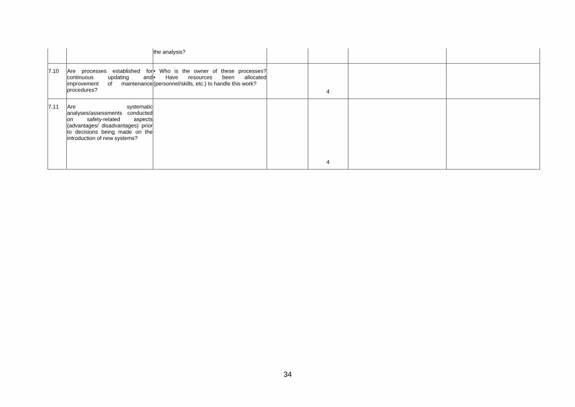
7.10 Are processes established forcontinuous updating andimprovement of maintenanceprocedures?
• Who is the owner of these processes?• Have resources been allocated (personnel/skills, etc.) to handle this work?
4
7.11 Are systematicanalyses/assessments conductedon safety-related aspects (advantages/ disadvantages) prior to decisions being made on the introduction of new systems?
4
34

8. ASSESSMENT OF EXAMINATION RESULTS AND FUTURE FITNESS-FOR-SERVICE
8.1 Are results from examinations andfunctional tests assessed?
8.2 What assessment of fitness-for-service is made?
3 should be emphasized in D3 -4.3
8.3 How has uncertainty in the databeen addressed?
3 not really mentioned or I did not find it
8.4 What measures have been takento address risks from deterioratingequipment?
4
8.5 Are requirements established toinitiate analyses when the controlparameters indicatenonconformance with companyobjectives and requirementsrelated to maintenance?
Which specific criteria/signals should "trigger" an analysis?• Are requirements imposed on causal analyses when preventive maintenance programmes do not prevent safety-critical failure modes from occurring?Which analyses are prepared on a routine basis? Examples:• Analyses of trends of failures on safety-critical equipment and safety systems?• Analyses of an increase in the amount of corrective maintenance? 3
should be emphasized in main document
8.6 Is there a defined set of methods,analysis tools etc. to help makethese analyses?
Are methods for conducting root cause analyses defined?Within which disciplines are such analyses performed? 3 see above
8.7 Is Pre-Startup Safety Review aftermitigation considered and of best industry best practice?
4 could be in more detail
8.8 Are Emergency Responses forequipment under RBI management considered and described?
4 could be in more detail
35

Other, please specify
36

9. FEEDBACK FROM INSPECTION & MAINTENANCE
9.1 What procedures are in place todrive the feedback process?
Rimap Management
Process 4
9.2 Is new knowledge identified withinthe plant database?
? not really mentioned or I did not find it
9.3 Is there evidence of feedbackbeing carried out?
4
9.4 Who is involved in the risk re-assessment
4
9.5 Does good communication existbetween plant operators and the risk assessment team?
4
9.6 Are there clearly expressedrequirements as regards whichsafety-related maintenanceparameters/conditions that shouldbe reported?
Is the reason for requiring that these parameters be reported explained, as well as what will the reports be used for?Are the safety-related company requirements (cf. the chapter on "Objectives and requirements") attended to through requirements relating to reporting, both in terms of scope and level of detail?Are all available sources for safety-related maintenance data used when preparing reports, such as for instance:• Event log, maintenance administration system, non-conformance register, etc.? 4
37

9.7 Are reports required containingrelevant overviews/statistics/trends?
Are reports specified containing overviews/statistics/trends etc. for:• Events (accidents/near misses, etc.) related to /relevant to maintenance?• CM on safety-critical components and equipment for a period?• Outstanding CM on safety-critical failures?• CM on safety systems?• Backlog on preventive maintenance on safety-critical equipment (equipment with safety-critical failure modes)?• Backlog in test-programmes for safety system? • Number of actuations of safety systems?• Number of actuations of safety systems that are temporarily out of function due to maintenance? • Non-conformance reports related to the maintenance function? 4
9.8 Does anyone have responsibilityfor initiating measures for(continuous) improvement of thecontent /quality/ utility value ofreports?
Which measurable, safety-related maintenance parameters should be improved?Are implemented improvement measures followed up through measurement/ control, etc.? Are sufficient resources allocated to prepare reports with the desired scope and quality? 4
9.9 Are methods /processes describedfor implementation of systematicimprovement in the maintenancefunction?
Is the information from analyses, supervision, experience transfer, etc. to systematic follow-up and improvement in accordance with this method? • Are analyses of basic causes of incidents (root cause analysis) used as basis for improvements of registered maintenance problems on different kinds of equipment? 4
Other, please specify
38

10. AUDIT AND REVIEW OF INTEGRITY MANAGEMENT PROCESS
10.1 How often is the managementprocess audited and reviewed?
4
10.2 What certifications or accreditations are required forauditing and to which normation or standard
4
10.3 What aspects of the managementprocess are covered?
4
10.4 Is documentary evidence availableto support each aspect?
4
10.5 How has integrity managementprocess been changed?
4
10.6 Have approved annual and long-term plans been established forinternal an external supervisoryactivities aiming at the maintenance function.
• For whom are the plans committing?How are deviations from the supervisory activity plans handled?
4
10.7 Is there a systematic follow-up offindings from the supervisoryactivities?
Have sufficient resources been allocated for this?
4
10.8 Are the applied supervisorymethods evaluated on acontinuous basis?
Has the company started projects aimed at developing supervision methods?
4
39

10.9 Are there procedures describedand of industry best practice tocapture out-of-boundary operations and report them?
4
10.10 Is a procedure described toreevaluate the RBI study based onthese out-of-boundary operations?
4
Other, please specify
All these issues are mentioned in general, but is deiifcult as user what to do if there is a minor or greater deviation???
40

Appendices 3.2 and 3.3
41

Appendix 3.2
42

APPENDIX 3.2 Assessment by Partner B
Feature / Subject / Aspect Explanation Ref. to Document/
Chapter/ Paragraph
Rating (1-5)
or N/A
Justification (if <=3)
Improvement suggestions
1. REQUIREMENTS FOR RISK BASED MAINTENANCE & INSPECTION
1.1 Have references to published information been made?
The requirements for integrity management and risk based inspection of potentially hazardous plant can be determined by reference to Health and Safety regulations, industry standards and guidelines, and other literature. These can provide valuable information on hazards and control measures as well as covering compliance with Duty Holder’s statutory obligations.
D2.P, p.73; D3.T, p.24 3 More references in D3-documents
43

1.2 Havereasons/drivers for the Risk Based Approach been explained
The main objective of risk based integrity management is to understand and manage the risks of failure of potentially hazardous plant to a level that is acceptable to the organisation and the society within which it operates. Risk based inspection should aim to target finite inspection resources to areas where potential deterioration can lead to high risks. All the objectives of the risk based approach need to be clearly stated at the outset of the process. Duty Holders may wish to consider a wide range of consequences of failure, but as a minimum these should include the Health and Safety of employees and the public, effects on the environment, and implications for their business. It is important that the risks associated with each of these consequences are considered separately and that measures are taken to manage the risks in each case. Duty Holders should ensure that inspection resources are adequate to manage all the risks, and that limited resources do not compromise Health and Safety or environmental risks. All documents 5
This is the main aim of all the RIMAP documents to focus on risk drivers and how to mitigate risk
44

1.3
Is the availability and accuracy of information given, sufficient
The assessment of risk depends on the availability and accuracy of the information relating to the systems and equipment to being assessed. Good information may enable a low risk to be justified, but does not in itself guarantee that the risks are low. Where information is lacking, unavailable, or uncertain, the risk is increased since it cannot be shown that unfavourable circumstances are absent. The type of information required to assess the risk will vary depending on the type of plant, but should be identified at this early stage. The essential data needed to make a risk assessment should be available within the plant database. If it is obvious that the essential data does not exist, action to obtain this information is required or prescriptive inspection procedures should be applied.
Ref D2.P; sec.4.3 4
The need for good data is stressed in many sections. See in particular Preparatory analysis.
1.4 Does the approach reflect theComplexity of the Plant(s)
The rigor of the RBI approach should reflect the complexity of the processes and the installation, as well as the severity of potential hazards and consequences of failure. Where causes and consequences of failure are easily identified as being limited, such as with an isolated boiler, a less rigorous approach may be appropriate. Multiple interacting systems require more detailed analysis of failure modes and effects, while systems whose failure would lead to a major catastrophe may require a full quantitative risk analysis.
D2.P; sec 2.4: Bow tie; sec
2.7; PoF; 4.4: Multilevel 4
D2 does not recommend a dedicatd COF method, but are flexible to the risk. Multilevel approach is recommended.
45

1.5
Has the linkbetween Integrity management, inspection and plant operations, been given and explained
In practice, the integrity management process and inspection are required to integrate with plant operations. Often pressure systems and systems containing hazardous materials have to be depressurised or emptied for inspection, and plant and equipment may also be shut down for reasons of production, process efficiency and general maintenance. There should be no evidence, however, of plant operations compromising the integrity management process or delaying an inspection beyond that which has been justified by a risk assessment.
D2.P: Sec. 3; RIMAP
Management Process 5
This section describes the structure for Maintenance Management. In addition other management issues are mentioned specifically, sec. 3.3
1.6 Have Managementand control of documentation been addressed appropriately
Integrity management and inspection planning require documentation at all the key stages to enable a record, audit and review of the decision making processes. The quality of the information used needs to be verifiable. Duty Holders therefore need to consider at the outset how the traceability and quality of documentation are controlled.
D2.P: Sec 3.3.8; Quality Ass and D2.P:
Data col. 4
Some generic requiurements are set to data collection and validation.
1.7 Are the processes for removal of documentation which is no longer valid addressed?
3 No mentioned specifically in D2.
1.8 Have all applicable rules and regulations been identified
D2.P: Sec 4.2.4; def. Of objective &
Scope 4
Is stressed as a task in the Prep. Work to do so. Should be detailed in each case/for each company
1.9 Is the position to the current rules and
NA As 1.8, need to be locally/company
46

regulations given? wide adapted.
1.10 Are targetedcompany risk levels defined?
Are the requirements relating to safety broken down to an operational level which makes it possible to use these to develop measuring and management parameters related to the maintenance function?Is there a set of clear, safety-related, maintenance objectives?Have management parameters/indicators been developed to follow up these objectives? Are results measured against the overall objectives?Are deviations between objectives and actually achieved results dealt with?
D2.P; Sec. 2: Principles for
risk based decissions. D2.p: 4.2.7;
Risk Acc. Crit 5
A detailed outline of how to set up acceptance criterias.
1.11 Are requirementsspecified foroutstanding work?
Are upper acceptable limits established for the number of outstanding CM's with high priority (for occurred, safety-critical failure modes?) Have similar limits been set for backlog of PM's?Have limits been set at system/function level?Do requirements exist for the frequency of monitoring, reporting and analysis of outstanding CM's (weekly, monthly, over time (trends)? Are there established guidelines in terms of measures if the acceptable limits are exceeded? (Example of measures: Reduced activity level, extra manning, start-up of maintenance campaign, etc.) WP4 4
The concept is called Risk Based Work Selection and covered in D4.1.
47

1.12 Are assumptionsand results used to conduct riskanalyses considered?
Are assumptions and results used to conduct risk analyses as basis for formulating requirements related to function/condition of· Safety systems and· Other systems critical to safety and equipment?
D2.P: Sec. 2.2; safety s.;
D3.x 5
Details covered in D3 and WP4/Chemical.
1.13 Is Leadership and Administration well described and of industry bestpractice?
Leadership is considered crucial in implementing and sustaining an effective Process Safety Management effort.
D2.P: Sec. 3; RIMAP
Management Process 4
A number of leadership issues are described in the text, incl PSM
1.14
Does organization at the corporate or local level have a general policy statement reflecting management’s commitment to Process Safety Management, and emphasizing safety and loss control issues?
the
NA NA A plant/local issuel.
1.15 Is the general policy statement: a. Contained in manuals? b. Posted in various locations? c. Included as a part of all rule booklets? d. Referred to in all major training programs? e. Used in other ways? (Describe)
NA NA
48

1.16 Is the importance of Process SafetyInformation well described and of industry best practice?
NA NA
1.17 Is the importance of Process Hazard Analysis well described and of industry best practice?
NA NA
1.18
Is the role Management of Change outlined well and meets industry best practice?
D2.P; sec 3.3.1; Mng of
change 4
Mentioned specifically, but not detailed
1.19 Is the importance of Operating Procedures well described and of industry best practice?
D2.P: sec. 4.3.4. 3
Part of prep.analysis
Other, please specify
49

2 DEFINING THE SYSTEMS AND EQUIPMENT REQUIRING INTEGRITY MANAGEMENT
2.1 Are the Systems Requiring Integrity management Clearly Defined
2.2 Are the Boundaries of Every System Clearly Defined
2.3 Have all Equipment and Factors Relevant to the Risk been included?
2.4 Is a time scale associated with targets?
2.5 Has the operating envelope and all functions of every system been identified?
The operating envelope includes: limits of systems, including phases of system life, intended use (both correct use and foreseeable maltreatment or misuse), anticipated characteristics of users. Are expected performance levels specified?
Other, please specify
50

3. SPECIFYING THE RBIM MANAGEMENT TEAM AND RESPONSIBILITIES
3.1 Who is Managing the Integrity Management Process?
D2.F, sec, 6; D2.P,
sec 3.2, 3.3.7, 3.3.8 NA
General disipline resources defined in a multidisiplinary team. Rating is difficult as this in generic requirements
3.2 Who Are the Members of the Team?
D2.P, sec 3.1 NA
3.3 Does the Team have Knowledge and Experience in the Key Areas?
D2.P, sec 3.1 D2.R, sec
2.1.1. NA
3.4 Do the Team Members have Adequate Qualifications and Competence?
D2.P, sec 3.3.7 NA
3.5 How Does the Team Report Into the Safety Management System?
???
3.6 Does the Team have Wider Industry Knowledge?
D2.R,sec
3.3.7 NA
3.7 How is the “Competent Person” Integrated in the Team?
NA
"Competence Person"; A special issue in some countries to have a competence person. Not a PED requirement.
3.8 How Does the Team Record Meetings and Decisions?
A project management issue. Ref. to documentation;
51

3.9 Is Access to Staff, Experts and other Resources Adequate?
NA
A plant issue. Requirement defines this.
3.10 What Are the Team’s Terms of Reference
NA See qualifications
3.11 Are the Training needs described for the roles involved in RBI management?
D2.P, 3.1 4
Other, please specify
52

4. ASSEMBLY OF THE PLANT DATABASE
4.1
Are Plant Records Accurate and Complete?
D2.P,
4.3 NA General requirements set in the D2.P; sec. 4.3
4.2 Has the Data Been validated?
D2.P, 4.3 NA
4.3 How Well are the Operating Condition/Environment Known?
D2.P, 4.3 na
4.4 What Data Relating to Plant Reliability and Failure History is Available?
D2.P, 4.3 na
4.5 What Information Relating to Failure Consequence is Available?
D2.P, 4.3 na
Other, please specify
53

5. ANALYSIS OF SCENARIOS, DETERIORATION MECHANISMS, RISKS AND UNCERTAINTIES
5.1 Has the Duty Holder Addressed All the Stages of the Risk Analysis?
D2.P, 4; Working
Procedure NAGeneral requirements set in the D2.P; sec. 4.4
5.2 What Approach to Risk Analysis is the Duty Holder Adopting?
D2.P, 4.2.7 NA
5.3 Identification of Accident Scenarios and failure modes
Have Accident Scenarios Involving Equipment Failure been identified? Are all failure modes reasonably likely to cause functional failures identified at a level of causation that makes it possible to identify appropriate failure management policy? D2.P, 4.4 Details in D3
5.4 Are Deterioration Mechanisms andFailure ModesIdentified systematically?
Process for identifying failure modes should be sufficiently wide ranging and systematic to identify failure modes that have happened before, that are currently being prevented by existing maintenance programs and failure modes that have not happened, but considered to be credible in the operating context. The failure modes should be accompanied by corresponding events or processes that are likely to cause them, such as deterioration, human error, etc. D2.P, 4.4 Details in D3
5.5 Has the Likelihood of Failure beenDetermined thoroughly?
Is experienced maintenance personnel used for preparation and/or verification of maintenance & inspection related assumptions in the risk analysis? D2.P, 4.4 Details in D3 4.3
54
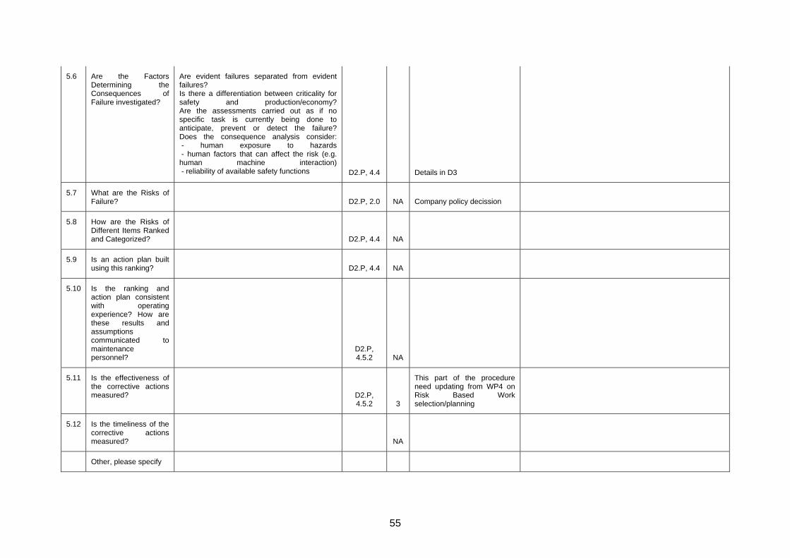
5.6 Are the Factors Determining theConsequences ofFailure investigated?
Are evident failures separated from evident failures? Is there a differentiation between criticality for safety and production/economy?Are the assessments carried out as if no specific task is currently being done to anticipate, prevent or detect the failure?Does the consequence analysis consider: - human exposure to hazards - human factors that can affect the risk (e.g. human machine interaction) - reliability of available safety functions D2.P, 4.4 Details in D3
5.7 What are the Risks of Failure?
D2.P, 2.0 NA Company policy decission
5.8 How are the Risks of Different Items Ranked and Categorized?
D2.P, 4.4 NA
5.9 Is an action plan built using this ranking?
D2.P, 4.4 NA
5.10 Is the ranking and action plan consistent with operating experience? How are these results and assumptions communicated to maintenance personnel?
D2.P, 4.5.2 NA
5.11 Is the effectiveness of the corrective actions measured?
D2.P, 4.5.2 3
This part of the procedure need updating from WP4 on Risk Based Work selection/planning
5.12 Is the timeliness of the corrective actions measured?
NA
Other, please specify
55

6. DEVELOPMENT OF THE MAINTENANCE AND INSPECTION PLAN WITHIN THE INTEGRITY MANAGEMENT STRATEGY
6.1 What Measures Does the IntegrityManagement Strategy Contain?
This should include functional testing, lubrication, overhaul, etc
NA
6.2
Does the Written Scheme Cover All Parts Defined by the Regulations?
D2.P, 4.2.5 4 Yes
6.3 What Determines the Examination of Newly Installed Equipment?
3 Not directly mentoined
6.4 Does the Timing of the First test or examination Reflect the Risk?
3 Not directly mentoined
6.5 What Methods and Factors are used to Set inspection and maintenance Intervals?
D2.P,
2.1 &4.4 4 Detaails given in D3.
6.6 Do Schemes for Inspecting SimilarItems Conform with HSC ACOP?
???
6.7 How are Specific Welds and Sites for Examination Identified?
NA Detailed RBI analysis.
6.8
Are Examination Methods and maintenance activities Linked to Potential Deterioration?
D2.P 4The basis for all M&I is the degradtion
56

6.9
What Inspection Strategy Applies to High Failure Consequence Equipment?
D2.P; 2.1 & 4.2.7 3
D2 defines different measures to use for risk decission. It it up to the company to define its limits to high and low consequence failures.
6.10
Completeness of material for preparation of preventivemaintenance program.
Does it appear from the basic material for preparation of preventive maintenance programme:• which safety-critical failure modes the programme is intended to prevent?• which degradation mechanisms are to be prevented/observed?• when reduced performance/availability brings a system/equipment into a failure modus?• which assumptions are made in the total risk analysis in terms of :- the reliability/testing frequency etc. of the safety systems- the technical conditions of equipment, which in the event of failure could trigger an accident (leaks,etc.)?
D2.P; 4.3,
4.5.2.13 3
Part of the specific analysis. D2 gives guidance on what to produce, but could be more specific on required documentation.
6.11 Philosophy for condition monitoring critical functions.
Is there a clear philosophy for which critical functions are going to be condition monitored?Is relevant equipment available for planned monitoring? • Is the reliability of the measuring equipment satisfactory in relation to the task(s)?
Part of the analysis, not details for degradation. See D4.x (Workbooks) for details.
6.12 Usage of deadlines for corrective work-orders?
Do all critical corrective work orders receive a deadline? Is non-conformance treatment a requirement and/or should e.g. cause and consequence analyses be performed when a deadline for PM or CM is exceeded? 4
Risk based work selection, D4.
6.13 Are the procedures for mechanical Integrity described and of best practice?
4
D2, D3, D4 is considered best practice.
Other, please specify
57

7. ACHIEVING EFFECTIVE, RELIABLE AND SAFE EXAMINATION
7.1 Are the selected methods/techniques appropriate for the detection or prevention of the damage mechanisms anticipated?
Will the probability of failure be reduced to an acceptable level?Will the costs for maintenance and inspection be less than the anticipated cost of failure when measured over comparable periods of time? If the tasks are condition-dependent: - is there a defined potential failure? - is there an identifiable P-F interval? - is the task interval less than the shortest likely P-F interval? - In the worst case, is there enogh time for predertemined actions to be taken to control the failure If scheduled task: - is there a defined age at which the probability of failure increases? - does a sufficiently large proportion of failures occur after this time to reduce the likelihood of premature failures to acceptable levels 4 Part of the analysis.
7.2 Are checks carried out to ensure that the equipment used for condition monitoring, testing or inspection is functioning correct?
3
Not mentioned specifically. Should be highlightet for cases where the risk is entierly dependent on the functioning of the CM equipment.
7.3 Is appropriate training and qualifications required for carrying out inspection and maintenance tasks?
D2.P; 3.1 4
58

7.4 Is evidence of NDT capability available (particularly for non-invasive, long range and acoustic emission inspection techniques)?
NA Specific to workbooks.
7.5
Is compatibility with previous inspection results being maintained?
D2.P; 4.3.5 4
Part of Preparatory analysis.
7.6 Are inspection datumsand co-ordinatesystems on the component being maintained for future inspections?
???
7.7 Is the effectiveness of the inspection measured?
D2.P; 4.6.4 4
7.8 Analyses of incidents/accidents related tomaintenance.
Do detailed causal analyses exist of incidents/accidents related to maintenance?• Are these used to improve procedures (work orders) for implementing preventive or corrective maintenance?• Are they easily available for personnel who prepare the work orders?- can they be tied to the administration system for maintenance e.g. via a tag no.?Are results from risk analyses etc. used to reinforce requirements relating to a proper impleme tation of maintenance in risky areas and on equipment exposed to risk?
NA Root cause analysis not part of D2.
59

7.9 Performance of Job Safety analyses.
Are there clear requirements as regards when/how/by whom JSAs are to be conducted? • Do the persons who are to conduct the maintenance participate in the Job Safety Analysis? • Do they know the analysis method?• Are there sufficient guidelines to carry out the analysis? D2.P;
4.5.3 3 Could be improved.
7.10 Are processes established forcontinuous updating and improvement of maintenance procedures?
• Who is the owner of these processes?• Have resources been allocated (personnel/skills, etc.) to handle this work?
D2.F 5 D2.F stresses this aspect.
7.11 Are systematic analyses/assessments conducted on safety-related aspects (advantages/ disadvantages) prior to decisions being made on the introduction of new systems?
NA
60
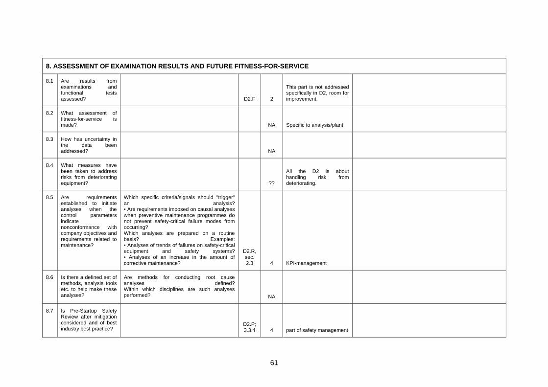
8. ASSESSMENT OF EXAMINATION RESULTS AND FUTURE FITNESS-FOR-SERVICE
8.1
Are results from examinations and functional tests assessed?
D2.F 2
This part is not addressed specifically in D2, room for improvement.
8.2 What assessment of fitness-for-service is made?
NA Specific to analysis/plant
8.3 How has uncertainty in the data been addressed?
NA
8.4 What measures have been taken to address risks from deteriorating equipment?
??
All the D2 is about handling risk from deteriorating.
8.5
Are requirements established to initiate analyses when the control parametersindicate nonconformance with company objectives and requirements related to maintenance?
Which specific criteria/signals should "trigger" an analysis?• Are requirements imposed on causal analyses when preventive maintenance programmes do not prevent safety-critical failure modes from occurring? Which analyses are prepared on a routine basis? Examples:• Analyses of trends of failures on safety-critical equipment and safety systems?• Analyses of an increase in the amount of corrective maintenance?
D2.R, sec. 2.3 4 KPI-management
8.6 Is there a defined set of methods, analysis tools etc. to help make these analyses?
Are methods for conducting root cause analyses defined?Within which disciplines are such analyses performed? NA
8.7 Is Pre-Startup Safety Review after mitigation considered and of best industry best practice?
D2.P; 3.3.4 4 part of safety management
61

8.8 Are Emergency Responses for equipment under RBI management considered and described?
D2.P; 3.3.5 4 part of safety management
Other, please specify
62
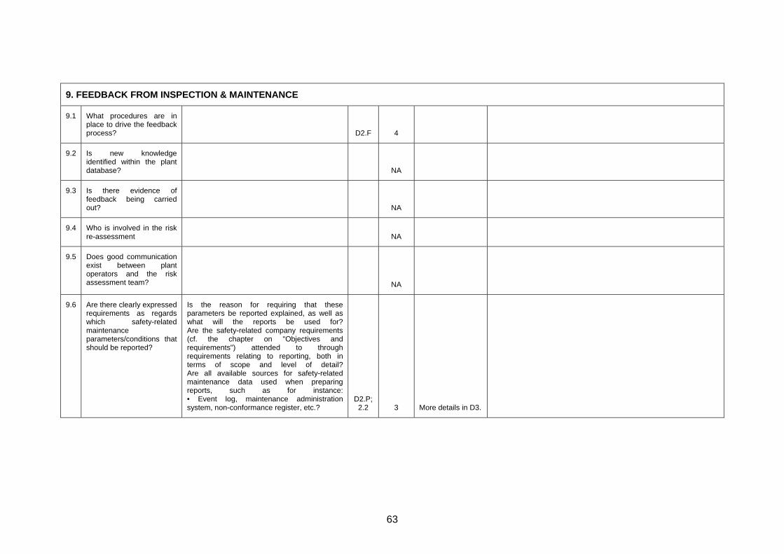
9. FEEDBACK FROM INSPECTION & MAINTENANCE
9.1 What procedures are in place to drive the feedback process?
D2.F 4
9.2 Is new knowledge identified within the plant database?
NA
9.3 Is there evidence of feedback being carried out?
NA
9.4 Who is involved in the risk re-assessment
NA
9.5 Does good communication exist between plant operators and the risk assessment team?
NA
9.6 Are there clearly expressed requirements as regards which safety-relatedmaintenance parameters/conditions that should be reported?
Is the reason for requiring that these parameters be reported explained, as well as what will the reports be used for?Are the safety-related company requirements (cf. the chapter on "Objectives and requirements") attended to through requirements relating to reporting, both in terms of scope and level of detail?Are all available sources for safety-related maintenance data used when preparing reports, such as for instance:• Event log, maintenance administration system, non-conformance register, etc.?
D2.P; 2.2 3 More details in D3.
63
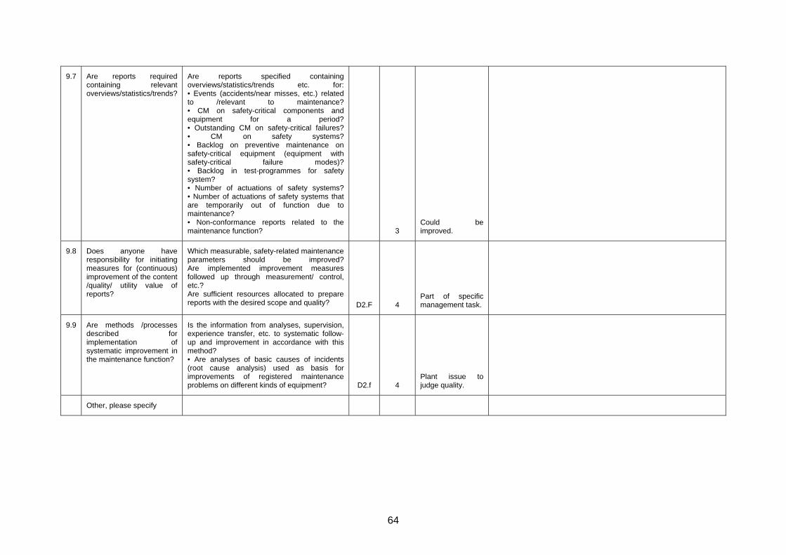
9.7 Are reports required containing relevantoverviews/statistics/trends?
Are reports specified containing overviews/statistics/trends etc. for:• Events (accidents/near misses, etc.) related to /relevant to maintenance?• CM on safety-critical components and equipment for a period?• Outstanding CM on safety-critical failures?• CM on safety systems?• Backlog on preventive maintenance on safety-critical equipment (equipment with safety-critical failure modes)?• Backlog in test-programmes for safety system? • Number of actuations of safety systems?• Number of actuations of safety systems that are temporarily out of function due to maintenance? • Non-conformance reports related to the maintenance function? 3
Could be improved.
9.8 Does anyone have responsibility for initiating measures for (continuous) improvement of the content /quality/ utility value of reports?
Which measurable, safety-related maintenance parameters should be improved?Are implemented improvement measures followed up through measurement/ control, etc.? Are sufficient resources allocated to prepare reports with the desired scope and quality? D2.F 4
Part of specific management task.
9.9 Are methods /processes described forimplementation ofsystematic improvement in the maintenance function?
Is the information from analyses, supervision, experience transfer, etc. to systematic follow-up and improvement in accordance with this method? • Are analyses of basic causes of incidents (root cause analysis) used as basis for improvements of registered maintenance problems on different kinds of equipment? D2.f 4
Plant issue to judge quality.
Other, please specify
64
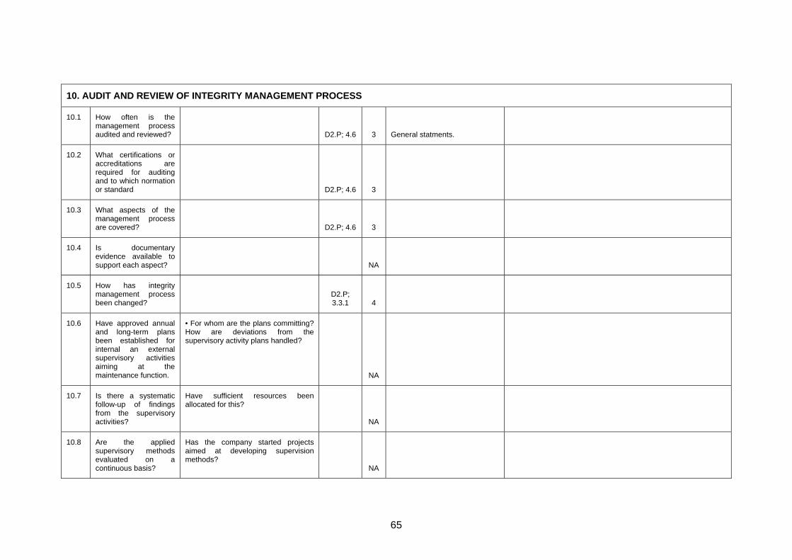
10. AUDIT AND REVIEW OF INTEGRITY MANAGEMENT PROCESS
10.1 How often is the management process audited and reviewed?
D2.P; 4.6 3 General statments.
10.2 What certifications or accreditations are required for auditing and to which normation or standard
D2.P; 4.6 3
10.3 What aspects of the management process are covered?
D2.P; 4.6 3
10.4 Is documentary evidence available to support each aspect?
NA
10.5 How has integrity management process been changed?
D2.P; 3.3.1 4
10.6 Have approved annualand long-term plans been established for internal an external supervisory activities aiming at the maintenance function.
• For whom are the plans committing?How are deviations from the supervisory activity plans handled?
NA
10.7 Is there a systematic follow-up of findings from the supervisory activities?
Have sufficient resources been allocated for this?
NA
10.8 Are the applied supervisory methods evaluated on a continuous basis?
Has the company started projects aimed at developing supervision methods?
NA
65

10.9 Are there procedures described and of industry best practice to capture out-of-boundary operations and report them?
D2.P; 4.3.4 4
10.10 Is a procedure described to reevaluate the RBI study based on these out-of-boundary operations?
D2.P; 4.3.4 4
66

Appendix 3.3
67

APPENDIX 3.3 Assessment by Partner C
Feature / Subject / Aspect Explanation Ref. to Document/ Chapter/ Paragraph Rating (1-5) or N/A
Justification (if <=3) Improvement suggestions
1. REQUIREMENTS FOR RISK BASED MAINTENANCE & INSPECTION
1.1 Have references topublished informationbeen made?
The requirements for integrity management and risk based inspection of potentially hazardous plant can be determined by reference to Health and Safety regulations, industry standards and guidelines, and other literature. These can provide valuable information on hazards and control measures as well as covering compliance with Duty Holder’s statutory obligations.
N/A Given in RIMAP D2 Documents. Out of scope for D3.1.
1.2 Have reasons/driversfor the Risk BasedApproach beenexplained
The main objective of risk based integrity management is to understand and manage the risks of failure of potentially hazardous plant to a level that is acceptable to the organisation and the society within which it operates. Risk based inspection should aim to target finite inspection resources to areas where potential deterioration can lead to high risks. All the objectives of the risk based approach need to be clearly stated at the outset of the process. Duty Holders may wish to consider a wide range of consequences of failure, but as a minimum these should include the Health and Safety of employees and the public, effects on the environment, and implications for their business. It is important that the risks associated with each of these consequences are considered separately and that measures are taken to manage the risks in each case. Duty Holders should ensure that inspection resources are adequate to manage all the risks, and that limited resources do not compromise Health and Safety or environmental
N/A
68

1.3 Is the availability andaccuracy of information given, sufficient
The assessment of risk depends on the availability and accuracy of the information relating to the systems and equipment to being assessed. Good information may enable a low risk to be justified, but does not in itself guarantee that the risks are low. Where information is lacking, unavailable, or uncertain, the risk is increased since it cannot be shown that unfavourable circumstances are absent. The type of information required to assess the risk will vary depending on the type of plant, but should be identified at this early stage. The essential data needed to make a risk assessment should be available within the plant database. If it is obvious that the essential data does not exist, action to obtain this information is required or prescriptive inspection procedures should be applied.
N/A
1.4 Does the approachreflect the Complexityof the Plant(s)
The rigor of the RBI approach should reflect the complexity of the processes and the installation, as well as the severity of potential hazards and consequences of failure. Where causes and consequences of failure are easily identified as being limited, such as with an isolated boiler, a less rigorous approach may be appropriate. Multiple interacting systems require more detailed analysis of failure modes and effects, while systems whose failure would lead to a major catastrophe may require a full quantitative risk analysis.
N/A
1.5 Has the link betweenIntegrity management,inspection and plantoperations, been given and explained
In practice, the integrity management process and inspection are required to integrate with plant operations. Often pressure systems and systems containing hazardous materials have to be depressurised or emptied for inspection, and plant and equipment may also be shut down for reasons of production, process efficiency and general maintenance. There should be no evidence, however, of plant operations compromising the integrity management process or delaying an inspection beyond that which has been justified by a risk assessment.
N/A
1.6 Have Management and control ofdocumentation beenaddressed appropriately
Integrity management and inspection planning require documentation at all the key stages to enable a record, audit and review of the decision making processes. The quality of the information used needs to be verifiable. Duty Holders therefore need to consider at the outset how the traceability and quality of documentation are controlled.
N/A
69

1.7 Are the processes for removal of documentation which is no longer valid addressed?
N/A
1.8 Have all applicable rules and regulations been identified
N/A
1.9 Is the position to the current rules and regulations given?
N/A
1.10 Are targeted company risk levelsdefined?
Are the requirements relating to safety broken down to an operational level which makes it possible to use these to develop measuring and management parameters related to the maintenance function?
Is there a set of clear, safety-related, maintenance objectives?
Have management parameters/indicators been developed to follow up these objectives?
Are results measured against the overall objectives?
Are deviations between objectives and actually achieved results dealt with?
N/A
1.11 Are requirements specified foroutstanding work?
Are upper acceptable limits established for the number of outstanding CM's with high priority (for occurred, safety-critical failure modes?)
Have similar limits been set for backlog of PM's?
Have limits been set at system/function level?
Do requirements exist for the frequency of monitoring, reporting and analysis of outstanding CM's (weekly, monthly, over time (trends)?
N/A
70

Are there established guidelines in terms of measures if the acceptable limits are exceeded? (Example of measures: Reduced activity level, extra manning, start-up of maintenance campaign, etc.)
1.12 Are assumptions and results used to conduct risk analyses considered?
Are assumptions and results used to conduct risk analyses as basis for formulating requirements related to function/condition of
· Safety systems and
· Other systems critical to safety and equipment?
N/A
1.13 Is Leadership and Administration well described and of industry bestpractice?
Leadership is considered crucial in implementing and sustaining an effective Process Safety Management effort.
N/A
1.14 Does the organization at the corporate or local level have a general policy statement reflecting management’s commitment to Process Safety Management, and emphasizing safety and loss control issues?
N/A
1.15 Is the general policy statement:
a. Contained in manuals?
b. Posted in various locations?
N/A
71
c. Included as a part of all rule booklets?
d. Referred to in all major training programs?
e. Used in other ways? (Describe)
N/A
N/A
N/A
N/A
N/A
1.16 Is the importance of Process Safety Information well described and of industry best practice?
N/A
1.17 Is the importance of Process Hazard Analysis well described and of industry best practice?
N/A
1.18 Is the role Management of Change outlined well and meets industry best practice?
N/A
1.19 Is the importance of Operating Procedures well described and of industry best practice?
N/A
Other, please specify
72

2 DEFINING THE SYSTEMS AND EQUIPMENT REQUIRING INTEGRITY MANAGEMENT
2.1 Are the Systems Requiring Integrity management Clearly Defined sec. 2. 4 Systems not clearly defined but hierarchical and functional breakdown is explained and references to other documents are availale.
2.2 Are the Boundaries of Every System Clearly Defined App. A 4 Examples of boundary definition given
2.3 Have all Equipment and Factors Relevant to the Risk been included? sec. 3 + appendice
s
4
2.4 Is a time scale associated with targets?
sec. 4, app. B, app. C, app. E
4
2.5 Has the operatingenvelope and allfunctions of everysystem been identified?
The operating envelope includes: limits of systems, including phases of system life, intended use (both correct use and foreseeable maltreatment or misuse), anticipated characteristics of users. Are expected performance levels specified?
sec. 2 + appendice
s
3 Not all functions of every system identified but function and subfunction breakdown described and references given.
Other, please specify
73

3. SPECIFYING THE RBIM MANAGEMENT TEAM AND RESPONSIBILITIES
3.1 Who is Managing the Integrity Management Process? N/A Out of scope for this document, given elswhere in RIMAP documentation.
3.2 Who Are the Members of the Team?
N/A
3.3 Does the Team have Knowledge and Experience in the Key Areas? N/A
3.4 Do the Team Members have Adequate Qualifications and Competence?
N/A
3.5 How Does the Team Report Into the Safety Management System? N/A
3.6 Does the Team have Wider Industry Knowledge?
N/A
3.7 How is the “Competent Person” Integrated in the Team? N/A
3.8 How Does the Team Record Meetings and Decisions? N/A
3.9 Is Access to Staff, Experts and other Resources Adequate? N/A
3.10 What Are the Team’s Terms of Reference
N/A
3.11 Are the Training needs described for the roles involved in RBI management?
N/A
74

Other, please specify
75

4. ASSEMBLY OF THE PLANT DATABASE
4.1 Are Plant Records Accurate and Complete? N/A Out of scope for this document, given elswhere in RIMAP documentation (general requirements given in D2 RIMAP procedure)
4.2 Has the Data Been validated?
N/A Out of scope for this document, given elswhere in RIMAP documentation (general requirements given in D2 RIMAP procedure, Data validation)
4.3 How Well are the Operating Condition/Environment Known? N/A
4.4 What Data Relating to Plant Reliability and Failure History is Available?
sec. 4, + app. C
4
4.5 What Information Relating to Failure Consequence is Available? sec. 5 + app. B
4
Other, please specify
76

5. ANALYSIS OF SCENARIOS, DETERIORATION MECHANISMS, RISKS AND UNCERTAINTIES
5.1 Has the Duty Holder Addressed All the Stages of the Risk Analysis? sec. 2 through 7
5
5.2 What Approach to Risk Analysis is the Duty Holder Adopting? N/A
5.3 Identification ofAccident Scenarios and failure modes
Have Accident Scenarios InvolvingEquipment Failure been identified? Are all failure modes reasonably likely to cause functional failures identified at a level of causation that makes it possible to identify appropriate failure management policy?
sec. 3, 4, 5 +
appendices
5
5.4 Are DeteriorationMechanisms andFailure ModesIdentified systematically?
Process for identifying failure modes should be sufficiently wide ranging and systematic to identify failure modes that have happened before, that are currently being prevented by existing maintenance programs and failure modes that have not happened, but considered to be credible in the operating context. The failure modes should be accompanied by corresponding events or processes that are likely to cause them, such as deterioration, human error, etc.
sec 3, 4 + app. A
5
5.5 Has the Likelihood ofFailure beenDetermined thoroughly?
Is experienced maintenance personnel used for preparation and/or verification of maintenance & inspection related assumptions in the risk analysis?
sec. 4 + app. C
5
77

5.6 Are the FactorsDetermining theConsequences ofFailure investigated?
Are evident failures separated from evident failures?
Is there a differentiation between criticality for safety and production/economy?
Are the assessments carried out as if no specific task is currently being done to anticipate, prevent or detect the failure?
Does the consequence analysis consider:
- human exposure to hazards
- human factors that can affect the risk (e.g. human machine interaction)
- reliability of available safety functions
sec. 5 + app. B
5
5.7 What are the Risks of Failure?
sec. 3, 6 4
5.8 How are the Risks of Different Items Ranked and Categorized? sec. 6 + app. E, app. G
4
5.9 Is an action plan built using this ranking?
sec 7. 5
5.10 Is the ranking and action plan consistent with operating experience? How are these results and assumptions communicated to maintenance personnel?
app. E 4
5.11 Is the effectiveness of the corrective actions measured? app. D 5
78

5.12 Is the timeliness of the corrective actions measured? sec. 7 + app. E, app. F
4
Other, please specify
79

6. DEVELOPMENT OF THE MAINTENANCE AND INSPECTION PLAN WITHIN THE INTEGRITY MANAGEMENT STRATEGY
6.1 What Measures Doesthe IntegrityManagement StrategyContain?
This should include functional testing, lubrication, overhaul, etc
N/A
6.2 Does the Written Scheme Cover All Parts Defined by the Regulations? N/A
6.3 What Determines the Examination of Newly Installed Equipment? 1 Not mentioned.
6.4 Does the Timing of the First test or examination Reflect the Risk? 1 Not mentioned.
6.5 What Methods and Factors are used to Set inspection and maintenance Intervals?
4
6.6 Do Schemes for Inspecting Similar Items Conform with HSC ACOP? N/A
6.7 How are Specific Welds and Sites for Examination Identified? N/A Out of scope of D3 document. Detailed analyisis.
6.8 Are Examination Methods and maintenance activities Linked to Potential Deterioration?
N/A Given elswhere in RIMAP documentation (D2 RIMAP Procedure)
6.9 What Inspection Strategy Applies to High Failure Consequence Equipment?
app. A4 4
80

6.10 Completeness ofmaterial for preparation of preventivemaintenance program.
Does it appear from the basic material for preparation of preventive maintenance programme:
• which safety-critical failure modes the programme is intended to prevent?
• which degradation mechanisms are to be prevented/observed?
• when reduced performance/availability brings a system/equipment into a failure modus?
• which assumptions are made in the total risk analysis in terms of :
- the reliability/testing frequency etc. of the safety systems
- the technical conditions of equipment, which in the event of failure could trigger an accident (leaks,etc.)?
sec. 7 3 Mentioned but not enough details given
6.11 Philosophy for condition monitoring criticalfunctions.
Is there a clear philosophy for which critical functions are going to be condition monitored?
Is relevant equipment available for planned monitoring?
• Is the reliability of the measuring equipment satisfactory in relation to the task(s)?
1 Not mentioned.
6.12 Usage of deadlines for corrective work-orders?
Do all critical corrective work orders receive a deadline? Is non-conformance treatment a requirement and/or should e.g. cause and consequence analyses be performed when a deadline for PM or CM is exceeded?
1 Not mentioned.
81

6.13 Are the procedures for mechanical Integrity described and of best practice?
1 Not mentioned.
Other, please specify
82

7. ACHIEVING EFFECTIVE, RELIABLE AND SAFE EXAMINATION
7.1 Are the selectedmethods/techniques appropriate for thedetection or prevention of the damagemechanisms anticipated?
Will the probability of failure be reduced to an acceptable level?
Will the costs for maintenance and inspection be less than the anticipated cost of failure when measured over comparable periods of time?
If the tasks are condition-dependent:
- is there a defined potential failure?
- is there an identifiable P-F interval?
- is the task interval less than the shortest likely P-F interval?
- In the worst case, is there enogh time for predertemined actions to be taken to control the failure
If scheduled task:
- is there a defined age at which the probability of failure increases?
- does a sufficiently large proportion of failures occur after this time to reduce the likelihood of premature failures to acceptable levels
app. A 5
83

7.2 Are checks carried out to ensure that the equipment used for condition monitoring, testing or inspection is functioning correct?
app. D2.2, app. D2.3
4
7.3 Is appropriate training and qualifications required for carrying out inspection and maintenance tasks?
N/A
7.4 Is evidence of NDT capability available (particularly for non-invasive, long range and acoustic emission inspection techniques)?
app. D 4
7.5 Is compatibility with previous inspection results being maintained? N/A
7.6 Are inspection datums and co-ordinate systems on the component being maintained for future inspections?
N/A
7.7 Is the effectiveness of the inspection measured?
app. D 4
84

7.8 Analyses ofincidents/accidents related to maintenance.
Do detailed causal analyses exist of incidents/accidents related to maintenance?
• Are these used to improve procedures (work orders) for implementing preventive or corrective maintenance?
• Are they easily available for personnel who prepare the work orders?
- can they be tied to the administration system for maintenance e.g. via a tag no.?
Are results from risk analyses etc. used to reinforce requirements relating to a proper impleme tation of maintenance in risky areas and on equipment exposed to risk?
sec. 4, app. app.
C
4
7.9 Performance of JobSafety analyses.
Are there clear requirements as regards when/how/by whom JSAs are to be conducted?
• Do the persons who are to conduct the maintenance participate in the Job Safety Analysis?
• Do they know the analysis method?
• Are there sufficient guidelines to carry out the analysis?
N/A Out of scope of D3 document.
7.10 Are processesestablished for continuous updating and improvement ofmaintenance procedures?
• Who is the owner of these processes?
• Have resources been allocated (personnel/skills, etc.) to handle this work?
N/A Out of scope of D3 document.
85

7.11 Are systematic analyses/assessments conducted on safety-related aspects (advantages/ disadvantages) prior to decisions being made on the introduction of new systems?
N/A
86

8. ASSESSMENT OF EXAMINATION RESULTS AND FUTURE FITNESS-FOR-SERVICE
8.1 Are results from examinations and functional tests assessed?
8.2 What assessment of fitness-for-service is made?
8.3 How has uncertainty in the data been addressed?
8.4 What measures have been taken to address risks from deteriorating equipment?
8.5 Are requirementsestablished to initiateanalyses when the control parameters indicate nonconformance withcompany objectivesand requirements related to maintenance?
Which specific criteria/signals should "trigger" an analysis?
• Are requirements imposed on causal analyses when preventive maintenance programmes do not prevent safety-critical failure modes from occurring?
Which analyses are prepared on a routine basis? Examples:
• Analyses of trends of failures on safety-critical equipment and safety systems?
• Analyses of an increase in the amount of corrective maintenance?
app. E, E3 4
8.6 Is there a defined set of methods, analysis tools etc. to help make these analyses?
Are methods for conducting root cause analyses defined?
Within which disciplines are such analyses performed?
N/A
87

8.7 Is Pre-Startup Safety Review after mitigation considered and of best industry best practice?
N/A
8.8 Are Emergency Responses for equipment under RBI management considered and described?
N/A
Other, please specify
88

9. FEEDBACK FROM INSPECTION & MAINTENANCE
9.1 What procedures are in place to drive the feedback process? app, F, F5 4
9.2 Is new knowledge identified within the plant database? app, F, F5 4
9.3 Is there evidence of feedback being carried out? app, F, F5 4
9.4 Who is involved in the risk re-assessment N/A
9.5 Does good communication exist between plant operators and the risk assessment team?
N/A
9.6 Are there clearly expressedrequirements as regards whichsafety-related maintenanceparameters/conditions that should be reported?
Is the reason for requiring that these parameters be reported explained, as well as what will the reports be used for?
Are the safety-related company requirements (cf. the chapter on "Objectives and requirements") attended to through requirements relating to reporting, both in terms of scope and level of detail?
Are all available sources for safety-related maintenance data used when preparing reports, such as for instance:
• Event log, maintenance administration system, non-conformance register, etc.?
N/A
89

9.7 Are reports required containingrelevant overviews/statistics/trends?
Are reports specified containing overviews/statistics/trends etc. for:
• Events (accidents/near misses, etc.) related to /relevant to maintenance?
• CM on safety-critical components and equipment for a period?
• Outstanding CM on safety-critical failures?
• CM on safety systems?
• Backlog on preventive maintenance on safety-critical equipment (equipment with safety-critical failure modes)?
• Backlog in test-programmes for safety system?
• Number of actuations of safety systems?
• Number of actuations of safety systems that are temporarily out of function due to maintenance?
• Non-conformance reports related to the maintenance function?
N/A
9.8 Does anyone have responsibility for initiating measures for (continuous)improvement of the content /quality/ utility value of reports?
Which measurable, safety-related maintenance parameters should be improved?
Are implemented improvement measures followed up through measurement/ control, etc.?
Are sufficient resources allocated to prepare reports with the desired scope and quality?
N/A
90

9.9 Are methods /processes described for implementation of systematicimprovement in the maintenancefunction?
Is the information from analyses, supervision, experience transfer, etc. to systematic follow-up and improvement in accordance with this method?
• Are analyses of basic causes of incidents (root cause analysis) used as basis for improvements of registered maintenance problems on different kinds of equipment?
app. F 4
Other, please specify
91

10. AUDIT AND REVIEW OF INTEGRITY MANAGEMENT PROCESS
10.1 How often is the management process audited and reviewed? N/A
10.2 What certifications or accreditations are required for auditing and to which normation or standard
N/A
10.3 What aspects of the management process are covered? N/A
10.4 Is documentary evidence available to support each aspect? N/A
10.5 How has integrity management process been changed? N/A
10.6 Have approved annualand long-term plans been established for internal an externalsupervisory activitiaiming at the maintenance function.
• For whom are the plans committing?
es
How are deviations from the supervisory activity plans handled?
N/A
10.7 Is there a systematicfollow-up of findingsfrom the supervisory activities?
Have sufficient resources been allocated for this?
N/A
10.8 Are the appliedsupervisory methodsevaluated on a continuous basis?
Has the company started projects aimed at developing supervision methods?
N/A
92
10.9 Are there procedures described and of industry best practice to capture out-of-boundary operations and report them?
N/A
10.10
Is a procedure described to reevaluate the RBI study based on these out-of-boundary operations?
N/A
93

APPENDIX 4 Summary of RIMAP Risk Assessment
Methods
94

1. Introduction
This appendix reviews and summarises for HSE the RIMAP Deliverable D3.1 draft report on the different risk based methods that are used within the Risk Based Inspection Methodology (RBIM). The review has concentrated on health and safety implications. The objectives of the D3.1 report are to describe how to perform risk assessment of the safety, health, environment and business issues and identify cost efficient mitigating activities when the risks are considered to be unacceptable. The D3.1 report is an extension of the D2 deliverable report that deals with the fundamentals and philosophy behind RIMAP and describes how the methods are applied, while also dealing with the technical issues.
2. Plant Hierarchy
The importance of employing a well-adapted Plant Hierarchy to the process of implementing the RIMAP methodology is emphasised, and it is stated that:
• Plant Hierarchy is a prerequisite for an efficient risk assessment and maintenance and inspection planning, since the plant is divided into manageable sections.
• Assigning functions and sub-functions to the physicals items at the plant simplifies the identification of failure modes.
The first step is to define a technical hierarchical breakdown of the equipment at the plant. Functions are then identified for each element in this hierarchy. It is stated that there are several industry standards that provide guidance on the important process of developing the technical hierarchy. Such standards define functional boundaries for some systems and components such as safety systems, pumps, compressors etc. Although this can also be defined for auxiliary equipment, it is noted to be more complicated since there is no accepted practice for this and would vary between industrial sector, environment, operational context etc.
It is possible to define the function on each level of the technical hierarchy, and for RBIM analysis the most likely levels are system, sub-system, component or part. The operational aspects of the function should also be defined (redundancy, environment, handled material…etc) and each function is described by a verb, an object and a performance standard and performance level.
This choice of technical hierarchy and functions is important for a successful RBIM analysis where if the detail is low then the number of failure modes per function will be high and/or the maintenance programme difficult to manage. If the level of detail is high then the resulting inspection and maintenance program will be very detailed.
If a physical item has more than one function, the item may be assigned sub-functions that may cover aspects such as environmental integrity, safety/structural integrity, control/containment/comfort, protection, appearance, and economy/efficiency.
After the hierarchy and functions have been defined, failure modes must be identified. These are considered and examples given where these are defined as, “any state where a defined function cannot meet the desired performance standard”. It is stated that for high risk (Consequence*Probability) failures it may be advisable to perform analysis of the failure mechanism.
Failure causes are also then considered and each of these provides one potential reason for a failure mode. All potential causes should be listed for each failure mode with an analysis. It is stressed that the most serious failures are often the ones that the organisation has not prepared for and it is these failures that the RBIM methodology aims to anticipate and prevent. The underlying reason associated with a failure cause is a damage mechanism and if these are known then the ability to prevent failure is enhanced. Examples for the relation between failure modes, failure causes and damage mechanisms are provided and the term root cause is introduced as the underlying reason for activating damage mechanisms that are often induced by faulty operation or other outside
95

circumstances. Examples of root causes include poor lubrication, usage outside specification, wrong material specification, vibration, fires, explosions and sabotage.
3. Scenario Development
A scenario is when damage mechanisms lead to a potential event with a consequence to safety, health, environment or business.
It is noted that RIMAP uses a combination of probability and consequence of failure (risk) to prioritise inspection and maintenance activities. The assessment of probability and consequence of failure are combined in a so-called “bow-tie” model. The starting point of such a model is a failure or main event consideration, and the probability and consequence of this event are analysed in order to define the risk related to it. Associated with the failure event there is a Fault/Cause tree that considers probability of failure (PoF) due to the combination of the damage mechanisms and types of damage, and a Consequence/Event tree that considers the consequence of failure (CoF). The bow tie model is used to link PoF assessment with CoF assessment and the advantage is the simplicity with which different scenarios can be identified through visualisation of cause-effect relations
RIMAP uses fault trees to describe how a degradation mechanism can lead to a failure mode. It is noted that several degradation mechanisms may lead to the same failure mode and this is shown through a flow diagram. The fault tree provides support during the identification of the dominant degradation mechanisms as well as during the identification of mitigating activities.
Event trees are used to combine several different consequences of a failure mode to produce an expected or “typical” consequence. The example is given for the business consequence associated with a leakage in a vessel. This will be highly dependent on the size of the hole and whether or not there is ignition, etc. The event tree in this case is used to determine the typical business consequence associated with leakage. If consequence and probabilities of each event are known, then the typical or expected consequence can be aggregated to a higher level on the event tree. Such an event tree can be used to analyse the consequence of failure, or be a support during expert solicitation, the level of detail introduced depending on the risk level.
Consideration is then given to the probable worst-case scenario. Consideration is given to the situation where the fault and event trees for a particular failure mode have been drawn up and so the bow-tie model has been developed. Different scenarios can then be defined for the corresponding failure mode by tracing different paths from the root cause/damage mechanism to the corresponding bow-tie model.
Different types of scenarios can be defined based on how the root cause/degradation mechanism is combined with the consequences. In the Worst credible scenario, the root cause is combined with the most serious consequence that it could conceivably lead to. Alternatively, to arrive at the Expected scenario, the root cause is combined with the expected or typical consequence that would be expected for this damage mechanism. RIMAP recommends that risk associated with a failure mode is determined by first determining the expected scenario, the key point being that the definition of risk assessment is based on the combination of PoF with CoF assessments.
It is noted that this provides a realistic and consistent definition of risk throughout an analysis. If the PoF associated with the root cause/damage mechanism is combined with the consequence of failure associated with the worst credible case then the risk estimate will be too conservative. If an average PoF value is used this may be larger or smaller that the actual PoF and so there is an element of inconsistency in the definition of risk throughout an analysis. It is also suggested that in some cases, such as during screening, it may be convenient to apply the worst-case scenario, since it is an efficient and conservative method of determining the risk.
4. Probability of Failure
96

In this section the most common methods for PoF assessment and their strengths and weaknesses are discussed.
Two separate approaches can be taken to determining the PoF.
• Analytical approach where mathematical models and/or statistical data for degradation processes are used to provide an estimate.
• Expert solicitation where the RBIM team with expert knowledge about the plant assess the PoF.
Probability of failure (PoF) is defined as the probability that the failure mode occurs in a predicted time. (Note that more detail on the RIMAP approach to PoF is contained in RIMAP report I3.3 already issued to HSE on CD-ROM to accompany the first progress report).
5. Consequence of Failure
It is considered that to assess the impact of the failure modes that were identified and explained in Section 2 it is necessary to determine the consequence of failure (CoF).
This is divided into four categories depending on the effect of the failure:
• Safety consequence – instant consequences on humans within or outside the plant’s area.
• Health consequence – long term effects on humans within or outside the plant’s area.
• Environmental consequences – consequences to the ecology within or outside the plant’s area, locally and globally.
• Business consequences – the economic impact of failure, in terms of direct (operational downtime, reparation required man hours, spare parts etc.) and indirect costs (cost of bad will, lost market share etc.)
It is noted that safety, health and environmental consequences must be assessed for every failure mode and although consideration of business consequences is optional, it is recommended that these be assessed in order to make implementation of risk-based methods economically attractive.
In the consideration of consequence of failure, the choice of selecting between a physical model, statistical model or expert judgement depends on the tool availability. Safety consequences can be assessed using simulation tools and there are reference methods such as regulations and government legislation for validation. However, there are no established reference models for determining health consequences and so expert solicitation is normally employed. The business impact can be modelled where the different effects can be given monetary values, although it is acknowledged that expert solicitation is frequently the most efficient approach.
While PoF can often be estimated by using generic models and data from other plants it is stated that there is limited possibility to adopt this approach for CoF assessment since safety, environment and business consequences depend on operational conditions, the plant layout, etc., which varies from one plant to another.
Safety consequence
97
The most serious safety consequences are often associated with loss of containment. Other safety consequences are assessed using expert judgement or in an event tree, and relies on the risk and complexity.
A typical workflow when analysing loss of containment is presented and starts with the “Release model” then “Dispersion model” then “Ignition model” and finally “Effects model”. The models usually consider aspects such as Toxicity, Flammability, Mass, Pressure, Volume and Target density and are used to categorise each piece of equipment in a damage class, say from 1 to 5. These damage distance classes range from “No lethalities anywhere even close to the piece of equipment” and then through increasing percentage of lethalities over increasingly large areas. An example is suggested to consider 100% lethality within 10m, 30m, and 100m then finally between 100m and 1000m.
The damage distance classes are then combined with the target density in a categorisation of Safety Consequence classes from A to E and these categories are defined in terms of number of fatalities.
The procedure to determine the target density requires that the following information is known:
• People density: number of persons in the area of damage distance class, and
• Presence: the proportion of time that the persons are present in the defined area.
The models for assessing the safety consequences of failure are generally either Attribute models or models based on first principles. Examples of these two models are Kint or API581 for Attribute, and Phast/Safeti and Effects for first principles.
Environmental consequences
There are no accepted models for assessing environmental consequences that are comparable to those for safety consequences. It is stated that such a model has to take into account
• Long term health and safety effects of emission
• Characteristics of the substance (classification of substances is available)
• Released mass
• Exposure time
• Possibility of mediation
• Area affected
• The substance’s decay time in the environment
Environmental consequences can be analysed by considering the costs associated with emissions such as fines or remediation costs. Fines can be seen as the costs of environmental damage defined by the society. Emissions may also have serious publicity consequences, which can be included in the environmental consequence assessment.
An example of the decision tree for determining the environmental consequences is presented and the costs that must be taken into account in the model are given as below:
• Penalty: depends on legislation and enforcement
• Publicity: depends on incident size, type of incident, visible effects, after care etc.
98
• Costs of remediation
o Health: health care for affected persons, remediation of pollutants from area.
o Soil: removal of polluted soil, implementation in-situ techniques, isolation polluted soil.
o Ground water: remove/clean polluted ground water, remove soil, and implement in-situ techniques, isolation of polluted ground water.
o Surface water: stop intake of (drinking) water, clean floating pollutant, remove polluted sediments, clean polluted water (filtering, oxidation, filtering…)
o Amount and type of pollution dominant for roughly determining costs.
The decision tree that is drawn up then considers potential environmental consequences of loss of containment. In the example given, the questions posed within the decision tree are: is the substance in question toxic, is this gaseous or fluid, are there any soil protection measures or is the soil permeable onsite or offsite and is there surface water nearby. It is first of all decided whether or not each question is relevant to the considered loss of containment problem and if it could lead to pollution of the soil, water or air. The types of pollution are then noted and finally the possible costs in terms of Penalty, Publicity or Costs of remediation are highlighted.
Business Consequence
A model for defining the consequences of failure in business terms is defined and this as follows:
CoFE = CLP + CPC + CSC + CId = Business consequence of failure
Where
CLP = Cost of Lost Production
CPC = Cost of Primary Failure (damage to faulty item)
CSC = Cost of Secondary Failure (damage to other (secondary) items or surrounding structures)
CId = Indirect Costs (market reputation)
This model covers all cost aspects and may be simplified if some of the terms are considered small or negligible.
6. Risk Assessment
As soon as the failure modes and scenarios are established the risk can be easily determined. It is conceded that the definition of risk is not straightforward although in the RIMAP project it is defined as: Risk = Probability of failure (PoF) * Consequence of failure (CoF)
Since the main activity of RBIM is the identification of measures to reduce risk it is noted that this can be done through a combination of reducing probability and/or consequence of failure. It is stated however that reduction in risk through reduced consequence is not usually a valid approach since this would often involve making design changes.
Risk can be illustrated in a risk plot that plots CoF (x-axis) against PoF (y-axis) or in a risk matrix that is the risk plot after being divided into a grid. It is noted that safety, health, environment, and business
99

consequence shall not be combined and either different scales are required on the consequence axis or different plots are required for each consequence consideration.
When probability is considered this can be divided into two categories, MFBF (Mean Time Before Failure) denoting the technical failure frequency, and probability (f) denoting the probability that a failure with SHE (Safety, Health and Environment) consequences occur. Therefore (f) is used to take into account that not all failures have SHE consequences.
The example risk matrix consequence axis possibilities are given in the table below:
Safety (instant visibility)
No injury Injury Injury with hospital treatment
Permanent disability
Fatalities
Health (long time visibility)
No effect Might lead to temporary health problems
Might lead to permanent health problems
Will most likely lead to health problems
Will most likely lead to health problems with possible death
Environment No damage Minor damage mitigation easy
Damage mitigation possible
Damage, no mitigation possible
Serious Damage
Economic loss
<5k∈ 5-10 k∈ 10-50 k∈ 50-250 k∈ >0.25M∈
Table 1: Table of the ranges of different consequences considering the different possible contributors to the consequence.
The risk matrix plot is used to identify the high-risk equipment in the screening phase and to generate an inspection and maintenance program.
Acceptance criteria
Acceptance criteria are used to ensure that the plant or facility satisfies the given SHE requirements under the company’s SHE acceptance criteria and national/international regulations. SHE requirements are normally given at a facility or company level and these must be broken down to the equipment level in the inspection and maintenance planning. There are two different suggested ways for doing this as follows:
• Perform detailed risk analysis on the items contributing to the SHE risk, and demonstrate how the inspection and maintenance activities affect the risks for these items. This is thorough but expensive.
• Distribute the risk on the items contributing to the SHE risk. This is relatively simple but not so thorough.
It is noted that it is the responsibility of the plant management and authorities, and not the RBIM team, to define the overall acceptance criteria.
7. Mitigating activities and risk reduction
100
In order to manage the inspection and maintenance activities on a daily basis, programme or plans with predetermined intervals (e.g. 3, 6, 9, 12 months) are developed. Damage mechanisms, PoF and Cof assessments are used to define cost-optimal inspection and maintenance activities that satisfy the SHE requirements. This Section gives a framework for identifying these activities and developing an inspection and maintenance plan. I & M activities may be required for the following reasons:
• Equipment or machinery failure
• Failures are introduced during operation, inspection or maintenance activities
• Legislation (e.g. statutory requirements)
• External factors (Earthquake, harsh weather etc.)
The methods for PoF and CoF assessment are based on the assumption that any equipment or machinery may fail and the inspection/maintenance program is developed to avoid this and to satisfy statutory requirements. The inspection and maintenance program does not address failures introduced during operation or maintenance, or external factors.
The decision framework is divided into a main level and a maintenance strategy level. The main level addresses the opportunity to eliminate failure causes, the risk to personnel during execution of the inspection/maintenance activities and the risk of introducing new failure causes. The key point from this from a SHE point of view is that if it is not possible to substitute a maintenance activity (e.g. by introducing robotics, monitoring techniques) it is suggested that organisational measures such as training can reduce the risk to personnel during maintenance and reduce the risk of introducing failures during maintenance.
Regular functional testing/inspection
The inspection and maintenance planning method recommended by RIMAP for safety and standby systems is discussed in detail in Appendix 6 of the RIMAP report. These standby and safety systems are unlike any other systems in that the most important failure mode is the hidden failure (only discovered to be faulty when it’s required, or tested). It is explained how to define the required availability or mean fractional dead time (MFDT) for safety and standby systems based on acceptable risk levels. Test interval (τ ) is defined as follows:
τ =2MFDT/λ
Whereλ is the failure rate that can be obtained from operational experience or generic failure databases. It is stated that failure data is straightforward to obtain for Safety valves, Gas detectors and Heat detectors although with Lifeboats, Fire pumps and Emergency generators it is more difficult. In order to increase the statistical basis of an analysis, test results of similar equipment operating under the same conditions at a plant may be grouped together.
In order to mitigate risk during testing and inspection of rotating equipment there should be technical and organisational barriers ensuring that start-up of the unit is not possible.
The effectiveness of the inspection and maintenance programme should be evaluated regularly and it is considered that if a unit has a high number of unexpected failures, this is indicative of poor effective maintenance that may be due to inappropriate maintenance methods/activities or the selected maintenance interval.
Condition based maintenance (CBM) is an advanced strategy and requires a model that describes the degradation mechanism in question and monitoring/maintenance should be carried out without stopping the production process. This has the advantage that parts are generally not replaced or repaired before they need to be and also downtime is minimised.
101
The inspection iteration process is then considered and it is stated that inspections are normally carried out with piping and vessels where there is little or no redundancy. As well as the fact that any failure can cause considerable product loss, it is stressed that the majority of accidents with fatalities in the petrochemical and process industries are caused by explosions following leakage in pressurised equipment. The main reason for inspecting pressurised equipment is therefore to detect degradation that can lead to failures with potential serious consequences to SHE and business sufficiently early enough that failures are prevented. If inspections reveal more extensive damage than predicted then a more extensive inspection should be considered.
It is suggested that while routine maintenance activities such as Cleaning, Greasing, Checking of liquid levels etc do not require special qualification or authorisation, this is still an important tool for detecting degradation such as vibration, noise, leaks or smells and so avoid failures with more serious consequence to the SHE and business. However it is highlighted that personnel performing these routine maintenance activities are also exposed to an element of risk.
In terms of maintenance optimisation it is stated that for rotating/active components, where SHE risks are acceptable, maintenance and inspection activities are optimised with respect to business impact. Cost optimisation maintenance programmes for safety and standby systems are discussed in Appendix 6. This presents a scheme for optimising maintenance and inspection for safety critical systems within the boundaries defined by SHE acceptance criteria.
Appendices
Three Appendices to the RIMAP report are considered to have specific relevance to this review and these will now be considered. They are:
Appendix 2 :- Dealing with the Consequence of Failure.
Appendix 5 :- Dealing with Risk Aggregation.
Appendix 6 :- Dealing with Safety Systems.
Appendix 1 covers Damage Mechanisms. Appendices 2 and 4 cover Probability of Failure and Inspection Effectiveness respectively and are mainly extracts of documents already issued to HSE (Deliverables I3.3 and I3.4 issued with Progress Report 1)
Appendix 2 Consequence of failure
This Appendix of the RIMAP report provides additional detail on the consequence of failure (CoF) and provides guidance on the CoF assessment. A set of requirements have been formulated as well as methods for assessing the CoF. Complying with these requirements implies that the RIMAP procedure has been followed and that the method under consideration is “RIMAP-conformant”. The requirements are defined independently of the type of equipment, i.e. containment, rotating equipment and safety instrumented systems.
In a given scenario the first part is called the fault part and describes the causes of the Loss of Function, usually Loss of Containment. The following part is called the Event part and this is related to the Consequence analysis consisting of three elements as follows:
a) The source: the Loss of Function of a piece of equipment.
b) The path: the way the fluid or energy is transported.
c) The receptor: the object being affected, e.g. people, buildings.
102

In RBIM the level of detail varies according to necessity. A first screening of he scenarios relating to the equipment under consideration and within the time period of analysis leads into a ranking of the scenarios. A detailed analysis will be performed on those scenarios having a risk level that requires a more comprehensive analysis to reduce the level of conservatism.
One of the most important aspects in CoF assessment with regard to SHE aspects is the property of the fluids and how toxic or flammable they are. It is important to know if the substance is harmful to the environment or if it could cause fertility problems with humans or animals. It is possible to get an idea of the magnitude of the consequences by analysing historical data.
The two levels of scenario and CoF consideration are described as follows:
Screening level, which is a first screening of CoF that should provide a quick conservative estimate of consequences of a given scenario. This will quickly rank the scenarios and demonstrate which items have a relatively high consequence (risk) level and is commonly performed by expert opinion considering the worst-case scenarios. And: -
Detailed Level, which requires some calculations (numerical processing) to establish the effect on people, flora, fauna and equipment although expert analysis of more complex scenarios can also be considered. In terms of safety, numerical methods are fairly well developed however for health and the environmental consequences these numerical models are not readily available as far as the non-nuclear industry is concerned. The consequences on health are usually estimated by exposing animals to toxic substances in the laboratory, which in 50% of the cases result in lethal doses being administered. Another aspect of health is the influence of substances through accumulation in food. The consequences on the environment are mostly directed to the influences of a substance on aspects like global warming or fertility of fauna. Examples of tools to perform a detailed analysis are given.
The RIMAP method for assessing CoF
RIMAP considers the four different elements of CoF (SHE and Business) in the Screening process independently. The overall consequence level of a given scenario on different aspects is determined by the highest rating of the four elements. This means that it is necessary to balance the screening classification on the different aspects. If the consequence classes are not defined in such a way that the classes are comparable one of the aspects will dominate the CoF assessment.
In terms of Safety, the consequence of a scenario is estimated by experts and classified. A quick way to develop scenarios for screening is starting with considering the consequences of instant release of the complete content of a vessel or in the case of rotating equipment with high kinetic energy, the instant complete disintegration of the equipment. The area affected and the possible number of people present will lead to a consequence estimate.
It is sensible to establish the classes in such a way that the classes cover the consequences from the smallest relevant to the largest feasible consequence of the plant. Table 1 of the Appendix gives the possible ranges for the four consequence elements that are considered.
Appendix 5 Evaluation and risk aggregation
Measuring and evaluation is an essential part of the maintenance and inspection (M&I) program. Performance indicators are used as tools for management to assess the impact of the M&I program. The indicators are also employed for evaluation of the maintenance program, tracking of improvement potentials, provide early warning in advance of deteriorating performance and indicate where to act and monitor the effects of the action. The performance measuring system introduced for the RIMAP RBIM is based on the management procedure presented in the RIMAP document D2.1
An important feature of RIMAP is the incorporation of the risk concept to M&I. In the evaluation of the M&I program it is important to assess future development of the asset and future maintenance and inspection requirements. By trending the measures presented in this evaluation model, indication of
103

future site performance and maintenance requirements can be assessed, and the expected future SHE and economic “risk” development estimated. This evaluation represents the estimated aggregation future performance of the asset, e.g. measure of risk. The aggregation should be divided into four risk dimensions defined in the RIMAP project: health, safety, environment and economy. These cannot be aggregated into one overall risk parameter since the parameter units are different.
In this context, Aggregation refers to the sum of all the risk within a risk-dimension and it is suggested that this is difficult to achieve accurately. The proposed RIMAP risk aggregation method is a graphic interpretation of risk using a risk matrix. The risk-level of all functions is inserted in a risk matrix in a scatter diagram fashion. Then the number of “very high risk” functions, “high risk” functions etc. is presented showing a picture of the aggregated risk for an asset for different risk dimensions (SHE and economy).
It is noted that an important task is to ensure a satisfactory SHE level at the facility. A way to measure this is to collect costs derived from SHE events and use that as a measure of the quality of the M&I activities. Although there is different continuous follow up of SHE figures in different industries, there are no good suggestions on generic KPI (Key performance Indicators) regarding SHE levels. Comparing cost consequences is a way to generalise these complex issues and make them comparable. The SHE factor is divided between cost of M&I related absenteeism (both due to sickness and accidents) and environmental accidents causing costs.
There are several notable disadvantages in measuring cost aspects of SHE issues. It may seem insufficient to focus on cost aspects when discussing SHE questions. It is always a dilemma putting a price on such events. However, costs are still the strongest incitement for attending to SHE issues, and they are easy to understand and analyse.
Key Performance Parameters (KPP) are considered in relation to the SHE. M&I issues have great impact on health, safety and environment both inside the plant and for the surroundings. To enable comparison across industries this study focuses on cost aspects relating to SHE issues. To make specific connections between SHE costs and activities in the RIMAP procedure has proven to be difficult. Instead, a generalised discussion around SHE aspects and different RIMAP procedure activities is used.
In the M&I program guidelines concerning SHE aspects are established. This could for example be safety regulations and procedures connected to work orders, company health programs etc. The focus upon issues like this from the company reflects focus on M&I SHE topics. To avoid SHE costs the planning of performance actions is of vital importance, and a prerequisite for accurate execution.
Reporting of accidents and near- accidents may seem detrimental for this measure in the short term, however correct reporting forms the bases for analysis of historical events. The analysis of failure consequences will prepare the organisation for future events that may occur, enable development of action plans and correction of faults which would improve performance in a SHE context. Improvement measures are very powerful tools in dealing with SHE issues. For instance, increased awareness among staff and managers of SHE issues is likely to reduce related events and thereby costs. Empowering the personnel with the right knowledge and equipment may have great impact on the number and severity of SHE events, the resource needs are therefore an important consideration.
Appendix 6 Safety Systems
The major topic of this Appendix is the preventative maintenance of safety standby systems that are designed and built in order to achieve a prescribed availability, and it is the objective of the maintenance to keep the performance at this level permanently. The general view presented here is that wherever system configuration and preventative maintenance are treated independently, this may lead to sub optimisation.
The term “cost benefit availability” is defined by considering that under some circumstances the consequence of safety system failures in hazardous situations can be reduced to economic consequences only.
104

The term “required availability” is defined to mean a situation where the availability of the safety system is not allowed to be below a specific level, defined by either the authorities, company standards or the outcome of a risk analysis as described in the industry standard IEC 61508 “Functional safety of electrical/electronic/programmable electronic safety-related systems”.
This IEC 61508 divides Failure Modes into two main categories:
Safe Failure is where the integrity of the safety system is not compromised for example a failure that leads to a safe shutdown of the system. And:
Dangerous Failure is where the safety system is no longer functioning if called upon, considering separately those that either will or will not be discovered by diagnostic tests.
A quote from the IEC 61508 standard is provided as follows: “In most situations, safety is achieved by a number of protective systems which rely on many technologies (for example mechanical hydraulic, pneumatic, electric, electronic, programmable electronics). Any safety strategies must therefore consider not only all the elements within an individual system (for example the sensors, controlling devices and actuators) but also the safety related systems making up the total combination of safety related systems. Therefore while this International Standard is concerned with electrical/electronic/programmable electronic (E/E/PE) safety related systems, it also may provide a framework within which safety-related systems based in other technologies may be considered.
It is recognised that there is a great variety of E/E/PE applications in a variety of application sectors and covering a wide range of complexity, hazard and risk potentials. In any particular application, the exact prescription of safety measures will be dependent on many factors specific to the application. This International Standard, by being generic, will enable such a prescription to be formulated in future sector international standards.”
IEC 61508 and the corresponding industry specific standards focus on safety management through all lifecycle phases from initial concept, through design, implementation, operation and maintenance to decommissioning whereas the present report focuses on safety in the operational and maintenance phase. For this phase the standard states that:
“A plan shall be prepared which shall specify the following:
a) The routine actions which need to be carried out to maintain the required functional safety of the E/E/PE safety related systems;
b) The actions and constraints that are necessary (for example during start-up, normal operation, routine testing, foreseeable disturbances, faults and shutdowns) to prevent an unsafe state, to reduce the demands on the E/E/PE safety-related system or reduce the consequence of that hazardous events;”
Once the reliability requirements to the E/E/PE safety-related system have been established the maintenance parameters that influence the reliability are the time interval between functional testing and the down time of the safety system following the detection of the fault.
An example of the application of the IEC 61508 standard applied in the Norwegian Oil&Gas Industry is provided also considering the sector specific standard IEC 61511 that has been developed. This provides a table that specifies the different safety functions, allocating a SIL for each and gives comments on the Functional boundaries for the given SIL requirements.
105

APPENDIX 5 Summary of Workbooks
106

Introduction This appendix reviews and summarises for HSE three RIMAP documents which provide guidance on the application of the RIMAP risk assessment methods (document D3.1) in different industrial sectors. The sectors covered by these Application Workbooks are:
1) Chemical Industry. 2) Petrochemical Industry. 3) Steel Industry.
A fourth Application Workbook for the power generation industry has not yet been reviewed.
1) RIMAP Application Workbook for the Chemical Industry
An application workbook has been written by the Dow Chemica Company. This is intended to be a step-by-step guide for execution of Risk Based Inspection & Maintenance (RBIM) in a chemical plant in accorance with the RIMAP methodology.
It is assumed that any company using this has already adopted the principles of risk management and it is important that the risk levels are already set.
There is an introduction in the document which focuses on the introduction and background to RIMAP. Although there is significant guidance within the report dealing with the Probability of Failure, this review/summary document for the HSE focuses on the Consequence of Failure (CoF).
Consequence of Failure
Such consequences refer to the undesirable events that occur following failure. Several forms of failure are considered ranging from tube blockages and pump failures to major explosive events.
For a given leak scenario, different release conditions produce different consequences ranging from a small leak requiring minor repair and no down time to a vessel rupture that may result in major repair costs and substantial down time. If a release involves ignition of a flammable material, then surrounding equipment could be damaged and people could be injured. If the release is toxic then people could be injured. Weather, operating conditions, and plant congestion are also some of the many variables that determine the consequence of failure for a given leak scenario.
It is stated that there are different approaches that may be adopted in determining the CoF. It can be done by modelling using a risk program such as PHAST or it can be done by applying expert judgement.
Expert judgement, taking into account all local and specific data and circumstances, is considered as the obvious choice to achieve the most refinement. The in depth knowledge of failure causes, mechanisms, failure modes in conjunction with the possible and credible scenarios can lead to optimum CoF determination. However, it is believed that expert judgement on its own must be considered carefully.
The criteria of expert judgement are dependent on personal knowledge, experience, culture in an organisation and the perception of consequences etc. and may vary over time. Application of Procedures is nevertheless believed to be a requirement and these should help to reduce variability.
The Advantages/Disadvantages of employing Expert Judgement are as follows:
Advantages:
• Flexible.
107
• Expert opinions are considered to be easy to handle.
• Tailored to specific circumstances.
• High commitment of involved experts and specialists.
Disadvantages:
• Sensitive to personal interpretation. (Human factors).
• Personal domination.
• Different results according to expert preferences.
• Can change over time.
• High demand on discipline to lay down conclusions in writing.
Refinement of CoF with the use of modelling is then considered. It is suggested that the use of PHAST for CoF calculation is widely used. It requires input of a great deal of data although this data is generally commonly available. This is mainly “data-mining“ of engineering data and there are several companies that have these data well organised and maintained. Initially, however, many companies are unwilling to run CoF calculations for every process system or item because of a perceived lack of data. When some experience is gained it will frequently become the situation where all systems or items are calculated with a software package. Such packages are capable of making calculations with probabilistic scenarios that come close to credible scenarios and so would not be restricted to worst-case scenario calculations. Advantages/disadvantages of the software approach are as follows:
Advantages:
• Consistency.
• Repeatability.
• Less personal interpretation.
• Fewer mistakes in calculation.
• Fair completeness of data.
Disadvantages:
• Risk of lesser ownership for the results.
• Not tailored enough for several circumstances.
• Too few interpretation possibilities for experts and specialists.
Consequence is divided into four different categories depending on what and how something /someone is affected by the failure:
Safety consequence – Instant consequences on humans inside or outside the site fences.
Health consequences - Long term effects on humans inside or outside the site fences.
Environmental consequences - Consequences to the ecology inside or outside the site fences, locally and globally.
108

Business consequences - The impact of the failure on economic aspects of the business in terms of direct (operational downtime, reparation required man hours, spare parts etc.) and indirect costs (costs of bad will, lost market share etc.)
Examples are then given for Risk plot/matrix generated by expert opinion and by modelling. Such matrices are used to define the inspection prioritisation and this is established within the categories High, Medium High, Medium and the RBI inspection line. For items below the RBI inspection line, inspections would not contribute much to the risk reduction and so are avoided unless required by Code or other government rules. The situation where the likelihood of failure is very low but the consequence is from medium to high is considered. In these cases, inspection cannot reduce the likelihood (or consequence) of failure any further but in some cases inspection will be required to prevent the equipment/lines elevating to a higher level of risk in the coming years.
2) RIMAP Petrochemical Workbook
Exxon Mobil has written an application workbook based on RIMAP for the Petrochemical industry. The reasons for the decision for moving away from the traditional prescriptive intervals determined by the regulatory bodies, to a risk based approach to the management of petrochemical plant were put forward as the potential increase in plant integrity, and reduction in operating costs by improvement in plant safety and availability and possible extension of inspection or maintenance intervals. It is suggested that in many cases with the prescriptive process, the inspection and maintenance procedures being employed did not specifically take into account the risk of failure. With the increasing knowledge of process environments and damage mechanisms that can result, the petrochemical industry is recognising the benefit of an engineering approach to the inspection and maintenance of process plant. It is noted that plant in use today has been designed and manufactured to much higher standards and are subjected to much higher standards of quality assurance, in-service inspection and maintenance procedures than was the case, invariably, when the prescriptive measures were arrived at.
However, regulatory control cannot be completely dismissed and this explains the increasing interest in risk-based decision procedures by both the petrochemical industry and by the regulators. Due to the highly competitive business environment under which these plants operate, the prescriptive inspection and maintenance procedures increase operating costs with little correlation or relation to the integrity and safety of equipment. The introduction of modern management techniques together with more advanced designs and materials is lowering the cost of operation without compromising plant integrity and safety. These techniques include the RBI and RBMI procedures, which the RIMAP procedure is intending to cover. Additional benefits of such a risk–based approach are that they encourage a more focused allocation of finite resources and maintenance to the highest risk equipment and this results from an increased awareness of the most critical items of equipment in operation.
The flow of information for the steps involved in following RIMAP is considered and given in a simple figure. This figure shows how the process begins by identifying equipment and their defined boundaries. The Construction, Operating, Maintenance and Inspection information relating to this equipment is then collected and investigated. For each identified degradation mechanism, the credible failure scenario is developed from which the CoF and PoF without action are determined. If the unmitigated risks over the time period under consideration are considered to be unacceptable, a mitigation plan must be developed to reduce CoF and/or PoF for each failure scenario.
For each group of components, the relevant degradation mechanisms must be identified and the extent of the damage must be estimated. The most likely damage development shall then be determined and based on this, the maximum time interval to the next inspection/maintenance activity shall be selected subject to the condition that the safety, health, and environmental risks remain acceptable (as defined in the acceptance criteria).
109

The credible Failure Scenario for each Component/PDM (petrochemical damage mechanism) combination must be developed and must include a description of the failure mode (leak, crack, rupture etc.), the effect of the failure (gas release, fire, unit shutdown, etc.) and the consequence of failure (environmental violations, reduced throughput, etc.). Enough information must be provided to enable the team to assess the SHE and economic consequences of the scenario.
It is noted that while (for example) a minor leak if repaired immediately is unlikely to cause a major incident, it may well initiate a secondary of tertiary event if it is left unresolved.
The unmitigated risk for each PDM over a specified time frame may be found through the following procedure:
• Determining the consequences of a scenario from both a SHE and economic perspective, the SHE consequences should be given a value A, B, C or D using the consequence descriptions from the corporate risk matrix. The Economic consequences can be given one of threes letters or a dollar value associated with the economic loss. The SHE consequence assessment can be obtained from the site Risk Assessment if available. The results of any consequence assessment using this process should be reviewed and endorsed by the site Risk Management contact before it is accepted.
• Determine the unmitigated probability that SHE and Economic consequences would occur during the time frame under consideration.
• Record the unmitigated probability and consequence for the SHE risk and the Economic risk in the RBI module.
The combination of probability and consequence determine the unmitigated risk associated with the failure scenario and these must be assessed by the inspection team to determine if it is acceptable or not as defined by the site policies. For equipment with an acceptable unmitigated risk, no mitigation plan is required for the timeframe considered (with the exception of any minimum inspection requirements). If the site chooses, they can increase the timeframe further if it results in an acceptable level of risk.
If the assessed risks are unacceptable, a mitigation plan must be defined to reduce the risk to an acceptable level. For fixed equipment activities, this normally involves reducing the probability that the event will occur by identifying inspection and maintenance tasks and intervals, applying Engineering Technology to prevent further propagation of the damage mechanism and/or conducting a Fitness for Service analysis. These tasks and intervals should be documented in the Strategies Tab of the RBI module and the mitigated SHE and Economic risks determined. If the mitigated risk is acceptable, the defined tasks should become part of the equipment strategy. If risk is still not acceptable a design change, a material change or, possibly, a procedure change should be considered. Reducing the consequence of failure can also contribute to a lower risk level but this is generally outside the scope of RBI assessments.
While the RBI assessment could determine that no inspection needs to be performed on an equipment item during the timeframe under consideration, prudence dictates that some minimum level of inspection is appropriate regardless of the risk. This is determined to be an external inspection as defined for example by API-510 or 570 as appropriate. This is a minimal visual inspection of the equipment item that will have a minor impact on inspection resources and should not consume any maintenance or operations resources. In addition, for inspection intervals that have been extended beyond the “traditional” API intervals, an RBI reassessment should be performed at the “traditional” internal inspection intervals as defined in the appropriate API Inspection Code. Both of these tasks should be included as part of the equipment strategy.
It is stressed that multiple disciplines are required to perform a RBI assessment. In addition to the inspector and fixed equipment engineer, individuals knowledgeable in the process and in safety and risk management concepts should participate in the assessment.
110

3) RIMAP Application Workbook for the Steel Industry –Draft
The appliation workbook for the steel industry was produced by Corus and provides an overview of the necessary steps and competences required in defining and managing a risk based inspection and maintenance (RBIM) regime in accordance with the RIMAP methodology. Typical equipment that is considered includes: Pressure vessels, Gas storage tanks, Moving (mostly rotating) equipment, Piping, Electromagnetic drive mechanisms etc. It is suggested that the purpose of RBIM is to create flexible, credible inspection and maintenance plans that will allow CORUS sites to:
1. Operate all plants/units safely.
2. Optimise inspection/maintenance effort and cost for each activity.
3. Reduce plant-operating risk.
4. Improve reliability.
5. If proven successfully to ultimately harmonise the practice within CORUS.
There are a number of legislative requirements that must be complied with including: Health and Safety at Work Act (1974), Pressure Systems (Safety) Regulations (2000), Provision and use of Work Equipment Regulations (1998), Control of Major Accident Hazards (1999), and Electricity at Work Regulations. A review of Corporate Standards has indicated the need to retain a core of documents that have significant bearing on COMAH regulations. Accordingly, a group of six Equipment Integrity Standards have been published and these are mandatory for COMAH related activities at Corus top-tier establishments. Management of risk has become an integral part of day-to-day business and recent Health and safety legislation (COMAH, COSHH, ATEX, PUWER etc.) has put requirements on companies to risk assess the majority of their activities. In addition Corus carry out risk assessments to identify and evaluate Business risk, Project risk, Maintenance and Operational Task Risk, Safety Critical Equipment etc., meaning that the natural progression has been to use a risk based approach for selecting appropriate maintenance techniques. It is also stated that when risks are identified, maintenance actions and/or other mitigation activities that have a positive effect in reducing risk to an acceptable level may be undertaken.
In terms of RBIM Deliverables, the SHE requirements are specified as follows: Managing risks by RBIM assessment can be useful in implementing an effective inspection and maintenance programme that meets performance based safety, health and environment requirements. RBIM focuses effort on areas where the greatest risk exists and provides a systematic methodology to guide a user in the selection of plant items to be included and the frequency, scope, extent of inspection / maintenance activities to be carried out to meet the performance objectives.
Screening is performed in order to identify components/systems and sort them into two groups that indicate either High or Low risk and the potential consequences of this process are given consideration. When a CoF has been assessed, the selection of either High or Low risk ranking is determined based on whether it is above or below a predefined limit. Possible limits are suggested as:
• Safety consequence: Any failure that may lead to injury of personnel.
• Environmental consequence: Release of toxic substances.
• Economic consequences: Any failure leading to production stoppage.
The following scenarios should help the decision making process, however each application should be judged on its own merits:
1. A combination of “High” probability and “High” consequence requires detailed RBIM.
111

2. A score of “Low” for either is a recommendation for maintenance activity.
3. A score of “Low” for both is a recommendation for “No further Action”
It is noted that if the assessment has any cause for doubt, or information is lacking, a “High” rating should be assigned and detailed assessment carried out if the result is “detailed RBIM”. The table below gives five possible levels for the rating of SHE and Environment consequences.
Rating H&S Environment
1 No Injury No Consequence
2 Slight Injury Within Boundary & Negligible Cost
3 Lost Time Injury / Major Injury Near miss Slight Breach of Statutory Limit
4 Major injury or Partial Disability Multiple Breach of Statutory Limit
5 Fatalities or Total Disability Severe Impact or Damage
The term consequence of failure refers to the undesired events that occur following a failure. The RBIM methodology was originally developed to manage safety risks in the chemical and oil industries, with particular attention on flammable / toxic leaks and the safety consequences. As the technology has been implemented, there has been a greater demand for consideration of other consequences. For the steel industry there are four main consequence categories:
• Safety consequence – Instant consequences on humans inside or outside the site fences.
• Health consequences - Long term effects on humans inside or outside the site fences.
• Environmental consequences - Consequences to the ecology inside or outside the site fences, locally and globally.
• Business consequences - The impact to the failure to economic aspects of the business in terms of direct (Loss of production, Cost of repair, spare parts etc.) and indirect costs (Lost market share, bad publicity etc.)
The following is a list of typical data required to determine the consequence of failure:
1. Fire: - a major risk in the steel industry, are external fire fighting resources required? Response time etc.
2. Incident Mitigation: - Which of the following are available:
• Secure fire fighting system
• Housekeeping
• Safe Working Procedures, permits etc.
• Gas /Smoke detection systems.
• Fire proofing of plant structures and cables
112

• Available supply of fire fighting water
• Availability of other media for fighting of fires. CO2 for electrical fires
• Refractory walls / Bunds to contain steel spillages
• Deluge systems
• Alternative process routes /equipment
3. Material Data: - what materials are being processed, what materials are used in the process i.e. oil / grease, acids, fuels, plastics etc.? What is their tendency to ignite, what is the flash point, what is the process temperature, what is the boiling / melting point of the material etc.?
4. Quantity: - how much material could be released / damaged in a single event.
5. Commercial Damage Potential: - what is the value of the plant that could be directly damaged, what is the knock on effect on down stream operations. Will the plant be shut down and if so how long for and will there be any clean-up costs etc.? Could there be a resulting prosecution?
6. Toxicity: - could there be any toxic release, and if so how hazardous would this be and will it contravene licence emissions limit?
7. Population: - number of people, on site and off site, locality to incident etc.
A consequence assessment is required for each equipment degradation mechanism being considered. This can be a generic assessment for a range of equipment or a specific assessment for individual items of equipment. It is important to carry out a separate assessment for each and every degradation mechanism and that the assessment procedure is consistent such that all failure modes are ranked uniformly.
When the PoF and CoF have been assessed, the safety, health, environment, and economic risks shall be determined against predefined limits. The results can be plotted in risk matrices for presentation and comparison. Separate matrices should be used for each task unless it is relevant to compare the risk types.
Note that the risk matrix presents the risk for a predefined time period. If the risk for other time periods of the development of risk over time is of interest, additional risk matrices should be used. The risk results should be compared with other related studies if available, i.e., COMAH, PUWER etc.
The RBIM methodology will enable the Engineer to determine the most suitable maintenance method for individual pieces of equipment. When the maintenance/inspection strategy has been determined, the methods/techniques, intervals, and extent (of inspection) will be determined such that the risks remain acceptable and the costs are optimised. The methods should be chosen to optimise costs subject to the boundary conditions that the SHE and environment risks satisfy the acceptance criteria.
It is stated that the basic objective of RBIM in the steel industry is to minimise the combination of cost of maintenance and the losses incurred by the effects of equipment failure and degradation.
113

Printed and published by the Health and Safety ExecutiveC30 1/98
Printed and published by the Health and Safety ExecutiveC1.10 01/05

RR 304
£20.00 9 78071 7 6295 03
ISBN 0-7176-2950-3

Safe
ty imp
licatio
ns o
f Euro
pean risk
base
d in
spectio
n a
nd
main
tenance
meth
od
olo
gy
HS
E BO
OK
S