Embed Size (px)
Citation preview

RESIDENTIAL AIR-CONDITIONING
TECHNICAL MANUAL & PARTS LIST
WALL MOUNTED TYPE
RESIDENTIAL AIR-CONDITIONERS
(Split system, air to air heat pump type)
SRK63ZMA-S
SRK71ZMA-S
SRK80ZMA-S
SRK92ZMA-S
Manual No.'13•SRK-T-147

- 4 -
'13 • SRK-T-147
1. SPECIFICATIONSModel
Item
SRK63ZMA-S
Indoor unit SRK63ZMA-S Outdoor unit SRC63ZMA-S
Power source Single phase, 220 - 240V, 50Hz
Operation
data
Nominal cooling capacity (range) kW 6.3 ( 2.15 (Min.) - 7.1 (Max.))
Nominal heating capacity (range) kW 7.1 ( 1.7 (Min.) - 9.5 (Max.))
Power
consumption
Cooling
kW
1.76 ( 0.54 - 2.30 )
Heating 1.79 ( 0.37 - 3.30 )
Max power consumption 3.65
Running
current
Cooling
A
8.3 / 8.0 / 7.6 (220/ 230/ 240 V)
Heating 8.5 / 8.1 / 7.8 (220/ 230/ 240 V)
Inrush current, max current 8.5 / 8.1 / 7.8 (220/ 230/ 240 V) Max. 17
Power factorCooling
%96
Heating 96
EER Cooling 3.58
COP Heating 3.97
Sound power levelCooling
dB(A)
59 62
Heating 60 63
Sound pressure levelCooling Hi: 47 Me: 43 Lo: 37 ULo: 26 49
Heating Hi: 44 Me: 41 Lo: 36 ULo: 33 50
Silent mode sound pressure level — Cooling:45 / Heating:43
Exterior dimensions (Height x Width x Depth) mm 318 x 1098 x 248 750 x 880(+88) x 340
Exterior appearance( Munsell color )
Fine snow ( 8.0Y 9.3/0.1 ) near equivalent
Stucco white( 4.2Y 7.5/1.1 ) near equivalent
Net weight kg 16 57
Compressor type & Q'ty — RMT5118MDE2( Twin rotary type ) x 1
Compressor motor (Starting method) kW — 1.40 ( Inverter driven )
Refrigerant oil (Amount, type) — 0.675 (DIAMOND FREEZE MA68)
Refrigerant (Type, amount, pre-charge length) kg R410A 1.8 in outdoor unit (incl. the amount for the piping of 15m )
Heat exchanger Louver fins & inner grooved tubing M fins & inner grooved tubing
Refrigerant control Capillary tubes + Electronic expansion valve
Fan type & Q'ty Tangential fan x 1 Propeller fan x 1
Fan motor (Starting method) W 56 x1 (Direct drive) 86 x1 (Direct drive)
Air flow Cooling
m3/minHi: 18.5 Me: 16.0 Lo: 13.0 ULo: 8.0 48.5
Heating Hi: 20.5 Me: 18.0 Lo: 14.5 ULo: 12.5 43.5
Available external static pressure Pa 0 0
Outside air intake Not possible —
Air filter, Quality / Quantity Polypropylene net ( washable ) x 2 —
Shock & vibration absorber Rubber sleeve (for fan motor) Rubber sleeve (for fan motor & compressor)
Electric heater — —
Operation
control
Remote control Wireless remote control
Room temperature control Microcomputer thermostat
Operation display RUN: Green, TIMER: Yellow, HI POWER: Green, ECONO: Orange
Safety equipmentsCompressor overheat protection, Overcurrent protection,
Frost protection, Serial signal error protection, Indoor fan motor error protection,Heating overload protection (High pressure control), Cooling overload protection
Installation
data
Refrigerant piping size (O.D) mm Liquid line :φ6.35 (1/4") Gas line :φ15.88 (5/8")
Connecting method Flare connection Flare connection
Attached length of piping m Liquid line : 0.70 / Gas line : 0.63 —
Insulation for piping Necessary (Both sides), independent
Refrigerant line (one way) length m Max. 30
Vertical height diff. between O.U. and I.U. m Max. 20 (Outdoor unit is higher) / Max. 20 (Outdoor unit is lower)
Drain hose Hose connectable ( VP 16 ) Holes φ20 x 3 pcs
Drain pump, max lift height mm — —
Recommended breaker size A 20
L.R.A. (Locked rotor ampere) A 8.5 / 8.1 / 7.8 (220/ 230/ 240 V)
Interconnecting wires Size x Core number 1.5mm2 x 4 cores (Including earth cable) / Terminal block (Screw fixing type)
IP number IPX0 IPX4
Standard accessories Mounting kit, Clean filter (Allergen clear filter x 1, Photocatalytic washable deodorizing filter x 1)
Option parts Interface kit (SC-BIKN-E)
Note (1) The data are measured at the following conditions.
Item
Operation
Indoor air temperature Outdoor air temperatureStandards
DB WB DB WB
Cooling 27˚C 19˚C 35˚C 24˚CISO5151-T1
Heating 20˚C — 7˚C 6˚C
(2) This air-conditioner is manufactured and tested in conformity with the ISO.(3) Sound level indicates the value in an anechoic chamber. During operation these value are somewhat higher
due to ambient conditions.(4) Select the breaker size according to the own national standard.(5) This air-conditioner is compliant with DRED (AS/NZS 4755.3.1), and can operate with DRM1,2 or 3,
and is equipped with a terminal block for DRED.
The pipe length is 7.5m.
ARWA000Z251
- 5 -
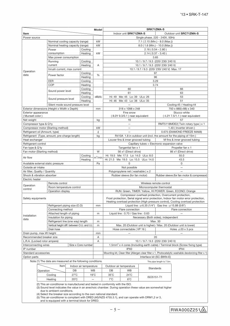
'13 • SRK-T-147
Model
Item
SRK71ZMA-S
Indoor unit SRK71ZMA-S Outdoor unit SRC71ZMA-S
Power source Single phase, 220 - 240V, 50Hz
Operation
data
Nominal cooling capacity (range) kW 7.1 ( 2.15 (Min.) - 8.0 (Max.))
Nominal heating capacity (range) kW 8.0 ( 1.6 (Min.) - 10.0 (Max.))
Power
consumption
Cooling
kW
2.16 ( 0.54 - 2.80 )
Heating 2.14 ( 0.37 - 3.40 )
Max power consumption 3.65
Running
current
Cooling
A
10.1 / 9.7 / 9.3 (220/ 230/ 240 V)
Heating 10.1 / 9.7 / 9.3 (220/ 230/ 240 V)
Inrush current, max current 10.1 / 9.7 / 9.3 (220/ 230/ 240 V) Max. 17
Power factorCooling
%97
Heating 96
EER Cooling 3.29
COP Heating 3.74
Sound power levelCooling
dB(A)
60 66
Heating 61 63
Sound pressure levelCooling Hi: 49 Me: 45 Lo: 39 ULo: 26 53
Heating Hi: 46 Me: 43 Lo: 38 ULo: 35 51
Silent mode sound pressure level — Cooling:45 / Heating:44
Exterior dimensions (Height x Width x Depth) mm 318 x 1098 x 248 750 x 880(+88) x 340
Exterior appearance( Munsell color )
Fine snow ( 8.0Y 9.3/0.1 ) near equivalent
Stucco white( 4.2Y 7.5/1.1 ) near equivalent
Net weight kg 16 57
Compressor type & Q'ty — RMT5118MDE2( Twin rotary type ) x 1
Compressor motor (Starting method) kW — 1.40 ( Inverter driven )
Refrigerant oil (Amount, type) — 0.675 (DIAMOND FREEZE MA68)
Refrigerant (Type, amount, pre-charge length) kg R410A 1.8 in outdoor unit (incl. the amount for the piping of 15m )
Heat exchanger Louver fins & inner grooved tubing M fins & inner grooved tubing
Refrigerant control Capillary tubes + Electronic expansion valve
Fan type & Q'ty Tangential fan x 1 Propeller fan x 1
Fan motor (Starting method) W 56 x1 (Direct drive) 86 x1 (Direct drive)
Air flow Cooling
m3/minHi: 19.5 Me: 17.5 Lo: 14.0 ULo: 8.0 55.0
Heating Hi: 21.5 Me: 19.5 Lo: 15.5 ULo: 14.0 43.5
Available external static pressure Pa 0 0
Outside air intake Not possible —
Air filter, Quality / Quantity Polypropylene net ( washable ) x 2 —
Shock & vibration absorber Rubber sleeve (for fan motor) Rubber sleeve (for fan motor & compressor)
Electric heater — —
Operation
control
Remote control Wireless remote control
Room temperature control Microcomputer thermostat
Operation display RUN: Green, TIMER: Yellow, HI POWER: Green, ECONO: Orange
Safety equipmentsCompressor overheat protection, Overcurrent protection,
Frost protection, Serial signal error protection, Indoor fan motor error protection,Heating overload protection (High pressure control), Cooling overload protection
Installation
data
Refrigerant piping size (O.D) mm Liquid line :φ6.35 (1/4") Gas line :φ15.88 (5/8")
Connecting method Flare connection Flare connection
Attached length of piping m Liquid line : 0.70 / Gas line : 0.63 —
Insulation for piping Necessary (Both sides), independent
Refrigerant line (one way) length m Max. 30
Vertical height diff. between O.U. and I.U. m Max. 20 (Outdoor unit is higher) / Max. 20 (Outdoor unit is lower)
Drain hose Hose connectable ( VP 16 ) Holes φ20 x 3 pcs
Drain pump, max lift height mm — —
Recommended breaker size A 20
L.R.A. (Locked rotor ampere) A 10.1 / 9.7 / 9.3 (220/ 230/ 240 V)
Interconnecting wires Size x Core number 1.5mm2 x 4 cores (Including earth cable) / Terminal block (Screw fixing type)
IP number IPX0 IPX4
Standard accessories Mounting kit, Clean filter (Allergen clear filter x 1, Photocatalytic washable deodorizing filter x 1)
Option parts Interface kit (SC-BIKN-E)
Note (1) The data are measured at the following conditions.
Item
Operation
Indoor air temperature Outdoor air temperatureStandards
DB WB DB WB
Cooling 27˚C 19˚C 35˚C 24˚CISO5151-T1
Heating 20˚C — 7˚C 6˚C
(2) This air-conditioner is manufactured and tested in conformity with the ISO.(3) Sound level indicates the value in an anechoic chamber. During operation these value are somewhat higher
due to ambient conditions.(4) Select the breaker size according to the own national standard.(5) This air-conditioner is compliant with DRED (AS/NZS 4755.3.1), and can operate with DRM1,2 or 3,
and is equipped with a terminal block for DRED.
The pipe length is 7.5m.
ARWA000Z251

- 6 -
'13 • SRK-T-147
Model
Item
SRK80ZMA-S
Indoor unit SRK80ZMA-S Outdoor unit SRC80ZMA-S
Power source Single phase, 220 - 240V, 50Hz
Operation
data
Nominal cooling capacity (range) kW 8.0 ( 2.15 (Min.) - 9.0 (Max.))
Nominal heating capacity (range) kW 9.0 ( 1.7 (Min.) - 10.5 (Max.))
Power
consumption
Cooling
kW
2.35 ( 0.54 - 3.00 )
Heating 2.57 ( 0.37 - 3.65 )
Max power consumption 3.65
Running
current
Cooling
A
11.0 / 10.5 / 10.1 (220/ 230/ 240 V)
Heating 12.0 / 11.5 / 11.0 (220/ 230/ 240 V)
Inrush current, max current 12.0 / 11.5 / 11.0 (220/ 230/ 240 V) Max. 17
Power factorCooling
%97
Heating 97
EER Cooling 3.40
COP Heating 3.50
Sound power levelCooling
dB(A)
65 69
Heating 63 70
Sound pressure levelCooling Hi: 51 Me: 47 Lo: 41 ULo: 26 56
Heating Hi: 48 Me: 45 Lo: 40 ULo: 37 57
Silent mode sound pressure level — Cooling:48 / Heating:50
Exterior dimensions (Height x Width x Depth) mm 318 x 1098 x 248 845 x 970x 370
Exterior appearance( Munsell color )
Fine snow ( 8.0Y 9.3/0.1 ) near equivalent
Stucco white( 4.2Y 7.5/1.1 ) near equivalent
Net weight kg 16 63
Compressor type & Q'ty — RMT5118MDE2( Twin rotary type ) x 1
Compressor motor (Starting method) kW — 1.40 ( Inverter driven )
Refrigerant oil (Amount, type) — 0.675 (DIAMOND FREEZE MA68)
Refrigerant (Type, amount, pre-charge length) kg R410A 2.2 in outdoor unit (incl. the amount for the piping of 15m )
Heat exchanger Louver fins & inner grooved tubing M fins & inner grooved tubing
Refrigerant control Capillary tubes + Electronic expansion valve
Fan type & Q'ty Tangential fan x 1 Propeller fan x 1
Fan motor (Starting method) W 56 x1 (Direct drive) 86 x1 (Direct drive)
Air flow Cooling
m3/minHi: 21.0 Me: 18.5 Lo: 15.0 ULo: 8.0 75.0
Heating Hi: 23.5 Me: 20.5 Lo: 17.0 ULo: 15.0 70.0
Available external static pressure Pa 0 0
Outside air intake Not possible —
Air filter, Quality / Quantity Polypropylene net ( washable ) x 2 —
Shock & vibration absorber Rubber sleeve (for fan motor) Rubber sleeve (for fan motor & compressor)
Electric heater — —
Operation
control
Remote control Wireless remote control
Room temperature control Microcomputer thermostat
Operation display RUN: Green, TIMER: Yellow, HI POWER: Green, ECONO: Orange
Safety equipmentsCompressor overheat protection, Overcurrent protection,
Frost protection, Serial signal error protection, Indoor fan motor error protection,Heating overload protection (High pressure control), Cooling overload protection
Installation
data
Refrigerant piping size (O.D) mm Liquid line :φ6.35 (1/4") Gas line :φ15.88 (5/8")
Connecting method Flare connection Flare connection
Attached length of piping m Liquid line : 0.70 / Gas line : 0.63 —
Insulation for piping Necessary (Both sides), independent
Refrigerant line (one way) length m Max. 30
Vertical height diff. between O.U. and I.U. m Max. 20 (Outdoor unit is higher) / Max. 20 (Outdoor unit is lower)
Drain hose Hose connectable ( VP 16 ) Holes φ20 x 3 pcs
Drain pump, max lift height mm — —
Recommended breaker size A 20
L.R.A. (Locked rotor ampere) A 12.0 / 11.5 / 11.0 (220/ 230/ 240 V)
Interconnecting wires Size x Core number 1.5mm2 x 4 cores (Including earth cable) / Terminal block (Screw fixing type)
IP number IPX0 IPX4
Standard accessories Mounting kit, Clean filter (Allergen clear filter x 1, Photocatalytic washable deodorizing filter x 1)
Option parts Interface kit (SC-BIKN-E)
Note (1) The data are measured at the following conditions.
Item
Operation
Indoor air temperature Outdoor air temperatureStandards
DB WB DB WB
Cooling 27˚C 19˚C 35˚C 24˚CISO5151-T1
Heating 20˚C — 7˚C 6˚C
(2) This air-conditioner is manufactured and tested in conformity with the ISO.(3) Sound level indicates the value in an anechoic chamber. During operation these value are somewhat
higher due to ambient conditions.(4) Select the breaker size according to the own national standard.(5) This air-conditioner iscompliant with DRED (AS/NZS 4755.3.1), and can operate with DRM1,2 or 3,
and is equipped with a terminal block for DRED.
The pipe length is 7.5m.
ARWA000Z251

- 7 -
'13 • SRK-T-147
Model
Item
SRK92ZMA-S
Indoor unit SRK92ZMA-S Outdoor unit SRC92ZMA-S
Power source Single phase, 220 - 240V, 50Hz
Operation
data
Nominal cooling capacity (range) kW 9.2 ( 2.4 (Min.) - 10.0 (Max.))
Nominal heating capacity (range) kW 10.0 ( 2.2 (Min.) - 11.2 (Max.))
Power
consumption
Cooling
kW
2.54 ( 0.47 - 3.07 )
Heating 2.84 ( 0.43 - 3.76 )
Max power consumption 3.80
Running
current
Cooling
A
11.9 / 11.4 / 10.9 (220/ 230/ 240 V)
Heating 13.3 / 12.7 / 12.2 (220/ 230/ 240 V)
Inrush current, max current 13.3 / 12.7 / 12.2 (220/ 230/ 240 V) Max. 17.5
Power factorCooling
%97
Heating 97
EER Cooling 3.62
COP Heating 3.52
Sound power levelCooling
dB(A)
65 67
Heating 64 67
Sound pressure levelCooling Hi: 51 Me: 47 Lo: 41 ULo: 26 56
Heating Hi: 49 Me: 46 Lo: 42 ULo: 38 54
Silent mode sound pressure level — Cooling:49 / Heating:50
Exterior dimensions (Height x Width x Depth) mm 318 x 1098 x 248 1300 x 970 x 370
Exterior appearance( Munsell color )
Fine snow ( 8.0Y 9.3/0.1 ) near equivalent
Stucco white( 4.2Y 7.5/1.1 ) near equivalent
Net weight kg 16 92
Compressor type & Q'ty — RMT5126MDE1( Twin rotary type ) x 1
Compressor motor (Starting method) kW — 4.0 ( Inverter driven )
Refrigerant oil (Amount, type) — 0.9 (DIAMOND FREEZE MA68)
Refrigerant (Type, amount, pre-charge length) kg R410A 3.15 in outdoor unit (incl. the amount for the piping of 15m )
Heat exchanger Louver fins & inner grooved tubing M fins & inner grooved tubing
Refrigerant control Capillary tubes + Electronic expansion valve
Fan type & Q'ty Tangential fan x 1 Propeller fan x 2
Fan motor (Starting method) W 56 x1 (Direct drive) 86 x2 (Direct drive)
Air flow Cooling
m3/minHi: 21.0 Me: 18.5 Lo: 15.0 ULo: 8.0 105.0
Heating Hi: 23.5 Me: 20.5 Lo: 17.0 ULo: 15.0 100.0
Available external static pressure Pa 0 0
Outside air intake Not possible —
Air filter, Quality / Quantity Polypropylene net ( washable ) x 2 —
Shock & vibration absorber Rubber sleeve (for fan motor) Rubber sleeve (for fan motor & compressor)
Electric heater — —
Operation
control
Remote control Wireless remote control
Room temperature control Microcomputer thermostat
Operation display RUN: Green, TIMER: Yellow, HI POWER: Green, ECONO: Orange
Safety equipmentsCompressor overheat protection, Overcurrent protection,
Frost protection, Serial signal error protection, Indoor fan motor error protection,Heating overload protection (High pressure control), Cooling overload protection
Installation
data
Refrigerant piping size (O.D) mm Liquid line :φ6.35 (1/4") Gas line :φ15.88 (5/8")
Connecting method Flare connection Flare connection
Attached length of piping m Liquid line : 0.70 / Gas line : 0.63 —
Insulation for piping Necessary (Both sides), independent
Refrigerant line (one way) length m Max. 30
Vertical height diff. between O.U. and I.U. m Max. 20 (Outdoor unit is higher) / Max. 20 (Outdoor unit is lower)
Drain hose Hose connectable ( VP 16 ) Holes φ20 x 3 pcs
Drain pump, max lift height mm — —
Recommended breaker size A 20
L.R.A. (Locked rotor ampere) A 13.7 / 12.7 / 12.2 (220/ 230/ 240 V)
Interconnecting wires Size x Core number 1.5mm2 x 4 cores (Including earth cable) / Terminal block (Screw fixing type)
IP number IPX0 IPX4
Standard accessories Mounting kit, Clean filter (Allergen clear filter x 1, Photocatalytic washable deodorizing filter x 1)
Option parts Interface kit (SC-BIKN-E)
Note (1) The data are measured at the following conditions.
item
Operation
Indoor air temperature Outdoor air temperatureStandards
DB WB DB WB
Cooling 27˚C 19˚C 35˚C 24˚CISO5151-T1
Heating 20˚C — 7˚C 6˚C
(2) This air-conditioner is manufactured and tested in conformity with the ISO.(3) Sound level indicates the value in an anechoic chamber. During operation these value are somewhat higher
due to ambient conditions.(4) Select the breaker size according to the own national standard.(5) This air-conditioner is compliant with DRED (AS/NZS 4755.3.1), and can operate with DRM1,2 or 3,
and is equipped with a terminal block for DRED.
The pipe length is 7.5m.
ARWA000Z251

- 8 -
'13 • SRK-T-147
2. EXTERIOR DIMENSIONS (1) Indoor units
Models SRK63ZMA-S, 71ZMA-S, 80ZMA-S, 92ZMA-S
RKW000Z403

- 9 -
'13 • SRK-T-147
(2) Outdoor units
Models SRC63ZMA-S, 71ZMA-S
RCR000Z008
- 10 -
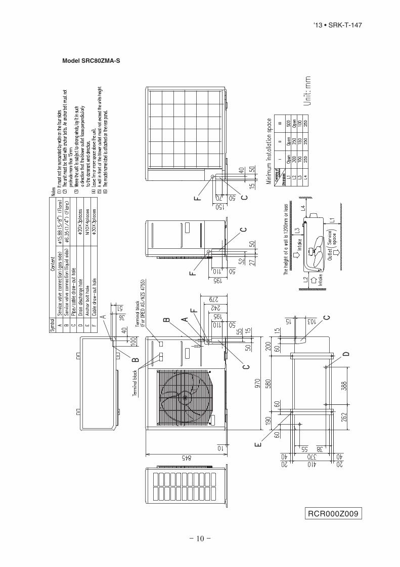
'13 • SRK-T-147
Model SRC80ZMA-S
RCR000Z009

- 11 -
'13 • SRK-T-147
Model SRC92ZMA-S
RCR000Z010
- 14 -
'13 • SRK-T-147
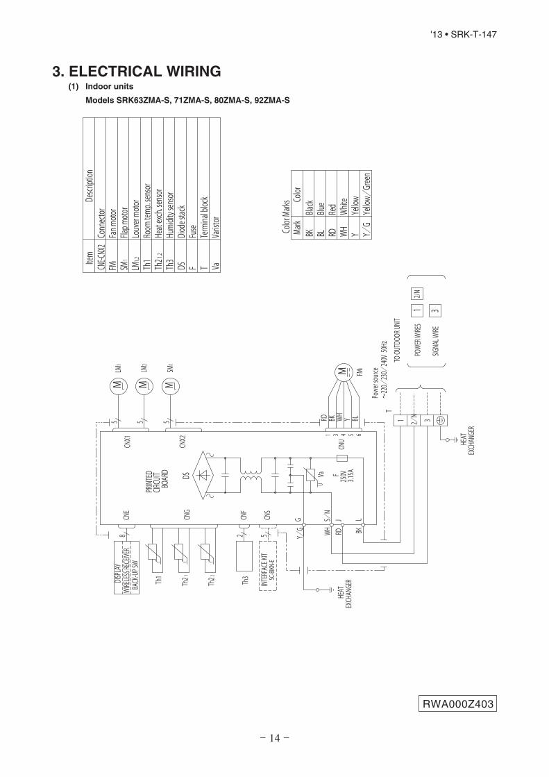
3. ELECTRICAL WIRING (1) Indoor units
Models SRK63ZMA-S, 71ZMA-S, 80ZMA-S, 92ZMA-S
RWA000Z403
250V
F
G
3.15A
S/N
Va
CNU
CNS
INTERFA
CE KIT
SC-BI
KN-E
CNG
CNE
DISPLA
YWI
RELESS RE
CEIVE
R
JCNF
U
MHE
AT
1 3 4 5 6
BACK
-UP S
W
52
EXCH
ANGE
RL
Th1
BOAR
DCIR
CUIT
ED
CNX2
CNX1
M M M
5 5 5
RDWHRD WHBK BLY
Y/G BK
Color
Mark
s
Blue
Black
BK
Red
BL RDWh
iteWH
Yellow/
Green
Y/G
Yellow
Y
Color
Mark
t
Th21
Th22 Th3
LM1
LM2
SM1
FMI
Heat
exch. se
nsor
Humi
dity s
ensor
Fan m
otor
Room
temp
. sensor
Flap m
otor
Th1
Th2
Th3
Diode
stack
DSFu
seF
Conn
ector
CNE-C
NX2
FMI
Term
inal bloc
kT
Louv
er mo
torLM
1,2
SM1
DS
1,2
Descr
iption
Item
Varistor
Va
t t
TO OUT
DOOR
UNIT
HEAT
EXCH
ANGE
R
1 2/N 3
POWE
R WIRE
S
SIGNA
L WIRE
12/N
3
Powe
r sou
rce~220/
230/
240V
50H
zT
8

- 15 -
'13 • SRK-T-147
RWC000Z262
(2) Outdoor units
Models SRC63ZMA-S, 71ZMA-S, 80ZMA-SPO
WER S
OURC
E
Color
RDMark
Oran
geOR
Yellow/
Green
Y/G
Black
BKBrow
nBR
Yellow
YEWhite
WH
Red
Mode
l
Power ca
ble, indo
or-outdo
or co
nnectin
g wire
s
MAX
runn
ing curre
ntPo
wer ca
ble siz
e(mm )2
(A)
MAX
pow
er ca
ble len
gth
(m)
indo
or-outdo
orwire size x nu
mbe
r Earth
wire
size
The specificatio
ns sh
own in th
e ab
ove table are for u
nits with
out h
eaters. For units with
heaters, refer
to th
e installation instructions or the
constru
ction instructions of the
indo
or unit.
Switchg
ear o
f Circuit b
reaker ca
pacity w
hich is ca
lculat
ed from
MAX
. over current sh
ould be chosen
along
the regu
lations in each coun
try.
The cable specificatio
ns are ba
sed on
the assumption that a metal or plas
tic co
nduit is u
sed with
no
more than
three cables co
ntain
ed in a cond
uit a
nd a volta
ge drop is 2%
. For an
installation fallin
gou
tside of th
ese cond
ition
s, please fo
llow th
e internal cabling regu
lations. A
dapt it to
the regu
lation
in effe
ct in each coun
try.
Descrip
tion
Item
63
172.5
301.5
mm x 4
1.571
Conn
ector
CN20
S
Electr
ic expa
nsion
valve(
coil)
EEV
Fan m
otor
FMo
Reactor
RTerm
inal block
TB1,2
,3
Compressor m
otor
CM
Solen
oid va
lve fo
r 4 way va
lve20
S
Heat ex
chan
ger sen
sor(ou
tdoo
r unit)
TH1
Outdoo
r air t
emp.s
ensor
TH2
TH3
Discha
rge p
ipe t
emp.s
ensor
312
[
]TO
INDO
OR UNIT
POWER W
IRES
SIGNA
L WIRE
N
80
2
~22
0-240
V 50H
z
CNTH
CNEEV
CNFA
N
M
T2
T1
S(BK
)
(WH)
(RD
)
V WU
PWB AS
SY (MAIN)
M
++
R
TRAN
SISTO
RPO
WER
CIRC
UIT
SWITC
HING
250V 3.15A
F1
250V
20A
F2
F3 25
0V 1A
WVUP N
CNTH
CNEEV
CNFA
N
t゜
+AC
TIVE
FILTER
UNIT
250V
20A
F8
R
(OR)
(YE)
S-2
(BK
)
(WH)
(WH)
(BK
)
PWB AS
SY (SU
B)
S-1
CNSU
BCN
MAIN
S R R
(BK
)
(WH)
G1(Y/
G)
(BR
)
ININ OUT
S R OO
NL250V
20A
FUSE
21 N 3(Y/
G)
(Y/
G)
CN20S
C-2
(RD
)
20S
TB1
TB2
TERM
INAL
BLOC
K
22
2
TH1
TH2
TH3
EEV
FMo
BLOC
K
TERM
INAL
(WH)
t゜
t゜
POWER
(Y/
G)G3
D1 D3D2 C
TB3
BLOC
KTERM
INAL
4
(YE)
(RD
)(BL)
(BK
)
(Y/
G)
250V 10A
F10
4
(WH)
(BK
)
PWB AS
SY(DR
ED)
CNPO
WER
CNDR
ED
CNDR
M
(RD
)
(BK
)
CNDR
M
MS
CM3~
(mm )2

- 16 -
'13 • SRK-T-147
Model SRC92ZMA-S
POWE
R SOU
RCE
Color
RDMark
Oran
geOR
Yellow/
Green
Y/G
Black
BKBrow
nBR
Yellow
YEWhite
WH
Red
Mode
l
Power ca
ble, indo
or-outdo
or co
nnectin
g wire
s
MAX
runn
ing curre
ntPo
wer ca
ble siz
e(mm )2
(A)
MAX
pow
er ca
ble len
gth
(m)
Indo
or-outdo
orwire size x nu
mbe
r Earth
wire
size
The specificatio
ns sh
own in th
e ab
ove table are for u
nits with
out h
eaters. For units with
heaters, refer
to th
e installation instructions or the
constru
ction instructions of the
indo
or unit.
Switchg
ear o
f Circuit b
reaker ca
pacity w
hich is ca
lculat
ed from
MAX
. over current sh
ould be chosen
along
the regu
lations in each coun
try.
The cable specificatio
ns are ba
sed on
the assumption that a metal or plas
tic co
nduit is u
sed with
no
more than
three cables co
ntain
ed in a cond
uit a
nd a volta
ge drop is 2%
. For an
installation fallin
gou
tside of th
ese cond
ition
s, please fo
llow th
e internal cabling regu
lations. A
dapt it to
the regu
lation
in effe
ct in each coun
try.
Descrip
tion
Item
17.5
2.530
1.5mm x 4
1.592
Conn
ector
CN20
S
Electr
ic expa
nsion
valve(
coil)
EEV
Fan m
otor 1
FMo1
Reactor
RTerm
inal block
TB1,2
,3
Compressor m
otor
CM
Solen
oid va
lve fo
r 4 way va
lve20
S
Heat ex
chan
ger sen
sor(ou
tdoo
r unit)
TH2
Outdoo
r air t
emp.s
ensor
TH3
TH4
Discha
rge p
ipe t
emp.s
ensor
312
[
]TO
INDO
OR UNIT
POWER W
IRES
SIGNA
L WIRE
N
2
~22
0-240
V 50H
z
CNTH
CNEEV
CNFA
N1,2
Fan m
otor 2
FMo2
(mm )2
TH4
TH3
TH2
M
T2
T1
S
(BK
)
(WH)
(RD
)
PWB AS
SY (MAIN)
MS
R
EEV
CM
CNTH
CNEEV
3~
R(OR
)(YE)
S-2
(BK
)
(WH)
(WH)
PWB AS
SY (SU
B)
S-1
CNSU
BCN
MAIN
S R (BK
)
(WH)
(Y/
G)
(BK
)
ININ
S R
00
NL
250V
20A
FUSE
21 N 3
(Y/
G)
(Y/
G)
TB1
TB2
BLOC
K
20S
CN20S
(BK)(WH)
4
V WU
++
TRAN
SISTO
RPO
WER
CIRC
UIT
POWER
250V
3.15A
F1
250V
20A
F2
F3 25
0V 3.15A
WVUP N
+AC
TIVE
FILTER
UNIT
250V
20A
F8
SWITC
HING
(RD
)C-2
CNFA
N
5
C-1
4CN
FAN0
2 2
F2
F1
CNFA
N1CN
FAN2
250V 1A
250V 1A
5
FMo2
FMo1
(RD
)
5
G1
55
2CN
20V
CN20V
CNA
MM
G3(Y/
G)
C
PWB AS
SY(DR
ED)
CNPO
WER
CNDR
ED
CNDR
M
TB3
(YE)
(RD
)(BL)
(BK
)
(WH)
(BK
)
4
CNDR
M
D1 D2 D3
(Y/
G)
t゜
t゜
t゜
22
2
TERM
INAL
BLOC
KTERM
INAL
BLOC
KTERM
INAL
Blue
BL
RWC000Z264

- 42 -
'13 • SRK-T-147
○
○ ○ ○ ○ ○ ○ ○ ○ ○ ○ ○ ○ ○
R410A
RE
FR
IGE
RA
NT
US
ED
WA
LL
TY
PE
AIR
CO
ND
ITIO
NE
R
INS
TA
LLA
TIO
NM
AN
UA
LFO
RIN
DO
OR
UN
IT
RK
W012A
411
○○ ○
○ ○
○○ ○
○
○ ○
WA
RN
ING
•In
sta
lla
tio
nm
ust
be
ca
rrie
do
ut
by
the
qu
alifi
ed
insta
lle
r.
Ifyo
uin
sta
llth
esys
tem
by
yours
elf,
itm
ay
cause
serio
us
tro
ub
lesuch
as
wate
rle
aks,
ele
ctr
icshocks,
fire
and
pers
onali
nju
ry,
as
are
sult
ofa
sys
tem
malfu
nctio
n.
Do
not
carr
yo
ut
the
insta
llation
and
main
tenance
wo
rkexcep
t
the
by
qualif
ied
insta
ller.
•In
sta
llth
esyste
min
full
ac
co
rda
nc
ew
ith
the
insta
lla
tio
nm
an
ua
l.
Inco
rrect
insta
llatio
nm
ay
cause
burs
ts,
pers
onali
nju
ry,
wate
rle
aks,
ele
ctr
ic
sho
cks
and
fire.
•B
esu
reto
use
on
lyfo
rh
ou
se
ho
lda
nd
resid
en
ce
.
Ifth
isap
plia
nce
isin
sta
lled
inin
ferio
renvi
ronm
ent
such
as
machin
esho
p
and
etc
.,it
can
cause
malfu
nction.
•U
se
the
ori
gin
ala
cc
esso
rie
sa
nd
the
sp
ec
ifie
dc
om
po
ne
nts
for
insta
lla
tio
n.
Ifp
art
so
ther
than
tho
se
pre
scrib
ed
by
us
are
used
,It
may
cause
wate
r
leaks,
ele
ctr
icsho
cks,
fire
and
pers
onali
nju
ry.
•In
sta
llth
eu
nit
ina
loc
ati
on
wit
hg
oo
dsu
pp
ort
.
Unsuitab
lein
sta
llatio
nlo
cations
can
cause
the
unit
tofa
lland
cause
mate
riald
am
ag
eand
pers
onali
nju
ry.
•V
en
tila
teth
ew
ork
ing
are
aw
ell
inth
ee
ve
nt
of
refr
ige
ran
tle
ak
ag
e
du
rin
gin
sta
lla
tio
n.
Ifth
ere
frig
era
nt
com
es
into
co
nta
ct
with
naked
flam
es,
po
iso
no
us
gas
is
pro
duced
.
•W
he
nin
sta
llin
gin
sm
all
roo
ms,
tak
ep
reve
nti
on
me
asu
res
no
tto
exc
ee
dth
ed
en
sit
ylim
ito
fre
frig
era
nt
inth
ee
ve
nt
of
lea
ka
ge
,
refe
rre
db
yth
efo
rmu
la(a
cc
ord
an
ce
wit
hIS
O5
149
).
Ifth
ed
ensity
ofre
frig
era
nt
exceed
sth
elim
it,
ple
ase
co
nsult
the
deale
rand
insta
llth
eve
ntila
tion
sys
tem
,oth
erw
ise
lack
ofoxyg
en
can
occur,
whic
h
can
cause
serio
us
accid
ent.
•A
fte
rc
om
ple
ted
insta
lla
tio
n,c
he
ck
tha
tn
ore
frig
era
nt
lea
ks
fro
m
the
syste
m.
Ifre
frig
era
nt
leaks
into
the
roo
mand
co
mes
into
co
nta
ct
with
an
ove
nor
oth
er
hot
surf
ace,
po
iso
no
us
gas
isp
rod
uced
.
•U
se
the
pre
sc
rib
ed
pip
es,
fla
ren
uts
an
dto
ols
for
R4
10
A.
Usin
gexis
ting
part
s(fo
rR
22
or
R4
07C
)can
cause
the
unit
failu
reand
serio
us
accid
ents
due
tob
urs
tofth
ere
frig
era
nt
circuit.
•T
igh
ten
the
fla
ren
ut
by
torq
ue
wre
nc
hw
ith
sp
ec
ifie
dm
eth
od
.
Ifth
efla
renut
were
tig
hte
ned
with
excess
torq
ue,th
ism
ay
cause
burs
tand
refr
igera
nt
leakag
eafter
alo
ng
perio
d.
•T
he
ele
ctr
ica
lin
sta
lla
tio
nm
ust
be
ca
rrie
do
ut
by
the
qu
alifi
ed
ele
ctr
icia
nin
ac
co
rda
nc
ew
ith
“th
en
orm
for
ele
ctr
ica
lw
ork
”a
nd
“na
tio
na
lw
irin
gre
gu
lati
on
”,a
nd
the
syste
mm
ust
be
co
nn
ec
ted
to
the
de
dic
ate
dc
irc
uit
.
Po
wer
sup
ply
with
insuffic
ient
cap
acity
and
incorr
ect
functio
nd
one
by
imp
rop
er
work
can
cause
ele
ctr
icshocks
and
fire.
•B
esu
reto
sh
ut
off
the
po
we
rb
efo
resta
rtin
ge
lec
tric
alw
ork
.
Failu
reto
shut
off
the
po
wer
can
cause
ele
ctr
icshocks,
unit
failu
reo
r
inco
rrect
functio
no
feq
uip
ment.
•B
esu
reto
use
the
ca
ble
sc
on
form
ed
tosa
fety
sta
nd
ard
an
dc
ab
le
am
pa
cit
yfo
rp
ow
er
dis
trib
uti
on
wo
rk.
Unco
nfo
rmab
lecab
les
can
cause
ele
ctr
icle
ak,
ano
malo
us
heat
pro
ductio
n
or
fire.
•T
his
ap
plia
nc
em
ust
be
co
nn
ec
ted
tom
ain
po
we
rsu
pp
lyb
ym
ea
ns
of
ac
irc
uit
bre
ak
er
or
sw
itc
h(f
use
:20
A)
wit
ha
co
nta
ct
se
pa
rati
on
of
at
lea
st
3m
m.
•W
he
np
lug
gin
gth
isa
pp
lia
nc
e,a
plu
gc
on
form
ing
toth
en
orm
IEC
60
88
4-1
mu
st
be
use
d.
•U
se
the
pre
sc
rib
ed
ca
ble
sfo
re
lec
tric
alc
on
ne
cti
on
,ti
gh
ten
the
ca
ble
sse
cu
rely
inte
rmin
alb
loc
ka
nd
relie
ve
the
ca
ble
sc
orr
ec
tly
to
pre
ve
nt
ove
rlo
ad
ing
the
term
ina
lb
loc
ks.
Lo
ose
co
nnections
or
cab
lem
ounting
scan
cause
ano
malo
us
heat
pro
ductio
no
rfir
e.
•A
rra
ng
eth
ew
irin
gin
the
co
ntr
olb
ox
so
tha
tit
ca
nn
ot
be
pu
sh
ed
up
furt
he
rin
toth
eb
ox.
Insta
llth
ese
rvic
ep
an
elc
orr
ec
tly.
Incorr
ect
insta
llatio
nm
ay
result
ino
verh
eating
and
fire.
•B
esu
reto
sw
itc
ho
ffth
ep
ow
er
su
pp
lyin
the
eve
nt
of
insta
lla
tio
n,
insp
ec
tio
no
rse
rvic
ing
.
Ifth
ep
ow
er
sup
ply
isno
tshut
off,
there
isa
risk
ofele
ctr
icsho
cks,
unit
failu
reor
pers
onali
nju
ryd
ue
toth
eunexp
ecte
dsta
rto
ffa
n.
•B
esu
reto
we
ar
pro
tec
tive
go
gg
les
an
dg
love
sw
hile
at
wo
rk.
•E
art
hle
ak
ag
eb
rea
ke
rm
ust
be
insta
lle
d.
Ifth
eeart
hle
akag
eb
reaker
isno
tin
sta
lled
,it
can
cause
ele
ctr
icshocks.
CA
UT
ION
•U
se
the
cir
cu
itb
rea
ke
ro
fc
orr
ec
tc
ap
ac
ity.C
irc
uit
bre
ak
er
sh
ou
ld
be
the
on
eth
at
dis
co
nn
ec
ta
llp
ole
su
nd
er
ove
rc
urr
en
t.
Usin
gth
ein
corr
ect
one
could
cause
the
sys
tem
failu
reand
fire.
•In
sta
llis
ola
tor
or
dis
co
nn
ec
tsw
itc
ho
nth
ep
ow
er
su
pp
lyw
irin
gin
ac
co
rda
nc
ew
ith
the
loc
alc
od
es
an
dre
gu
lati
on
s.
The
iso
lato
rsho
uld
be
locked
inO
FF
sta
tein
acco
rdance
with
EN
60
20
4-1
.
•B
esu
reto
insta
llin
do
or
un
itp
rop
erl
ya
cc
ord
ing
toth
ein
sta
lla
tio
n
ma
nu
alin
ord
er
toru
no
ffth
ed
rain
ag
esm
oo
thly
.
Imp
rop
er
insta
llatio
no
fin
do
or
unit
can
cause
dro
pp
ing
wate
rin
toth
ero
om
and
dam
ag
ing
pers
onalp
rop
ert
y.
•In
sta
llth
ed
rain
ag
ep
ipe
toru
no
ffd
rain
ag
ese
cu
rely
ac
co
rdin
gto
the
insta
lla
tio
nm
an
ua
l.
Incorr
ect
insta
llation
ofth
ed
rain
ag
ep
ipe
can
cause
dro
pp
ing
wate
rin
toth
e
room
and
dam
ag
ing
pers
onalp
rop
ert
y.
•B
esu
reto
insta
llth
ed
rain
ag
ep
ipe
wit
hd
esc
en
din
gslo
pe
of
1/1
00
or
mo
re,
an
dn
ot
tom
ak
etr
ap
sa
nd
air
-ble
ed
ing
s.
Check
ifth
ed
rain
ag
eru
ns
off
secure
lyd
uring
co
mm
issio
nin
gand
ensure
the
sp
ace
for
insp
ectio
nand
main
tenance.
•S
ec
ure
asp
ac
efo
rin
sta
lla
tio
n,
insp
ec
tio
na
nd
ma
inte
na
nc
e
sp
ec
ifie
din
the
ma
nu
al.
Insuffic
ient
sp
ace
can
result
inaccid
ent
such
as
pers
onali
nju
ryd
ue
to
falling
fro
mth
ein
sta
llatio
np
lace.
•F
or
insta
lla
tio
nw
ork
,b
ec
are
fuln
ot
tog
et
inju
red
wit
hth
eh
ea
t
exc
ha
ng
er,
pip
ing
fla
rep
ort
ion
or
sc
rew
se
tc.
•B
esu
reto
insu
late
the
refr
ige
ran
tp
ipe
sso
as
no
tto
co
nd
en
se
the
am
bie
nt
air
mo
istu
reo
nth
em
.
Insuffic
ient
insula
tio
ncan
cause
co
nd
ensation,
whic
hcan
lead
tom
ois
ture
dam
ag
eo
nth
eceiling
,flo
or,
furn
iture
and
any
oth
er
valu
ab
les.
•W
he
np
erf
orm
the
air
co
nd
itio
ne
ro
pe
rati
on
(co
olin
go
rd
ryin
go
pe
ra-
tio
n)in
wh
ich
ve
nti
lato
ris
insta
lle
din
the
roo
m.In
this
ca
se
,u
sin
gth
e
air
co
nd
itio
ne
rin
pa
ralle
lw
ith
the
ve
nti
lato
r,th
ere
isth
ep
ossib
ilit
y
tha
td
rain
wa
ter
ma
yb
ac
kfl
ow
ina
cc
ord
an
ce
wit
hth
ero
om
lap
se
into
the
ne
ga
tive
pre
ssu
resta
tus.T
he
refo
re,se
tu
pth
eo
pe
nin
gp
ort
su
ch
as
inc
orp
ora
teth
ea
irin
toth
ero
om
tha
tm
ay
ap
pro
pri
ate
tove
nti
la-
tio
n(F
or
exa
mp
le;O
pe
nth
ed
oo
ra
litt
le).
Ina
dd
itio
n,ju
st
as
ab
ove
,so
se
tu
pth
eo
pe
nin
gp
ort
ifth
ero
om
lap
se
into
ne
ga
tive
pre
ssu
resta
tus
du
eto
reg
iste
ro
fth
ew
ind
for
the
hig
hri
se
ap
art
me
nt
etc
.
•B
esu
reto
pe
rfo
rma
irti
gh
tne
ss
test
by
pre
ssu
rizin
gw
ith
nit
rog
en
ga
sa
fte
rc
om
ple
ted
refr
ige
ran
tp
ipin
gw
ork
.
Ifth
ed
ensity
ofre
frig
era
nt
exceed
sth
elim
itin
the
eve
nt
ofre
frig
era
nt
leakag
ein
the
sm
all
roo
m,la
ck
ofo
xyg
en
can
occur,
whic
hcan
cause
serio
us
accid
ents
.
•D
on
ot
insta
llth
eu
nit
inth
elo
ca
tio
ns
liste
db
elo
w.
•Lo
catio
ns
where
carb
on
fiber,
meta
lpow
der
or
any
po
wd
er
isflo
ating
.
•Lo
catio
ns
where
any
sub
sta
nces
that
can
affect
the
unit
such
as
sulp
hid
e
gas,
chlo
rid
eg
as,
acid
and
alk
alin
ecan
occur.
•Vehic
les
and
ship
s.
•Lo
catio
ns
where
co
sm
etic
or
sp
ecia
lsp
rays
are
often
used
.
•Lo
catio
ns
with
direct
exp
osure
ofo
ilm
ist
and
ste
am
such
as
kitchen
and
machin
ep
lant.
•Lo
catio
ns
where
any
machin
es
whic
hg
enera
tehig
hfr
eq
uency
harm
onic
s
are
used
.
•Lo
catio
ns
with
salty
atm
osp
here
ssuch
as
co
astlin
es.
•Lo
catio
ns
with
heavy
sno
w(If
insta
lled
,b
esure
top
rovi
de
base
flam
eand
sno
whoo
dm
entio
ned
inth
em
anual).
•Lo
catio
ns
where
the
unit
isexp
osed
tochim
ney
sm
oke.
•Lo
catio
ns
at
hig
haltitud
e(m
ore
than
10
00
mhig
h).
•Lo
catio
ns
with
am
mo
nic
atm
osp
here
s.
•Lo
catio
ns
where
heat
rad
iatio
nfro
mo
ther
heat
so
urc
ecan
affect
the
unit.
•Lo
catio
ns
witho
ut
go
od
air
circula
tion.
•Locatio
ns
with
any
obst
acle
sw
hic
hcan
pre
ventin
letand
outle
tair
ofth
eunit.
•Lo
catio
ns
where
short
circuit
ofair
can
occur
(incase
ofm
ultip
leunits
insta
llatio
n).
•Lo
catio
ns
where
str
ong
air
blo
ws
ag
ain
st
the
air
outlet
ofoutd
oo
runit.
•Lo
catio
ns
where
so
meth
ing
locate
dab
ove
the
unit
could
fall.
Itcan
cause
rem
ark
ab
led
ecre
ase
inp
erf
orm
ance,co
rro
sio
nand
dam
ag
e
ofco
mp
onents
,m
alfu
nctio
nand
fire.
•D
on
ot
insta
llth
ein
do
or
un
itin
the
loc
ati
on
sliste
db
elo
w(B
esu
re
toin
sta
llth
ein
do
or
un
ita
cc
ord
ing
toth
ein
sta
lla
tio
nm
an
ua
lfo
r
ea
ch
mo
de
lb
ec
au
se
ea
ch
ind
oo
ru
nit
ha
se
ac
hlim
ita
tio
n).
•Lo
catio
ns
with
any
ob
sta
cle
sw
hic
hcan
pre
vent
inle
tand
outlet
air
ofth
e
unit.
•Lo
catio
ns
where
vib
ratio
ncan
be
am
plif
ied
due
toin
suffic
ient
str
eng
tho
f
str
uctu
re.
•Lo
catio
ns
where
the
infr
are
dre
ceiv
er
isexp
osed
toth
ed
irect
sunlig
ht
or
the
str
ong
light
beam
(incase
ofth
ein
frare
dsp
ecifi
catio
nunit).
•Lo
catio
ns
where
an
eq
uip
ment
affecte
db
yhig
hharm
onic
sis
pla
ced
(TV
set
or
rad
iore
ceiv
er
isp
laced
within
1m
).
•Lo
catio
ns
where
dra
inage
canno
tru
no
ffsafe
ly.
Itcan
affect
perf
orm
ance
or
functio
nand
etc
.
•D
on
ot
insta
llth
eu
nit
ne
ar
the
loc
ati
on
wh
ere
lea
ka
ge
of
co
mb
usti
ble
ga
se
sc
an
oc
cu
r.
Ifle
aked
gases
accum
ula
tearo
und
the
unit,
itcan
cause
fire.
•D
on
ot
insta
llth
eu
nit
wh
ere
co
rro
siv
eg
as
(su
ch
as
su
lfu
rou
sa
cid
ga
se
tc.)
or
co
mb
usti
ble
ga
s(s
uc
ha
sth
inn
er
an
dp
etr
ole
um
ga
se
s)
ca
na
cc
um
ula
teo
rc
olle
ct,
or
wh
ere
vo
lati
lec
om
bu
sti
ble
su
bsta
nc
es
are
ha
nd
led
.
Co
rro
siv
eg
as
can
cause
co
rro
sio
nofheat
exchang
er,
bre
akage
ofp
lastic
part
sand
etc
.A
nd
co
mb
ustib
legas
can
cause
fire.
•D
on
ot
use
the
ind
oo
ru
nit
at
the
pla
ce
wh
ere
wa
ter
sp
lash
es
ma
y
oc
cu
rsu
ch
as
inla
un
dri
es.
Sin
ce
the
ind
oor
unit
isnot
wate
rpro
of,
itcan
cause
ele
ctr
icshocks
and
fire.
•D
on
ot
insta
lln
or
use
the
syste
mc
lose
toth
ee
qu
ipm
en
tth
at
ge
ne
rate
se
lec
tro
ma
gn
eti
cfi
eld
so
rh
igh
fre
qu
en
cy
ha
rmo
nic
s.
Eq
uip
ment
such
as
inve
rters
,sta
nd
by
genera
tors
,m
ed
icalh
igh
freq
uency
eq
uip
ments
and
tele
co
mm
unic
atio
neq
uip
ments
can
affect
the
sys
tem
,and
cause
malfu
nctio
ns
and
bre
akd
ow
ns.
The
sys
tem
can
als
oaffect
med
ical
eq
uip
ment
and
tele
co
mm
unic
ation
eq
uip
ment,
and
ob
str
uct
its
functio
no
r
cause
jam
min
g.
•D
on
ot
pla
ce
an
yva
ria
ble
sw
hic
hw
illb
ed
am
ag
ed
by
ge
ttin
gw
et
un
de
rth
ein
do
or
un
it.
When
the
rela
tive
hum
idity
ishig
her
than
80
%o
rd
rain
age
pip
eis
clo
gg
ed
,
co
nd
ensation
or
dra
inag
ew
ate
rcan
dro
pand
itcan
cause
the
dam
ag
eo
f
valu
ab
les.
•D
on
ot
insta
llth
ere
mo
tec
on
tro
la
tth
ed
ire
ct
su
nlig
ht.
Itcan
cause
malfu
nctio
nor
defo
rmatio
no
fth
ere
mo
teco
ntr
ol.
•D
on
ot
use
the
un
itfo
rsp
ec
ialp
urp
ose
ssu
ch
as
sto
rin
gfo
od
s,
co
olin
gp
rec
isio
nin
str
um
en
tsa
nd
pre
se
rva
tio
no
fa
nim
als
,p
lan
tso
r
art
.
Itcan
cause
the
dam
age
ofth
eitem
s.
•D
on
ot
use
an
ym
ate
ria
lso
the
rth
an
afu
se
wit
hth
ec
orr
ec
tra
tin
gin
the
loc
ati
on
wh
ere
fuse
sa
reto
be
use
d.
Co
nnecting
the
circuit
with
co
pp
er
wire
or
oth
er
meta
lthre
ad
can
cause
unit
failu
reand
fire.
•D
on
ot
tou
ch
an
yb
utt
on
sw
ith
we
th
an
ds.
Itcan
cause
ele
ctr
icsho
cks.
•D
on
ot
tou
ch
an
yre
frig
era
nt
pip
es
wit
hyo
ur
ha
nd
sw
he
nth
e
syste
mis
ino
pe
rati
on
.
During
op
era
tio
nth
ere
frig
era
nt
pip
es
beco
me
extr
em
ely
ho
to
rextr
em
ely
co
ldd
ep
end
ing
the
op
era
ting
cond
itio
n,
and
itcan
cause
burn
inju
ryor
fro
st
inju
ry.
•C
arr
yo
ut
the
ele
ctr
ica
lw
ork
for
gro
un
dle
ad
wit
hc
are
.
Do
no
tconnect
the
gro
und
lead
toth
eg
as
line,w
ate
rlin
e,lig
htn
ing
co
nd
ucto
ror
tele
pho
ne
line’s
gro
und
lead
.In
co
rrect
gro
und
ing
can
cause
unit
faults
such
as
ele
ctr
icsho
cks
due
tosho
rt-c
ircuitin
g.
•D
on
ot
pu
tth
ed
rain
ag
ep
ipe
dir
ec
tly
into
dra
ina
ge
ch
an
ne
lsw
he
re
po
iso
no
us
ga
se
ssu
ch
as
su
lph
ide
ga
sc
an
oc
cu
r.
Po
iso
no
us
gases
will
flow
into
the
room
thro
ugh
dra
inag
ep
ipe
and
serio
usly
affect
the
user’s
health
and
safe
ty.
This
can
als
ocause
the
co
rro
sio
no
fth
ein
do
or
unit
and
are
sultant
unit
failu
reor
refr
igera
nt
leak.
•E
nsu
reth
at
no
air
en
ters
inth
ere
frig
era
nt
cir
cu
itw
he
nth
eu
nit
is
insta
lle
da
nd
rem
ove
d.
Ifair
ente
rsin
the
refr
igera
nt
circuit,
the
pre
ssure
inth
ere
frig
era
nt
circuit
becom
es
too
hig
h,
whic
hcan
cause
burs
tand
pers
onali
nju
ry.
•D
on
ot
pro
ce
ssin
g,
sp
lic
eth
ep
ow
er
co
rd,
or
sh
are
aso
ck
et
wit
h
oth
er
po
we
rp
lug
s.
This
may
cause
fire
or
ele
ctr
icsho
ck
due
tod
efe
cting
co
nta
ct,
defe
cting
insula
tio
nand
ove
r-curr
ent
etc
.
•D
on
ot
bu
nd
lin
g,
win
din
go
rp
roc
essin
gfo
rth
ep
ow
er
co
rd.
Or,
do
no
td
efo
rmin
gth
ep
ow
er
plu
gd
ue
totr
ea
dit
.
This
may
cause
fire
or
heating
.
•D
on
ot
ve
nt
R4
10
Ain
toth
ea
tmo
sp
he
re:R
41
0A
isa
flu
ori
na
ted
gre
en
ho
use
ga
s,
co
ve
red
by
the
Kyo
toP
roto
co
lw
ith
Gro
va
l
Wa
rmin
gP
ote
nti
al(G
WP
)=19
75
.
•D
on
ot
run
the
un
itw
ith
rem
ove
dp
an
els
or
pro
tec
tio
ns.
Touchin
gro
tating
eq
uip
ments
,ho
tsurf
aces
or
hig
hvo
ltag
ep
art
scan
cause
pers
onali
nju
ryd
ue
toentr
ap
ment,
burn
or
ele
ctr
icsho
cks.
•D
on
ot
pe
rfo
rma
ny
ch
an
ge
of
pro
tec
tive
de
vic
eit
se
lfo
rit
sse
tup
co
nd
itio
n.
The
forc
ed
op
era
tio
nb
ysho
rt-c
ircuitin
gp
rote
ctive
devi
ce
ofp
ressure
sw
itch
and
tem
pera
ture
co
ntr
olle
ro
rth
euse
ofno
nsp
ecifi
ed
co
mp
onent
can
cause
fire
or
burs
t.
WA
RN
ING
SA
FE
TY
PR
EC
AU
TIO
NS
•R
ead
the
“SA
FE
TY
PR
EC
AU
TIO
NS
”care
fully
first
ofall
and
str
ictly
follo
wit
during
the
insta
llatio
nw
ork
ino
rder
top
rote
ct
yours
elf.
•T
he
pre
cautionary
item
sm
entio
ned
belo
ware
dis
ting
uis
hed
into
two
leve
ls,
and
.
:W
rong
insta
llatio
nw
ould
cause
serious
co
nseq
uences
such
as
inju
ries
or
death
.
:W
rong
insta
llatio
nm
ight
cause
serious
co
nseq
uences
dep
end
ing
on
circum
sta
nces.
Bo
thm
entio
ns
the
imp
ort
ant
item
sto
pro
tect
your
health
and
safe
tyso
str
ictly
follo
wth
em
by
any
means.
•B
esure
toconfir
mno
anom
aly
on
the
eq
uip
ment
by
com
mis
sio
nin
gafter
com
-
ple
ted
insta
llatio
nand
exp
lain
the
op
era
ting
meth
od
sas
well
as
the
main
tenance
meth
od
softh
iseq
uip
ment
toth
euser
accord
ing
toth
eow
ner’s
manual.
•K
eep
the
insta
llatio
nm
anualt
og
eth
er
with
ow
ner’s
manuala
ta
pla
ce
where
any
user
can
read
at
any
tim
e.
More
ove
rif
necessary
,ask
tohand
them
toa
new
user.
•Fo
rin
sta
lling
qualif
ied
pers
onnel,
take
pre
cautions
inre
sp
ect
toth
em
selv
es
by
usin
gsuitab
lep
rote
ctive
clo
thin
g,
gro
ves,
etc
.,and
then
perf
orm
the
insta
llatio
nw
ork
s.
•P
lease
pay
att
ention
no
tto
fall
do
wn
the
too
ls,
etc
.w
hen
insta
lling
the
unit
at
the
hig
hp
ositio
n.
•If
unusualn
ois
ecan
be
heard
during
op
era
tio
n,
co
nsult
the
deale
r.
•T
he
meanin
gs
of“M
ark
s”
used
here
are
show
nas
follo
ws:
Neve
rd
oit
und
er
any
circum
sta
nces.
Alw
ays
do
itacco
rdin
gto
the
instr
uction.
CA
UT
ION
WA
RN
ING
CA
UT
ION
WA
RN
ING
•T
his
insta
lla
tio
nm
an
ua
lillu
str
ate
sth
em
eth
od
of
insta
llin
ga
nin
do
or
un
it.
•F
or
ele
ctr
ica
lw
irin
gw
ork
,p
lea
se
se
ein
str
uc
tio
ns
se
to
ut
on
the
ba
ck
sid
e.
•F
or
ou
tdo
or
un
itin
sta
lla
tio
na
nd
refr
ige
ran
tp
ipin
g,
ple
ase
refe
rto
pa
ge
35.
•A
wir
ed
rem
ote
co
ntr
olu
nit
issu
pp
lie
dse
pa
rate
lya
sa
no
pti
on
alp
art
.
•W
he
nin
sta
llth
eu
nit
,b
esu
reto
ch
ec
kw
he
the
rth
ese
lec
tio
no
f
insta
lla
tio
np
lac
e,
po
we
rsu
pp
lysp
ec
ific
ati
on
s,
usa
ge
lim
ita
tio
n(p
ipin
g
len
gth
,h
eig
ht
dif
fere
nc
es
be
twe
en
ind
oo
ra
nd
ou
tdo
or
un
its,p
ow
er
su
pp
lyvo
lta
ge
an
de
tc.)
an
din
sta
lla
tio
nsp
ac
es.
8.
AP
PL
ICA
TIO
N D
AT
A
(1
)
Ins
tall
ati
on
of
ind
oo
r u
nit

- 43 -
'13 • SRK-T-147
Ne
cessa
ryto
ols
for
the
insta
llation
work
1 2 3 4 5 6 7 8 9 10
11
12
13
1 1 1 1 1 1
Q’ty
Op
tio
npa
rts
Sealin
gpla
te
Sle
eve
Inclin
ation
pla
te
Putt
y
Dra
inhose
(exte
nsio
nhose)
Pip
ing
cove
r(f
or
insula
tion
ofconnection
pip
ing)
Plu
sheaded
driver
Knife
Saw
Ta
pe
measure
Ham
mer
Spanner
wre
nch
To
rque
wre
nch
Hole
core
drill
(65m
min
dia
mete
r)
Wre
nch
key
(Hexagon)
[4m
/m]
Fla
ring
toolset
Gas
leak
de
tecto
r
Pip
ebender
Gauge
for
pro
jection
adju
stm
ent
Used
when
flare
ism
ade
by
usin
gconventionalflare
tool
()
()
14.0
~8
2.0
N·m
(1.4
~8
.2kg
f·m
)(
Desig
ne
dsp
ecific
ally
for
R4
10
A)Pip
ing
inth
ele
ftdi
rect
ion
Pip
ing
inth
erig
htre
ardi
rect
ion
Pip
ing
inth
ele
ftre
ardi
rect
ion
Pip
ing
inth
erig
htdi
rect
ion
INSTALL
ATIO
NSPAC
E(IN
DO
OR
UN
IT)(
FR
ON
TVIE
W)
Pip
ing
isposs
ible
inth
ere
ar,
left,le
ftre
ar,
left
dow
nw
ard
,rightordow
nw
ard
direct
ion.
Rig
ht
Rear
Dow
nw
ard
Left
rear L
eft
dow
nw
ardL
eft
Wire
less
rem
ote
cont
rol
Rem
ote
cont
rolh
olde
r
Woo
dsc
rew
s
BE
FO
RE
INS
TA
LL
AT
ION
○B
efo
rein
sta
llatio
nch
eck
tha
tth
ep
ow
er
su
pp
lym
atc
he
sth
eair
con
ditio
ne
r.S
EL
EC
TIO
NO
FIN
ST
AL
LA
TIO
NL
OC
AT
ION
INS
TA
LL
AT
ION
OF
IND
OO
RU
NIT
Indoor
unit
Rela
tion
betw
een
settin
gpla
teand
indoor
unit
Insta
llin
gth
esupport
ofpip
ing
(Insta
lla
tlo
cation
thatm
eets
the
follo
win
gconditio
ns,after
gettin
gappro
valfr
om
the
custo
mer)
○W
he
reth
ere
isn
oo
bstr
uction
sto
the
air
flo
wa
nd
whe
reth
eco
ole
da
nd
he
ate
da
ircan
be
even
lyd
istr
ibu
ted
.○
Asolid
pla
ce
wh
ere
the
un
ito
rth
ew
all
will
not
vib
rate
.○
Apla
ce
wh
ere
there
will
be
en
ou
gh
sp
ace
for
serv
icin
g.
(Whe
resp
ace
men
tion
ed
be
low
can
be
se
cu
red)
○W
he
rew
irin
ga
nd
the
pip
ing
wo
rkw
illbe
easy
tocon
duct.
○T
he
pla
ce
wh
ere
rece
ivin
gpa
rtis
no
te
xp
osed
toth
ed
irect
rays
ofth
esu
no
rth
estr
ong
rays
ofth
estr
ee
tlig
htin
g.
○A
pla
ce
wh
ere
itcan
be
ea
sily
dra
ine
d.
○A
pla
ce
se
pa
rate
da
tle
ast
1m
aw
ay
fro
mth
ete
levis
ion
or
the
radio
.(T
op
reve
ntin
terf
ere
nce
toim
ag
es
an
dso
un
ds.)
○P
lace
sw
he
reth
isun
itis
not
affe
cte
dby
the
hig
hfr
eq
uen
cy
equ
ipm
en
tor
ele
ctr
ice
qu
ipm
ent.
○A
void
insta
lling
this
unit
inpla
ce
wh
ere
the
reis
mu
ch
oil
mis
t.○
Pla
ce
sw
he
reth
ere
isno
ele
ctr
ice
quip
me
nt
or
ho
useh
old
un
de
rth
ein
sta
llin
gun
it.
Wirele
ss
rem
ote
contr
ol
Inca
seofpip
ing
inth
erightre
ar
direct
ion
○A
pla
ce
wh
ere
the
air
co
nd
itio
ne
rcan
be
rece
ived
the
sig
na
lsu
rely
during
op
era
tin
gth
ew
ire
less
rem
ote
co
ntr
ol.
○P
lace
sw
he
reth
ere
isno
aff
ecte
db
yth
eT
Va
nd
rad
ioe
tc.
○D
ono
tp
lace
wh
ere
exp
ose
dto
dire
ctsu
nlig
ht
or
nea
rhe
atd
evic
es
su
ch
as
asto
ve
.
Su
ffic
ientca
rem
ust
be
take
nno
tto
da
ma
ge
the
pa
nelw
hen
con
ne
ctin
gpip
es.
[To
pvie
w]
When
drilli
ng
the
wall
thatconta
ins
am
eta
lla
th,w
ire
lath
or
meta
lpla
te,be
sure
touse
pip
ehole
sle
eve
sold
separa
tely
.
•M
att
ers
ofspecia
lnotice
when
pip
ing
from
left
or
cen
tral/re
ar
ofth
eunit.
Le
ft-h
and
-sid
ep
ipin
gR
igh
t-h
an
d-s
ide
pip
ing
Insta
llation
of
Insta
llation
board
Drilli
ng
ofhole
sand
fixtu
reofsle
eve
(Option
part
s)
Fix
ing
on
co
ncre
tew
all
Use
of
nu
ta
nch
or
Use
of
bo
lta
ncho
r
Sh
apin
go
fp
ipin
gs
Ta
pin
go
fth
ee
xte
rior
Pip
ings
Dra
inho
se
Top
Nut
(M6)
Mou
ntin
gbo
ard
Mou
ntin
gbo
ard M
ax.1
0
Thi
ckne
ssof
the
wal
l+1.
5cm
5
ø65
Indo
orsi
deO
utdo
orsi
deIn
door
side
Out
door
side
Inst
alle
dst
ate
Tur
nto
tight
en
bb
c
a
Bol
t
(M6
12)
5cm
min
imum
from
the
wall
10
cmm
inim
um
from
the
wall
Inst
alla
tion
boa
rd
Sle
eve
(sold
separa
tely
)
6.5
cmm
inim
um
from
the
ceili
ng
○In
ca
se
ofre
ar
pip
ing
dra
wou
t,cutoff
the
low
er
an
dth
eright
sid
eport
ion
so
fth
esle
eve
colla
r.○
Drill
aho
lew
ith
who
lecore
drill.
○H
old
the
bott
om
ofth
e
pip
ing
and
fix
direction
be
fore
str
etc
hin
git
and
sha
pin
git.
○T
ape
only
the
po
rtio
n
tha
tgo
es
thro
ugh
the
wall.
○A
lways
tape
the
wirin
g
with
the
pip
ing.
[Dra
inho
se
cha
ngin
gpro
ce
dure
s]
1.R
em
ove
the
dra
inhose
2.
Rem
ove
the
dra
incap
.
○R
em
ove
itw
ith
ha
nd
or
plie
rs.
○R
em
ove
the
scre
wand
dra
inhose,
makin
git
rota
te.
3.
Insert
the
dra
inca
p.
4.
Conn
ectth
edra
inhose
.
○In
se
rtth
ed
rain
cap
wh
ich
was
rem
oved
at
pro
ced
ure
“2”
se
cure
lyusin
ga
he
xa
gonalw
ren
ch
etc
.N
ote
:B
ecare
fulth
atIf
itis
not
insert
ed
secure
ly,
wate
rle
akage
may
occur.
○In
se
rtth
edra
inhose
se
cure
ly,m
akin
gro
tate
.A
nd
insta
llth
escre
w.
Note
:B
ecare
fulth
at
Ifit
isno
tin
sert
ed
se
cure
ly,w
ate
rle
aka
ge
may
occur.
○A
dju
stm
ent
of
the
insta
llatio
nb
oa
rdin
the
ho
rizo
nta
ld
irectio
nis
tobe
co
ndu
cte
dw
ith
eig
ht
scre
ws
ina
tem
po
rary
tig
hte
ne
dsta
te.
○A
dju
st
so
the
bo
ard
will
be
leve
lb
ytu
rnin
gth
eb
oa
rdw
ith
the
sta
nda
rdh
ole
as
the
ce
nte
r.
Lo
ok
for
the
insid
ew
all
str
uctu
res
(Inte
rme
dia
tssu
pp
ort
or
pill
ar
an
dfirm
lyin
sta
llth
eu
nit
aft
er
leve
lsu
rfa
ce
has
be
en
ch
ecke
d.)
CA
UT
ION
Com
plet
ely
seal
the
hole
onth
ew
allw
ithpu
tty.O
ther
wis
e,fu
rnitu
re,o
rot
her,
may
bew
ette
dby
leak
edw
ater
orde
win
g.
putty
putty
1 1 1 10 2 2 2
Q’ty
Sta
nd
ard
accesso
rie
s(I
nsta
llatio
nkit)
Accessories
for
ind
oo
run
it
Insta
llatio
nboard
(Att
ached
toth
ere
ar
ofth
ein
door
unit)
Wirele
ss
rem
ote
contr
ol
Rem
ote
contr
olh
old
er
Batt
ery
[R03
(AA
A,M
icro
)1.5
V]
Air-c
leanin
gfilte
rs
2 1In
sula
tion
(#486
50
x100
t3)
Filt
er
hold
ers
(Att
ached
toth
efr
ont
panelofin
door
unit)
Tappin
gscre
ws
(for
insta
llation
board
ø4
X25m
m)
Wo
od
scre
ws
(for
rem
ote
contr
ols
witc
hh
old
er
ø3.5
X16m
m)
1 2 3 4 5 6 7 8 9
()
Desig
ne
dsp
ecific
ally
for
R4
10
A
Indo
orsi
deO
utdo
orsi
de
Sta
ndar
dho
le
610
450
Mat
ing
mar
kfo
rle
velsu
rfac
e
(Uni
t:m
m)
Indo
orun
it
For
bolt
anch
oran
dnu
tanc
hor
Inst
alla
tion
boar
d
Spa
cefo
rse
rvic
e10
0Spa
cefo
rse
rvic
e
Pip
ing
hole
(ø65
)
25
5050
349
50
44.5221.5
15Spaceforservice
65Spaceforservice 7.7301.88.5
44.5
49.5
106
450
886
106
53.5
77
Pip
ing
forG
as63
3.5
Pip
ing
forLi
quid
703.
5
Dra
inho
se79
2(ø
16)
Pip
ing
hole
(ø65
)
299

- 44 -
'13 • SRK-T-147
•Flaringwork
MeasurementB
Flaring
block
Copperpipe
Fin
ishin
gw
ork
and
fixin
g
Connectionwiring,
Earthwiring
Outertape
Refrigerantpiping
Drainhose
Woodscrew
Clamp
Covertheexteriorportionwith
outertape
and
shapethepiping
soitwillmatch
thecontours
oftheroutethatthepiping
totake.
Alsofix
thewiring
andpipingstothewallw
ith
clam
ps.
Open/c
lose
and
deta
chm
ent/attachm
entofth
eair
inle
tp
anel
○Toopen,pullthe
panelatbothends
oflowerpart
andreleaselatches,then
pullup
thepaneluntil
youfeelresistance.
(The
panelstops
atapprox.60°
open
position)
○Toclose,holdthepanelatbothends
oflower
parttolowerdownw
ardandpush
itslightlyuntil
thelatchworks.
○Toremove,pullup
thepaneltotheposition
show
ninrightillustrationandpullittowardyou.
○Toinstall,insertthepanelarm
intothesloton
the
frontpanelfrom
thepositionshow
ninright
illustration,holdthepanelatbothends
oflower
part,low
eritdownw
ardslow
ly,thenpush
itslightlyuntilthelatchworks.
How
tore
move
and
insta
llth
efr
ontpanel
○Installthe
removed
flarednutstothepipestobe
connected,
then
flaredthepipes.
○Rem
ovetheflarednuts.(on
bothliquidandgassides)
Keeptheopenings
ofthepipescoveredwith
tapesetc.topreventdust,sand,etc.fromenteringthem
.
CO
NN
EC
TIO
NO
FR
EF
RIG
ER
AN
TP
IPIN
GS
Pre
para
tion
(Donotturn)
Press
Rem
ove
A
90±0.5°
Dimension
A
Liquidside
ø6.35
:9.1(mm)
Gas
side
ø9.52
:13.2(mm)
ø12.7:16.6(mm)
ø15.88:19.7(mm)
CA
UT
ION
Donotapplyrefrigeratingmachine
oiltotheflaredsurface.
Indoor
CA
UT
ION
Donotapplyexcess
torque
totheflarednuts.
Otherwise,theflarednutsmay
checkdepending.
○Arrange
thedrainhose
inadownw
ardangle.
○Avoidthefollowingdrainpiping.
○Pourwatertothedrainpanlocatedundertheheatexchanger,andensurethatthewaterisdischarged
outdoor.
○Whentheextended
drainhose
isindoor,securelyinsulateitwith
aheatinsulatoravailableinthemarket.
CA
UT
ION
Wall
Gutter
Pipeaccommodatingsection
Since
thisairconditionerhasbeen
designed
tocollectdewdropson
therear
surfacetothedrainpan,do
notattach
thepowercordabovethegutter.
Dra
inage
Higherthan
specified
The
drainhose
tipisinwater.
Wavy
The
drainhose
tipisinthegutter.
The
gaptotheground
is5cm
orless.
Odorfrom
thegutter
21
InstallationSteps
Passthepipe
through
theholeinthewall,
andhook
theupper
partoftheindoorunit
totheinstallationboard.
Gently
push
thelower
parttosecuretheunit.
•How
toremovetheindoorunitfrom
theinstallationboard
Fix
ing
ofin
door
unit
Pushup
atthemarkedportionoftheindoorunitbase
lowerlatch,andslightlypullittoward
you.(bothrightandlefthand
sides)(The
indoorunitbase
lowerlatchcanbe
removed
from
theinstallationboard)
Pushup
theindoorunitupward.Sotheindoorunitwillbe
removed
from
theinstallationboard.
1 2
The
markedportionoftheindoorunitbase
lowerlatch.
Installationboard
Indoorunitbase
latch
Wall
○Connectthepipeson
bothliquidandgassides.
○Tighten
thenutstothefollowingtorque.
Liquidside
(ø6.35):14.0-18.0N·m
(1.4-1.8kgf·m
)Gas
side
(ø9.52):34.0-42.0N·m
(3.4-4.2kgf·m
)(ø12.7):49.0-61.0N·m
(4.9-6.1kgf·m
)(ø15.88):68.0-82.0N·m
(6.8-8.2kgf·m
)
Conne
ction
Insula
tion
ofth
econnection
port
ion
Indoor
Liquidside
Gas
side
(Donotturn)
•Covertheindoorunitsflare-connected
joints,afterthey
arecheckedforagasleak,w
ithan
indoorunit
heatinsulatingmaterialand
then
wrapthem
with
atape
with
anattached
insulationpadplaced
over
theheatinsulatingmaterial’s
slitarea.
Coverthecouplingwith
insulatorandthen
coveritwith
tapes.
Vinyltape
Use
anattached
insulationpadforheatinsulation.
Position
itso
thattheslitarea
facesupward.
Toremove/Toinstall
IfFDC71VNPisconnected,usereduceratgasside
ofindoorunittochange
thepipe
size
from
ø15.88to
ø12.7.(Reducerisattached
intheoutdoorunit
accessory)
○×
+-
○ ○
Gothroughallinstallationstepsandcheckifthedrainage
isallright.
Otherwisewaterleak
may
occur.
○ ○
Installationboard
Indoorunit
Latch(2locations)
○Rem
oving
① Rem
ovetheairinletpanel.
② Rem
ovethescrew(A)2pcs
/screw
(B)3pcs
fixingto
thefrontpanel.
③ Rem
ovethe3latchesin
theupper
sectionof
thefrontpanelandthen
removethefrontpanelfrom
theunit.
○Installing
① Rem
ovetheairfilter.
② Cover
theunitwith
thefrontpanel.
③ Tighten
thescrew(A)2pcs
/screw
(B)3pcs
tofix
thefrontpanel.
④ Installtheairfilter.
⑤ Installtheairinletpanel.
Frontpanel
Airinletpanel
Airfilter
Latch
Screw
(A)
Screw
(A) S
crew
(B)
Screw
(B)
Screw
(B)
Approx.80
Copperpipe
diam
eter
Use
aflaretooldesigned
forR410A
oraconventionalflaretool.
PleasenotethatmeasurementB
(protrusionfrom
theflaringblock)willvarydependingon
the
type
ofaflaretoolinuse.
Ifaconventionalflaretoolisused,pleaseuseacopperpipe
gaugeorasimilarinstrumentto
checkprotrusion
sothatyoucankeep
measurementB
toacorrectvalue.
Clutchtype
flaretoolfor
R410A
Conventional(R22)flaretool
ø6.35
ø9.52
ø15.88
0.0-0.5
0.0-0.5
0.0-0.5
1.0-1.5
1.0-1.5
1.0-1.5
1.5-2.0
1.5-2.0
2.0-2.5
ø12.7
0.0-0.5
1.0-1.5
2.0-2.5
MeasurementB
(mm)
Clutchtype
Wingnuttype
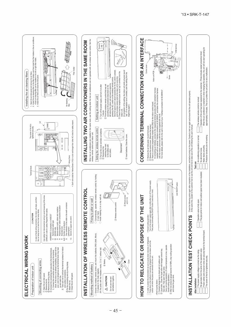
- 45 -
'13 • SRK-T-147
○
°○ ○ ○
•Forcedcoolingoperation
Turnon
thepowersupplyagainafterawhileafterturnoffthe
powersupply.
Thenpresscontinually
theON/OFFbutton5secondsormore.
○○
○ ○ ○ ○
CO
NC
ER
NIN
GT
ER
MIN
AL
CO
NN
EC
TIO
NF
OR
AN
INT
ER
FA
CE
Rem
ovetheairinletpanel,lidandfrontpanel.
Rem
ovethecontrolcover.(Rem
ovethescrew.)
Thereisaterminal(respectivelymarkedwith
CNS)fortheindoorcontrolboard.
Inconnectingan
interface,connecttotherespectiveterminalsecurelywith
theconnectionharness
suppliedwith
anoptional“InterfaceconnectionkitS
C-BIKN-E”andfasten
theconnectionharness
ontotheindoorcontrolbox
with
theclam
psuppliedwith
thekit.
Formoredetails,pleaserefertotheuser’smanualofyour“Interface
connectionkitS
C-BIKN-E”.
1 2 3
○ ○
○Uncover
thewireless
remotecontrol,andmount
thebatteries[R03
(AAA,Micro),
×2pieces]in
thebody
regularly.
(Fitthepoleswith
theindicationmarks,+
&-
withoutfail)
○Conventionally,operatethewireless
remotecontrolby
holding
inyour
hand.
○Avoid
installingiton
aclay
walletc.
Cover
CA
UT
ION
Woodscrews
ø3.5X16
Wireless
remotecontrol
Battery
INS
TA
LL
AT
ION
OF
WIR
EL
ES
SR
EM
OT
EC
ON
TR
OL
Mounting
meth
od
ofbattery
Fix
ing
topill
ar
or
wall
Donotuse
newand
oldbatteriestogether.
2
6
5
Reception
pip
Disconnect
TIMESETUPACL
Whentwoairconditionersareinstalledin
thesameroom
,usethissetting
whenthetwoairconditionersarenotoperated
with
onewireless
remotecontrol.Set
the
wireless
remotecontrolandindoor
unit.
INS
TA
LL
ING
TW
OA
IRC
ON
DIT
ION
ER
SIN
TH
ES
AM
ER
OO
M
Set
ting
the
wire
less
rem
ote
cont
rol
Pulloutthecoverandtake
outbatteries.
Disconnectthe
switching
linenext
tothebatterywith
wire
cutters.
Insertbatteries.Close
thecover.
1 2 3
Settin
gan
indoor
un
it
1 2 3
INS
TA
LL
AT
ION
TE
ST
CH
EC
KP
OIN
TS
Afterin
sta
llation
The
powersupplyvoltage
iscorrectastherating.
Nogasleaksfrom
thejointsoftheoperationvalve.
Pow
ercables
andcrossoverwiresaresecurelyfixed
totheterminalboard.
The
screwofthelid
istightened
securely.
Testru
n Airconditioningoperationisnormal.
Noabnormalnoise.
Waterdrains
smoothly.
Protectivefunctions
arenotw
orking.
The
wireless
remotecontrolisnormal.
Operationoftheunithasbeen
explainedtothecustom
er.(Three-minutes
restartpreventivetim
er)
Whentheairconditionerisrestartedorwhenchanging
theoperation,theunitwillnotstartoperatingfor
approximately3minutes.Thisistoprotectthe
unitanditisnota
malfunction.
Operationvalveisfully
open.
The
pipe
jointsforindoorandoutdoorpipeshave
been
insulated.
Check
thefollowingpointsagainaftercompletionoftheinstallation,andbeforeturningon
thepower.C
onductatestrunagainandensurethattheunitoperates
properly.
Atthe
sametim
e,explaintothecustom
erhowtousetheunitandhowtotake
careoftheunitfollowingtheuser’smanual.
Opentheairinletpanel.
Rem
ovethelid.
Rem
ovethewiring
clam
p.Connecttheconnectingwire
securelytotheterminalblock.
1)Connecttheconnectionwire
securelytotheterminal
block.Ifthewire
isnotaffixedcompletely,contactw
illbe
poor,and
itisdangerousas
theterminalblockmay
heat
upandcatchfire.
2)Takecarenottoconfusetheterminalnumbersforindoor
andoutdoorconnections.
Fixtheconnectingwire
bywiring
clam
p.Attach
thelid.
Close
theairinletpanel.
1 2 3 4 5 6 7
EL
EC
TR
ICA
LW
IRIN
GW
OR
K
CA
UT
ION
Incase
offaultywiring
connection,theindoorunitstops,andthen
therunlampturnson
andthetim
erlampblinks.
Use
cables
forinterconnectionwiring
toavoidlooseningofthewires.
CENELE
Ccode
forcables
Requiredfieldcables.
H05RNR4G
1.5(example)or245IEC57
HHarmonized
cabletype
05300/500volts
RNatural-and/orsynth,rubberwire
insulation
NPolychloroprene
rubberconductorsinsulation
RStrandedcore
4or5
Num
berofconductors
GOne
conductorofthecableistheearthconductor
(yellow/green)
1.5
Sectionofcopperwire
(mm
2 )
Pre
para
tion
ofin
door
unit
Mounting
ofconnecting
wires
Filter
holder
Air-cleaning
filter
Insta
lling
the
air-c
leanin
gfilters
1.Opentheairinletpanelandremovetheairfilters.
2.Installthe
air-cleaning
filterinthefilterholders,andthen
installthe
filterholdersintheairconditioner.
•Eachair-cleaning
filtercanbe
installedintheleftorrightfilterholder.
3.Installthe
airfiltersandclosetheinletpanel.
Turnoffthe
powersupply,and
turniton
after
1minute.
Pointthewireless
remotecontrolthatw
asset
accordingtotheproceduredescribed
onthe
leftside
attheindoorunitandsend
asignalby
pressing
theACLsw
itchon
thewireless
remotecontrol.
Sincethesignalissentinabout6
secondsafterthe
ACLsw
itchispressed,
pointthe
wireless
remotecontrolatthe
indoorunitforsom
etim
e.Check
thatthereceptionbuzzersound"pip"isem
itted
from
the
indoorunit.
Atcom
pletionofthesetting,the
indoorunitem
itsabuzzersound
"pip".(Ifnoreceptiontone
isem
itted,startthesetting
from
the
beginningagain.)
Connectcharge
hose
tocheckjointofoutdoorunit.
Liquidside
:Close
theliquidvalvewith
hexagonwrenchkey.
Gas
side
:Fullyopen
thegasvalve.
Carryoutcoolingoperation.(Ifindoortemperatureislow,operate
forced
coolingoperation.)
Afterlowpressuregaugebecome0.01MPa,stop
coolingoperation
andclosethegasvalve.
1 2 3
<How
topumpdown>
○Inordertoprotectthe
environm
ent,be
suretopumpdown(recoveryofrefrigerant).
○Pum
pdownisthemethodofrecoveringrefrigerantfromtheindoorunittothe
outdoorunitwhenthepipesareremoved
from
theunit.
HO
WT
OR
EL
OC
AT
EO
RD
ISP
OS
EO
FT
HE
UN
IT
UnitO
N/OFFbutton
IndoorunitPCB
Screw
CNSterminal
Controlcover
○①
②
③
○①
②
③
④
⑤
Terminalblock
13
2/N
Lid
The
screwofthelid
istightened
securely.
Wiring
Clamp
•Earthwire
shallbeYellow/Green
(Y/G)incolorandlongerthan
otherACwiresforsafetyreason.

- 46 -
'13 • SRK-T-147
INS
TA
LLA
TIO
NM
AN
UA
LFO
RO
UTD
OO
RU
NIT
RC
R012A
002
R4
10
AR
EF
RIG
ER
AN
TU
SE
D
•R
ead
the
“SA
FE
TY
PR
EC
AU
TIO
NS
”care
fully
first
ofall
and
str
ictly
follo
wit
during
the
insta
llation
work
inord
er
top
rote
ct
yours
elf.
•The
pre
cautionary
item
sm
entioned
belo
ware
dis
tinguis
hed
into
two
leve
ls,
and
.
:W
rong
insta
llatio
nw
ould
cause
serious
conseq
uences
such
as
inju
ries
or
death
.
:W
rong
insta
llatio
nm
ight
cause
serious
conseq
uences
dep
end
ing
on
circum
sta
nces.
Both
mentions
the
imp
ort
ant
item
sto
pro
tect
your
health
and
safe
tyso
str
ictly
follo
wth
em
by
any
means.
•B
esure
toconfir
mno
anom
aly
on
the
eq
uip
ment
by
com
mis
sio
nin
gafter
co
mp
lete
din
sta
llation
and
exp
lain
the
op
era
ting
meth
od
sas
well
as
the
main
tenance
meth
od
softh
iseq
uip
ment
toth
euser
accord
ing
toth
eow
ner’s
manual.
•K
eep
the
insta
llation
manualt
ogeth
er
with
ow
ner’s
manuala
ta
pla
ce
where
any
user
can
read
at
any
tim
e.
More
ove
rif
necessary
,ask
tohand
them
toa
new
user.
•For
insta
lling
qualif
ied
pers
onnel,
take
pre
cautions
inre
sp
ect
toth
em
selv
es
by
usin
gsuitab
lep
rote
ctive
clo
thin
g,gro
ves,etc
.,and
then
perf
orm
the
insta
llation
work
s.
•P
lease
pay
att
ention
no
tto
fall
dow
nth
eto
ols
,etc
.w
hen
insta
lling
the
unit
at
the
hig
hp
ositio
n.
•If
unusualn
ois
ecan
be
heard
during
op
era
tion,consult
the
deale
r.
•The
meanin
gs
of“M
ark
s”
used
here
are
show
nas
follo
ws:
•T
his
insta
lla
tio
nm
an
ua
ld
ea
lsw
ith
ou
tdo
or
un
its
an
dg
en
era
lin
sta
lla
tio
nsp
ec
ific
ati
on
so
nly
.F
or
ind
oo
ru
nit
s,re
fer
top
ag
e42
.
•W
he
nin
sta
llth
eu
nit
,b
esu
reto
ch
ec
kw
he
the
rth
ese
lec
tio
no
fin
sta
lla
tio
np
lac
e,
po
we
rsu
pp
lysp
ec
ific
ati
on
s,u
sa
ge
lim
ita
tio
n(p
ipin
gle
ng
th,h
eig
ht
dif
fere
nc
es
be
twe
en
ind
oo
ra
nd
ou
tdo
or
un
its,p
ow
er
su
pp
lyvo
lta
ge
an
de
tc.)
an
din
sta
lla
tio
nsp
ac
es.
SA
FE
TY
PR
EC
AU
TIO
NS
WA
RN
INGN
eve
rd
oit
und
er
any
circum
sta
nces.
Alw
ays
do
itaccord
ing
toth
ein
str
uction.
CA
UT
ION
WA
RN
ING
CA
UT
ION
WA
RN
ING
CA
UT
ION
•In
stall
ati
on
must
be
carr
ied
ou
tb
yth
equ
ali
fied
inst
all
er.
Ifyo
uin
stal
lthe
syst
emby
your
self,
itm
ayca
use
seri
ous
trou
ble
such
asw
ater
leak
s,el
ectr
icsh
ocks
,fir
ean
dpe
rson
alin
jury
,as
are
sult
ofa
syst
emm
alfu
nctio
n.D
ono
tca
rry
outt
hein
stal
latio
nan
dm
aint
enan
cew
ork
exce
ptth
eby
qual
ified
inst
alle
r.•
Inst
all
the
syst
em
infu
llacc
ord
ance
wit
hth
ein
stall
ati
on
ma
nual.
Inco
rrec
tins
talla
tion
may
caus
ebu
rsts
,per
sona
linj
ury,
wat
erle
aks,
elec
tric
shoc
ksan
dfir
e.•
Be
sure
touse
only
for
house
hold
an
dre
side
nce
.If
this
appl
ianc
eis
inst
alle
din
infe
rior
envi
ronm
ents
uch
asm
achi
nesh
opan
det
c.,
itca
nca
use
mal
func
tion.
•W
he
nin
stall
ing
insm
all
room
s,ta
kepre
venti
on
measu
res
not
toexc
eed
the
densi
tyli
mit
of
refr
igera
nt
inth
eeve
nt
of
leaka
ge,
refe
rred
by
the
form
ula
(acc
ord
ance
wit
hIS
O51
49).
Ifth
ede
nsity
ofre
frig
eran
texc
eeds
the
limit,
plea
seco
nsul
tthe
deal
eran
din
stal
lth
eve
ntila
tion
syst
em,o
ther
wis
ela
ckof
oxyg
enca
noc
cur,
whi
chca
nca
use
seri
ous
acci
dent
.•
Use
the
ori
gin
al
acc
ess
ori
es
an
dth
esp
eci
fied
com
ponents
for
inst
all
ati
on.
Ifpa
rts
othe
rth
anth
ose
pres
crib
edby
usar
eus
ed,I
tmay
caus
ew
ater
leak
s,el
ectr
icsh
ocks
,fir
ean
dpe
rson
alin
jury
.•
Inst
all
the
un
itin
alo
cati
on
wit
hgood
suppo
rt.
Uns
uita
ble
inst
alla
tion
loca
tions
can
caus
eth
eun
itto
fall
and
caus
em
ater
ial
dam
age
and
pers
onal
inju
ry.
•Ensu
reth
eu
nit
isst
able
when
inst
all
ed,
soth
at
itca
nw
ithst
and
eart
hquake
sand
stro
ng
win
ds.
Uns
uita
ble
inst
alla
tion
loca
tions
can
caus
eth
eun
itto
fall
and
caus
em
ater
ial
dam
age
and
pers
onal
inju
ry.
•V
ent
ilat
eth
ew
orki
ng
are
aw
ell
inth
eev
ent
ofre
frig
eran
tle
akag
edu
ring
inst
alla
tion
.If
the
refr
iger
antc
omes
into
cont
actw
ithna
ked
flam
es,p
oiso
nous
gas
ispr
oduc
ed.
•U
seth
epre
scri
bed
pip
es,
flare
nuts
and
tools
for
R410A
.U
sing
exis
ting
part
s(f
orR
22or
R40
7C)
can
caus
eth
eun
itfa
ilure
and
seri
ous
acci
dent
sdu
eto
burs
toft
here
frig
eran
tcir
cuit.
•Ti
ghte
nth
efl
are
nut
by
torq
ue
wre
nch
wit
hsp
eci
fied
meth
od.
Ifth
efla
renu
twer
etig
hten
edw
ithex
cess
torq
ue,t
his
may
caus
ebu
rsta
ndre
frig
eran
tlea
kage
afte
ra
long
peri
od.
•D
on
ot
open
the
opera
tion
valv
es
for
liquid
lin
ean
dg
as
line
unti
lco
mp
lete
dre
frig
era
nt
pip
ing
work
,a
irti
gh
tness
test
and
eva
cuati
on.
Ifth
eco
mpr
esso
ris
oper
ated
inst
ate
ofop
enin
gop
erat
ion
valv
esbe
fore
com
plet
edco
nnec
tion
ofre
frig
eran
tpip
ing
wor
k,ai
rca
nbe
suck
edin
tore
frig
eran
tci
rcui
t,w
hich
can
caus
ebu
stor
pers
onal
inju
rydu
eto
anom
alou
sly
high
pres
sure
inth
ere
frig
eran
t.•
The
elec
tric
alin
stal
lati
onm
ust
beca
rrie
dou
tby
the
qual
ifie
del
ectr
icia
nin
acco
rdan
cew
ith
“the
norm
for
elec
tric
alw
ork”
and
“nat
iona
lw
irin
gre
gula
tion
”,an
dth
esy
stem
mus
tbe
conn
ecte
dto
the
dedi
cate
dci
rcui
t.P
ower
supp
lyw
ithin
suffi
cien
tcap
acity
and
inco
rrec
tfun
ctio
ndo
neby
impr
oper
wor
kca
nca
use
elec
tric
shoc
ksan
dfir
e.•
Be
sure
tosh
ut
off
the
pow
er
befo
rest
art
ing
ele
ctri
cal
work
.Fa
ilure
tosh
utof
fthe
pow
erca
nca
use
elec
tric
shoc
ks,u
nitf
ailu
reor
inco
rrec
tfu
nctio
nof
equi
pmen
t.•
Be
sure
touse
the
cab
les
confo
rmed
tosa
fety
stan
dard
and
cab
leam
paci
tyfo
rpow
er
dis
trib
uti
on
work
.U
ncon
form
able
cabl
esca
nca
use
elec
tric
leak
,ano
mal
ous
heat
prod
uctio
nor
fire.
•This
appli
ance
mu
stbe
conne
cted
tom
ain
pow
er
supply
by
means
of
a
circ
uit
bre
ake
ror
swit
ch(f
use
:20A
)w
ith
aco
nta
ctse
para
tion
of
at
least
3m
m.
•A
rrange
the
wir
ing
inth
eco
ntr
ol
box
soth
at
itca
nnot
be
push
ed
up
furt
her
into
the
bo
x.In
stall
the
serv
ice
panel
corr
ect
ly.
Inco
rrec
tins
talla
tion
may
resu
ltin
over
heat
ing
and
fire.
•U
seth
epre
scri
bed
cable
sfo
rele
ctri
cal
connect
ion,
tigh
ten
the
cable
sse
cure
lyin
term
inal
blo
ckand
reli
eve
the
cable
sco
rrect
lyto
pre
vent
ove
rloadin
gth
ete
rmin
al
blo
cks.
Loos
eco
nnec
tions
orca
ble
mou
ntin
gsca
nca
use
anom
alou
she
atpr
oduc
tion
orfir
e.•
Be
sure
tofi
xup
the
serv
ice
pane
ls.
Inco
rrec
tfix
ing
can
caus
eel
ectr
icsh
ocks
orfir
edu
eto
intr
usio
nof
dust
orw
ater
.•
Be
sure
tosw
itch
off
the
pow
er
supply
inth
eeve
nt
of
inst
all
ati
on,
insp
ect
ion
or
serv
icin
g.
Ifth
epo
wer
supp
lyis
nots
huto
ff,th
ere
isa
risk
ofel
ectr
icsh
ocks
,uni
tfai
lure
orpe
rson
alin
jury
due
toth
eun
expe
cted
star
toff
an.
•S
top
the
com
pre
ssor
befo
rere
mo
ving
the
pip
eaft
er
shutt
ing
the
opera
tion
valv
eon
pum
pdo
wn
work
.If
the
pipe
isre
mov
edw
hen
the
com
pres
sor
isin
oper
atio
nw
ithth
eop
erat
ion
valv
eop
en,a
irw
ould
bem
ixed
inth
ere
frig
erat
ion
circ
uita
ndit
coul
dca
use
expl
osio
nan
din
juri
esdu
eto
abno
rmal
high
pres
sure
inth
eco
olin
gcy
cle.
•O
nly
use
pre
scri
bed
opti
on
al
part
s.The
inst
all
ati
on
mu
stbe
carr
ied
out
by
the
quali
fie
din
stall
er.
Ifyo
uin
stal
lthe
syst
emby
your
self,
itca
nca
use
seri
ous
trou
ble
such
asw
ater
leak
s,el
ectr
icsh
ocks
,fir
e.•
Be
sure
tow
ear
pro
tect
ive
goggle
sand
glo
ves
whil
ea
tw
ork
.•
Eart
hle
aka
ge
bre
ake
rm
ust
be
inst
all
ed.
Ifth
eea
rth
leak
age
brea
ker
isno
tins
talle
d,it
can
caus
eel
ectr
icsh
ocks
.
•Ensu
reth
at
no
air
ente
rsin
the
refr
igera
nt
circ
uit
when
the
unit
isin
stall
ed
and
rem
ove
d.
Ifai
ren
ters
inth
ere
frig
eran
tcir
cuit,
the
pres
sure
inth
ere
frig
eran
tcir
cuit
beco
mes
too
high
,whi
chca
nca
use
burs
tand
pers
onal
inju
ry.
•D
ono
tpro
cess
ing,
splic
eth
epo
wer
cord
,ors
hare
aso
cket
with
othe
rpow
erpl
ugs.
This
may
caus
efir
eor
elec
tric
shoc
kdu
eto
defe
ctin
gco
ntac
t,de
fect
ing
insu
latio
nan
dov
er-c
urre
ntet
c.
•D
on
ot
bundli
ng,
win
din
gor
pro
cess
ing
for
the
pow
er
cord
.O
r,do
not
defo
rmin
gth
epow
er
plu
gdue
totr
ead
it.
This
may
caus
efir
eor
heat
ing.
•D
on
ot
run
the
unit
wit
hre
move
dpan
els
or
pro
tect
ions.
Touc
hing
rota
ting
equi
pmen
ts,h
otsu
rfac
esor
high
volta
gepa
rts
can
caus
epe
rson
alin
jury
due
toen
trap
men
t,bu
rnor
elec
tric
shoc
ks.
•D
onot
perf
orm
any
change
of
pro
tect
ive
devi
ceit
self
or
its
setu
pco
ndit
ion.
The
forc
edop
erat
ion
bysh
ort-
circ
uitin
gpr
otec
tive
devi
ceof
pres
sure
switc
han
dte
mpe
ratu
reco
ntro
ller
orth
eus
eof
non
spec
ified
com
pone
ntca
nca
use
fire
orbu
rst.
(
2)
In
sta
lla
tio
n o
f o
utd
oo
r u
nit
M
od
els
SR
C6
3Z
MA
-S,
71
ZM
A-S
, 8
0Z
MA
-S
- 47 -
'13 • SRK-T-147
Accesso
ries
for
ou
tdo
or
un
it
•M
od
eln
am
eand
pow
er
sourc
e
•R
efr
igera
nt
pip
ing
length
•P
ipin
g,w
irin
gand
mis
cella
neous
sm
all
part
s
•In
do
or
unit
insta
llation
manual
Necessary
too
lsfo
rth
ein
sta
llati
on
wo
rkW
rench
key
(Hexagon)[4
m/m
]
Vacuum
pum
p
Vacuum
pum
pad
ap
ter
(Anti-r
eve
rse
flow
typ
e)
(Desig
ned
sp
ecifi
cally
for
R410A
)
Gauge
manifo
ld(D
esig
ned
sp
ecifi
cally
for
R410
A)
Charg
ehose
(Desig
ned
sp
ecifi
cally
for
R410A
)
Fla
ring
tools
et
(Desig
ned
sp
ecifi
cally
for
R410A
)
Gas
leak
dete
cto
r(D
esig
ned
sp
ecifi
cally
for
R4
10A
)
Gauge
for
pro
jection
ad
justm
ent
(Used
when
flare
ism
ad
eb
yusin
gconve
ntionalf
lare
tool)
9 10
11
12
13
14
15
16
Plu
shead
ed
drive
r
Knife
Saw
Tap
em
easure
Ham
mer
Sp
anner
wre
nch
Torq
ue
wre
nch
[14
.0~
82.0
N·m
(1.4~
8.2
kgf·m
)]
Hole
core
drill
(65m
min
dia
mete
r)
1 2 3 4 5 6 7 8
Gro
mm
et
(Heat
pum
pty
pe
only
)
Dra
inelb
ow
(Heat
pum
pty
pe
only
)
Q’t
y
2 1
1 2
Op
tio
np
art
s
Sealin
gp
late
Sle
eve
Inclin
ation
pla
te
Putt
y
Dra
inhose
(exte
nsio
nhose)
Pip
ing
cove
r
(for
insula
tion
ofconnection
pip
ing)
Q’t
y
1 1 1 1 1 1
Ch
ec
kb
efo
rein
sta
lla
tio
nw
ork
a b c d e f
CA
UT
ION
•C
arr
you
tth
ee
lect
rica
lw
ork
for
gro
un
dle
ad
wit
hca
re.
Do
notc
onne
ctth
egr
ound
lead
toth
ega
slin
e,w
ater
line,
light
ning
cond
ucto
ror
tele
phon
elin
e’s
grou
ndle
ad.I
ncor
rect
grou
ndin
gca
nca
use
unit
faul
tssu
chas
elec
tric
shoc
ksdu
eto
shor
t-ci
rcui
ting.
•U
seth
eci
rcu
itb
reake
rfo
rall
po
leco
rrect
capa
city
.C
ircu
itbre
ake
rsh
ould
be
the
one
that
dis
connect
all
pole
sunder
ove
rcu
rren
t.U
sing
the
inco
rrec
tcir
cuit
brea
ker,
itca
nca
use
the
unit
mal
func
tion
and
fire.
•In
stall
isola
tor
or
dis
connect
swit
chon
the
pow
er
supp
lyw
irin
gin
acc
ord
an
cew
ith
the
loca
lco
des
and
reg
ula
tio
ns.
The
isol
ator
shou
ldbe
lock
edin
OFF
stat
ein
acco
rdan
cew
ithEN
6020
4-1.
•A
fter
mai
nten
ance
,al
lw
irin
g,w
irin
gti
esan
dth
eli
ke,
shou
ldbe
retu
rned
toth
eir
orig
inal
stat
ean
dw
irin
gro
ute,
and
the
nece
ssar
ycl
eara
nce
from
all
met
alpa
rts
shou
ldbe
secu
red.
•S
ecu
rea
space
for
inst
all
ati
on,
insp
ect
ion
and
main
tenance
speci
fied
inth
em
anual.
Insu
ffici
ents
pace
can
resu
ltin
acci
dent
such
aspe
rson
alin
jury
due
tofa
lling
from
the
inst
alla
tion
plac
e.
•Ta
keca
rew
he
nca
rryi
ng
the
unit
by
hand
.If
the
unit
wei
ghts
mor
eth
an20
kg,i
tmus
tbe
carr
ied
bytw
oor
mor
epe
rson
s.D
ono
tcar
ryby
the
plas
ticst
raps
,alw
ays
use
the
carr
yha
ndle
whe
nca
rryi
ngth
eun
itby
hand
.Use
glov
esto
min
imiz
eth
eri
skof
cuts
byth
eal
umin
umfin
s.•
Dis
pose
of
any
pa
ckin
gm
ate
rials
corr
ect
ly.
Any
rem
aini
ngpa
ckin
gm
ater
ials
can
caus
epe
rson
alin
jury
asit
cont
ains
nails
and
woo
d.A
ndto
avoi
dda
nger
ofsu
ffoca
tion,
besu
reto
keep
the
plas
ticw
rapp
eraw
ayfr
omch
ildre
nan
dto
disp
ose
afte
rte
arit
up.
•B
esu
reto
insu
late
the
refr
ige
rant
pip
es
soas
not
toco
nde
nse
the
am
bie
nt
air
mois
ture
on
the
m.
Insu
ffici
enti
nsul
atio
nca
nca
use
cond
ensa
tion,
whi
chca
nle
adto
moi
stur
eda
mag
eon
the
ceili
ng,f
loor
,fur
nitu
rean
dan
yot
her
valu
able
s.
•W
hen
perf
orm
the
air
cond
itio
ner
oper
ati
on
(coo
ling
or
dryi
ngope
rati
on)
inw
hich
vent
ilat
oris
inst
alle
din
the
room
.In
this
case
,us
ing
the
air
cond
itio
ner
inpa
rall
elw
ith
the
vent
ilato
r,th
ere
isth
epos
sibil
ity
that
drai
nw
ate
rm
ayba
ckfl
ow
inacc
orda
nce
wit
hth
ero
omla
pse
into
the
nega
tive
press
ure
statu
s.The
refo
re,
set
upth
eop
enin
gpor
tsu
chas
inco
rpor
ate
the
air
into
the
room
that
may
appr
opr
iate
tove
nti
lati
on(F
orex
ampl
e;
Open
the
door
ali
ttle
).In
add
itio
n,
just
asabo
ve,
sose
tup
the
open
ing
port
ifth
ero
omla
pse
into
neg
ati
vepr
essu
rest
atus
due
tore
gist
er
ofth
ew
ind
for
the
high
rise
apar
tmen
tet
c.
•D
on
ot
inst
all
the
un
itin
the
loca
tio
ns
list
ed
be
low
.•
Loca
tions
whe
reca
rbon
fiber
,met
alpo
wde
ror
any
pow
der
isflo
atin
g.•
Loca
tions
whe
rean
ysu
bsta
nces
that
can
affe
ctth
eun
itsu
chas
sulp
hide
gas,
chlo
ride
gas,
acid
and
alka
line
can
occu
r.•
Vehi
cles
and
ship
s.•
Loca
tions
whe
reco
smet
icor
spec
ials
pray
sar
eof
ten
used
.•
Loca
tions
with
dire
ctex
posu
reof
oilm
ista
ndst
eam
such
aski
tche
nan
dm
achi
nepl
ant.
•Lo
catio
nsw
here
any
mac
hine
sw
hich
gene
rate
high
freq
uenc
yha
rmon
ics
are
used
.•
Loca
tions
with
salty
atm
osph
eres
such
asco
astli
nes.
•Lo
catio
nsw
ithhe
avy
snow
(Ifi
nsta
lled,
besu
reto
prov
ide
base
flam
ean
dsn
owho
odm
entio
ned
inth
em
anua
l).
•Lo
catio
nsw
here
the
unit
isex
pose
dto
chim
ney
smok
e.•
Loca
tions
athi
ghal
titud
e(m
ore
than
1000
mhi
gh).
•Lo
catio
nsw
itham
mon
icat
mos
pher
es.
•Lo
catio
nsw
here
heat
radi
atio
nfr
omot
her
heat
sour
ceca
naf
fect
the
unit.
•Lo
catio
nsw
ithou
tgoo
dai
rci
rcul
atio
n.•
Loca
tions
with
any
obst
acle
sw
hich
can
prev
enti
nlet
and
outle
tair
ofth
eun
it.•
Loca
tions
whe
resh
ortc
ircu
itof
air
can
occu
r(i
nca
seof
mul
tiple
units
inst
alla
tion)
.•
Loca
tions
whe
rest
rong
air
blow
sag
ains
tthe
air
outle
tofo
utdo
orun
it.•
Loca
tions
whe
reso
met
hing
loca
ted
abov
eth
eun
itco
uld
fall.
Itca
nca
use
rem
arka
ble
decr
ease
inpe
rfor
man
ce,c
orro
sion
and
dam
age
ofco
mpo
nent
s,m
alfu
nctio
nan
dfir
e.
•D
on
ot
inst
all
the
ou
tdo
or
un
itin
the
loca
tio
ns
list
ed
be
low
.•
Loca
tions
whe
redi
scha
rged
hota
iror
oper
atin
gso
und
ofth
eou
tdoo
run
itca
nbo
ther
neig
hbor
hood
.•
Loca
tions
whe
reou
tleta
irof
the
outd
oor
unit
blow
sdi
rect
lyto
anan
imal
orpl
ants
.The
outle
tair
can
affe
ctad
vers
ely
toth
epl
ante
tc.
•Lo
catio
nsw
here
vibr
atio
nca
nbe
ampl
ified
and
tran
smitt
eddu
eto
insu
ffici
ent
stre
ngth
ofst
ruct
ure.
•Lo
catio
nsw
here
vibr
atio
nan
dop
erat
ion
soun
dge
nera
ted
byth
eou
tdoo
run
itca
naf
fect
seri
ousl
y(o
nth
ew
allo
rat
the
plac
ene
arbe
dro
om).
•Lo
catio
nsw
here
aneq
uipm
enta
ffect
edby
high
harm
onic
sis
plac
ed(T
Vse
tor
radi
ore
ceiv
eris
plac
edw
ithin
1m).
•Lo
catio
nsw
here
drai
nage
cann
otru
nof
fsaf
ely.
Itca
naf
fect
surr
ound
ing
envi
ronm
enta
ndca
use
acl
aim
.•
Do
no
tin
sta
llth
eu
nit
ne
ar
the
loca
tio
nw
he
rele
aka
ge
of
com
bu
stib
leg
ase
sca
no
ccu
r.If
leak
edga
ses
accu
mul
ate
arou
ndth
eun
it,it
can
caus
efir
e.•
Do
noti
nsta
llth
eun
itw
here
corr
osiv
ega
s(s
uch
assu
lfur
ous
acid
gas
etc.
)or
com
bust
ible
gas
(suc
has
thin
ner
and
petr
oleu
mga
ses)
can
accu
mul
ate
orco
llec
t,or
whe
revo
lati
leco
mbu
stib
lesu
bsta
nces
are
hand
led.
Cor
rosi
vega
sca
nca
use
corr
osio
nof
heat
exch
ange
r,br
eaka
geof
plas
ticpa
rts
and
etc.
And
com
bust
ible
gas
can
caus
efir
e.•
Do
no
tin
sta
lln
or
use
the
syst
em
clo
seto
the
eq
uip
me
nt
tha
tg
en
era
tes
ele
ctro
ma
gn
eti
cfi
eld
so
rh
igh
fre
qu
en
cyh
arm
on
ics.
Equi
pmen
tsuc
has
inve
rter
s,st
andb
yge
nera
tors
,med
ical
high
freq
uenc
yeq
uipm
ents
and
tele
com
mun
icat
ion
equi
pmen
tsca
naf
fect
the
syst
em,a
ndca
use
mal
func
tions
and
brea
kdow
ns.T
hesy
stem
can
also
affe
ctm
edic
aleq
uipm
enta
ndte
leco
mm
unic
atio
neq
uipm
ent,
and
obst
ruct
itsfu
nctio
nor
caus
eja
mm
ing.
•D
on
ot
inst
all
the
ou
tdo
or
un
itin
alo
cati
on
wh
ere
inse
cts
an
dsm
all
an
ima
lsca
nin
ha
bit
.In
sect
san
dsm
alla
nim
als
can
ente
rth
eel
ectr
icpa
rts
and
caus
eda
mag
eor
fire.
Inst
ruct
the
user
toke
epth
esu
rrou
ndin
gscl
ean.
•D
ono
tus
eth
eba
sefl
ame
for
outd
oor
unit
whi
chis
corr
oded
orda
mag
eddu
eto
long
peri
ods
ofop
erat
ion.
Usi
ngan
old
and
dam
age
base
flam
eca
nca
use
the
unit
falli
ngdo
wn
and
caus
epe
rson
alin
jury
.•
Do
no
tu
sea
ny
ma
teri
als
oth
er
tha
na
fuse
wit
hth
eco
rre
ctra
tin
gin
the
loca
tio
nw
he
refu
ses
are
tob
eu
sed
.C
onne
ctin
gth
eci
rcui
twith
copp
erw
ire
orot
her
met
alth
read
can
caus
eun
itfa
ilure
and
fire.
•D
on
ot
tou
cha
ny
bu
tto
ns
wit
hw
et
ha
nd
s.It
can
caus
eel
ectr
icsh
ocks
.•
Do
not
touch
any
refr
igera
nt
pip
es
wit
hyo
ur
hands
when
the
syst
em
isin
opera
tion.
Dur
ing
oper
atio
nth
ere
frig
eran
tpip
esbe
com
eex
trem
ely
hoto
rex
trem
ely
cold
depe
ndin
gth
eop
erat
ing
cond
ition
,and
itca
nca
use
burn
inju
ryor
fros
tinj
ury.
•D
on
ot
tou
chth
esu
ctio
no
ra
lum
inu
mfi
no
nth
eo
utd
oo
ru
nit
.Th
ism
ayca
use
inju
ry.
•D
on
ot
pu
ta
nyt
hin
go
nth
eo
utd
oo
ru
nit
an
do
pe
rati
ng
un
it.
This
may
caus
eda
mag
eth
eob
ject
sor
inju
rydu
eto
falli
ngto
the
obje
ct.
•D
on
ot
use
the
un
itfo
rsp
eci
al
pu
rpo
ses
such
as
sto
rin
gfo
od
s,co
oli
ng
pre
cisi
on
inst
rum
en
tsa
nd
pre
serv
ati
on
of
an
ima
ls,
pla
nts
or
art
.•
Do
no
tcl
ea
nu
pth
eu
nit
wit
hw
ate
r.
No
tab
ilia
as
au
nit
de
sig
ne
dfo
rR
41
0A
•D
on
ot
use
any
refr
iger
ant
oth
erth
anR
410
A.
R41
0A
will
rise
top
ress
ure
abou
t1
.6ti
mes
hig
her
than
that
of
aco
nve
nti
on
alre
frig
eran
t.A
cylin
der
con
tain
ing
R4
10
Ah
asa
pin
kin
dic
atio
nm
ark
on
the
top
.•
Aun
itd
esig
ned
for
R4
10A
has
adop
ted
ad
iffe
rent
size
ind
oo
ru
nit
op
erat
ion
valv
ech
arg
epo
rtan
da
dif
fere
nt
size
chec
kjo
int
pro
vided
inth
eu
nit
top
reve
nt
the
char
gin
go
fa
wro
ng
refr
iger
ant
by
mis
take
.T
he
pro
cess
edd
imen
sio
no
fth
efl
ared
par
tof
are
frig
eran
tp
ipe
and
afl
are
nu
t’s
par
alle
lsi
de
mea
sure
men
th
ave
also
bee
nal
tere
dto
rais
est
reng
thag
ain
stpre
ssu
re.
Acc
ord
ing
ly,
you
are
requ
ired
toar
ran
ge
ded
icat
edR
41
0A
tools
liste
din
the
tab
leo
nth
ele
ftbef
ore
inst
allin
go
rse
rvic
ing
this
un
it.
•D
on
ot
use
ach
arg
ecy
lind
er.
The
use
of
ach
arg
ecy
lind
erw
illca
use
the
refr
iger
ant
com
po
siti
on
toch
ange,
wh
ich
resu
lts
inper
form
ance
deg
radat
ion
.•
Inch
arg
ing
refr
iger
ant,
alw
ays
take
ito
ut
from
acy
lind
erin
the
liqu
idp
has
e.•
All
ind
oo
ru
nit
sm
ust
be
mo
del
sd
esig
ned
excl
usi
vely
for
R41
0A
.C
hec
kco
nn
ecta
ble
ind
oo
ru
nit
mo
del
sin
aca
talo
g,
etc.
(Aw
rong
ind
oo
ru
nit
,if
con
nec
ted
into
the
syst
em,
will
imp
air
pro
per
syst
emo
per
atio
n)
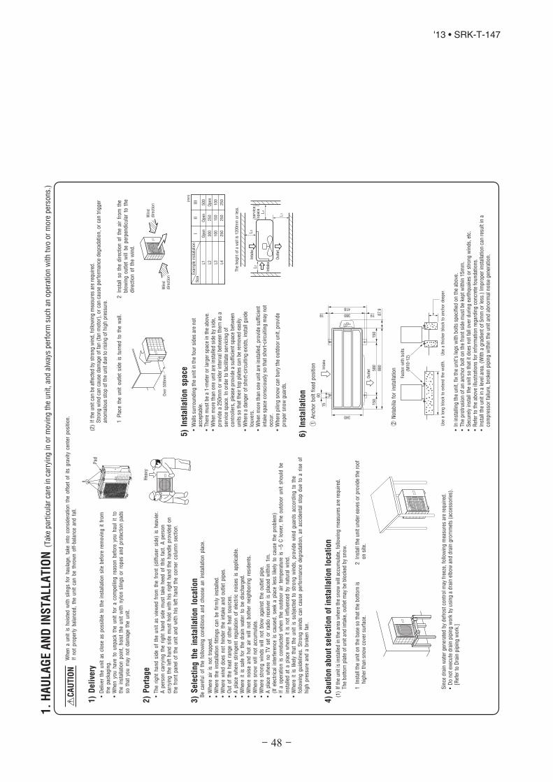
- 48 -
'13 • SRK-T-147
1.
HA
UL
AG
EA
ND
INS
TA
LLA
TIO
N(T
ake
par
ticu
lar
care
inca
rryi
ng
ino
rm
ovi
ng
the
unit,
and
alw
ays
per
form
such
ano
per
atio
nw
ith
two
or
mo
reper
son
s.)
Inta
ke
The
hei
ght
of
aw
all
is1200m
mor
less
.
(serv
ice
spac
e)
Inta
ke
Outl
et
Fast
enw
ith
bolts
(M10-1
2) U
sea
thic
ker
blo
ckto
anch
or
dee
per
.U
sea
long
blo
ckto
exte
nd
the
wid
th.
CA
UT
ION
Wh
ena
un
itis
ho
iste
dw
ith
slin
gs
for
hau
lag
e,ta
kein
toco
nsi
der
atio
nth
eo
ffse
tof
its
gra
vity
cente
rpo
sitio
n.
Ifn
ot
pro
per
lybal
ance
d,
the
unit
can
be
thro
wn
off
-bal
ance
and
fall.
1)
De
live
ry
2)
Po
rta
ge
3)
Se
lect
ing
the
inst
all
ati
on
loca
tio
n
5)
Inst
all
ati
on
spa
ce
L3
L2
L4
L1
Exa
mple
inst
alla
tion
Siz
e
L1
L2
L3
L4
Open
300
100
250
Open
250
150
250
500
Open
100
250(m
m)
III
III
Hea
vy
6)
Inst
all
ati
on
Pad
Ove
r500m
m
•D
eliv
erth
eu
nit
ascl
ose
aspo
ssib
leto
the
inst
alla
tio
nsi
teb
efo
rere
mo
ving
itfr
om
the
pac
kagin
g.
•W
hen
you
hav
eto
unp
ack
the
unit
for
aco
mp
ellin
gre
aso
nb
efo
reyo
uh
aul
itto
the
inst
alla
tio
np
oin
t,h
ois
tth
eu
nit
wit
hn
ylon
slin
gs
or
rop
esan
dp
rote
ctio
npad
sso
that
you
may
not
dam
age
the
un
it.
•T
he
rig
ht
han
dsi
de
of
the
un
itas
view
edfr
om
the
fro
nt
(dif
fuse
rsi
de)
ishea
vier
.A
per
son
carr
ying
the
rig
ht
han
dsi
de
mu
stta
keh
eed
of
this
fact
.A
per
son
carr
yin
gth
ele
fth
and
side
must
ho
ldw
ith
his
rig
ht
han
dth
eh
and
lep
rovi
ded
on
the
fro
nt
pan
elof
the
unit
and
wit
hhis
left
han
dth
eco
rner
colu
mn
sect
ion
.
(1)
Ifth
eu
nit
isin
stal
led
inth
ear
eaw
her
eth
esn
ow
will
accu
mu
late
,fo
llow
ing
mea
sure
sar
ere
qu
ired
.T
he
bott
om
pla
teof
un
itan
din
take
,o
utl
etm
ayb
eb
lock
edb
ysn
ow
.
1In
stal
lth
eu
nit
on
the
bas
eso
that
the
bo
ttom
ish
igh
erth
ansn
ow
cove
rsu
rfac
e.
Sin
ced
rain
wat
ergen
erat
edb
ydef
rost
con
tro
lmay
free
ze,
follo
win
gm
easu
res
are
requ
ired
.•
Do
not
exec
ute
dra
inp
ipin
gw
ork
by
usi
ng
adra
inel
bo
wan
ddra
ing
rom
met
s(a
cces
sori
es).
[Ref
erto
Dra
inp
ipin
gw
ork
.]
2In
stal
lth
eu
nit
und
erea
ves
or
pro
vid
eth
ero
of
on
site
.
Be
care
ful
of
the
follo
win
gco
ndit
ion
san
dch
oo
sean
inst
alla
tio
np
lace
.
•W
her
eai
ris
not
trap
ped
.•
Wh
ere
the
inst
alla
tio
nfi
ttin
gs
can
be
firm
lyin
stal
led
.•
Wh
ere
win
ddo
esn
ot
hin
der
the
inta
kean
do
utl
etp
ipes
.•
Out
of
the
hea
tra
ng
eof
oth
erh
eat
sou
rces
.•
Ap
lace
wher
est
rin
gen
tre
gula
tio
no
fel
ectr
icn
ois
esis
applic
able
.•
Wh
ere
itis
safe
for
the
dra
inw
ater
tobe
dis
char
ged
.•
Wh
ere
nois
ean
dh
ot
air
will
no
tbo
ther
nei
gh
bo
ring
resi
den
ts.
•W
her
esn
ow
will
no
tac
cum
ula
te.
•W
her
est
ron
gw
ind
sw
illn
ot
blo
wag
ainst
the
outl
etp
ipe.
•A
pla
cew
her
en
oT
Vse
to
rra
dio
rece
iver
isp
lace
dw
ith
in1
m.
(If
elec
tric
alin
terf
eren
ceis
cau
sed
,se
eka
pla
cele
sslik
ely
toca
use
the
pro
ble
m)
•If
ao
per
atio
nis
cond
uct
edw
hen
the
outd
oo
rai
rte
mper
ature
is–
5C
low
er,
the
ou
tdoo
ru
nit
sho
uld
be
inst
alle
dat
ap
lace
wh
ere
itis
no
tin
flu
ence
db
yn
atu
ral
win
d.
•W
her
eit
islik
ely
that
the
un
itis
subje
cted
tost
rong
win
ds,
pro
vide
win
dgu
ard
sac
cord
ing
toth
efo
llow
ing
gu
idel
ines
.S
tron
gw
ind
sca
nca
use
per
form
ance
deg
rad
atio
n,
anac
cid
enta
lst
op
du
eto
ari
seo
fh
igh
pre
ssu
rean
da
bro
ken
fan.
4)
Ca
uti
on
ab
out
sele
ctio
no
fin
sta
lla
tio
nlo
cati
on
•W
alls
surr
ou
nd
ing
the
un
itin
the
fou
rsi
des
are
no
tac
cep
table
.•
Th
ere
must
be
a1
-met
eror
larg
ersp
ace
inth
eab
ove
.•
Wh
enm
ore
than
on
eu
nit
are
inst
alle
dsi
de
by
sid
e,pro
vid
ea
25
0m
mo
rw
ider
inte
rval
bet
wee
nth
emas
ase
rvic
esp
ace.
Ino
rder
tofa
cilit
ate
serv
icin
go
fco
ntr
olle
rs,
ple
ase
pro
vid
ea
suff
icie
nt
spac
eb
etw
een
un
its
soth
atth
eir
top
pla
tes
can
be
rem
ove
dea
sily
.•
Wh
ere
ad
anger
of
sho
rt-c
ircu
itin
gex
ists
,in
stal
lguid
elo
uve
rs.
•W
hen
mo
reth
ano
ne
un
itar
ein
stal
led
,p
rovi
de
suff
icie
nt
inta
kesp
ace
con
scio
usl
yso
that
sho
rt-c
ircu
itin
gm
ayn
ot
occ
ur.
•W
her
ep
ilin
gsn
ow
can
bu
ryth
eo
utd
oo
ru
nit
,p
rovi
de
pro
per
sno
wg
uar
ds.
•In
inst
allin
gth
eu
nit
,fi
xth
eu
nit
’sle
gs
wit
hb
olt
ssp
ecif
ied
on
the
abo
ve.
•Th
ep
rotr
usi
on
of
anan
cho
rb
olt
on
the
fro
nt
sid
em
ust
be
kep
tw
ith
in1
5m
m.
•S
ecu
rely
inst
allt
he
un
itso
that
itd
oes
no
tfa
llove
rd
uri
ng
eart
hq
uak
esor
stro
ng
win
ds,
etc.
•R
efer
toth
eab
ove
illu
stra
tio
ns
for
info
rmat
ion
regar
din
gco
ncr
ete
fou
nd
atio
ns.
•In
stal
lth
eu
nit
ina
leve
lare
a.(W
ith
ag
rad
ient
of
5m
mo
rle
ss.)
Imp
rop
erin
stal
lati
on
can
resu
ltin
aco
mp
ress
or
failu
re,
bro
ken
pip
ing
wit
hin
the
un
itan
dab
no
rmal
nois
eg
ener
atio
n.
1A
nch
or
bo
ltfi
xed
po
siti
on
2N
ota
bili
afo
rin
stal
lati
on
(2)
Ifth
eu
nit
can
be
affe
cted
by
stro
ng
win
d,
follo
win
gm
easu
res
are
req
uir
ed.
Str
on
gw
ind
can
cau
sed
amag
eof
fan
(fan
mo
tor)
,o
rca
nca
use
per
form
ance
deg
rad
atio
n,
or
can
trig
ger
ano
mal
ous
stop
of
the
unit
du
eto
risi
ng
of
hig
hpre
ssu
re.
1P
lace
the
un
itou
tlet
sid
eis
turn
edto
the
wal
l.2
Inst
all
soth
ed
irec
tio
no
fth
eai
rfr
om
the
blo
win
go
utl
etw
illb
ep
erpen
dic
ula
rto
the
dir
ecti
on
of
the
win
d.
Win
ddir
ection
Win
ddir
ecti
on
60
580
340
19 380
418
19
880
87.9
15 150
150
Inta
ke
Outlet
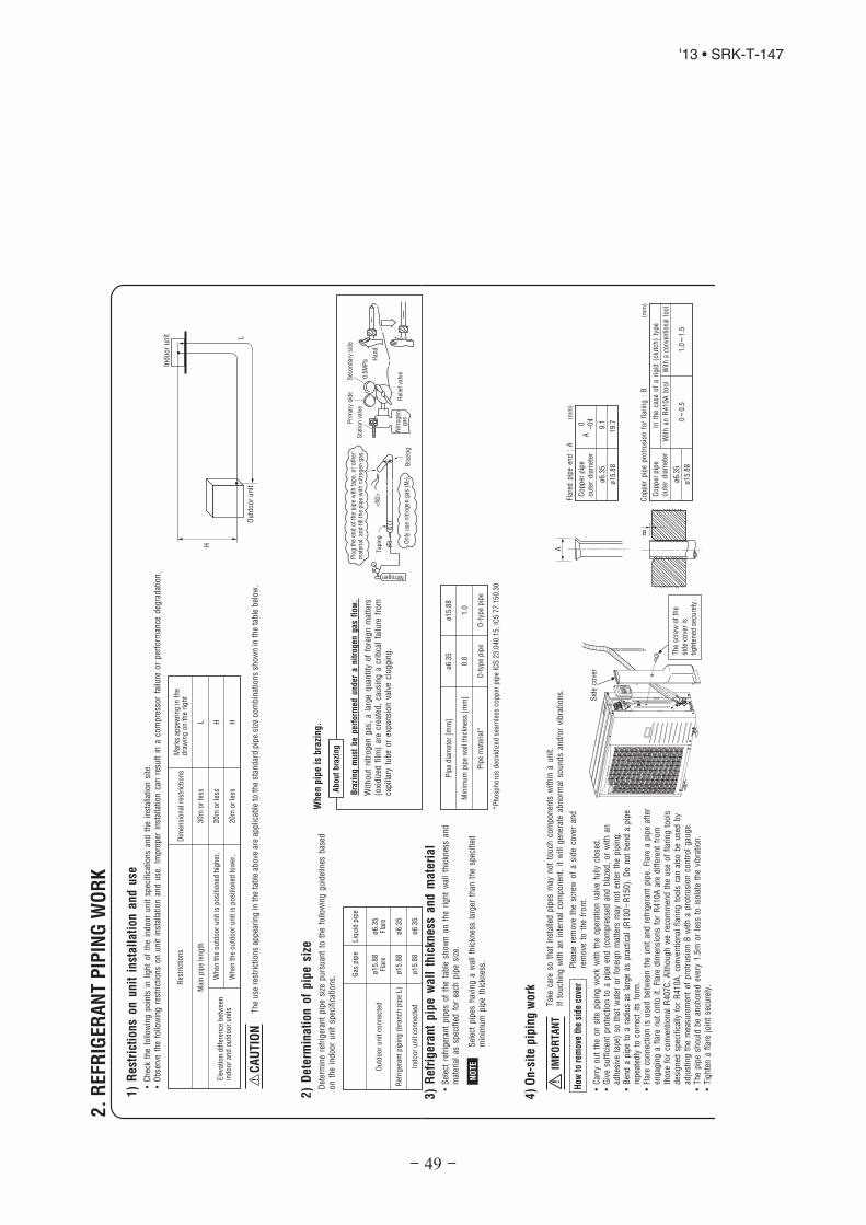
- 49 -
'13 • SRK-T-147
Det
erm
ine
refr
iger
ant
pip
esi
zep
urs
uan
tto
the
follo
win
gg
uid
elin
esb
ased
on
the
ind
oo
ru
nit
spec
ific
atio
ns.
Wit
hou
tn
itro
gen
gas
,a
larg
eq
uan
tity
of
fore
ign
mat
ters
(oxi
diz
edfi
lm)
are
crea
ted
,ca
usi
ng
acr
itic
alfa
ilure
fro
mca
pill
ary
tube
or
expan
sio
nva
lve
clo
gg
ing
.
2.
REF
RIG
ER
AN
TP
IPIN
GW
OR
K
1)
Re
stri
ctio
ns
on
un
itin
sta
lla
tion
an
du
se
2)
De
term
ina
tio
no
fp
ipe
size
L H HL
H
Outd
oor
un
it
Indo
or
unit
Th
eu
sere
stri
ctio
ns
app
eari
ng
inth
eta
ble
abo
vear
eap
plic
able
toth
est
and
ard
pip
esi
zeco
mbin
atio
ns
sho
wn
inth
eta
ble
bel
ow
.
Res
tric
tio
ns
Mar
ksap
pea
rin
gin
the
dra
win
go
nth
eri
gh
t
Mai
np
ipe
len
gth
Wh
enth
eo
utd
oo
ru
nit
isp
osi
tio
ned
hig
her
,
Wh
enth
eo
utd
oo
ru
nit
isp
osi
tio
ned
low
er,
Ele
vatio
nd
iffe
ren
ceb
etw
een
ind
oo
ran
do
utd
oo
ru
nit
s
Plu
gth
een
dof
the
pip
ew
ith
tape,
or
oth
erm
ater
ial,
and
fill
the
pip
ew
ith
nitro
gen
gas
.
Only
use
nit
rogen
gas
(N2)
Tap
ing
<N
2>
Nitrogen
Bra
zing
Sta
tion
valv
e
Pri
mar
ysi
de
Sec
ondar
ysi
de
0.5
MP
a Han
d
Rel
ief
valv
eN
itro
gen
gas
Bra
zin
gm
ust
be
perf
orm
ed
un
de
ra
nit
rog
en
ga
sfl
ow
.
Ab
ou
tb
razi
ng
Wh
en
pip
eis
bra
zin
g.
•C
hec
kth
efo
llow
ing
poin
tsin
ligh
to
fth
ein
do
or
un
itsp
ecif
icat
ion
san
dth
ein
stal
lati
on
site
.•
Obse
rve
the
follo
win
gre
stri
ctio
ns
on
un
itin
stal
lati
on
and
use
.Im
pro
per
inst
alla
tio
nca
nre
sult
ina
com
pre
sso
rfa
ilure
or
per
form
ance
deg
rad
atio
n.
30
mo
rle
ss
20
mo
rle
ss
20
mo
rle
ss
Dim
ensi
on
alre
stri
ctio
ns
ø1
5.8
8Fl
are
ø1
5.8
8
ø1
5.8
8
Gas
pip
e
ø6
.35
Flar
e
ø6
.35
ø6
.35
Liq
uid
pip
e
Ou
tdo
or
un
itco
nn
ecte
d
Ref
rig
eran
tp
ipin
g(b
ran
chp
ipe
L)
Ind
oo
ru
nit
con
nec
ted
CA
UT
ION
Tak
eca
reso
that
inst
alle
dp
ipes
may
no
tto
uch
com
po
nen
tsw
ithin
au
nit
.If
touch
ing
wit
han
inte
rnal
com
po
nen
t,it
will
gen
erat
eab
no
rmal
soun
ds
and/o
rvi
bra
tion
s.
4)
On
-sit
ep
ipin
gw
ork
IMP
OR
TA
NT
How
tore
mov
eth
esi
deco
ver
Ple
ase
rem
ove
the
scre
wof
asi
de
cove
ran
dre
mo
veto
the
fro
nt.
A
B
Flar
edp
ipe
end
:A
(mm
)
ø6
.35
ø1
5.8
8
Co
pp
erp
ipe
ou
ter
dia
met
er0
A–
04
9.1
19
.7
ø6
.35
ø1
5.8
8
Co
pp
erp
ipe
ou
ter
dia
met
er
0~
0.5
1.0
~1
.5
Co
pp
erp
ipe
pro
tru
sio
nfo
rfl
arin
g:
B(m
m)
Inth
eca
seo
fa
rig
id(c
lutc
h)
typ
e
Wit
han
R4
10
Ato
ol
With
aco
nven
tiona
lto
ol
3)
Re
frig
era
nt
pip
ew
all
thic
kne
ssa
nd
ma
teri
al
NO
TE
*P
ho
sph
oru
sd
eoxi
diz
edse
amle
ssco
pp
erp
ipe
ICS
23
.04
0.1
5,
ICS
77
.15
0.3
0
ø6
.35
0.8
O-t
ype
pip
e
ø1
5.8
8
1.0
O-t
ype
pip
e
Pip
ed
iam
eter
[mm
]
Min
imu
mp
ipe
wal
lth
ickn
ess
[mm
]
Pip
em
ater
ial*
•S
elec
tre
frig
eran
tp
ipes
of
the
table
show
no
nth
eri
gh
tw
all
thic
knes
san
dm
ater
ial
assp
ecif
ied
for
each
pip
esi
ze.
•C
arry
ou
tth
eon
site
pip
ing
work
wit
hth
eop
erat
ion
valv
efu
llycl
ose
d.
•G
ive
suff
icie
nt
pro
tect
ion
toa
pip
een
d(c
om
pre
ssed
and
bla
zed
,o
rw
ith
anad
hes
ive
tap
e)so
that
wat
eror
fore
ign
mat
ters
may
not
ente
rth
ep
ipin
g.
•B
end
ap
ipe
toa
rad
ius
asla
rge
asp
ract
ical
(R10
0~
R1
50
).D
ono
tb
end
ap
ipe
repea
tedly
toco
rrec
tit
sfo
rm.
•Fl
are
conn
ecti
on
isu
sed
bet
wee
nth
eu
nit
and
refr
iger
ant
pip
e.Fl
are
ap
ipe
afte
ren
gag
ing
afl
are
nu
ton
toit
.Fl
are
dim
ensi
on
sfo
rR
41
0A
are
dif
fere
nt
fro
mth
ose
for
con
ven
tion
alR
40
7C
.A
lth
ou
gh
we
reco
mm
end
the
use
of
flar
ing
tools
des
ign
edsp
ecif
ical
lyfo
rR
41
0A
,co
nve
nti
on
alfl
arin
gto
ols
can
also
be
use
db
yad
just
ing
the
mea
sure
men
tof
pro
tru
sio
nB
wit
ha
pro
tru
sio
nco
ntr
ol
gau
ge.
•Th
ep
ipe
sho
uld
be
anch
ore
dev
ery
1.5
mo
rle
ssto
isola
teth
evi
bra
tion
.•
Tig
hte
na
flar
ejo
int
secu
rely
.
Sel
ect
pip
esh
avin
ga
wal
lth
ickn
ess
larg
erth
anth
esp
ecif
ied
min
imu
mp
ipe
thic
knes
s.
Th
esc
rew
of
the
sid
eco
ver
isti
gh
ten
edse
cure
ly.
Sid
eco
ver

- 50 -
'13 • SRK-T-147
CA
UTIO
ND
onot
apply
forc
eb
eyo
nd
pro
per
fast
enin
gto
rque
inti
gh
tenin
gth
efl
are
nut.
Tig
hte
nin
gan
gle
()
Tig
hte
nin
gto
rqu
e(N
·m)
ø6
.35
(1/4
")
ø1
5.8
8(5
/8")
Rec
om
men
ded
len
gth
of
ato
olh
and
le(m
m)
Op
erat
ion
valv
esi
ze(m
m)
5)
Air
tig
htn
ess
test
Gas
side
oper
atio
nva
lve
Chec
kjo
int
Pres
suriz
e
Close
Outd
oor
unit
Indoor
un
it
<W
ork
flo
w>
6)
Eva
cua
tio
n
Pay
att
enti
on
toth
efo
llow
ing
poin
tsin
addit
ion
toth
eabove
for
the
R410A
and
com
pati
ble
mach
ines.
Air
tightn
ess
test
com
ple
ted
Fill
refr
iger
ant
Vac
uum
gau
ge
chec
k
Vac
uum
ing
com
ple
ted
Vac
uum
ing
beg
ins
Do
no
th
old
the
valv
eca
par
eaw
ith
asp
ann
er.
Alt
ho
ugh
ou
tdo
or
and
indo
or
unit
sth
emse
lves
hav
eb
een
test
edfo
rai
rti
gh
tnes
sat
the
fact
ory
,ch
eck
the
con
nec
tin
gp
ipes
afte
rth
ein
stal
lati
on
work
for
air
tig
htn
ess
fro
mth
eo
per
atio
nva
lve’
sch
eck
join
teq
uip
ped
on
the
ou
tdo
or
un
itsi
de.
Wh
ileco
nd
uct
ing
ate
st,
keep
the
op
erat
ion
valv
esh
ut
allt
he
tim
e.a)
Rai
seth
ep
ress
ure
to0.5
MP
a,an
dth
enst
op
.L
eave
itfo
rfi
vem
inu
tes
tose
eif
the
pre
ssu
red
rop
s.b
)T
hen
rais
eth
epre
ssu
reto
1.5
MP
a,an
dst
op
.Lea
veit
for
five
more
min
ute
sto
see
ifth
ep
ress
ure
dro
ps.
c)T
hen
rais
eth
epre
ssu
reto
the
spec
ifie
dle
vel
(4.1
5M
Pa)
,an
dre
cord
the
ambie
nt
tem
per
atu
rean
dth
ep
ress
ure
.d
)If
no
pre
ssure
dro
pis
ob
serv
edw
ith
anin
stal
lati
on
pre
ssu
rize
dto
the
spec
ifie
dle
velan
dle
ftfo
rab
ou
to
ne
day
,it
isac
cep
tab
le.
Wh
enth
eam
bie
nt
tem
per
atu
refa
ll1
C,
the
pre
ssu
real
sofa
llap
pro
xim
atel
y0.0
1M
Pa.
Th
ep
ress
ure
,if
chan
ged
,sh
ou
ldbe
com
pen
sate
dfo
r.e)
Ifa
pre
ssu
redro
pis
ob
serv
edin
chec
kin
ge)
and
a)–
d),
ale
akex
ists
som
ewher
e.Fi
nd
ale
akb
yap
ply
ing
bu
bb
lete
stliq
uid
tow
eld
edpar
tsan
dfl
are
join
tsan
dre
pai
rit
.A
fter
rep
air,
con
duct
anai
rti
ghtn
ess
test
agai
n.
Inco
nd
uct
ing
anai
rti
ghtn
ess
test
,u
sen
itro
gen
gas
and
pre
ssu
rize
the
syst
emw
ith
nit
rog
engas
fro
mth
egas
sid
e.D
on
ot
use
am
ediu
mo
ther
than
nit
rog
eng
asun
der
any
circ
um
stan
ces.
•Tig
hte
na
flar
ejo
int
secu
rely
.
•To
pre
ven
ta
dif
fere
nt
oil
from
ente
rin
g,
assi
gn
ded
icat
edto
ols
,et
c.to
each
refr
iger
ant
typ
e.U
nd
ern
oci
rcu
mst
ance
sm
ust
agau
ge
man
ifo
ldan
da
char
ge
ho
sein
par
ticu
lar
be
shar
edw
ith
oth
erre
frig
eran
tty
pes
(R2
2,
R40
7C
,et
c.).
•U
sea
coun
terf
low
pre
ven
tio
nad
apte
rto
pre
ven
tva
cuu
mp
um
po
ilfr
om
ente
rin
gth
ere
frig
eran
tsy
stem
.
Pu
td
ow
nth
ere
frig
eran
tvo
lum
eca
lcula
ted
from
the
pip
ele
ng
tho
nto
the
cau
tio
nla
bel
atta
ched
on
the
serv
ice
pan
el.
•T
his
un
itco
nta
ins
fact
ory
char
ged
refr
iger
ant
cove
rin
g1
5m
of
refr
iger
ant
pip
ing
and
add
itio
nal
refr
iger
ant
char
ge
on
the
inst
alla
tio
nsi
teis
no
tre
quir
edfo
ran
inst
alla
tio
nw
ith
up
to1
5m
refr
iger
ant
pip
ing.
Wh
enre
frig
eran
tpip
ing
exce
eds
15
m,ad
dit
ion
ally
char
ge
anam
ou
nt
calc
ula
ted
fro
mth
ep
ipe
len
gth
and
the
abo
veta
ble
for
the
po
rtio
nin
exce
ssof
15
m.
*W
hen
anad
dit
ion
alch
arg
evo
lum
eca
lcula
tio
nre
sult
isn
egat
ive,
itis
no
tn
eces
sary
toch
arg
ere
frig
eran
tad
dit
ion
ally
.•
For
anin
stal
lati
on
mea
suri
ng
15
mo
rsh
ort
erin
pip
ele
ng
th,
ple
ase
char
ge
the
refr
iger
ant
volu
me
char
ged
for
ship
men
tat
the
fact
ory
,w
hen
you
rech
arg
ere
frig
eran
taf
ter
serv
icin
get
c.
Fix
bo
thliq
uid
and
gas
oper
atio
nva
lves
atth
eva
lve
mai
nb
od
ies
asill
ust
rate
don
the
rig
ht,
and
then
fast
enth
em,
app
lyin
gap
pro
pri
ate
fast
enin
gto
rqu
e.
14~
18
68~
82
45~
60
15~
20
15
0
30
0
Use
ato
rqu
ew
ren
ch.
Ifa
torq
ue
wre
nch
isn
ot
avai
lab
le,
fast
enth
efl
are
nu
tm
anu
ally
firs
tan
dth
enti
gh
ten
itfu
rth
er,
usi
ng
the
left
tab
leas
ag
uid
e.
1 2
Ru
nth
eva
cuu
mp
um
pfo
rat
leas
to
ne
ho
ur
afte
rth
eva
cuu
mg
aug
esh
ow
s–
0.1
MP
ao
rlo
wer
.(–
76
cmH
go
rlo
wer
)W
hen
the
syst
emh
asre
mai
nin
gm
ois
ture
insi
de
or
ale
aky
poin
t,th
eva
cuu
mg
auge
ind
icat
or
will
rise
.C
hec
kth
esy
stem
for
ale
aky
po
int
and
then
dra
wai
rto
crea
tea
vacu
um
agai
n.
Co
nfi
rmth
atth
eva
cuu
mg
aug
ein
dic
ato
rd
oes
no
tri
seev
enif
the
syst
emis
left
for
one
ho
ur
or
more
.
(th
ree-
way
valv
e) Ch
arg
eh
ose
(Des
ign
edsp
ecific
ally
for
R4
10
A)
Co
mpo
un
dp
ress
ure
gau
ge
Pre
ssu
reg
aug
e
Gau
ge
man
ifold
(Des
ign
edsp
ecif
ical
lyfo
rR
41
0A
)
Han
dle
Hi
Vac
uu
mpu
mp
Vac
uu
mpu
mp
adap
ter
(An
ti-r
ever
sefl
ow
typ
e)(D
esig
ned
spec
ific
ally
for
R4
10A
)
Ch
arg
eh
ose
(Des
ign
edsp
ecif
ical
lyfo
rR
41
0A
)
Ch
eck
join
t
-0.1
MP
a(-
76
cmH
g)
Han
dle
Lo
Op
erat
ion
valv
e
Oper
atio
nva
lve
(tw
o-w
ayva
lve)
Oper
atio
nva
lve
cap
Op
erat
ion
valv
eca
p
Op
erat
ion
valv
eca
ptig
hte
nin
gto
rqu
e(N
·m)
Ch
eck
join
tb
lind
nu
tti
gh
ten
ing
torq
ue
(N·m
)
ø6
.35
(1/4
")
ø1
5.8
8(5
/8")
20~
30
30~
40
10~
12
Op
erat
ion
valv
esi
ze(m
m)
Sec
ure
lytighte
nth
eoper
atio
nva
lve
cap
and
the
chec
kjo
int
blin
dnu
taf
ter
adju
stm
ent.
(1)
Cal
cula
tea
requir
edre
frig
eran
tch
arge
volu
me
from
the
follo
win
gta
ble
.
•S
ince
R4
10
Are
frig
eran
tm
ust
be
char
ged
inth
eliq
uid
ph
ase,
you
shou
ldch
arge
it,ke
epin
gth
eco
nta
iner
cylin
der
up
sid
ed
ow
nor
usi
ng
are
frig
eran
tcy
lind
ereq
uip
ped
wit
ha
sip
ho
ntu
be.
•C
har
ge
refr
iger
ant
alw
ays
from
the
liqu
idsi
de
serv
ice
po
rtw
ith
the
op
erat
ion
valv
esh
ut.
Wh
enyo
ufi
nd
itdif
ficu
ltto
char
ge
are
qu
ired
amo
unt,
fully
op
enth
eo
utd
oor
un
itva
lves
on
both
liquid
and
gas
sides
and
char
ge
refr
iger
ant
from
the
gas
(su
ctio
n)
sid
ese
rvic
ep
ort
,w
hile
run
nin
gth
eu
nit
inth
eco
olin
gm
ode.
Indo
ing
so,
care
mu
stb
eta
ken
soth
atre
frig
eran
tm
ayb
edis
char
ged
from
the
cylin
der
inth
eliq
uid
phas
eal
lth
eti
me.
Wh
enth
ecy
lind
erva
lve
isth
rott
led
dow
nor
aded
icat
edco
nve
rsio
nto
olt
och
ang
eliq
uid
ph
ase
refr
iger
ant
into
mis
tis
use
dto
pro
tect
the
com
pre
sso
r,h
ow
ever
,ad
just
char
ge
cond
itio
ns
soth
atre
frig
eran
tw
illg
asif
yu
po
nen
teri
ng
the
un
it.
•In
char
gin
gre
frig
eran
t,al
way
sch
arg
ea
calc
ula
ted
volu
me
by
usi
ng
asc
ale
tom
easu
reth
ech
arge
volu
me.
•W
hen
refr
iger
ant
isch
arg
edw
ith
the
un
itbei
ng
run,
com
ple
tea
char
ge
op
erat
ion
wit
hin
30m
inu
tes.
Ru
nn
ing
the
unit
wit
han
insu
ffic
ien
tq
uan
tity
of
refr
iger
ant
for
alo
ng
tim
eca
nca
use
aco
mpre
sso
rfa
ilure
.
(2)
Char
gin
gre
frig
eran
t
Form
ula
toca
lcu
late
the
volu
me
of
add
itio
nal
refr
iger
ant
req
uir
ed
7)
Ad
dit
iona
lre
frig
era
nt
cha
rge
Additio
nal
char
ge
volu
me
(kg)
={
Mai
nle
ngth
(m)
–Fa
ctory
char
ged
volu
me
15
(m)
}x
0.0
25
(kg/m
)
0.0
25
1.8
01
5
NO
TE
Ad
dit
ion
alch
arg
evo
lum
e(k
g)
per
met
ero
fre
frig
eran
tp
ipin
g(l
iquid
pip
eø
6.3
5)
Ref
rig
eran
tvo
lum
ech
arg
edfo
rsh
ipm
ent
atth
efa
cto
ry(k
g)
Inst
alla
tio
n’s
pip
ele
ng
th(m
)co
vere
dw
ith
ou
tad
dit
ion
alre
frig
eran
tch
arg
e
- 51 -
'13 • SRK-T-147
Wir
esfo
rco
nnec
ting
indo
or
and
ou
tdoor
unit
sExt
erio
rta
pe
Gas
pip
ing
Insu
lati
on
Liq
uid
pip
ing
Ban
d(a
cces
sory
)P
ipe
cove
r(a
cces
sory
)8
)H
ea
tin
ga
nd
con
de
nsa
tio
np
reve
nti
on
(1)
Dre
ssre
frig
eran
tpip
es(b
oth
gas
and
liquid
pip
es)
for
hea
tin
sula
tion
and
pre
venti
on
of
dew
conden
sation.
•Im
pro
per
hea
tin
sula
tio
n/a
nti-d
ewd
ress
ing
can
resu
ltin
aw
ater
leak
or
dri
pp
ing
cau
sin
gd
amag
eto
hou
seho
ldef
fect
s,et
c.
(2)
Use
ah
eat
insu
lati
ng
mat
eria
lth
atca
nw
ithst
and
120
Cor
ahig
her
tem
per
ature
.P
oor
hea
tin
sula
ting
capac
ity
can
cau
sehea
tin
sula
tion
pro
ble
ms
or
cable
det
erio
ration.
•A
llg
asp
ipes
mu
stb
ese
cure
lyh
eat
insu
late
din
ord
erto
pre
vent
dam
age
fro
md
rip
pin
gw
ater
that
com
esfr
om
the
con
den
sati
on
form
edon
them
duri
ng
aco
olin
gop
erat
ion
or
per
son
alin
jury
fro
mb
urn
sb
ecau
seth
eir
surf
ace
can
reac
hqu
ite
ah
igh
tem
per
ature
du
eto
dis
char
ged
gas
flo
win
gin
sid
ed
uri
ng
ahea
tin
gop
erat
ion
.•
Wra
pin
do
or
un
its’
flar
ejo
ints
with
hea
tin
sula
tin
gp
arts
(pip
eco
ver)
for
hea
tin
sula
tio
n(b
oth
gas
and
liqu
idp
ipes
).•
Giv
ehea
tin
sula
tio
nto
bo
thg
asan
dliq
uid
sid
ep
ipes
.B
un
dle
ah
eat
insu
lati
ng
mat
eria
lan
da
pip
eti
ghtl
yto
get
her
soth
atn
og
aps
may
be
left
bet
wee
nth
eman
dw
rap
them
toget
her
wit
ha
con
nec
tin
gca
ble
by
ad
ress
ing
tap
e.•
Bo
thg
as
an
dli
qu
idp
ipes
ne
ed
tobe
dre
sse
dw
ith
20
mm
or
thic
ker
he
at
insu
lati
on
ma
teri
als
ab
ove
the
ceil
ing
wh
ere
rela
tive
hu
mid
ity
exc
ee
ds
70
%.
Cle
aran
ce
3.
DR
AIN
PIP
ING
WO
RK
RC
R0
12A
002
•E
xecu
ted
rain
pip
ing
by
usi
ng
ad
rain
elb
ow
and
dra
ingro
mm
ets
sup
plie
dse
par
atel
yas
acce
sso
ries
,w
her
ew
ater
dra
ined
fro
mth
eou
tdoo
ru
nit
isa
pro
ble
m.
•W
ater
may
dri
pw
her
eth
ere
isa
larg
eram
ou
nt
of
dra
inw
ater
.S
eala
rou
nd
the
dra
inel
bow
and
dra
ing
rom
met
sw
ith
pu
tty
or
adeq
uat
eca
ulk
ing
mat
eria
l.
•C
on
den
sed
wat
erm
ayfl
ow
ou
tfr
om
vici
nit
yo
fop
erat
ion
valv
eo
rco
nn
ecte
dp
ipes
.
•W
her
eyo
uar
elik
ely
toh
ave
seve
rald
ays
of
sub
-zer
ote
mp
erat
ure
sin
aro
w,
do
no
tu
sea
dra
inel
bo
wan
dd
rain
gro
mm
ets.
(Ther
eis
ari
skof
dra
inw
ater
free
zing
insi
de
and
blo
ckin
gth
ed
rain
.)
•W
hen
con
den
sed
wat
ernee
ds
tobe
led
toa
dra
in,et
c.,
inst
all
the
unit
on
afl
atb
ase
(sup
plie
dse
par
atel
yas
ano
pti
on
alpar
t)o
rco
ncr
ete
blo
cks.
Th
en,
ple
ase
secu
resp
ace
for
the
dra
inel
bo
wan
dth
edra
inh
ose
.
4.
ELE
CTR
ICA
LW
IRIN
GW
OR
KFo
rd
etai
lsof
elec
tric
alca
blin
g,
refe
rto
the
ind
oo
run
itin
stal
lati
on
man
ual
.
Inca
seof
faulty
wir
ing
connec
tion,th
ein
door
unit
stops,
and
then
the
run
lam
ptu
rns
on
and
the
tim
erla
mp
blin
ks.
Use
cab
les
for
inte
rco
nn
ecti
on
wir
ing
toav
oid
loose
nin
go
fth
ew
ires
.C
EN
EL
EC
code
for
cab
les
Req
uir
edfi
eld
cable
s.
H 05 R N R
4o
r5 G 1.5
Har
mon
ized
cab
lety
pe
30
0/5
00
volt
sN
atu
ral-
and/o
rsy
nth
.ru
bb
erw
ire
insu
lati
on
Po
lych
loro
pre
ne
rub
ber
con
du
cto
rsin
sula
tio
nS
tran
ded
core
Nu
mb
ero
fco
nd
uct
ors
On
eco
nd
uct
or
of
the
cable
isth
eea
rth
con
du
cto
r(y
ello
w/g
reen
)S
ecti
on
of
cop
per
wir
e(m
m2)
H0
5R
NR
4G
1.5
(Exa
mp
le)
or
24
5IE
C5
7
Ele
ctri
cali
nst
alla
tio
nw
ork
mu
stb
ep
erfo
rmed
by
anel
ectr
ical
inst
alla
tio
nse
rvic
ep
rovi
der
qu
alif
ied
by
ap
ow
erp
rovi
der
of
the
cou
ntr
y.E
lect
rica
lin
stal
latio
nw
ork
mu
stb
eex
ecu
ted
acco
rdin
gto
the
tech
nic
alst
and
ard
san
do
ther
regu
lati
ons
app
licab
leto
elec
tric
alin
stal
lati
on
sin
the
cou
ntr
y.•
Do
no
tu
sean
ysu
pp
lyco
rdlig
hte
rth
ano
ne
spec
ifie
din
par
enth
eses
for
each
typ
eb
elo
w.
•bra
ided
cord
(co
de
des
ign
atio
n6
024
5IE
C5
1)
•ord
inar
yto
ug
hru
bber
shea
thed
cord
(co
de
des
ign
atio
n6
02
45
IEC
53
)•
flat
twin
tin
selc
ord
(co
de
des
ign
atio
n60
227
IEC
41
)U
sep
oly
chlo
rop
ren
esh
eath
edflex
ible
cord
(co
de
des
ign
atio
n6
02
45
IEC
57
)fo
rsu
pp
lyco
rds
of
par
tsof
app
lian
ces
for
outd
oo
ru
se.
•G
roun
dth
eu
nit
.D
on
ot
con
nec
tth
eg
rou
nd
ing
wir
eto
ag
asp
ipe,
wat
erp
ipe,
ligh
tnin
gro
do
rte
lep
hon
egro
un
din
gw
ire.
Ifim
pro
per
lygro
un
ded
,an
elec
tric
sho
ckor
mal
fun
ctio
nm
ayre
sult
.•
Ag
rou
nd
ing
wir
em
ust
be
con
nec
ted
bef
ore
conn
ectin
gth
ep
ow
erca
ble
.P
rovi
de
ag
rou
nd
ing
wir
elo
ng
erth
anth
ep
ow
erca
ble
.•
Th
ein
stal
latio
no
fan
impu
lse
wit
hst
and
ing
typ
eea
rth
leak
age
bre
aker
isn
eces
sary
.A
failu
reto
inst
alla
nea
rth
leak
age
bre
aker
can
resu
ltin
anac
ciden
tsu
chas
anel
ectr
icsh
ock
or
afi
re.
•D
on
ot
turn
on
the
po
wer
un
tilt
he
elec
tric
alw
ork
isco
mp
lete
d.
•D
on
ot
use
aco
nd
ensi
veca
pac
ito
rfo
rp
ow
erfa
cto
rim
pro
vem
ent
un
der
any
circ
um
stan
ces.
(It
do
sen
ot
imp
rove
pow
erfa
cto
r,w
hile
itca
nca
use
anab
no
rmal
ove
rhea
tac
cid
ent)
•Fo
rp
ow
ersu
pp
lyca
ble
s,use
cond
uit
s.•
Do
no
tla
yel
ectr
on
icco
ntr
olc
able
s(r
emo
teco
ntr
ola
nd
sig
nal
ing
wir
es)
and
oth
erca
ble
sto
get
her
ou
tsid
eth
eu
nit
.L
ayin
gth
emto
get
her
can
resu
ltin
the
mal
fun
ctio
nin
gor
afa
ilure
of
the
un
itd
ue
toel
ectr
icn
ois
es.
•Fa
sten
cab
les
soth
atm
ayn
ot
tou
chth
epip
ing
,et
c.•
Wh
enca
ble
sar
eco
nnec
ted
,m
ake
sure
that
alle
lect
rica
lcom
po
nen
tsw
ithin
the
elec
tric
alco
mp
on
ent
bo
xar
efr
eeo
flo
ose
con
nec
tor
coup
ling
or
term
inal
con
nec
tion
and
then
atta
chth
eco
ver
secu
rely
.(I
mp
rop
erco
ver
atta
chm
ent
can
resu
ltin
mal
fun
ctio
nin
gor
afa
ilure
of
the
un
it,
ifw
ater
pen
etra
tes
into
the
bo
x.)
•N
ever
use
ash
ield
cab
le.
•S
RC
-ZM
A-S
and
SR
C-Y
MA
-Sco
mplie
sw
ith
the
DR
ED
(Dem
and
Res
po
nse
En
ablin
gD
evic
es)
stan
dar
dA
S/N
ZS
47
55
.3.1
and
sup
port
sd
eman
dre
spo
nse
mod
es1,
2,
and
3(D
RM
1,
2,
and
3).
Sin
ceth
eai
rco
nd
itio
ner
limit
sth
eel
ectr
icp
ow
ero
ren
erg
yb
yre
ceiv
ing
the
DR
ED
inp
ut
sig
nal
,th
ese
nse
of
coolin
go
per
atio
no
rh
eatin
go
per
atio
nm
aydet
erio
rate
ove
rtim
e.T
he
outd
oor
unit
of
this
air
con
dit
ioner
iseq
uip
ped
with
ate
rmin
alb
lock
for
DR
ED
inp
ut
and
sup
port
sE
LV
(Ext
ra-L
ow
Vo
ltag
e)co
mply
ing
with
AS
/NZ
S60
33
5.1
.
CA
UTIO
N
Do
no
tp
ut
ag
rom
met
on
this
ho
le.
This
isa
sup
ple
men
tary
dra
inh
ole
tod
isch
arg
ed
rain
wat
er,
wh
ena
larg
eq
uan
tity
of
itis
gat
her
ed.
CA
UT
ION
Dra
inel
bow
Gro
mm
et
Gro
mm
etD
rain
hose
(To
be
pro
cure
don
the
inst
alle
r’s
par
t)

- 52 -
'13 • SRK-T-147
CA
UTIO
NA
lway
su
sean
eart
hle
akag
eci
rcu
itb
reak
erd
esig
ned
for
inve
rter
circ
uit
sto
pre
ven
ta
fau
lty
op
erat
ion.
Inte
rco
nn
ecti
ng
and
gro
un
din
gw
ires
(min
imu
m)
Sw
itch
bre
aker
Ove
rcu
rren
tp
rote
cto
r
rate
dca
pac
ity
Po
wer
sou
rce
(min
imu
m)
20
A,
30
mA
,
0.1
sec
or
less
30
A2
0A
2.5
mm
21.5
mm
2X
4
Ear
thle
akag
ebre
aker
Ph
ase
Sin
gle
-ph
ase
INS
TA
LL
ATIO
NT
ES
TC
HEC
KP
OIN
TS
Aft
er
inst
all
ati
on
Chec
kth
efo
llow
ing
poin
tsag
ain
afte
rco
mp
leti
on
of
the
inst
alla
tio
n,
and
bef
ore
turn
ing
on
the
po
wer
.C
on
du
cta
test
run
agai
nan
den
sure
that
the
un
ito
per
ates
pro
per
ly.
Exp
lain
toth
ecu
sto
mer
ho
wto
use
the
un
itan
dh
ow
tota
keca
reo
fth
eu
nit
follo
win
gth
ein
stal
lati
on
man
ual
.
Pow
erca
ble
san
dco
nnec
ting
wir
esar
ese
cure
lyfixe
dto
the
term
inal
blo
ck.
The
pow
ersu
pply
voltag
eis
corr
ect
asth
era
ting.
The
dra
inhose
isfixe
dse
cure
ly.
Oper
atio
nva
lve
isfu
llyopen
.
No
gas
leak
sfr
om
the
join
tsof
the
oper
atio
nva
lve.
The
pip
ejo
ints
for
indoor
and
outd
oor
pip
eshav
eb
een
insu
late
d.
The
reve
rse
flow
chec
kca
pis
atta
ched
.
The
cove
rof
the
pip
eco
ver
(A)
face
sdow
nw
ard
topre
vent
rain
from
ente
ring.
Gap
sar
epro
per
lyse
aled
bet
wee
nth
epip
eco
vers
(A)
(B)
and
the
wal
lsurf
ace
/p
ipes
.
The
scre
wof
the
side
cove
ris
tighte
ned
secu
rely
.
Po
we
rca
ble
,in
do
or-
ou
tdo
or
con
nect
ing
wir
es
•A
lway
sper
form
gro
un
din
gsy
stem
inst
alla
tion
work
with
the
pow
erco
rdunplu
gged
.•
Connec
ta
pai
rbea
ring
aco
mm
on
term
inal
num
ber
with
anin
door-
outd
oor
connec
ting
wir
e.•
Inca
blin
g,fa
sten
cabl
esse
cure
lyw
ithca
ble
clam
psso
that
noex
tern
alfo
rce
may
wor
kon
term
inal
conn
ectio
ns.
•G
rou
ndin
gte
rmin
als
are
pro
vided
inth
eco
ntr
olb
ox.
•T
he
spec
ific
atio
ns
sho
wn
inth
eab
ove
tab
lear
efo
ru
nit
sw
ith
ou
th
eate
rs.
For
un
its
wit
hhea
ters
,re
fer
toth
ein
stal
lati
on
inst
ruct
ion
so
rth
eco
nst
ruct
ion
inst
ruct
ion
so
fth
ein
do
or
un
it.
•S
witch
gea
ro
rC
ircu
itb
reak
erca
pac
ity
wh
ich
isca
lcula
ted
fro
mM
AX
.o
ver
curr
ent
sho
uld
be
cho
sen
alo
ng
the
reg
ula
tion
sin
each
cou
ntr
y.•
Th
eca
ble
spec
ific
atio
ns
are
bas
edo
nth
eas
sum
pti
on
that
am
etal
or
pla
stic
cond
uit
isu
sed
wit
hno
mo
reth
anth
ree
cab
les
con
tain
edin
aco
nd
uit
and
avo
ltag
ed
rop
is2%
.Fo
ran
inst
alla
tio
nfa
llin
go
uts
ide
of
thes
eco
ndit
ion
s,p
leas
efo
llow
the
inte
rnal
cab
ling
reg
ula
tio
ns.
Adap
tit
toth
ere
gu
lati
on
inef
fect
inea
chco
un
try.
Sw
itch
gea
ro
rC
ircu
itB
reak
er
NL
12/N
3
12/N
3
Safe
tybre
aker
20A
Eart
hle
aka
ge
circuit
bre
aker
Eart
hE
art
h
Pow
er
supply
Indoor
unit
Outd
oor
unit
When
wire
len
gth
exc
eeds
30
m,
use
2.5
mm
2w
ire
s.
SR
C-Z
M-S
models
NL
D1
D2
D3
C
D1
D2
D3
Safe
tybre
ake
r20A
Eart
hle
akage
circuit
bre
ake
r
Pow
er
su
pply
DR
ED
*
Outd
oor
unit
12/N
3
12/N
3
Indoor
unit
When
wire
length
exc
eeds
30
m,
use
2.5
mm
2w
ire
s.
SR
C-Z
MA
-Sm
odels
SR
C-Y
MA
-Sm
odels
C
Connect
ing
cable
betw
een
ou
tdoor
unit
and
DR
ED
sha
llbe
double
insu
latio
nla
yer ,
poly
chlo
ropre
ne
sheath
ed
(>50V
)w
ithsi
ze4
x(0
.5m
m2
to2
.0m
m2)
ca
ble
or
fle
xib
leco
rd,
wh
ere
the
ma
xim
um
allo
wa
ble
len
gth
is3
0m
.
*De
ma
nd
respo
nse
en
ab
ling
de
vic
es
SR
C-Z
M-S
models
SR
C-Z
MA
-Sm
ode
lsS
RC
-YM
A-S
mode
ls
Cab
lenam
epla
te
•It
ho
lds
cab
les
inp
lace
and
pro
tect
the
term
inal
conn
ectio
nfr
om
exte
rnal
forc
e.•
This
clam
pis
for
the
cab
lein
the
ou
tsid
ed
iam
eter
9~
15
mm
.P
leas
ead
just
itw
hen
no
tsu
itab
le.
•In
case
of
SR
C-Z
M-S
mo
del
s,th
iscl
amp
ho
lds
the
pow
erca
ble
and
the
ind
oo
r-o
utd
oo
rco
nn
ectin
gw
ire.
•In
case
of
SR
C-Z
MA
-San
dS
RC
-YM
A-S
mod
els,
this
clam
ph
old
sth
ein
do
or-
ou
tdo
or
con
nec
tin
gw
ire
and
the
DR
ED
cable
.
Cab
lecl
amp
•O
nly
SR
C-Z
MA
-San
dS
RC
-YM
A-S
mod
els.
•T
his
clam
ph
old
sth
epo
wer
cable
.
•P
leas
eb
esu
reto
carr
you
tD
-typ
e(t
ype
III)
gro
und
ing
wo
rk.
•It
has
stu
cko
nth
elid
of
aco
ntr
olb
ox.
Gro
undin
gte
rmin
al
Ind
oo
r-
Ou
tdo
or
con
nec
tin
gw
ire
DR
ED
cab
le(D
eman
dre
spo
nse
enab
ling
dev
ices
)
Po
wer
cab
le
Pow
ersu
pply
term
inal
blo
ck
Cab
lecl
amp
Ind
oo
r-
Ou
tdo
or
con
nec
tin
gw
ire
Po
wer
cab
le
•E
arth
wir
esh
allb
eY
ello
w/G
reen
(Y/G
)in
colo
ran
dlo
ng
erth
ano
ther
AC
wir
esfo
rsa
fety
reas
on
.

- 53 -
'13 • SRK-T-147
page 42.
Model SRC92ZMA-S
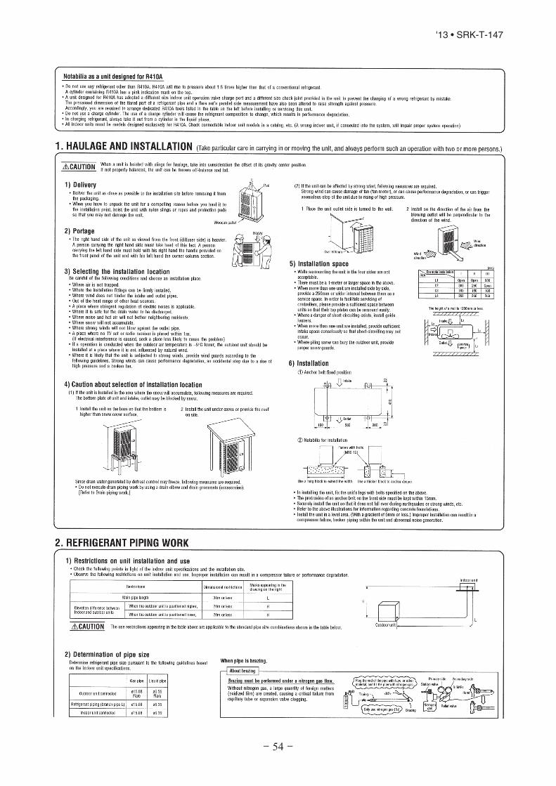
- 54 -
'13 • SRK-T-147

- 55 -
'13 • SRK-T-147

- 56 -
'13 • SRK-T-147

- 73 -
'13 • SRK-T-147
(19) DRED
This air conditioner complies with the DRED (Demand Response Enabling Devices) standard AS/NZS4755.3.1 and
supports below demand resp onsemodes 1, 2, and 3 (DRM1, 2, and 3). Since the air conditioner limits the electric power
or energy by receiving the DRED input signal, the feeling of cooling operation or heating operation may deteriorate during
that time. The outdoor unit of this air conditioner is equipped with a terminal block for DREDinput and supports ELV
Low Vol tage) complying with AS/NZS60335.1.
Under DRED mode, RUN light and TIMER light blink alternately as shown. When the Defrost function becomes effective
during DRED operation, the TIMER light blinks quickly.
(Extra-
RUN light
ON
OFF
2 sec.
2 sec.
2 sec.
2 sec.
ON
OFF
TIMER light
Display in DRED mode Display in DRED mode during Defrost operation
RUN light
ON
OFF
2 sec.
2 sec.
0.5 sec.2 sec.
0.5 sec.
TIMER light
ON
OFF
Table AIR CONDITIONER DEMAND RESPONSE MODES
Demand
response
mode
(DRM)
Description of operation in this mode Remarks
DRM1 Compressor off
DRM2 Compressor speed control
The air conditioner continues to cool or heat during
the demand response event, but the electrical energy
consumed by the air conditioner in a half hour period
is not more than 50% of the total electrical energy that
would be consumed if operating at the rated capacity
in a half hour period.
DRM3 Compressor speed control
The air conditioner continues to cool or heat during
the demand response event, but the electrical energy
consumed by the air conditioner in a half hour period
is not more than 75% of the total electrical energy that
would be consumed if operating at the rated capacity
in a half hour period.