Embed Size (px)
Citation preview

City of Plymouth Building Inspection Division
Residential Decks
Information Sheet
Building permit requirements
A. Signed, completed Building Permit application form. Be sure to include your daytime phone number.
B. Submit two copies of a drawn to scale site plan, based on a Certificate of Survey, indicating the lot dimensions, the location and dimensions of existing structure (s) and the location and dimensions of the proposed structure.
Indicate the setbacks from property lines and wetlands/ buffers (if applicable).
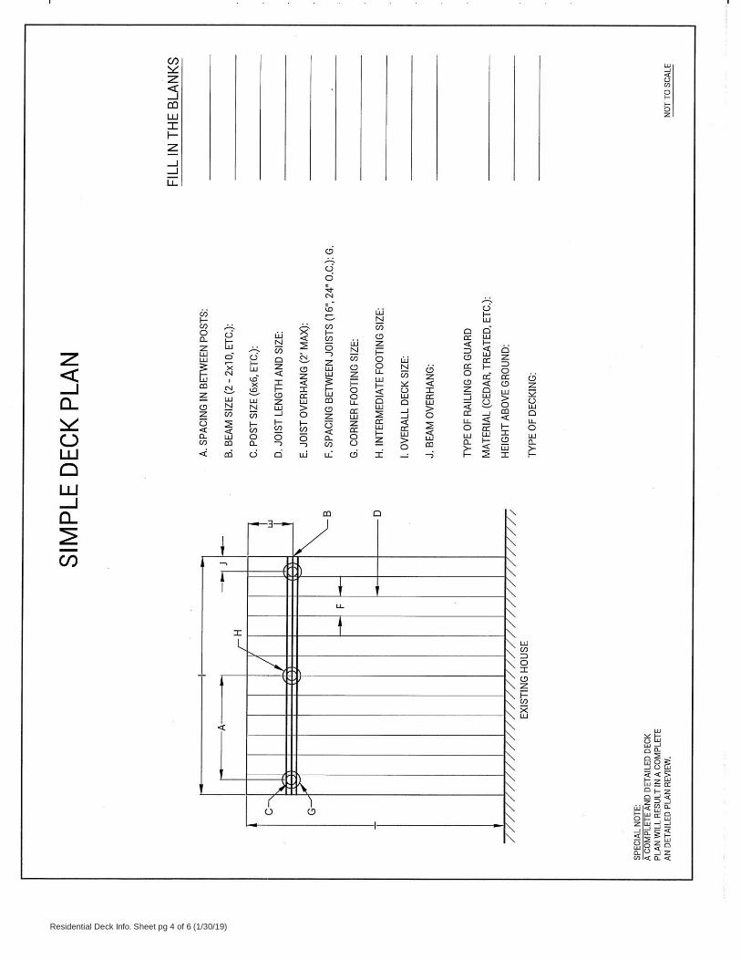
C. Two sets of plans – Submitted plans must have sufficient detail to build the addition from them. A plan view, and elevation is required, all drawn to scale. Indicate all materials and sizes being used. (See pages four and five.)
D. Building permit fee is based on a published fee schedule available at the Building Inspection Division.
Setback requirements Minimum required setback distances from the front, side and rear lot lines may vary according to location. They are set by the Zoning Ordinance. Contact the Community Development Department for this information. When requesting this information, please provide the legal description of the property.
Setback distances are measured from property lines, not from streets, curbs, sidewalks, fences, hedges, trees or poles. Property irons are located underground and they establish property lines.
NOTE: Locating the property corner irons (legal markers) is the responsibility of the property owner; irons must be visible when the footing inspection is requested. Setbacks are measured from the legal property line, wetlands or buffer (if applicable).
General Code requirements Frost footings
Required for any deck attached to a dwelling, porch or garage. The minimum depth to the base of the footing is 42 inches.
Live load
All decks shall be designed to support a live load of 40 pounds per square foot.
Guards/guardrails
Required on all decks or stairs more than 30 inches above grade or a lower deck. See page four for illustration. Exception: On a open stairway, the triangular opening formed by the riser, tread and bottom element of a guardrail must be sized so that a six inch sphere cannot pass through.
Cantilevers: Overhanging joists and beams
Joists should not overhang beams by more than two feet, nor should beams overhang posts by more than one foot unless a special design is approved.
Framing details
Header beams and joists that frame into ledgers or beams shall be supported by approved framing anchors such as joist hangers.
Flashing
All connections between deck and dwelling shall be weatherproof. Cuts in exterior finish shall be flashed.
Nails and screws
Use only stainless steel, high strength aluminum or hot- dipped galvanized.
Wood required
All exposed wood is required to be approved wood with natural resistance to decay (redwood, cedar, etc.) or approved treated wood. This includes posts, beams, joists, decking and railings.
Any composite or plastic decking materials must be approved by the Building Inspection Division prior to installation.
Stairs
Minimum width is 36 inches. Maximum rise is 7-3/4 inches. Minimum run is 10 inches. Largest tread width or riser height shall not exceed the smallest by more than 3/8 inch. Maximum 4 inch opening at risers greater than 30 inches above grade. See Single-Family Stairways/ Guards.
Handrails
The top shall be placed not less than 34 inches or more than 38 inches above the nosing of the treads. Stairways having four or more risers shall have at least one handrail with handrail ends returned or terminated in posts. Circular hand grips shall be between 1-1/4 inches to 2 inches in cross-sectional dimension or the shape shall provide an equivalent gripping surface. See Single-Family Stairways/Guards.
Special design note
Some designs may not be appropriate if a screen porch or 3-season porch on the deck platform is a future consideration. Porch and deck setbacks are not the same.
Lateral Load Connection
A lateral load connection is required from deck to the supporting structure at a minimum of 2 locations. Each connection device shall be rated not less than 1,500 lbs.
Community Development
Department
Building Inspection Division PH 763-509-5430 www.plymouthmn.gov
3400 Plymouth Blvd. FAX 763-509-5407 Residential Deck Info. Sheet pg 1 of 6 (1/30/19)
Plymouth, MN 55447 TTY 763-509-5065
Residential Deck Info. Sheet pg 2 of 6 (1/30/19) )
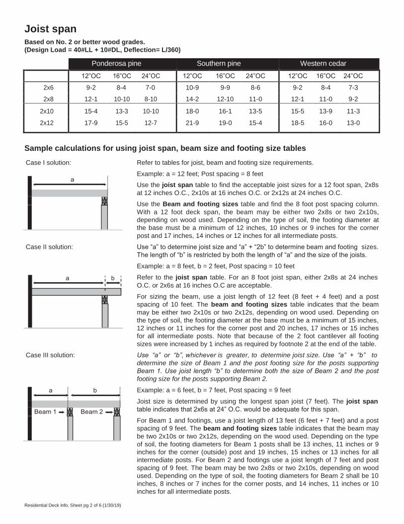
Joist span Based on No. 2 or better wood grades.
(Design Load = 40#LL + 10#DL, Deflection= L/360)
Ponderosa pine Southern pine Western cedar
12”OC 16”OC 24”OC 12”OC 16”OC 24”OC 12”OC 16”OC 24”OC
2x6 9-2 8-4 7-0 10-9 9-9 8-6 9-2 8-4 7-3
2x8 12-1 10-10 8-10 14-2 12-10 11-0 12-1 11-0 9-2
2x10 15-4 13-3 10-10 18-0 16-1 13-5 15-5 13-9 11-3
2x12 17-9 15-5 12-7 21-9 19-0 15-4 18-5 16-0 13-0
Sample calculations for using joist span, beam size and footing size tables
Case I solution: Refer to tables for joist, beam and footing size requirements.
Example: a = 12 feet; Post spacing = 8 feet
Use the joist span table to find the acceptable joist sizes for a 12 foot span, 2x8s
at 12 inches O.C., 2x10s at 16 inches O.C. or 2x12s at 24 inches O.C.
Use the Beam and footing sizes table and find the 8 foot post spacing column.
With a 12 foot deck span, the beam may be either two 2x8s or two 2x10s,
depending on wood used. Depending on the type of soil, the footing diameter at
the base must be a minimum of 12 inches, 10 inches or 9 inches for the corner
post and 17 inches, 14 inches or 12 inches for all intermediate posts.
Case II solution: Use “a” to determine joist size and “a” + “2b” to determine beam and footing sizes.
The length of “b” is restricted by both the length of “a” and the size of the joists.
Example: a = 8 feet, b = 2 feet, Post spacing = 10 feet
Refer to the joist span table. For an 8 foot joist span, either 2x8s at 24 inches
O.C. or 2x6s at 16 inches O.C are acceptable.
For sizing the beam, use a joist length of 12 feet (8 feet + 4 feet) and a post
spacing of 10 feet. The beam and footing sizes table indicates that the beam
may be either two 2x10s or two 2x12s, depending on wood used. Depending on
the type of soil, the footing diameter at the base must be a minimum of 15 inches,
12 inches or 11 inches for the corner post and 20 inches, 17 inches or 15 inches
for all intermediate posts. Note that because of the 2 foot cantilever all footing
sizes were increased by 1 inches as required by footnote 2 at the end of the table.
Case III solution: Use “a” or “b”, whichever is greater, to determine joist size. Use “a” + “b” to
determine the size of Beam 1 and the post footing size for the posts supporting
Beam 1. Use joist length “b” to determine both the size of Beam 2 and the post
footing size for the posts supporting Beam 2.
Example: a = 6 feet, b = 7 feet, Post spacing = 9 feet
Joist size is determined by using the longest span joist (7 feet). The joist span
table indicates that 2x6s at 24” O.C. would be adequate for this span.
For Beam 1 and footings, use a joist length of 13 feet (6 feet + 7 feet) and a post
spacing of 9 feet. The beam and footing sizes table indicates that the beam may
be two 2x10s or two 2x12s, depending on the wood used. Depending on the type
of soil, the footing diameters for Beam 1 posts shall be 13 inches, 11 inches or 9
inches for the corner (outside) post and 19 inches, 15 inches or 13 inches for all
intermediate posts. For Beam 2 and footings use a joist length of 7 feet and post
spacing of 9 feet. The beam may be two 2x8s or two 2x10s, depending on wood
used. Depending on the type of soil, the footing diameters for Beam 2 shall be 10
inches, 8 inches or 7 inches for the corner posts, and 14 inches, 11 inches or 10
inches for all intermediate posts.
a b
a
a b
Beam 1 Beam 2

Beam and footing sizes Based on No. 2 or better Ponderosa Pine and Southern Pine
Post spacing
6’
Southern Pine Beam 1-2x6 1-2x6 1-2x6 2-2x6 2-2x6 2-2x8 2-2x8 2-2x10 2-2x10 2-2x10 2-2x12
Ponderosa Pine Beam 1-2x6 1-2x6 1-2x8 2-2x8 2-2x8 2-2x10 2-2x10 2-2x10 2-2x12 3-2x10 3-2x10 7’
Southern Pine Beam 1-2x6 1-2x6 2-2x6 2-2x6 2-2x8 2-2x8 2-2x8 2-2x10 2-2x10 2-2x12 2-2x12
Ponderosa Pine Beam 1-2x6 2-2x6 2-2x8 2-2x8 2-2x8 2-2x10 2-2x10 2-2x10 3-2x10 3-2x10 3-2x12 8’
Southern Pine Beam 1-2x6 1-2x6 2-2x6 2-2x6 2-2x8 2-2x8 2-2x10 2-2x10 2-2x12 2-2x12 3-2x10
Ponderosa Pine Beam 1-2x6 2-2x6 2-2x8 2-2x8 2-2x10 2-2x10 2-2x10 3-2x10 3-2x10 3-2x12 3-2x12 9’
10’
Southern Pine Beam 1-2x6 1-2x6 2-2x6 2-2x6 2-2x8 2-2x8 2-2x10 2-2x12 2-2x12 3-2x10 3-2x10
Ponderosa Pine Beam 1-2x6 1-2x6 2-2x8 2-2x8 2-2x10 2-2x10 2-2x12 3-2x10 3-2x12 3-2x12 Eng Bm
11’
Southern Pine Beam 1-2x6 2-2x6 2-2x6 2-2x8 2-2x8 2-2x10 2-2x10 2-2x12 2-2x12 3-2x10 3-2x12
Ponderosa Pine Beam 2-2x6 2-2x6 2-2x8 2-2x8 2-2x10 2-2x12 2-2x12 3-2x10 3-2x12 3-2x12 Eng Bm
12’
Southern Pine Beam 1-2x6 2-2x6 2-2x6 2-2x8 2-2x8 2-2x10 2-2x10 2-2x12 3-2x10 3-2x10 3-2x12
Ponderosa Pine Beam 2-2x6 2-2x6 2-2x8 2-2x10 2-2x10 2-2x12 2-2x12 3-2x12 3-2x12 Eng Bm Eng Bm
Corner Footing 9 7 6 10 8 7 10 9 7 11 9 8 12 10 9 13 10 9 14 11 10 14 12 10 15 12 10 15 13 11 16 13 11
Intermediate Footing 12 10 9 14 11 10 15 12 10 16 13 11 17 14 12 18 15 13 19 16 14 20 16 14 21 17 15 22 18 15 23 18 16
13’
Southern Pine Beam 1-2x6 2-2x6 2-2x6 2-2x8 2-2x8 2-2x10 2-2x10 2-2x12 3-2x10 3-2x12 3-2x12
Ponderosa Pine Beam 2-2x6 2-2x6 2-2x8 2-2x10 2-2x12 2-2x12 2-2x12 3-2x12 3-2x12 Eng Bm Eng Bm
Corner Footing 9 7 6 10 8 7 11 9 8 12 10 8 13 10 9 13 11 9 14 12 10 15 12 10 15 13 11 16 13 11 17 14 12
Intermediate Footing 13 10 9 14 12 10 15 13 11 17 14 12 18 15 13 19 15 13 20 16 14 21 17 15 22 18 15 23 19 16 24 19 17
14’
Southern Pine Beam 1-2x6 2-2x6 2-2x6 2-2x8 2-2x10 2-2x10 2-2x12 3-2x10 3-2x12 3-2x12 3-2x12
Ponderosa Pine Beam 2-2x6 2-2x8 2-2x8 2-2x10 2-2x12 3-2x10 3-2x12 3-2x12 Eng Bm Eng Bm Eng Bm
Corner Footing 9 8 7 10 8 7 11 9 8 12 10 9 13 11 9 14 11 10 15 12 10 15 13 11 16 13 11 17 14 12 17 14 12
Intermediate Footing 13 11 9 15 12 10 16 13 11 17 14 12 18 15 13 20 16 14 21 17 15 22 18 15 23 18 16 24 19 17 24 20 17
15’
Southern Pine Beam 2-2x6 2-2x6 2-2x8 2-2x8 2-2x10 2-2x12 2-2x12 3-2x10 3-2x12 3-2x12 Eng Bm
Ponderosa Pine Beam 2-2x6 2-2x8 2-2x8 2-2x10 3-2x10 3-2x10 3-2x12 3-2x12 Eng Bm Eng Bm Eng Bm
Corner Footing 10 8 7 11 9 8 12 10 8 13 10 9 14 11 10 14 12 10 15 12 11 16 13 11 17 14 12 17 14 12 18 15 13
Intermediate Footing 14 11 10 15 12 11 17 14 12 18 15 13 19 16 14 20 17 14 21 17 15 22 18 16 23 19 17 24 20 17 25 21 18
16’
Southern Pine Beam 2-2x6 2-2x6 2-2x8 2-2x8 2-2x10 2-2x12 2-2x12 3-2x10 3-2x12 3-2x12 Eng Bm
Ponderosa Pine Beam 2-2x6 2-2x8 2-2x10 2-2x10 3-2x10 3-2x10 3-2x12 3-2x12 Eng Bm Eng Bm Eng Bm
Corner Footing 10 8 7 11 9 8 12 10 9 13 11 9 14 11 10 15 12 10 16 13 11 16 13 12 17 14 12 18 15 13 18 15 13
Intermediate Footing 14 11 10 16 13 11 17 14 12 18 15 13 20 16 14 21 17 15 22 18 16 23 19 16 24 20 17 25 21 18 26 21 18
Notes:
1. Joist length is total length of joist, including any cantilevers.
2. All footing sizes above are
base diameters (in inches) and are listed for THREE SOIL TYPES:
Residential Deck Info. Sheet pg 3 of 6 (1/30/19)
CLAY
SAND
GRAVEL
Corner Footing 10 8 7
Intermediate Footing 14 11 10
Jo
ist
Len
gth
4’ 5’ 6’ 7’ 8’ 9’ 10’ 11’ 12’ 13’ 14’
Southern Pine Beam 1-2x6 1-2x6 1-2x6 2-2x6 2-2x6 2-2x6 2-2x8 2-2x8 2-2x10 2-2x10 2-2x10
Ponderosa Pine Beam 1-2x6 1-2x6 1-2x8 2-2x8 2-2x8 2-2x8 2-2x10 2-2x10 2-2x12 2-2x12 3-2x10
Corner Footing 6 5 4 7 6 5 7 6 5 8 7 6 9 7 6 9 7 6 10 8 7 10 8 7 10 9 7 11 9 8 11 9 8
Intermediate Footing 9 8 7 10 8 7 10 9 7 11 9 8 12 10 9 13 10 9 14 11 10 14 12 10 15 12 10 15 13 11 16 13 11
Corner Footing 7 5 5 7 6 5 8 7 6 9 7 6 9 8 7 10 8 7 10 8 7 11 9 8 11 9 8 12 10 9 12 10 9
Intermediate Footing 9 8 7 10 8 7 11 9 8 12 10 9 13 11 9 14 11 10 15 12 10 15 13 11 16 13 11 17 14 12 17 14 12
Corner Footing 7 6 5 8 6 6 9 7 6 9 8 7 10 8 7 10 8 7 11 9 8 11 9 8 12 10 9 13 10 9 13 11 9
Intermediate Footing 10 8 7 11 9 8 12 10 9 13 11 9 14 11 10 15 12 10 16 13 11 16 13 12 17 14 12 18 15 13 18 15 13
Corner Footing 7 6 5 8 7 6 9 7 6 10 8 7 10 9 7 11 9 8 12 10 8 12 10 9 13 10 9 13 11 9 14 11 10
Intermediate Footing 10 9 7 12 10 8 13 10 9 14 11 10 15 12 10 16 13 11 17 14 12 17 14 12 18 15 13 19 15 13 20 16 14
Corner Footing 8 6 6 9 7 6 10 8 7 10 8 7 11 9 8 12 10 8 12 10 9 13 11 9 14 11 10 14 12 10 15 12 10
Intermediate Footing 11 9 8 12 10 9 14 11 10 15 12 10 16 13 11 17 14 12 17 14 12 18 15 13 19 16 14 20 16 14 21 17 15
Corner Footing 8 7 6 9 7 6 10 8 7 11 9 8 12 9 8 12 10 9 13 11 9 14 11 10 14 12 10 15 12 10 15 13 11
Intermediate Footing 12 9 8 13 11 9 14 12 10 15 12 10 16 13 11 17 14 12 17 14 12 18 15 13 19 16 14 20 16 14 21 17 15

Residential Deck Info. Sheet pg 4 of 6 (1/30/19)
•
ELEVATION
Inspections Needed
36" Min.
BALUSTER
Less than 4"
NOTE: SKIRTBOARD not required.
RAIL
Flash any cuts in exterior finish
• Footing: When foot-
ings are dug, but
prior to the place-
ment of any concrete.
• Framing:
When height of
deck is less than 30 inches from grade,
and prior to the BEAM (BEST) See Beam and Footing Table NOTES:
MANUFACTURED BEAM SUPPORT
JOIST See Joist Span Table
DECKING 16" or less Span: 1" and 5/4" Over 16" Span: 2"
installation of any
flooring materials.
Any splices in beam must be over a support. All beams of 2 or more members shall be nailed together with 2 rows of 16d Nails at 16" O.C.
POST
ALTERNATE BEAM (BETTER)
Joists rest on BOTH members of beam.
Two 1/2" carriage bolts with washers
LEDGER Same size as joists. Install lag screws that penetrate 11/2" minimum into rim joist or wall studs.
• Final: When required
work is completed.
POST 31/2" Minimum
51/2" Minimum (4X6 or 6X6)
ALTERNATE BEAM (GOOD)
Joists rest on BOTH members of beam.
One 1/2" carriage bolt with washer if 2"X8" or larger beam.
(Minimum two 3/8" lag screws every 16") NOTE: Joist hangers must be correct size for joist size used.
BUILDING
Approved fastener
POST 31/2" Minimum
42"
Two 5/8" bolts with washers through manufactured beam support.
GRADE
CONCRETE PIER
FOOTING 8"
Minimum
Min.
ALTERNATE FOOTING
BACKFILL MATERIAL
WOOD POST
8" 8" POURED CONCRETE FOOTING
Whheen ccaalllliinng foorr aann
innssppeeccttiioon hhaavve
peerrmmiit nuummbbeer ((ss)
avaaiillaabllee.
Quueessttiioonnss?
Neeeed aann IInnssppeeccttiioonn?
Buuiillddiinng IInnssppeeccttiioonn
Diivviissiioon
344000 PPllyymmoouutthh BBllvvdd.
Pllyymmoouutthh,, MMNN 555544447
76633--550099--5544449
FAAXX 776633--550099--55440077
TTTYY 776633--550099--55006655
Residential Deck Info. Sheet pg 4 of 6 (1/30/19)

Residential Deck Info. Sheet pg 6 of 6 (1/30/19)
Deck Plans
IIf yoouu’rree ppllaannnniinngg ttoo buuiilld a ddeeckk, iitt’s iimm-
ppoorrttaanntt tthhaatt yoou ssuubbmmiit ppllaanns tto tthhe BBuuiilldd-
iinngg IInnssppeeccttiioonns DDiivviissiioonn tthhaatt aarre ddeettaaiilleedd
eennoouuggh foor tthhe ppllaan rrevviieweer tto ddeetteermmiinne
tthhaat yoouur pprroojjeecct mmeeeetts ssaafeetty aannd buuiilldd-
iinngg ccooddees.
TThhee BBuuiillddiinngg IInnssppeeccttiioonn DDiivviissiioonn wwiillll nnoot
aacccceeppt ccoommppuutteerr--ggeenneerraatteed ppllaanns tthhaat
aarree oofftteen avaaiillaablle ffrroom llooccaal rreettaaiil hhoomme
iimmpprrooveemmeennt cceenntteerrs. TThhoosse ppllaanns llaack
ssuuffficciieennt ddeettaaiill foor tthhe ppllaan rrevviieweer tto
ccoonndduucctt a proper plan rreevviiew.
IIf yoouu ssuubbmmiitt a ggeenneeriic ppllaan ffrroom a hhoomme
iimmpprrooveemmeennt cceenntteerr wwiitthh yoouur aapppplliiccaattiioonn,
yoouur ppeermmiit wwiillll bbee ddeellaayeedd bbeeccaauusse yoouur
aapppplliiccaattiioonn ccaannnnoott bbee pprroocceesssseed aannd wwiillll
bbe rreettuurnneed ttoo yoouu.
To lleeaarrn mmoorree aabboouut tthhe iinnfoormmaattiioon tthhaat
iis rreeqquuiirreedd foor tthheesse pprroojjeecctts, pplleeaasse ppiick
uup a hhaannddoouut aatt tthhe BBuuiillddiinngg IInnssppeeccttiioonn
SSeerrvviiccee CCoouunntteer iinn CCiittyy HHaallll oorr vviissiit tthhe
CCiitty weebb ssiittee aatt wwwww..ppllyymmoouutthhmmnn..ggov..uus.