Embed Size (px)
Citation preview
IMPORTANTREAD THESE INSTRUCTIONS CAREFULLY BEFORE BEGINNING THE INSTALLATION. PROPER INSTALLATION WILL PROVIDE SAFE AND EFFICIENT SERVICE, AND AVOID NEEDLESS EXPENSE NOT COVERED BY THE WARRANTY. READ THE PRODUCT WARRANTY CONTAINED IN THIS MANUAL AND REMEMBER TO FILL OUT AND RETURN TO THE MANUFACTURER ALL RELEVANT WARRANTY CARDS AND CERTIFICATES. SHOULD YOU HAVE ANY QUESTIONS, PLEASE CONTACT YOUR LOCAL DEALER OR REFER TO THE GETTING SERVICE FOR YOUR WATER HEATER SECTION OF THIS MANUAL.SAVE THIS MANUAL FOR FUTURE REFERENCES.
RESIDENTIAL ELECTRIC WATER HEATER
OWNER’S MANUAL
INSTALLATION AND OPERATING INSTRUCTIONS
ISO 9001ENREGISTRÉ
ISO 9001REGISTRED
If the information in these instructions is not followed exactly, a fire or explosion may result causing property damage, personal injury, or death.
• DO NOT REMOVE the element and thermostat access cover before the power to the water heater is turned “OFF”.
• DO NOT ATTEMPT to repair or replace any of the electrical components installed on the water heater before the power to the water heater is turned “OFF”.
• DO NOT USE the water heater on a voltage other than that specified on the water heater rating plate.
• DO NOT CONNECT the power supply wiring to anywhere other than the main power connection on the water heater.
• DO NOT TURN ON the power to the water heater unless it is completely filled with water.
• DO NOT DRAIN the water heater unless the power to the water heater has been turned “OFF”.
• DO NOT STORE or use gasoline or other flammable vapours and liquids in the vicinity of this or any other appliance.
WHAT TO DO IF YOU SMELL SMOKE• Immediately turn “OFF” the power to the water heater.• If after turning “OFF” the power the smoke
continues, call your local fire department.• When the smoke has stopped, call a qualified service
technician to identify and repair the problem.
For your records, write the model and serial number here:
Model # ________________________________________
Serial # ________________________________________
GE-IM017En-1211
WARNING
AVERTISSEMENT
DANGER
C US
®
54000028© 2011 Gemco Inc. Printed in Canada
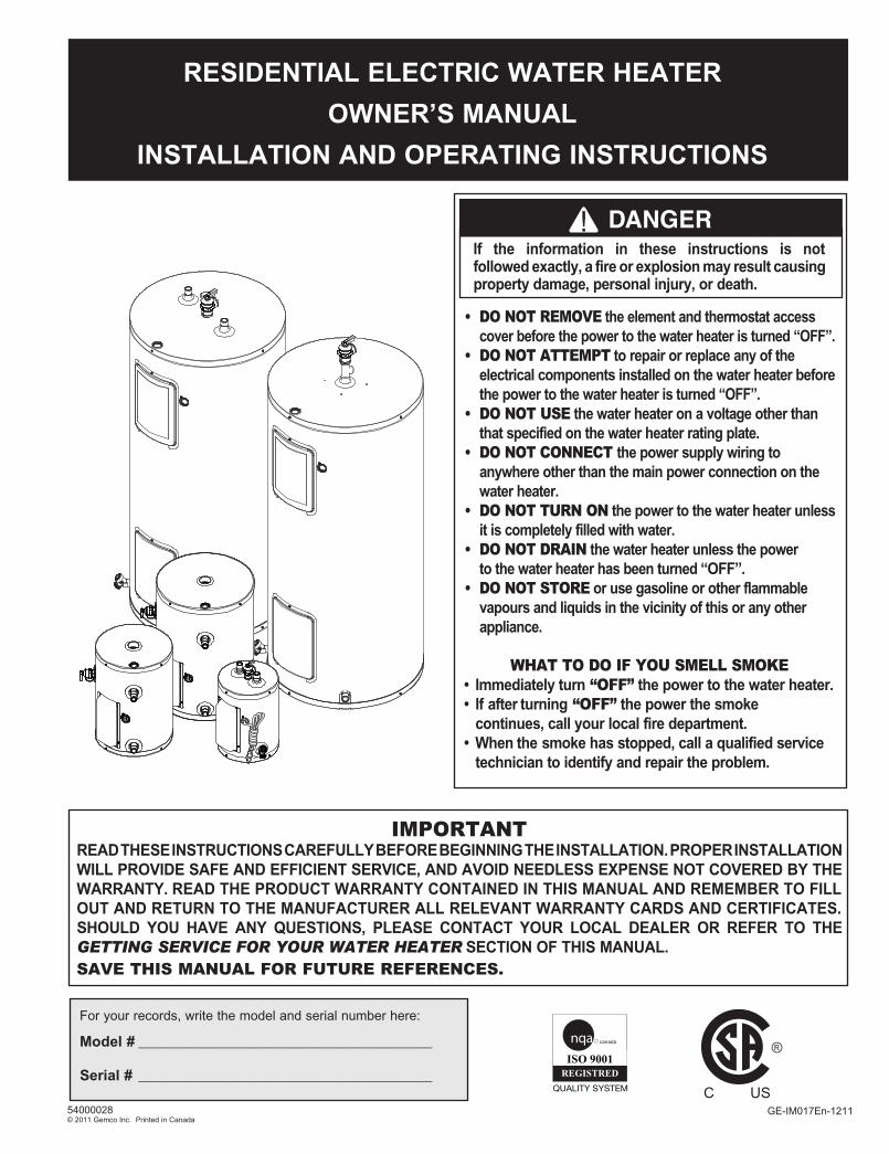
45.0°
48 3/4''
45.0°
2 1/8''
Ø22''
Man Electrique-GI-IM017Bi-1211.indd 2 11-12-21 12:29 PM
WARNING
AVERTISSEMENT
DANGER
WARNING
AVERTISSEMENT
DANGER
2
TABLE OF CONTENTSSafety Information . . . . . . . . . . . . . . . . . . . . . . . . . . . . . . . . 2Installation Instructions . . . . . . . . . . . . . . . . . . . . . . . . . . 3 Location . . . . . . . . . . . . . . . . . . . . . . . . . . . . . . . . . . . . . . 3 Water Piping . . . . . . . . . . . . . . . . . . . . . . . . . . . . . . . . . . 3 Temperature & Pressure-Relief Valve . . . . . . . . . . . 3 Pressure Build-up in a Water System . . . . . . . . . . . . 3 Filling the Water Heater . . . . . . . . . . . . . . . . . . . . . . . . 3 Electrical Connections . . . . . . . . . . . . . . . . . . . . . . . . . . 6 Insulation Blankets . . . . . . . . . . . . . . . . . . . . . . . . . . . . . . 6 Installation Checklist . . . . . . . . . . . . . . . . . . . . . . . . . . . 8Operating Instructions . . . . . . . . . . . . . . . . . . . . . . . . . . . 8 Starting the Water Heater . . . . . . . . . . . . . . . . . . . . . . 8 Start-up Procedure . . . . . . . . . . . . . . . . . . . . . . . . . . . . . . 9 Safety Controls . . . . . . . . . . . . . . . . . . . . . . . . . . . . . . . . . 9
Water Temperature Regulation . . . . . . . . . . . . . . . . . 9General Maintenance . . . . . . . . . . . . . . . . . . . . . . . . . . . . . 9 Condensation . . . . . . . . . . . . . . . . . . . . . . . . . . . . . . . . . 9 Water Heater Tank. . . . . . . . . . . . . . . . . . . . . . . . . . . . . 9 Element and Thermostat Replacement . . . . . . . . . . . 9 Temperature and Pressure-Relief Valve . . . . . . . . 10 Anode . . . . . . . . . . . . . . . . . . . . . . . . . . . . . . . . . . . . . . . 10 Draining the Water Heater . . . . . . . . . . . . . . . . . . . . 11 Vacation . . . . . . . . . . . . . . . . . . . . . . . . . . . . . . . . . . . . . 11 Getting Service for your Water Heater . . . . . . . . . . 11Replacement Parts . . . . . . . . . . . . . . . . . . . . . . . . . . . . . . . 12Troubleshooting Guide . . . . . . . . . . . . . . . . . . . . . . . . . . 14Warranty . . . . . . . . . . . . . . . . . . . . . . . . . . . . . . . . . . . . . . . . 16
SAFETY INFORMATIONYour safety and the safety of others is extremely important during the installation, operation, and servicing of this water heater. Many safety-related messages have been provided in this manual and on your water heater. Always read and obey all safety messages. These messages will point out the potential hazard, tell you how to reduce the risk of injury, and tell you what will happen if the instructions are not followed.
This is the safety alert symbol. This symbol alerts you to potential hazards that can kill or hurt you and others. All safety messages will follow the safety alert symbol and either the word “DANGER” or “WARNING”.
Serious injury or death can occur if you do not follow the instructions immediately.
Serious injury or death can occur if you do not follow the instructions.
WARNING
AVERTISSEMENT
DANGERDO NOT use this water heater if any part has been under water. Immediately call a qualified service technician to inspect the water heater and to replace any part of the control system which has been under water. Failure to follow this instruction can result in property damage, personal injury, or death.
Before proceeding with the installation instructions:
1) Inspect the water heater and its component parts for possible damage. DO NOT install or attempt to repair any damaged component parts. If you detect any damage, contact the dealer where the water heater was purchased or the manufacturer listed on the warranty card.
2) Verify that the voltage being supplied corresponds to that which is marked on the water heater rating plate.
IMPORTANT These instructions have been written as a guide for the proper installation and operation of your water heater, and the manufac-turer of this water heater will not accept any liability where these instructions have not been followed. However, for your safety and to avoid damage caused by improper installation, this water heater must be installed by a Certified Licensed Professional, and meet all local codes or, in the absence of local codes, CSA C22.1 Canadian Electrical Code, in Canada, and/or the National Electrical Code, ANSI/NFPA 70, in the United States.
Man Electrique-GI-IM017Bi-1211.indd 3 11-12-21 12:29 PM
3
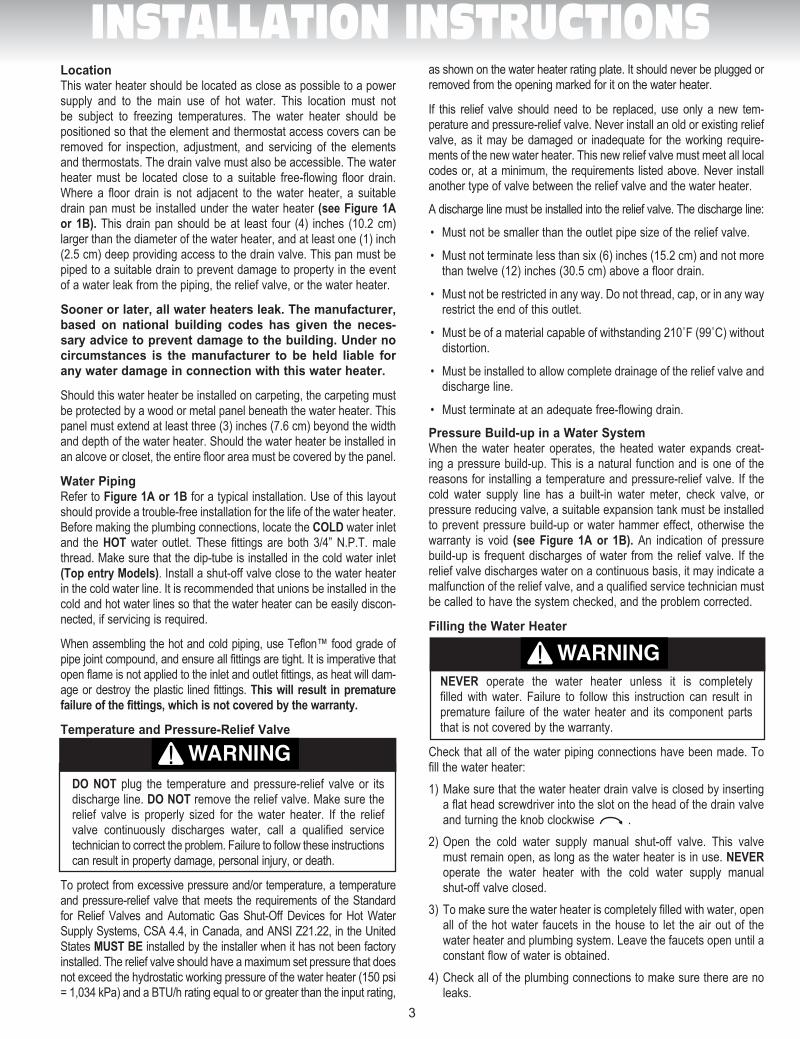
LocationThis water heater should be located as close as possible to a power supply and to the main use of hot water. This location must not be subject to freezing temperatures. The water heater should be positioned so that the element and thermostat access covers can be removed for inspection, adjustment, and servicing of the elements and thermostats. The drain valve must also be accessible. The water heater must be located close to a suitable free-flowing floor drain. Where a floor drain is not adjacent to the water heater, a suitable drain pan must be installed under the water heater (see Figure 1A or 1B). This drain pan should be at least four (4) inches (10.2 cm) larger than the diameter of the water heater, and at least one (1) inch (2.5 cm) deep providing access to the drain valve. This pan must be piped to a suitable drain to prevent damage to property in the event of a water leak from the piping, the relief valve, or the water heater.
Sooner or later, all water heaters leak. The manufacturer, based on national building codes has given the neces-sary advice to prevent damage to the building. Under no circumstances is the manufacturer to be held liable for any water damage in connection with this water heater.
Should this water heater be installed on carpeting, the carpeting must be protected by a wood or metal panel beneath the water heater. This panel must extend at least three (3) inches (7.6 cm) beyond the width and depth of the water heater. Should the water heater be installed in an alcove or closet, the entire floor area must be covered by the panel.
Water PipingRefer to Figure 1A or 1B for a typical installation. Use of this layout should provide a trouble-free installation for the life of the water heater. Before making the plumbing connections, locate the COLD water inlet and the HOT water outlet. These fittings are both 3/4” N.P.T. male thread. Make sure that the dip-tube is installed in the cold water inlet (Top entry Models). Install a shut-off valve close to the water heater in the cold water line. It is recommended that unions be installed in the cold and hot water lines so that the water heater can be easily discon-nected, if servicing is required.
When assembling the hot and cold piping, use Teflon™ food grade of pipe joint compound, and ensure all fittings are tight. It is imperative that open flame is not applied to the inlet and outlet fittings, as heat will dam-age or destroy the plastic lined fittings. This will result in premature failure of the fittings, which is not covered by the warranty.
Temperature and Pressure-Relief Valve
DO NOT plug the temperature and pressure-relief valve or its discharge line. DO NOT remove the relief valve. Make sure the relief valve is properly sized for the water heater. If the relief valve continuously discharges water, call a qualified service technician to correct the problem. Failure to follow these instructions can result in property damage, personal injury, or death.
To protect from excessive pressure and/or temperature, a temperature and pressure-relief valve that meets the requirements of the Standard for Relief Valves and Automatic Gas Shut-Off Devices for Hot Water Supply Systems, CSA 4.4, in Canada, and ANSI Z21.22, in the United States MUST BE installed by the installer when it has not been factory installed. The relief valve should have a maximum set pressure that does not exceed the hydrostatic working pressure of the water heater (150 psi = 1,034 kPa) and a BTU/h rating equal to or greater than the input rating,
as shown on the water heater rating plate. It should never be plugged or removed from the opening marked for it on the water heater.
If this relief valve should need to be replaced, use only a new tem-perature and pressure-relief valve. Never install an old or existing relief valve, as it may be damaged or inadequate for the working require-ments of the new water heater. This new relief valve must meet all local codes or, at a minimum, the requirements listed above. Never install another type of valve between the relief valve and the water heater.
A discharge line must be installed into the relief valve. The discharge line:
• Mustnotbesmallerthantheoutletpipesizeofthereliefvalve.
• Mustnotterminatelessthansix(6)inches(15.2cm)andnotmorethan twelve (12) inches (30.5 cm) above a floor drain.
• Mustnotberestrictedinanyway.Donotthread,cap,orinanywayrestrict the end of this outlet.
• Mustbeofamaterialcapableofwithstanding210˚F(99˚C)withoutdistortion.
• Mustbeinstalledtoallowcompletedrainageofthereliefvalveanddischarge line.
• Mustterminateatanadequatefree-flowingdrain.
Pressure Build-up in a Water SystemWhen the water heater operates, the heated water expands creat-ing a pressure build-up. This is a natural function and is one of the reasons for installing a temperature and pressure-relief valve. If the cold water supply line has a built-in water meter, check valve, or pressure reducing valve, a suitable expansion tank must be installed to prevent pressure build-up or water hammer effect, otherwise the warranty is void (see Figure 1A or 1B). An indication of pressure build-up is frequent discharges of water from the relief valve. If the relief valve discharges water on a continuous basis, it may indicate a malfunction of the relief valve, and a qualified service technician must be called to have the system checked, and the problem corrected.
Filling the Water Heater
NEVER operate the water heater unless it is completely filled with water. Failure to follow this instruction can result in premature failure of the water heater and its component parts that is not covered by the warranty.
Check that all of the water piping connections have been made. To fill the water heater:
1) Make sure that the water heater drain valve is closed by inserting a flat head screwdriver into the slot on the head of the drain valve and turning the knob clockwise .
2) Open the cold water supply manual shut-off valve. This valve must remain open, as long as the water heater is in use. NEVER operate the water heater with the cold water supply manual shut-off valve closed.
3) To make sure the water heater is completely filled with water, open all of the hot water faucets in the house to let the air out of the water heater and plumbing system. Leave the faucets open until a constant flow of water is obtained.
4) Check all of the plumbing connections to make sure there are no leaks.
INSTALLATION INSTRUCTIONS
WARNING
AVERTISSEMENT
DANGER
WARNING
AVERTISSEMENT
DANGER
Man Electrique-GI-IM017Bi-1211.indd 4 11-12-21 12:29 PM
4
INSTALLATION INSTRUCTIONS
ID No. Description 1 Check valve, water meter or pressure reducing valve 2 Cold water manual shut-off valve 3 Union 4 Cold water intlet 5 Temperature & pressure-relief valve 6 Expansion tank 7 Overflow tube 8 Dip-tube 9 Drain pan 10 Free-flowing floor drain 11 Lower element 12 Drain valve 13 Element and thermostat access covers 14 Lower thermostat 15 Magnesium anode rod 16 Upper element 17 Combination upper thermostat and high limit reset control 18 Hot water outlet 19 Union 20 Hot water manual shut-off valve
1234519
20
1
13
14
3
2a2b
13
12a
2b
34
5678
9
10
11
12
14
15
6
7
9
10
1112
13 14
17
18
15
16
8
1234519
20
6
7
9
10
1112
13 14
17
18
15
16
8
ID No. Description 1 Check valve, water meter or pressure reducing valve 2 Cold water manual shut-off valve 3 Union 4 Vacuum breaker 5 Temperature & pressure-relief valve 6 Expansion tank 7 Overflow tube 8 Drain pan 9 Free-flowing floor drain 10 Cold water intlet 11 Lower element 12 Drain valve 13 Element and thermostat access covers 14 Lower thermostat 15 Magnesium anode rod 16 Upper element 17 Combination upper thermostat and high limit reset control 18 Hot water outlet 19 Union 20 Hot water manual shut-off valve
ID No. Description 1 Upper thermostat with reset 2a High limit reset control 2b Upper thermostat 3 Element gasket 4 Upper element 5 Drain valve 6 Lower Thermostat 7 Thermostat bracket 8 Machine bolt & hex head nut 9 Element and thermostat access cover 10 Lower element 11 Dip tube 12 Magnesium anode rod 13 Extention fitting 14 Outlet nipple 15 Temperature & pressure-relief Valve
ID No. Description 1 Upper thermostat with reset 2a High limit reset control 2b Upper thermostat 3 Element gasket 4 Upper element 5 Drain valve 6 Lower Thermostat 7 Thermostat bracket 8 Machine bolt & hex head nut 9 Element and thermostat access cover 10 Lower element 11 Inlet nipple 12 Magnesium anode rod 13 Outlet nipple 14 Brass “T” 15 Temperature & pressure-relief Valve 4
5
9
6
10
11
127
8
1
14
3
2a2b
45
9
6
10
11
127
8
Num. Description 1 Thermostat du haut avec interrupteur secondaire 2a Interrupteur secondaire 2b Thermostat du haut 3 Joint d’étanchéité pour élément 4 Élément du haut 5 Robinet de vidange 6 Thermostat du bas 7 Support pour thermostat 8 Vis et écrou 9 Porte d’accès aux éléments et thermostats 10 Élément du bas 11 Raccord d’entrée 12 Anode de magnésium 13 Raccord de sortie 14 «T» en laiton 15 Soupape température et pression
Num. Description 1 Thermostat du haut avec interrupteur secondaire 2a Interrupteur secondaire 2b Thermostat du haut 3 Joint d’étanchéité pour élément 4 Élément du haut 5 Robinet de vidange 6 Thermostat du bas 7 Support pour thermostat 8 Vis et écrou 9 Porte d’accès aux éléments et thermostats 10 Élément du bas 11 Tuyau plongeur 12 Anode de magnésium 13 Raccord de rallonge 14 Raccord de sortie 15 Soupape température et pression
Num. Description 1 Compteur d’eau ou clapet ou soupape de réduction de pression 2 Robinet d’arrêt d’eau froide manuel 3 Raccord 4 Brise vide 5 Soupape de sécurité de température et pression 6 Réservoir d’expansion 7 Tuyau d’évacuation 8 Bassin de rétention 9 Drain de plancher 10 Entrée d’eau froide 11 Élément du bas 12 Robinet de vidange 13 Portes d’accès aux éléments et thermostats 14 Thermostat du bas 15 Anode de magnésium 16 Élément du haut 17 Thermosat du haut avec interrupteur secondaire 18 Sortie d’eau chaude 19 Raccord 20 Robinet d’arrêt d’eau chaude manuel
Num. Description 1 Compteur d’eau ou clapet ou soupape de réduction de pression 2 Robinet d’arrêt d’eau froide manuel 3 Raccord 4 Entrée d’eau froide 5 Soupape de sécurité de température et pression 6 Réservoir d’expansion 7 Tuyau d’évacuation 8 Tuyau plongeur 9 Bassin de rétention 10 Drain de plancher 11 Élément du bas 12 Robinet de vidange 13 Portes d’accès aux éléments et thermostats 14 Thermostat du bas 15 Anode de magnésium 16 Élément du haut 17 Thermosat du haut avec interrupteur secondaire 18 Sortie d’eau chaude 19 Raccord 20 Robinet d’arrêt d’eau chaude manuel
13
12a
2b
34
5678
9
10
11
12
1
6
7
8
9
101112
23
45
1920
13
141516
17
1
6
7
8
9
101112
23
45
1920
18
18
13
141516
17
16
15
1413
11
121
2
45
6
3
7
17
18
9
10
8
3
2 1
16 15 14
13
11
108
76
9
4
5 12
1718
3
2 1
16 15 14
13
11
108
76
9
4
5 12
1718
Num. Description 1) Sortie d’eau chaude 2) Raccord 3) Robinet d’arrêt d’eau chaude manuel 4) Soupape de sûreté de température et pression 5) Raccord de sortie/anode de magnésium combinés 6) Thermostat avec interrupteur secondaire 7) Porte d’accès à l’élément et au thermostat 8) Élément vissé 9) Robinet de vidange 10) Drain de plancher 11) Bassin de rétention 12) Réservoir d’expansion 13) Tuyau plongeur 14) Compteur d’eau ou clapet ou soupape de réduction de pression 15) Robinet d’arrêt d’eau froide manuel 16) Tuyau d’évacuation 17) Raccord 18) Entrée d’eau froide
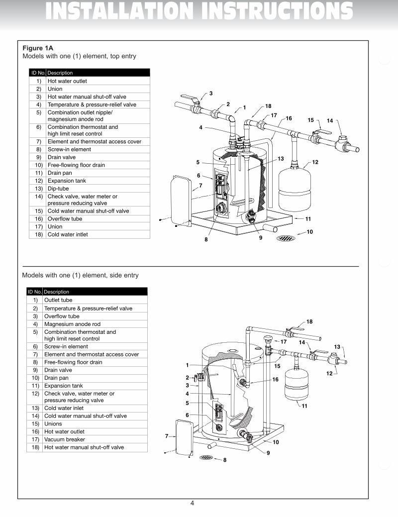
ID No. Description 1) Hot water outlet 2) Union 3) Hot water manual shut-off valve 4) Temperature & pressure-relief valve 5) Combination outlet nipple/ magnesium anode rod 6) Combination thermostat and high limit reset control 7) Element and thermostat access cover 8) Screw-in element 9) Drain valve 10) Free-flowing floor drain 11) Drain pan 12) Expansion tank 13) Dip-tube 14) Check valve, water meter or pressure reducing valve 15) Cold water manual shut-off valve 16) Overflow tube 17) Union 18) Cold water intlet
Num. Description 1) Tuyau de sortie 2) Soupape de sûreté de température et pression 3) Tuyau d’évacuation 4) Anode 5) Thermostat avec interrupteur secondaire 6) Élément vissé 7) Porte d’accès à l’élément et au thermostat 8) Drain de plancher 9) Robinet de vidange 10) Bassin de rétention 11) Réservoir d’expansion 12) Compteur d’eau ou clapet ou soupape de réduction de pression 13) Entrée d’eau froide 14) Robinet d’arrêt d’eau froide manuel 15) Raccords 16) Sortie d’eau chaude 17) Brise vide 18) Robinet d’arrêt d’eau chaude manuel
ID No. Description 1) Outlet tube
2) Temperature & pressure-relief valve 3) Over�ow tube 4) Magnesium anode rod 5) Combination thermostat and high limit reset control 6) Screw-in element 7) Element and thermostat access cover 8) Free-�owing �oor drain 9) Drain valve 10) Drain pan 11) Expansion tank 12) Check valve, water meter or pressure reducing valve 13) Cold water inlet 14) Cold water manual shut-off valve 15) Unions 16) Hot water outlet 17) Vacuum breaker 18) Hot water manual shut-off valve
16
15
1413
11
121
2
45
6
3
7
17
18
9
10
8
9 4 7 1
13 16 17
9 4 7 1
ID No. Description 1 Combination thermostat and high limit reset control 2 High limit reset control 3 Thermostat 4 Element and thermostat access cover 5 Screw-in element gasket 6 Screw-in element 7 Thermostat bracket for screw-in element 8 Drain valve 9 Dip-tube 10 Temperature & pressure-relief valve 11 Combination outlet nipple/magnesium anode rod
123
4
56 7 8
9
1011
ID No. Description 1 Combination thermostat and high limit reset control 2 High limit reset control 3 Thermostat 4 Element and thermostat access cover 5 Screw-in element gasket 6 Screw-in element 7 Thermostat bracket for screw-in element 8 Inlet nipple 9 Outlet nipple with tube 10 Magnesium anode rod 11 Temperature & pressure-relief valve 1 2
3
4
56 7
8
9
10
11
ID No. Description 1 Thermostat avec interrupteur secondaire 2 Interrupteur secondaire 3 Thermostat 4 Porte d’accès à l’élément et au thermostat 5 Joint d’étanchéité pour élément vissé 6 Élément vissé 7 Support pour thermostat avec élément vissé 8 Robinet de vidange 9 Tuyau plongeur 10 Soupape de sûreté de température et pression 11 Raccord de sortie/anode de magnésium combiné
Num. Description 1 Thermostat avec interrupteur secondaire 2 Interrupteur secondaire 3 Thermostat 4 Porte d’accès à l’élément et au thermostat 5 Joint d’étanchéité pour élément vissé 6 Élément vissé 7 Support pour thermostat avec élément vissé 8 Raccord d’entrée 9 Raccord de sortie avec tuyau 10 Anode de magnésium 11 Soupape de sûreté de température et pression 1 2
3
4
56 7
8
9
10
11
123
4
56 7 8
9
1011
13 16 17
14
15
15
13
15
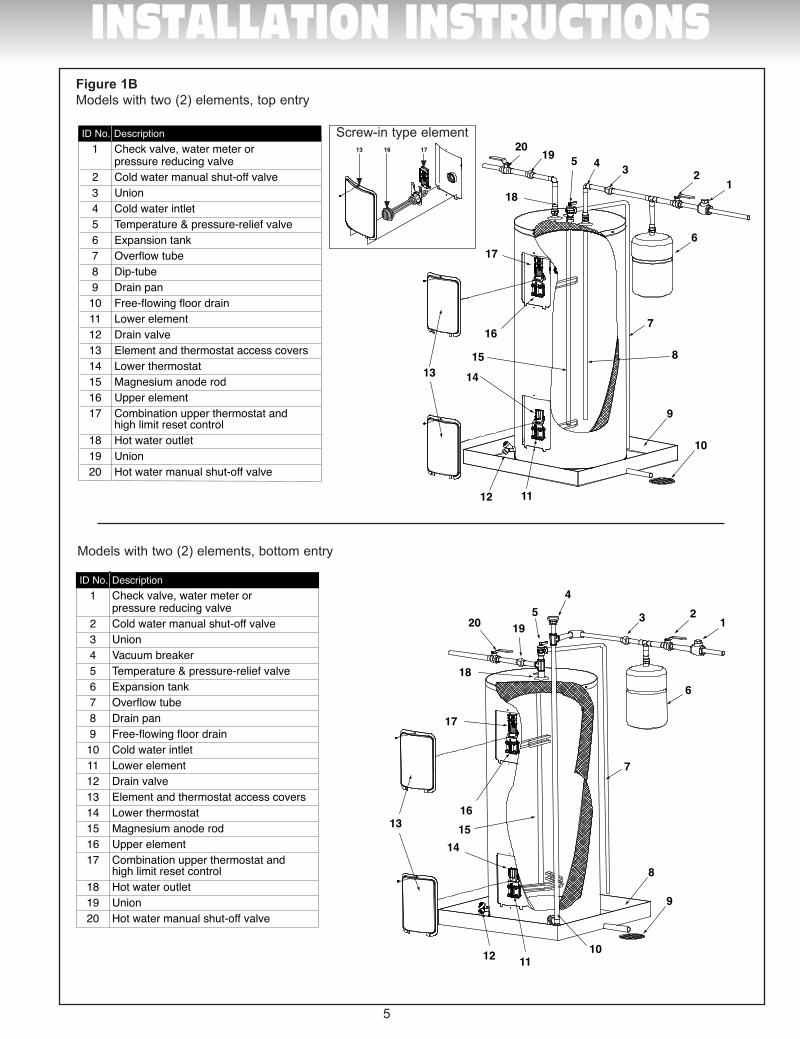
ID No. Description 1 Check valve, water meter or pressure reducing valve 2 Cold water manual shut-off valve 3 Union 4 Cold water intlet 5 Temperature & pressure-relief valve 6 Expansion tank 7 Overflow tube 8 Dip-tube 9 Drain pan 10 Free-flowing floor drain 11 Lower element 12 Drain valve 13 Element and thermostat access covers 14 Lower thermostat 15 Magnesium anode rod 16 Upper element 17 Combination upper thermostat and high limit reset control 18 Hot water outlet 19 Union 20 Hot water manual shut-off valve
1234519
20
1
13
14
3
2a2b
13
12a
2b
34
5678
9
10
11
12
14
15
6
7
9
10
1112
13 14
17
18
15
16
8
1234519
20
6
7
9
10
1112
13 14
17
18
15
16
8
ID No. Description 1 Check valve, water meter or pressure reducing valve 2 Cold water manual shut-off valve 3 Union 4 Vacuum breaker 5 Temperature & pressure-relief valve 6 Expansion tank 7 Overflow tube 8 Drain pan 9 Free-flowing floor drain 10 Cold water intlet 11 Lower element 12 Drain valve 13 Element and thermostat access covers 14 Lower thermostat 15 Magnesium anode rod 16 Upper element 17 Combination upper thermostat and high limit reset control 18 Hot water outlet 19 Union 20 Hot water manual shut-off valve
ID No. Description 1 Upper thermostat with reset 2a High limit reset control 2b Upper thermostat 3 Element gasket 4 Upper element 5 Drain valve 6 Lower Thermostat 7 Thermostat bracket 8 Machine bolt & hex head nut 9 Element and thermostat access cover 10 Lower element 11 Dip tube 12 Magnesium anode rod 13 Extention fitting 14 Outlet nipple 15 Temperature & pressure-relief Valve
ID No. Description 1 Upper thermostat with reset 2a High limit reset control 2b Upper thermostat 3 Element gasket 4 Upper element 5 Drain valve 6 Lower Thermostat 7 Thermostat bracket 8 Machine bolt & hex head nut 9 Element and thermostat access cover 10 Lower element 11 Inlet nipple 12 Magnesium anode rod 13 Outlet nipple 14 Brass “T” 15 Temperature & pressure-relief Valve 4
5
9
6
10
11
127
8
1
14
3
2a2b
45
9
6
10
11
127
8
Num. Description 1 Thermostat du haut avec interrupteur secondaire 2a Interrupteur secondaire 2b Thermostat du haut 3 Joint d’étanchéité pour élément 4 Élément du haut 5 Robinet de vidange 6 Thermostat du bas 7 Support pour thermostat 8 Vis et écrou 9 Porte d’accès aux éléments et thermostats 10 Élément du bas 11 Raccord d’entrée 12 Anode de magnésium 13 Raccord de sortie 14 «T» en laiton 15 Soupape température et pression
Num. Description 1 Thermostat du haut avec interrupteur secondaire 2a Interrupteur secondaire 2b Thermostat du haut 3 Joint d’étanchéité pour élément 4 Élément du haut 5 Robinet de vidange 6 Thermostat du bas 7 Support pour thermostat 8 Vis et écrou 9 Porte d’accès aux éléments et thermostats 10 Élément du bas 11 Tuyau plongeur 12 Anode de magnésium 13 Raccord de rallonge 14 Raccord de sortie 15 Soupape température et pression
Num. Description 1 Compteur d’eau ou clapet ou soupape de réduction de pression 2 Robinet d’arrêt d’eau froide manuel 3 Raccord 4 Brise vide 5 Soupape de sécurité de température et pression 6 Réservoir d’expansion 7 Tuyau d’évacuation 8 Bassin de rétention 9 Drain de plancher 10 Entrée d’eau froide 11 Élément du bas 12 Robinet de vidange 13 Portes d’accès aux éléments et thermostats 14 Thermostat du bas 15 Anode de magnésium 16 Élément du haut 17 Thermosat du haut avec interrupteur secondaire 18 Sortie d’eau chaude 19 Raccord 20 Robinet d’arrêt d’eau chaude manuel
Num. Description 1 Compteur d’eau ou clapet ou soupape de réduction de pression 2 Robinet d’arrêt d’eau froide manuel 3 Raccord 4 Entrée d’eau froide 5 Soupape de sécurité de température et pression 6 Réservoir d’expansion 7 Tuyau d’évacuation 8 Tuyau plongeur 9 Bassin de rétention 10 Drain de plancher 11 Élément du bas 12 Robinet de vidange 13 Portes d’accès aux éléments et thermostats 14 Thermostat du bas 15 Anode de magnésium 16 Élément du haut 17 Thermosat du haut avec interrupteur secondaire 18 Sortie d’eau chaude 19 Raccord 20 Robinet d’arrêt d’eau chaude manuel
13
12a
2b
34
5678
9
10
11
12
1
6
7
8
9
101112
23
45
1920
13
141516
17
1
6
7
8
9
101112
23
45
1920
18
18
13
141516
17
16
15
1413
11
121
2
45
6
3
7
17
18
9
10
8
3
2 1
16 15 14
13
11
108
76
9
4
5 12
1718
3
2 1
16 15 14
13
11
108
76
9
4
5 12
1718
Num. Description 1) Sortie d’eau chaude 2) Raccord 3) Robinet d’arrêt d’eau chaude manuel 4) Soupape de sûreté de température et pression 5) Raccord de sortie/anode de magnésium combinés 6) Thermostat avec interrupteur secondaire 7) Porte d’accès à l’élément et au thermostat 8) Élément vissé 9) Robinet de vidange 10) Drain de plancher 11) Bassin de rétention 12) Réservoir d’expansion 13) Tuyau plongeur 14) Compteur d’eau ou clapet ou soupape de réduction de pression 15) Robinet d’arrêt d’eau froide manuel 16) Tuyau d’évacuation 17) Raccord 18) Entrée d’eau froide
ID No. Description 1) Hot water outlet 2) Union 3) Hot water manual shut-off valve 4) Temperature & pressure-relief valve 5) Combination outlet nipple/ magnesium anode rod 6) Combination thermostat and high limit reset control 7) Element and thermostat access cover 8) Screw-in element 9) Drain valve 10) Free-flowing floor drain 11) Drain pan 12) Expansion tank 13) Dip-tube 14) Check valve, water meter or pressure reducing valve 15) Cold water manual shut-off valve 16) Overflow tube 17) Union 18) Cold water intlet
Num. Description 1) Tuyau de sortie 2) Soupape de sûreté de température et pression 3) Tuyau d’évacuation 4) Anode 5) Thermostat avec interrupteur secondaire 6) Élément vissé 7) Porte d’accès à l’élément et au thermostat 8) Drain de plancher 9) Robinet de vidange 10) Bassin de rétention 11) Réservoir d’expansion 12) Compteur d’eau ou clapet ou soupape de réduction de pression 13) Entrée d’eau froide 14) Robinet d’arrêt d’eau froide manuel 15) Raccords 16) Sortie d’eau chaude 17) Brise vide 18) Robinet d’arrêt d’eau chaude manuel
ID No. Description 1) Outlet tube
2) Temperature & pressure-relief valve 3) Over�ow tube 4) Magnesium anode rod 5) Combination thermostat and high limit reset control 6) Screw-in element 7) Element and thermostat access cover 8) Free-�owing �oor drain 9) Drain valve 10) Drain pan 11) Expansion tank 12) Check valve, water meter or pressure reducing valve 13) Cold water inlet 14) Cold water manual shut-off valve 15) Unions 16) Hot water outlet 17) Vacuum breaker 18) Hot water manual shut-off valve
16
15
1413
11
121
2
45
6
3
7
17
18
9
10
8
9 4 7 1
13 16 17
9 4 7 1
ID No. Description 1 Combination thermostat and high limit reset control 2 High limit reset control 3 Thermostat 4 Element and thermostat access cover 5 Screw-in element gasket 6 Screw-in element 7 Thermostat bracket for screw-in element 8 Drain valve 9 Dip-tube 10 Temperature & pressure-relief valve 11 Combination outlet nipple/magnesium anode rod
123
4
56 7 8
9
1011
ID No. Description 1 Combination thermostat and high limit reset control 2 High limit reset control 3 Thermostat 4 Element and thermostat access cover 5 Screw-in element gasket 6 Screw-in element 7 Thermostat bracket for screw-in element 8 Inlet nipple 9 Outlet nipple with tube 10 Magnesium anode rod 11 Temperature & pressure-relief valve 1 2
3
4
56 7
8
9
10
11
ID No. Description 1 Thermostat avec interrupteur secondaire 2 Interrupteur secondaire 3 Thermostat 4 Porte d’accès à l’élément et au thermostat 5 Joint d’étanchéité pour élément vissé 6 Élément vissé 7 Support pour thermostat avec élément vissé 8 Robinet de vidange 9 Tuyau plongeur 10 Soupape de sûreté de température et pression 11 Raccord de sortie/anode de magnésium combiné
Num. Description 1 Thermostat avec interrupteur secondaire 2 Interrupteur secondaire 3 Thermostat 4 Porte d’accès à l’élément et au thermostat 5 Joint d’étanchéité pour élément vissé 6 Élément vissé 7 Support pour thermostat avec élément vissé 8 Raccord d’entrée 9 Raccord de sortie avec tuyau 10 Anode de magnésium 11 Soupape de sûreté de température et pression 1 2
3
4
56 7
8
9
10
11
123
4
56 7 8
9
1011
13 16 17
14
15
15
13
15
Figure 1AModels with one (1) element, top entry
Models with one (1) element, side entry
Man Electrique-GI-IM017Bi-1211.indd 5 11-12-21 12:29 PM
5
ID No. Description 1 Check valve, water meter or pressure reducing valve 2 Cold water manual shut-off valve 3 Union 4 Cold water intlet 5 Temperature & pressure-relief valve 6 Expansion tank 7 Overflow tube 8 Dip-tube 9 Drain pan 10 Free-flowing floor drain 11 Lower element 12 Drain valve 13 Element and thermostat access covers 14 Lower thermostat 15 Magnesium anode rod 16 Upper element 17 Combination upper thermostat and high limit reset control 18 Hot water outlet 19 Union 20 Hot water manual shut-off valve
1234519
20
1
13
14
3
2a2b
13
12a
2b
34
5678
9
10
11
12
14
15
6
7
9
10
1112
13 14
17
18
15
16
8
1234519
20
6
7
9
10
1112
13 14
17
18
15
16
8
ID No. Description 1 Check valve, water meter or pressure reducing valve 2 Cold water manual shut-off valve 3 Union 4 Vacuum breaker 5 Temperature & pressure-relief valve 6 Expansion tank 7 Overflow tube 8 Drain pan 9 Free-flowing floor drain 10 Cold water intlet 11 Lower element 12 Drain valve 13 Element and thermostat access covers 14 Lower thermostat 15 Magnesium anode rod 16 Upper element 17 Combination upper thermostat and high limit reset control 18 Hot water outlet 19 Union 20 Hot water manual shut-off valve
ID No. Description 1 Upper thermostat with reset 2a High limit reset control 2b Upper thermostat 3 Element gasket 4 Upper element 5 Drain valve 6 Lower Thermostat 7 Thermostat bracket 8 Machine bolt & hex head nut 9 Element and thermostat access cover 10 Lower element 11 Dip tube 12 Magnesium anode rod 13 Extention fitting 14 Outlet nipple 15 Temperature & pressure-relief Valve
ID No. Description 1 Upper thermostat with reset 2a High limit reset control 2b Upper thermostat 3 Element gasket 4 Upper element 5 Drain valve 6 Lower Thermostat 7 Thermostat bracket 8 Machine bolt & hex head nut 9 Element and thermostat access cover 10 Lower element 11 Inlet nipple 12 Magnesium anode rod 13 Outlet nipple 14 Brass “T” 15 Temperature & pressure-relief Valve 4
5
9
6
10
11
127
8
1
14
3
2a2b
45
9
6
10
11
127
8
Num. Description 1 Thermostat du haut avec interrupteur secondaire 2a Interrupteur secondaire 2b Thermostat du haut 3 Joint d’étanchéité pour élément 4 Élément du haut 5 Robinet de vidange 6 Thermostat du bas 7 Support pour thermostat 8 Vis et écrou 9 Porte d’accès aux éléments et thermostats 10 Élément du bas 11 Raccord d’entrée 12 Anode de magnésium 13 Raccord de sortie 14 «T» en laiton 15 Soupape température et pression
Num. Description 1 Thermostat du haut avec interrupteur secondaire 2a Interrupteur secondaire 2b Thermostat du haut 3 Joint d’étanchéité pour élément 4 Élément du haut 5 Robinet de vidange 6 Thermostat du bas 7 Support pour thermostat 8 Vis et écrou 9 Porte d’accès aux éléments et thermostats 10 Élément du bas 11 Tuyau plongeur 12 Anode de magnésium 13 Raccord de rallonge 14 Raccord de sortie 15 Soupape température et pression
Num. Description 1 Compteur d’eau ou clapet ou soupape de réduction de pression 2 Robinet d’arrêt d’eau froide manuel 3 Raccord 4 Brise vide 5 Soupape de sécurité de température et pression 6 Réservoir d’expansion 7 Tuyau d’évacuation 8 Bassin de rétention 9 Drain de plancher 10 Entrée d’eau froide 11 Élément du bas 12 Robinet de vidange 13 Portes d’accès aux éléments et thermostats 14 Thermostat du bas 15 Anode de magnésium 16 Élément du haut 17 Thermosat du haut avec interrupteur secondaire 18 Sortie d’eau chaude 19 Raccord 20 Robinet d’arrêt d’eau chaude manuel
Num. Description 1 Compteur d’eau ou clapet ou soupape de réduction de pression 2 Robinet d’arrêt d’eau froide manuel 3 Raccord 4 Entrée d’eau froide 5 Soupape de sécurité de température et pression 6 Réservoir d’expansion 7 Tuyau d’évacuation 8 Tuyau plongeur 9 Bassin de rétention 10 Drain de plancher 11 Élément du bas 12 Robinet de vidange 13 Portes d’accès aux éléments et thermostats 14 Thermostat du bas 15 Anode de magnésium 16 Élément du haut 17 Thermosat du haut avec interrupteur secondaire 18 Sortie d’eau chaude 19 Raccord 20 Robinet d’arrêt d’eau chaude manuel
13
12a
2b
34
5678
9
10
11
12
1
6
7
8
9
101112
23
45
1920
13
141516
17
1
6
7
8
9
101112
23
45
1920
18
18
13
141516
17
16
15
1413
11
121
2
45
6
3
7
17
18
9
10
8
3
2 1
16 15 14
13
11
108
76
9
4
5 12
1718
3
2 1
16 15 14
13
11
108
76
9
4
5 12
1718
Num. Description 1) Sortie d’eau chaude 2) Raccord 3) Robinet d’arrêt d’eau chaude manuel 4) Soupape de sûreté de température et pression 5) Raccord de sortie/anode de magnésium combinés 6) Thermostat avec interrupteur secondaire 7) Porte d’accès à l’élément et au thermostat 8) Élément vissé 9) Robinet de vidange 10) Drain de plancher 11) Bassin de rétention 12) Réservoir d’expansion 13) Tuyau plongeur 14) Compteur d’eau ou clapet ou soupape de réduction de pression 15) Robinet d’arrêt d’eau froide manuel 16) Tuyau d’évacuation 17) Raccord 18) Entrée d’eau froide
ID No. Description 1) Hot water outlet 2) Union 3) Hot water manual shut-off valve 4) Temperature & pressure-relief valve 5) Combination outlet nipple/ magnesium anode rod 6) Combination thermostat and high limit reset control 7) Element and thermostat access cover 8) Screw-in element 9) Drain valve 10) Free-flowing floor drain 11) Drain pan 12) Expansion tank 13) Dip-tube 14) Check valve, water meter or pressure reducing valve 15) Cold water manual shut-off valve 16) Overflow tube 17) Union 18) Cold water intlet
Num. Description 1) Tuyau de sortie 2) Soupape de sûreté de température et pression 3) Tuyau d’évacuation 4) Anode 5) Thermostat avec interrupteur secondaire 6) Élément vissé 7) Porte d’accès à l’élément et au thermostat 8) Drain de plancher 9) Robinet de vidange 10) Bassin de rétention 11) Réservoir d’expansion 12) Compteur d’eau ou clapet ou soupape de réduction de pression 13) Entrée d’eau froide 14) Robinet d’arrêt d’eau froide manuel 15) Raccords 16) Sortie d’eau chaude 17) Brise vide 18) Robinet d’arrêt d’eau chaude manuel
ID No. Description 1) Outlet tube
2) Temperature & pressure-relief valve 3) Over�ow tube 4) Magnesium anode rod 5) Combination thermostat and high limit reset control 6) Screw-in element 7) Element and thermostat access cover 8) Free-�owing �oor drain 9) Drain valve 10) Drain pan 11) Expansion tank 12) Check valve, water meter or pressure reducing valve 13) Cold water inlet 14) Cold water manual shut-off valve 15) Unions 16) Hot water outlet 17) Vacuum breaker 18) Hot water manual shut-off valve
16
15
1413
11
121
2
45
6
3
7
17
18
9
10
8
9 4 7 1
13 16 17
9 4 7 1
ID No. Description 1 Combination thermostat and high limit reset control 2 High limit reset control 3 Thermostat 4 Element and thermostat access cover 5 Screw-in element gasket 6 Screw-in element 7 Thermostat bracket for screw-in element 8 Drain valve 9 Dip-tube 10 Temperature & pressure-relief valve 11 Combination outlet nipple/magnesium anode rod
123
4
56 7 8
9
1011
ID No. Description 1 Combination thermostat and high limit reset control 2 High limit reset control 3 Thermostat 4 Element and thermostat access cover 5 Screw-in element gasket 6 Screw-in element 7 Thermostat bracket for screw-in element 8 Inlet nipple 9 Outlet nipple with tube 10 Magnesium anode rod 11 Temperature & pressure-relief valve 1 2
3
4
56 7
8
9
10
11
ID No. Description 1 Thermostat avec interrupteur secondaire 2 Interrupteur secondaire 3 Thermostat 4 Porte d’accès à l’élément et au thermostat 5 Joint d’étanchéité pour élément vissé 6 Élément vissé 7 Support pour thermostat avec élément vissé 8 Robinet de vidange 9 Tuyau plongeur 10 Soupape de sûreté de température et pression 11 Raccord de sortie/anode de magnésium combiné
Num. Description 1 Thermostat avec interrupteur secondaire 2 Interrupteur secondaire 3 Thermostat 4 Porte d’accès à l’élément et au thermostat 5 Joint d’étanchéité pour élément vissé 6 Élément vissé 7 Support pour thermostat avec élément vissé 8 Raccord d’entrée 9 Raccord de sortie avec tuyau 10 Anode de magnésium 11 Soupape de sûreté de température et pression 1 2
3
4
56 7
8
9
10
11
123
4
56 7 8
9
1011
13 16 17
14
15
15
13
15
INSTALLATION INSTRUCTIONSFigure 1BModels with two (2) elements, top entry
Models with two (2) elements, bottom entry
Screw-in type element
Man Electrique-GI-IM017Bi-1211.indd 6 11-12-21 12:30 PM
6
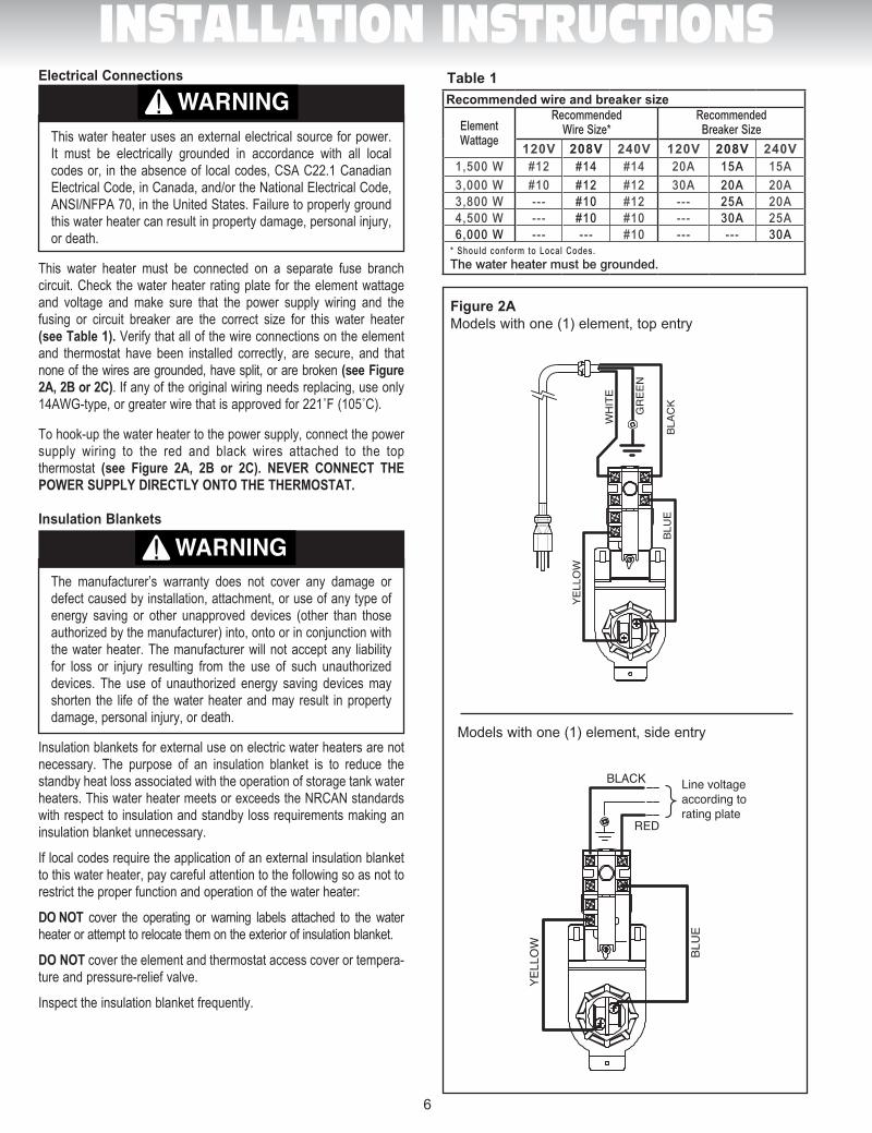
INSTALLATION INSTRUCTIONSElectrical Connections
This water heater uses an external electrical source for power. It must be electrically grounded in accordance with all local codes or, in the absence of local codes, CSA C22.1 Canadian Electrical Code, in Canada, and/or the National Electrical Code, ANSI/NFPA 70, in the United States. Failure to properly ground this water heater can result in property damage, personal injury, or death.
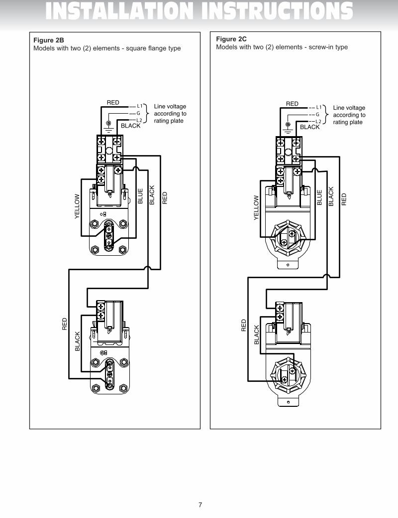
This water heater must be connected on a separate fuse branch circuit. Check the water heater rating plate for the element wattage and voltage and make sure that the power supply wiring and the fusing or circuit breaker are the correct size for this water heater (see Table 1). Verify that all of the wire connections on the element and thermostat have been installed correctly, are secure, and that none of the wires are grounded, have split, or are broken (see Figure 2A, 2B or 2C). If any of the original wiring needs replacing, use only 14AWG-type,orgreaterwirethatisapprovedfor221˚F(105˚C).
To hook-up the water heater to the power supply, connect the power supply wiring to the red and black wires attached to the top thermostat (see Figure 2A, 2B or 2C). NEVER CONNECT THE POWER SUPPLY DIRECTLY ONTO THE THERMOSTAT.
Insulation Blankets
The manufacturer’s warranty does not cover any damage or defect caused by installation, attachment, or use of any type of energy saving or other unapproved devices (other than those authorized by the manufacturer) into, onto or in conjunction with the water heater. The manufacturer will not accept any liability for loss or injury resulting from the use of such unauthorized devices. The use of unauthorized energy saving devices may shorten the life of the water heater and may result in property damage, personal injury, or death.
Insulation blankets for external use on electric water heaters are not necessary. The purpose of an insulation blanket is to reduce the standby heat loss associated with the operation of storage tank water heaters. This water heater meets or exceeds the NRCAN standards with respect to insulation and standby loss requirements making an insulation blanket unnecessary.
If local codes require the application of an external insulation blanket to this water heater, pay careful attention to the following so as not to restrict the proper function and operation of the water heater:
DO NOT cover the operating or warning labels attached to the water heater or attempt to relocate them on the exterior of insulation blanket.
DO NOT cover the element and thermostat access cover or tempera-ture and pressure-relief valve.
Inspect the insulation blanket frequently.
WARNING
AVERTISSEMENT
DANGER
WARNING
AVERTISSEMENT
DANGER
BLU
E
YELL
OW
BLAC
K
WH
ITE
BLEU
JAU
NE
NO
IRBLAN
C
BLU
E
YELL
OW BLEU
JAU
NE
VER
T
GR
EEN
NOIR
ROUGE
Voltageselon plaquesignalétique
Line voltageaccording torating plate
BLACK
RED
BLU
E
YELL
OW
BLAC
K
WH
ITE
BLEU
JAU
NE
NO
IRBLAN
C
BLU
E
YELL
OW BLEU
JAU
NE
VER
T
GR
EEN
NOIR
ROUGE
Voltageselon plaquesignalétique
Line voltageaccording torating plate
BLACK
RED
Models with one (1) element, side entry
Figure 2AModels with one (1) element, top entry
Recommended wire and breaker size
ElementWattage
RecommendedWire Size*
RecommendedBreaker Size
120V 208V 240V 120V 208V 240V1,500 W #12 #14 #14 20A 15A 15A3,000 W #10 #12 #12 30A 20A 20A3,800 W --- #10 #12 --- 25A 20A4,500 W --- #10 #10 --- 30A 25A6,000 W --- --- #10 --- --- 30A
* Should conform to Local Codes. The water heater must be grounded.
Table 1
Man Electrique-GI-IM017Bi-1211.indd 7 11-12-21 12:30 PM
7
INSTALLATION INSTRUCTIONSFigure 2CModels with two (2) elements - screw-in type
L1G L2
L1G L2
BLU
EBL
UE
BLAC
K
BLAC
KBL
ACK
BLAC
KR
ED
RED
RED
YELL
OW
YELL
OW
BLEU
NO
IR
NO
IR
RO
UG
E
RO
UG
E
JAU
NEBL
UE
BLAC
K
BLAC
KBL
ACK
BLAC
K
RED
RED
YELL
OW
BLEU
NO
IR
NO
IRN
OIR
NO
IR
RO
UG
E
RO
UG
E
JAU
NE
BLEU
NO
IR
NO
IR
RO
UG
E
JAU
NE
BLU
EBL
UE
BLAC
K
BLAC
KBL
ACK
BLAC
KR
ED
RED
RED
YELL
OW
YELL
OW
BLEU
NO
IR
NO
IR
NOIR
RO
UG
E
RO
UG
E
ROUGE
JAU
NE
BLEU
NO
IR
NO
IR
RO
UG
E
JAU
NE
NOIR
ROUGE
Série 59T
Série AW
L1G L2
NOIR
ROUGEL1G L2
BLACK
REDL1G L2
BLACK
REDL1G L2
NOIR
ROUGEL1G L2
BLACK
RED
L1G L2
NOIR
ROUGEL1G L2
BLACK
REDL1G L2
BLACK
RED
BLAC
K
RED
NO
IR
RO
UG
E
Voltageselon plaquesignalétique
Line voltageaccording torating plate
Voltageselon plaquesignalétique
Line voltageaccording torating plate
Voltageselon plaquesignalétique
Line voltageaccording torating plate
Voltageselon plaquesignalétique
Line voltageaccording torating plate
Voltageselon plaquesignalétique
Line voltageaccording torating plate
Figure 2B Models with two (2) elements - square flange type
L1G L2
L1G L2
BLU
EBL
UE
BLAC
K
BLAC
KBL
ACK
BLAC
KR
ED
RED
RED
YELL
OW
YELL
OW
BLEU
NO
IR
NO
IR
RO
UG
E
RO
UG
E
JAU
NEBL
UE
BLAC
K
BLAC
KBL
ACK
BLAC
K
RED
RED
YELL
OW
BLEU
NO
IR
NO
IRN
OIR
NO
IR
RO
UG
E
RO
UG
E
JAU
NE
BLEU
NO
IR
NO
IR
RO
UG
E
JAU
NE
BLU
EBL
UE
BLAC
K
BLAC
KBL
ACK
BLAC
KR
ED
RED
RED
YELL
OW
YELL
OW
BLEU
NO
IR
NO
IR
NOIR
RO
UG
E
RO
UG
E
ROUGE
JAU
NE
BLEU
NO
IR
NO
IR
RO
UG
E
JAU
NE
NOIR
ROUGE
Série 59T
Série AW
L1G L2
NOIR
ROUGEL1G L2
BLACK
REDL1G L2
BLACK
REDL1G L2
NOIR
ROUGEL1G L2
BLACK
RED
L1G L2
NOIR
ROUGEL1G L2
BLACK
REDL1G L2
BLACK
RED
BLAC
K
RED
NO
IR
RO
UG
E
Voltageselon plaquesignalétique
Line voltageaccording torating plate
Voltageselon plaquesignalétique
Line voltageaccording torating plate
Voltageselon plaquesignalétique
Line voltageaccording torating plate
Voltageselon plaquesignalétique
Line voltageaccording torating plate
Voltageselon plaquesignalétique
Line voltageaccording torating plate
Man Electrique-GI-IM017Bi-1211.indd 8 11-12-21 12:30 PM
8
OPERATING INSTRUCTIONS
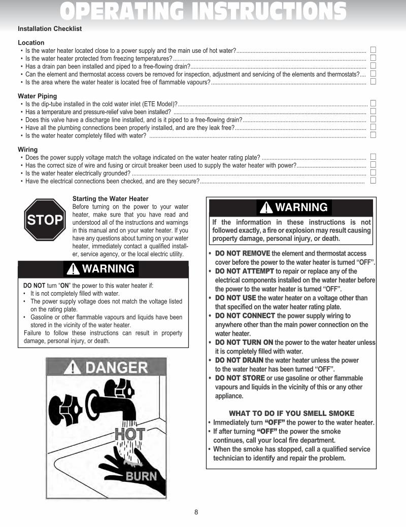
Starting the Water HeaterBefore turning on the power to your water heater, make sure that you have read and understood all of the instructions and warnings in this manual and on your water heater. If you have any questions about turning on your water heater, immediately contact a qualified install-er, service agency, or the local electric utility.
DO NOT turn “ON” the power to this water heater if:• Itisnotcompletelyfilledwithwater.• Thepowersupplyvoltagedoesnotmatchthevoltagelisted
on the rating plate.• Gasolineorotherflammablevapoursandliquidshavebeen
stored in the vicinity of the water heater.Failure to follow these instructions can result in property damage, personal injury, or death.
WARNING
AVERTISSEMENT
DANGER
Installation Checklist
Location • Isthewaterheaterlocatedclosetoapowersupplyandthemainuseofhotwater? .................................................................................. L • Isthewaterheaterprotectedfromfreezingtemperatures? .......................................................................................................................... L • Hasadrainpanbeeninstalledandpipedtoafree-flowingdrain? ............................................................................................................... L • Cantheelementandthermostataccesscoversberemovedforinspection,adjustmentandservicingoftheelementsandthermostats? .... L • Istheareawherethewaterheaterislocatedfreeofflammablevapours? .................................................................................................. L
Water Piping • Isthedip-tubeinstalledinthecoldwaterinlet(ETEModel)? ........................................................................................................................ L • Hasatemperatureandpressure-reliefvalvebeeninstalled? ................................................................................................................................... L • Doesthisvalvehaveadischargelineinstalled,andisitpipedtoafree-flowingdrain? .............................................................................. L • Havealltheplumbingconnectionsbeenproperlyinstalled,andaretheyleakfree? ................................................................................... L • Isthewaterheatercompletelyfilledwithwater? ......................................................................................................................................... L
Wiring • Doesthepowersupplyvoltagematchthevoltageindicatedonthewaterheaterratingplate? .................................................................. L • Hasthecorrectsizeofwireandfusingorcircuitbreakerbeenusedtosupplythewaterheaterwithpower? ............................................ L • Isthewaterheaterelectricallygrounded? .................................................................................................................................................... L • Havetheelectricalconnectionsbeenchecked,andaretheysecure? ........................................................................................................ L
WARNING
AVERTISSEMENT
DANGERIf the information in these instructions is not followed exactly, a fire or explosion may result causing property damage, personal injury, or death.
• DO NOT REMOVE the element and thermostat access cover before the power to the water heater is turned “OFF”.
• DO NOT ATTEMPT to repair or replace any of the electrical components installed on the water heater before the power to the water heater is turned “OFF”.
• DO NOT USE the water heater on a voltage other than that specified on the water heater rating plate.
• DO NOT CONNECT the power supply wiring to anywhere other than the main power connection on the water heater.
• DO NOT TURN ON the power to the water heater unless it is completely filled with water.
• DO NOT DRAIN the water heater unless the power to the water heater has been turned “OFF”.
• DO NOT STORE or use gasoline or other flammable vapours and liquids in the vicinity of this or any other appliance.
WHAT TO DO IF YOU SMELL SMOKE• Immediatelyturn “OFF” the power to the water heater.• Ifafterturning “OFF” the power the smoke
continues, call your local fire department.• Whenthesmokehasstopped,callaqualifiedservice
technician to identify and repair the problem.
Man Electrique-GI-IM017Bi-1211.indd 9 11-12-21 12:30 PM
9
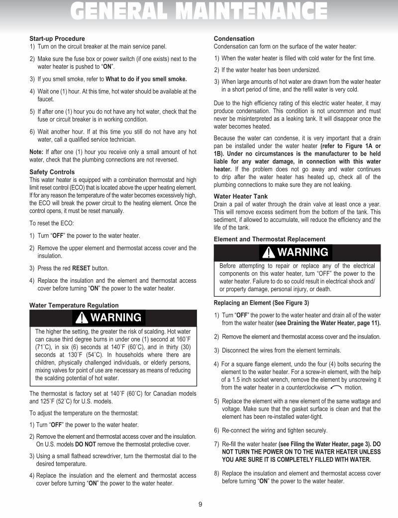
GENERAL MAINTENANCEStart-up Procedure1) Turn on the circuit breaker at the main service panel.
2) Make sure the fuse box or power switch (if one exists) next to the water heater is pushed to “ON”.
3) If you smell smoke, refer to What to do if you smell smoke.
4) Wait one (1) hour. At this time, hot water should be available at the faucet.
5) If after one (1) hour you do not have any hot water, check that the fuse or circuit breaker is in working condition.
6) Wait another hour. If at this time you still do not have any hot water, call a qualified service technician.
Note: If after one (1) hour you receive only a small amount of hot water, check that the plumbing connections are not reversed.
Safety ControlsThis water heater is equipped with a combination thermostat and high limit reset control (ECO) that is located above the upper heating element. If for any reason the temperature of the water becomes excessively high, the ECO will break the power circuit to the heating element. Once the control opens, it must be reset manually.
To reset the ECO:
1) Turn “OFF” the power to the water heater.
2) Remove the upper element and thermostat access cover and the insulation.
3) Press the red RESET button.
4) Replace the insulation and the element and thermostat access cover before turning “ON” the power to the water heater.
Water Temperature Regulation
The higher the setting, the greater the risk of scalding. Hot water cancausethirddegreeburnsinunderone(1)secondat160˚F(71˚C), in six (6) seconds at 140˚F (60˚C), and in thirty (30) seconds at 130˚F (54˚C). In households where there are children, physically challenged individuals, or elderly persons, mixing valves for point of use are necessary as means of reducing the scalding potential of hot water.
The thermostat is factory setat140˚F (60˚C) forCanadianmodelsand125˚F(52˚C)forU.S.models.
To adjust the temperature on the thermostat:
1) Turn “OFF” the power to the water heater.
2) Remove the element and thermostat access cover and the insulation. On U.S. models DO NOT remove the thermostat protective cover.
3) Using a small flathead screwdriver, turn the thermostat dial to the desired temperature.
4) Replace the insulation and the element and thermostat access cover before turning “ON” the power to the water heater.
CondensationCondensation can form on the surface of the water heater:
1) When the water heater is filled with cold water for the first time.
2) If the water heater has been undersized.
3) When large amounts of hot water are drawn from the water heater in a short period of time, and the refill water is very cold.
Due to the high efficiency rating of this electric water heater, it may produce condensation. This condition is not uncommon and must never be misinterpreted as a leaking tank. It will disappear once the water becomes heated.
Because the water can condense, it is very important that a drain pan be installed under the water heater (refer to Figure 1A or 1B). Under no circumstances is the manufactu rer to be held liable for any water damage, in connection with this water heater. If the problem does not go away and water continues to drip after the water heater has heated up, check all of the plumbing connections to make sure they are not leaking.
Water Heater TankDrain a pail of water through the drain valve at least once a year. This will remove excess sediment from the bottom of the tank. This sediment, if allowed to accumulate, will reduce the efficiency and the life of the tank.
Element and Thermostat Replacement
Before attempting to repair or replace any of the electrical components on this water heater, turn “OFF” the power to the water heater. Failure to do so could result in electrical shock and/or property damage, personal injury, or death.
Replacing an Element (See Figure 3)
1) Turn “OFF” the power to the water heater and drain all of the water from the water heater (see Draining the Water Heater, page 11).
2) Remove the element and thermostat access cover and the insulation.
3) Disconnect the wires from the element terminals.
4) For a square flange element, undo the four (4) bolts securing the element to the water heater. For a screw-in element, with the help of a 1.5 inch socket wrench, remove the element by unscrewing it from the water heater in a counterclockwise motion.
5) Replace the element with a new element of the same wattage and voltage. Make sure that the gasket surface is clean and that the element has been re-installed water-tight.
6) Re-connect the wiring and tighten securely.
7) Re-fill the water heater (see Filing the Water Heater, page 3). DO NOT TURN THE POWER ON TO THE WATER HEATER UNLESS YOU ARE SURE IT IS COMPLETELY FILLED WITH WATER.
8) Replace the insulation and element and thermostat access cover before turning “ON” the power to the water heater.
WARNING
AVERTISSEMENT
DANGER
WARNING
AVERTISSEMENT
DANGER
Man Electrique-GI-IM017Bi-1211.indd 10 11-12-21 12:30 PM
10
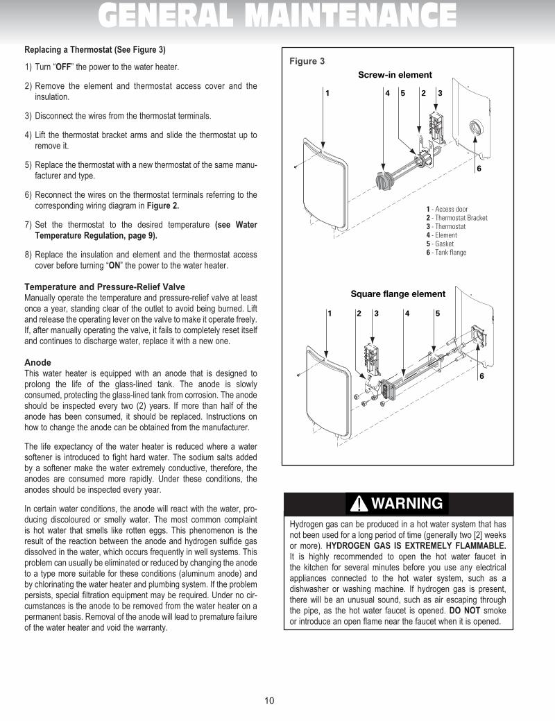
GENERAL MAINTENANCEReplacing a Thermostat (See Figure 3)
1) Turn “OFF” the power to the water heater.
2) Remove the element and thermostat access cover and the insulation.
3) Disconnect the wires from the thermostat terminals.
4) Lift the thermostat bracket arms and slide the thermostat up to remove it.
5) Replace the thermostat with a new thermostat of the same manu-facturer and type.
6) Reconnect the wires on the thermostat terminals referring to the corresponding wiring diagram in Figure 2.
7) Set the thermostat to the desired temperature (see Water Temperature Regulation, page 9).
8) Replace the insulation and element and the thermostat access cover before turning “ON” the power to the water heater.
Temperature and Pressure-Relief ValveManually operate the temperature and pressure-relief valve at least once a year, standing clear of the outlet to avoid being burned. Lift and release the operating lever on the valve to make it operate freely. If, after manually operating the valve, it fails to completely reset itself and continues to discharge water, replace it with a new one.
AnodeThis water heater is equipped with an anode that is designed to prolong the life of the glass-lined tank. The anode is slowly consumed, protecting the glass-lined tank from corrosion. The anode should be inspected every two (2) years. If more than half of the anode has been consumed, it should be replaced. Instructions on how to change the anode can be obtained from the manufacturer.
The life expectancy of the water heater is reduced where a water softener is introduced to fight hard water. The sodium salts added by a softener make the water extremely conductive, therefore, the anodes are consumed more rapidly. Under these conditions, the anodes should be inspected every year.
In certain water conditions, the anode will react with the water, pro-ducing discoloured or smelly water. The most common complaint is hot water that smells like rotten eggs. This phenomenon is the result of the reaction between the anode and hydrogen sulfide gas dissolved in the water, which occurs frequently in well systems. This problem can usually be eliminated or reduced by changing the anode to a type more suitable for these conditions (aluminum anode) and by chlorinating the water heater and plumbing system. If the problem persists, special filtration equipment may be required. Under no cir-cumstances is the anode to be removed from the water heater on a permanent basis. Removal of the anode will lead to premature failure of the water heater and void the warranty.
Hydrogen gas can be produced in a hot water system that has not been used for a long period of time (generally two [2] weeks or more). HYDROGEN GAS IS EXTREMELY FLAMMABLE. It is highly recommended to open the hot water faucet in the kitchen for several minutes before you use any electrical appliances connected to the hot water system, such as a dishwasher or washing machine. If hydrogen gas is present, there will be an unusual sound, such as air escaping through the pipe, as the hot water faucet is opened. DO NOT smoke or introduce an open flame near the faucet when it is opened.
Square flange element Square flange element
1 2 3 4 5
6
1 - Access door2 - Thermostat Bracket3 - Thermostat4 - Element5 - Gasket6 - Tank flange
Screw-in element
1 4 5 2 3
6
1 2 3 4 5
6
1 - Porte d'accès2 - Support du thermostat3 - Thermostat4 - Élément 5 - Joint d'étanchéité 6 - Bride du réservoir
Screw-in element
1 4 5 2 3
6
Figure 3
WARNING
AVERTISSEMENT
DANGER
Man Electrique-GI-IM017Bi-1211.indd 11 11-12-21 12:30 PM
Draining the Water HeaterTo completely drain the water heater:
1) Turn “OFF” the power to the water heater.
2) Close the cold water supply manual shut-off valve.
3) Connect one end of a garden hose to the water heater drain valve and put the other end next to a free-flowing drain.
4) Open the drain valve by inserting a flat head screwdriver into the slot on the head of the drain valve and turning the knob counterclockwise .
5) Open a hot water faucet to allow air into the system.
VacationIf you are planning a vacation or other prolonged absence, it is highly recommended to turn “OFF” the power to the water heater and the cold water supply to the water heater. This will save energy, protect against property damage in the event the water heater leaks, and prevent the build-up of hydrogen gas. If the water heater and piping are exposed to freezing temperatures, they should both be drained. Remember to check the water heater thoroughly after it has been shut off for an extended period of time before putting it back in operation. Make sure that the water heater is completely full of water, and that the cold water supply manual shut-off valve is open, before turning “ON” the power to the water heater.
Getting Service for your Water HeaterIf you are having problems with your water heater, follow these three easy steps:
1) Read the Troubleshooting Guide contained in this manual (see Page 14). It lists the most common problems experienced with your electric water heater. The solutions you find listed may provide a quick and simple solution to your problem and save you time and money.
2) If the solution listed in the Troubleshooting Guide does not solve the problem or if your particular problem is not listed in the guide, contact the installer of the water heater, or the local electric utility.
3) If you still cannot solve the problem, contact the manufacturer’s Customer Service Department by e-mail at [email protected] or by telephone at 1-800-363-9354. To help serve you in a quick and efficient manner, always have the following information ready:
a) Model number. b) Serial number. c) Date of installation. d) Where the water heater was purchased. e) Complete address where the water heater is installed. f) A description of the problem.
11
GENERAL MAINTENANCE
Man Electrique-GI-IM017Bi-1211.indd 12 11-12-21 12:30 PM
12
REPLACEMENT PARTS
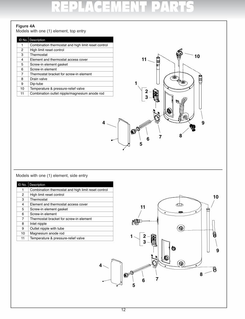
ID No. Description 1 Check valve, water meter or pressure reducing valve 2 Cold water manual shut-off valve 3 Union 4 Cold water intlet 5 Temperature & pressure-relief valve 6 Expansion tank 7 Overflow tube 8 Dip-tube 9 Drain pan 10 Free-flowing floor drain 11 Lower element 12 Drain valve 13 Element and thermostat access covers 14 Lower thermostat 15 Magnesium anode rod 16 Upper element 17 Combination upper thermostat and high limit reset control 18 Hot water outlet 19 Union 20 Hot water manual shut-off valve
1234519
20
1
13
14
3
2a2b
13
12a
2b
34
5678
9
10
11
12
14
15
6
7
9
10
1112
13 14
17
18
15
16
8
1234519
20
6
7
9
10
1112
13 14
17
18
15
16
8
ID No. Description 1 Check valve, water meter or pressure reducing valve 2 Cold water manual shut-off valve 3 Union 4 Vacuum breaker 5 Temperature & pressure-relief valve 6 Expansion tank 7 Overflow tube 8 Drain pan 9 Free-flowing floor drain 10 Cold water intlet 11 Lower element 12 Drain valve 13 Element and thermostat access covers 14 Lower thermostat 15 Magnesium anode rod 16 Upper element 17 Combination upper thermostat and high limit reset control 18 Hot water outlet 19 Union 20 Hot water manual shut-off valve
ID No. Description 1 Upper thermostat with reset 2a High limit reset control 2b Upper thermostat 3 Element gasket 4 Upper element 5 Drain valve 6 Lower Thermostat 7 Thermostat bracket 8 Machine bolt & hex head nut 9 Element and thermostat access cover 10 Lower element 11 Dip tube 12 Magnesium anode rod 13 Extention fitting 14 Outlet nipple 15 Temperature & pressure-relief Valve
ID No. Description 1 Upper thermostat with reset 2a High limit reset control 2b Upper thermostat 3 Element gasket 4 Upper element 5 Drain valve 6 Lower Thermostat 7 Thermostat bracket 8 Machine bolt & hex head nut 9 Element and thermostat access cover 10 Lower element 11 Inlet nipple 12 Magnesium anode rod 13 Outlet nipple 14 Brass “T” 15 Temperature & pressure-relief Valve 4
5
9
6
10
11
127
8
1
14
3
2a2b
45
9
6
10
11
127
8
Num. Description 1 Thermostat du haut avec interrupteur secondaire 2a Interrupteur secondaire 2b Thermostat du haut 3 Joint d’étanchéité pour élément 4 Élément du haut 5 Robinet de vidange 6 Thermostat du bas 7 Support pour thermostat 8 Vis et écrou 9 Porte d’accès aux éléments et thermostats 10 Élément du bas 11 Raccord d’entrée 12 Anode de magnésium 13 Raccord de sortie 14 «T» en laiton 15 Soupape température et pression
Num. Description 1 Thermostat du haut avec interrupteur secondaire 2a Interrupteur secondaire 2b Thermostat du haut 3 Joint d’étanchéité pour élément 4 Élément du haut 5 Robinet de vidange 6 Thermostat du bas 7 Support pour thermostat 8 Vis et écrou 9 Porte d’accès aux éléments et thermostats 10 Élément du bas 11 Tuyau plongeur 12 Anode de magnésium 13 Raccord de rallonge 14 Raccord de sortie 15 Soupape température et pression
Num. Description 1 Compteur d’eau ou clapet ou soupape de réduction de pression 2 Robinet d’arrêt d’eau froide manuel 3 Raccord 4 Brise vide 5 Soupape de sécurité de température et pression 6 Réservoir d’expansion 7 Tuyau d’évacuation 8 Bassin de rétention 9 Drain de plancher 10 Entrée d’eau froide 11 Élément du bas 12 Robinet de vidange 13 Portes d’accès aux éléments et thermostats 14 Thermostat du bas 15 Anode de magnésium 16 Élément du haut 17 Thermosat du haut avec interrupteur secondaire 18 Sortie d’eau chaude 19 Raccord 20 Robinet d’arrêt d’eau chaude manuel
Num. Description 1 Compteur d’eau ou clapet ou soupape de réduction de pression 2 Robinet d’arrêt d’eau froide manuel 3 Raccord 4 Entrée d’eau froide 5 Soupape de sécurité de température et pression 6 Réservoir d’expansion 7 Tuyau d’évacuation 8 Tuyau plongeur 9 Bassin de rétention 10 Drain de plancher 11 Élément du bas 12 Robinet de vidange 13 Portes d’accès aux éléments et thermostats 14 Thermostat du bas 15 Anode de magnésium 16 Élément du haut 17 Thermosat du haut avec interrupteur secondaire 18 Sortie d’eau chaude 19 Raccord 20 Robinet d’arrêt d’eau chaude manuel
13
12a
2b
34
5678
9
10
11
12
1
6
7
8
9
101112
23
45
1920
13
141516
17
1
6
7
8
9
101112
23
45
1920
18
18
13
141516
17
16
15
1413
11
121
2
45
6
3
7
17
18
9
10
8
3
2 1
16 15 14
13
11
108
76
9
4
5 12
1718
3
2 1
16 15 14
13
11
108
76
9
4
5 12
1718
Num. Description 1) Sortie d’eau chaude 2) Raccord 3) Robinet d’arrêt d’eau chaude manuel 4) Soupape de sûreté de température et pression 5) Raccord de sortie/anode de magnésium combinés 6) Thermostat avec interrupteur secondaire 7) Porte d’accès à l’élément et au thermostat 8) Élément vissé 9) Robinet de vidange 10) Drain de plancher 11) Bassin de rétention 12) Réservoir d’expansion 13) Tuyau plongeur 14) Compteur d’eau ou clapet ou soupape de réduction de pression 15) Robinet d’arrêt d’eau froide manuel 16) Tuyau d’évacuation 17) Raccord 18) Entrée d’eau froide
ID No. Description 1) Hot water outlet 2) Union 3) Hot water manual shut-off valve 4) Temperature & pressure-relief valve 5) Combination outlet nipple/ magnesium anode rod 6) Combination thermostat and high limit reset control 7) Element and thermostat access cover 8) Screw-in element 9) Drain valve 10) Free-flowing floor drain 11) Drain pan 12) Expansion tank 13) Dip-tube 14) Check valve, water meter or pressure reducing valve 15) Cold water manual shut-off valve 16) Overflow tube 17) Union 18) Cold water intlet
Num. Description 1) Tuyau de sortie 2) Soupape de sûreté de température et pression 3) Tuyau d’évacuation 4) Anode 5) Thermostat avec interrupteur secondaire 6) Élément vissé 7) Porte d’accès à l’élément et au thermostat 8) Drain de plancher 9) Robinet de vidange 10) Bassin de rétention 11) Réservoir d’expansion 12) Compteur d’eau ou clapet ou soupape de réduction de pression 13) Entrée d’eau froide 14) Robinet d’arrêt d’eau froide manuel 15) Raccords 16) Sortie d’eau chaude 17) Brise vide 18) Robinet d’arrêt d’eau chaude manuel
ID No. Description 1) Outlet tube
2) Temperature & pressure-relief valve 3) Over�ow tube 4) Magnesium anode rod 5) Combination thermostat and high limit reset control 6) Screw-in element 7) Element and thermostat access cover 8) Free-�owing �oor drain 9) Drain valve 10) Drain pan 11) Expansion tank 12) Check valve, water meter or pressure reducing valve 13) Cold water inlet 14) Cold water manual shut-off valve 15) Unions 16) Hot water outlet 17) Vacuum breaker 18) Hot water manual shut-off valve
16
15
1413
11
121
2
45
6
3
7
17
18
9
10
8
9 4 7 1
13 16 17
9 4 7 1
ID No. Description 1 Combination thermostat and high limit reset control 2 High limit reset control 3 Thermostat 4 Element and thermostat access cover 5 Screw-in element gasket 6 Screw-in element 7 Thermostat bracket for screw-in element 8 Drain valve 9 Dip-tube 10 Temperature & pressure-relief valve 11 Combination outlet nipple/magnesium anode rod
123
4
56 7 8
9
1011
ID No. Description 1 Combination thermostat and high limit reset control 2 High limit reset control 3 Thermostat 4 Element and thermostat access cover 5 Screw-in element gasket 6 Screw-in element 7 Thermostat bracket for screw-in element 8 Inlet nipple 9 Outlet nipple with tube 10 Magnesium anode rod 11 Temperature & pressure-relief valve 1 2
3
4
56 7
8
9
10
11
ID No. Description 1 Thermostat avec interrupteur secondaire 2 Interrupteur secondaire 3 Thermostat 4 Porte d’accès à l’élément et au thermostat 5 Joint d’étanchéité pour élément vissé 6 Élément vissé 7 Support pour thermostat avec élément vissé 8 Robinet de vidange 9 Tuyau plongeur 10 Soupape de sûreté de température et pression 11 Raccord de sortie/anode de magnésium combiné
Num. Description 1 Thermostat avec interrupteur secondaire 2 Interrupteur secondaire 3 Thermostat 4 Porte d’accès à l’élément et au thermostat 5 Joint d’étanchéité pour élément vissé 6 Élément vissé 7 Support pour thermostat avec élément vissé 8 Raccord d’entrée 9 Raccord de sortie avec tuyau 10 Anode de magnésium 11 Soupape de sûreté de température et pression 1 2
3
4
56 7
8
9
10
11
123
4
56 7 8
9
1011
13 16 17
14
15
15
13
15
Figure 4AModels with one (1) element, top entry
Models with one (1) element, side entry
Man Electrique-GI-IM017Bi-1211.indd 13 11-12-21 12:30 PM
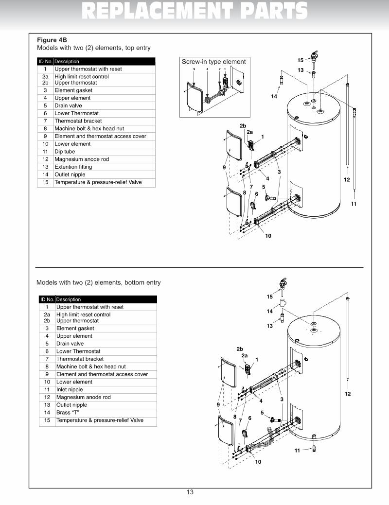
13
REPLACEMENT PARTS
ID No. Description 1 Check valve, water meter or pressure reducing valve 2 Cold water manual shut-off valve 3 Union 4 Cold water intlet 5 Temperature & pressure-relief valve 6 Expansion tank 7 Overflow tube 8 Dip-tube 9 Drain pan 10 Free-flowing floor drain 11 Lower element 12 Drain valve 13 Element and thermostat access covers 14 Lower thermostat 15 Magnesium anode rod 16 Upper element 17 Combination upper thermostat and high limit reset control 18 Hot water outlet 19 Union 20 Hot water manual shut-off valve
1234519
20
1
13
14
3
2a2b
13
12a
2b
34
5678
9
10
11
12
14
15
6
7
9
10
1112
13 14
17
18
15
16
8
1234519
20
6
7
9
10
1112
13 14
17
18
15
16
8
ID No. Description 1 Check valve, water meter or pressure reducing valve 2 Cold water manual shut-off valve 3 Union 4 Vacuum breaker 5 Temperature & pressure-relief valve 6 Expansion tank 7 Overflow tube 8 Drain pan 9 Free-flowing floor drain 10 Cold water intlet 11 Lower element 12 Drain valve 13 Element and thermostat access covers 14 Lower thermostat 15 Magnesium anode rod 16 Upper element 17 Combination upper thermostat and high limit reset control 18 Hot water outlet 19 Union 20 Hot water manual shut-off valve
ID No. Description 1 Upper thermostat with reset 2a High limit reset control 2b Upper thermostat 3 Element gasket 4 Upper element 5 Drain valve 6 Lower Thermostat 7 Thermostat bracket 8 Machine bolt & hex head nut 9 Element and thermostat access cover 10 Lower element 11 Dip tube 12 Magnesium anode rod 13 Extention fitting 14 Outlet nipple 15 Temperature & pressure-relief Valve
ID No. Description 1 Upper thermostat with reset 2a High limit reset control 2b Upper thermostat 3 Element gasket 4 Upper element 5 Drain valve 6 Lower Thermostat 7 Thermostat bracket 8 Machine bolt & hex head nut 9 Element and thermostat access cover 10 Lower element 11 Inlet nipple 12 Magnesium anode rod 13 Outlet nipple 14 Brass “T” 15 Temperature & pressure-relief Valve 4
5
9
6
10
11
127
8
1
14
3
2a2b
45
9
6
10
11
127
8
Num. Description 1 Thermostat du haut avec interrupteur secondaire 2a Interrupteur secondaire 2b Thermostat du haut 3 Joint d’étanchéité pour élément 4 Élément du haut 5 Robinet de vidange 6 Thermostat du bas 7 Support pour thermostat 8 Vis et écrou 9 Porte d’accès aux éléments et thermostats 10 Élément du bas 11 Raccord d’entrée 12 Anode de magnésium 13 Raccord de sortie 14 «T» en laiton 15 Soupape température et pression
Num. Description 1 Thermostat du haut avec interrupteur secondaire 2a Interrupteur secondaire 2b Thermostat du haut 3 Joint d’étanchéité pour élément 4 Élément du haut 5 Robinet de vidange 6 Thermostat du bas 7 Support pour thermostat 8 Vis et écrou 9 Porte d’accès aux éléments et thermostats 10 Élément du bas 11 Tuyau plongeur 12 Anode de magnésium 13 Raccord de rallonge 14 Raccord de sortie 15 Soupape température et pression
Num. Description 1 Compteur d’eau ou clapet ou soupape de réduction de pression 2 Robinet d’arrêt d’eau froide manuel 3 Raccord 4 Brise vide 5 Soupape de sécurité de température et pression 6 Réservoir d’expansion 7 Tuyau d’évacuation 8 Bassin de rétention 9 Drain de plancher 10 Entrée d’eau froide 11 Élément du bas 12 Robinet de vidange 13 Portes d’accès aux éléments et thermostats 14 Thermostat du bas 15 Anode de magnésium 16 Élément du haut 17 Thermosat du haut avec interrupteur secondaire 18 Sortie d’eau chaude 19 Raccord 20 Robinet d’arrêt d’eau chaude manuel
Num. Description 1 Compteur d’eau ou clapet ou soupape de réduction de pression 2 Robinet d’arrêt d’eau froide manuel 3 Raccord 4 Entrée d’eau froide 5 Soupape de sécurité de température et pression 6 Réservoir d’expansion 7 Tuyau d’évacuation 8 Tuyau plongeur 9 Bassin de rétention 10 Drain de plancher 11 Élément du bas 12 Robinet de vidange 13 Portes d’accès aux éléments et thermostats 14 Thermostat du bas 15 Anode de magnésium 16 Élément du haut 17 Thermosat du haut avec interrupteur secondaire 18 Sortie d’eau chaude 19 Raccord 20 Robinet d’arrêt d’eau chaude manuel
13
12a
2b
34
5678
9
10
11
12
1
6
7
8
9
101112
23
45
1920
13
141516
17
1
6
7
8
9
101112
23
45
1920
18
18
13
141516
17
16
15
1413
11
121
2
45
6
3
7
17
18
9
10
8
3
2 1
16 15 14
13
11
108
76
9
4
5 12
1718
3
2 1
16 15 14
13
11
108
76
9
4
5 12
1718
Num. Description 1) Sortie d’eau chaude 2) Raccord 3) Robinet d’arrêt d’eau chaude manuel 4) Soupape de sûreté de température et pression 5) Raccord de sortie/anode de magnésium combinés 6) Thermostat avec interrupteur secondaire 7) Porte d’accès à l’élément et au thermostat 8) Élément vissé 9) Robinet de vidange 10) Drain de plancher 11) Bassin de rétention 12) Réservoir d’expansion 13) Tuyau plongeur 14) Compteur d’eau ou clapet ou soupape de réduction de pression 15) Robinet d’arrêt d’eau froide manuel 16) Tuyau d’évacuation 17) Raccord 18) Entrée d’eau froide
ID No. Description 1) Hot water outlet 2) Union 3) Hot water manual shut-off valve 4) Temperature & pressure-relief valve 5) Combination outlet nipple/ magnesium anode rod 6) Combination thermostat and high limit reset control 7) Element and thermostat access cover 8) Screw-in element 9) Drain valve 10) Free-flowing floor drain 11) Drain pan 12) Expansion tank 13) Dip-tube 14) Check valve, water meter or pressure reducing valve 15) Cold water manual shut-off valve 16) Overflow tube 17) Union 18) Cold water intlet
Num. Description 1) Tuyau de sortie 2) Soupape de sûreté de température et pression 3) Tuyau d’évacuation 4) Anode 5) Thermostat avec interrupteur secondaire 6) Élément vissé 7) Porte d’accès à l’élément et au thermostat 8) Drain de plancher 9) Robinet de vidange 10) Bassin de rétention 11) Réservoir d’expansion 12) Compteur d’eau ou clapet ou soupape de réduction de pression 13) Entrée d’eau froide 14) Robinet d’arrêt d’eau froide manuel 15) Raccords 16) Sortie d’eau chaude 17) Brise vide 18) Robinet d’arrêt d’eau chaude manuel
ID No. Description 1) Outlet tube
2) Temperature & pressure-relief valve 3) Over�ow tube 4) Magnesium anode rod 5) Combination thermostat and high limit reset control 6) Screw-in element 7) Element and thermostat access cover 8) Free-�owing �oor drain 9) Drain valve 10) Drain pan 11) Expansion tank 12) Check valve, water meter or pressure reducing valve 13) Cold water inlet 14) Cold water manual shut-off valve 15) Unions 16) Hot water outlet 17) Vacuum breaker 18) Hot water manual shut-off valve
16
15
1413
11
121
2
45
6
3
7
17
18
9
10
8
9 4 7 1
13 16 17
9 4 7 1
ID No. Description 1 Combination thermostat and high limit reset control 2 High limit reset control 3 Thermostat 4 Element and thermostat access cover 5 Screw-in element gasket 6 Screw-in element 7 Thermostat bracket for screw-in element 8 Drain valve 9 Dip-tube 10 Temperature & pressure-relief valve 11 Combination outlet nipple/magnesium anode rod
123
4
56 7 8
9
1011
ID No. Description 1 Combination thermostat and high limit reset control 2 High limit reset control 3 Thermostat 4 Element and thermostat access cover 5 Screw-in element gasket 6 Screw-in element 7 Thermostat bracket for screw-in element 8 Inlet nipple 9 Outlet nipple with tube 10 Magnesium anode rod 11 Temperature & pressure-relief valve 1 2
3
4
56 7
8
9
10
11
ID No. Description 1 Thermostat avec interrupteur secondaire 2 Interrupteur secondaire 3 Thermostat 4 Porte d’accès à l’élément et au thermostat 5 Joint d’étanchéité pour élément vissé 6 Élément vissé 7 Support pour thermostat avec élément vissé 8 Robinet de vidange 9 Tuyau plongeur 10 Soupape de sûreté de température et pression 11 Raccord de sortie/anode de magnésium combiné
Num. Description 1 Thermostat avec interrupteur secondaire 2 Interrupteur secondaire 3 Thermostat 4 Porte d’accès à l’élément et au thermostat 5 Joint d’étanchéité pour élément vissé 6 Élément vissé 7 Support pour thermostat avec élément vissé 8 Raccord d’entrée 9 Raccord de sortie avec tuyau 10 Anode de magnésium 11 Soupape de sûreté de température et pression 1 2
3
4
56 7
8
9
10
11
123
4
56 7 8
9
1011
13 16 17
14
15
15
13
15
Figure 4BModels with two (2) elements, top entry
Models with two (2) elements, bottom entry
Screw-in type element
Man Electrique-GI-IM017Bi-1211.indd 14 11-12-21 12:30 PM
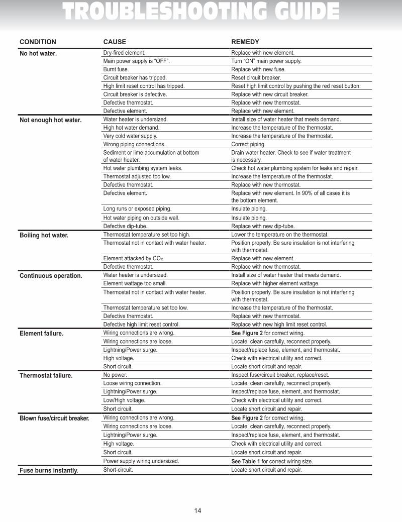
14
TROUBLESHOOTING GUIDECONDITION CAUSE REMEDY
No hot water. Dry-fired element. Replace with new element.Main power supply is “OFF”. Turn “ON” main power supply.Burnt fuse. Replace with new fuse.Circuit breaker has tripped. Reset circuit breaker.High limit reset control has tripped. Reset high limit control by pushing the red reset button.Circuit breaker is defective. Replace with new circuit breaker.Defective thermostat. Replace with new thermostat.Defective element. Replace with new element.
Not enough hot water. Water heater is undersized. Install size of water heater that meets demand.High hot water demand. Increase the temperature of the thermostat.Very cold water supply. Increase the temperature of the thermostat.Wrong piping connections. Correct piping.Sediment or lime accumulation at bottomof water heater.
Drain water heater. Check to see if water treatmentis necessary.
Hot water plumbing system leaks. Check hot water plumbing system for leaks and repair.Thermostat adjusted too low. Increase the temperature of the thermostat.Defective thermostat. Replace with new thermostat.Defective element. Replace with new element. In 90% of all cases it is
the bottom element.Long runs or exposed piping. Insulate piping.Hot water piping on outside wall. Insulate piping.Defective dip-tube. Replace with new dip-tube.
Boiling hot water. Thermostat temperature set too high. Lower the temperature on the thermostat.Thermostat not in contact with water heater. Position properly. Be sure insulation is not interfering
with thermostat.Element attacked by CO2. Replace with new element.Defective thermostat. Replace with new thermostat.
Continuous operation. Water heater is undersized. Install size of water heater that meets demand.Element wattage too small. Replace with higher element wattage.Thermostat not in contact with water heater. Position properly. Be sure insulation is not interfering
with thermostat.Thermostat temperature set too low. Increase the temperature of the thermostat.Defective thermostat. Replace with new thermostat.Defective high limit reset control. Replace with new high limit reset control.
Element failure. Wiring connections are wrong. See Figure 2 for correct wiring.Wiring connections are loose. Locate, clean carefully, reconnect properly.Lightning/Power surge. Inspect/replace fuse, element, and thermostat.High voltage. Check with electrical utility and correct.Short circuit. Locate short circuit and repair.
Thermostat failure. No power. Inspect fuse/circuit breaker, replace/reset.Loose wiring connection. Locate, clean carefully, reconnect properly.Lightning/Power surge. Inspect/replace fuse, element, and thermostat.Low/High voltage. Check with electrical utility and correct.Short circuit. Locate short circuit and repair.
Blown fuse/circuit breaker. Wiring connections are wrong. See Figure 2 for correct wiring.Wiring connections are loose. Locate, clean carefully, reconnect properly.Lightning/Power surge. Inspect/replace fuse, element, and thermostat.High voltage. Check with electrical utility and correct.Short circuit. Locate short circuit and repair.Power supply wiring undersized. See Table 1 for correct wiring size.
Fuse burns instantly. Short-circuit. Locate short circuit and repair.
Man Electrique-GI-IM017Bi-1211.indd 15 11-12-21 12:30 PM
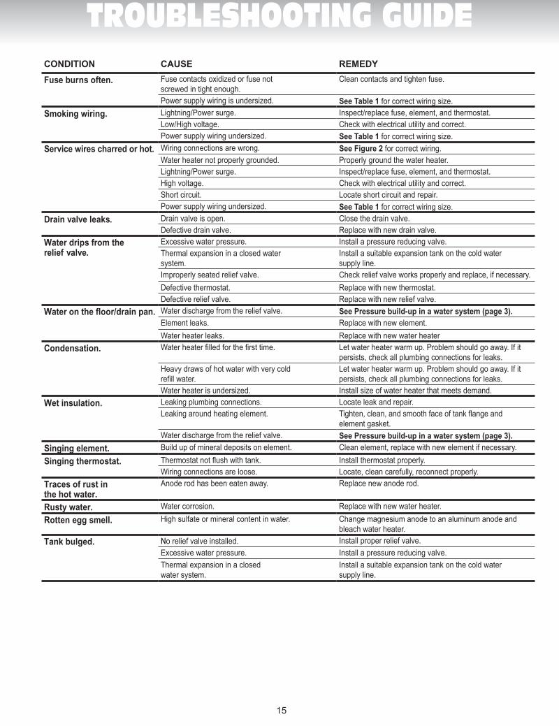
15
TROUBLESHOOTING GUIDECONDITION CAUSE REMEDY
Fuse burns often. Fuse contacts oxidized or fuse not screwed in tight enough.
Clean contacts and tighten fuse.
Power supply wiring is undersized. See Table 1 for correct wiring size.Smoking wiring. Lightning/Power surge. Inspect/replace fuse, element, and thermostat.
Low/High voltage. Check with electrical utility and correct.Power supply wiring undersized. See Table 1 for correct wiring size.
Service wires charred or hot. Wiring connections are wrong. See Figure 2 for correct wiring.Water heater not properly grounded. Properly ground the water heater.Lightning/Power surge. Inspect/replace fuse, element, and thermostat.High voltage. Check with electrical utility and correct.Short circuit. Locate short circuit and repair.Power supply wiring undersized. See Table 1 for correct wiring size.
Drain valve leaks. Drain valve is open. Close the drain valve.Defective drain valve. Replace with new drain valve.
Water drips from therelief valve.
Excessive water pressure. Install a pressure reducing valve.Thermal expansion in a closed watersystem.
Install a suitable expansion tank on the cold water supply line.
Improperly seated relief valve. Check relief valve works properly and replace, if necessary.Defective thermostat. Replace with new thermostat.Defective relief valve. Replace with new relief valve.
Water on the floor/drain pan. Water discharge from the relief valve. See Pressure build-up in a water system (page 3).Element leaks. Replace with new element.Water heater leaks. Replace with new water heater
Condensation. Water heater filled for the first time. Let water heater warm up. Problem should go away. If it persists, check all plumbing connections for leaks.
Heavy draws of hot water with very cold refill water.
Let water heater warm up. Problem should go away. If itpersists, check all plumbing connections for leaks.
Water heater is undersized. Install size of water heater that meets demand.Wet insulation. Leaking plumbing connections. Locate leak and repair.
Leaking around heating element. Tighten, clean, and smooth face of tank flange andelement gasket.
Water discharge from the relief valve. See Pressure build-up in a water system (page 3).
Singing element. Build up of mineral deposits on element. Clean element, replace with new element if necessary.
Singing thermostat. Thermostat not flush with tank. Install thermostat properly.Wiring connections are loose. Locate, clean carefully, reconnect properly.
Traces of rust in the hot water.
Anode rod has been eaten away. Replace new anode rod.
Rusty water. Water corrosion. Replace with new water heater.
Rotten egg smell. High sulfate or mineral content in water. Change magnesium anode to an aluminum anode and bleach water heater.
Tank bulged. No relief valve installed. Install proper relief valve.Excessive water pressure. Install a pressure reducing valve.Thermal expansion in a closed water system.
Install a suitable expansion tank on the cold watersupply line.
Man Electrique-GI-IM017Bi-1211.indd 16 11-12-21 12:30 PM
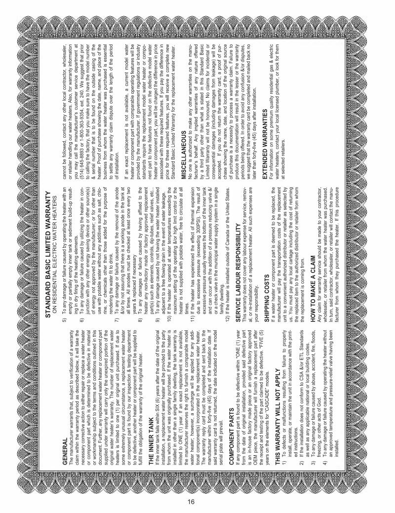
16
ST
AN
DA
RD
BA
SIC
LIM
ITE
D W
AR
RA
NT
YO
N R
ES
IDE
NTI
AL
ELE
CTR
IC W
ATE
R H
EA
TER
S
GE
NE
RA
LTh
e m
anuf
actu
rer w
arra
nts
that
, sub
ject
to v
erifi
catio
n of
a w
arra
nty
clai
m w
ithin
the
war
rant
y pe
riod
as d
escr
ibed
bel
ow, i
t will
take
the
nece
ssar
y co
rrect
ive
actio
n to
eith
er re
pair
or re
plac
e a
wat
er h
eate
r or
com
pone
nt p
art w
hich
is d
eter
min
ed to
be
defe
ctiv
e in
mat
eria
l or
wor
kman
ship
sub
ject
to th
e te
rms
and
cond
ition
s ou
tline
d in
this
do
cum
ent.
Furth
er, a
ny re
plac
emen
t wat
er h
eate
r or c
ompo
nent
par
t su
pplie
d un
der w
arra
nty
will
carry
onl
y th
e un
expi
red
porti
on o
f the
or
igin
al w
ater
hea
ter’s
war
rant
y. T
he n
umbe
r of r
epla
cem
ent w
ater
he
ater
s is
lim
ited
to o
ne (
1) p
er o
rigin
al u
nit p
urch
ased
. If d
ue to
so
me
extre
mel
y un
usua
l circ
umst
ance
, a re
plac
emen
t wat
er h
eate
r or
com
pone
nt p
art i
s fo
und
by o
ur in
spec
tion
& te
stin
g de
partm
ent
to b
e de
fect
ive,
ano
ther
hea
ter o
r com
pone
nt p
art w
ill be
sup
plie
d to
fu
lfill
the
oblig
atio
n of
the
war
rant
y of
the
orig
inal
hea
ter.
THE
INN
ER
TA
NK
If th
e in
ner t
ank
fails
with
in S
IX (6
) yea
rs a
fter t
he d
ate
of th
e or
igin
al
inst
alla
tion,
a re
plac
emen
t wat
er h
eate
r will
be p
rovi
ded
to th
e pa
rty
from
who
m th
e un
it w
as o
rigin
ally
pur
chas
ed. I
f the
wat
er h
eate
r is
inst
alle
d in
oth
er th
an a
sin
gle
fam
ily d
wel
ling,
the
tank
war
rant
y is
lim
ited
to O
NE
(1)
year
. If a
n ex
act r
epla
cem
ent i
s no
t ava
ilabl
e,
the
man
ufac
ture
r res
erve
s th
e rig
ht to
furn
ish
a co
mpa
rabl
e m
odel
w
ater
hea
ter;
how
ever
, a
surc
harg
e w
ill be
app
lied
for
any
addi
-tio
nal c
ompo
nent
(s)
inco
rpor
ated
in th
e re
plac
emen
t wat
er h
eate
r. Th
e w
arra
nty
repl
y ca
rd m
ust b
e co
mpl
eted
and
sen
t bac
k to
the
man
ufac
ture
r w
ithin
for
ty-fi
ve (
45)
days
of
the
inst
alla
tion
date
. If
said
war
rant
y ca
rd is
not
retu
rned
, the
dat
e in
dica
ted
on th
e m
odel
se
rial p
late
will
prev
ail.
CO
MP
ON
EN
T P
AR
TSIf
any
com
pone
nt p
art i
s fo
und
to b
e de
fect
ive
with
in *O
NE
(1) y
ear
from
the
dat
e of
orig
inal
inst
alla
tion,
pro
vide
d sa
id d
efec
tive
part
is a
n in
-hou
se fa
ctor
y m
ade
piec
e or
an
orig
inal
fact
ory
appr
oved
O
EM p
iece
, the
man
ufac
ture
r w
ill fu
rnis
h a
repl
acem
ent p
art a
fter
the
rece
ipt a
nd te
stin
g of
the
part
clai
med
to b
e de
fect
ive.
*FIV
E (5
) ye
ars
on th
e el
emen
ts fo
r “C
ASC
ADE”
mod
els.
THIS
WA
RR
AN
TY W
ILL
NO
T A
PP
LY1)
To
def
ects
or
mal
func
tions
res
ultin
g fro
m f
ailu
re t
o pr
oper
ly
inst
all,
oper
ate,
or m
aint
ain
the
unit
in a
ccor
danc
e w
ith th
e pr
int-
ed in
stru
ctio
ns.
2)
If th
e in
stal
latio
n do
es n
ot c
onfo
rm to
CSA
&/o
r ETL
Sta
ndar
ds
as w
ell a
s an
y ap
plic
able
nat
iona
l or l
ocal
bui
ldin
g co
des.
3)
To a
ny d
amag
e or
failu
re c
ause
d by
abu
se, a
ccid
ent,
fire,
floo
ds,
freez
ing,
or o
ther
act
s of
God
.4)
To
any
dam
age
or fa
ilure
cau
sed
by o
pera
ting
the
heat
er w
ithou
t an
app
rove
d te
mpe
ratu
re a
nd p
ress
ure-
relie
f val
ve h
avin
g be
en
inst
alle
d.
5)
To a
ny d
amag
e or
failu
re c
ause
d by
ope
ratin
g th
e he
ater
with
an
empt
y or
par
tially
em
pty
inne
r tan
k or
sed
imen
t bui
ld-u
p re
sult-
ing
in d
ry fi
ring
of th
e he
atin
g el
emen
ts.
6)
To a
ny d
amag
e or
failu
re c
ause
d by
util
izin
g th
e he
ater
in c
on-
junc
tion
with
any
oth
er e
nerg
y sa
ving
dev
ice
or o
ther
sou
rce(
s)
of e
nerg
y no
t app
rove
d by
the
man
ufac
ture
r; or
for
othe
r th
an
use
with
pot
able
wat
er w
ithou
t any
add
itive
s su
ch a
s sa
lt, c
hlo-
rine,
or
chem
ical
s ot
her
than
tho
se a
dded
for
the
pur
pose
of
rend
erin
g th
e w
ater
fit t
o dr
ink.
7)
To a
ny d
amag
e or
failu
re c
ause
d by
the
rem
oval
of t
he a
node
&/
or b
y no
t ass
urin
g th
at th
ere
is a
wor
king
ano
de in
the
tank
at
all t
imes
. All
anod
es m
ust b
e ch
ecke
d at
leas
t onc
e ev
ery
two
year
s &
repl
aced
if n
eces
sary
8)
To a
ny d
amag
es o
r fa
ilure
cau
sed
by h
avin
g af
fixed
to
the
heat
er a
ny n
on-fa
ctor
y m
ade
or fa
ctor
y ap
prov
ed r
epla
cem
ent
part(
s) s
uch
as e
lem
ents
, con
trols
, dip
-tube
s, re
lief v
alve
s, e
tc...
9)
To a
ny d
amag
e ca
used
by
not h
avin
g th
e w
ater
hea
ter i
nsta
lled
adja
cent
to a
free
flow
ing
drai
n in
the
even
t of w
ater
leak
age.
10
) If t
he h
eate
r is
ope
rate
d at
wat
er te
mpe
ratu
res
exce
edin
g th
e m
axim
um s
ettin
g of
the
oper
atin
g &/
or h
igh
limit
cont
rol o
r the
he
ater
is n
ot s
uppl
ied
with
pot
able
wat
er, f
ree
to c
ircul
ate
at a
ll tim
es.
11) I
f the
hea
ter
has
expe
rienc
ed th
e ef
fect
of t
herm
al e
xpan
sion
du
e to
exc
essi
ve p
ress
ure
(exc
eedi
ng 3
00PS
I). T
he r
esul
t of
ex
cess
ive
pres
sure
usu
ally
reve
rses
the
botto
m o
f the
inne
r tan
k an
d ca
n oc
cur w
ith th
e ad
ditio
n of
a p
ress
ure
redu
cing
val
ve &
/or
a c
heck
val
ve in
the
mun
icip
al w
ater
sup
ply
syst
em in
a s
ingl
e fa
mily
dw
ellin
g.12
) If t
he h
eate
r is
inst
alle
d ou
tsid
e of
Can
ada
or th
e U
nite
d St
ates
.
SE
RV
ICE
LA
BO
UR
RE
SP
ON
SIB
ILIT
YTh
is w
arra
nty
does
not
cov
er a
ny la
bour
exp
ense
for s
ervi
ce, r
emov
-al
, or r
e-in
stal
latio
n of
a re
plac
emen
t hea
ter.
All s
uch
expe
nses
are
yo
ur re
spon
sibi
lity.
SH
IPP
ING
CO
STS
If a
wat
er h
eate
r or c
ompo
nent
par
t is
deem
ed to
be
repl
aced
, the
m
anuf
actu
rer
will
pay
the
trans
porta
tion
cost
s of
the
rep
lace
men
t un
it to
a c
onve
nien
t aut
horiz
ed d
istri
buto
r or r
etai
ler a
s se
lect
ed b
y us
. You
mus
t pay
any
loca
l car
tage
incl
udin
g th
e co
st o
f ret
urni
ng
the
repl
aced
item
to th
e au
thor
ized
dis
tribu
tor o
r ret
aile
r fro
m w
hom
th
e re
plac
emen
t is
com
ing
from
.
HO
W T
O M
AK
E A
CLA
IMAn
y cl
aim
for w
arra
nty
serv
ice
shou
ld b
e m
ade
to y
our c
ontra
ctor
, w
hole
sale
r, or
reta
iler f
rom
who
m th
e w
ater
hea
ter w
as p
urch
ased
. In
turn
, sai
d co
ntra
ctor
, who
lesa
ler,
or re
taile
r will
cont
act t
he m
anu-
fact
urer
fro
m w
hom
the
y pu
rcha
sed
the
heat
er.
If th
is p
roce
dure
cann
ot b
e fo
llow
ed, c
onta
ct a
ny o
ther
loca
l con
tract
or, w
hole
sale
r, or
reta
iler h
andl
ing
our w
ater
hea
ters
. Als
o, fo
r war
rant
y in
form
atio
n yo
u m
ay c
all t
he m
anuf
actu
rer’s
cus
tom
er s
ervi
ce d
epar
tmen
t at
(5
14) 6
45-8
893
or 1
-800
-363
-935
4, e
xt. 2
40. W
e su
gges
t tha
t prio
r to
cal
ling
the
fact
ory,
that
you
mak
e su
re to
hav
e th
e m
odel
num
ber
& se
rial n
umbe
r th
at is
to
be f
ound
on
the
outs
ide
casi
ng o
f th
e he
ater
. Pro
of o
f pur
chas
e sh
owin
g th
e da
te, n
ame,
and
pla
ce o
f the
bu
sine
ss fr
om w
hom
the
wat
er h
eate
r w
as p
urch
ased
is e
ssen
tial
to s
ettle
any
war
rant
y cl
aim
dis
pute
ove
r th
e le
ngth
of t
he p
erio
d of
inst
alla
tion.
If an
exa
ct r
epla
cem
ent
is n
ot a
vaila
ble,
a c
urre
nt m
odel
wat
er
heat
er o
r com
pone
nt p
art w
ith c
ompa
rabl
e op
erat
ing
feat
ures
will
be
prov
ided
by
the
man
ufac
ture
r. If
gove
rnm
ent r
egul
atio
ns o
r ind
ustry
st
anda
rds
requ
ire th
e re
plac
emen
t mod
el w
ater
hea
ter
or c
ompo
-ne
nt p
art t
o ha
ve fe
atur
es n
ot fo
und
on th
e de
fect
ive
mod
el w
ater
he
ater
or c
ompo
nent
par
t, yo
u w
ill be
cha
rged
the
diffe
renc
e in
pric
e as
soci
ated
with
thes
e re
quire
d fe
atur
es. I
f you
pay
the
diffe
renc
e in
pr
ice
for
thes
e re
quire
d fe
atur
es, y
ou w
ill re
ceiv
e a
com
plet
e ne
w
Stan
dard
Bas
ic L
imite
d W
arra
nty
for t
he re
plac
emen
t wat
er h
eate
r.
MIS
CE
LLA
NE
OU
SN
o on
e is
aut
horiz
ed to
mak
e an
y ot
her
war
rant
ies
on th
e m
anu-
fact
urer
’s b
ehal
f. An
y im
plie
d w
arra
ntie
s of
any
nat
ure
offe
red
by a
thi
rd p
arty
oth
er t
han
wha
t is
sta
ted
in t
his
Stan
dard
Bas
ic
Lim
ited
War
rant
y w
ill no
t be
hono
ured
. No
clai
ms
for
inci
dent
al o
r co
nseq
uent
ial d
amag
es (
incl
udin
g da
mag
es fr
om le
akag
e) w
ill be
ac
cept
ed.
If yo
u do
not
ret
urn
the
war
rant
y ca
rd, a
pro
of o
f pur
-ch
ase
show
ing
the
nam
e, d
ate,
and
loca
tion
of th
e or
igin
al s
ourc
e of
pur
chas
e is
a n
eces
sity
to p
roce
ss a
war
rant
y cl
aim
. Fai
lure
to
prod
uce
this
doc
umen
tatio
n w
ill re
sult
in th
e le
sser
or t
he w
arra
nty
perio
ds b
eing
offe
red.
In o
rder
to a
void
any
con
fusi
on &
/or d
ispu
tes,
w
e su
gges
t tha
t the
war
rant
y ca
rd b
e co
mpl
eted
and
mai
led
back
no
late
r tha
n fo
rty-fi
ve (4
5) d
ays
afte
r ins
talla
tion.
EX
TEN
DE
D W
AR
RA
NTI
ES
For i
nfor
mat
ion
on s
ome
prem
ium
qua
lity
resi
dent
ial g
as &
ele
ctric
w
ater
hea
ters
, con
tact
you
r loc
al li
cens
ed p
lum
ber,
or lo
ok fo
r the
m
at s
elec
ted
reta
ilers
.
Man Electrique-GI-IM017Bi-1211.indd 17 11-12-21 12:30 PM