Embed Size (px)
Citation preview
Residential Fall Protection
Presented By: Consultation Education & Training (CET) Division
Michigan Occupational Safety & Health Administration Michigan Department of Licensing and Regulatory Affairs
www.michigan.gov/miosha(517) 284-7720
SP #35 (Revised 09/15)
Table of Contents
PowerPoint Presentation .......................................................................................4
Fall Protection Standard - Part 45........................................................................33
Enforcement Policy..............................................................................................75
Sample Fall Protection Plan & Templates.......................................................... 81
MIOSHA Fact Sheets .........................................................................................102

PowerPoint Presentation

Fall Protection in Residential Construction
Consultation Education &Training (CET) Division Michigan Occupational Safety & Health Administration
Michigan Department of Licensing and Regulatory Affairs www.michigan.gov/miosha
(517) 284-7720
Course OverviewModule 1 will provide you with an overview of:
the interim policy and the old definition of“residential construction”the revised policy and the new definition of“residential construction”And will cover the reasons for the changes to thepolicy
Module 2 will provide you with an overview of:the conventional fall protection systemsthe alternative methods for fall protection asdefined in 1926.501(b)(13)and a look at alternative work methods that maybe used to reduce or eliminate the exposure tofall hazards
Course Overview
4

Module 3 will provide you with an overview of:when it is appropriate to implement and use aFall Protection PlanMIOSHA’s stance on feasibilitythe key components of a Fall Protection Planthe job hazard analysis (JHA)the definitions of a Qualified Person and aCompetent Person
Course Overview
Attention:Employers must know that the:examples of fall protection shown in the
photographs contained in this presentation do not represent all possible work methods that can be used in residential construction.examples of fall protection in the photographs in
this presentation may not be suitable in all situationsemployer is responsible for ensuring compliance
with all applicable MIOSHA requirements
Module 1:Residential Fall Protection Program Update
5
Objectives
This Module will provide you with an overview of:the reasons for the change to the interim policythe interim policy and the old definition of“residential construction”the revised policy and the new definition of“residential construction”
Reasons for changeThere continues to be high numbers of fall-related fatalities in residential construction
Many different fall protection options areavailable for residential construction activities
There were several recommendations to rescindthe interim directive
The residential fall protection requirements havealways been established in Part 45:1926.501(b)(13). The revised policy implementsthat standard as originally intended.
Recommendations to rescind the directive came from:
Advisory Committee on ConstructionSafety and Health - OSHA
Occupational Safety and Health State PlanAssociation
National Association of Homebuilders
6

COM 04-1 Interim Policyresidential fall protection compliance criteria issued in 2004
permitted employers engaged in certain residential construction activities to use alternative procedures instead of conventional fall protection without demonstrating infeasibility or greater hazard and without a written site specific plan
was an interim policy and was never intended to be permanent
COM 04-1 Interim PolicyDefined residential construction as:
Structures where the working environment and the construction materials, methods, and procedures employed were essentially the same as those used for typical house (single-family dwelling) and townhouse construction.
COM 04-1 Interim Policy
Also stated that discrete parts of a large commercial structure could come within the scope of the directive (for example, a shingled entranceway to a mall), but that did not mean that the entire structure thereby came within the terms of the directive
7
So what changed?On March 28th, 2011 MIOSHA issued COM 04-1R1which:
rescinded COM 04-1 issued on June 24th, 2004requires employers engaged in residentialconstruction to comply with rule 1926.501(b)(13)as it was intendedintroduced a new definition of residentialconstruction
MIOSHA Part 45. Fall ProtectionRule 1926.501(b)(13): Residential Construction
Each employee engaged in residentialconstruction activities 6 feet (1.8 m) or more above lower levels shall be protected by guardrail systems, safety net systems, or personal fall arrest system unless another provision in paragraph (b) of this section provides for an alternative fall protection measure.
MIOSHA Part 45. Fall Protection
Rule 1926.501(b)(13): Residential ConstructionException: When the employer can demonstratethat it is infeasible or creates a greater hazard to use these systems, the employer shall develop and implement a fall protection plan which meets the requirements of paragraph (k) of 1926.502.
8
Residential ConstructionRe-defined:COM 04-1R1 defines residential construction as
meeting these two requirements:1) the end-use of the structure is required to be a
home or dwelling2) and the building in question must be
constructed using traditional wood frame construction materials and methods
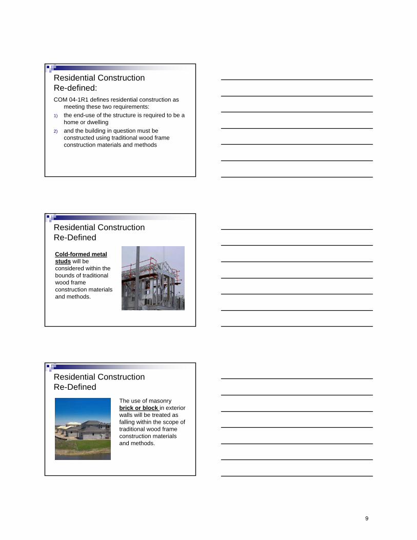
Residential Construction Re-Defined
Cold-formed metal studs will be considered within the bounds of traditional wood frame construction materials and methods.
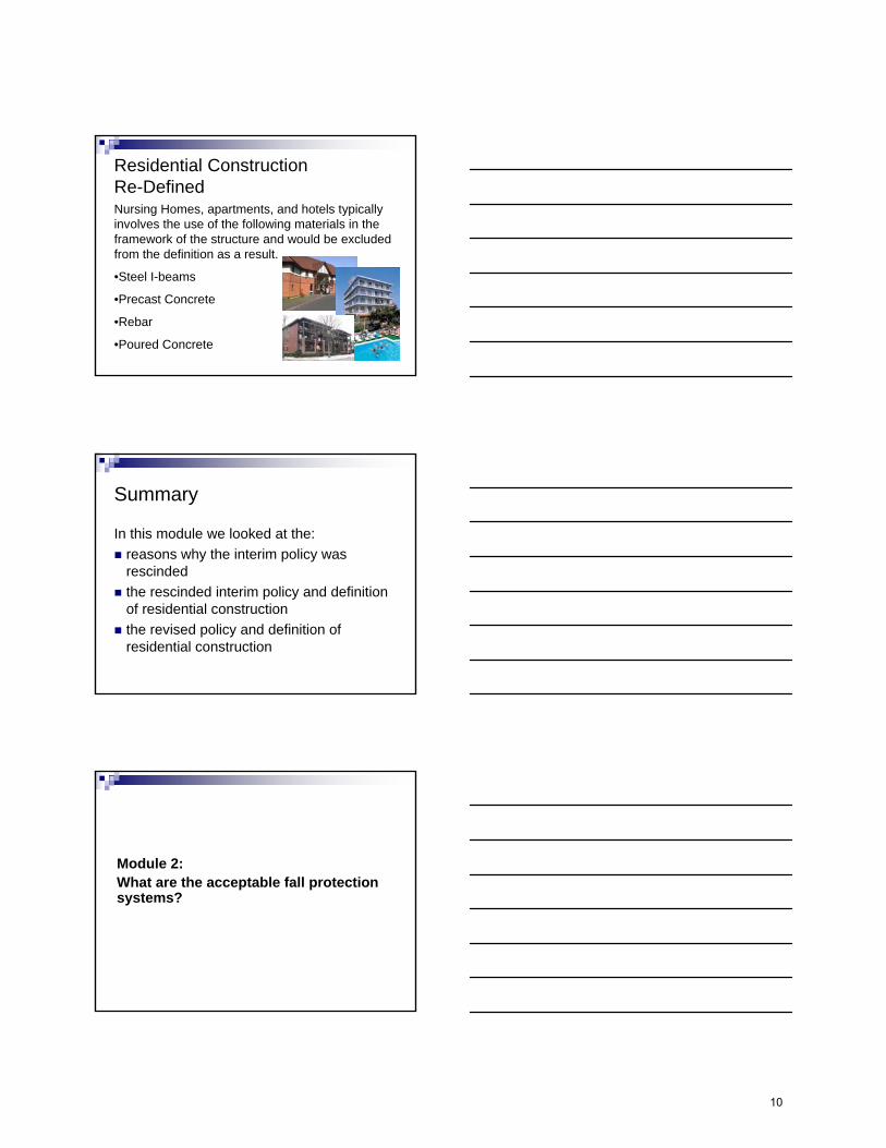
Residential Construction Re-Defined
The use of masonry brick or block in exterior walls will be treated as falling within the scope of traditional wood frame construction materials and methods.
9
Nursing Homes, apartments, and hotels typically involves the use of the following materials in the framework of the structure and would be excluded from the definition as a result.
•Steel I-beams
•Precast Concrete
•Rebar
•Poured Concrete
Residential Construction Re-Defined
Summary
In this module we looked at the:reasons why the interim policy wasrescindedthe rescinded interim policy and definitionof residential constructionthe revised policy and definition ofresidential construction
Module 2:What are the acceptable fall protection systems?
10
Module 2 will provide you with an overview of:the conventional fall protection systemsthe alternative methods for fall protection asdefined in 1926.501(b)(13)and a look at alternative work methods that maybe used to reduce or eliminate the exposure tofall hazards
Objectives
Acceptable fall protection systems
Guardrail systems
Safety net systems
Personal fall arrest systems
Fall restraint / work positioning systems
Hole Covers
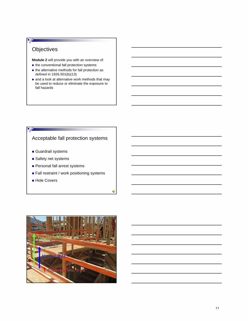
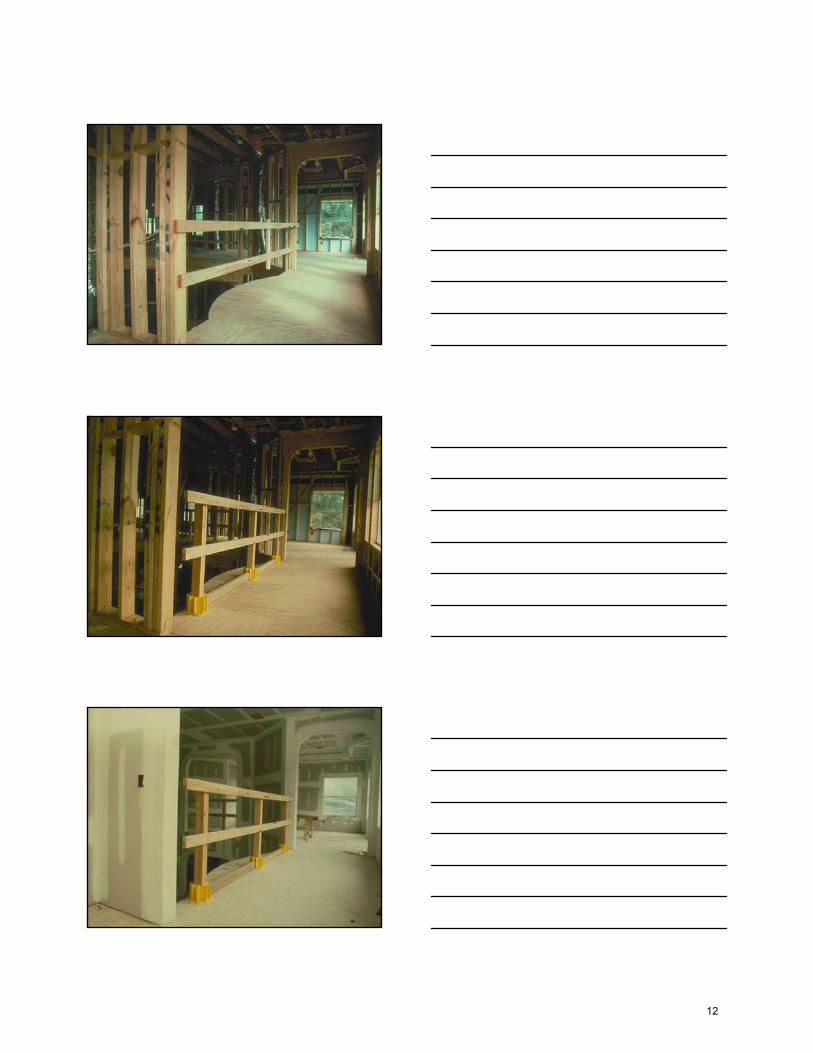
Top-rail @ 42”TopTop--rail @ 42rail @ 42””
Mid-rail @ 21”MidMid--rail @ 21rail @ 21””
Toeboard min. 3-1/2”ToeboardToeboard min. 3min. 3--1/21/2””
11
12
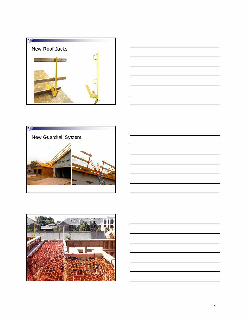
New Roof Jacks
New Guardrail System
13

Personal Fall Arrest System (PFAS) ComponentsPersonal Fall Arrest System (PFAS) Components
Anchorage Point
Lifeline
Connector
ShockAbsorber
BodyHarness
Anchor points
14

Anchor point: inside and out
Swing Fall HazardSwing Fall Hazard
15
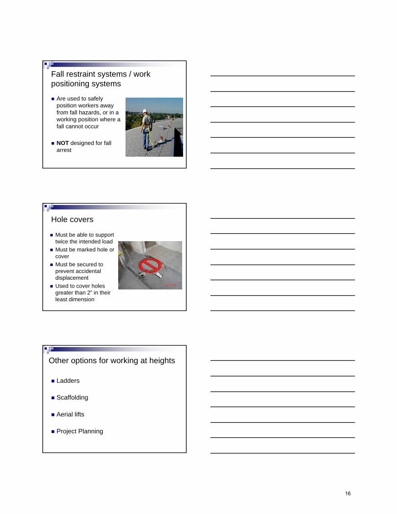
Fall restraint systems / work positioning systems
Are used to safelyposition workers awayfrom fall hazards, or in aworking position where afall cannot occur
NOT designed for fallarrest
Hole covers
Must be able to supporttwice the intended loadMust be marked hole orcoverMust be secured toprevent accidentaldisplacementUsed to cover holesgreater than 2” in theirleast dimension
Other options for working at heights
Ladders
Scaffolding
Aerial lifts
Project Planning
16
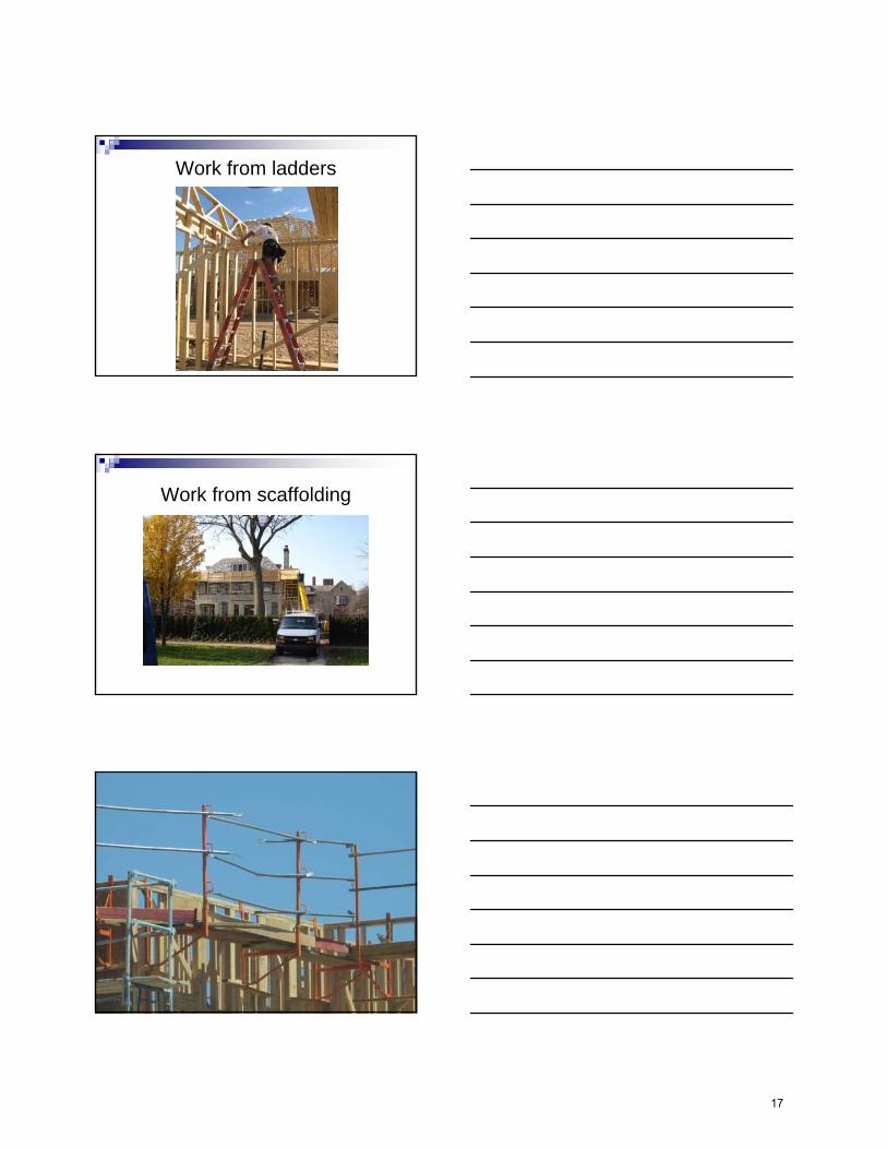
Work from ladders
Work from scaffolding
17
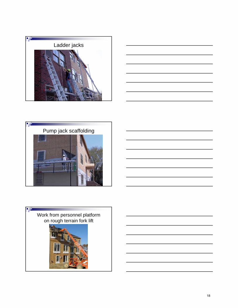
Ladder jacks
Pump jack scaffolding
Work from personnel platform on rough terrain fork lift
18

How will this affect your work?
Any work 6 feet or more above lower levels willrequire some type of fall protectionExamples:
Foundation form workInstalling floor trusses and sheathingBuilding second floor wallsWall openings, stairs and holesInstalling roof trusses and sheathingRoofing (tear-off and installing new shingles)
Foundation Form Work
19
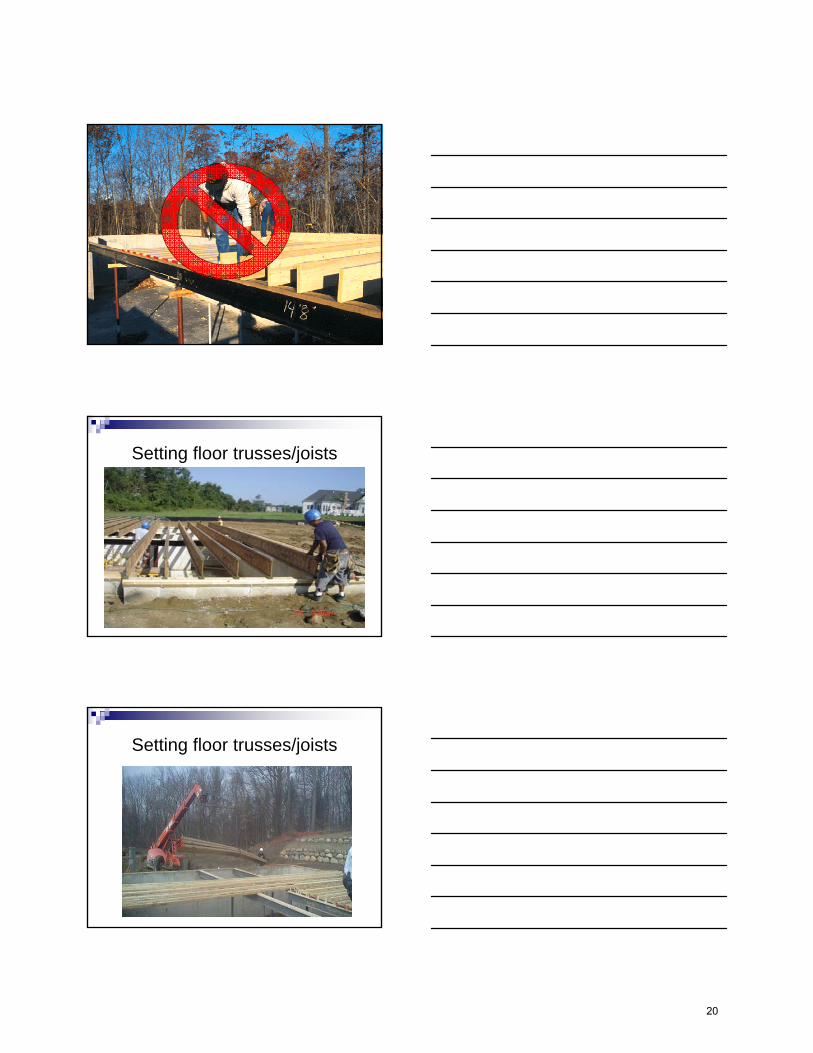
Setting floor trusses/joists
Setting floor trusses/joists
20
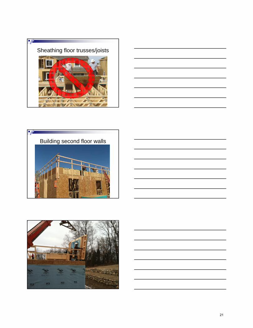
Sheathing floor trusses/joists
Building second floor walls
21
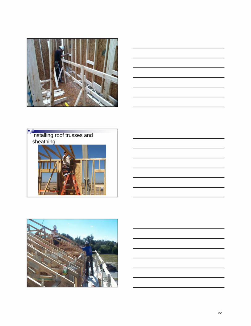
Installing roof trusses and sheathing
22
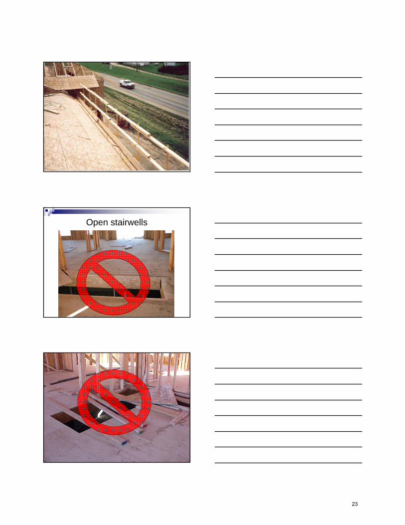
Open stairwells
23
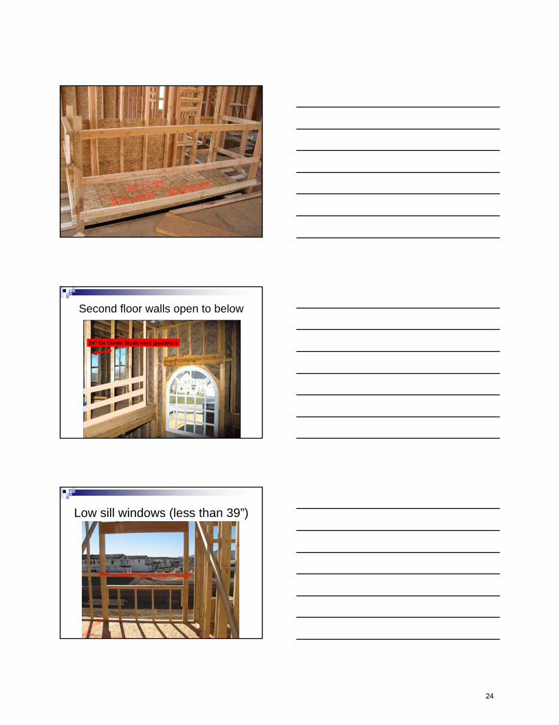
Second floor walls open to below
24” On Center Studs need guardrails
Low sill windows (less than 39”)
24
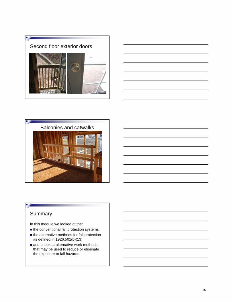
Second floor exterior doors
Balconies and catwalks
Summary
In this module we looked at the:the conventional fall protection systemsthe alternative methods for fall protectionas defined in 1926.501(b)(13)and a look at alternative work methodsthat may be used to reduce or eliminatethe exposure to fall hazards
25
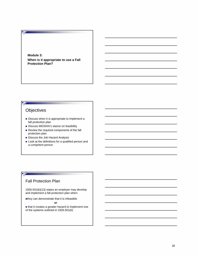
Module 3:When is it appropriate to use a Fall Protection Plan?
Objectives
Discuss when it is appropriate to implement afall protection planDiscuss MIOSHA’s stance on feasibilityReview the required components of the fallprotection planDiscuss the Job Hazard AnalysisLook at the definitions for a qualified person anda competent person
Fall Protection Plan
1926.501(b)(13) states an employer may develop and implement a fall protection plan when:
they can demonstrate that it is infeasibleor
that it creates a greater hazard to implement oneof the systems outlined in 1926.501(b)
26
MIOSHA’s Stance
It is presumed that it is feasible and will notcreate a greater hazard to implement at leastone of the fall protection measures outlined in1926.501(b)
The employer has the burden of establishingthat it is appropriate to implement a fallprotection plan that is compliant with1926.502(k) for a particular workplace situation
Establishing infeasibility or greater hazard
Do your homeworkConduct a Job Hazard AnalysisExplore all optionsSpeak with industry expertsConsult with MIOSHA
Last resortDevelop and implement a written and sitespecific fall protection plan meeting the requirements of 1926.502(k)
Fall Protection Plan
Written document
Developed by a qualified person
Site specific
Implemented by a competent person
Kept up-to-date and available on-site
Employees trained on the specific plan
27
Fall Protection PlanA written document prepared by a qualifiedperson and developed specifically for the sitewhere the residential construction work isbeing performedChanges to the plan must be approved by thequalified personA copy of the plan with all approved changesshall be maintained at the job site.
Developed by a Qualified Person
Qualified Person:A person who by possession of a recognized
degree or certificate of professional standingor
who, by extensive knowledge, training, andexperience, has successfully demonstrated the ability to solve or resolve problems relating to the subject matter and work
Fall Protection Plan
Site specificA Job Hazard Analysis may be used to meetthe site specific requirement when done for each siteA written plan developed for the repetitive use for a particular style/model home would be considered site-specific with respect to a particular site only if it fully addresses all issues related to fall protection at that site.
28
What is a Job Hazard Analysis?
It is a template that is customized to the job to identify:
The overall jobSpecific tasks or stepsPotential hazards for each task or stepControls and means for protectionSign-off by the workers
Fall protection plan
Written plan must includeReasons why fall protection or alternate workmethods are infeasible or pose a greater hazardAlternative measures used to reduce or eliminate fall hazardsSpecific locations where these alternative measures will be implemented
Locations where conventional fall protection cannot be used shall be designated as Controlled Access Zones in compliance with 1926.502(g)Employees designated to work in a CAZ must be identified in the plan
Fall protection plan
29
The implementation of the fall protection planshall be under the supervision of a competent person
Competent Person:A person who is experienced and capable of identifying an existing or potential hazard in surroundings, or under working conditions
andhas the authority and knowledge to take prompt corrective measures to eliminate hazards
Fall protection plan
Fall protection plans cannot be used for:
Guarding of floor holes and openings 6 feet ormore above the lower levelGuarding of wall openings (greater than 18”opening) & window sills (less than 39”) 6 feet or more above the lower levelGuarding of floors, mezzanines, balconies, andwalkways with an unprotected side or edge 6 feet or more above the lower levelGuarding of excavations 6 feet or more in depthwhen not readily seen
Summary
In this module we:Discussed when it is appropriate to implement afall protection planDiscussed MIOSHA’s stance on feasibilityReviewed the required components of the fallprotection planDiscussed the job hazard analysis (JHA)Looked at the definitions for a qualified personand a competent person
30

Questions????
For more frequent updates:
“Like” us on Facebook at:
www.facebook.com/MichiganOSHA
“Follow” us on Twitter at:
www.twitter.com/MI_OSHA
Michigan Occupational Safety & Health Administration Consultation Education & Training Division
530 W. Allegan St., P.O. Box 30643Lansing, Michigan 48909-8143
For further information or to request consultation, education and training services, call (517) 284-7720
orvisit our website at www.michigan.gov/miosha
Thank you For Thank you For Attending This PresentationAttending This Presentation
31
Fall Protection Standard Part 45
1
MIOSHA-STD-1326 (05/15)42 Pages
For further informationPh: 517-322-1845
www.michigan.gov/mioshastandards
DEPARTMENT OF LICENSING AND REGULATORY AFFAIRS
DIRECTOR’S OFFICE
CONSTRUCTION SAFETY STANDARDS
Filed with the Secretary of State on September 3, 1996 (as amended April 6, 2015)
These rules become effective immediately upon filing with the Secretary of Stateunless adopted under section 33, 44, or 45a(6) of 1969 PA 306.
Rules adopted under these sections become effective 7 days after filing with the Secretary of State.
(By authority conferred on the director of the department of licensing and regulatory affairsby sections 19 and 21 of 1974 PA 154, MCL 408.1019 and 408.1021,
and Executive Reorganization Order Nos. 1996-2, 2003-1, 2008-4,and 2011-4, MCL 445.2001, 445.2011, 445.2025, and 445.2030)
R 408.44501 and R 408.44502 of the Michigan Administrative Code are amended, as follows:
PART 45. FALL PROTECTION
Table of Contents:R 408.44501 Scope ..................................................... 1R 408.44502 Adopted and referenced standards. ....... 2
OSHA FALL PROTECTION1926.500 Scope, Application, and Definitions
Applicable to this Subpart ...................................... 41926.501 Duty to have Fall Protection ......................... 71926.502 Fall Protection Systems Criteria and
Practices 91926.503 Training Requirements ............................... 16
Appendix A - Determining Roof Widths ...................... 17Appendix B - Guardrail Systems ................................ 22Appendix C - Personal Fall Arrest Systems ............... 23Appendix D - Positioning Device Systems.................. 28Appendix E - Sample Fall Protection Plan .................. 29
R 408.44501 Scope
Rule 4501. (1) The rules in this part set forth theminimum requirements and criteria for fall protection inconstruction workplaces, their applications, anddefinitions that are applicable to these rules.
(2) These rules do not apply where an employee ismaking an inspection, an investigation, or an assessmentof workplace conditions before the actual start ofconstruction work or after all construction work has beencompleted.
(3) The following provisions of the occupationalsafety and health administration (OSHA) regulations,except as amended in these rules, are adopted byreference in these rules:
(a) 29 C.F.R. § 1926.500 “Scope, Application, and definitions applicable to this subpart.”
(b) 29 C.F.R. § 1926.501 “Duty to have fall protection.”
(c) 29 C.F.R. § 1926.502 “Fall protection systems criteria and practices.”
(d) 29 C.F.R. § 1926.503 “Training requirements.”
(4) All of the following provisions are amendmentsto the OSHA regulations adopted by reference in theserules and are referenced in R 408.44502:
(a) Additional performance requirements forpersonal climbing equipment, lineman's body belts, safetystraps, and lanyards are contained in Construction SafetyStandard Part 16. “Power Transmission and Distribution.”
(b) The specifications for fall protectionrequirements for an employee working on certain types ofderricks are contained in Construction Safety StandardPart 10. “Lifting and Digging Equipment,” and Construction Safety Standard Part 32. “Aerial Work Platforms.”
(c) The specifications for fall protectionrequirements for an employee working on ladders andthe performance requirements for stairways, stair railsystems, and handrails are contained in ConstructionSafety Standard Part 11. “Fixed and Portable Ladders” and Construction Safety Standard Part 21 “Guarding of Walking and Working Areas.”
33
2
(d) The specifications for fall protection requirements for an employee working on a scaffold; performance requirements for a guardrail system; or for the performance requirements for falling object protection used on scaffolds are contained in Construction Safety Standard Part 12. “Scaffolds and Scaffold Platforms.”
(e) The specifications for fall protection requirements for an employee working on or in certain types of equipment used in tunneling operations are contained in Construction Safety Standard Part 14. “Tunnels, Shafts, Caissons, and Cofferdams.”
(f) The specifications for fall protection requirements for an employee working from aerial lifts, on poles, towers, or similar structures while engaged in the construction of electric transmission or distribution lines or equipment are contained in Construction Safety Standard Part 32. “Aerial Work Platforms.”
(g) The specifications for fall protection requirements for an employee performing steel erection work on buildings are contained in Construction Safety Standard Part 26. “Steel Erection.”
R 408.44502 Adopted and referenced standards.
Rule 4502. (1) The following federal occupational safety and health administration (OSHA) regulations are adopted by reference in these rules:
(a) 29 C.F.R. § 1926.500 “Scope, Application, and definitions applicable to this subpart,” effective July 10, 2014.
(b) 29 C.F.R. § 1926.501 “Duty to have fall protection,” effective January 26, 1995.
(c) 29 C.F.R. § 1926.502 “Fall protection systems criteria and practices,” effective January 26, 1995.
(d) 29 C.F.R. § 1926.503 “Training requirements,” effective January 26, 1995.
(2) The standards adopted in subrule (1) of this rule are available from the United States Department of Labor, Occupational Safety and Health Administration website: www.osha.gov, at no charge as of the time of adoption of these rules.
(3) The standards adopted in these rules are available for inspection at the Department of Licensing and Regulatory Affairs, MIOSHA Regulatory Services Section, 7150 Harris Drive, Lansing, Michigan, 48909-8143.
(4) The standards adopted in these rules may be obtained from the publisher or may be obtained from the Department of Licensing and Regulatory Affairs, MIOSHA Regulatory Services Section, 7150 Harris Drive, P.O. Box 30643, Lansing, Michigan, 48909-8143, plus $20.00 for shipping and handling.
(5) The following Michigan occupational safety and health (MIOSHA) standards are referenced in these rules. Up to 5 copies of these standards may be obtained at no charge from the Michigan Department of Licensing and Regulatory Affairs, MIOSHA Regulatory Services Section, 7150 Harris Drive, P.O. Box 30643, Lansing, Michigan, 48909-8143 or via the internet at website: www.michigan.gov/mioshastandards. For quantities greater than 5, the cost, as of the time of adoption of these rules, is 4 cents per page.
(a) Construction Safety Standard Part 10. “Lifting and Digging Equipment,” R 408.41001 to R 408.41099a.
(b) Construction Safety Standard Part 11. “Fixed and Portable Ladders,” R 408.41101 to R 408.41140.
(c) Construction Safety Standard Part 12. “Scaffolds and Scaffold Platforms,” R 408.41201 to R 408.41264.
(d) Construction Safety Standard Part 14. “Tunnels, Shafts, Caissons, and Cofferdams,” R 408.41401 to R 408.41483.
(e) Construction Safety Standard Part 16. “Power Transmission and Distribution,” R 408.41601 to R 408.41658.
(f) Construction Safety Standard Part 21. “Guarding of Walking and Working Areas,” R 408.42101 to R 408.42160.
(g) Construction Safety Standard Part 26. “Steel Erection,” R 408.42601 to R 408.42656.
(h) Construction Safety Standard Part 32. “Aerial Work Platforms,” R 408.43201 to R 408.43220.
34
3
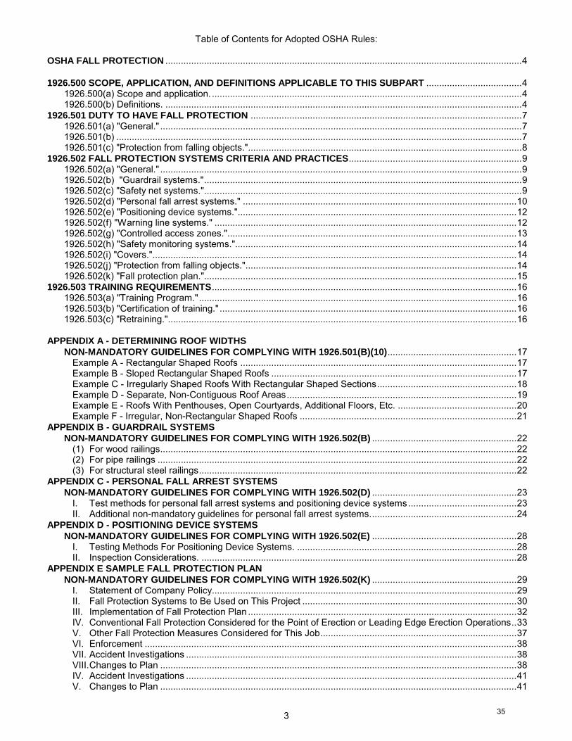
Table of Contents for Adopted OSHA Rules: OSHA FALL PROTECTION .......................................................................................................................................... 4
1926.500 SCOPE, APPLICATION, AND DEFINITIONS APPLICABLE TO THIS SUBPART ..................................... 4 1926.500(a) Scope and application. ........................................................................................................................ 4 1926.500(b) Definitions. .......................................................................................................................................... 4
1926.501 DUTY TO HAVE FALL PROTECTION ......................................................................................................... 7 1926.501(a) "General." ............................................................................................................................................ 7 1926.501(b) ............................................................................................................................................................. 7 1926.501(c) "Protection from falling objects.".......................................................................................................... 8
1926.502 FALL PROTECTION SYSTEMS CRITERIA AND PRACTICES ................................................................... 9 1926.502(a) "General." ............................................................................................................................................ 9 1926.502(b) "Guardrail systems." ........................................................................................................................... 9 1926.502(c) "Safety net systems." ........................................................................................................................... 9 1926.502(d) "Personal fall arrest systems." .......................................................................................................... 10 1926.502(e) "Positioning device systems." ............................................................................................................ 12 1926.502(f) "Warning line systems." ..................................................................................................................... 12 1926.502(g) "Controlled access zones."................................................................................................................ 13 1926.502(h) "Safety monitoring systems."............................................................................................................. 14 1926.502(i) "Covers." ............................................................................................................................................. 14 1926.502(j) "Protection from falling objects."......................................................................................................... 14 1926.502(k) "Fall protection plan."......................................................................................................................... 15
1926.503 TRAINING REQUIREMENTS ...................................................................................................................... 16 1926.503(a) "Training Program." ........................................................................................................................... 16 1926.503(b) "Certification of training." ................................................................................................................... 16 1926.503(c) "Retraining." ....................................................................................................................................... 16
APPENDIX A - DETERMINING ROOF WIDTHS
NON-MANDATORY GUIDELINES FOR COMPLYING WITH 1926.501(B)(10) .................................................. 17 Example A - Rectangular Shaped Roofs ........................................................................................................... 17 Example B - Sloped Rectangular Shaped Roofs ............................................................................................... 17 Example C - Irregularly Shaped Roofs With Rectangular Shaped Sections ...................................................... 18 Example D - Separate, Non-Contiguous Roof Areas ......................................................................................... 19 Example E - Roofs With Penthouses, Open Courtyards, Additional Floors, Etc. .............................................. 20 Example F - Irregular, Non-Rectangular Shaped Roofs .................................................................................... 21
APPENDIX B - GUARDRAIL SYSTEMS
NON-MANDATORY GUIDELINES FOR COMPLYING WITH 1926.502(B) ........................................................ 22 (1) For wood railings .......................................................................................................................................... 22 (2) For pipe railings ........................................................................................................................................... 22 (3) For structural steel railings ........................................................................................................................... 22
APPENDIX C - PERSONAL FALL ARREST SYSTEMS
NON-MANDATORY GUIDELINES FOR COMPLYING WITH 1926.502(D) ........................................................ 23 I. Test methods for personal fall arrest systems and positioning device systems .......................................... 23 II. Additional non-mandatory guidelines for personal fall arrest systems. ........................................................ 24
APPENDIX D - POSITIONING DEVICE SYSTEMS
NON-MANDATORY GUIDELINES FOR COMPLYING WITH 1926.502(E) ........................................................ 28 I. Testing Methods For Positioning Device Systems. ..................................................................................... 28 II. Inspection Considerations. .......................................................................................................................... 28
APPENDIX E SAMPLE FALL PROTECTION PLAN
NON-MANDATORY GUIDELINES FOR COMPLYING WITH 1926.502(K) ........................................................ 29 I. Statement of Company Policy ...................................................................................................................... 29 II. Fall Protection Systems to Be Used on This Project ................................................................................... 30 III. Implementation of Fall Protection Plan ........................................................................................................ 32 IV. Conventional Fall Protection Considered for the Point of Erection or Leading Edge Erection Operations .. 33 V. Other Fall Protection Measures Considered for This Job ............................................................................ 37 VI. Enforcement ................................................................................................................................................ 38 VII. Accident Investigations ................................................................................................................................ 38 VIII. Changes to Plan .......................................................................................................................................... 38 IV. Accident Investigations ................................................................................................................................ 41 V. Changes to Plan .......................................................................................................................................... 41
35
4
OSHA FALL PROTECTION
1926.500
SCOPE, APPLICATION, AND DEFINITIONS APPLICABLE TO THIS SUBPART
1926.500(a) Scope and application. 1926.500(a)(1) This subpart sets forth requirements and criteria for fall protection in construction workplaces
covered under 29 CFR part 1926. Exception: The provisions of this subpart do not apply when employees are making an inspection, investigation, or assessment of workplace conditions prior to the actual start of construction work or after all construction work has been completed.
1926.500(a)(2) Section 1926.501 sets forth those workplaces, conditions, operations, and circumstances for which fall protection shall be provided except as follows:
1926.500(a)(2)(i) Requirements relating to fall protection for employees working on scaffolds are provided in subpart L of this part.
1926.500(a)(2)(ii) Requirements relating to fall protection for employees working on cranes and derricks are provided in subpart CC of this part.
1926.500(a)(2)(iii) Fall protection requirements for employees performing steel erection work (except for towers and tanks) are provided in subpart R of this part.
1926.500(a)(2)(iv) Requirements relating to fall protection for employees working on certain types of equipment used in tunneling operations are provided in subpart S of this part.
1926.500(a)(2)(v) Requirements relating to fall protection for employees engaged in the erection of tanks and communication and broadcast towers are provided in § 1926.105.
1926.500(a)(2)(vi) Subpart V of this part provides requirements relating to fall protection for employees working from aerial lifts or on poles, towers, or similar structures while engaged in the construction of electric transmission or distribution lines or equipment.
1926.500(a)(2)(vii) Requirements relating to fall protection for employees working on stairways and ladders are provided in subpart X of this part.
1926.500(a)(3) Section 1926.502 sets forth the requirements for the installation, construction, and proper use of fall protection required by part 1926, except as follows:
1926.500(a)(3)(i) Performance requirements for guardrail systems used on scaffolds and performance requirements for falling object protection used on scaffolds are provided in subpart L of this part.
1926.500(a)(3)(ii) Performance requirements for stairways, stairrail systems, and handrails are provided in subpart X of this part.
1926.500(a)(3)(iii) Additional performance requirements for fall arrest and workpositioning equipment are provided in Subpart V of this part.
1926.500(a)(3)(iv) Section 1926.502 does not apply to the erection of tanks and communication and broadcast towers. (Note: Section 1926.104 sets the criteria for body belts, lanyards and lifelines used for fall protection during tank and communication and broadcast tower erection. Paragraphs (b),(c) and (f) of § 1926.107 provide definitions for the pertinent terms.) 1926.500(a)(3)(v) Criteria for steps, handholds, ladders, and grabrails/guardrails/railings required by subpart CC are provided in subpart CC. Sections 1926.502(a), (c) through (e), and (i) apply to activities covered under subpart CC unless otherwise stated in subpart CC. No other paragraphs of § 1926.502 apply to subpart CC.
1926.500(a)(4) Section 1926.503 sets forth requirements for training in the installation and use of fall protection systems, except in relation to steel erection activities and the use of equipment covered by subpart CC.
1926.500(b) Definitions. Anchorage means a secure point of attachment for lifelines, lanyards or deceleration devices. Body belt (safety belt) means a strap with means both for securing it about the waist and for attaching it to a
lanyard, lifeline, or deceleration device. Body harness means straps which may be secured about the employee in a manner that will distribute the fall arrest
forces over at least the thighs, pelvis, waist, chest and shoulders with means for attaching it to other components of a personal fall arrest system.
Buckle means any device for holding the body belt or body harness closed around the employee's body. Connector means a device which is used to couple (connect) parts of the personal fall arrest system and positioning
device systems together. It may be an independent component of the system, such as a carabiner, or it may be an integral component of part of the system (such as a buckle or dee-ring sewn into a body belt or body harness, or a snap-hook spliced or sewn to a lanyard or self-retracting lanyard).
Controlled access zone (CAZ) means an area in which certain work (e.g., overhand bricklaying) may take place without the use of guardrail systems, personal fall arrest systems, or safety net systems and access to the zone is controlled.
36

5
Dangerous equipment means equipment (such as pickling or galvanizing tanks, degreasing units, machinery, electrical equipment, and other units) which, as a result of form or function, may be hazardous to employees who fall onto or into such equipment.
Deceleration device means any mechanism, such as a rope grab, rip-stitch lanyard, specially-woven lanyard, tearing or deforming lanyards, automatic self-retracting lifelines/lanyards, etc., which serves to dissipate a substantial amount of energy during a fall arrest, or otherwise limit the energy imposed on an employee during fall arrest.
Deceleration distance means the additional vertical distance a falling employee travels, excluding lifeline elongation and free fall distance, before stopping, from the point at which the deceleration device begins to operate. It is measured as the distance between the location of an employee's body belt or body harness attachment point at the moment of activation (at the onset of fall arrest forces) of the deceleration device during a fall, and the location of that attachment point after the employee comes to a full stop.
Equivalent means alternative designs, materials, or methods to protect against a hazard which the employer can demonstrate will provide an equal or greater degree of safety for employees than the methods, materials or designs specified in the standard.
Failure means load refusal, breakage, or separation of component parts. Load refusal is the point where the ultimate strength is exceeded.
Free fall means the act of falling before a personal fall arrest system begins to apply force to arrest the fall. Free fall distance means the vertical displacement of the fall arrest attachment point on the employee's body belt or
body harness between onset of the fall and just before the system begins to apply force to arrest the fall. This distance excludes deceleration distance, and lifeline/lanyard elongation, but includes any deceleration device slide distance or self-retracting lifeline/lanyard extension before they operate and fall arrest forces occur.
Guardrail system means a barrier erected to prevent employees from falling to lower levels. Hole means a gap or void 2 inches (5.1 cm) or more in its least dimension, in a floor, roof, or other walking/working
surface. Infeasible means that it is impossible to perform the construction work using a conventional fall protection system
(i.e., guardrail system, safety net system, or personal fall arrest system) or that it is technologically impossible to use any one of these systems to provide fall protection.
Lanyard means a flexible line of rope, wire rope, or strap which generally has a connector at each end for connecting the body belt or body harness to a deceleration device, lifeline, or anchorage.
Leading edge means the edge of a floor, roof, or formwork for a floor or other walking/working surface (such as the deck) which changes location as additional floor, roof, decking, or formwork sections are placed, formed, or constructed. A leading edge is considered to be an "unprotected side and edge" during periods when it is not actively and continuously under construction.
Lifeline means a component consisting of a flexible line for connection to an anchorage at one end to hang vertically (vertical lifeline), or for connection to anchorages at both ends to stretch horizontally (horizontal lifeline), and which serves as a means for connecting other components of a personal fall arrest system to the anchorage.
Low-slope roof means a roof having a slope less than or equal to 4 in 12 (vertical to horizontal). Lower levels means those areas or surfaces to which an employee can fall. Such areas or surfaces include, but are
not limited to, ground levels, floors, platforms, ramps, runways, excavations, pits, tanks, material, water, equipment, structures, or portions thereof.
Mechanical equipment means all motor or human propelled wheeled equipment used for roofing work, except wheelbarrows and mopcarts.
Opening means a gap or void 30 inches (76 cm) or more high and 18 inches (48 cm) or more wide, in a wall or partition, through which employees can fall to a lower level.
Overhand bricklaying and related work means the process of laying bricks and masonry units such that the surface of the wall to be jointed is on the opposite side of the wall from the mason, requiring the mason to lean over the wall to complete the work. Related work includes mason tending and electrical installation incorporated into the brick wall during the overhand bricklaying process.
Personal fall arrest system means a system used to arrest an employee in a fall from a working level. It consists of an anchorage, connectors, a body belt or body harness and may include a lanyard, deceleration device, lifeline, or suitable combinations of these. As of January 1, 1998, the use of a body belt for fall arrest is prohibited.
Positioning device system means a body belt or body harness system rigged to allow an employee to be supported on an elevated vertical surface, such as a wall, and work with both hands free while leaning.
Rope grab means a deceleration device which travels on a lifeline and automatically, by friction, engages the lifeline and locks so as to arrest the fall of an employee. A rope grab usually employs the principle of inertial locking, cam/level locking, or both.
Roof means the exterior surface on the top of a building. This does not include floors or formwork which, because a building has not been completed, temporarily become the top surface of a building.
37
6
Roofing work means the hoisting, storage, application, and removal of roofing materials and equipment, includingrelated insulation, sheet metal, and vapor barrier work, but not including the construction of the roof deck.
Safety-monitoring system means a safety system in which a competent person is responsible for recognizing andwarning employees of fall hazards.
Self-retracting lifeline/lanyard means a deceleration device containing a drum-wound line which can be slowlyextracted from, or retracted onto, the drum under slight tension during normal employee movement, andwhich, after onset of a fall, automatically locks the drum and arrests the fall.
Snaphook means a connector comprised of a hook-shaped member with a normally closed keeper, or similararrangement, which may be opened to permit the hook to receive an object and, when released,automatically closes to retain the object. Snaphooks are generally one of two types:
1926.500(b)(1) The locking type with a self-closing, self-locking keeper which remains closed and locked untilunlocked and pressed open for connection or disconnection; or
1926.500(b)(2) The non-locking type with a self-closing keeper which remains closed until pressed open forconnection or disconnection. As of January 1, 1998, the use of a non-locking snaphook as part of personalfall arrest systems and positioning device systems is prohibited.
Steep roof means a roof having a slope greater than 4 in 12 (vertical to horizontal).Toeboard means a low protective barrier that will prevent the fall of materials and equipment to lower levels and
provide protection from falls for personnel.Unprotected sides and edges means any side or edge (except at entrances to points of access) of a
walking/working surface, e.g., floor, roof, ramp, or runway where there is no wall or guardrail system at least39 inches (1.0 m) high.
Walking/working surface means any surface, whether horizontal or vertical on which an employee walks or works,including, but not limited to, floors, roofs, ramps, bridges, runways, formwork and concrete reinforcing steelbut not including ladders, vehicles, or trailers, on which employees must be located in order to perform theirjob duties.
Warning line system means a barrier erected on a roof to warn employees that they are approaching an unprotectedroof side or edge, and which designates an area in which roofing work may take place without the use ofguardrail, body belt, or safety net systems to protect employees in the area.
Work area means that portion of a walking/working surface where job duties are being performed.
[44 FR 8577, Feb. 9, 1979; 44 FR 20940, Apr. 6, 1979, as amended at 45 FR 75625, Nov. 14. 1980; 55 FR 47687,Nov. 14, 1990; 59 FR 40730, Aug. 9, 1994; 60 FR 5131, Jan. 26, 1995; 60 FR 39254, Aug. 2, 1995; 66 FR 5265,Jan. 18, 2001; 75 FR 48133, Aug. 9, 2010; 79 FR 20696, July 10, 2014]
38
7
1926.501
DUTY TO HAVE FALL PROTECTION
1926.501(a) "General." 1926.501(a)(1) This section sets forth requirements for employers to provide fall protection systems. All fall protection
required by this section shall conform to the criteria set forth in 1926.502 of this subpart. 1926.501(a)(2) The employer shall determine if the walking/working surfaces on which its employees are to work have
the strength and structural integrity to support employees safely. Employees shall be allowed to work on those surfaces only when the surfaces have the requisite strength and structural integrity.
1926.501(b)
1926.501(b)(1) "Unprotected sides and edges." Each employee on a walking/working surface (horizontal and vertical surface) with an unprotected side or edge which is 6 feet (1.8 m) or more above a lower level shall be protected from falling by the use of guardrail systems, safety net systems, or personal fall arrest systems.
1926.501(b)(2) "Leading edges." 1926.501(b)(2)(i) Each employee who is constructing a leading edge 6 feet (1.8 m) or more above lower levels shall
be protected from falling by guardrail systems, safety net systems, or personal fall arrest systems. Exception: When the employer can demonstrate that it is infeasible or creates a greater hazard to use these systems, the employer shall develop and implement a fall protection plan which meets the requirements of paragraph (k) of 1926.502.
Note: There is a presumption that it is feasible and will not create a greater hazard to implement at least one of the above-listed fall protection systems. Accordingly, the employer has the burden of establishing that it is appropriate to implement a fall protection plan which complies with 1926.502(k) for a particular workplace situation, in lieu of implementing any of those systems.
1926.501(b)(2)(ii) Each employee on a walking/working surface 6 feet (1.8 m) or more above a lower level where leading edges are under construction, but who is not engaged in the leading edge work, shall be protected from falling by a guardrail system, safety net system, or personal fall arrest system. If a guardrail system is chosen to provide the fall protection, and a controlled access zone has already been established for leading edge work, the control line may be used in lieu of a guardrail along the edge that parallels the leading edge.
1926.501(b)(3) "Hoist areas." Each employee in a hoist area shall be protected from falling 6 feet (1.8 m) or more to lower levels by guardrail systems or personal fall arrest systems. If guardrail systems, [or chain, gate, or guardrail] or portions thereof, are removed to facilitate the hoisting operation (e.g., during landing of materials), and an employee must lean through the access opening or out over the edge of the access opening (to receive or guide equipment and materials, for example), that employee shall be protected from fall hazards by a personal fall arrest system.
1926.501(b)(4) "Holes." 1926.501(b)(4)(i) Each employee on walking/working surfaces shall be protected from falling through holes (including
skylights) more than 6 feet (1.8 m) above lower levels, by personal fall arrest systems, covers, or guardrail systems erected around such holes.
1926.501(b)(4)(ii) Each employee on a walking/working surface shall be protected from tripping in or stepping into or through holes (including skylights) by covers.
1926.501(b)(4)(iii) Each employee on a walking/working surface shall be protected from objects falling through holes (including skylights) by covers.
1926.501(b)(5) "Formwork and reinforcing steel." Each employee on the face of formwork or reinforcing steel shall be protected from falling 6 feet (1.8 m) or more to lower levels by personal fall arrest systems, safety net systems, or positioning device systems.
1926.501(b)(6) "Ramps, runways, and other walkways." Each employee on ramps, runways, and other walkways shall be protected from falling 6 feet (1.8 m) or more to lower levels by guardrail systems.
1926.501(b)(7) "Excavations." 1926.501(b)(7)(i) Each employee at the edge of an excavation 6 feet (1.8 m) or more in depth shall be protected from
falling by guardrail systems, fences, or barricades when the excavations are not readily seen because of plant growth or other visual barrier;
1926.501(b)(7)(ii) Each employee at the edge of a well, pit, shaft, and similar excavation 6 feet (1.8 m) or more in depth shall be protected from falling by guardrail systems, fences, barricades, or covers.
1926.501(b)(8) "Dangerous equipment." 1926.501(b)(8)(i) Each employee less than 6 feet (1.8 m) above dangerous equipment shall be protected from falling
into or onto the dangerous equipment by guardrail systems or by equipment guards. 1926.501(b)(8)(ii) Each employee 6 feet (1.8 m) or more above dangerous equipment shall be protected from fall
hazards by guardrail systems, personal fall arrest systems, or safety net systems.
39
8
1926.501(b)(9) "Overhand bricklaying and related work." 1926.501(b)(9)(i) Except as otherwise provided in paragraph (b) of this section, each employee performing overhand
bricklaying and related work 6 feet (1.8 m) or more above lower levels, shall be protected from falling by guardrail systems, safety net systems, personal fall arrest systems, or shall work in a controlled access zone.
1926.501(b)(9)(ii) Each employee reaching more than 10 inches (25 cm) below the level of the walking/working surface on which they are working, shall be protected from falling by a guardrail system, safety net system, or personal fall arrest system.
Note: Bricklaying operations performed on scaffolds are regulated by subpart L - Scaffolds of this part. 1926.501(b)(10) "Roofing work on Low-slope roofs." Except as otherwise provided in paragraph (b) of this
section, each employee engaged in roofing activities on low-slope roofs, with unprotected sides and edges 6 feet (1.8 m) or more above lower levels shall be protected from falling by guardrail systems, safety net systems, personal fall arrest systems, or a combination of warning line system and guardrail system, warning line system and safety net system, or warning line system and personal fall arrest system, or warning line system and safety monitoring system. Or, on roofs 50-feet (15.25 m) or less in width (see Appendix A to subpart M of this part), the use of a safety monitoring system alone [i.e. without the warning line system] is permitted.
1926.501(b)(11) "Steep roofs." Each employee on a steep roof with unprotected sides and edges 6 feet (1.8 m) or more above lower levels shall be protected from falling by guardrail systems with toeboards, safety net systems, or personal fall arrest systems.
1926.501(b)(12) "Precast concrete erection." Each employee engaged in the erection of precast concrete members (including, but not limited to the erection of wall panels, columns, beams, and floor and roof "tees") and related operations such as grouting of precast concrete members, who is 6 feet (1.8 m) or more above lower levels shall be protected from falling by guardrail systems, safety net systems, or personal fall arrest systems, unless another provision in paragraph (b) of this section provides for an alternative fall protection measure. Exception: When the employer can demonstrate that it is infeasible or creates a greater hazard to use these systems, the employer shall develop and implement a fall protection plan which meets the requirements of paragraph (k) of 1926.502.
Note: There is a presumption that it is feasible and will not create a greater hazard to implement at least one of the above-listed fall protection systems. Accordingly, the employer has the burden of establishing that it is appropriate to implement a fall protection plan which complies with 1926.502(k) for a particular workplace situation, in lieu of implementing any of those systems.
1926.501(b)(13) "Residential construction." Each employee engaged in residential construction activities 6 feet (1.8 m) or more above lower levels shall be protected by guardrail systems, safety net system, or personal fall arrest system unless another provision in paragraph (b) of this section provides for an alternative fall protection measure. Exception: When the employer can demonstrate that it is infeasible or creates a greater hazard to use these systems, the employer shall develop and implement a fall protection plan which meets the requirements of paragraph (k) of 1926.502.
Note: There is a presumption that it is feasible and will not create a greater hazard to implement at least one of the above-listed fall protection systems. Accordingly, the employer has the burden of establishing that it is appropriate to implement a fall protection plan which complies with 1926.502(k) for a particular workplace situation, in lieu of implementing any of those systems.
1926.501(b)(14) "Wall openings." Each employee working on, at, above, or near wall openings (including those with chutes attached) where the outside bottom edge of the wall opening is 6 feet (1.8 m) or more above lower levels and the inside bottom edge of the wall opening is less than 39 inches (1.0 m) above the walking/working surface, shall be protected from falling by the use of a guardrail system, a safety net system, or a personal fall arrest system.
1926.501(b)(15) "Walking/working surfaces not otherwise addressed." Except as provided in 1926.500(a)(2) or in 1926.501 (b)(1) through (b)(14), each employee on a walking/working surface 6 feet (1.8 m) or more above lower levels shall be protected from falling by a guardrail system, safety net system, or personal fall arrest system.
1926.501(c) "Protection from falling objects." When an employee is exposed to falling objects, the employer shall have each employee wear a hard hat and shall
implement one of the following measures: 1926.501(c)(1) Erect toeboards, screens, or guardrail systems to prevent objects from falling from higher levels; or, 1926.501(c)(2) Erect a canopy structure and keep potential fall objects far enough from the edge of the higher level so
that those objects would not go over the edge if they were accidentally displaced; or, 1926.501(c)(3) Barricade the area to which objects could fall, prohibit employees from entering the barricaded area,
and keep objects that may fall far enough away from the edge of a higher level so that those objects would not go over the edge if they were accidentally displaced.
[59 FR 40732, Aug. 9, 1994; 60 FR 5131, Jan. 26, 1995]
40
9
1926.502
FALL PROTECTION SYSTEMS CRITERIA AND PRACTICES 1926.502(a) "General." 1926.502(a)(1) Fall protection systems required by this part shall comply with the applicable provisions of this section. 1926.502(a)(2) Employers shall provide and install all fall protection systems required by this subpart for an employee,
and shall comply with all other pertinent requirements of this subpart before that employee begins the work that necessitates the fall protection.
1926.502(b) "Guardrail systems." Guardrail systems and their use shall comply with the following provisions: 1926.502(b)(1) Top edge height of top rails, or equivalent guardrail system members, shall be 42 inches (1.1 m) plus
or minus 3 inches (8 cm) above the walking/working level. When conditions warrant, the height of the top edge may exceed the 45-inch height, provided the guardrail system meets all other criteria of this paragraph.
Note: When employees are using stilts, the top edge height of the top rail, or equivalent member, shall be increased an amount equal to the height of the stilts.
1926.502(b)(2) Midrails, screens, mesh, intermediate vertical members, or equivalent intermediate structural members shall be installed between the top edge of the guardrail system and the walking/working surface when there is no wall or parapet wall at least 21 inches (53 cm) high.
1926.502(b)(2)(i) Midrails, when used, shall be installed at a height midway between the top edge of the guardrail system and the walking/working level.
1926.502(b)(2)(ii) Screens and mesh, when used, shall extend from the top rail to the walking/working level and along the entire opening between top rail supports.
1926.502(b)(2)(iii) Intermediate members (such as balusters), when used between posts, shall be not more than 19 inches (48 cm) apart.
1926.502(b)(2)(iv) Other structural members (such as additional midrails and architectural panels) shall be installed such that there are no openings in the guardrail system that are more than 19 inches (.5 m) wide.
1926.502(b)(3) Guardrail systems shall be capable of withstanding, without failure, a force of at least 200 pounds (890 N) applied within 2 inches (5.1 cm) of the top edge, in any outward or downward direction, at any point along the top edge.
1926.502(b)(4) When the 200 pound (890 N) test load specified in paragraph (b)(3) of this section is applied in a downward direction, the top edge of the guardrail shall not deflect to a height less than 39 inches (1.0 m) above the walking/working level. Guardrail system components selected and constructed in accordance with the Appendix B to subpart M of this part will be deemed to meet this requirement.
1926.502(b)(5) Midrails, screens, mesh, intermediate vertical members, solid panels, and equivalent structural members shall be capable of withstanding, without failure, a force of at least 150 pounds (666 N) applied in any downward or outward direction at any point along the midrail or other member.
1926.502(b)(6) Guardrail systems shall be so surfaced as to prevent injury to an employee from punctures or lacerations, and to prevent snagging of clothing.
1926.502(b)(7) The ends of all top rails and midrails shall not overhang the terminal posts, except where such overhang does not constitute a projection hazard.
1926.502(b)(8) Steel banding and plastic banding shall not be used as top rails or midrails. 1926.502(b)(9) Top rails and midrails shall be at least one-quarter inch (0.6 cm) nominal diameter or thickness to
prevent cuts and lacerations. If wire rope is used for top rails, it shall be flagged at not more than 6-foot intervals with high-visibility material.
1926.502(b)(10) When guardrail systems are used at hoisting areas, a chain, gate or removable guardrail section shall be placed across the access opening between guardrail sections when hoisting operations are not taking place.
1926.502(b)(11) When guardrail systems are used at holes, they shall be erected on all unprotected sides or edges of the hole.
1926.502(b)(12) When guardrail systems are used around holes used for the passage of materials, the hole shall have not more than two sides provided with removable guardrail sections to allow the passage of materials. When the hole is not in use, it shall be closed over with a cover, or a guardrail system shall be provided along all unprotected sides or edges.
1926.502(b)(13) When guardrail systems are used around holes which are used as points of access (such as ladderways), they shall be provided with a gate, or be so offset that a person cannot walk directly into the hole.
1926.502(b)(14) Guardrail systems used on ramps and runways shall be erected along each unprotected side or edge. 1926.502(b)(15) Manila, plastic or synthetic rope being used for top rails or midrails shall be inspected as frequently as
necessary to ensure that it continues to meet the strength requirements of paragraph (b)(3) of this section.
41
10
1926.502(c) "Safety net systems." Safety net systems and their use shall comply with the following provisions: 1926.502(c)(1) Safety nets shall be installed as close as practicable under the walking/working surface on which
employees are working, but in no case more than 30 feet (9.1 m) below such level. When nets are used on bridges, the potential fall area from the walking/working surface to the net shall be unobstructed.
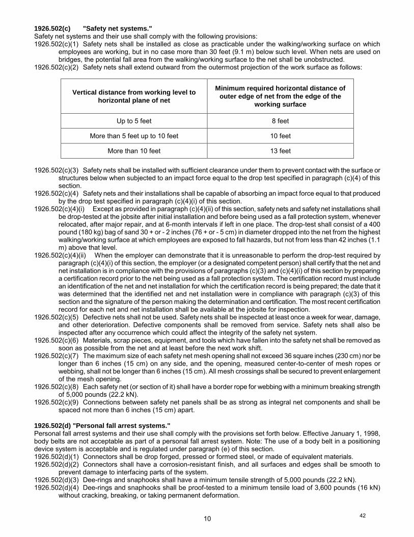
1926.502(c)(2) Safety nets shall extend outward from the outermost projection of the work surface as follows:
Vertical distance from working level to
horizontal plane of net
Minimum required horizontal distance of
outer edge of net from the edge of the
working surface
Up to 5 feet 8 feet
More than 5 feet up to 10 feet 10 feet
More than 10 feet 13 feet
1926.502(c)(3) Safety nets shall be installed with sufficient clearance under them to prevent contact with the surface or
structures below when subjected to an impact force equal to the drop test specified in paragraph (c)(4) of this section.
1926.502(c)(4) Safety nets and their installations shall be capable of absorbing an impact force equal to that produced by the drop test specified in paragraph (c)(4)(i) of this section.
1926.502(c)(4)(i) Except as provided in paragraph (c)(4)(ii) of this section, safety nets and safety net installations shall be drop-tested at the jobsite after initial installation and before being used as a fall protection system, whenever relocated, after major repair, and at 6-month intervals if left in one place. The drop-test shall consist of a 400 pound (180 kg) bag of sand 30 + or - 2 inches (76 + or - 5 cm) in diameter dropped into the net from the highest walking/working surface at which employees are exposed to fall hazards, but not from less than 42 inches (1.1 m) above that level.
1926.502(c)(4)(ii) When the employer can demonstrate that it is unreasonable to perform the drop-test required by paragraph (c)(4)(i) of this section, the employer (or a designated competent person) shall certify that the net and net installation is in compliance with the provisions of paragraphs (c)(3) and (c)(4)(i) of this section by preparing a certification record prior to the net being used as a fall protection system. The certification record must include an identification of the net and net installation for which the certification record is being prepared; the date that it was determined that the identified net and net installation were in compliance with paragraph (c)(3) of this section and the signature of the person making the determination and certification. The most recent certification record for each net and net installation shall be available at the jobsite for inspection.
1926.502(c)(5) Defective nets shall not be used. Safety nets shall be inspected at least once a week for wear, damage, and other deterioration. Defective components shall be removed from service. Safety nets shall also be inspected after any occurrence which could affect the integrity of the safety net system.
1926.502(c)(6) Materials, scrap pieces, equipment, and tools which have fallen into the safety net shall be removed as soon as possible from the net and at least before the next work shift.
1926.502(c)(7) The maximum size of each safety net mesh opening shall not exceed 36 square inches (230 cm) nor be longer than 6 inches (15 cm) on any side, and the opening, measured center-to-center of mesh ropes or webbing, shall not be longer than 6 inches (15 cm). All mesh crossings shall be secured to prevent enlargement of the mesh opening.
1926.502(c)(8) Each safety net (or section of it) shall have a border rope for webbing with a minimum breaking strength of 5,000 pounds (22.2 kN).
1926.502(c)(9) Connections between safety net panels shall be as strong as integral net components and shall be spaced not more than 6 inches (15 cm) apart.
1926.502(d) "Personal fall arrest systems." Personal fall arrest systems and their use shall comply with the provisions set forth below. Effective January 1, 1998, body belts are not acceptable as part of a personal fall arrest system. Note: The use of a body belt in a positioning device system is acceptable and is regulated under paragraph (e) of this section. 1926.502(d)(1) Connectors shall be drop forged, pressed or formed steel, or made of equivalent materials. 1926.502(d)(2) Connectors shall have a corrosion-resistant finish, and all surfaces and edges shall be smooth to
prevent damage to interfacing parts of the system. 1926.502(d)(3) Dee-rings and snaphooks shall have a minimum tensile strength of 5,000 pounds (22.2 kN). 1926.502(d)(4) Dee-rings and snaphooks shall be proof-tested to a minimum tensile load of 3,600 pounds (16 kN)
without cracking, breaking, or taking permanent deformation.
42
11
1926.502(d)(5) Snaphooks shall be sized to be compatible with the member to which they are connected to prevent unintentional disengagement of the snaphook by depression of the snaphook keeper by the connected member, or shall be a locking type snaphook designed and used to prevent disengagement of the snaphook by the contact of the snaphook keeper by the connected member. Effective January 1, 1998, only locking type snaphooks shall be used.
1926.502(d)(6) Unless the snaphook is a locking type and designed for the following connections, snaphooks shall not be engaged:
1926.502(d)(6)(i) directly to webbing, rope or wire rope; 1926.502(d)(6)(ii) to each other; 1926.502(d)(6)(iii) to a dee-ring to which another snaphook or other connector is attached; 1926.502(d)(6)(iv) to a horizontal lifeline; or 1926.502(d)(6)(v) to any object which is incompatibly shaped or dimensioned in relation to the snaphook such that
unintentional disengagement could occur by the connected object being able to depress the snaphook keeper and release itself.
1926.502(d)(7) On suspended scaffolds or similar work platforms with horizontal lifelines which may become vertical lifelines, the devices used to connect to a horizontal lifeline shall be capable of locking in both directions on the lifeline.
1926.502(d)(8) Horizontal lifelines shall be designed, installed, and used, under the supervision of a qualified person, as part of a complete personal fall arrest system, which maintains a safety factor of at least two.
1926.502(d)(9) Lanyards and vertical lifelines shall have a minimum breaking strength of 5,000 pounds (22.2 kN). 1926.502(d)(10) 1926.502(d)(10)(i) Except as provided in paragraph (d)(10)(ii) of this section, when vertical lifelines are used, each
employee shall be attached to a separate lifeline. 1926.502(d)(10)(ii) During the construction of elevator shafts, two employees may be attached to the same lifeline in the
hoistway, provided both employees are working atop a false car that is equipped with guardrails; the strength of the lifeline is 10,000 pounds [5,000 pounds per employee attached] (44.4 kN); and all other criteria specified in this paragraph for lifelines have been met.
1926.502(d)(11) Lifelines shall be protected against being cut or abraded. 1926.502(d)(12) Self-retracting lifelines and lanyards which automatically limit free fall distance to 2 feet (0.61 m) or less
shall be capable of sustaining a minimum tensile load of 3,000 pounds (13.3 kN) applied to the device with the lifeline or lanyard in the fully extended position.
1926.502(d)(13) Self-retracting lifelines and lanyards which do not limit free fall distance to 2 feet (0.61 m) or less, ripstitch lanyards, and tearing and deforming lanyards shall be capable of sustaining a minimum tensile load of 5,000 pounds (22.2 kN) applied to the device with the lifeline or lanyard in the fully extended position.
1926.502(d)(14) Ropes and straps (webbing) used in lanyards, lifelines, and strength components of body belts and body harnesses shall be made from synthetic fibers.
1926.502(d)(15) Anchorages used for attachment of personal fall arrest equipment shall be independent of any anchorage being used to support or suspend platforms and capable of supporting at least 5,000 pounds (22.2 kN) per employee attached, or shall be designed, installed, and used as follows:
1926.502(d)(15)(i) as part of a complete personal fall arrest system which maintains a safety factor of at least two; and 1926.502(d)(15)(ii) under the supervision of a qualified person. 1926.502(d)(16) Personal fall arrest systems, when stopping a fall, shall: 1926.502(d)(16)(i) limit maximum arresting force on an employee to 900 pounds (4 kN) when used with a body belt; 1926.502(d)(16)(ii) limit maximum arresting force on an employee to 1,800 pounds (8 kN) when used with a body
harness; 1926.502(d)(16)(iii) be rigged such that an employee can neither free fall more than 6 feet (1.8 m), nor contact any lower
level; 1926.502(d)(16)(iv) bring an employee to a complete stop and limit maximum deceleration distance an employee travels
to 3.5 feet (1.07 m); and, 1926.502(d)(16)(v) have sufficient strength to withstand twice the potential impact energy of an employee free falling a
distance of 6 feet (1.8 m), or the free fall distance permitted by the system, whichever is less. Note: If the personal fall arrest system meets the criteria and protocols contained in Appendix C to subpart M, and if the
system is being used by an employee having a combined person and tool weight of less than 310 pounds (140 kg), the system will be considered to be in compliance with the provisions of paragraph (d)(16) of this section. If the system is used by an employee having a combined tool and body weight of 310 pounds (140 kg) or more, then the employer must appropriately modify the criteria and protocols of the Appendix to provide proper protection for such heavier weights, or the system will not be deemed to be in compliance with the requirements of paragraph (d)(16) of this section.
1926.502(d)(17) The attachment point of the body belt shall be located in the center of the wearer's back. The attachment point of the body harness shall be located in the center of the wearer's back near shoulder level, or above the wearer's head.
1926.502(d)(18) Body belts, harnesses, and components shall be used only for employee protection (as part of a personal fall arrest system or positioning device system) and not to hoist materials.
43
12
1926.502(d)(19) Personal fall arrest systems and components subjected to impact loading shall be immediately removed from service and shall not be used again for employee protection until inspected and determined by a competent person to be undamaged and suitable for reuse.
1926.502(d)(20) The employer shall provide for prompt rescue of employees in the event of a fall or shall assure that employees are able to rescue themselves.
1926.502(d)(21) Personal fall arrest systems shall be inspected prior to each use for wear, damage and other deterioration, and defective components shall be removed from service.
1926.502(d)(22) Body belts shall be at least one and five-eighths (1 5/8) inches (4.1 cm) wide. 1926.502(d)(23) Personal fall arrest systems shall not be attached to guardrail systems, nor shall they be attached to
hoists except as specified in other subparts of this Part. 1926.502(d)(24) When a personal fall arrest system is used at hoist areas, it shall be rigged to allow the movement of
the employee only as far as the edge of the walking/working surface. 1926.502(e) "Positioning device systems." Positioning device systems and their use shall conform to the following provisions: 1926.502(e)(1) Positioning devices shall be rigged such that an employee cannot free fall more than 2 feet (.6m). 1926.502(e)(2) Positioning devices shall be secured to an anchorage capable of supporting at least twice the potential
impact load of an employee's fall or 3,000 pounds (13.3 kN), whichever is greater. 1926.502(e)(3) Connectors shall be drop forged, pressed or formed steel, or made of equivalent materials. 1926.502(e)(4) Connectors shall have a corrosion-resistant finish, and all surfaces and edges shall be smooth to
prevent damage to interfacing parts of this system. 1926.502(e)(5) Connecting assemblies shall have a minimum tensile strength of 5,000 pounds (22.2 kN) 1926.502(e)(6) Dee-rings and snaphooks shall be proof-tested to a minimum tensile load of 3,600 pounds (16 kN)
without cracking, breaking, or taking permanent deformation. 1926.502(e)(7) Snaphooks shall be sized to be compatible with the member to which they are connected to prevent
unintentional disengagement of the snaphook by depression of the snaphook keeper by the connected member, or shall be a locking type snaphook designed and used to prevent disengagement of the snaphook by the contact of the snaphook keeper by the connected member. As of January 1, 1998, only locking type snaphooks shall be used.
1926.502(e)(8) Unless the snaphook is a locking type and designed for the following connections, snaphooks shall not be engaged:
1926.502(e)(8)(i) directly to webbing, rope or wire rope; 1926.502(e)(8)(ii) to each other; 1926.502(e)(8)(iii) to a dee-ring to which another snaphook or other connector is attached; 1926.502(e)(8)(iv) to a horizontal lifeline; or 1926.502(e)(8)(v) to any object which is incompatibly shaped or dimensioned in relation to the snaphook such that
unintentional disengagement could occur by the connected object being able to depress the snaphook keeper and release itself.
1926.502(e)(9) Positioning device systems shall be inspected prior to each use for wear, damage, and other deterioration, and defective components shall be removed from service.
1926.502(e)(10) Body belts, harnesses, and components shall be used only for employee protection (as part of a personal fall arrest system or positioning device system) and not to hoist materials.
1926.502(f) "Warning line systems." Warning line systems [See 1926.501(b)(10)] and their use shall comply with the following provisions: 1926.502(f)(1) The warning line shall be erected around all sides of the roof work area. 1926.502(f)(1)(i) When mechanical equipment is not being used, the warning line shall be erected not less than
6 feet (1.8 m) from the roof edge. 1926.502(f)(1)(ii) When mechanical equipment is being used, the warning line shall be erected not less than
6 feet (1.8 m) from the roof edge which is parallel to the direction of mechanical equipment operation, and not less than 10 feet (3.1 m) from the roof edge which is perpendicular to the direction of mechanical equipment operation.
1926.502(f)(1)(iii) Points of access, materials handling areas, storage areas, and hoisting areas shall be connected to the work area by an access path formed by two warning lines.
1926.502(f)(1)(iv) When the path to a point of access is not in use, a rope, wire, chain, or other barricade, equivalent in strength and height to the warning line, shall be placed across the path at the point where the path intersects the warning line erected around the work area, or the path shall be offset such that a person cannot walk directly into the work area.
1926.502(f)(2) Warning lines shall consist of ropes, wires, or chains, and supporting stanchions erected as follows: 1926.502(f)(2)(i) The rope, wire, or chain shall be flagged at not more than 6-foot (1.8 m) intervals with high-visibility
material;
44
13
1926.502(f)(2)(ii) The rope, wire, or chain shall be rigged and supported in such a way that its lowest point (including sag) is no less than 34 inches (.9 m) from the walking/working surface and its highest point is no more than 39 inches (1.0 m) from the walking/working surface;
1926.502(f)(2)(iii) After being erected, with the rope, wire, or chain attached, stanchions shall be capable of resisting, without tipping over, a force of at least 16 pounds (71 N) applied horizontally against the stanchion, 30 inches (.8 m) above the walking/working surface, perpendicular to the warning line, and in the direction of the floor, roof, or platform edge;
1926.502(f)(2)(iv) The rope, wire, or chain shall have a minimum tensile strength of 500 pounds (2.22 kN), and after being attached to the stanchions, shall be capable of supporting, without breaking, the loads applied to the stanchions as prescribed in paragraph (f)(2)(iii) of this section; and
1926.502(f)(2)(v) The line shall be attached at each stanchion in such a way that pulling on one section of the line between stanchions will not result in slack being taken up in adjacent sections before the stanchion tips over.
1926.502(f)(3) No employee shall be allowed in the area between a roof edge and a warning line unless the employee is performing roofing work in that area.
1926.502(f)(4) Mechanical equipment on roofs shall be used or stored only in areas where employees are protected by a warning line system, guardrail system, or personal fall arrest system.
1926.502(g) "Controlled access zones." Controlled access zones [See 1926.501(b)(9) and 1926.502(k)] and their use shall conform to the following provisions. 1926.502(g)(1) When used to control access to areas where leading edge and other operations are taking place the
controlled access zone shall be defined by a control line or by any other means that restricts access. 1926.502(g)(1)(i) When control lines are used, they shall be erected not less than 6 feet (1.8 m) nor more than
25 feet (7.7 m) from the unprotected or leading edge, except when erecting precast concrete members. 1926.502(g)(1)(ii) When erecting precast concrete members, the control line shall be erected not less than 6 feet (1.8
m) nor more than 60 feet (18 m) or half the length of the member being erected, whichever is less, from the leading edge.
1926.502(g)(1)(iii) The control line shall extend along the entire length of the unprotected or leading edge and shall be approximately parallel to the unprotected or leading edge.
1926.502(g)(1)(iv) The control line shall be connected on each side to a guardrail system or wall. 1926.502(g)(2) When used to control access to areas where overhand bricklaying and related work are taking place: 1926.502(g)(2)(i) The controlled access zone shall be defined by a control line erected not less than 10 feet (3.1 m)
nor more than 15 feet (4.5 m) from the working edge. 1926.502(g)(2)(ii) The control line shall extend for a distance sufficient for the controlled access zone to enclose all
employees performing overhand bricklaying and related work at the working edge and shall be approximately parallel to the working edge.
1926.502(g)(2)(iii) Additional control lines shall be erected at each end to enclose the controlled access zone. 1926.502(g)(2)(iv) Only employees engaged in overhand bricklaying or related work shall be permitted in the controlled
access zone. 1926.502(g)(3) Control lines shall consist of ropes, wires, tapes, or equivalent materials, and supporting stanchions as
follows: 1926.502(g)(3)(i) Each line shall be flagged or otherwise clearly marked at not more than 6-foot (1.8 m) intervals with
high-visibility material. 1926.502(g)(3)(ii) Each line shall be rigged and supported in such a way that its lowest point (including sag) is not less
than 39 inches (1 m) from the walking/working surface and its highest point is not more than 45 inches (1.3 m) [50 inches (1.3 m) when overhand bricklaying operations are being performed] from the walking/working surface.
1926.502(g)(3)(iii) Each line shall have a minimum breaking strength of 200 pounds (.88 kN). 1926.502(g)(4) On floors and roofs where guardrail systems are not in place prior to the beginning of overhand
bricklaying operations, controlled access zones shall be enlarged, as necessary, to enclose all points of access, material handling areas, and storage areas.
1926.502(g)(5) On floors and roofs where guardrail systems are in place, but need to be removed to allow overhand bricklaying work or leading edge work to take place, only that portion of the guardrail necessary to accomplish that day's work shall be removed.
45
14
1926.502(h) "Safety monitoring systems." Safety monitoring systems [See 1926.501(b)(10) and 1926.502(k)] and their use shall comply with the following provisions: 1926.502(h)(1) The employer shall designate a competent person to monitor the safety of other employees and the
employer shall ensure that the safety monitor complies with the following requirements: 1926.502(h)(1)(i) The safety monitor shall be competent to recognize fall hazards; 1926.502(h)(1)(ii) The safety monitor shall warn the employee when it appears that the employee is unaware of a fall
hazard or is acting in an unsafe manner; 1926.502(h)(1)(iii) The safety monitor shall be on the same walking/working surface and within visual sighting distance
of the employee being monitored; 1926.502(h)(1)(iv) The safety monitor shall be close enough to communicate orally with the employee; and 1926.502(h)(1)(v) The safety monitor shall not have other responsibilities which could take the monitor's attention from
the monitoring function. 1926.502(h)(2) Mechanical equipment shall not be used or stored in areas where safety monitoring systems are being
used to monitor employees engaged in roofing operations on low-slope roofs. 1926.502(h)(3) No employee, other than an employee engaged in roofing work [on low-sloped roofs] or an employee
covered by a fall protection plan, shall be allowed in an area where an employee is being protected by a safety monitoring system.
1926.502(h)(4) Each employee working in a controlled access zone shall be directed to comply promptly with fall hazard warnings from safety monitors.
1926.502(i) "Covers." Covers for holes in floors, roofs, and other walking/working surfaces shall meet the following requirements: 1926.502(i)(1) Covers located in roadways and vehicular aisles shall be capable of supporting, without failure, at least
twice the maximum axle load of the largest vehicle expected to cross over the cover. 1926.502(i)(2) All other covers shall be capable of supporting, without failure, at least twice the weight of employees,
equipment, and materials that may be imposed on the cover at any one time. 1926.502(i)(3) All covers shall be secured when installed so as to prevent accidental displacement by the wind,
equipment, or employees. 1926.502(i)(4) All covers shall be color coded or they shall be marked with the word "HOLE" or "COVER" to provide
warning of the hazard. Note: This provision does not apply to cast iron manhole covers or steel grates used on streets or roadways.
1926.502(j) "Protection from falling objects." Falling object protection shall comply with the following provisions: 1926.502(j)(1) Toeboards, when used as falling object protection, shall be erected along the edge of the overhead
walking/working surface for a distance sufficient to protect employees below. 1926.502(j)(2) Toeboards shall be capable of withstanding, without failure, a force of at least 50 pounds (222 N)
applied in any downward or outward direction at any point along the toeboard. 1926.502(j)(3) Toeboards shall be a minimum of 3 1/2 inches (9 cm) in vertical height from their top edge to the level
of the walking/working surface. They shall have not more than 1/4 inch (0.6 cm) clearance above the walking/working surface. They shall be solid or have openings not over 1 inch (2.5 cm) in greatest dimension.
1926.502(j)(4) Where tools, equipment, or materials are piled higher than the top edge of a toeboard, paneling or screening shall be erected from the walking/working surface or toeboard to the top of a guardrail system's top rail or midrail, for a distance sufficient to protect employees below.
1926.502(j)(5) Guardrail systems, when used as falling object protection, shall have all openings small enough to prevent passage of potential falling objects.
1926.502(j)(6) During the performance of overhand bricklaying and related work: 1926.502(j)(6)(i) No materials or equipment except masonry and mortar shall be stored within 4 feet (1.2 m) of the
working edge. 1926.502(j)(6)(ii) Excess mortar, broken or scattered masonry units, and all other materials and debris shall be kept
clear from the work area by removal at regular intervals. 1926.502(j)(7) During the performance of roofing work: 1926.502(j)(7)(i) Materials and equipment shall not be stored within 6 feet (1.8 m) of a roof edge unless guardrails are
erected at the edge. 1926.502(j)(7)(ii) Materials which are piled, grouped, or stacked near a roof edge shall be stable and self-supporting. 1926.502(j)(8) Canopies, when used as falling object protection, shall be strong enough to prevent collapse and to
prevent penetration by any objects which may fall onto the canopy.
46
15
1926.502(k) "Fall protection plan." This option is available only to employees engaged in leading edge work, precast concrete erection work, or residential construction work (See 1926.501(b)(2), (b)(12), and (b)(13)) who can demonstrate that it is infeasible or it creates a greater hazard to use conventional fall protection equipment. The fall protection plan must conform to the following provisions. 1926.502(k)(1) The fall protection plan shall be prepared by a qualified person and developed specifically for the site
where the leading edge work, precast concrete work, or residential construction work is being performed and the plan must be maintained up to date.
1926.502(k)(2) Any changes to the fall protection plan shall be approved by a qualified person. 1926.502(k)(3) A copy of the fall protection plan with all approved changes shall be maintained at the job site. 1926.502(k)(4) The implementation of the fall protection plan shall be under the supervision of a competent person. 1926.502(k)(5) The fall protection plan shall document the reasons why the use of conventional fall protection systems
(guardrail systems, personal fall arrest systems, or safety nets systems) are infeasible or why their use would create a greater hazard.
1926.502(k)(6) The fall protection plan shall include a written discussion of other measures that will be taken to reduce or eliminate the fall hazard for workers who cannot be provided with protection from the conventional fall protection systems. For example, the employer shall discuss the extent to which scaffolds, ladders, or vehicle mounted work platforms can be used to provide a safer working surface and thereby reduce the hazard of falling.
1926.502(k)(7) The fall protection plan shall identify each location where conventional fall protection methods cannot be used. These locations shall then be classified as controlled access zones and the employer must comply with the criteria in paragraph (g) of this section.
1926.502(k)(8) Where no other alternative measure has been implemented, the employer shall implement a safety monitoring system in conformance with 1926.502(h).
1926.502(k)(9) The fall protection plan must include a statement which provides the name or other method of identification for each employee who is designated to work in controlled access zones. No other employees may enter controlled access zones.
1926.502(k)(10) In the event an employee falls, or some other related, serious incident occurs, (e.g., a near miss) the employer shall investigate the circumstances of the fall or other incident to determine if the fall protection plan needs to be changed (e.g. new practices, procedures, or training) and shall implement those changes to prevent similar types of falls or incidents.
[44 FR 8577, Feb. 9, 1979; 44 FR 20940, Apr. 6, 1979, as amended at 45 FR 75626, Nov. 14, 1980; 55 FR 47687, Nov. 14, 1990; 59 FR 40733, Aug. 9, 1994; 60 FR 5131, Jan. 26, 1995]
47
16
1926.503
TRAINING REQUIREMENTS The following training provisions supplement and clarify the requirements of 1926.21 regarding the hazards addressed in subpart M of this part.
1926.503(a) "Training Program." 1926.503(a)(1) The employer shall provide a training program for each employee who might be exposed to fall hazards.
The program shall enable each employee to recognize the hazards of falling and shall train each employee in the procedures to be followed in order to minimize these hazards.
1926.503(a)(2) The employer shall assure that each employee has been trained, as necessary, by a competent person qualified in the following areas:
1926.503(a)(2)(i) The nature of fall hazards in the work area; 1926.503(a)(2)(ii) The correct procedures for erecting, maintaining, disassembling, and inspecting the fall protection
systems to be used; 1926.503(a)(2)(iii) The use and operation of guardrail systems, personal fall arrest systems, safety net systems,
warning line systems, safety monitoring systems, controlled access zones, and other protection to be used; 1926.503(a)(2)(iv) The role of each employee in the safety monitoring system when this system is used; 1926.503(a)(2)(v) The limitations on the use of mechanical equipment during the performance of roofing work on low-
sloped roofs; 1926.503(a)(2)(vi) The correct procedures for the handling and storage of equipment and materials and the erection of
overhead protection; and 1926.503(a)(2)(vii) The role of employees in fall protection plans; 1926.503(a)(2)(viii) The standards contained in this subpart. 1926.503(b) "Certification of training." 1926.503(b)(1) The employer shall verify compliance with paragraph (a) of this section by preparing a written
certification record. The written certification record shall contain the name or other identity of the employee trained, the date(s) of the training, and the signature of the person who conducted the training or the signature of the employer. If the employer relies on training conducted by another employer or completed prior to the effective date of this section, the certification record shall indicate the date the employer determined the prior training was adequate rather than the date of actual training.
1926.503(b)(2) The latest training certification shall be maintained. 1926.503(c) "Retraining." When the employer has reason to believe that any affected employee who has already been trained does not have the understanding and skill required by paragraph (a) of this section, the employer shall retrain each such employee. Circumstances where retraining is required include, but are not limited to, situations where: 1926.503(c)(1) Changes in the workplace render previous training obsolete; or 1926.503(c)(2) Changes in the types of fall protection systems or equipment to be used render previous training
obsolete; or 1926.503(c)(3) Inadequacies in an affected employee's knowledge or use of fall protection systems or equipment
indicate that the employee has not retained the requisite understanding or skill. Note: The following appendices to subpart M of this part serve as non-mandatory guidelines to assist employers in complying with the appropriate requirements of subpart M of this part. [59 FR 40738, Aug. 9, 1994; 60 FR 5131, Jan. 26, 1995]
48
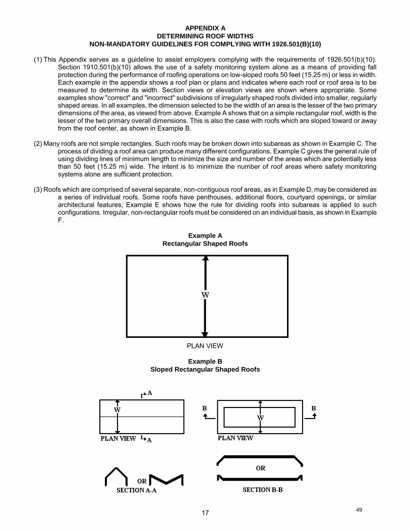
17
APPENDIX A
DETERMINING ROOF WIDTHS
NON-MANDATORY GUIDELINES FOR COMPLYING WITH 1926.501(B)(10) (1) This Appendix serves as a guideline to assist employers complying with the requirements of 1926.501(b)(10).
Section 1910.501(b)(10) allows the use of a safety monitoring system alone as a means of providing fall protection during the performance of roofing operations on low-sloped roofs 50 feet (15.25 m) or less in width. Each example in the appendix shows a roof plan or plans and indicates where each roof or roof area is to be measured to determine its width. Section views or elevation views are shown where appropriate. Some examples show "correct" and "incorrect" subdivisions of irregularly shaped roofs divided into smaller, regularly shaped areas. In all examples, the dimension selected to be the width of an area is the lesser of the two primary dimensions of the area, as viewed from above. Example A shows that on a simple rectangular roof, width is the lesser of the two primary overall dimensions. This is also the case with roofs which are sloped toward or away from the roof center, as shown in Example B.
(2) Many roofs are not simple rectangles. Such roofs may be broken down into subareas as shown in Example C. The
process of dividing a roof area can produce many different configurations. Example C gives the general rule of using dividing lines of minimum length to minimize the size and number of the areas which are potentially less than 50 feet (15.25 m) wide. The intent is to minimize the number of roof areas where safety monitoring systems alone are sufficient protection.
(3) Roofs which are comprised of several separate, non-contiguous roof areas, as in Example D, may be considered as
a series of individual roofs. Some roofs have penthouses, additional floors, courtyard openings, or similar architectural features; Example E shows how the rule for dividing roofs into subareas is applied to such configurations. Irregular, non-rectangular roofs must be considered on an individual basis, as shown in Example F.
Example A
Rectangular Shaped Roofs
PLAN VIEW
Example B
Sloped Rectangular Shaped Roofs
49
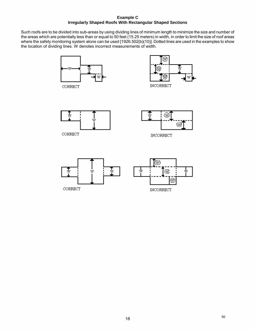
18
Example C
Irregularly Shaped Roofs With Rectangular Shaped Sections Such roofs are to be divided into sub-areas by using dividing lines of minimum length to minimize the size and number of the areas which are potentially less than or equal to 50 feet (15.25 meters) in width, in order to limit the size of roof areas where the safety monitoring system alone can be used [1926.502(b)(10)]. Dotted lines are used in the examples to show the location of dividing lines. W denotes incorrect measurements of width.
50
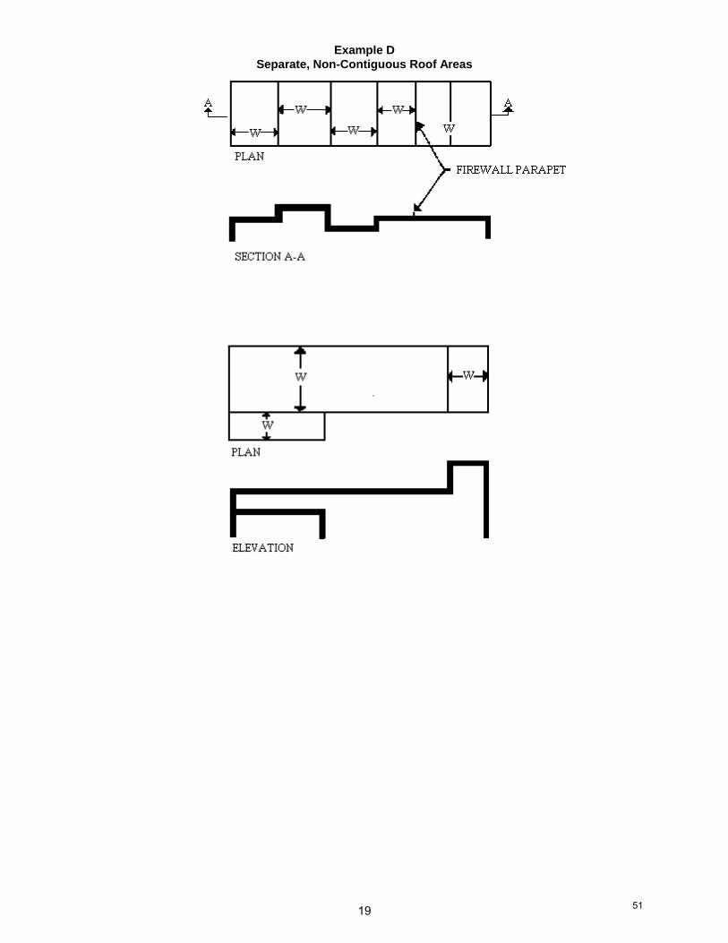
19
Example D
Separate, Non-Contiguous Roof Areas
51
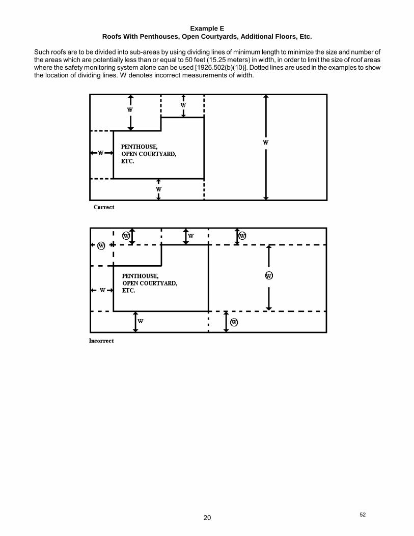
20
Example E
Roofs With Penthouses, Open Courtyards, Additional Floors, Etc.
Such roofs are to be divided into sub-areas by using dividing lines of minimum length to minimize the size and number ofthe areas which are potentially less than or equal to 50 feet (15.25 meters) in width, in order to limit the size of roof areaswhere the safety monitoring system alone can be used [1926.502(b)(10)]. Dotted lines are used in the examples to showthe location of dividing lines. W denotes incorrect measurements of width.
52
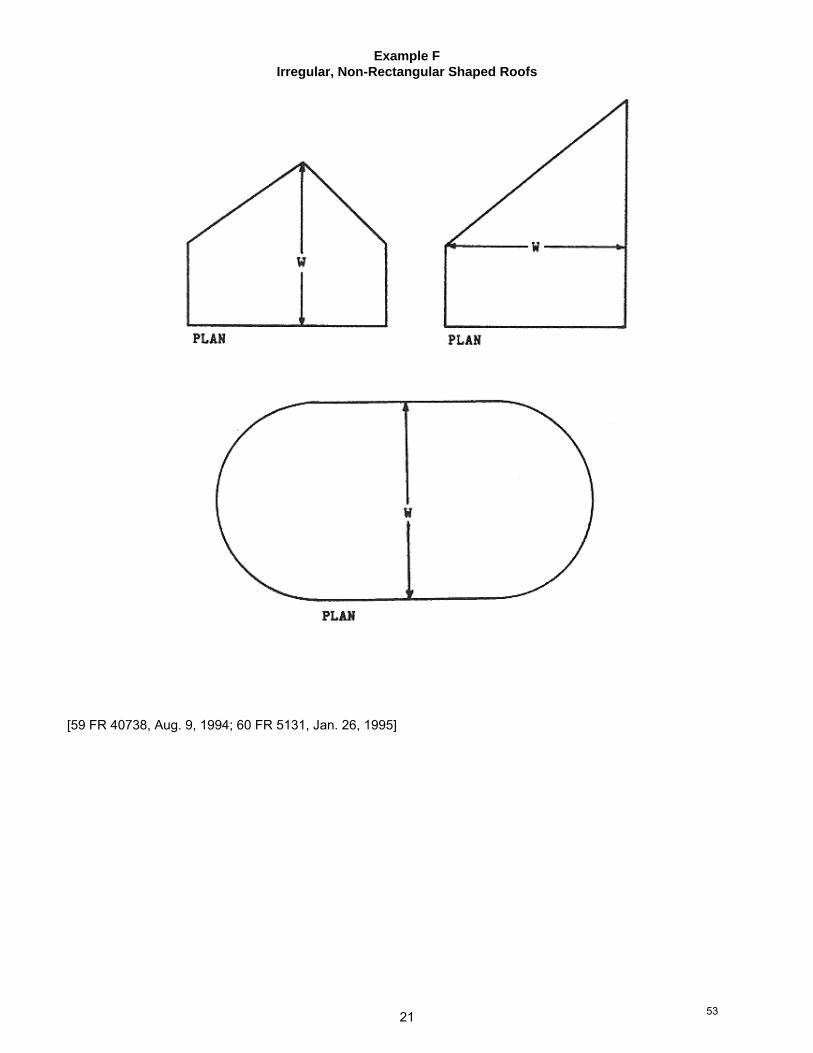
21
Example F
Irregular, Non-Rectangular Shaped Roofs
[59 FR 40738, Aug. 9, 1994; 60 FR 5131, Jan. 26, 1995]
53
22
APPENDIX B
GUARDRAIL SYSTEMS
NON-MANDATORY GUIDELINES FOR COMPLYING WITH 1926.502(B) The standard requires guardrail systems and components to be designed and built to meet the requirements of 1926.502(b)(3), (4), and (5). This Appendix serves as a non-mandatory guideline to assist employers in complying with these requirements. An employer may use these guidelines as a starting point for designing guardrail systems. However, the guidelines do not provide all the information necessary to build a complete system, and the employer is still responsible for designing and assembling these components in such a way that the completed system will meet the requirements of 1926.502(b)(3), (4), and (5). Components for which no specific guidelines are given in this Appendix (e.g., joints, base connections, components made with other materials, and components with other dimensions) must also be designed and constructed in such a way that the completed system meets the requirements of 1926.502.
(1) For wood railings:
Wood components shall be minimum 1500 lb-ft/in(2) fiber (stress grade) construction grade lumber; the posts shall be at least 2-inch by 4-inch (5 cm x 10 cm) lumber spaced not more than 8 feet (2.4 m) apart on centers; the top rail shall be at least 2-inch by 4-inch (5 cm x 10 cm) lumber, the intermediate rail shall be at least 1-inch by 6-inch (2.5 cm x 15 cm) lumber. All lumber dimensions are nominal sizes as provided by the American Softwood Lumber Standards, dated January 1970.
(2) For pipe railings:
posts, top rails, and intermediate railings shall be at least one and one-half inches nominal diameter (schedule 40 pipe) with posts spaced not more than 8 feet (2.4 m) apart on centers.
(3) For structural steel railings:
posts, top rails, and intermediate rails shall be at least 2-inch by 2-inch (5 cm x 10 cm) by 3/8-inch (1.1 cm) angles, with posts spaced not more than 8 feet (2.4 m) apart on centers.
[59 FR 40743, Aug. 9, 1994; 60 FR 5131, Jan. 26, 1995]
54
23
APPENDIX C
PERSONAL FALL ARREST SYSTEMS
NON-MANDATORY GUIDELINES FOR COMPLYING WITH 1926.502(D)
I. Test methods for personal fall arrest systems and positioning device systems
(a) "General."This appendix serves as a non-mandatory guideline to assist employers comply with the requirements in 1926.502(d).Paragraphs (b), (c), (d) and (e) of this Appendix describe test procedures which may be used to determine compliancewith the requirements in 1926.502 (d)(16). As noted in Appendix D of this subpart, the test methods listed here inAppendix C can also be used to assist employers comply with the requirements in 1926.502(e) (3) and (4) for positioningdevice systems.
(b) "General conditions for all tests in the Appendix to 1926.502(d)." (1) Lifelines, lanyards and deceleration devices should be attached to an anchorage and connected to the body-
belt or body harness in the same manner as they would be when used to protect employees.(2) The anchorage should be rigid, and should not have a deflection greater than 0.04 inches (1 mm) when a
force of 2,250 pounds (10 kN) is applied.(3) The frequency response of the load measuring instrumentation should be 500 Hz.(4) The test weight used in the strength and force tests should be a rigid, metal, cylindrical or torso-shaped object
with a girth of 38 inches plus or minus 4 inches (96 cm plus or minus 10 cm).(5) The lanyard or lifeline used to create the free fall distance should be supplied with the system, or in its
absence, the least elastic lanyard or lifeline available to be used with the system.(6) The test weight for each test should be hoisted to the required level and should be quickly released without
having any appreciable motion imparted to it.(7) The system's performance should be evaluated taking into account the range of environmental conditions for
which it is designed to be used. (8) Following the test, the system need not be capable of further operation.
(c) "Strength test." (1) During the testing of all systems, a test weight of 300 pounds plus or minus 5 pounds (135 kg plus or minus
2.5 kg) should be used. (See paragraph (b)(4) of this section.)(2) The test consists of dropping the test weight once. A new unused system should be used for each test.(3) For lanyard systems, the lanyard length should be 6 feet plus or minus 2 inches (1.83 m plus or minus 5 cm)
as measured from the fixed anchorage to the attachment on the body belt or body harness.(4) For rope-grab-type deceleration systems, the length of the lifeline above the centerline of the grabbing
mechanism to the lifeline's anchorage point should not exceed 2 feet (0.61 m).(5) For lanyard systems, for systems with deceleration devices which do not automatically limit free fall distance to
2 feet (0.61 m ) or less, and for systems with deceleration devices which have a connection distance in excessof 1 foot (0.3 m) (measured between the centerline of the lifeline and the attachment point to the body belt orharness), the test weight should be rigged to free fall a distance of 7.5 feet (2.3 m) from a point that is 1.5 feet(.46 m) above the anchorage point, to its hanging location (6 feet below the anchorage). The test weight shouldfall without interference, obstruction, or hitting the floor or ground during the test. In some cases a non-elasticwire lanyard of sufficient length may need to be added to the system (for test purposes) to create the necessaryfree fall distance.
(6) For deceleration device systems with integral lifelines or lanyards which automatically limit free fall distance to2 feet (0.61 m) or less, the test weight should be rigged to free fall a distance of 4 feet (1.22 m).
(7) Any weight which detaches from the belt or harness has failed the strength test.
(d) "Force test" (1) "General." The test consists of dropping the respective test weight once as specified in paragraph (d)(2)(i) or
(d)(3)(i) of this section. A new, unused system should be used for each test.(2) "For lanyard systems."
(i) A test weight of 220 pounds plus or minus 3 pounds (100 kg plus or minus 1.6 kg) should be used. (Seeparagraph (b)(4) of this appendix).
(ii) Lanyard length should be 6 feet plus or minus two inches (1.83 m plus or minus 5 cm) as measured fromthe fixed anchorage to the attachment on the body belt or body harness.
(iii) The test weight should fall free from the anchorage level to its hanging location (a total of 6 feet (1.83 m)free fall distance) without interference, obstruction, or hitting the floor or ground during the test.
55
24
(3) "For all other systems."(i) A test weight of 220 pounds plus or minus 3 pounds (100 kg plus or minus 1.6 kg) should be used. (See
paragraph (b)(4) of this appendix)(ii) The free fall distance to be used in the test should be the maximum fall distance physically permitted by the
system during normal use conditions, up to a maximum free fall distance for the test weight of 6 feet (1.83m), except as follows:(A) For deceleration systems which have a connection link or lanyard, the test weight should free fall a
distance equal to the connection distance (measured between the centerline of the lifeline and theattachment point to the body belt or harness).
(B) For deceleration device systems with integral lifelines or lanyards which automatically limit free falldistance to 2 feet (0.61 m) or less, the test weight should free fall a distance equal to that permitted bythe system in normal use. (For example, to test a system with a self-retracting lifeline or lanyard, thetest weight should be supported and the system allowed to retract the lifeline or lanyard as it would innormal use. The test weight would then be released and the force and deceleration distancemeasured).
(4) A system fails the force test if the recorded maximum arresting force exceeds 1,260 pounds (5.6 kN) whenusing a body belt, and/or exceeds 2,520 pounds (11.2 kN) when using a body harness.
(5) The maximum elongation and deceleration distance should be recorded during the force test.
(e) "Deceleration device tests."(1) "General." The device should be evaluated or tested under the environmental conditions, (such as rain, ice,
grease, dirt, type of lifeline, etc.), for which the device is designed.(2) "Rope-grab-type deceleration devices."
(i) Devices should be moved on a lifeline 1,000 times over the same length of line a distance of not less than1 foot (30.5 cm), and the mechanism should lock each time.
(ii) Unless the device is permanently marked to indicate the type(s) of lifeline which must be used, severaltypes (different diameters and different materials), of lifelines should be used to test the device.
(3) "Other self-activating-type deceleration devices." The locking mechanisms of other self-activating-typedeceleration devices designed for more than one arrest should lock each of 1,000 times as they would in normalservice.
II. Additional non-mandatory guidelines for personal fall arrest systems.The following information constitutes additional guidelines for use in complying with requirements for a personal fallarrest system.
(a) "Selection and use considerations."(1) The kind of personal fall arrest system selected should match the particular work situation, and any possible
free fall distance should be kept to a minimum. Consideration should be given to the particular workenvironment. For example, the presence of acids, dirt, moisture, oil, grease, etc., and their effect on the system,should be evaluated. Hot or cold environments may also have an adverse effect on the system. Wire ropeshould not be used where an electrical hazard is anticipated. As required by the standard, the employer mustplan to have means available to promptly rescue an employee should a fall occur, since the suspendedemployee may not be able to reach a work level independently.
(2) Where lanyards, connectors, and lifelines are subject to damage by work operations such as welding,chemical cleaning, and sandblasting, the component should be protected, or other securing systems should beused. The employer should fully evaluate the work conditions and environment (including seasonal weatherchanges) before selecting the appropriate personal fall protection system. Once in use, the system'seffectiveness should be monitored. In some cases, a program for cleaning and maintenance of the system maybe necessary.
(b) "Testing considerations."Before purchasing or putting into use a personal fall arrest system, an employer should obtain from the supplierinformation about the system based on its performance during testing so that the employer can know if the systemmeets this standard. Testing should be done using recognized test methods. This Appendix contains test methodsrecognized for evaluating the performance of fall arrest systems. Not all systems may need to be individually tested; theperformance of some systems may be based on data and calculations derived from testing of similar systems, providedthat enough information is available to demonstrate similarity of function and design.
56
25
(c) "Component compatibility considerations." Ideally, a personal fall arrest system is designed, tested, and supplied as a complete system. However, it is common practice for lanyards, connectors, lifelines, deceleration devices, body belts and body harnesses to be interchanged since some components wear out before others. The employer and employee should realize that not all components are interchangeable. For instance, a lanyard should not be connected between a body belt (or harness) and a deceleration device of the self-retracting type since this can result in additional free fall for which the system was not designed. Any substitution or change to a personal fall arrest system should be fully evaluated or tested by a competent person to determine that it meets the standard, before the modified system is put in use.
(d) "Employee training considerations." Thorough employee training in the selection and use of personal fall arrest systems is imperative. Employees must be trained in the safe use of the system. This should include the following: application limits; proper anchoring and tie-off techniques; estimation of free fall distance, including determination of deceleration distance, and total fall distance to prevent striking a lower level; methods of use; and inspection and storage of the system. Careless or improper use of the equipment can result in serious injury or death. Employers and employees should become familiar with the material in this Appendix, as well as manufacturer's recommendations, before a system is used. Of uppermost importance is the reduction in strength caused by certain tie-offs (such as using knots, tying around sharp edges, etc.) and maximum permitted free fall distance. Also, to be stressed are the importance of inspections prior to use, the limitations of the equipment, and unique conditions at the worksite which may be important in determining the type of system to use.
(e) "Instruction considerations." Employers should obtain comprehensive instructions from the supplier as to the system's proper use and application, including, where applicable:
(1) The force measured during the sample force test; (2) The maximum elongation measured for lanyards during the force test; (3) The deceleration distance measured for deceleration devices during the force test; (4) Caution statements on critical use limitations; (5) Application limits; (6) Proper hook-up, anchoring and tie-off techniques, including the proper dee-ring or other attachment point to
use on the body belt and harness for fall arrest; (7) Proper climbing techniques; (8) Methods of inspection, use, cleaning, and storage; and (9) Specific lifelines which may be used. This information should be provided to employees during training.
(f) "Rescue considerations." As required by 1926.502(d)(20), when personal fall arrest systems are used, the employer must assure that employees can be promptly rescued or can rescue themselves should a fall occur. The availability of rescue personnel, ladders or other rescue equipment should be evaluated. In some situations, equipment which allows employees to rescue themselves after the fall has been arrested may be desirable, such as devices which have descent capability. (g) "Inspection considerations." As required by 1926.502(d)(21), personal fall arrest systems must be regularly inspected. Any component with any significant defect, such as cuts, tears, abrasions, mold, or undue stretching; alterations or additions which might affect its efficiency; damage due to deterioration; contact with fire, acids, or other corrosives; distorted hooks or faulty hook springs; tongues unfitted to the shoulder of buckles; loose or damaged mountings; non-functioning parts; or wearing or internal deterioration in the ropes must be withdrawn from service immediately, and should be tagged or marked as unusable, or destroyed. (h) "Tie-off considerations."
(1) One of the most important aspects of personal fall protection systems is fully planning the system before it is put into use. Probably the most overlooked component is planning for suitable anchorage points. Such planning should ideally be done before the structure or building is constructed so that anchorage points can be incorporated during construction for use later for window cleaning or other building maintenance. If properly planned, these anchorage points may be used during construction, as well as afterwards. (i) Properly planned anchorages should be used if they are available. In some cases, anchorages must be
installed immediately prior to use. In such cases, a registered professional engineer with experience in designing fall protection systems, or another qualified person with appropriate education and experience should design an anchor point to be installed.
57
26
(ii) In other cases, the Agency recognizes that there will be a need to devise an anchor point from existing structures. Examples of what might be appropriate anchor points are steel members or I-beams if an acceptable strap is available for the connection (do not use a lanyard with a snaphook clipped onto itself); large eye-bolts made of an appropriate grade steel; guardrails or railings if they have been designed for use as an anchor point; or masonry or wood members only if the attachment point is substantial and precautions have been taken to assure that bolts or other connectors will not pull through. A qualified person should be used to evaluate the suitable of these "make shift" anchorages with a focus on proper strength.
(2) Employers and employees should at all times be aware that the strength of a personal fall arrest system is based on its being attached to an anchoring system which does not reduce the strength of the system (such as a properly dimensioned eye-bolt/snap-hook anchorage). Therefore, if a means of attachment is used that will reduce the strength of the system, that component should be replaced by a stronger one, but one that will also maintain the appropriate maximum arrest force characteristics.
(3) Tie-off using a knot in a rope lanyard or lifeline (at any location) can reduce the lifeline or lanyard strength by 50 percent or more. Therefore, a stronger lanyard or lifeline should be used to compensate for the weakening effect of the knot, or the lanyard length should be reduced (or the tie-off location raised) to minimize free fall distance, or the lanyard or lifeline should be replaced by one which has an appropriately incorporated connector to eliminate the need for a knot.
(4) Tie-off of a rope lanyard or lifeline around an "H" or "I" beam or similar support can reduce its strength as much as 70 percent due to the cutting action of the beam edges. Therefore, use should be made of a webbing lanyard or wire core lifeline around the beam; or the lanyard or lifeline should be protected from the edge; or free fall distance should be greatly minimized.
(5) Tie-off where the line passes over or around rough or sharp surfaces reduces strength drastically. Such a tie-off should be avoided or an alternative tie-off rigging should be used. Such alternatives may include use of a snap-hook/dee ring connection, wire rope tie-off, an effective padding of the surfaces, or an abrasion-resistance strap around or over the problem surface.
(6) Horizontal lifelines may, depending on their geometry and angle of sag, be subjected to greater loads than the impact load imposed by an attached component. When the angle of horizontal lifeline sag is less than 30 degrees, the impact force imparted to the lifeline by an attached lanyard is greatly amplified. For example, with a sag angle of 15 degrees, the force amplification is about 2:1 and at 5 degrees sag, it is about 6:1. Depending on the angle of sag, and the line's elasticity, the strength of the horizontal lifeline and the anchorages to which it is attached should be increased a number of times over that of the lanyard. Extreme care should be taken in considering a horizontal lifeline for multiple tie-offs. The reason for this is that in multiple tie-offs to a horizontal lifeline, if one employee falls, the movement of the falling employee and the horizontal lifeline during arrest of the fall may cause other employees to fall also. Horizontal lifeline and anchorage strength should be increased for each additional employee to be tied off. For these and other reasons, the design of systems using horizontal lifelines must only be done by qualified persons. Testing of installed lifelines and anchors prior to use is recommended.
(7) The strength of an eye-bolt is rated along the axis of the bolt and its strength is greatly reduced if the force is applied at an angle to this axis (in the direction of shear). Also, care should be exercised in selecting the proper diameter of the eye to avoid accidental disengagement of snap-hooks not designed to be compatible for the connection.
(8) Due to the significant reduction in the strength of the lifeline/lanyard (in some cases, as much as a 70 percent reduction), the sliding hitch knot (prusik) should not be used for lifeline/lanyard connections except in emergency situations where no other available system is practical. The "one-and-one" sliding hitch knot should never be used because it is unreliable in stopping a fall. The "two-and-two," or "three-and-three" knot (preferable) may be used in emergency situations; however, care should be taken to limit free fall distance to a minimum because of reduced lifeline/lanyard strength.
(i) "Vertical lifeline considerations." As required by the standard, each employee must have a separate lifeline [except employees engaged in constructing elevator shafts who are permitted to have two employees on one lifeline] when the lifeline is vertical. The reason for this is that in multiple tie-offs to a single lifeline, if one employee falls, the movement of the lifeline during the arrest of the fall may pull other employees' lanyards, causing them to fall as well.
58
27
(j) "Snap-hook considerations." (1) Although not required by this standard for all connections until January 1, 1998, locking snaphooks designed
for connection to suitable objects (of sufficient strength) are highly recommended in lieu of the nonlocking type. Locking snaphooks incorporate a positive locking mechanism in addition to the spring loaded keeper, which will not allow the keeper to open under moderate pressure without someone first releasing the mechanism. Such a feature, properly designed, effectively prevents roll-out from occurring.
(2) As required by 1926.502(d)(6), the following connections must be avoided (unless properly designed locking snaphooks are used) because they are conditions which can result in roll-out when a nonlocking snaphook is used: (i) Direct connection of a snaphook to a horizontal lifeline. (ii) Two (or more) snaphooks connected to one dee-ring. (iii) Two snaphooks connected to each other. (iv) A snaphook connected back on its integral lanyard. (v) A snaphook connected to a webbing loop or webbing lanyard. (vi) Improper dimensions of the dee-ring, rebar, or other connection point in relation to the snaphook
dimensions which would allow the snaphook keeper to be depressed by a turning motion of the snaphook. (k) "Free fall considerations." The employer and employee should at all times be aware that a system's maximum arresting force is evaluated under normal use conditions established by the manufacturer, and in no case using a free fall distance in excess of 6 feet (1.8 m). A few extra feet of free fall can significantly increase the arresting force on the employee, possibly to the point of causing injury. Because of this, the free fall distance should be kept at a minimum, and, as required by the standard, in no case greater than 6 feet (1.8 m). To help assure this, the tie-off attachment point to the lifeline or anchor should be located at or above the connection point of the fall arrest equipment to belt or harness. (Since otherwise additional free fall distance is added to the length of the connecting means (i.e. lanyard)). Attaching to the working surface will often result in a free fall greater than 6 feet (1.8 m). For instance, if a 6 foot (1.8 m) lanyard is used, the total free fall distance will be the distance from the working level to the body belt (or harness) attachment point plus the 6 feet (1.8 m) of lanyard length. Another important consideration is that the arresting force which the fall system must withstand also goes up with greater distances of free fall, possibly exceeding the strength of the system. (l) "Elongation and deceleration distance considerations." Other factors involved in a proper tie-off are elongation and deceleration distance. During the arresting of a fall, a lanyard will experience a length of stretching or elongation, whereas activation of a deceleration device will result in a certain stopping distance. These distances should be available with the lanyard or device's instructions and must be added to the free fall distance to arrive at the total fall distance before an employee is fully stopped. The additional stopping distance may be very significant if the lanyard or deceleration device is attached near or at the end of a long lifeline, which may itself add considerable distance due to its own elongation. As required by the standard, sufficient distance to allow for all of these factors must also be maintained between the employee and obstructions below, to prevent an injury due to impact before the system fully arrests the fall. In addition, a minimum of 12 feet (3.7 m) of lifeline should be allowed below the securing point of a rope grab type deceleration device, and the end terminated to prevent the device from sliding off the lifeline. Alternatively, the lifeline should extend to the ground or the next working level below. These measures are suggested to prevent the worker from inadvertently moving past the end of the lifeline and having the rope grab become disengaged from the lifeline. (m) "Obstruction considerations." The location of the tie-off should also consider the hazard of obstructions in the potential fall path of the employee. Tie-offs which minimize the possibilities of exaggerated swinging should be considered. In addition, when a body belt is used, the employee's body will go through a horizontal position to a jack-knifed position during the arrest of all falls. Thus, obstructions which might interfere with this motion should be avoided or a severe injury could occur. (n) "Other considerations." Because of the design of some personal fall arrest systems, additional considerations may be required for proper tie-off. For example, heavy deceleration devices of the self-retracting type should be secured overhead in order to avoid the weight of the device having to be supported by the employee. Also, if self-retracting equipment is connected to a horizontal lifeline, the sag in the lifeline should be minimized to prevent the device from sliding down the lifeline to a position which creates a swing hazard during fall arrest. In all cases, manufacturer's instructions should be followed. [59 FR 40743, Aug. 9, 1994; 60 FR 5131, Jan. 26, 1995]
59
28
APPENDIX D
POSITIONING DEVICE SYSTEMS
NON-MANDATORY GUIDELINES FOR COMPLYING WITH 1926.502(E) I. Testing Methods For Positioning Device Systems. This appendix serves as a non-mandatory guideline to assist employers comply with the requirements for positioning device systems in 1926.502(e). Paragraphs (b), (c), (d) and (e) of Appendix C of subpart M relating to 1926.502(d) - Personal Fall Arrest Systems - set forth test procedures which may be used, along with the procedures listed below, to determine compliance with the requirements for positioning device systems in 1926.502(e)(3) and (4) of Subpart M. (a) "General."
(1) Single strap positioning devices shall have one end attached to a fixed anchorage and the other end connected to a body belt or harness in the same manner as they would be used to protect employees. Double strap positioning devices, similar to window cleaner's belts, shall have one end of the strap attached to a fixed anchorage and the other end shall hang free. The body belt or harness shall be attached to the strap in the same manner as it would be used to protect employees. The two strap ends shall be adjusted to their maximum span.
(2) The fixed anchorage shall be rigid, and shall not have a deflection greater than .04 inches (1 mm) when a force of 2,250 pounds (10 kN) is applied.
(3) During the testing of all systems, a test weight of 250 pounds plus or minus 3 pounds (113 kg plus or minus 1.6 kg) shall be used. The weight shall be a rigid object with a girth of 38 inches plus or minus 4 inches (96 cm plus or minus 10 cm).
(4) Each test shall consist of dropping the specified weight one time without failure of the system being tested. A new system shall be used for each test.
(5) The test weight for each test shall be hoisted exactly 4 feet (1.2 m above its "at rest" position), and shall be dropped so as to permit a vertical free fall of 4 feet (1.2 m).
(6) The test is failed whenever any breakage or slippage occurs which permits the weight to fall free of the system.
(7) Following the test, the system need not be capable of further operation; however, all such incapacities shall be readily apparent.
II. Inspection Considerations. As required in 1926.502 (e)(5), positioning device systems must be regularly inspected. Any component with any significant defect, such as cuts, tears, abrasions, mold, or undue stretching; alterations or additions which might affect its efficiency; damage due to deterioration; contact with fire, acids, or other corrosives; distorted hooks or faulty hook springs; tongues unfitted to the shoulder of buckles; loose or damaged mountings; non-functioning parts; or wearing or internal deterioration in the ropes must be withdrawn from service immediately, and should be tagged or marked as unusable, or destroyed. [59 FR 40746, Aug. 9, 1994; 60 FR 5131, Jan. 26, 1995]
60
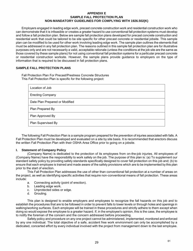
29
APPENDIX E
SAMPLE FALL PROTECTION PLAN
NON-MANDATORY GUIDELINES FOR COMPLYING WITH 1926.502(K)
Employers engaged in leading edge work, precast concrete construction work and residential construction work who can demonstrate that it is infeasible or creates a greater hazard to use conventional fall protection systems must develop and follow a fall protection plan. Below are sample fall protection plans developed for precast concrete construction and residential work that could be tailored to be site specific for other precast concrete or residential jobsite. This sample plan can be modified to be used for other work involving leading edge work. The sample plan outlines the elements that must be addressed in any fall protection plan. The reasons outlined in this sample fall protection plan are for illustrative purposes only and are not necessarily a valid, acceptable rationale (unless the conditions at the job site are the same as those covered by these sample plans) for not using conventional fall protection systems for a particular precast concrete or residential construction worksite. However, the sample plans provide guidance to employers on the type of information that is required to be discussed in fall protection plans.
SAMPLE FALL PROTECTION PLANS
Fall Protection Plan For Precast/Prestress Concrete Structures This Fall Protection Plan is specific for the following project:
Location of Job
Erecting Company
Date Plan Prepared or Modified
Plan Prepared By
Plan Approved By
Plan Supervised By
The following Fall Protection Plan is a sample program prepared for the prevention of injuries associated with falls. A
Fall Protection Plan must be developed and evaluated on a site by site basis. It is recommended that erectors discuss the written Fall Protection Plan with their OSHA Area Office prior to going on a jobsite.
I. Statement of Company Policy
(Company Name) is dedicated to the protection of its employees from on-the-job injuries. All employees of (Company Name) have the responsibility to work safely on the job. The purpose of this plan is: (a) To supplement our standard safety policy by providing safety standards specifically designed to cover fall protection on this job and; (b) to ensure that each employee is trained and made aware of the safety provisions which are to be implemented by this plan prior to the start of erection.
This Fall Protection Plan addresses the use of other than conventional fall protection at a number of areas on the project, as well as identifying specific activities that require non-conventional means of fall protection. These areas include:
a. Connecting activity (point of erection). b. Leading edge work. c. Unprotected sides or edge. d. Grouting.
This plan is designed to enable employers and employees to recognize the fall hazards on this job and to
establish the procedures that are to be followed in order to prevent falls to lower levels or through holes and openings in walking/working surfaces. Each employee will be trained in these procedures and strictly adhere to them except when doing so would expose the employee to a greater hazard. If, in the employee's opinion, this is the case, the employee is to notify the foreman of the concern and the concern addressed before proceeding.
Safety policy and procedure on any one project cannot be administered, implemented, monitored and enforced by any one individual. The total objective of a safe, accident free work environment can only be accomplished by a dedicated, concerted effort by every individual involved with the project from management down to the last employee.
61
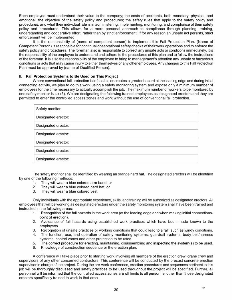
30
Each employee must understand their value to the company; the costs of accidents, both monetary, physical, andemotional; the objective of the safety policy and procedures; the safety rules that apply to the safety policy andprocedures; and what their individual role is in administering, implementing, monitoring, and compliance of their safetypolicy and procedures. This allows for a more personal approach to compliance through planning, training,understanding and cooperative effort, rather than by strict enforcement. If for any reason an unsafe act persists, strictenforcement will be implemented.
It is the responsibility of (name of competent person) to implement this Fall Protection Plan. (Name ofCompetent Person) is responsible for continual observational safety checks of their work operations and to enforce thesafety policy and procedures. The foreman also is responsible to correct any unsafe acts or conditions immediately. It isthe responsibility of the employee to understand and adhere to the procedures of this plan and to follow the instructionsof the foreman. It is also the responsibility of the employee to bring to management's attention any unsafe or hazardousconditions or acts that may cause injury to either themselves or any other employees. Any changes to this Fall ProtectionPlan must be approved by (name of Qualified Person).
II. Fall Protection Systems to Be Used on This ProjectWhere conventional fall protection is infeasible or creates a greater hazard at the leading edge and during initial
connecting activity, we plan to do this work using a safety monitoring system and expose only a minimum number ofemployees for the time necessary to actually accomplish the job. The maximum number of workers to be monitored byone safety monitor is six (6). We are designating the following trained employees as designated erectors and they arepermitted to enter the controlled access zones and work without the use of conventional fall protection.
Safety monitor:
Designated erector:
Designated erector:
Designated erector:
Designated erector:
Designated erector:
Designated erector:
The safety monitor shall be identified by wearing an orange hard hat. The designated erectors will be identifiedby one of the following methods:
1. They will wear a blue colored arm band, or2. They will wear a blue colored hard hat, or3. They will wear a blue colored vest.
Only individuals with the appropriate experience, skills, and training will be authorized as designated erectors. Allemployees that will be working as designated erectors under the safety monitoring system shall have been trained andinstructed in the following areas:
1. Recognition of the fall hazards in the work area (at the leading edge and when making initial connections-point of erection).
2. Avoidance of fall hazards using established work practices which have been made known to theemployees.
3. Recognition of unsafe practices or working conditions that could lead to a fall, such as windy conditions.4. The function, use, and operation of safety monitoring systems, guardrail systems, body belt/harness
systems, control zones and other protection to be used.5. The correct procedure for erecting, maintaining, disassembling and inspecting the system(s) to be used.6. Knowledge of construction sequence or the erection plan.
A conference will take place prior to starting work involving all members of the erection crew, crane crew andsupervisors of any other concerned contractors. This conference will be conducted by the precast concrete erectionsupervisor in charge of the project. During the pre-work conference, erection procedures and sequences pertinent to thisjob will be thoroughly discussed and safety practices to be used throughout the project will be specified. Further, allpersonnel will be informed that the controlled access zones are off limits to all personnel other than those designatederectors specifically trained to work in that area.
62
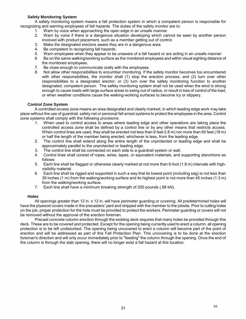
31
Safety Monitoring System A safety monitoring system means a fall protection system in which a competent person is responsible for
recognizing and warning employees of fall hazards. The duties of the safety monitor are to: 1. Warn by voice when approaching the open edge in an unsafe manner. 2. Warn by voice if there is a dangerous situation developing which cannot be seen by another person
involved with product placement, such as a member getting out of control. 3. Make the designated erectors aware they are in a dangerous area. 4. Be competent in recognizing fall hazards. 5. Warn employees when they appear to be unaware of a fall hazard or are acting in an unsafe manner. 6. Be on the same walking/working surface as the monitored employees and within visual sighting distance of
the monitored employees. 7. Be close enough to communicate orally with the employees. 8. Not allow other responsibilities to encumber monitoring. If the safety monitor becomes too encumbered
with other responsibilities, the monitor shall (1) stop the erection process; and (2) turn over other responsibilities to a designated erector; or (3) turn over the safety monitoring function to another designated, competent person. The safety monitoring system shall not be used when the wind is strong enough to cause loads with large surface areas to swing out of radius, or result in loss of control of the load, or when weather conditions cause the walking-working surfaces to become icy or slippery.
Control Zone System
A controlled access zone means an area designated and clearly marked, in which leading edge work may take place without the use of guardrail, safety net or personal fall arrest systems to protect the employees in the area. Control zone systems shall comply with the following provisions:
1. When used to control access to areas where leading edge and other operations are taking place the controlled access zone shall be defined by a control line or by any other means that restricts access. When control lines are used, they shall be erected not less than 6 feet (l.8 m) nor more than 60 feet (18 m) or half the length of the member being erected, whichever is less, from the leading edge.
2. The control line shall extend along the entire length of the unprotected or leading edge and shall be approximately parallel to the unprotected or leading edge.
3. The control line shall be connected on each side to a guardrail system or wall. 4. Control lines shall consist of ropes, wires, tapes, or equivalent materials, and supporting stanchions as
follows: 5. Each line shall be flagged or otherwise clearly marked at not more than 6-foot (1.8 m) intervals with high-
visibility material. 6. Each line shall be rigged and supported in such a way that its lowest point (including sag) is not less than
39 inches (1 m) from the walking/working surface and its highest point is not more than 45 inches (1.3 m) from the walking/working surface.
7. Each line shall have a minimum breaking strength of 200 pounds (.88 kN).
Holes All openings greater than 12 in. x 12 in. will have perimeter guarding or covering. All predetermined holes will
have the plywood covers made in the precasters' yard and shipped with the member to the jobsite. Prior to cutting holes on the job, proper protection for the hole must be provided to protect the workers. Perimeter guarding or covers will not be removed without the approval of the erection foreman.
Precast concrete column erection through the existing deck requires that many holes be provided through this deck. These are to be covered and protected. Except for the opening being currently used to erect a column, all opening protection is to be left undisturbed. The opening being uncovered to erect a column will become part of the point of erection and will be addressed as part of this Fall Protection Plan. This uncovering is to be done at the erection foreman's direction and will only occur immediately prior to "feeding" the column through the opening. Once the end of the column is through the slab opening, there will no longer exist a fall hazard at this location.
63
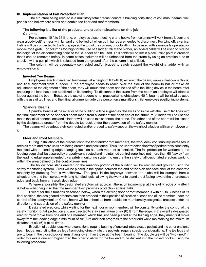
32
III. Implementation of Fall Protection Plan The structure being erected is a multistory total precast concrete building consisting of columns, beams, wall
panels and hollow core slabs and double tee floor and roof members. The following is a list of the products and erection situations on this job:
Columns For columns 10 ft to 36 ft long, employees disconnecting crane hooks from columns will work from a ladder and
wear a body belt/harness with lanyard and be tied off when both hands are needed to disconnect. For tying off, a vertical lifeline will be connected to the lifting eye at the top of the column, prior to lifting, to be used with a manually operated or mobile rope grab. For columns too high for the use of a ladder, 36 ft and higher, an added cable will be used to reduce the height of the disconnecting point so that a ladder can be used. This cable will be left in place until a point in erection that it can be removed safely. In some cases, columns will be unhooked from the crane by using an erection tube or shackle with a pull pin which is released from the ground after the column is stabilized.
The column will be adequately connected and/or braced to safely support the weight of a ladder with an employee on it.
Inverted Tee Beams Employees erecting inverted tee beams, at a height of 6 to 40 ft, will erect the beam, make initial connections,
and final alignment from a ladder. If the employee needs to reach over the side of the beam to bar or make an adjustment to the alignment of the beam, they will mount the beam and be tied off to the lifting device in the beam after ensuring the load has been stabilized on its bearing. To disconnect the crane from the beam an employee will stand a ladder against the beam. Because the use of ladders is not practical at heights above 40 ft, beams will be initially placed with the use of tag lines and their final alignment made by a person on a manlift or similar employee positioning systems.
Spandrel Beams
Spandrel beams at the exterior of the building will be aligned as closely as possible with the use of tag lines with the final placement of the spandrel beam made from a ladder at the open end of the structure. A ladder will be used to make the initial connections and a ladder will be used to disconnect the crane. The other end of the beam will be placed by the designated erector from the double tee deck under the observation of the safety monitor.
The beams will be adequately connected and/or braced to safely support the weight of a ladder with an employee on it.
Floor and Roof Members
During installation of the precast concrete floor and/or roof members, the work deck continuously increases in area as more and more units are being erected and positioned. Thus, the unprotected floor/roof perimeter is constantly modified with the leading edge changing location as each member is installed. The fall protection for workers at the leading edge shall be assured by properly constructed and maintained control zone lines not more than 60 ft away from the leading edge supplemented by a safety monitoring system to ensure the safety of all designated erectors working within the area defined by the control zone lines.
The hollow core slabs erected on the masonry portion of the building will be erected and grouted using the safety monitoring system. Grout will be placed in the space between the end of the slab and face shell of the concrete masonry by dumping from a wheelbarrow. The grout in the keyways between the slabs will be dumped from a wheelbarrow and then spread with long handled tools, allowing the worker to stand erect facing toward the unprotected edge and back from any work deck edge.
Whenever possible, the designated erectors will approach the incoming member at the leading edge only after it is below waist height so that the member itself provides protection against falls.
Except for the situations described below, when the arriving floor or roof member is within 2 to 3 inches of its final position, the designated erectors can then proceed to their position of erection at each end of the member under the control of the safety monitor. Crane hooks will be unhooked from double tee members by designated erectors under the direction and supervision of the safety monitor.
Designated erectors, while waiting for the next floor or roof member, will be constantly under the control of the safety monitor for fall protection and are directed to stay a minimum of six (6) ft from the edge. In the event a designated erector must move from one end of a member, which has just been placed at the leading edge, they must first move away from the leading edge a minimum of six (6) ft and then progress to the other end while maintaining the minimum distance of six (6) ft at all times.
Erection of double tees, where conditions require bearing of one end into a closed pocket and the other end on a beam ledge, restricting the tee legs from going directly into the pockets, require special considerations. The tee legs that are to bear in the closed pocket must hang lower than those at the beam bearing. The double tee will be "two-lined" in order to elevate one end higher than the other to allow for the low end to be ducked into the closed pocket using the following procedure.
64
33
The double tee will be rigged with a standard four-way spreader off of the main load line. An additional chokerwill be attached to the married point of the two-legged spreader at the end of the tee that is to be elevated. The doubletee will be hoisted with the main load line and swung into a position as close as possible to the tee's final bearingelevation. When the tee is in this position and stabilized, the whip line load block will be lowered to just above the teedeck. At this time, two erectors will walk out on the suspended tee deck at midspan of the tee member and pull the loadblock to the end of the tee to be elevated and attach the additional choker to the load block. The possibility ofentanglement with the crane lines and other obstacles during this two lining process while raising and lowering the craneblock on that second line could be hazardous to an encumbered employee. Therefore, the designated erectors will nottie off during any part of this process. While the designated erectors are on the double tee, the safety monitoring systemwill be used. After attaching the choker, the two erectors then step back on the previously erected tee deck and signalthe crane operator to hoist the load with the whip line to the elevation that will allow for enough clearance to let the lowend tee legs slide into the pockets when the main load line is lowered. The erector, who is handling the lowered end ofthe tee at the closed pocket bearing, will step out on the suspended tee. An erection bar will then be placed between theend of the tee leg and the inside face of the pocketed spandrel member. The tee is barred away from the pocketedmember to reduce the friction and lateral force against the pocketed member. As the tee is being lowered, the othererector remains on the tee which was previously erected to handle the other end. At this point the tee is slowly loweredby the crane to a point where the tee legs can freely slide into the pockets. The erector working the lowered end of thetee must keep pressure on the bar between the tee and the face of the pocketed spandrel member to very gradually letthe tee legs slide into the pocket to its proper bearing dimension. The tee is then slowly lowered into its final erectedposition.
The designated erector should be allowed onto the suspended double tee, otherwise there is no control over thehorizontal movement of the double tee and this movement could knock the spandrel off of its bearing or the column outof plumb. The control necessary to prevent hitting the spandrel can only be done safely from the top of the double teebeing erected.
Loadbearing Wall Panels: The erection of the loadbearing wall panels on the elevated decks requires the use ofa safety monitor and a controlled access zone that is a minimum of 25 ft and a maximum of 1/2 the length of the wallpanels away from the unprotected edge, so that designated erectors can move freely and unencumbered when receivingthe panels. Bracing, if required for stability, will be installed by ladder. After the braces are secured, the crane will bedisconnected from the wall by using a ladder. The wall to wall connections will also be performed from a ladder.
Non-Loadbearing Panels (Cladding): The locating of survey lines, panel layout and other installationprerequisites (prewelding, etc.) for non-loadbearing panels (cladding) will not commence until floor perimeter and flooropenings have been protected. In some areas, it is necessary because of panel configuration to remove the perimeterprotection as the cladding is being installed. Removal of perimeter protection will be performed on a bay to bay basis,just ahead of cladding erection to minimize temporarily unprotected floor edges. Those workers within 6 ft of the edge,receiving and positioning the cladding when the perimeter protection is removed shall be tied off.
Detailing Employees exposed to falls of six (6) feet or more to lower levels, who are not actively engaged in leading edge
work or connecting activity, such as welding, bolting, cutting, bracing, guying, patching, painting or other operations, andwho are working less than six (6) ft from an unprotected edge will be tied off at all times or guardrails will be installed.Employees engaged in these activities but who are more than six (6) ft from an unprotected edge as defined by thecontrol zone lines, do not require fall protection but a warning line or control lines must be erected to remind employeesthey are approaching an area where fall protection is required.
IV. Conventional Fall Protection Considered for the Point of Erection or Leading Edge Erection Operations
A. Personal Fall Arrest SystemsIn this particular erection sequence and procedure, personal fall arrest systems requiring body belt/harness
systems, lifelines and lanyards will not reduce possible hazards to workers and will create offsetting hazards during theirusage at the leading edge of precast/prestressed concrete construction.
Leading edge erection and initial connections are conducted by employees who are specifically trained to do thistype of work and are trained to recognize the fall hazards. The nature of such work normally exposes the employee tothe fall hazard for a short period of time and installation of fall protection systems for a short duration is not feasiblebecause it exposes the installers of the system to the same fall hazard, but for a longer period of time.
1. It is necessary that the employee be able to move freely without encumbrance in order to guide thesections of precast concrete into their final position without having lifelines attached which will restrict theemployee's ability to move about at the point of erection.
2. A typical procedure requires 2 or more workers to maneuver around each other as a concrete member ispositioned to fit into the structure. If they are each attached to a lifeline, part of their attention must bediverted from their main task of positioning a member weighing several tons to the task of avoidingentanglements of their lifelines or avoiding tripping over lanyards. Therefore, if these workers are attachedto lanyards, more fall potential would result than from not using such a device.
65
34
In this specific erection sequence and procedure, retractable lifelines do not solve the problem of two workersbecoming tangled. In fact, such a tangle could prevent the lifeline from retracting as the worker moved, thus potentiallyexposing the worker to a fall greater than 6 ft. Also, a worker crossing over the lifeline of another worker can create ahazard because the movement of one person can unbalance the other. In the event of a fall by one person there is alikelihood that the other person will be caused to fall as well. In addition, if contamination such as grout (during hollowcore grouting) enters the retractable housing it can cause excessive wear and damage to the device and could clog theretracting mechanism as the lanyard is dragged across the deck. Obstructing the cable orifice can defeat the device'sshock absorbing function, produce cable slack and damage, and adversely affect cable extraction and retraction.
3. Employees tied to a lifeline can be trapped and crushed by moving structural members if the employeebecomes restrained by the lanyard or retractable lifeline and cannot get out of the path of the moving load.The sudden movement of a precast concrete member being raised by a crane can be caused by a numberof factors. When this happens, a connector may immediately have to move a considerable distance to avoidinjury. If a tied off body belt/harness is being used, the connector could be trapped. Therefore, there is agreater risk of injury if the connector is tied to the structure for this specific erection sequence andprocedure.
When necessary to move away from a retractable device, the worker cannot move at a rate greater than thedevice locking speed typically 3.5 to 4.5 ft/sec. When moving toward the device it is necessary to move at a rate whichdoes not permit cable slack to build up. This slack may cause cable retraction acceleration and cause a worker to losetheir balance by applying a higher than normal jerking force on the body when the cable suddenly becomes taut afterbuilding up momentum. This slack can also cause damage to the internal spring-loaded drum, uneven coiling of cableon the drum, and possible cable damage.
The factors causing sudden movements for this location include:(a) Cranes
(1) Operator error.(2) Site conditions (soft or unstable ground).(3) Mechanical failure.(4) Structural failure.(5) Rigging failure.(6) Crane signal/radio communication failure.
(b) Weather Conditions(1) Wind (strong wind/sudden gusting) - particularly a problem with the large surface areas of precast
concrete members.(2) Snow/rain (visibility).(3) Fog (visibility).(4) Cold - causing slowed reactions or mechanical problems.
(c) Structure/Product Conditions.(1) Lifting Eye failure.(2) Bearing failure or slippage.(3) Structure shifting.(4) Bracing failure.(5) Product failure.
(d) Human Error.(1) Incorrect tag line procedure.(2) Tag line hang-up.(3) Incorrect or misunderstood crane signals.(4) Misjudged elevation of member.(5) Misjudged speed of member.(6) Misjudged angle of member.
4. Anchorages or special attachment points could be cast into the precast concrete members if sufficientpreplanning and consideration of erectors' position is done before the members are cast. Any hole or otherattachment must be approved by the engineer who designed the member. It is possible that some designrestrictions will not allow a member to be weakened by an additional hole; however, it is anticipated thatsuch situations would be the exception, not the rule. Attachment points, other than on the deck surface, willrequire removal and/or patching. In order to remove and/or patch these points, requires the employee to beexposed to an additional fall hazard at an unprotected perimeter. The fact that attachment points could beavailable anywhere on the structure does not eliminate the hazards of using these points for tying off asdiscussed above. A logical point for tying off on double tees would be using the lifting loops, except that theymust be cut off to eliminate a tripping hazard at an appropriate time.
66
35
5. Providing attachment at a point above the walking/working surface would also create fall exposures foremployees installing their devices. Final positioning of a precast concrete member requires it to be movedin such a way that it must pass through the area that would be occupied by the lifeline and the lanyardsattached to the point above. Resulting entanglements of lifelines and lanyards on a moving member couldpull employees from the work surface. Also, the structure is being created and, in most cases, there is nostructure above the members being placed.(a) Temporary structural supports, installed to provide attaching points for lifelines limit the space which is
essential for orderly positioning, alignment and placement of the precast concrete members. To keepthe lanyards a reasonable and manageable length, lifeline supports would necessarily need to be inproximity to the positioning process. A sudden shift of the precast concrete member being positionedbecause of wind pressure or crane movement could make it strike the temporary supporting structure,moving it suddenly and causing tied off employees to fall.
(b) The time in manhours which would be expended in placing and maintaining temporary structuralsupports for lifeline attaching points could exceed the expended manhours involved in placing theprecast concrete members. No protection could be provided for the employees erecting the temporarystructural supports and these supports would have to be moved for each successive step in theconstruction process, thus greatly increasing the employee's exposure to the fall hazard.
(c) The use of a cable strung horizontally between two columns to provide tie off lines for erecting orwalking a beam for connecting work is not feasible and creates a greater hazard on this multi-storybuilding for the following reasons:(1) If a connector is to use such a line, it must be installed between the two columns. To perform this
installation requires an erector to have more fall exposure time attaching the cable to the columnsthan would be spent to make the beam to column connection itself.
(2) If such a line is to be installed so that an erector can walk along a beam, it must be overhead orbelow him. For example, if a connector must walk along a 24 in. wide beam, the presence of a linenext to the connector at waist level, attached directly to the columns, would prevent the connectorfrom centering their weight over the beam and balancing themselves. Installing the line above theconnector might be possible on the first level of a two-story column; however, the column mayextend only a few feet above the floor level at the second level or be flush with the floor level.Attaching the line to the side of the beam could be a solution; however, it would require theconnector to attach the lanyard below foot level which would most likely extend a fall farther than 6ft.
(3) When lines are strung over every beam, it becomes more and more difficult for the crane operatorto lower a precast concrete member into position without the member becoming fouled. Should themember become entangled, it could easily dislodge the line from a column. If a worker is tied to itat the time, a fall could be caused.
6. The ANSI A10.14-1991 American National Standard for Construction and Demolition Operations -Requirements for Safety Belts, Harnesses, Lanyards and Lifelines for Construction and Demolition Use,states that the anchor point of a lanyard or deceleration device should, if possible, be located above thewearer's belt or harness attachment. ANSI A10.14 also states that a suitable anchorage point is one whichis located as high as possible to prevent contact with an obstruction below should the worker fall. Mostmanufacturers also warn in the user's handbook that the safety block/retractable lifeline must be positionedabove the D-ring (above the work space of the intended user) and OSHA recommends that fall arrest andrestraint equipment be used in accordance with the manufacturer's instructions.
Attachment of a retractable device to a horizontal cable near floor level or using the inserts in the floor or roofmembers may result in increased free fall due to the dorsal D-ring of the full-body harness riding higher than theattachment point of the snaphook to the cable or insert (e.g., 6 foot tall worker with a dorsal D-ring at 5 feet above thefloor or surface, reduces the working length to only one foot, by placing the anchorage five feet away from the fallhazard). In addition, impact loads may exceed maximum fall arrest forces (MAF) because the fall arrest D-ring would be4 to 5 feet higher than the safety block/retractable lifeline anchored to the walking-working surface; and the potential forswing hazards is increased. Manufacturers also require that workers not work at a level where the point of snaphookattachment to the body harness is above the device because this will increase the free fall distance and the decelerationdistance and will cause higher forces on the body in the event of an accidental fall.
Manufacturers recommend an anchorage for the retractable lifeline which is immovably fixed in space and isindependent of the user's support systems. A moveable anchorage is one which can be moved around (such asequipment or wheeled vehicles) or which can deflect substantially under shock loading (such as a horizontal cable orvery flexible beam). In the case of a very flexible anchorage, a shock load applied to the anchorage during fall arrest cancause oscillation of the flexible anchorage such that the retractable brake mechanism may undergo one or more cyclesof locking/unlocking/locking (ratchet effect) until the anchorage deflection is dampened. Therefore, use of a moveableanchorage involves critical engineering and safety factors and should only be considered after fixed anchorage has beendetermined to be not feasible.
67
36
Horizontal cables used as an anchorage present an additional hazard due to amplification of the horizontal component of maximum arrest force (of a fall) transmitted to the points where the horizontal cable is attached to the structure. This amplification is due to the angle of sag of a horizontal cable and is most severe for small angles of sag. For a cable sag angle of 2 degrees the horizontal force on the points of cable attachment can be amplified by a factor of 15.
It is also necessary to install the retractable device vertically overhead to minimize swing falls. If an object is in the worker's swing path (or that of the cable) hazardous situations exist:
(1) due to the swing, horizontal speed of the user may be high enough to cause injury when an obstacle in the swing fall path is struck by either the user or the cable;
(2) the total vertical fall distance of the user may be much greater than if the user had fallen only vertically without a swing fall path.
With retractable lines, overconfidence may cause the worker to engage in inappropriate behavior, such as approaching the perimeter of a floor or roof at a distance appreciably greater than the shortest distance between the anchorage point and the leading edge. Though the retractable lifeline may arrest a worker's fall before he or she has fallen a few feet, the lifeline may drag along the edge of the floor or beam and swing the worker like a pendulum until the line has moved to a position where the distance between the anchorage point and floor edge is the shortest distance between those two points. Accompanying this pendulum swing is a lowering of the worker, with the attendant danger that he or she may violently impact the floor or some obstruction below.
The risk of a cable breaking is increased if a lifeline is dragged sideways across the rough surface or edge of a concrete member at the same moment that the lifeline is being subjected to a maximum impact loading during a fall. The typical 3/16 in. cable in a retractable lifeline has a breaking strength of from 3000 to 3700 lbs.
7. The competent person, who can take into account the specialized operations being performed on this project, should determine when and where a designated erector cannot use a personal fall arrest system.
B. Safety Net Systems The nature of this particular precast concrete erection worksite precludes the safe use of safety nets where point of
erection or leading edge work must take place. 1. To install safety nets in the interior high bay of the single story portion of the building poses rigging
attachment problems. Structural members do not exist to which supporting devices for nets can be attached in the area where protection is required. As the erection operation advances, the location of point of erection or leading edge work changes constantly as each member is attached to the structure. Due to this constant change it is not feasible to set net sections and build separate structures to support the nets.
2. The nature of the erection process for the precast concrete members is such that an installed net would protect workers as they position and secure only one structural member. After each member is stabilized the net would have to be moved to a new location (this could mean a move of 8 to 10 ft or the possibility of a move to a different level or area of the structure) to protect workers placing the next piece in the construction sequence. The result would be the installation and dismantling of safety nets repeatedly throughout the normal work day. As the time necessary to install a net, test, and remove it is significantly greater than the time necessary to position and secure a precast concrete member, the exposure time for the worker installing the safety net would be far longer than for the workers whom the net is intended to protect. The time exposure repeats itself each time the nets and supporting hardware must be moved laterally or upward to provide protection at the point of erection or leading edge.
3. Strict interpretation of 1926.502(c) requires that operations shall not be undertaken until the net is in place and has been tested. With the point of erection constantly changing, the time necessary to install and test a safety net significantly exceeds the time necessary to position and secure the concrete member.
4. Use of safety nets on exposed perimeter wall openings and opensided floors, causes attachment points to be left in architectural concrete which must be patched and filled with matching material after the net supporting hardware is removed. In order to patch these openings, additional numbers of employees must be suspended by swing stages, boatswain chairs or other devices, thereby increasing the amount of fall exposure time to employees.
5. Installed safety nets pose an additional hazard at the perimeter of the erected structure where limited space is available in which members can be turned after being lifted from the ground by the crane. There would be a high probability that the member being lifted could become entangled in net hardware, cables, etc.
6. The use of safety nets where structural wall panels are being erected would prevent movement of panels to point of installation. To be effective, nets would necessarily have to provide protection across the area where structural supporting wall panels would be set and plumbed before roof units could be placed.
7. Use of a tower crane for the erection of the high rise portion of the structure poses a particular hazard in that the crane operator cannot see or judge the proximity of the load in relation to the structure or nets. If the signaler is looking through nets and supporting structural devices while giving instructions to the crane operator, it is not possible to judge precise relationships between the load and the structure itself or to nets and supporting structural devices. This could cause the load to become entangled in the net or hit the structure causing potential damage.
68

37
C. Guardrail Systems On this particular worksite, guardrails, barricades, ropes, cables or other perimeter guarding devices or methods
on the erection floor will pose problems to safe erection procedures. Typically, a floor or roof is erected by placing 4 to 10ft wide structural members next to one another and welding or grouting them together. The perimeter of a floor and roofchanges each time a new member is placed into position. It is unreasonable and virtually impossible to erect guardrailsand toe boards at the ever changing leading edge of a floor or roof.
1. To position a member safely it is necessary to remove all obstructions extending above the floor levelnear the point of erection. Such a procedure allows workers to swing a new member across the erectedsurface as necessary to position it properly without worrying about knocking material off of this surface.
Hollow core slab erection on the masonry wall requires installation of the perimeter protection where themasonry wall has to be constructed. This means the guardrail is installed then subsequently removed to continue themasonry construction. The erector will be exposed to a fall hazard for a longer period of time while installing andremoving perimeter protection than while erecting the slabs.
In hollow core work, as in other precast concrete erection, others are not typically on the work deck until theprecast concrete erection is complete. The deck is not complete until the leveling, aligning, and grouting of the joints isdone. It is normal practice to keep others off the deck until at least the next day after the installation is complete to allowthe grout to harden.
2. There is no permanent boundary until all structural members have been placed in the floor or roof. Atthe leading edge, workers are operating at the temporary edge of the structure as they work to positionthe next member in the sequence. Compliance with the standard would require a guardrail and toeboard be installed along this edge. However, the presence of such a device would prevent a newmember from being swung over the erected surface low enough to allow workers to control it safelyduring the positioning process. Further, these employees would have to work through the guardrail toalign the new member and connect it to the structure. The guardrail would not protect an employee whomust lean through it to do the necessary work, rather it would hinder the employee to such a degreethat a greater hazard is created than if the guardrail were absent.
3. Guardrail requirements pose a hazard at the leading edge of installed floor or roof sections by creatingthe possibility of employees being caught between guardrails and suspended loads. The lack of a clearwork area in which to guide the suspended load into position for placement and welding of membersinto the existing structure creates still further hazards.
4. Where erection processes require precast concrete stairways or openings to be installed as an integralpart of the overall erection process, it must also be recognized that guardrails or handrails must notproject above the surface of the erection floor. Such guardrails should be terminated at the level of theerection floor to avoid placing hazardous obstacles in the path of a member being positioned.
V. Other Fall Protection Measures Considered for This Job The following is a list and explanation of other fall protection measures available and an explanation of
limitations for use on this particular jobsite. If during the course of erecting the building the employee sees an area thatcould be erected more safely by the use of these fall protection measures, the foreman should be notified.
A. Scaffolds are not used because: 1. The leading edge of the building is constantly changing and the scaffolding would have to be moved at
very frequent intervals. Employees erecting and dismantling the scaffolding would be exposed to fallhazards for a greater length of time than they would by merely erecting the precast concrete member.
2. A scaffold tower could interfere with the safe swinging of a load by the crane.3. Power lines, terrain and site do not allow for the safe use of scaffolding.
B. Vehicle mounted platforms are not used because: 1. A vehicle mounted platform will not reach areas on the deck that are erected over other levels.2. The leading edge of the building is usually over a lower level of the building and this lower level will not
support the weight of a vehicle mounted platform.3. A vehicle mounted platform could interfere with the safe swinging of a load by the crane, either by the
crane swinging the load over or into the equipment.4. Power lines and surrounding site work do not allow for the safe use of a vehicle mounted platform.
C. Crane suspended personnel platforms are not used because: 1. A second crane close enough to suspend any employee in the working and erecting area could
interfere with the safe swinging of a load by the crane hoisting the product to be erected.2. Power lines and surrounding site work do not allow for the safe use of a second crane on the job.
69
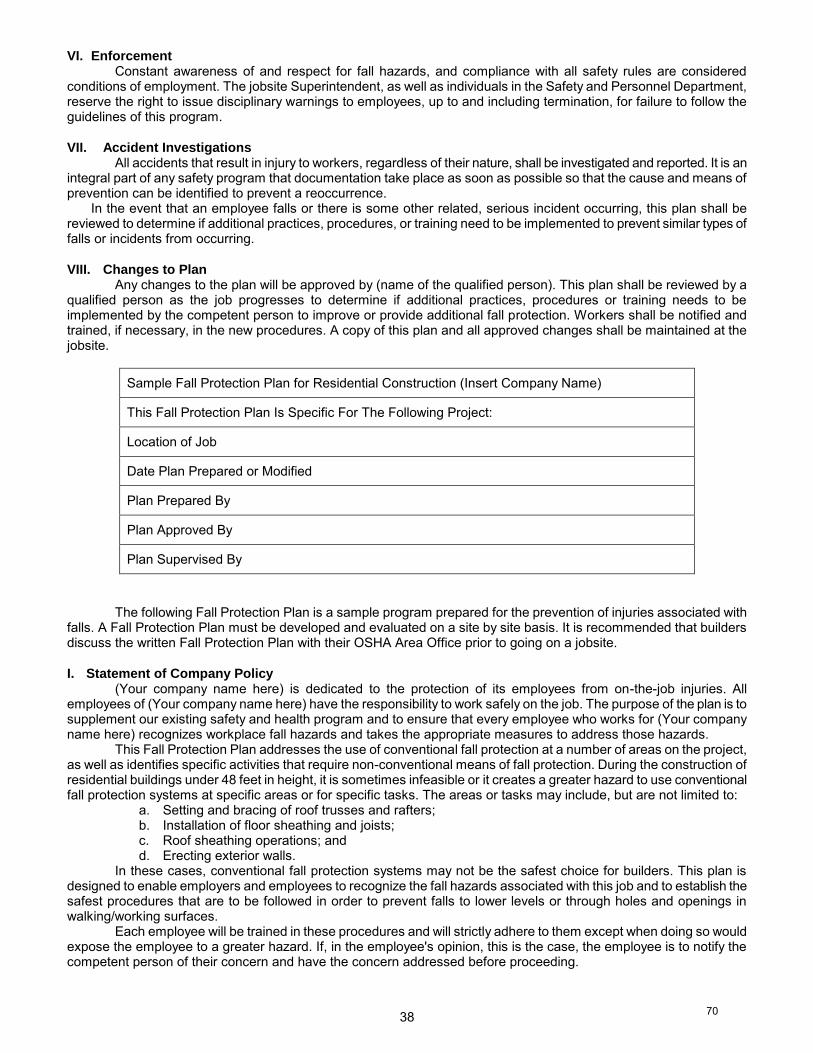
38
VI. EnforcementConstant awareness of and respect for fall hazards, and compliance with all safety rules are considered
conditions of employment. The jobsite Superintendent, as well as individuals in the Safety and Personnel Department,reserve the right to issue disciplinary warnings to employees, up to and including termination, for failure to follow theguidelines of this program.
VII. Accident InvestigationsAll accidents that result in injury to workers, regardless of their nature, shall be investigated and reported. It is an
integral part of any safety program that documentation take place as soon as possible so that the cause and means ofprevention can be identified to prevent a reoccurrence.
In the event that an employee falls or there is some other related, serious incident occurring, this plan shall bereviewed to determine if additional practices, procedures, or training need to be implemented to prevent similar types offalls or incidents from occurring.
VIII. Changes to PlanAny changes to the plan will be approved by (name of the qualified person). This plan shall be reviewed by a
qualified person as the job progresses to determine if additional practices, procedures or training needs to beimplemented by the competent person to improve or provide additional fall protection. Workers shall be notified andtrained, if necessary, in the new procedures. A copy of this plan and all approved changes shall be maintained at thejobsite.
Sample Fall Protection Plan for Residential Construction (Insert Company Name)
This Fall Protection Plan Is Specific For The Following Project:
Location of Job
Date Plan Prepared or Modified
Plan Prepared By
Plan Approved By
Plan Supervised By
The following Fall Protection Plan is a sample program prepared for the prevention of injuries associated withfalls. A Fall Protection Plan must be developed and evaluated on a site by site basis. It is recommended that buildersdiscuss the written Fall Protection Plan with their OSHA Area Office prior to going on a jobsite.
I. Statement of Company Policy (Your company name here) is dedicated to the protection of its employees from on-the-job injuries. All
employees of (Your company name here) have the responsibility to work safely on the job. The purpose of the plan is tosupplement our existing safety and health program and to ensure that every employee who works for (Your companyname here) recognizes workplace fall hazards and takes the appropriate measures to address those hazards.
This Fall Protection Plan addresses the use of conventional fall protection at a number of areas on the project,as well as identifies specific activities that require non-conventional means of fall protection. During the construction ofresidential buildings under 48 feet in height, it is sometimes infeasible or it creates a greater hazard to use conventionalfall protection systems at specific areas or for specific tasks. The areas or tasks may include, but are not limited to:
a. Setting and bracing of roof trusses and rafters;b. Installation of floor sheathing and joists;c. Roof sheathing operations; andd. Erecting exterior walls.
In these cases, conventional fall protection systems may not be the safest choice for builders. This plan isdesigned to enable employers and employees to recognize the fall hazards associated with this job and to establish thesafest procedures that are to be followed in order to prevent falls to lower levels or through holes and openings inwalking/working surfaces.
Each employee will be trained in these procedures and will strictly adhere to them except when doing so wouldexpose the employee to a greater hazard. If, in the employee's opinion, this is the case, the employee is to notify thecompetent person of their concern and have the concern addressed before proceeding.
70
39
It is the responsibility of (name of competent person) to implement this Fall Protection Plan. Continualobservational safety checks of work operations and the enforcement of the safety policy and procedures shall beregularly enforced. The crew supervisor or foreman (insert name) is responsible for correcting any unsafe practices orconditions immediately.
It is the responsibility of the employer to ensure that all employees understand and adhere to the procedures ofthis plan and to follow the instructions of the crew supervisor. It is also the responsibility of the employee to bring tomanagement's attention any unsafe or hazardous conditions or practices that may cause injury to either themselves orany other employees. Any changes to the Fall Protection Plan must be approved by (name of qualified person).
II. Fall Protection Systems To Be Used on This JobInstallation of roof trusses/rafters, exterior wall erection, roof sheathing, floor sheathing and joist/truss activities
will be conducted by employees who are specifically trained to do this type of work and are trained to recognize the fallhazards. The nature of such work normally exposes the employee to the fall hazard for a short period of time. This Plandetails how (Your company name here) will minimize these hazards.
Controlled Access ZonesWhen using the Plan to implement the fall protection options available, workers must be protected through
limited access to high hazard locations. Before any non-conventional fall protection systems are used as part of the workplan, a controlled access zone (CAZ) shall be clearly defined by the competent person as an area where a recognizedhazard exists. The demarcation of the CAZ shall be communicated by the competent person in a recognized manner,either through signs, wires, tapes, ropes or chains.
(Your company name here) shall take the following steps to ensure that the CAZ is clearly marked or controlledby the competent person:
All access to the CAZ must be restricted to authorized entrants;All workers who are permitted in the CAZ shall be listed in the appropriate sections of the Plan (or be visibly
identifiable by the competent person) prior to implementation;The competent person shall ensure that all protective elements of the CAZ be implemented prior to the
beginning of work.Installation Procedures for Roof Truss and Rafter ErectionDuring the erection and bracing of roof trusses/rafters, conventional fall protection may present a greater hazard
to workers. On this job, safety nets, guardrails and personal fall arrest systems will not provide adequate fall protectionbecause the nets will cause the walls to collapse, while there are no suitable attachment or anchorage points forguardrails or personal fall arrest systems.
On this job, requiring workers to use a ladder for the entire installation process will cause a greater hazardbecause the worker must stand on the ladder with his back or side to the front of the ladder. While erecting the truss orrafter the worker will need both hands to maneuver the truss and therefore cannot hold onto the ladder. In addition,ladders cannot be adequately protected from movement while trusses are being maneuvered into place. Many workersmay experience additional fatigue because of the increase in overhead work with heavy materials, which can also lead toa greater hazard.
Exterior scaffolds cannot be utilized on this job because the ground, after recent backfilling, cannot support thescaffolding. In most cases, the erection and dismantling of the scaffold would expose workers to a greater fall hazardthan erection of the trusses/rafters.
On all walls eight feet or less, workers will install interior scaffolds along the interior wall below the location wherethe trusses/rafters will be erected. "Sawhorse" scaffolds constructed of 46 inch sawhorses and 2x10 planks will oftenallow workers to be elevated high enough to allow for the erection of trusses and rafters without working on the top plateof the wall.
In structures that have walls higher than eight feet and where the use of scaffolds and ladders would create agreater hazard, safe working procedures will be utilized when working on the top plate and will be monitored by the crewsupervisor. During all stages of truss/rafter erection the stability of the trusses/rafters will be ensured at all times.
(Your company name here) shall take the following steps to protect workers who are exposed to fall hazardswhile working from the top plate installing trusses/rafters:
Only the following trained workers will be allowed to work on the top plate during roof truss or rafter installation:Workers shall have no other duties to perform during truss/rafter erection procedures;All trusses/rafters will be adequately braced before any worker can use the truss/rafter as a support;Workers will remain on the top plate using the previously stabilized truss/rafter as a support while other
trusses/rafters are being erected;Workers will leave the area of the secured trusses only when it is necessary to secure another truss/rafter;The first two trusses/rafters will be set from ladders leaning on side walls at points where the walls can support
the weight of the ladder; andA worker will climb onto the interior top plate via a ladder to secure the peaks of the first two trusses/rafters
being set.The workers responsible for detaching trusses from cranes and/or securing trusses at the peaks traditionally are
positioned at the peak of the trusses/rafters. There are also situations where workers securing rafters to ridge beams willbe positioned on top of the ridge beam.
71
40
(Your company name here) shall take the following steps to protect workers who are exposed to fall hazards while securing trusses/rafters at the peak of the trusses/ridge beam:
Only the following trained workers will be allowed to work at the peak during roof truss or rafter installation: Once truss or rafter installation begins, workers not involved in that activity shall not stand or walk below or
adjacent to the roof opening or exterior walls in any area where they could be struck by falling objects; Workers shall have no other duties than securing/bracing the trusses/ridge beam; Workers positioned at the peaks or in the webs of trusses or on top of the ridge beam shall work from a stable
position, either by sitting on a "ridge seat" or other equivalent surface that provides additional stability or by positioning themselves in previously stabilized trusses/rafters and leaning into and reaching through the trusses/rafters;
Workers shall not remain on or in the peak/ridge any longer than necessary to safely complete the task. Roof Sheathing Operations Workers typically install roof sheathing after all trusses/rafters and any permanent truss bracing is in place. Roof
structures are unstable until some sheathing is installed, so workers installing roof sheathing cannot be protected from fall hazards by conventional fall protection systems until it is determined that the roofing system can be used as an anchorage point. At that point, employees shall be protected by a personal fall arrest system.
Trusses/rafters are subject to collapse if a worker falls while attached to a single truss with a belt/harness. Nets could also cause collapse, and there is no place to attach guardrails.
All workers will ensure that they have secure footing before they attempt to walk on the sheathing, including cleaning shoes/boots of mud or other slip hazards.
To minimize the time workers must be exposed to a fall hazard, materials will be staged to allow for the quickest installation of sheathing.
(Your company name here) shall take the following steps to protect workers who are exposed to fall hazards while installing roof sheathing:
Once roof sheathing installation begins, workers not involved in that activity shall not stand or walk below or adjacent to the roof opening or exterior walls in any area where they could be struck by falling objects;
The competent person shall determine the limits of this area, which shall be clearly communicated to workers prior to placement of the first piece of roof sheathing;
The competent person may order work on the roof to be suspended for brief periods as necessary to allow other workers to pass through such areas when this would not create a greater hazard;
Only qualified workers shall install roof sheathing; The bottom row of roof sheathing may be installed by workers standing in truss webs; After the bottom row of roof sheathing is installed, a slide guard extending the width of the roof shall be securely
attached to the roof. Slide guards are to be constructed of no less than nominal 4" height capable of limiting the uncontrolled slide of workers. Workers should install the slide guard while standing in truss webs and leaning over the sheathing;
Additional rows of roof sheathing may be installed by workers positioned on previously installed rows of sheathing. A slide guard can be used to assist workers in retaining their footing during successive sheathing operations; and
Additional slide guards shall be securely attached to the roof at intervals not to exceed 13 feet as successive rows of sheathing are installed. For roofs with pitches in excess of 9-in-12, slide guards will be installed at four-foot intervals.
When wet weather (rain, snow, or sleet) are present, roof sheathing operations shall be suspended unless safe footing can be assured for those workers installing sheathing.
When strong winds (above 40 miles per hour) are present, roof sheathing operations are to be suspended unless wind breakers are erected. Installation of Floor Joists and Sheathing During the installation of floor sheathing/joists (leading edge construction), the following steps shall be taken to protect workers:
Only the following trained workers will be allowed to install floor joists or sheathing: Materials for the operations shall be conveniently staged to allow for easy access to workers; The first floor joists or trusses will be rolled into position and secured either from the ground, ladders or
sawhorse scaffolds; Each successive floor joist or truss will be rolled into place and secured from a platform created from a sheet of
plywood laid over the previously secured floor joists or trusses; Except for the first row of sheathing which will be installed from ladders or the ground, workers shall work from
the established deck; and Any workers not assisting in the leading edge construction while leading edges still exist (e.g. cutting the decking
for the installers) shall not be permitted within six feet of the leading edge under construction. Erection of Exterior Walls During the construction and erection of exterior walls, employers shall take the following steps to protect
workers: Only the following trained workers will be allowed to erect exterior walls: A painted line six feet from the perimeter will be clearly marked prior to any wall erection activities to warn of the
approaching unprotected edge; Materials for operations shall be conveniently staged to minimize fall hazards; and
72
41
Workers constructing exterior walls shall complete as much cutting of materials and other preparation aspossible away from the edge of the deck.
III. EnforcementConstant awareness of and respect for fall hazards, and compliance with all safety rules are considered
conditions of employment. The crew supervisor or foreman, as well as individuals in the Safety and PersonnelDepartment, reserve the right to issue disciplinary warnings to employees, up to and including termination, for failure tofollow the guidelines of this program.
IV. Accident InvestigationsAll accidents that result in injury to workers, regardless of their nature, shall be investigated and reported. It is an
integral part of any safety program that documentation take place as soon as possible so that the cause and means ofprevention can be identified to prevent a reoccurrence.
In the event that an employee falls or there is some other related, serious incident occurring, this plan shall bereviewed to determine if additional practices, procedures, or training need to be implemented to prevent similar types offalls or incidents from occurring.
V. Changes to Plan Any changes to the plan will be approved by (name of the qualified person). This plan shall be reviewed by a
qualified person as the job progresses to determine if additional practices, procedures or training needs to beimplemented by the competent person to improve or provide additional fall protection. Workers shall be notified andtrained, if necessary, in the new procedures. A copy of this plan and all approved changes shall be maintained at thejobsite.
[59 FR 40746, Aug. 9, 1994; 60 FR 5131, Jan. 26, 1995]
73

Enforcement Policy
MIOSHA Construction Safety and Health Division
Michigan Occupational Safety and Health Administration
Department of Licensing and Regulatory Affairs (LARA)
DIVISION
INSTRUCTION
DOCUMENT IDENTIFIER:
CSHD-COM-04-1R2
DATE:
March 30, 2015
SUBJECT: Residential Fall Protection Compliance Criteria
I. Purpose. This instruction establishes MIOSHA enforcement policy on fall protection for
residential construction activities.
II. Scope. This instruction applies to the Construction Safety and Health Division.
III. References.
A. MIOSHA Construction Safety Standard Part 11. /R408.41101 et seq., Fixed and
Portable Ladders.
B. MIOSHA Construction Safety Standard Part 12. /R408.41201 et seq., Scaffolds
and Scaffold Platforms.
C. MIOSHA Construction Safety Standard Part 32. /R408.43201 et seq., Aerial
Work Platforms.
D. MIOSHA Construction Safety Standard Part 45. /R408.44501 et seq., Fall
Protection.
E. Occupational Safety and Health Administration (OSHA) Instruction STD 03-11-
002, December 16, 2010, Compliance Guidelines for Residential Construction.
F. OSHA Instruction STD 03-00-001, June 18, 1999, Interim Fall Protection
Compliance Guidelines for Residential Construction.
G. OSHA 29 CFR Part 1926-Subpart M, Fall Protection.
IV. Distribution. MIOSHA Staff; OSHA Lansing Area Office; General; S-drive Accessible;
MIOSHA Weekly; and Internet Accessible.
V. Cancellations. All previous versions of this division instruction.
VI. History. History of previous versions include:
CSHD-COM-04-1R1, March 25, 2011.
CSHD-COM-04-1, June 25, 2004.
VII. Contact. Lawrence Hidalgo, Director, Construction Safety and Health Division
VIII. Originator: Lawrence Hidalgo, Director
IX. Significant Changes. Reformatted according to the new DMS instruction.
X. Background. The fall protection requirements for residential construction are located in
Part 45 - Fall Protection, Rule 1926.501(b)(13) which requires fall protection (usually
75

CSHD-COM-04-1R2
March 30, 2015
Residential Fall Protection Compliance Criteria
2
conventional fall protection; e.g., guardrail systems, safety net systems, or personal fall
arrest systems) for work six feet or more above lower levels, except where employers can
demonstrate that such fall protection systems are infeasible or would create a greater
hazard. Although the standard does not mention personal fall restraint systems,
MIOSHA does accept a properly utilized fall restraint system in lieu of a personal fall
arrest system when the restraint system is rigged in such a way that the worker is not
exposed to the fall hazard.
Under 1926.501(b)(13), the employer is not required to use conventional fall protection if
they can demonstrate that doing so is infeasible or would pose a greater hazard. Instead,
in that situation, the employer must develop and implement a written site-specific fall
protection plan meeting the requirements of 1926.502(k).
Flexible language was included in 1926.501(b)(13) because of concerns expressed by
some commenters during rulemaking about the feasibility and safety of using
conventional fall protection for residential construction. As a result, the Construction
Safety and Health Division issued the initial instruction of Residential Fall Protection
Compliance Criteria on June 24, 2004, which permitted employers engaged in certain
residential construction activities to use alternative fall protection measures instead of
conventional fall protection. These alternative measures could be used without showing
infeasibility or greater hazard and without a written site-specific fall protection plan.
This instruction was an interim policy and was never intended to remain as the final
policy on fall protection for residential construction activities.
This instruction defined “residential construction” as “structures where the working
environment and the construction materials, methods, and procedures employed were
essentially the same as those used for typical house (single-family dwelling) and
townhouse construction. The instruction stated that “discrete parts of a large commercial
structure . . . could come within the scope of the directive (for example, a shingled
entranceway to a mall), but . . . that did not mean that the entire structure thereby came
within the terms of the directive.” This definition of “residential construction” is not
clear and has created confusion for the residential industry and inconsistency in
enforcement.
In summary, following the original intent of 1926.501(b)(13) would eliminate confusion
in the residential construction industry as to what fall protection methods and systems
must be used to be in compliance with MIOSHA fall protection requirements.
XI. Rationale for Revising the initial instruction, dated June 24, 2004. There continues to be
high numbers of fall-related fatalities in residential construction. With OSHA’s decision
to rescind STD 03-00-001, Plain Language Revision of OSHA Instruction STD 3.1,
Interim Fall Protection Compliance for Residential Construction, MIOSHA is required to
be “as effective as OSHA.” Many different fall protection options are available to
employers that can be used for almost all residential construction operations. This
provides separate and independent grounds for MIOSHA's decision to revise this
instruction.
76
CSHD-COM-04-1R2
March 30, 2015
Residential Fall Protection Compliance Criteria
3
There may be isolated situations in which it is infeasible or creates a greater hazard to use
conventional fall protection in residential construction and 1926.501(b)(13) provides
sufficient flexibility to accommodate employers in these situations. Any employer
engaged in residential construction who can demonstrate that the use of conventional fall
protection is infeasible or creates a greater hazard may use a fall protection plan and
alternative fall protection measures in accordance with Part 45 Fall Protection
1926.502(k). Employers also have the option of having workers work from scaffolds (in
compliance with Part 12), ladders (in compliance with Part 11) or aerial lifts (in
compliance with Part 32) instead of complying with 1926.501(b)(13). Additional
methods of fall protection can be found in Appendix A. Revising this instruction and
enforcing the original intent of 1926.501(b)(13) for fall protection for residential
construction will provide appropriate protection for workers and sufficient compliance
flexibility for employers. For these reasons, the Agency is hereby revising this
instruction.
XII. Residential Construction. For purposes of determining the applicability of section
1926.501(b)(13), the term "residential construction" is interpreted as covering
construction work that satisfies the following elements:
A. The end-use of the structure is required to be a home or dwelling. This comports
with the plain meaning of the term “residential” in the text of 1926.501(b)(13) and
is consistent with its original intent.
B. The building in question must be constructed using traditional wood frame
construction materials and methods. The term “residential construction” in
1926.501(b)(13) was designed to apply only to the construction of homes using
traditional wood frame construction materials and methods. This includes the
construction of otherwise covered residences if there is limited use of structural
steel in a predominantly wood-framed home, such as a steel I-beam to support
wood framing.
Accordingly, it is acceptable within the bounds of “traditional wood frame
construction materials and methods” to use cold-formed sheet metal studs in
framing.
Many homes and townhouses are built using traditional wood frame construction
throughout the structure except for the exterior walls, which are often built with
masonry brick or block. The same fall protection methods are likely to be used in
the construction of homes built with wood framed and masonry brick or block
exterior walls and are consistent with the original intent of 1926.501(b)(13); thus
allowing the construction of residences using masonry brick or block for the
exterior walls as residential construction.
In accordance with the discussion above, and for purposes of the interpretation of
“residential construction” adopted herein, “traditional wood frame construction
materials and methods” will be characterized by:
1. Framing materials: Wood (or equivalent cold-formed sheet metal stud)
framing, not steel or concrete; wooden floor joists and roof structures.
77
CSHD-COM-04-1R2
March 30, 2015
Residential Fall Protection Compliance Criteria
4
2. Exterior wall structure: Wood (or equivalent cold-formed sheet metal
stud) framing or masonry brick or block.
3. Methods: Traditional wood frame construction techniques.
C. Nursing homes, hotels, and similar facilities. To meet the definition of
“residential construction,” the end use of the building must be as a home or
dwelling and the building must be constructed using traditional wood frame
construction materials and method. Construction of nursing homes, hotels, and
similar facilities typically involves the use of the following materials in the
framework of the structure: precast concrete, steel I-beams (beyond the limited
use of steel I-beams in conjunction with wood framing, described above), rebar,
and/or poured concrete. These materials are not used in traditional wood frame
construction. Buildings that are constructed using these materials will not be
considered “residential construction” for purposes of 1926.501(b)(13). However,
there may be unusual situations in which a project such as a hotel, motel, or
nursing home is being constructed using traditional wood frame construction
materials and methods and may meet the definition of “residential construction.”
These will be evaluated on a case-by-case basis.
XIII. Citation Policy.
A. If an employer engaged in residential construction activities (e.g., carpentry,
plumbing, electrical installation) does not provide guardrail systems, safety net
arrest systems, personal fall arrest systems, or other fall protection allowed under
1926.501(b), a citation for violating 1926.501(b)(13) will be issued unless the
employer can demonstrate the infeasibility of these protective measures or the
existence of a greater hazard.
B. If the employer demonstrates infeasibility or a greater hazard, the safety officer
must determine if the employer has implemented a fall protection plan meeting
the requirements of 1926.502(k). Part of that determination will be based on
whether the employer has instituted alternative measures to reduce or eliminate
fall hazards.
C. All fall protection plans under 1926.502(k) are to be in writing and be site-
specific. If the fall protection plan is not written, site-specific, or otherwise fails
to meet the requirements of 1926.502(k), the violation should be cited as a
grouped citation of 1926.501(b)(13) and 1926.502(k). A written plan developed
for repetitive use for a particular style/model home will be considered site-
specific with respect to a particular site only if it fully addresses all issues related
to fall protection at that site.
78
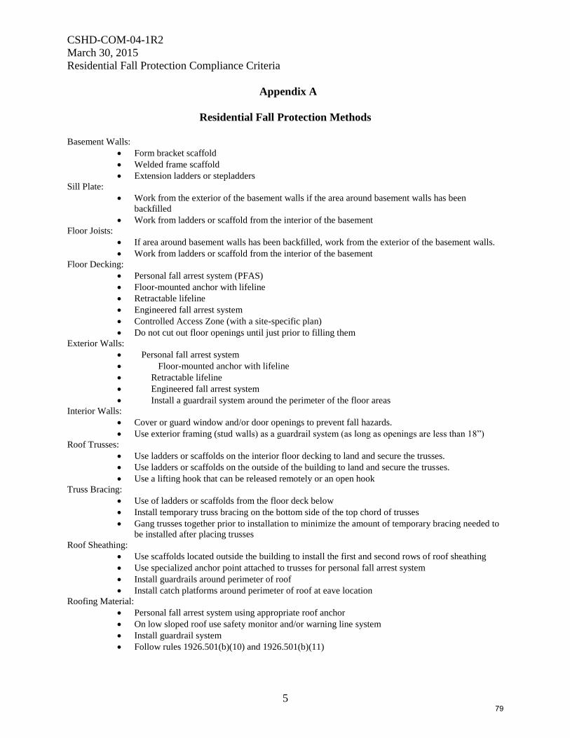
CSHD-COM-04-1R2
March 30, 2015
Residential Fall Protection Compliance Criteria
5
Appendix A
Residential Fall Protection Methods
Basement Walls:
Form bracket scaffold
Welded frame scaffold
Extension ladders or stepladders
Sill Plate:
Work from the exterior of the basement walls if the area around basement walls has been
backfilled
Work from ladders or scaffold from the interior of the basement
Floor Joists:
If area around basement walls has been backfilled, work from the exterior of the basement walls.
Work from ladders or scaffold from the interior of the basement
Floor Decking:
Personal fall arrest system (PFAS)
Floor-mounted anchor with lifeline
Retractable lifeline
Engineered fall arrest system
Controlled Access Zone (with a site-specific plan)
Do not cut out floor openings until just prior to filling them
Exterior Walls:
Personal fall arrest system
Floor-mounted anchor with lifeline
Retractable lifeline
Engineered fall arrest system
Install a guardrail system around the perimeter of the floor areas
Interior Walls:
Cover or guard window and/or door openings to prevent fall hazards.
Use exterior framing (stud walls) as a guardrail system (as long as openings are less than 18”)
Roof Trusses:
Use ladders or scaffolds on the interior floor decking to land and secure the trusses.
Use ladders or scaffolds on the outside of the building to land and secure the trusses.
Use a lifting hook that can be released remotely or an open hook
Truss Bracing:
Use of ladders or scaffolds from the floor deck below
Install temporary truss bracing on the bottom side of the top chord of trusses
Gang trusses together prior to installation to minimize the amount of temporary bracing needed to
be installed after placing trusses
Roof Sheathing:
Use scaffolds located outside the building to install the first and second rows of roof sheathing
Use specialized anchor point attached to trusses for personal fall arrest system
Install guardrails around perimeter of roof
Install catch platforms around perimeter of roof at eave location
Roofing Material:
Personal fall arrest system using appropriate roof anchor
On low sloped roof use safety monitor and/or warning line system
Install guardrail system
Follow rules 1926.501(b)(10) and 1926.501(b)(11)
79

Sample Fall Protection Plan & Templates
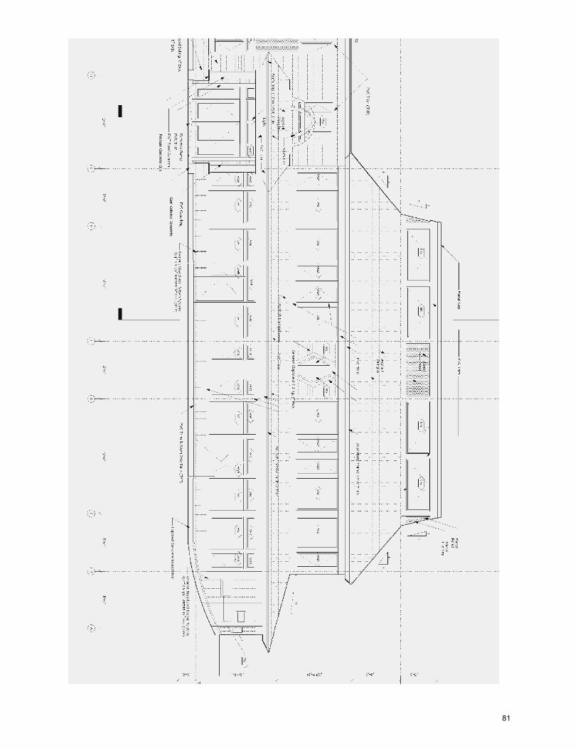
81
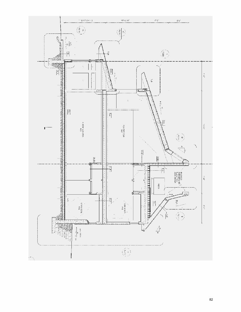
82

SAFETY POLICIES AND PROCEDURES
Sample House Boomtown, MI
83

JHA Review The following people have review the JHA for this project:
PRINT SIGNATURE 1 2 3 4 5 6 7 8 9 10 11 12 13 14 15 16 17 18 19 20
84
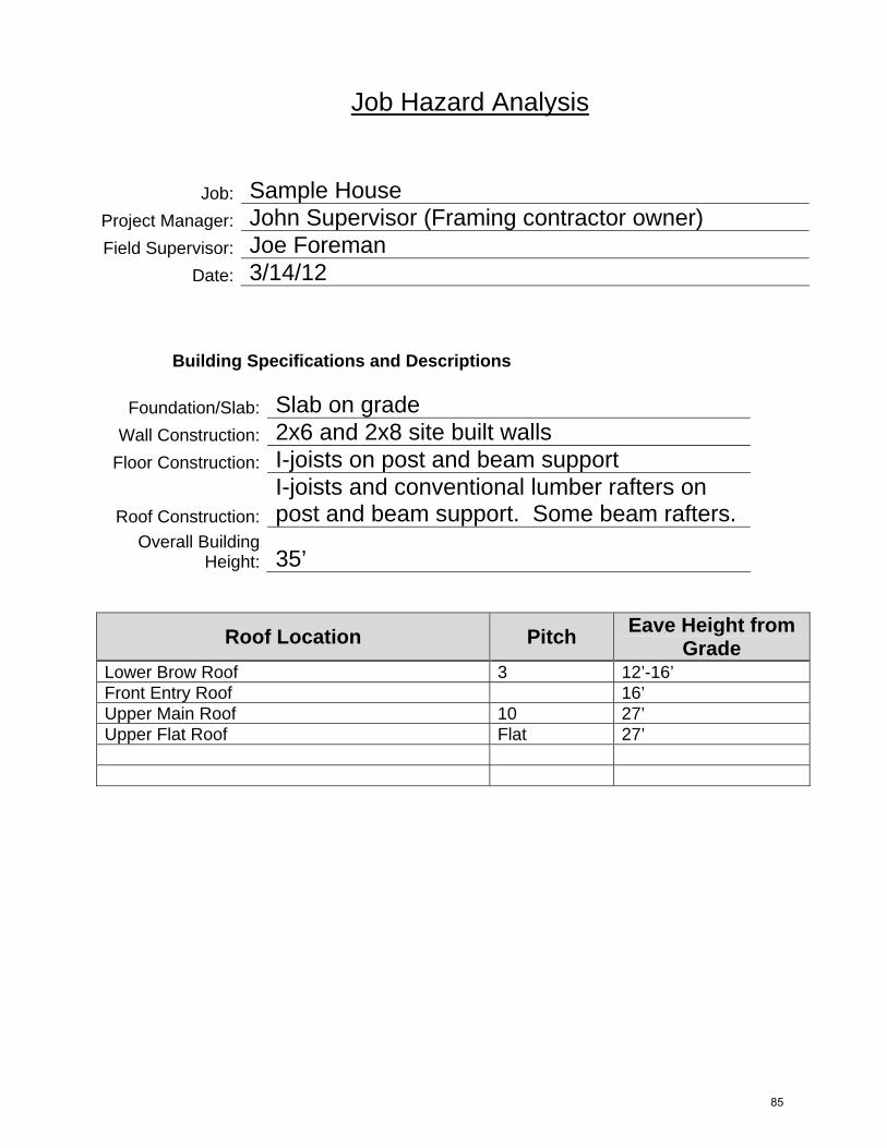
Job Hazard Analysis
Job: Sample House Project Manager: John Supervisor (Framing contractor owner) Field Supervisor: Joe Foreman
Date: 3/14/12
Building Specifications and Descriptions
Foundation/Slab: Slab on grade Wall Construction: 2x6 and 2x8 site built walls
Floor Construction: I-joists on post and beam support
Roof Construction: I-joists and conventional lumber rafters on post and beam support. Some beam rafters.
Overall Building Height: 35’
Roof Location Pitch Eave Height from Grade
Lower Brow Roof 3 12’-16’ Front Entry Roof 16’ Upper Main Roof 10 27’ Upper Flat Roof Flat 27’
85
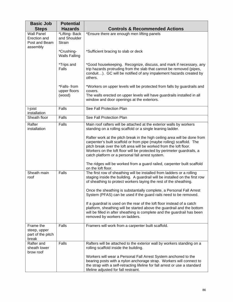
Basic Job Steps
Potential Hazards Controls & Recommended Actions
Wall Panel Erection and Post and Beam assembly
*Lifting- Backand Shoulder Strain
*Crushing-Walls Falling
*Trips andFalls
*Falls- fromupper floors (wood)
*Ensure there are enough men lifting panels
*Sufficient bracing to slab or deck
*Good housekeeping. Recognize, discuss, and mark if necessary, anytrip hazards protruding from the slab that cannot be removed (pipes, conduit…). GC will be notified of any impalement hazards created by others.
*Workers on upper levels will be protected from falls by guardrails andcovers. The walls erected on upper levels will have guardrails installed in all window and door openings at the exteriors.
I-joist installation
Falls See Fall Protection Plan
Sheath floor Falls See Fall Protection Plan
Rafter installation
Falls Main roof rafters will be attached at the exterior walls by workers standing on a rolling scaffold or a single leaning ladder.
Rafter work at the pitch break in the high ceiling area will be done from carpenter’s built scaffold or from pipe (maybe rolling) scaffold. The pitch break over the loft area will be worked from the loft floor. Workers on the loft floor will be protected by perimeter guardrails, a catch platform or a personal fall arrest system.
The ridges will be worked from a guard railed, carpenter built scaffold on the loft floor.
Sheath main roof
Falls The first row of sheathing will be installed from ladders or a rolling staging inside the building. A guardrail will be installed on the first row of sheathing to protect workers laying the rest of the sheathing.
Once the sheathing is substantially complete, a Personal Fall Arrest System (PFAS) can be used if the guard rails need to be removed.
If a guardrail is used on the rear of the loft floor instead of a catch platform, sheathing will be started above the guardrail and the bottom will be filled in after sheathing is complete and the guardrail has been removed by workers on ladders.
Frame the steep, upper part of the pitch break
Falls Framers will work from a carpenter built scaffold.
Rafter and sheath lower brow roof
Falls Rafters will be attached to the exterior wall by workers standing on a rolling scaffold inside the building.
Workers will wear a Personal Fall Arrest System anchored to the bearing posts with a nylon anchorage strap. Workers will connect to the strap with a self-retracting lifeline for fall arrest or use a standard lifeline adjusted for fall restraint.
86
Fall Protection This plan is written in compliance with 29 CFR Part 1926.501(b)(13), 29 CFR Part 1926.501(b)(2)(i) and OSHA Directive STD 03‐11‐002. As directed by those regulations, this plan is formatted to meet the requirements of 1926.502(k). This fall protection supplement is specific for the following project: Job: Sample House City: Boomtown, MI Prepared by: John Supervisor on: 3/14/12 Implemented and Supervised by: Joe Foreman Approved by: Safety Director, Supervisor or Owner The Company is dedicated to the protection of its employees from on‐the‐job injuries. All employees of The Company have the responsibility to work safely on the job. The purpose of this supplement is to establish the safest procedures that are to be followed in order to prevent injuries when conventional means of safety are inadequate and potentially increase hazard exposure. Controlling exposures to occupational hazards is the fundamental method of protecting workers. Traditionally, The Company uses this hierarchy of controls as a means of determining how to implement feasible and effective controls:
• Elimination • Substitution • Engineering controls • Administrative controls • Personal protective equipment
Methods contained in this plan are site specific and have been developed based on this job’s characteristics, conditions, and potential risks. The safest methods herein are derived from the collective experience of senior employees of The Company and careful consideration of these information sources:
• The Company Injury Data1 ‐ The greatest indicator as to where improvements need to be made is found in a review of our own injury data. The total number of injuries show the frequency, while collective claims and average claims per injury indicate severity. Given the data below, The Company applies the most emphasis on reducing and eliminating exertion/ MSDs, falls from scaffolding, and ladder injuries. Exertions/Muscular Skeletal Disorders (MSDs) are in need of the most improvement as
1 Statistics provided by The Company’s worker’s comp carrier
87
they represent the highest frequency and the highest total claims. Although ladder injuries and falls from scaffolding are low in frequency, their high collective claim numbers and their high average claims indicate they are high in severity. The most severe injury in our history was a fatality from a nailgun shot into the heart of the user. See Worker Position on page 7
o Injury count in descending order – January 2007 to November 201121.88% Exertion, Muscular Skeletal Disorders (MSD)17.19% Lacerations16.56% Struck By / Struck Against11.88% Caught Between / Crush By10.00% Nail Gun8.75% Slip Trip5.94% Eye injuries2.81% Ladder2.50% Falls from Trusses1.56% Falls from Scaffolding0.63% Miscellaneous0.31% Falls from Upper Level
o The highest collective claims in descending order are: exertion / MSD, ladderinjuries, slip / trip and falls from scaffolding with all others being significantlylower
o The highest average claims per injury in descending order are: falls fromscaffolding, ladder use injuries and falls from trusses with all others beingsignificantly lower.
The Company’s safety program must focus on reducing MSD’s, falls from scaffolding, and ladder injuries to improve workers’ health and safety.
• Census of Fatal Occupational Injuries (CFOI) by the Bureau of Labor Statistics – Theinformation from these reports drives safety attention to falls. Falls have been thesecond leading cause of on‐the‐job fatalities, behind highway incidents, since 1998.For the past six years, the Specialty Trade Contractors accounted for 64.75% of the fatalfalls in the major category of Construction according to the CFOI.The trades representing higher percentages of fatal falls in the Specialty TradeContractors are:2
Roofing Contractors 26.47% Painting and Wall Covering Contractors 9.61% Structural Steel and Precast Concrete Contractors 7.96%
2 Information has been compiled from data presented by the Bureau of Labor Statistics in the Census of Fatal Occupational Injuries from 2005-2010 inclusive
88
Electrical Contractors 7.60% Plumbing, HVAC Contractors 7.53% Masonry Contractors 6.31% Framing Contractors 5.74%
The BLS data shows a pattern of exposure consistent with our own history that injuries from falls are a lower risk with framing contractors. Census of Fatal Occupational Injuries data regarding the circumstances of fatal falls (Event or Exposure)3 indicates that the majority of fatal falls in the last eight years are caused by:
o Fall from a roof (19.61%)o Fall from a ladder (17.17%)o Fall to a lower level (14.36%)
The Company’s safety program focuses on reducing these exposures by putting high priority on roof edge protection, reducing the use of ladders as much as possible, and putting high priority on protecting the perimeter of upper levels, shafts, and wells in the floors.
89
Framing operations that are performed without conventional means of fall protection will be conducted by employees who are trained and sufficiently experienced to do this work and recognize the fall hazards. The nature of this work presents a fall exposure for a short period of time. This plan analyzes potential safety measures and installation methods used to determine the safest installation procedures for this job.
When using this plan, workers from other companies will be protected through limited access to high hazard locations. A Controlled Access Zone (CAZ) will be clearly designated by the competent person as an area where the recognized hazard exists. All access to the CAZ will be restricted to the company’s employees and authorized entrants.
Framers are exposed to many potential hazards during floor truss installation, roof truss installation, and leading edge operations. Many factors need to be considered: fall protection, handling and stocking methods, worker fatigue, over exertion and nail gun projectile hazard.
The effectiveness of these conventional fall protection safety measures has been considered in developing the following plan(s):
• Guardrails‐ Guardrails are a preferred method of fall protection at The Company. Theyare most often used for protection of working surfaces and scaffold walkways but arelimited in their effectiveness for protecting a truss installer as well as infeasible for useat a leading edge. Guardrails may be used, if appropriate for the operation, to protectworkers from falling at the exterior of the building or into framed, fixed openings withinthe floor system such as stairwells, chases and shafts.
• Safety Nets‐ In wood frame construction, safety nets are not capable of protecting trussinstallers from injury, because while safety net manufacturers test nets for ANSI andOSHA requirements, the anchorage has not been tested. The drop test certification forthe Residential Safety Net by InCord was performed on their net while it was suspendedfrom steel beams. A safety net in a wood framed building would have to be anchored tothe top plates of temporarily braced bearing walls. This anchorage method is untestedand unreliable. Furthermore, the use of safety nets was disqualified in the Subpart MAppendix E sample plan for that reason. The plan cites the inadequate strength of thebraced wall to act as a safety net anchorage. Safety nets require clearance underneaththem to absorb the fall. In a wood framed building the net would span across interiorwalls and braces, and a falling worker would suffer injuries from these obstructions.
• Personal Fall Arrest Systems (PFAS) are not effective in most rough framing operationsand not allowed in truss systems until they are completely sheathed restrained and
8 Washington State Department of Labor and Industries: Fall Protection, Fall Restraint & Fall Arrest
90
diagonally braced.9 The Company will carefully assess conditions to see if PFAS will be effective protection for the wearer and will neither endanger others nor risk collapsing any part of the structure. The following requirements often cannot be met and must be carefully examined to ensure safe use of PFAS; otherwise the use of PFAS is a false sense of security:
o Anchorage. There are a multitude of anchorage connectors available todayincluding: nail and screw plates, truss bars, horizontal lines, hook anchors andbeam straps among others. The anchorage that any anchorage connector isattached to must be able to resist the maximum arresting force of a fall;potentially five thousand pounds. Partially installed trusses are incapable ofwithstanding a fall arrest force. Walls and their components are incapable ofwithstanding the impact and they are only temporarily braced for straightnessuntil trusses are installed.
o Freefall. Every effort will be made to configure a combination of equipment andanchorage location that will limit the freefall to less than 6’. Properconfiguration requires anchorage to be overhead and usually there is nostructure overhead during the installation of trusses. The floor and supportingbeams underneath the bottoms of the bearing walls is usually the nearestcomplete, capable structure.
o Total fall distance. Should the criteria for anchorage strength and freefalldistance be met, total fall distance from the trusses inside the building must bereviewed. The distance is often too short for lanyards and self retracting lifelinesto prevent a worker from hitting the lower level.
• Personal Fall Restraint Systems (PFRS) are seldom appropriate for truss installation asthere usually is no walkway, platform, or floor available that restraint would be effectiveprotection for the truss installer.
• Catch platforms at the exterior of the building are extremely effective to protectworkers from the greater fall hazard. They are a preferred fall protection method of TheCompany and will be frequently used for perimeter protection. They are usuallyinfeasible inside the building. Due to the congestion of typical temporary bracing, theplatform would need to be small and portable making it virtually ineffective.
Fall hazards have the potential to be engineered out of the task using certain conventional methods for working at heights. These methods come with their own inherent usage hazards to consider:
• Scaffolding is frequently used to increase the safety of the installer as either a catchplatform or a work platform. The erection, access to the platform, use and disassemblymay increase the workers exposure to a fall hazard. The use of scaffold increases theworkload and therefore increases the hazard exposure. Nailgun hazards potentiallybecome more severe when working from a scaffold as the gun is shooting in the vicinity
9 Structural Building Components Association. BCSI-B11
91
of vital organs; ideally the gun will be used near the workers feet, away from those vital organs. Scaffold related hazards cannot outweigh the hazards it is supposed to mitigate.
o Carpenters’ Wall Bracket Scaffold can be used as a walkway for the trussinstaller to work from on exterior bearing walls. Workers can be protected fromfalls to the outside of the scaffold by guardrails. The building side of the scaffoldcan usually be left open allowing the truss installer access to the ends of thetrusses as long as the fall distance is less than ten feet to the interior floor.Scaffold is a way to engineer out the fall hazard for the truss installer but scaffoldcomes with its own hazards and the benefits of its use must be weighed againstthe increased exposure to the workers. Besides the use of the scaffold, theseincreased exposures include: the erection of the scaffold, the dismantling of thescaffold and the access to the scaffold. One of the most importantconsiderations for scaffold use is nail gun projectile hazards. The relative heightof the platform must be set so the proximity of the nail gun use is away fromvital upper body parts to reduce the potential severity of a nail gun projectileinjury.
o Interior scaffold (baker scaffold, top plate bracket scaffold, carpenter builtscaffold…) can be a practical way to provide a safe work platform for an installerto stand on while attaching trusses to bearing locations. It is especially feasiblefor, but not limited to, situations where the bearing location is a wood framedwall. As with all scaffold; erection, access, usage, nail gun proximity anddismantling must be considered. An interior scaffolding may provide noadvantage in certain circumstances. A walkway set at the height of the bearingwall provides the best worker position to minimize nail gun proximity concernsbut may not be any safer than walking on the bottom chords of stabilizedtrusses. The use of scaffolding increases the workload which increases hazardexposure. Interior scaffolding will not be practical for tall trusses when theplatform needs to be more than ten feet off the lower level. The guardrailbutted to the bottom of the truss may not allow the installer to handle and bracethe tops of the trusses safely.
o Scissor lifts will provide a safe work platform but site condition needs are veryparticular. The floor must support the lift, be smooth and level enough and befree of obstacles. Installers must be able to reach the top chords of the trussesso the guardrail and truss height must be considered to ensure practicality.
o Aerial lifts are very limited in their use for truss installation and may notnecessarily reduce the hazard exposure. Aerial lifts are effective for exterior wallwork, but seldom practical for truss installation. Even if site conditions are met,a worker in an aerial lift is very limited as to how much of the installation can beaccomplished from there.
• Ladders will be used in many parts of our operation but the hazards associated with theuse of ladders often prevent The Company from specifying ladders as a primary meansof working at heights for several tasks:
o Ladders are often hazardous while trying to maneuver heavy materials. Aladder cannot be adequately protected from movement when working with
92
heavy materials, and working with heavy materials may be awkward and cause the worker to lose their balance.
o The weight of the worker and some materials may overload a ladder.o Doing a lot of overhead work from a ladder will eventually fatigue the worker
making the worker more susceptible to injury.o Worker position on a ladder may increase nail gun projectile exposure.
Worker position for the task is a significant consideration. Injury prevention relies greatly on coordinating the worker with the work.
• Over exertion will reduced by making sure the worker is in a position to maneuver andleverage the materials at hand.
• Nail gun—A priority at The Company is positioning nail gun use away from vital bodyparts. The most severe injury in The Company’s history was a death from a nailgun shotinto the heart of the user. A priority is given to using proper methods that position nailgun use away from the worker’s head, face, and torso.
When conventional methods are more hazardous than alternative methods because of the worker position, task, and nature of the work, the following guidelines will be followed while performing the specified tasks:
93
Floor Framing Special Instructions
The Company will take the following steps to protect workers who are exposed to fall hazards while framing and sheathing the corridors and while installing I‐joists:
• A Controlled Access Zone (CAZ) will be established on the floor beneath the floor joistsbeing installed.
• Only designated trained workers will install floor joists. Workers shall have no otherduties to perform during floor framing.
• All materials will be staged so workers have quick and safe access to them in order tominimize the exposure to fall hazards.
I‐joist installation: • Before I‐joists are installed, a guardrail will be in place on the exterior of the building.
This will be there to prevent a fall to the exterior of the building. Any gaps in theguardrails will be filled as the I‐joists are installed.
• I‐joists will be placed on the walls manually or in bulk by forklift or crane.• The first I‐joists will be rolled into position and secured from ladders or a carpenter built
interior walkway scaffold.• Successive I‐joists will be rolled into place and secured from a platform of floor
sheathing laid across previously installed I‐joists. The platform will be similar to ascaffold platform in that it will be at least 18” wide.
• Once a series of I‐joists have been stabilized, workers can work from the I‐joists to detailthe floor system. Detailers may stand between I‐joists on top of intermediate walls.Strips of sheathing, at least 18” wide, may be used as a temporary walkway on top ofsecured floor trusses.
• Workers will never walk the top of walls without I‐joists installed and will never walk thetops of the I‐joists.
94
Leading Edge Work Special Instructions
The Company will take the following steps to protect workers who are exposed to fall hazards while installing floor sheathing:
• Before sheathing is installed, a guardrail will be in place on the exterior of the building.This will be there to prevent a fall to the exterior of the building.
• I‐joists will be adequately secured before sheathing begins.• The first row of sheathing will be installed by workers standing on a temporary platform
laying across the tops of the I‐joists, on the leading edge side of the sheathing.• Successive sheets will be installed from previously installed sheets.• Any workers not involved in laying the sheathing will stay at least 8’ (2 rows) away from
the leading edge.
95

Michigan Department of Licensing and Regulatory Affairs
Michigan Occupational Safety & Health Administration
Consultation Education & Training Division
Sample Fall Protection Plan for
Residential Construction Work
Employers engaged in residential construction work who can demonstrate that it is infeasible or
creates a greater hazard to use conventional fall protection systems must develop and follow a
site-specific fall protection plan. The plan must conform to the following provisions.
The plan shall be prepared by a qualified person and developed specifically for the site.
The plan must be maintained up to date.
Any changes to the fall protection plan shall be approved by a qualified person.
A copy of the fall protection plan shall be maintained at the job site.
The implementation of the fall protection plan shall be under the supervision of a competent
person.
The fall protection plan shall document the reasons why the use of conventional fall
protection systems is infeasible or why their use would create a greater hazard.
The fall protection plan shall include a discussion of other measures that will be taken to
reduce or eliminate the fall hazard for workers who cannot be provided with protection from
the conventional fall protection systems.
The fall protection plan shall identify each location where conventional fall protection
methods cannot be used. These locations shall then be classified as controlled access zones.
This document is a tool to assist in developing a written site specific fall protection plan that
conforms to the provisions of 1926.502(k). There is no requirement that an employer use this
exact format in developing a written site specific fall protection plan. This sample plan is
designed to be adapted to each individual employer's need. It does not substitute for a full
reading of the standard.
Contact the Consultation, Education, and Training Division at 517-284-7720 or go to the website
at www.michigan.gov/cetrca for training and assistance.
MIOSHA/CET #0184 (Revised 05/12)
96
2
Fall Protection Plan for Residential Construction
Enter Company Name Here
A site specific job hazard analysis has determined that conventional fall protection is infeasible
or creates a greater hazard for one or more activities at this project. This fall protection plan is
specific for the following project:
Location of job:
Date plan prepared or modified:
Plan prepared by:
Plan approved by:
Plan implemented by:
A separate Job Hazard Analysis (JHA) is required for each jobsite.
I. Statement of Company Policy
Your company name here is dedicated to the protection of its employees from on-the-job injuries.
All employees of your company name here have the responsibility to work safely on the job. The
purpose of the plan is to supplement our existing safety and health program and to ensure that
every employee who works for your company name here recognizes workplace fall hazards and
takes the appropriate measures to address those hazards.
This site specific fall protection plan is available only to our employees engaged in residential
construction work who can demonstrate that it is infeasible or it creates a greater hazard to use
conventional fall protection equipment. “Infeasible” means that it is impossible to perform the
construction work using a conventional fall protection system (i.e., guardrail system, safety net
system, or personal fall arrest system) or that it is technologically impossible to use any one of
these systems to provide fall protection. This fall protection plan identifies specific activities that
require non-conventional means of fall protection. At all other areas of the job site not
specifically addressed by this plan, conventional fall protection and compliance with
MIOSHA standards and company rules shall continue.
This plan is designed to enable employers and employees to recognize the fall hazards associated
with this job and to establish the safest procedures to be followed in order to prevent falls to
lower levels or through holes and openings in walking/working surfaces.
Each employee will be trained in these procedures and will strictly adhere to them except when
doing so would expose the employee to a greater hazard. If, in the employee’s opinion, this is the
case, the employee is to notify the competent person of their concern and have the concern
addressed before proceeding.
97
3
It is the responsibility of name of competent person to implement this fall protection plan.
Continual observational safety checks of work operations and the enforcement of the safety
policy and procedures shall be regularly enforced. The crew supervisor or foreman, insert name,
is responsible for correcting any unsafe practices or conditions immediately.
It is the responsibility of the employer to ensure that all employees understand and adhere to the
procedures of this plan and to follow the instructions of the crew supervisor. It is also the
responsibility of the employee to bring to management’s attention any unsafe or hazardous
conditions or practices that may cause injury to either themselves or any other employees. Any
changes to the fall protection plan must be approved by name of qualified person.
II. Infeasibility or Greater Hazard Evaluation
List the reasons why the use of conventional fall protection systems is infeasible or would create
a greater hazard.
III. Alternative Protective Measures
List the alternative measures that will be taken to reduce or eliminate the fall hazard for workers
who cannot be provided with protection from conventional fall protection systems.
IV. Controlled Access Zones
When using a fall protection plan, employees must be protected by limiting access to high hazard
locations. Before any non-conventional fall protection system is used as part of the work plan, a
Controlled Access Zone (CAZ) shall be clearly defined by the competent person as an area
where a recognized hazard exists.
The following locations have been identified as locations where conventional fall protection
methods cannot be used. These locations are classified as a CAZ.
The demarcation of the CAZ shall be communicated by the competent person in a recognized
manner, either through signs, wires, tapes, ropes or chains. Your company name here shall take
the following steps to ensure that the CAZ is clearly marked or controlled by the competent
person:
1. All access to the CAZ must be restricted to authorized entrants;
2. All employees who are permitted in the CAZ shall be listed in the Plan (or be visibly
identifiable by the competent person) prior to implementation;
98
4
3. The competent person shall ensure that all protective elements of the CAZ are
implemented prior to the beginning of work.
The following employees are designated to work in a CAZ at this project. No other employees
may enter a CAZ.
V. Safety Monitoring System
If no other alternative measure has been implemented to replace conventional fall protection, the
employer shall implement a safety monitoring system in conformance with 1926.502(h). Safety
monitoring systems and their use shall comply with all the following provisions:
a. The employer shall designate a competent person to monitor the safety of other
employees and the employer shall ensure that the safety monitor complies with the
following requirements.
b. The safety monitor shall be competent to recognize fall hazards;
c. The safety monitor shall warn the employee when it appears that the employee is
unaware of a fall hazard or is acting in an unsafe manner;
d. The safety monitor shall be on the same walking/working surface and within visual
sighting distance of the employee being monitored;
e. The safety monitor shall be close enough to communicate orally with the employee; and
f. The safety monitor shall not have other responsibilities which could take the monitor’s
attention from the monitoring function.
Mechanical equipment shall not be used or stored in areas where safety monitoring systems are
being used to monitor employees engaged in roof operations on low-slope roofs.
No employee, other than an employee engaged in roofing work [on low-sloped roofs] or an
employee covered by a fall protection plan, shall be allowed in an area where an employee is
being protected by a safety monitoring system.
Each employee working in a controlled access zone shall be directed to comply promptly with
fall hazard warnings from safety monitors.
VI. Accident Investigations
In the event an employee falls, or some other related, serious incident occurs, (e.g., a near miss)
your company name here shall investigate the circumstances of the fall or other incident to
determine if the fall protection plan needs to be changed (e.g., new practices, procedures, or
training) and shall implement those changes to prevent similar types of falls or incidents.
Documentation of all incidents and changes to this plan will be kept on site.
99
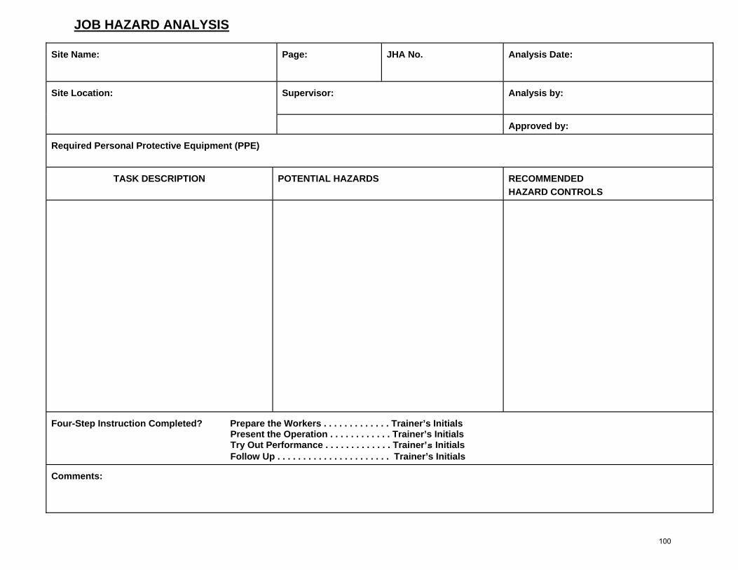
JOB HAZARD ANALYSIS
Site Name: Page: JHA No. Analysis Date:
Supervisor: Analysis by: Site Location:
Approved by:
Required Personal Protective Equipment (PPE)
TASK DESCRIPTION POTENTIAL HAZARDS RECOMMENDED HAZARD CONTROLS
Four-Step Instruction Completed? Prepare the Workers . . . . . . . . . . . . . Trainer’s Initials Present the Operation . . . . . . . . . . . . Trainer’s Initials Try Out Performance . . . . . . . . . . . . . Trainer’s Initials Follow Up . . . . . . . . . . . . . . . . . . . . . . Trainer’s Initials
Comments:
100

MIOSHA Fact Sheets
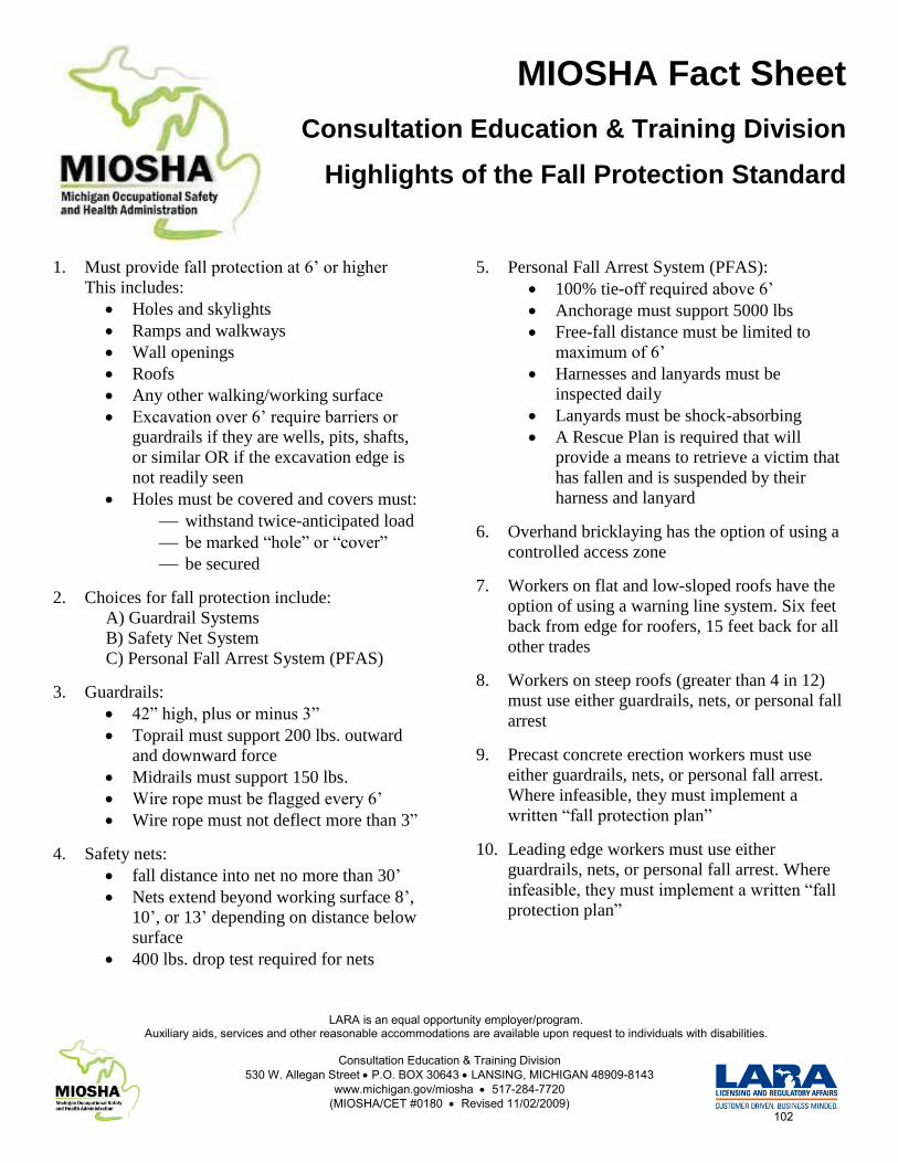
MIOSHA Fact Sheet
Consultation Education & Training Division
Highlights of the Fall Protection Standard
LARA is an equal opportunity employer/program.Auxiliary aids, services and other reasonable accommodations are available upon request to individuals with disabilities.
Consultation Education & Training Division530 W. Allegan Street P.O. BOX 30643 LANSING, MICHIGAN 48909-8143
www.michigan.gov/miosha 517-284-7720(MIOSHA/CET #0180 Revised 11/02/2009)
1. Must provide fall protection at 6’ or higher
This includes:
Holes and skylights
Ramps and walkways
Wall openings
Roofs
Any other walking/working surface
Excavation over 6’ require barriers or
guardrails if they are wells, pits, shafts,
or similar OR if the excavation edge is
not readily seen
Holes must be covered and covers must:
withstand twice-anticipated load
be marked “hole” or “cover”
be secured
2. Choices for fall protection include:
A) Guardrail Systems
B) Safety Net System
C) Personal Fall Arrest System (PFAS)
3. Guardrails:
42” high, plus or minus 3”
Toprail must support 200 lbs. outward
and downward force
Midrails must support 150 lbs.
Wire rope must be flagged every 6’
Wire rope must not deflect more than 3”
4. Safety nets:
fall distance into net no more than 30’
Nets extend beyond working surface 8’,
10’, or 13’ depending on distance below
surface
400 lbs. drop test required for nets
5. Personal Fall Arrest System (PFAS):
100% tie-off required above 6’
Anchorage must support 5000 lbs
Free-fall distance must be limited to
maximum of 6’
Harnesses and lanyards must be
inspected daily
Lanyards must be shock-absorbing
A Rescue Plan is required that will
provide a means to retrieve a victim that
has fallen and is suspended by their
harness and lanyard
6. Overhand bricklaying has the option of using a
controlled access zone
7. Workers on flat and low-sloped roofs have the
option of using a warning line system. Six feet
back from edge for roofers, 15 feet back for all
other trades
8. Workers on steep roofs (greater than 4 in 12)
must use either guardrails, nets, or personal fall
arrest
9. Precast concrete erection workers must use
either guardrails, nets, or personal fall arrest.
Where infeasible, they must implement a
written “fall protection plan”
10. Leading edge workers must use either
guardrails, nets, or personal fall arrest. Where
infeasible, they must implement a written “fall
protection plan”
102
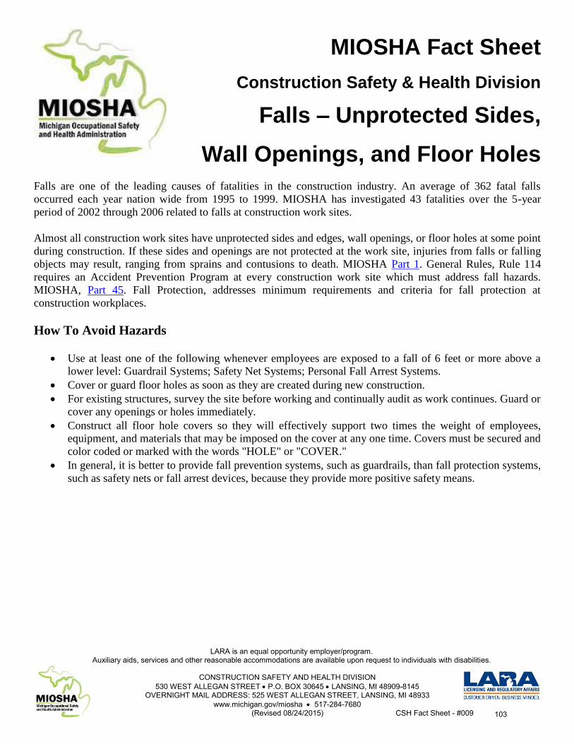
MIOSHA Fact Sheet
Construction Safety & Health Division
Falls – Unprotected Sides,
Wall Openings, and Floor Holes
LARA is an equal opportunity employer/program.Auxiliary aids, services and other reasonable accommodations are available upon request to individuals with disabilities.
CONSTRUCTION SAFETY AND HEALTH DIVISION530 WEST ALLEGAN STREET P.O. BOX 30645 LANSING, MI 48909-8145
OVERNIGHT MAIL ADDRESS: 525 WEST ALLEGAN STREET, LANSING, MI 48933www.michigan.gov/miosha 517-284-7680
(Revised 08/24/2015) CSH Fact Sheet - #009
Falls are one of the leading causes of fatalities in the construction industry. An average of 362 fatal falls
occurred each year nation wide from 1995 to 1999. MIOSHA has investigated 43 fatalities over the 5-year
period of 2002 through 2006 related to falls at construction work sites.
Almost all construction work sites have unprotected sides and edges, wall openings, or floor holes at some point
during construction. If these sides and openings are not protected at the work site, injuries from falls or falling
objects may result, ranging from sprains and contusions to death. MIOSHA Part 1. General Rules, Rule 114
requires an Accident Prevention Program at every construction work site which must address fall hazards.
MIOSHA, Part 45. Fall Protection, addresses minimum requirements and criteria for fall protection at
construction workplaces.
How To Avoid Hazards
Use at least one of the following whenever employees are exposed to a fall of 6 feet or more above a
lower level: Guardrail Systems; Safety Net Systems; Personal Fall Arrest Systems.
Cover or guard floor holes as soon as they are created during new construction.
For existing structures, survey the site before working and continually audit as work continues. Guard or
cover any openings or holes immediately.
Construct all floor hole covers so they will effectively support two times the weight of employees,
equipment, and materials that may be imposed on the cover at any one time. Covers must be secured and
color coded or marked with the words "HOLE" or "COVER."
In general, it is better to provide fall prevention systems, such as guardrails, than fall protection systems,
such as safety nets or fall arrest devices, because they provide more positive safety means.
103
Michigan Department of Licensing and Regulatory Affairs Michigan Occupational Safety & Health Administration
Consultation Education & Training Division 530 W. Allegan Steet, P.O. Box 30643
Lansing, Michigan 48909-8143
For further information or to request consultation, education and training services call (517) 284-7720
or visit our website at www.michigan.gov/miosha
www.michigan.gov/lara
LARA is an equal opportunity employer/program. Auxiliary aids, services and other reasonable accommodations are available upon request to individuals with disabilities.