Embed Size (px)
Citation preview
Residential/Commercial Generator Sets
Models:
8.5/12/18RES12/18TRES
Controller:Advanced Digital Control ADC-RES
TP-6792 4/13c
Installation
Engine exhaust from this product contains chemicalsknown to the State of California to cause cancer, birthdefects, or other reproductive harm.
WARNINGCalifornia Proposition 65
Product Identification Information
Generator Set Identification NumbersRecord the product identification numbers from thegenerator set nameplate(s).
Model Designation
Specification Number
Serial Number
Accessory Number Accessory Description
Engine IdentificationRecord the product identification information from theengine nameplate.
Manufacturer
Model Designation
Serial Number
Controller IdentificationRecord the controller description from the generator setoperation manual, spec sheet, or sales invoice.
Controller Description
Table of Contents
TP-6792 4/13 Table of Contents 3
Product Identification Information 2. . . . . . . . . . . . . . . . . . . . . . . . . . . . . . . . . . . . . . . . . . . . . . . . . . . . . . . . . . . . .
Safety Precautions and Instructions 5. . . . . . . . . . . . . . . . . . . . . . . . . . . . . . . . . . . . . . . . . . . . . . . . . . . . . . . . .
Introduction 9. . . . . . . . . . . . . . . . . . . . . . . . . . . . . . . . . . . . . . . . . . . . . . . . . . . . . . . . . . . . . . . . . . . . . . . . . . . . . . .
Service Assistance 12. . . . . . . . . . . . . . . . . . . . . . . . . . . . . . . . . . . . . . . . . . . . . . . . . . . . . . . . . . . . . . . . . . . . . . . . .
Section 1 Installation 13. . . . . . . . . . . . . . . . . . . . . . . . . . . . . . . . . . . . . . . . . . . . . . . . . . . . . . . . . . . . . . . . . . . . . .1.1 General 13. . . . . . . . . . . . . . . . . . . . . . . . . . . . . . . . . . . . . . . . . . . . . . . . . . . . . . . . . . . . . .1.2 Lifting 13. . . . . . . . . . . . . . . . . . . . . . . . . . . . . . . . . . . . . . . . . . . . . . . . . . . . . . . . . . . . . . . .1.3 Generator Set Inspection 13. . . . . . . . . . . . . . . . . . . . . . . . . . . . . . . . . . . . . . . . . . . . . . .1.4 Location and Mounting 13. . . . . . . . . . . . . . . . . . . . . . . . . . . . . . . . . . . . . . . . . . . . . . . . .
1.4.1 Exhaust Requirements 14. . . . . . . . . . . . . . . . . . . . . . . . . . . . . . . . . . . . . . . . .1.4.2 Air Requirements 14. . . . . . . . . . . . . . . . . . . . . . . . . . . . . . . . . . . . . . . . . . . . . .
1.5 Power Supply 15. . . . . . . . . . . . . . . . . . . . . . . . . . . . . . . . . . . . . . . . . . . . . . . . . . . . . . . . .1.6 Fuel Requirements 15. . . . . . . . . . . . . . . . . . . . . . . . . . . . . . . . . . . . . . . . . . . . . . . . . . . . .
1.6.1 Fuel Supply 15. . . . . . . . . . . . . . . . . . . . . . . . . . . . . . . . . . . . . . . . . . . . . . . . . . .1.6.2 Fuel Pipe Size 17. . . . . . . . . . . . . . . . . . . . . . . . . . . . . . . . . . . . . . . . . . . . . . . . .
1.7 Fuel Conversion 17. . . . . . . . . . . . . . . . . . . . . . . . . . . . . . . . . . . . . . . . . . . . . . . . . . . . . . .1.7.1 Fuel Conversion, 8.5/12RES 18. . . . . . . . . . . . . . . . . . . . . . . . . . . . . . . . . . . .1.7.2 Fuel Conversion, 18RES 19. . . . . . . . . . . . . . . . . . . . . . . . . . . . . . . . . . . . . . .
1.8 Electrical Connections 21. . . . . . . . . . . . . . . . . . . . . . . . . . . . . . . . . . . . . . . . . . . . . . . . . .1.8.1 Field Connections 21. . . . . . . . . . . . . . . . . . . . . . . . . . . . . . . . . . . . . . . . . . . . .1.8.2 Remote Start Connection 24. . . . . . . . . . . . . . . . . . . . . . . . . . . . . . . . . . . . . . .1.8.3 Grounding 24. . . . . . . . . . . . . . . . . . . . . . . . . . . . . . . . . . . . . . . . . . . . . . . . . . . .1.8.4 Battery Charger 24. . . . . . . . . . . . . . . . . . . . . . . . . . . . . . . . . . . . . . . . . . . . . . .
1.9 Battery 25. . . . . . . . . . . . . . . . . . . . . . . . . . . . . . . . . . . . . . . . . . . . . . . . . . . . . . . . . . . . . . .1.10 Accessories 26. . . . . . . . . . . . . . . . . . . . . . . . . . . . . . . . . . . . . . . . . . . . . . . . . . . . . . . . . . .
1.10.1 Common Fault and Auxiliary Run Relay Board 26. . . . . . . . . . . . . . . . . . . . .1.10.2 Carburetor Heater 27. . . . . . . . . . . . . . . . . . . . . . . . . . . . . . . . . . . . . . . . . . . . .
1.11 Prestart Installation Check 29. . . . . . . . . . . . . . . . . . . . . . . . . . . . . . . . . . . . . . . . . . . . . .1.12 Startup Notification 29. . . . . . . . . . . . . . . . . . . . . . . . . . . . . . . . . . . . . . . . . . . . . . . . . . . . .1.13 Controller Configuration 29. . . . . . . . . . . . . . . . . . . . . . . . . . . . . . . . . . . . . . . . . . . . . . . .
1.13.1 System Parameters 29. . . . . . . . . . . . . . . . . . . . . . . . . . . . . . . . . . . . . . . . . . . .1.13.2 Application Code Version 30. . . . . . . . . . . . . . . . . . . . . . . . . . . . . . . . . . . . . . .
1.14 Voltage and Frequency Adjustments 32. . . . . . . . . . . . . . . . . . . . . . . . . . . . . . . . . . . . .1.14.1 Voltage Adjustment 32. . . . . . . . . . . . . . . . . . . . . . . . . . . . . . . . . . . . . . . . . . . .1.14.2 Frequency Adjustment 33. . . . . . . . . . . . . . . . . . . . . . . . . . . . . . . . . . . . . . . . .
Section 2 Dimension Drawings and Wiring Diagrams 37. . . . . . . . . . . . . . . . . . . . . . . . . . . . . . . . . . . . . . . . .
Appendix A Abbreviations 57. . . . . . . . . . . . . . . . . . . . . . . . . . . . . . . . . . . . . . . . . . . . . . . . . . . . . . . . . . . . . . . .

TP-6792 4/134
Notes
TP-6792 4/13 5Safety Precautions and Instructions
Safety Precautions and Instructions
IMPORTANTSAFETY INSTRUCTIONS.Electromechanical equipment,including generator sets, transferswitches, switchgear, and accessories,can cause bodily harm and poselife-threatening danger whenimproperly installed, operated, ormaintained. To prevent accidents beaware of potential dangers and actsafely. Read and follow all safetyprecautions and instructions. SAVETHESE INSTRUCTIONS.
Thismanual has several types of safetyprecautions and instructions: Danger,Warning, Caution, and Notice.
DANGER
Danger indicates the presence of ahazard that will cause severepersonal injury, death, orsubstantialproperty damage.
WARNING
Warning indicates the presence of ahazard that can cause severepersonal injury, death, orsubstantialproperty damage.
CAUTION
Caution indicates the presence of ahazard that will or can cause minorpersonal injury or property damage.
NOTICENotice communicates installation,operation, or maintenance informationthat is safety related but not hazardrelated.
Safety decals affixed to the equipmentin prominent places alert the operatoror service technician to potentialhazards and explain how to act safely.The decals are shown throughout thispublication to improve operatorrecognition. Replace missing ordamaged decals.
Accidental Starting
Accidental starting.Can cause severe injury or death.
Disconnect the battery cables beforeworking on the generator set.Remove the negative (--) lead firstwhen disconnecting the battery.Reconnect the negative (--) lead lastwhen reconnecting the battery.
WARNING
Disabling the generator set.Accidental starting can causesevere injury or death. Beforeworking on the generator set orconnected equipment, disable thegenerator set as follows: (1) Move thegenerator set master switch to the OFFposition. (2) Disconnect the power tothe battery charger. (3) Remove thebattery cables, negative (--) lead first.Reconnect the negative (--) lead lastwhen reconnecting the battery. Followthese precautions to prevent starting ofthe generator set by an automatictransfer switch, remote start/stopswitch, or engine start command fromaremote computer.
Battery
Sulfuric acid in batteries.Can cause severe injury or death.
Wear protective goggles andclothing. Battery acid may causeblindness and burn skin.
WARNING
Explosion.Can cause severe injury or death.Relays in the battery chargercause arcs or sparks.
Locate the battery in a well-ventilatedarea. Isolate the battery charger fromexplosive fumes.
WARNING
Battery electrolyte is a dilutedsulfuric acid. Battery acid cancausesevere injury or death. Battery acidcan cause blindness and burn skin.Always wear splashproof safetygoggles, rubber gloves, and bootswhen servicing the battery. Do notopen a sealed battery or mutilate thebattery case. If battery acid splashes inthe eyes or on the skin, immediatelyflush the affected area for 15 minuteswith large quantities of clean water.Seek immediatemedical aid in the caseof eye contact. Never add acid to abattery after placing the battery inservice, as this may result in hazardousspattering of battery acid.
Battery acid cleanup. Battery acidcan cause severe injury or death.Battery acid is electrically conductiveand corrosive. Add 500 g (1 lb.) ofbicarbonate of soda (baking soda) to acontainer with 4 L (1 gal.) of water andmix the neutralizing solution. Pour theneutralizing solution on the spilledbattery acid and continue to add theneutralizing solution to the spilledbattery acid until all evidence of achemical reaction (foaming) hasceased. Flush the resulting liquid withwater and dry the area.
TP-6792 4/136 Safety Precautions and Instructions
Battery gases. Explosion can causesevere injury or death. Battery gasescan cause an explosion. Do not smokeor permit flames or sparks to occur neara battery at any time, particularly whenit is charging. Do not dispose of abattery in a fire. To prevent burns andsparks that could cause an explosion,avoid touching the battery terminalswith tools or other metal objects.Remove all jewelry before servicing theequipment. Discharge static electricityfrom your body before touchingbatteries by first touching a groundedmetal surface away from thebattery. Toavoid sparks, do not disturb the batterycharger connections while the batteryis charging. Always turn the batterycharger off before disconnecting thebattery connections. Ventilate thecompartments containing batteries toprevent accumulation of explosivegases.
Battery short circuits. Explosioncan cause severe injury or death.Short circuits can cause bodily injuryand/or equipment damage.Disconnect the battery beforegenerator set installation ormaintenance. Remove all jewelrybefore servicing the equipment. Usetools with insulated handles. Removethe negative (--) lead first whendisconnecting the battery. Reconnectthe negative (--) lead last whenreconnecting the battery. Neverconnect the negative (--) battery cableto the positive (+) connection terminalof the starter solenoid. Do not test thebattery condition by shorting theterminals together.
Engine Backfire/FlashFire
Fire.Can cause severe injury or death.
Do not smoke or permit flames orsparks near fuels or the fuel system.
WARNING
Servicing the air cleaner. A suddenbackfire can cause severe injury ordeath. Do not operate the generatorset with the air cleaner removed.
Servicing the fuel system. A flashfire cancausesevere injuryor death.Do not smoke or permit flames orsparks near the carburetor, fuel line,fuel filter, fuel pump, or other potentialsources of spilled fuels or fuel vapors.Catch fuels in an approved containerwhen removing the fuel line orcarburetor.
Combustible materials. A fire cancause severe injury or death.Generator set engine fuels and fuelvapors are flammable and explosive.Handle these materials carefully tominimize the risk of fire or explosion.Equip the compartment or nearby areawith a fully charged fire extinguisher.Select a fire extinguisher rated ABC orBC for electrical fires or asrecommended by the local fire code oran authorized agency. Train allpersonnel on fire extinguisheroperation and fire preventionprocedures.
Exhaust System
Carbon monoxide.Can cause severe nausea,fainting, or death.
The exhaust system must beleakproof and routinely inspected.
WARNING
Generator set operation. Carbonmonoxide can cause severe nausea,fainting, or death. Carbon monoxideis an odorless, colorless, tasteless,nonirritating gas that can cause death ifinhaled for even a short time. Avoidbreathing exhaust fumeswhenworkingon or near the generator set. Neveroperate the generator set inside abuilding. Never operate the generatorset where exhaust gas could seepinside or be drawn into a potentiallyoccupied building through windows, airintake vents, or other openings.
Carbon monoxide symptoms.Carbon monoxide can cause severenausea, fainting, or death. Carbonmonoxide is a poisonous gas present inexhaust gases. Carbonmonoxide is anodorless, colorless, tasteless,nonirritating gas that can cause death ifinhaled for even a short time. Carbonmonoxide poisoning symptoms includebut are not limited to the following:D Light-headedness, dizzinessD Physical fatigue, weakness injoints and muscles
D Sleepiness, mental fatigue,inability to concentrateor speak clearly, blurred vision
D Stomachache, vomiting, nauseaIf experiencing any of these symptomsand carbon monoxide poisoning ispossible, seek fresh air immediatelyand remain active. Do not sit, lie down,or fall asleep. Alert others to thepossibility of carbon monoxidepoisoning. Seek medical attention ifthe condition of affected persons doesnot improvewithinminutes of breathingfresh air.
Fuel System
Explosive fuel vapors.Can cause severe injury or death.
Use extreme care when handling,storing, and using fuels.
WARNING
Gas fuel leaks. Explosive fuelvapors can cause severe injury ordeath. Fuel leakage can cause anexplosion. Check the LP vapor gas ornatural gas fuel system for leakage byusing a soap and water solution withthe fuel system test pressurized to6--8 ounces per square inch(10--14 inches water column). Do notuse a soap solution containing eitherammonia or chlorine because bothprevent bubble formation. A successfultest depends on the ability of thesolution to bubble.
TP-6792 4/13 7Safety Precautions and Instructions
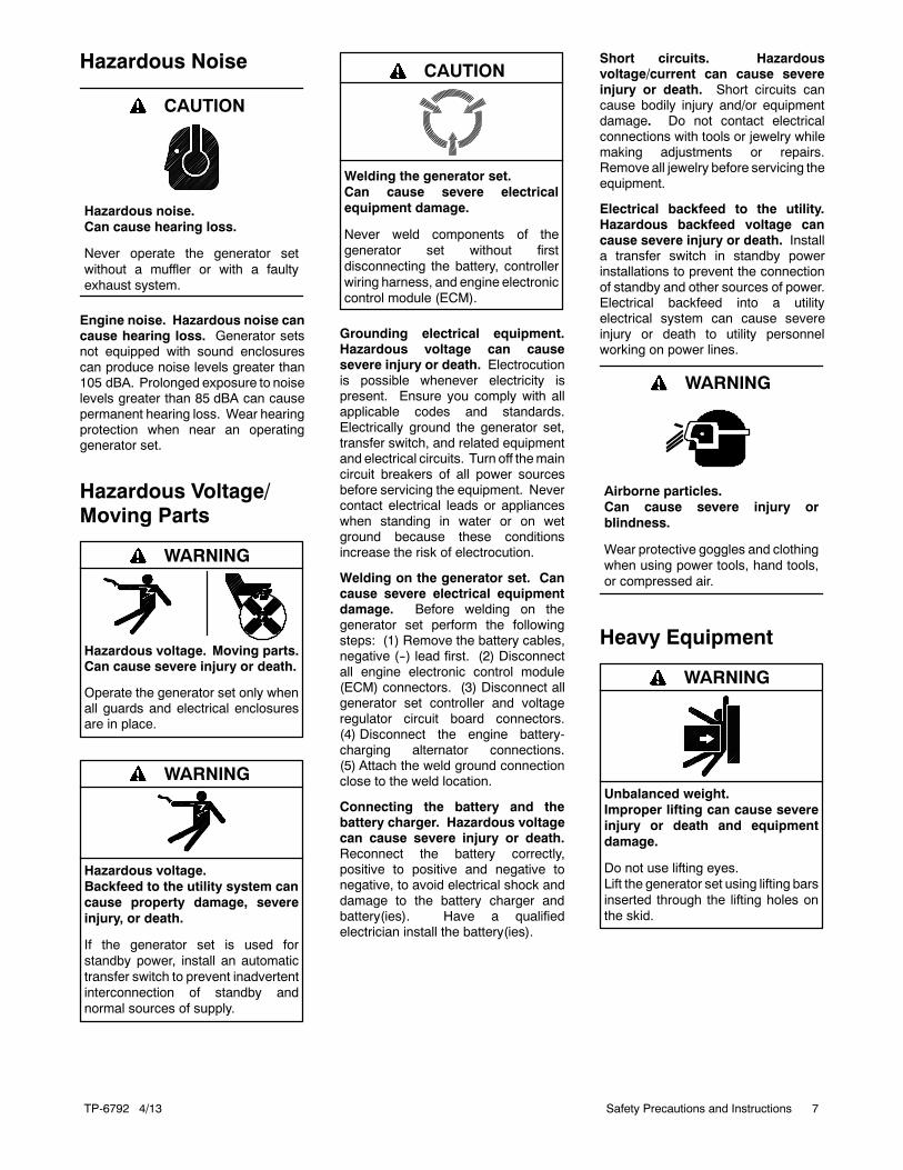
Hazardous Noise
Hazardous noise.Can cause hearing loss.
Never operate the generator setwithout a muffler or with a faultyexhaust system.
CAUTION
Engine noise. Hazardous noise cancause hearing loss. Generator setsnot equipped with sound enclosurescan produce noise levels greater than105 dBA. Prolonged exposure to noiselevels greater than 85 dBA can causepermanent hearing loss. Wear hearingprotection when near an operatinggenerator set.
Hazardous Voltage/Moving Parts
Hazardous voltage.Can cause severe injury or death.
Operate the generator set only whenall guards and electrical enclosuresare in place.
Moving parts.
WARNING
Hazardous voltage.Backfeed to the utility system cancause property damage, severeinjury, or death.
If the generator set is used forstandby power, install an automatictransfer switch to prevent inadvertentinterconnection of standby andnormal sources of supply.
WARNING
Welding the generator set.Can cause severe electricalequipment damage.
Never weld components of thegenerator set without firstdisconnecting the battery, controllerwiring harness, and engine electroniccontrol module (ECM).
CAUTION
Grounding electrical equipment.Hazardous voltage can causesevere injury or death. Electrocutionis possible whenever electricity ispresent. Ensure you comply with allapplicable codes and standards.Electrically ground the generator set,transfer switch, and related equipmentand electrical circuits. Turn off themaincircuit breakers of all power sourcesbefore servicing the equipment. Nevercontact electrical leads or applianceswhen standing in water or on wetground because these conditionsincrease the risk of electrocution.
Welding on the generator set. Cancause severe electrical equipmentdamage. Before welding on thegenerator set perform the followingsteps: (1) Remove the battery cables,negative (--) lead first. (2) Disconnectall engine electronic control module(ECM) connectors. (3) Disconnect allgenerator set controller and voltageregulator circuit board connectors.(4) Disconnect the engine battery-charging alternator connections.(5) Attach the weld ground connectionclose to the weld location.
Connecting the battery and thebattery charger. Hazardous voltagecan cause severe injury or death.Reconnect the battery correctly,positive to positive and negative tonegative, to avoid electrical shock anddamage to the battery charger andbattery(ies). Have a qualifiedelectrician install the battery(ies).
Short circuits. Hazardousvoltage/current can cause severeinjury or death. Short circuits cancause bodily injury and/or equipmentdamage. Do not contact electricalconnections with tools or jewelry whilemaking adjustments or repairs.Remove all jewelry before servicing theequipment.
Electrical backfeed to the utility.Hazardous backfeed voltage cancause severe injury or death. Installa transfer switch in standby powerinstallations to prevent the connectionof standby and other sources of power.Electrical backfeed into a utilityelectrical system can cause severeinjury or death to utility personnelworking on power lines.
Airborne particles.Can cause severe injury orblindness.
Wear protective goggles and clothingwhen using power tools, hand tools,or compressed air.
WARNING
Heavy Equipment
Unbalanced weight.Improper lifting can cause severeinjury or death and equipmentdamage.
Do not use lifting eyes.Lift the generator set using lifting barsinserted through the lifting holes onthe skid.
WARNING
TP-6792 4/138 Safety Precautions and Instructions
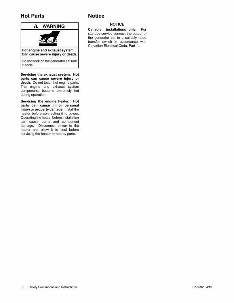
Hot Parts
Hot engine and exhaust system.Can cause severe injury or death.
Do not work on the generator set untilit cools.
WARNING
Servicing the exhaust system. Hotparts can cause severe injury ordeath. Do not touch hot engine parts.The engine and exhaust systemcomponents become extremely hotduring operation.
Servicing the engine heater. Hotparts can cause minor personalinjury or property damage. Install theheater before connecting it to power.Operating the heater before installationcan cause burns and componentdamage. Disconnect power to theheater and allow it to cool beforeservicing the heater or nearby parts.
NoticeNOTICE
Canadian installations only. Forstandby service connect the output ofthe generator set to a suitably ratedtransfer switch in accordance withCanadian Electrical Code, Part 1.
TP-6792 4/13 9
Introduction
This manual provides installation instructions forResidential/Commercial model generator sets listed onthe front cover. Refer toTP-6515,OperationManual, forgenerator set operation and maintenance instructions.
The generator set is approved for use in stationaryapplications in locations served by a reliable utilitypower source.
Have an authorized distributor/dealer install thegenerator set outdoors according to the instructions inthismanual. The generator set installationmust complywith the National Electrical Code (NEC) and local coderequirements. Do not install this generator set indoors.
Information in this publication represents data availableat the time of print. Kohler Co. reserves the right tochange this publication and the products representedwithout notice and without any obligation or liabilitywhatsoever.
Read this manual and carefully follow all proceduresand safety precautions to ensure proper equipmentoperation and to avoid bodily injury. Readand follow theSafety Precautions and Instructions section at thebeginning of this manual.
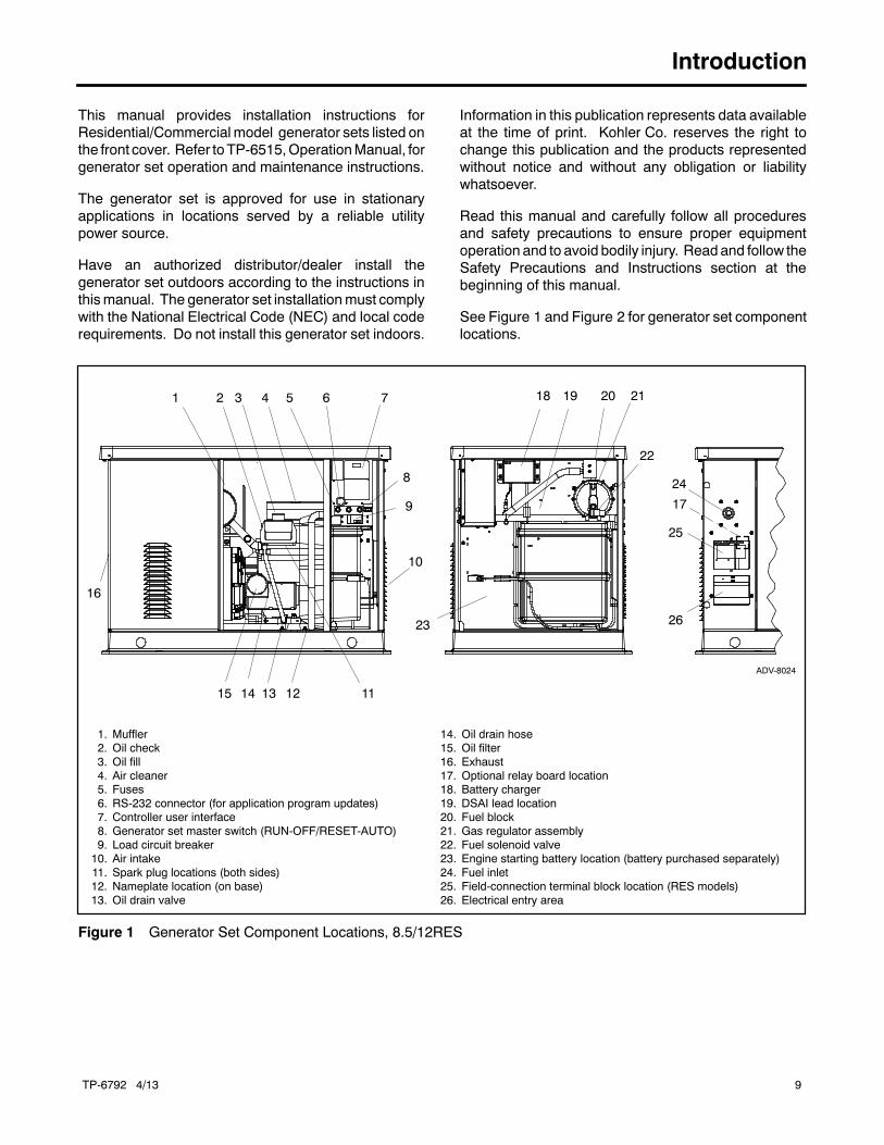
See Figure 1 and Figure 2 for generator set componentlocations.
ADV-8024
1. Muffler2. Oil check3. Oil fill4. Air cleaner5. Fuses6. RS-232 connector (for application program updates)7. Controller user interface8. Generator set master switch (RUN-OFF/RESET-AUTO)9. Load circuit breaker10. Air intake11. Spark plug locations (both sides)12. Nameplate location (on base)13. Oil drain valve
14. Oil drain hose15. Oil filter16. Exhaust17. Optional relay board location18. Battery charger19. DSAI lead location20. Fuel block21. Gas regulator assembly22. Fuel solenoid valve23. Engine starting battery location (battery purchased separately)24. Fuel inlet25. Field-connection terminal block location (RES models)26. Electrical entry area
75 61 2 3 4
15 13
23
9
8
18 21
22
24
10
16
11
25
19 20
17
14
26
12
Figure 1 Generator Set Component Locations, 8.5/12RES
TP-6792 4/1310
1 2 54 22
16
63
13 27
17
21
1415
24
ADV-8025
10
2826
9
19 23
29
Control detail8
11
7
12
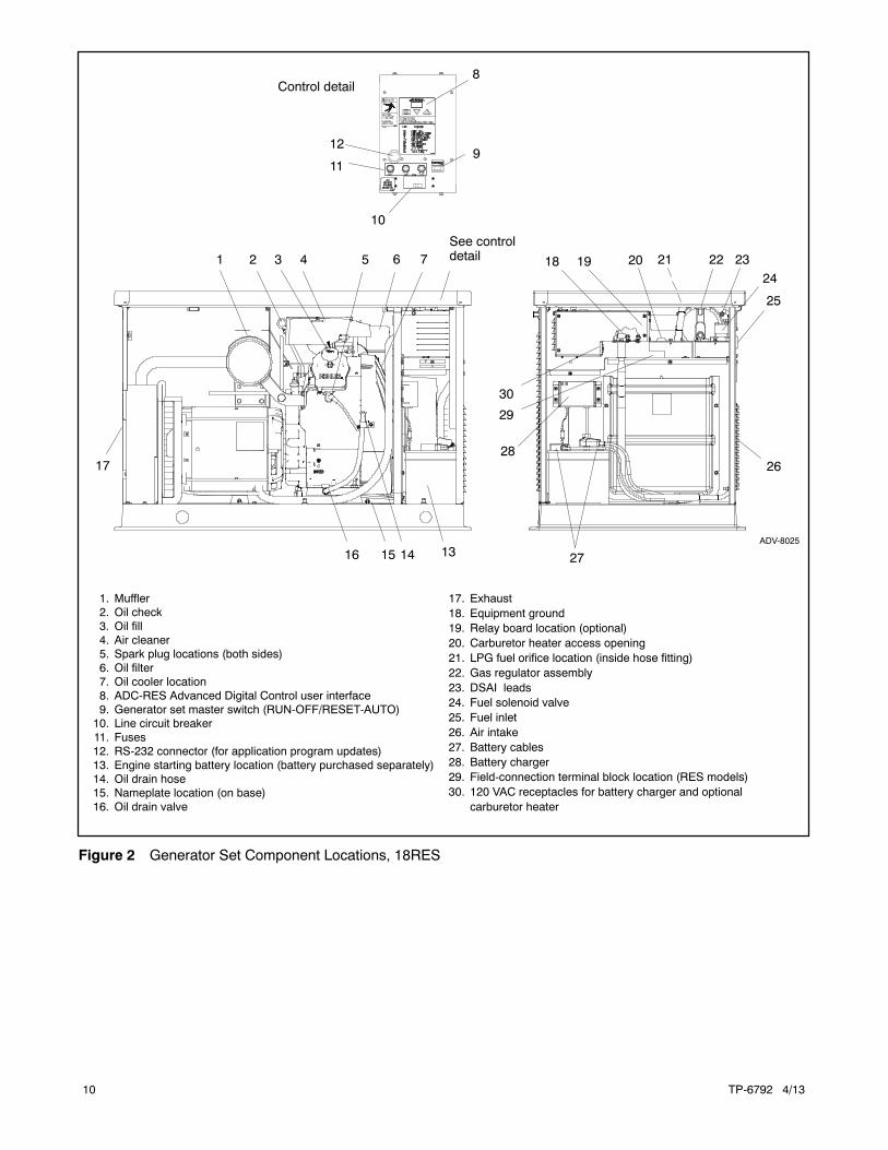
1. Muffler2. Oil check3. Oil fill4. Air cleaner5. Spark plug locations (both sides)6. Oil filter7. Oil cooler location8. ADC-RES Advanced Digital Control user interface9. Generator set master switch (RUN-OFF/RESET-AUTO)10. Line circuit breaker11. Fuses12. RS-232 connector (for application program updates)13. Engine starting battery location (battery purchased separately)14. Oil drain hose15. Nameplate location (on base)16. Oil drain valve
17. Exhaust18. Equipment ground19. Relay board location (optional)20. Carburetor heater access opening21. LPG fuel orifice location (inside hose fitting)22. Gas regulator assembly23. DSAI leads24. Fuel solenoid valve25. Fuel inlet26. Air intake27. Battery cables28. Battery charger29. Field-connection terminal block location (RES models)30. 120 VAC receptacles for battery charger and optional
carburetor heater
See controldetail 20
30
25
18
Figure 2 Generator Set Component Locations, 18RES
TP-6792 4/13 11
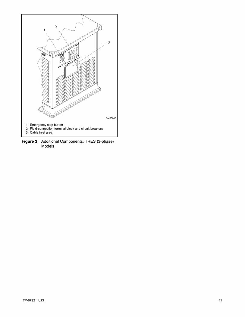
1
GM66010
1. Emergency stop button2. Field-connection terminal block and circuit breakers3. Cable inlet area
2
3
Figure 3 Additional Components, TRES (3-phase)Models
TP-6792 4/1312
Service Assistance
For professional advice on generator set powerrequirementsandconscientiousservice, pleasecontactyour nearest Kohler distributor or dealer.
D Consult the Yellow Pages under the headingGenerators—Electric.
D Visit the Kohler Power Systems website atKOHLERPower.com.
D Look at the labels and decals on your Kohler productor review the appropriate literature or documentsincluded with the product.
D Call toll free in the US and Canada 1-800-544-2444.
D Outside theUSandCanada, call the nearest regionaloffice.
Headquarters Europe, Middle East, Africa(EMEA)Kohler Power Systems3 rue de Brennus93200 Saint DenisFrancePhone: (33) 1 49 178300Fax: (33) 1 49 178301
Asia PacificPower Systems Asia Pacific Regional OfficeSingapore, Republic of SingaporePhone: (65) 6264-6422Fax: (65) 6264-6455
ChinaNorth China Regional Office, BeijingPhone: (86) 10 6518 7950
(86) 10 6518 7951(86) 10 6518 7952
Fax: (86) 10 6518 7955
East China Regional Office, ShanghaiPhone: (86) 21 6288 0500Fax: (86) 21 6288 0550
India, Bangladesh, Sri LankaIndia Regional OfficeBangalore, IndiaPhone: (91) 80 3366208
(91) 80 3366231Fax: (91) 80 3315972
Japan, KoreaNorth Asia Regional OfficeTokyo, JapanPhone: (813) 3440-4515Fax: (813) 3440-2727
Latin AmericaLatin America Regional OfficeLakeland, Florida, USAPhone: (863) 619-7568Fax: (863) 701-7131
TP-6792 4/13 13Section 1 Installation
Section 1 Installation
1.1 General
Have an authorized distributor/dealer install thegenerator set outdoors according to the instructions inthis manual. Do not install this generator set indoors.
Use the specifications provided here only in the initialplanning. Use the generator set and transfer switchdimension drawingsandwiring diagrams for installation.See Section 2 for the generator set dimension drawingsand wiring diagrams.
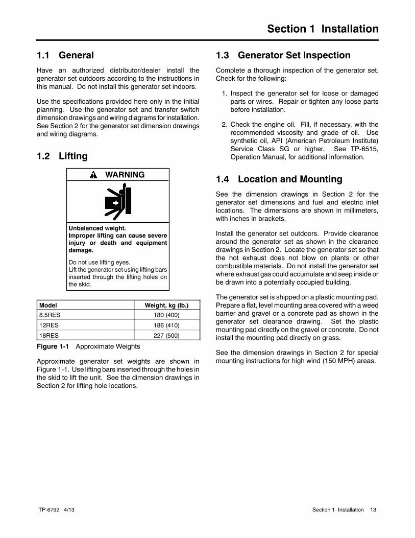
1.2 Lifting
Unbalanced weight.Improper lifting can cause severeinjury or death and equipmentdamage.
Do not use lifting eyes.Lift the generator set using lifting barsinserted through the lifting holes onthe skid.
WARNING
Model Weight, kg (lb.)
8.5RES 180 (400)
12RES 186 (410)
18RES 227 (500)
Figure 1-1 Approximate Weights
Approximate generator set weights are shown inFigure 1-1. Use lifting bars inserted through the holes inthe skid to lift the unit. See the dimension drawings inSection 2 for lifting hole locations.
1.3 Generator Set Inspection
Complete a thorough inspection of the generator set.Check for the following:
1. Inspect the generator set for loose or damagedparts or wires. Repair or tighten any loose partsbefore installation.
2. Check the engine oil. Fill, if necessary, with therecommended viscosity and grade of oil. Usesynthetic oil, API (American Petroleum Institute)Service Class SG or higher. See TP-6515,Operation Manual, for additional information.
1.4 Location and Mounting
See the dimension drawings in Section 2 for thegenerator set dimensions and fuel and electric inletlocations. The dimensions are shown in millimeters,with inches in brackets.
Install the generator set outdoors. Provide clearancearound the generator set as shown in the clearancedrawings in Section 2. Locate the generator set so thatthe hot exhaust does not blow on plants or othercombustible materials. Do not install the generator setwhereexhaust gas could accumulate andseep insideorbe drawn into a potentially occupied building.
The generator set is shipped on a plastic mounting pad.Prepare a flat, level mounting area covered with a weedbarrier and gravel or a concrete pad as shown in thegenerator set clearance drawing. Set the plasticmounting pad directly on the gravel or concrete. Do notinstall the mounting pad directly on grass.
See the dimension drawings in Section 2 for specialmounting instructions for high wind (150 MPH) areas.
TP-6792 4/1314 Section 1 Installation
1.4.1 Exhaust Requirements
Carbon monoxide.Can cause severe nausea,fainting, or death.
The exhaust system must beleakproof and routinely inspected.
WARNING
Generator set operation. Carbon monoxide can causesevere nausea, fainting, or death. Carbon monoxide is anodorless, colorless, tasteless, nonirritating gas that can causedeath if inhaled for even a short time. Avoid breathing exhaustfumes when working on or near the generator set. Neveroperate the generator set inside a building. Never operate thegenerator set where exhaust gas could seep inside or bedrawn into a potentially occupied building throughwindows, airintake vents, or other openings.
The exhaust system is complete for generator setsinstalled outdoors. Do not install this generator setindoors.
Figure 1-2 gives the exhaust flow and temperature atrated load. The engine exhaust mixes with thegenerator set cooling air at the exhaust end of theenclosure. Mount the generator set so that the hotexhaust does not blow on plants or other combustiblematerials. Maintain the clearances shown in thedimension drawings in Section 2.
Exhaust System 60 Hz 50 Hz
Exhaust flow at rated kW,m3/min. (cfm)
8.5 RES 3.3 (115) 2.7 (96)
12 RES 3.8 (135) 3.2 (113)
18RES 5.3 (187) 4.4 (155)
Exhaust gas exiting the enclosureat rated kW, _C (_F) 216 (420)
Figure 1-2 Exhaust Flow and Temperature
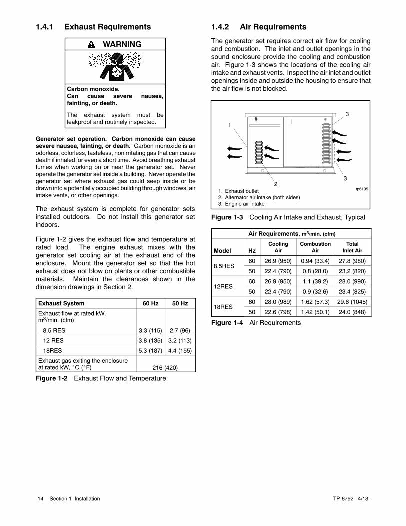
1.4.2 Air Requirements
The generator set requires correct air flow for coolingand combustion. The inlet and outlet openings in thesound enclosure provide the cooling and combustionair. Figure 1-3 shows the locations of the cooling airintake and exhaust vents. Inspect the air inlet and outletopenings inside and outside the housing to ensure thatthe air flow is not blocked.
tp61952
1. Exhaust outlet2. Alternator air intake (both sides)3. Engine air intake
3
1
3
Figure 1-3 Cooling Air Intake and Exhaust, Typical
Air Requirements, m3/min. (cfm)
Model HzCoolingAir
CombustionAir
TotalInlet Air
8.5RES60 26.9 (950) 0.94 (33.4) 27.8 (980)
50 22.4 (790) 0.8 (28.0) 23.2 (820)
12RES60 26.9 (950) 1.1 (39.2) 28.0 (990)
50 22.4 (790) 0.9 (32.6) 23.4 (825)
18RES60 28.0 (989) 1.62 (57.3) 29.6 (1045)
50 22.6 (798) 1.42 (50.1) 24.0 (848)
Figure 1-4 Air Requirements
TP-6792 4/13 15Section 1 Installation
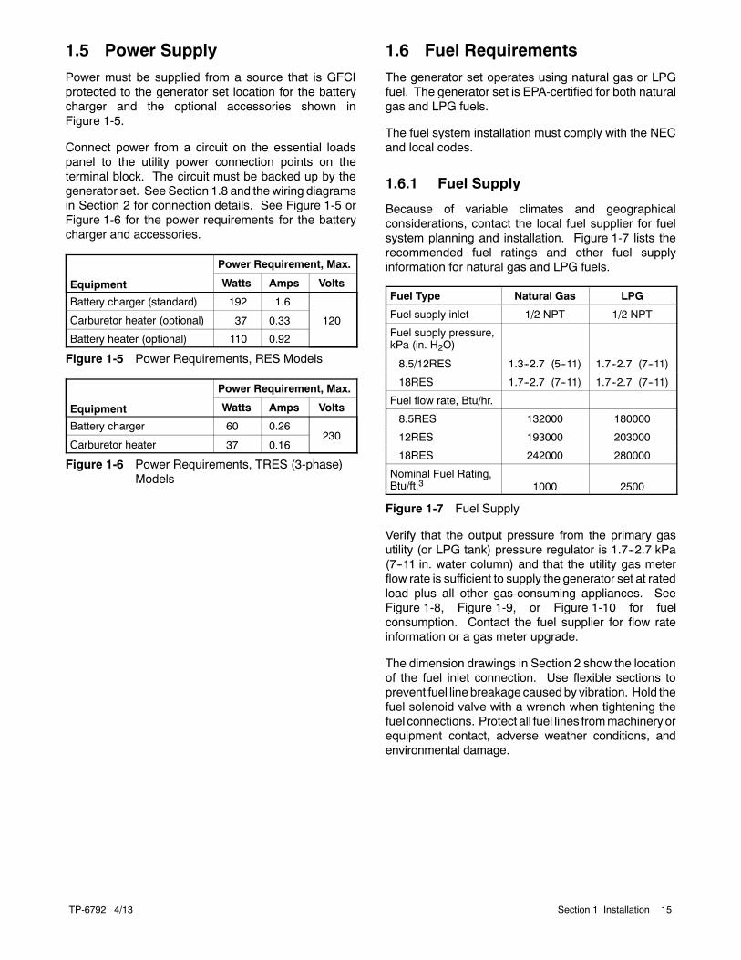
1.5 Power Supply
Power must be supplied from a source that is GFCIprotected to the generator set location for the batterycharger and the optional accessories shown inFigure 1-5.
Connect power from a circuit on the essential loadspanel to the utility power connection points on theterminal block. The circuit must be backed up by thegenerator set. See Section 1.8 and the wiring diagramsin Section 2 for connection details. See Figure 1-5 orFigure 1-6 for the power requirements for the batterycharger and accessories.
Equipment
Power Requirement, Max.
Watts Amps Volts
Battery charger (standard) 192 1.6
120Carburetor heater (optional) 37 0.33
Battery heater (optional) 110 0.92
Figure 1-5 Power Requirements, RES Models
Equipment
Power Requirement, Max.
Watts Amps Volts
Battery charger 60 0.26230
Carburetor heater 37 0.16
Figure 1-6 Power Requirements, TRES (3-phase)Models
1.6 Fuel Requirements
The generator set operates using natural gas or LPGfuel. The generator set is EPA-certified for both naturalgas and LPG fuels.
The fuel system installation must comply with the NECand local codes.
1.6.1 Fuel Supply
Because of variable climates and geographicalconsiderations, contact the local fuel supplier for fuelsystem planning and installation. Figure 1-7 lists therecommended fuel ratings and other fuel supplyinformation for natural gas and LPG fuels.
Fuel Type Natural Gas LPG
Fuel supply inlet 1/2 NPT 1/2 NPT
Fuel supply pressure,kPa (in. H2O)
8.5/12RES 1.3--2.7 (5--11) 1.7--2.7 (7--11)
18RES 1.7--2.7 (7--11) 1.7--2.7 (7--11)
Fuel flow rate, Btu/hr.
8.5RES 132000 180000
12RES 193000 203000
18RES 242000 280000
Nominal Fuel Rating,Btu/ft.3 1000 2500
Figure 1-7 Fuel Supply
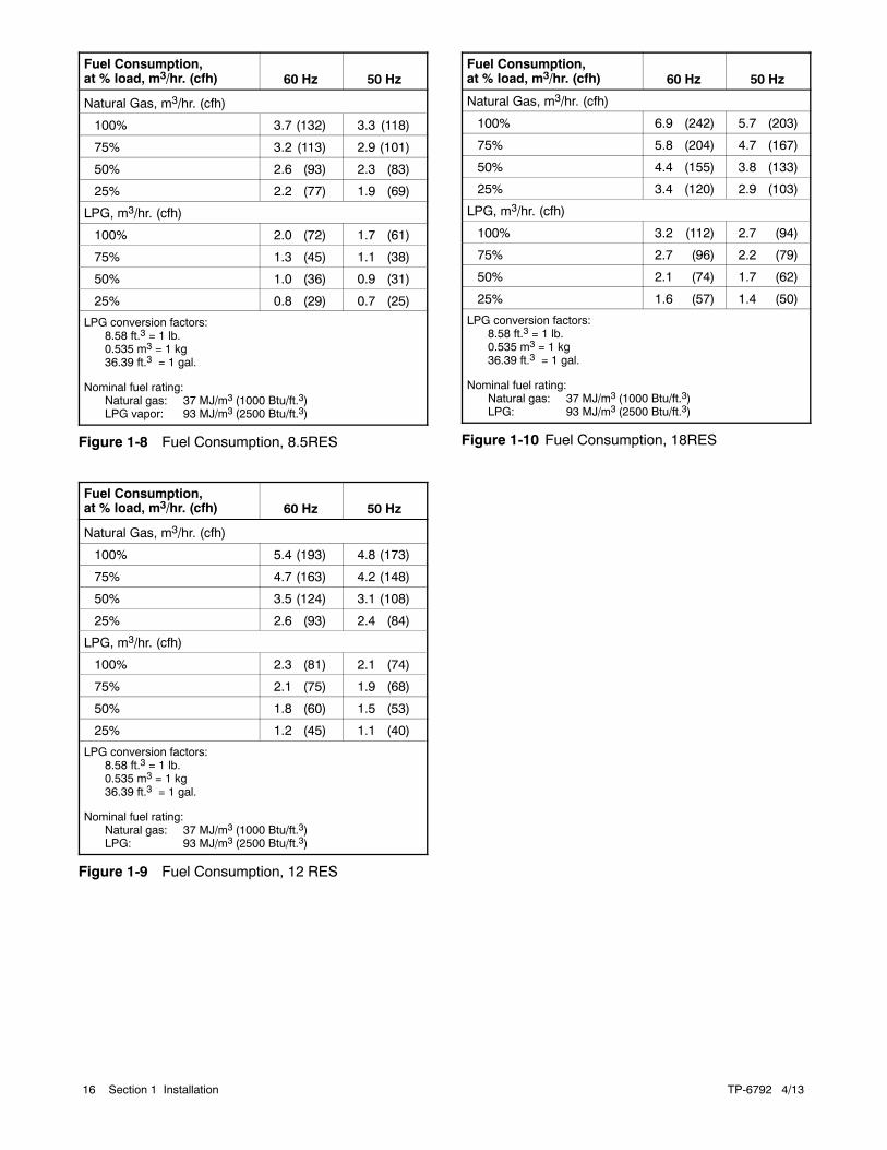
Verify that the output pressure from the primary gasutility (or LPG tank) pressure regulator is 1.7--2.7 kPa(7--11 in. water column) and that the utility gas meterflow rate is sufficient to supply the generator set at ratedload plus all other gas-consuming appliances. SeeFigure 1-8, Figure 1-9, or Figure 1-10 for fuelconsumption. Contact the fuel supplier for flow rateinformation or a gas meter upgrade.
The dimension drawings in Section 2 show the locationof the fuel inlet connection. Use flexible sections toprevent fuel line breakage causedby vibration. Hold thefuel solenoid valve with a wrench when tightening thefuel connections. Protect all fuel lines frommachineryorequipment contact, adverse weather conditions, andenvironmental damage.
TP-6792 4/1316 Section 1 Installation
Fuel Consumption,at % load, m3/hr. (cfh) 60 Hz 50 Hz
Natural Gas, m3/hr. (cfh)
100% 3.7 (132) 3.3 (118)
75% 3.2 (113) 2.9 (101)
50% 2.6 (93) 2.3 (83)
25% 2.2 (77) 1.9 (69)
LPG, m3/hr. (cfh)
100% 2.0 (72) 1.7 (61)
75% 1.3 (45) 1.1 (38)
50% 1.0 (36) 0.9 (31)
25% 0.8 (29) 0.7 (25)
LPG conversion factors:8.58 ft.3 = 1 lb.0.535 m3 = 1 kg36.39 ft.3 = 1 gal.
Nominal fuel rating:Natural gas: 37 MJ/m3 (1000 Btu/ft.3)LPG vapor: 93 MJ/m3 (2500 Btu/ft.3)
Figure 1-8 Fuel Consumption, 8.5RES
Fuel Consumption,at % load, m3/hr. (cfh) 60 Hz 50 Hz
Natural Gas, m3/hr. (cfh)
100% 5.4 (193) 4.8 (173)
75% 4.7 (163) 4.2 (148)
50% 3.5 (124) 3.1 (108)
25% 2.6 (93) 2.4 (84)
LPG, m3/hr. (cfh)
100% 2.3 (81) 2.1 (74)
75% 2.1 (75) 1.9 (68)
50% 1.8 (60) 1.5 (53)
25% 1.2 (45) 1.1 (40)
LPG conversion factors:8.58 ft.3 = 1 lb.0.535 m3 = 1 kg36.39 ft.3 = 1 gal.
Nominal fuel rating:Natural gas: 37 MJ/m3 (1000 Btu/ft.3)LPG: 93 MJ/m3 (2500 Btu/ft.3)
Figure 1-9 Fuel Consumption, 12 RES
Fuel Consumption,at % load, m3/hr. (cfh) 60 Hz 50 Hz
Natural Gas, m3/hr. (cfh)
100% 6.9 (242) 5.7 (203)
75% 5.8 (204) 4.7 (167)
50% 4.4 (155) 3.8 (133)
25% 3.4 (120) 2.9 (103)
LPG, m3/hr. (cfh)
100% 3.2 (112) 2.7 (94)
75% 2.7 (96) 2.2 (79)
50% 2.1 (74) 1.7 (62)
25% 1.6 (57) 1.4 (50)
LPG conversion factors:8.58 ft.3 = 1 lb.0.535 m3 = 1 kg36.39 ft.3 = 1 gal.
Nominal fuel rating:Natural gas: 37 MJ/m3 (1000 Btu/ft.3)LPG: 93 MJ/m3 (2500 Btu/ft.3)
Figure 1-10 Fuel Consumption, 18RES
TP-6792 4/13 17Section 1 Installation
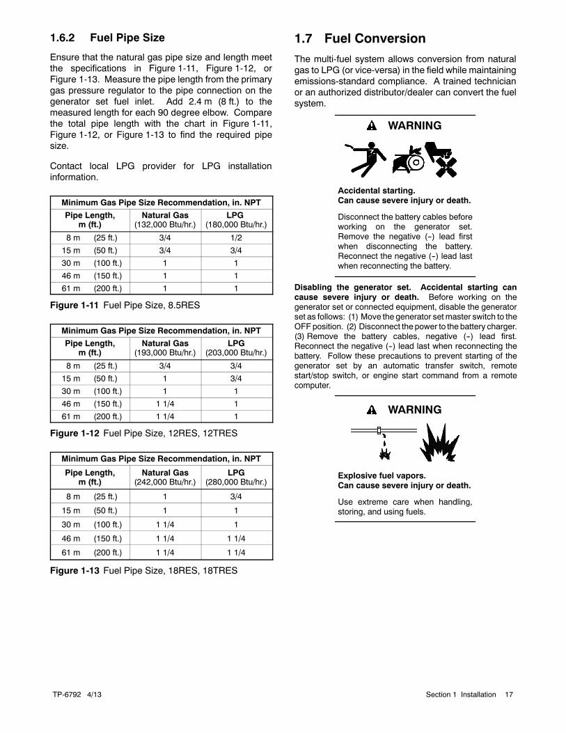
1.6.2 Fuel Pipe Size
Ensure that the natural gas pipe size and length meetthe specifications in Figure 1-11, Figure 1-12, orFigure 1-13. Measure the pipe length from the primarygas pressure regulator to the pipe connection on thegenerator set fuel inlet. Add 2.4 m (8 ft.) to themeasured length for each 90 degree elbow. Comparethe total pipe length with the chart in Figure 1-11,Figure 1-12, or Figure 1-13 to find the required pipesize.
Contact local LPG provider for LPG installationinformation.
Minimum Gas Pipe Size Recommendation, in. NPT
Pipe Length,m (ft.)
Natural Gas(132,000 Btu/hr.)
LPG(180,000 Btu/hr.)
8 m (25 ft.) 3/4 1/2
15 m (50 ft.) 3/4 3/4
30 m (100 ft.) 1 1
46 m (150 ft.) 1 1
61 m (200 ft.) 1 1
Figure 1-11 Fuel Pipe Size, 8.5RES
Minimum Gas Pipe Size Recommendation, in. NPT
Pipe Length,m (ft.)
Natural Gas(193,000 Btu/hr.)
LPG(203,000 Btu/hr.)
8 m (25 ft.) 3/4 3/4
15 m (50 ft.) 1 3/4
30 m (100 ft.) 1 1
46 m (150 ft.) 1 1/4 1
61 m (200 ft.) 1 1/4 1
Figure 1-12 Fuel Pipe Size, 12RES, 12TRES
Minimum Gas Pipe Size Recommendation, in. NPT
Pipe Length,m (ft.)
Natural Gas(242,000 Btu/hr.)
LPG(280,000 Btu/hr.)
8 m (25 ft.) 1 3/4
15 m (50 ft.) 1 1
30 m (100 ft.) 1 1/4 1
46 m (150 ft.) 1 1/4 1 1/4
61 m (200 ft.) 1 1/4 1 1/4
Figure 1-13 Fuel Pipe Size, 18RES, 18TRES
1.7 Fuel Conversion
The multi-fuel system allows conversion from naturalgas to LPG (or vice-versa) in the field while maintainingemissions-standard compliance. A trained technicianor an authorized distributor/dealer can convert the fuelsystem.
Accidental starting.Can cause severe injury or death.
Disconnect the battery cables beforeworking on the generator set.Remove the negative (--) lead firstwhen disconnecting the battery.Reconnect the negative (--) lead lastwhen reconnecting the battery.
WARNING
Disabling the generator set. Accidental starting cancause severe injury or death. Before working on thegenerator set or connected equipment, disable the generatorset as follows: (1) Move the generator setmaster switch to theOFFposition. (2) Disconnect the power to the battery charger.(3) Remove the battery cables, negative (--) lead first.Reconnect the negative (--) lead last when reconnecting thebattery. Follow these precautions to prevent starting of thegenerator set by an automatic transfer switch, remotestart/stop switch, or engine start command from a remotecomputer.
Explosive fuel vapors.Can cause severe injury or death.
Use extreme care when handling,storing, and using fuels.
WARNING
TP-6792 4/1318 Section 1 Installation
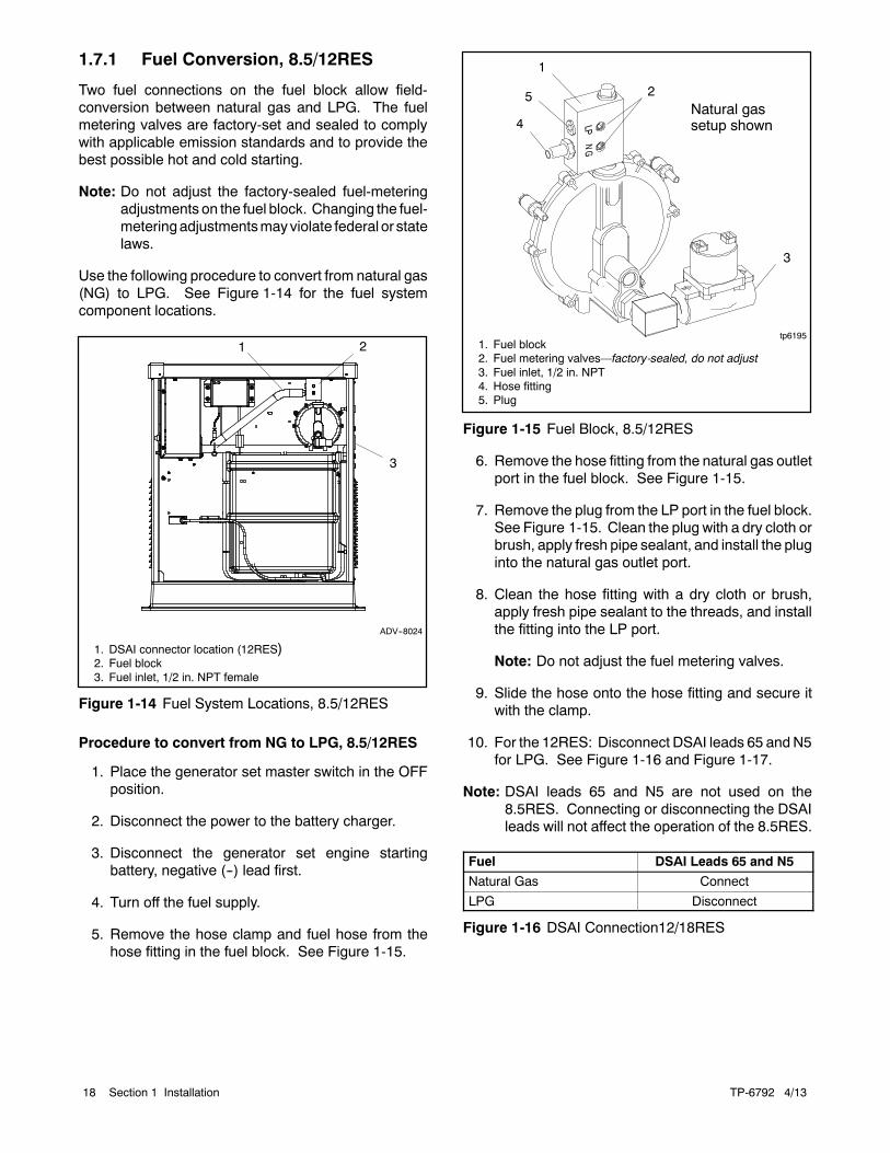
1.7.1 Fuel Conversion, 8.5/12RES
Two fuel connections on the fuel block allow field-conversion between natural gas and LPG. The fuelmetering valves are factory-set and sealed to complywith applicable emission standards and to provide thebest possible hot and cold starting.
Note: Do not adjust the factory-sealed fuel-meteringadjustments on the fuel block. Changing the fuel-meteringadjustmentsmayviolate federal or statelaws.
Use the following procedure to convert from natural gas(NG) to LPG. See Figure 1-14 for the fuel systemcomponent locations.
2
ADV--8024
1. DSAI connector location (12RES)2. Fuel block3. Fuel inlet, 1/2 in. NPT female
3
1
Figure 1-14 Fuel System Locations, 8.5/12RES
Procedure to convert from NG to LPG, 8.5/12RES
1. Place the generator set master switch in the OFFposition.
2. Disconnect the power to the battery charger.
3. Disconnect the generator set engine startingbattery, negative (--) lead first.
4. Turn off the fuel supply.
5. Remove the hose clamp and fuel hose from thehose fitting in the fuel block. See Figure 1-15.
5
tp61951. Fuel block2. Fuel metering valves—factory-sealed, do not adjust3. Fuel inlet, 1/2 in. NPT4. Hose fitting5. Plug
1
2
3
4Natural gassetup shown
Figure 1-15 Fuel Block, 8.5/12RES
6. Remove the hose fitting from the natural gas outletport in the fuel block. See Figure 1-15.
7. Remove the plug from the LP port in the fuel block.See Figure 1-15. Clean the plug with a dry cloth orbrush, apply fresh pipe sealant, and install the pluginto the natural gas outlet port.
8. Clean the hose fitting with a dry cloth or brush,apply fresh pipe sealant to the threads, and installthe fitting into the LP port.
Note: Do not adjust the fuel metering valves.
9. Slide the hose onto the hose fitting and secure itwith the clamp.
10. For the 12RES: Disconnect DSAI leads 65 andN5for LPG. See Figure 1-16 and Figure 1-17.
Note: DSAI leads 65 and N5 are not used on the8.5RES. Connecting or disconnecting the DSAIleads will not affect the operation of the 8.5RES.
Fuel DSAI Leads 65 and N5
Natural Gas Connect
LPG Disconnect
Figure 1-16 DSAI Connection12/18RES
TP-6792 4/13 19Section 1 Installation
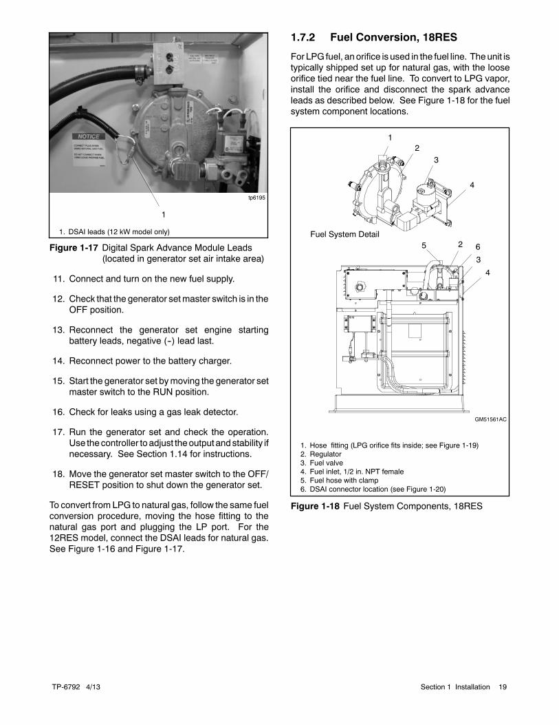
1
tp6195
1. DSAI leads (12 kW model only)
Figure 1-17 Digital Spark Advance Module Leads(located in generator set air intake area)
11. Connect and turn on the new fuel supply.
12. Check that the generator setmaster switch is in theOFF position.
13. Reconnect the generator set engine startingbattery leads, negative (--) lead last.
14. Reconnect power to the battery charger.
15. Start the generator set bymoving the generator setmaster switch to the RUN position.
16. Check for leaks using a gas leak detector.
17. Run the generator set and check the operation.Use thecontroller to adjust theoutputandstability ifnecessary. See Section 1.14 for instructions.
18. Move the generator set master switch to the OFF/RESET position to shut down the generator set.
To convert from LPG to natural gas, follow the same fuelconversion procedure, moving the hose fitting to thenatural gas port and plugging the LP port. For the12RES model, connect the DSAI leads for natural gas.See Figure 1-16 and Figure 1-17.
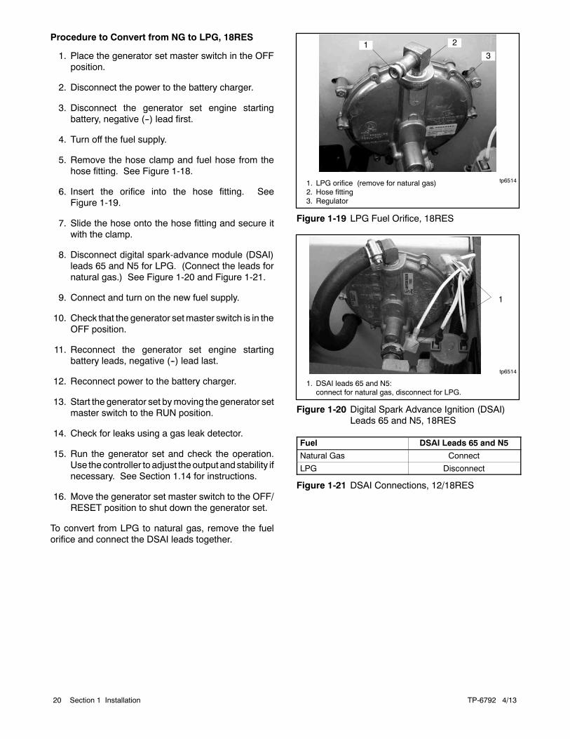
1.7.2 Fuel Conversion, 18RES
For LPG fuel, anorifice is used in the fuel line. Theunit istypically shipped set up for natural gas, with the looseorifice tied near the fuel line. To convert to LPG vapor,install the orifice and disconnect the spark advanceleads as described below. See Figure 1-18 for the fuelsystem component locations.
1. Hose fitting (LPG orifice fits inside; see Figure 1-19)2. Regulator3. Fuel valve4. Fuel inlet, 1/2 in. NPT female5. Fuel hose with clamp6. DSAI connector location (see Figure 1-20)
1
GM51561AC
4
65 2
3
23
Fuel System Detail
4
Figure 1-18 Fuel System Components, 18RES
TP-6792 4/1320 Section 1 Installation
Procedure to Convert from NG to LPG, 18RES
1. Place the generator set master switch in the OFFposition.
2. Disconnect the power to the battery charger.
3. Disconnect the generator set engine startingbattery, negative (--) lead first.
4. Turn off the fuel supply.
5. Remove the hose clamp and fuel hose from thehose fitting. See Figure 1-18.
6. Insert the orifice into the hose fitting. SeeFigure 1-19.
7. Slide the hose onto the hose fitting and secure itwith the clamp.
8. Disconnect digital spark-advance module (DSAI)leads 65 and N5 for LPG. (Connect the leads fornatural gas.) See Figure 1-20 and Figure 1-21.
9. Connect and turn on the new fuel supply.
10. Check that the generator setmaster switch is in theOFF position.
11. Reconnect the generator set engine startingbattery leads, negative (--) lead last.
12. Reconnect power to the battery charger.
13. Start the generator set bymoving the generator setmaster switch to the RUN position.
14. Check for leaks using a gas leak detector.
15. Run the generator set and check the operation.Use thecontroller to adjust theoutputandstability ifnecessary. See Section 1.14 for instructions.
16. Move the generator set master switch to the OFF/RESET position to shut down the generator set.
To convert from LPG to natural gas, remove the fuelorifice and connect the DSAI leads together.
1. LPG orifice (remove for natural gas)2. Hose fitting3. Regulator
1 2
3
tp6514
Figure 1-19 LPG Fuel Orifice, 18RES
tp6514
1. DSAI leads 65 and N5:connect for natural gas, disconnect for LPG.
1
Figure 1-20 Digital Spark Advance Ignition (DSAI)Leads 65 and N5, 18RES
Fuel DSAI Leads 65 and N5
Natural Gas Connect
LPG Disconnect
Figure 1-21 DSAI Connections, 12/18RES
TP-6792 4/13 21Section 1 Installation
1.8 Electrical Connections
Hazardous voltage.Backfeed to the utility system cancause property damage, severeinjury, or death.
If the generator set is used forstandby power, install an automatictransfer switch to prevent inadvertentinterconnection of standby andnormal sources of supply.
WARNING
Grounding electrical equipment. Hazardous voltage cancause severe injury or death. Electrocution is possiblewhenever electricity is present. Ensure you comply with allapplicable codes and standards. Electrically ground thegenerator set, transfer switch, and related equipment andelectrical circuits. Turn off the main circuit breakers of allpower sources before servicing the equipment. Never contactelectrical leads or appliances when standing inwater or onwetground because these conditions increase the risk ofelectrocution.
Electrical backfeed to the utility. Hazardous backfeedvoltage can cause severe injury or death. Install a transferswitch in standby power installations to prevent the connectionof standby and other sources of power. Electrical backfeedinto a utility electrical system can cause severe injury or deathto utility personnel working on power lines.
NOTICECanadian installations only. For standby service connectthe output of the generator set to a suitably rated transferswitch in accordance with Canadian Electrical Code, Part 1.
Have an authorized distributor/dealer or a licensedelectrician make the following electrical connections.The electrical installation must comply with the NationalElectrical Code (NEC) and all applicable local codes.Canadian installations must comply with the CanadianElectrical Code (CEC) and applicable local codes.
Ground the generator set according to applicablecodes. See Section 1.8.3.
1.8.1 Field Connections
The generator set is equipped with a field-connectionterminal block located below the fuel inlet. Leads havebeen factory-installed from the junction box to theterminal block for easy field wiring. Refer to the decalnear the terminal block for connections. Also seeSection 2, Wiring Diagrams.
Refer to the decal below the terminal block and thetransfer switch specifications for the cable size range foreach connection. Route leads through flexible conduit.Use separate conduit for AC wiring and low-voltageengine start leads. Ensure that the leads and conduit donot interfere with the operation of the generator set orobstruct the service areas.
Field Connections to the Terminal Block,Models 8.5/12RES and 18RES
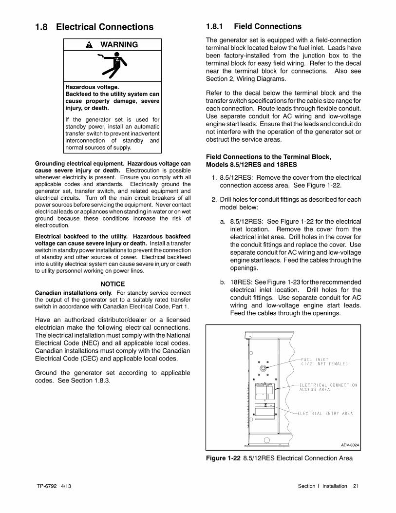
1. 8.5/12RES: Remove the cover from the electricalconnection access area. See Figure 1-22.
2. Drill holes for conduit fittings as described for eachmodel below:
a. 8.5/12RES: See Figure 1-22 for the electricalinlet location. Remove the cover from theelectrical inlet area. Drill holes in the cover forthe conduit fittings and replace the cover. Useseparate conduit for ACwiring and low-voltageengine start leads. Feed the cables through theopenings.
b. 18RES: SeeFigure 1-23 for the recommendedelectrical inlet location. Drill holes for theconduit fittings. Use separate conduit for ACwiring and low-voltage engine start leads.Feed the cables through the openings.
ADV-8024
Figure 1-22 8.5/12RES Electrical Connection Area
TP-6792 4/1322 Section 1 Installation
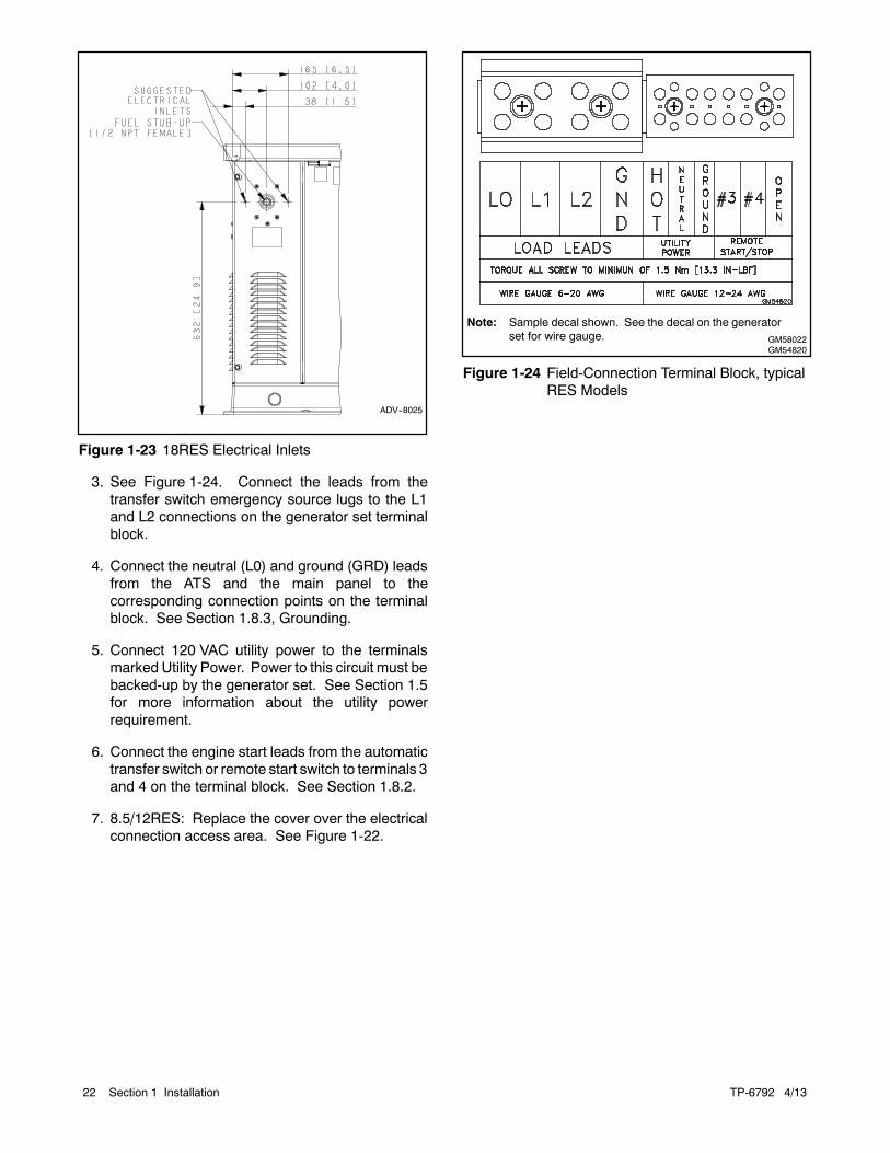
ADV--8025
Figure 1-23 18RES Electrical Inlets
3. See Figure 1-24. Connect the leads from thetransfer switch emergency source lugs to the L1and L2 connections on the generator set terminalblock.
4. Connect the neutral (L0) and ground (GRD) leadsfrom the ATS and the main panel to thecorresponding connection points on the terminalblock. See Section 1.8.3, Grounding.
5. Connect 120 VAC utility power to the terminalsmarked Utility Power. Power to this circuit must bebacked-up by the generator set. See Section 1.5for more information about the utility powerrequirement.
6. Connect the engine start leads from the automatictransfer switch or remote start switch to terminals 3and 4 on the terminal block. See Section 1.8.2.
7. 8.5/12RES: Replace the cover over the electricalconnection access area. See Figure 1-22.
GM58022GM54820
Note: Sample decal shown. See the decal on the generatorset for wire gauge.
Figure 1-24 Field-Connection Terminal Block, typicalRES Models
TP-6792 4/13 23Section 1 Installation
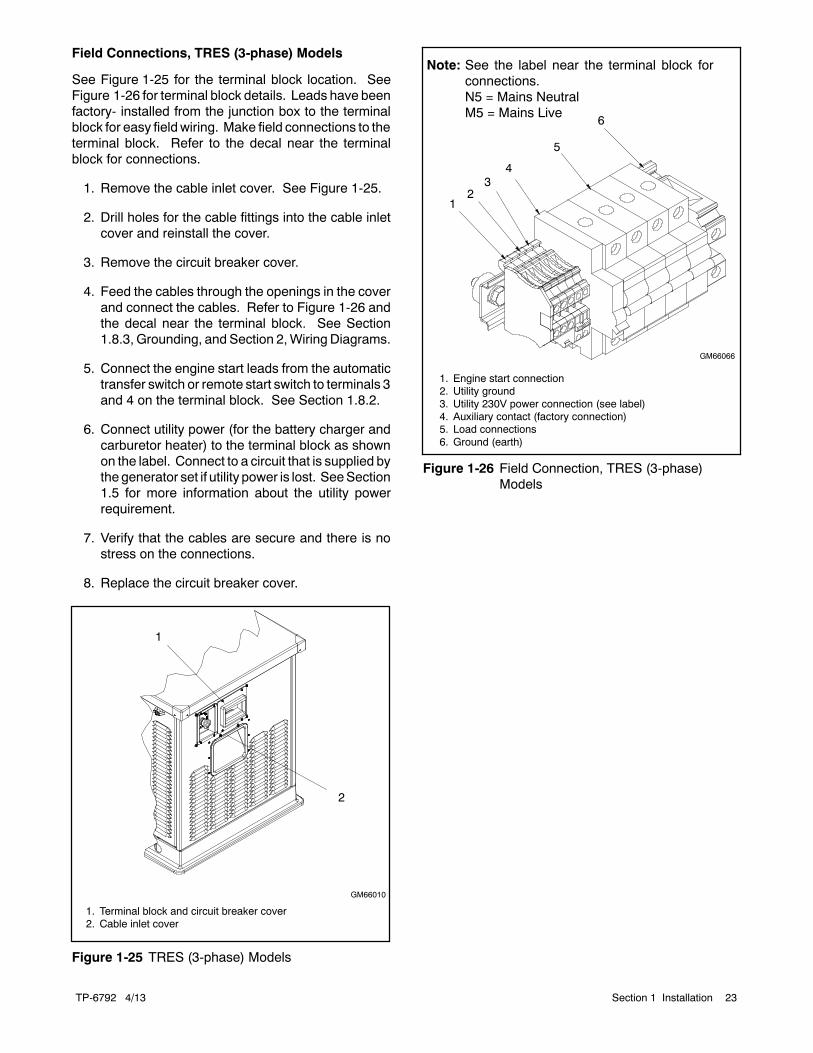
Field Connections, TRES (3-phase) Models
See Figure 1-25 for the terminal block location. SeeFigure 1-26 for terminal block details. Leads have beenfactory- installed from the junction box to the terminalblock for easy fieldwiring. Make field connections to theterminal block. Refer to the decal near the terminalblock for connections.
1. Remove the cable inlet cover. See Figure 1-25.
2. Drill holes for the cable fittings into the cable inletcover and reinstall the cover.
3. Remove the circuit breaker cover.
4. Feed the cables through the openings in the coverand connect the cables. Refer to Figure 1-26 andthe decal near the terminal block. See Section1.8.3, Grounding, and Section 2,Wiring Diagrams.
5. Connect the engine start leads from the automatictransfer switch or remote start switch to terminals 3and 4 on the terminal block. See Section 1.8.2.
6. Connect utility power (for the battery charger andcarburetor heater) to the terminal block as shownon the label. Connect to a circuit that is supplied bythe generator set if utility power is lost. SeeSection1.5 for more information about the utility powerrequirement.
7. Verify that the cables are secure and there is nostress on the connections.
8. Replace the circuit breaker cover.
1
GM66010
1. Terminal block and circuit breaker cover2. Cable inlet cover
2
Figure 1-25 TRES (3-phase) Models
1. Engine start connection2. Utility ground3. Utility 230V power connection (see label)4. Auxiliary contact (factory connection)5. Load connections6. Ground (earth)
6
GM66066
3
5
4
21
Note: See the label near the terminal block forconnections.N5 = Mains NeutralM5 = Mains Live
Figure 1-26 Field Connection, TRES (3-phase)Models
TP-6792 4/1324 Section 1 Installation
1.8.2 Remote Start Connection
Connect terminals 3 and 4 to the automatic transferswitch’s engine start terminals or to an optional remotestart/stop switch. Route the engine start leads throughseparate conduit from the AC power and load leads.
1.8.3 Grounding
Ground the generator set. The grounding methodmustcomply with NEC and local codes. Connect thegrounding strap to the generator set ground lug,terminal GND inside the controller compartment.
Generator sets are shipped with the generator neutralbonded (connected) to the generator ground in thejunction box. The requirement for having a bonded(grounded) or ungrounded neutral is determined by thetype of installation. At installation, the neutral can begrounded at the generator set or lifted from the groundstud and isolated if the installation requires anungrounded neutral connection at the generator. Thegenerator setwill operateproperlywith theneutral eitherbonded to ground or isolated from ground at thegenerator.
Various regulationsandsite configurations including theNational Electrical Code (NEC), local codes, and thetype of transfer switch used in the application determinethe grounding of the neutral at the generator. NECSection 250 is one example that has a very goodexplanation of the neutral grounding requirements forgenerators.
1.8.4 Battery Charger
A battery charger is factory-installed in the batterycompartment to keep the starting battery fully charged.The battery charger’s DC leads are factory-connectedto the battery. Supply power to the generator set for thebattery charger and carburetor heater as described inSections 1.5 and 1.8.1.
RESmodels: Plug the battery charger’s power cord intothe receptacle on the bottom of the controller junctionbox.
TRES (3-phase) models: The battery charger’s powercord is factory-connected.
Refer to the generator set operation manual for batterycharger operation information.
TP-6792 4/13 25Section 1 Installation
1.9 Battery
Sulfuric acid in batteries.Can cause severe injury or death.
Wear protective goggles andclothing. Battery acid may causeblindness and burn skin.
WARNING
Explosion.Can cause severe injury or death.Relays in the battery chargercause arcs or sparks.
Locate the battery in a well-ventilatedarea. Isolate the battery charger fromexplosive fumes.
WARNING
Battery electrolyte is a diluted sulfuric acid. Battery acidcan cause severe injury or death. Battery acid can causeblindness and burn skin. Always wear splashproof safetygoggles, rubber gloves, and boots when servicing the battery.Do not open a sealed battery or mutilate the battery case. Ifbattery acid splashes in the eyes or on the skin, immediatelyflush the affected area for 15 minutes with large quantities ofclean water. Seek immediate medical aid in the case of eyecontact. Never add acid to a battery after placing the battery inservice, as this may result in hazardous spattering of batteryacid.
Battery acid cleanup. Battery acid can cause severeinjury or death. Battery acid is electrically conductive andcorrosive. Add 500 g (1 lb.) of bicarbonate of soda (bakingsoda) to a container with 4 L (1 gal.) of water and mix theneutralizing solution. Pour the neutralizing solution on thespilled battery acid and continue to add the neutralizingsolution to the spilled battery acid until all evidence of achemical reaction (foaming) has ceased. Flush the resultingliquid with water and dry the area.
Battery gases. Explosion can cause severe injury ordeath. Battery gases can cause an explosion. Do not smokeor permit flames or sparks to occur near a battery at any time,particularly when it is charging. Do not dispose of a battery in afire. To prevent burns and sparks that could cause anexplosion, avoid touching the battery terminals with tools orother metal objects. Remove all jewelry before servicing theequipment. Discharge static electricity from your body beforetouching batteries by first touching a grounded metal surfaceaway from the battery. To avoid sparks, do not disturb thebattery charger connections while the battery is charging.Always turn the battery charger off before disconnecting thebattery connections. Ventilate the compartments containingbatteries to prevent accumulation of explosive gases.
Battery short circuits. Explosion can cause severe injuryor death. Short circuits can cause bodily injury and/orequipment damage. Disconnect the battery before generatorset installation or maintenance. Remove all jewelry beforeservicing the equipment. Use tools with insulated handles.Remove the negative (--) lead first when disconnecting thebattery. Reconnect the negative (--) lead last whenreconnecting the battery. Never connect the negative (--)battery cable to the positive (+) connection terminal of thestarter solenoid. Do not test the battery condition by shortingthe terminals together.
Connecting the battery and the battery charger.Hazardous voltage can cause severe injury or death.Reconnect the battery correctly, positive to positive andnegative to negative, to avoid electrical shock and damage tothe battery charger and battery(ies). Have a qualifiedelectrician install the battery(ies).
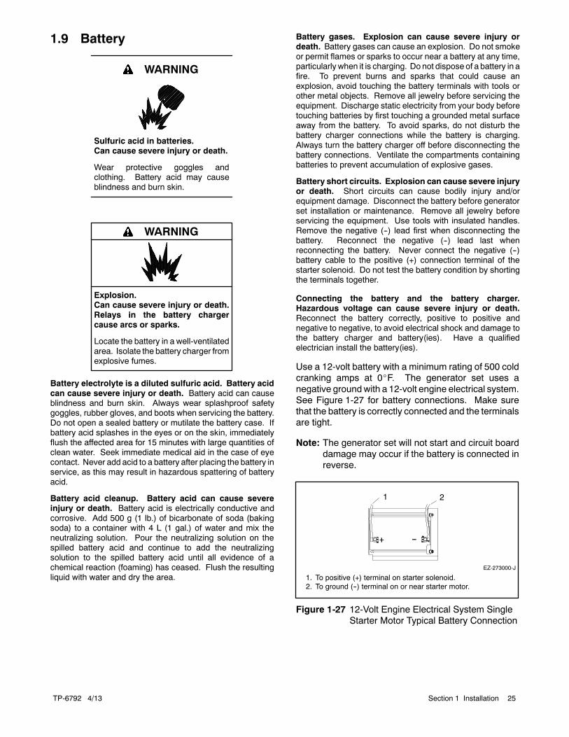
Use a 12-volt battery with a minimum rating of 500 coldcranking amps at 0_F. The generator set uses anegative groundwith a 12-volt engine electrical system.See Figure 1-27 for battery connections. Make surethat the battery is correctly connected and the terminalsare tight.
Note: The generator set will not start and circuit boarddamage may occur if the battery is connected inreverse.
EZ-273000-J
1 2
1. To positive (+) terminal on starter solenoid.2. To ground (--) terminal on or near starter motor.
Figure 1-27 12-Volt Engine Electrical System SingleStarter Motor Typical Battery Connection
TP-6792 4/1326 Section 1 Installation
Figure 1-28 shows the location of the engine startingbattery. Standard battery cables provide easyconnection to the battery. Use the following procedureto install and connect the battery.
ADV-8025
1. Engine starting battery location
1
Figure 1-28 Battery Location, Air Intake End (typical)
Battery Installation Procedure
1. Ensure that the starting battery is fully chargedbefore placing the battery in service.
2. Clean the battery posts and/or adapters ifnecessary.
3. Install the battery post adapters, if needed.
4. Place the battery in the housing.
5. Verify that the controllermaster switch is in theOFFposition.
6. Connect the positive (+) lead to the engine startingbattery.
7. Connect thenegative (--) lead to the engine startingbattery.
Refer to the generator set operation manual and thebattery manufacturer’s instructions for batterymaintenance instructions.
1.10 Accessories
Have accessories installed by an authorized distributor/dealer or a licensed electrician. Follow the installationinstructionsprovidedwitheachkit. Use separate conduitforACandDC leads to reduce thepossibility of electricalinterference. Verify that the leads and conduit do notinterfere with the operation of the generator set orobstruct the service areas. Verify that the electricalinstallation complies with the National Electrical Code(NEC) and all applicable local codes. See Section 2,Wiring Diagrams, for more information regardinggenerator set electrical connections.
If there are no accessories, proceed to Section 1.11,Prestart Installation Check.
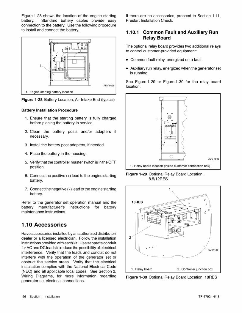
1.10.1 Common Fault and Auxiliary RunRelay Board
The optional relay board provides two additional relaysto control customer-provided equipment:
D Common fault relay, energized on a fault.
D Auxiliary run relay, energized when the generator setis running.
See Figure 1-29 or Figure 1-30 for the relay boardlocation.
1. Relay board location (inside customer connection box)
1
ADV-7948
Figure 1-29 Optional Relay Board Location,8.5/12RES
1. Relay board 2. Controller junction box
1
GM53102
2
18RES
Figure 1-30 Optional Relay Board Location, 18RES
TP-6792 4/13 27Section 1 Installation
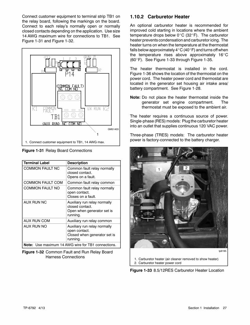
Connect customer equipment to terminal strip TB1 onthe relay board, following the markings on the board.Connect to each relay’s normally open or normallyclosed contacts depending on the application. Use size14 AWG maximum wire for connections to TB1. SeeFigure 1-31 and Figure 1-32.
GM51403
1
1. Connect customer equipment to TB1, 14 AWG max.
Figure 1-31 Relay Board Connections
Terminal Label Description
COMMON FAULT NC Common fault relay normallyclosed contact.Opens on a fault.
COMMON FAULT COM Common fault relay common
COMMON FAULT NO Common fault relay normallyopen contact.Closes on a fault.
AUX RUN NC Auxiliary run relay normallyclosed contact.Open when generator set isrunning.
AUX RUN COM Auxiliary run relay common
AUX RUN NO Auxiliary run relay normallyopen contact.Closed when generator set isrunning.
Note: Use maximum 14 AWG wire for TB1 connections.
Figure 1-32 Common Fault and Run Relay BoardHarness Connections
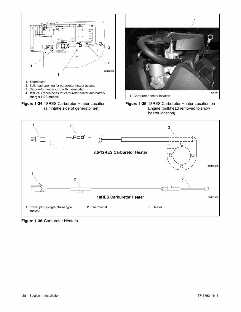
1.10.2 Carburetor Heater
An optional carburetor heater is recommended forimproved cold starting in locations where the ambienttemperature drops below 0_C (32_F). The carburetorheater preventscondensationandcarburetor icing. Theheater turns on when the temperature at the thermostatfalls belowapproximately 4_C(40_F) and turnsoffwhenthe temperature rises above approximately 16_C(60_F). See Figure 1-33 through Figure 1-35.
The heater thermostat is installed in the cord.Figure 1-36 shows the location of the thermostat on thepower cord. The heater power cord and thermostat arelocated in the generator set housing air intake area/battery compartment. See Figure 1-28.
Note: Do not place the heater thermostat inside thegenerator set engine compartment. Thethermostat must be exposed to the ambient air.
The heater requires a continuous source of power.Single-phase (RES)models: Plug the carburetor heaterinto an outlet that supplies continuous 120 VAC power.
Three-phase (TRES) models: The carburetor heaterpower is factory-connected to the battery charger.
tp6195
1. Carburetor heater (air cleaner removed to show heater)2. Carburetor heater power cord
1 2
Figure 1-33 8.5/12RES Carburetor Heater Location
TP-6792 4/1328 Section 1 Installation
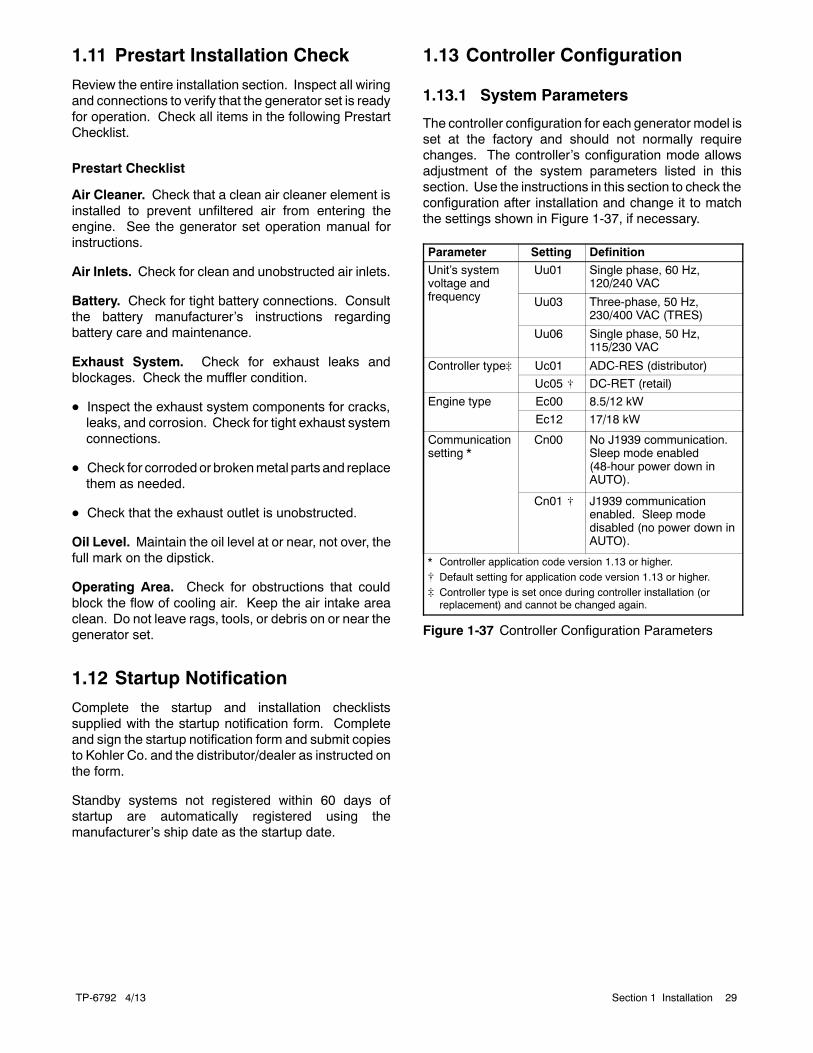
4GM57969
1. Thermostat2. Bulkhead opening for carburetor heater access3. Carburetor heater cord with thermostat4. 120 VAC receptacles for carburetor heater and battery
charger RES models)
3
2
1
Figure 1-34 18RES Carburetor Heater Location(air intake side of generator set)
1
tp6514
1. Carburetor heater location
Figure 1-35 18RES Carburetor Heater Location onEngine (bulkhead removed to showheater location)
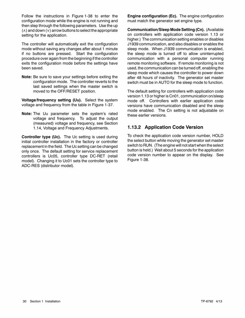
GM19463
2
1. Power plug (single-phase typeshown)
2. Thermostat 3. Heater
3
8.5/12RES Carburetor Heater
2 3
18RES Carburetor Heater GM57968
1
1
Figure 1-36 Carburetor Heaters
TP-6792 4/13 29Section 1 Installation
1.11 Prestart Installation Check
Review the entire installation section. Inspect all wiringand connections to verify that the generator set is readyfor operation. Check all items in the following PrestartChecklist.
Prestart Checklist
Air Cleaner. Check that a clean air cleaner element isinstalled to prevent unfiltered air from entering theengine. See the generator set operation manual forinstructions.
Air Inlets. Check for clean and unobstructed air inlets.
Battery. Check for tight battery connections. Consultthe battery manufacturer’s instructions regardingbattery care and maintenance.
Exhaust System. Check for exhaust leaks andblockages. Check the muffler condition.
D Inspect the exhaust system components for cracks,leaks, and corrosion. Check for tight exhaust systemconnections.
D Check for corrodedor brokenmetal parts and replacethem as needed.
D Check that the exhaust outlet is unobstructed.
Oil Level. Maintain the oil level at or near, not over, thefull mark on the dipstick.
Operating Area. Check for obstructions that couldblock the flow of cooling air. Keep the air intake areaclean. Do not leave rags, tools, or debris on or near thegenerator set.
1.12 Startup Notification
Complete the startup and installation checklistssupplied with the startup notification form. Completeand sign the startup notification form and submit copiesto Kohler Co. and the distributor/dealer as instructed onthe form.
Standby systems not registered within 60 days ofstartup are automatically registered using themanufacturer’s ship date as the startup date.
1.13 Controller Configuration
1.13.1 System Parameters
The controller configuration for each generator model isset at the factory and should not normally requirechanges. The controller’s configuration mode allowsadjustment of the system parameters listed in thissection. Use the instructions in this section to check theconfiguration after installation and change it to matchthe settings shown in Figure 1-37, if necessary.
Parameter Setting Definition
Unit’s systemvoltage andfrequency
Uu01 Single phase, 60 Hz,120/240 VAC
Uu03 Three-phase, 50 Hz,230/400 VAC (TRES)
Uu06 Single phase, 50 Hz,115/230 VAC
Controller type] Uc01 ADC-RES (distributor)
Uc05 [ DC-RET (retail)
Engine type Ec00 8.5/12 kW
Ec12 17/18 kW
Communicationsetting *
Cn00 No J1939 communication.Sleep mode enabled(48-hour power down inAUTO).
Cn01 [ J1939 communicationenabled. Sleep modedisabled (no power down inAUTO).
* Controller application code version 1.13 or higher.[ Default setting for application code version 1.13 or higher.] Controller type is set once during controller installation (orreplacement) and cannot be changed again.
Figure 1-37 Controller Configuration Parameters
TP-6792 4/1330 Section 1 Installation
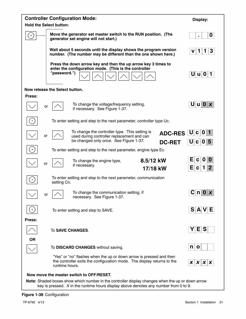
Follow the instructions in Figure 1-38 to enter theconfiguration mode while the engine is not running andthen step through the following parameters. Use the up() anddown () arrowbuttons to select theappropriatesetting for the application.
The controller will automatically exit the configurationmode without saving any changes after about 1 minuteif no buttons are pressed. Start the configurationprocedure over again from the beginning if the controllerexits the configuration mode before the settings havebeen saved.
Note: Be sure to save your settings before exiting theconfiguration mode. The controller reverts to thelast saved settings when the master switch ismoved to the OFF/RESET position.
Voltage/frequency setting (Uu). Select the systemvoltage and frequency from the table in Figure 1-37.
Note: The Uu parameter sets the system’s ratedvoltage and frequency. To adjust the output(measured) voltage and frequency, see Section1.14, Voltage and Frequency Adjustments.
Controller type (Uc). The Uc setting is used duringinitial controller installation in the factory or controllerreplacement in the field. TheUc setting can be changedonly once. The default setting for service replacementcontrollers is Uc05, controller type DC-RET (retailmodel). Changing it to Uc01 sets the controller type toADC-RES (distributor model).
Engine configuration (Ec). The engine configurationmust match the generator set engine type.
Communication/SleepModeSetting (Cn). (Availableon controllers with application code version 1.13 orhigher.) The communication setting enables or disablesJ1939 communication, and also disables or enables thesleep mode. When J1939 communication is enabled,the sleep mode is turned off to allow uninterruptedcommunication with a personal computer runningremote monitoring software. If remote monitoring is notused, the communication canbe turnedoff, enabling thesleep mode which causes the controller to power downafter 48 hours of inactivity. The generator set masterswitch must be in AUTO for the sleep mode to function.
The default setting for controllers with application codeversion 1.13 or higher isCn01, communication on/sleepmode off. Controllers with earlier application codeversions have communication disabled and the sleepmode enabled. The Cn setting is not adjustable onthese earlier versions.
1.13.2 Application Code Version
To check the application code version number, HOLDthe select button while moving the generator set masterswitch toRUN. (Theenginewill not startwhen theselectbutton is held.) Wait about 5 seconds for the applicationcode version number to appear on the display. SeeFigure 1-38.
TP-6792 4/13 31Section 1 Installation
8.5/12 kW
Wait about 5 seconds until the display shows the program versionnumber. (The number may be different than the one shown here.)
Hold the Select button:
or To change the voltage/frequency setting,if necessary. See Figure 1-37.
To enter setting and step to the next parameter, engine type Ec.
To enter setting and step to SAVE.
Move the generator set master switch to the RUN position. (Thegenerator set engine will not start.)
Display:
orTo change the engine type,if necessary.
U u 0 x
U u 0 1
v 1 1 3
. 0
Press:
Now release the Select button.
S A V E
Note: Shaded boxes show which number in the controller display changes when the up or down arrowkey is pressed. X in the runtime hours display above denotes any number from 0 to 9.
Press the down arrow key and then the up arrow key 3 times toenter the configuration mode. (This is the controller“password.”)
Controller Configuration Mode:
To SAVE CHANGES.
To DISCARD CHANGES without saving.
Y E S
Now move the master switch to OFF/RESET.
n o
x x xx
Press:
“Yes” or “no” flashes when the up or down arrow is pressed and thenthe controller exits the configuration mode. The display returns to theruntime hours.
OR
E c 0 0
17/18 kW E c 1 2
To enter setting and step to the next parameter, communicationsetting Cn.
or To change the communication setting, ifnecessary. See Figure 1-37.
C n 0 x
To enter setting and step to the next parameter, controller type Uc.
orTo change the controller type. This setting isused during controller replacement and canbe changed only once. See Figure 1-37. U c 0 5
U c 0 1ADC-RES
DC-RET
Figure 1-38 Configuration
TP-6792 4/1332 Section 1 Installation
1.14 Voltage and FrequencyAdjustments
Hazardous voltage.Can cause severe injury or death.
Operate the generator set only whenall guards and electrical enclosuresare in place.
Moving parts.
WARNING
Short circuits. Hazardous voltage/current can causesevere injury or death. Short circuits can cause bodily injuryand/or equipment damage. Do not contact electricalconnections with tools or jewelry while making adjustments orrepairs. Remove all jewelry before servicing the equipment.
The controller’s adjustment mode allows adjustment ofthe output voltage and frequency, if necessary. Haveadjustments performed by an authorized distributor/dealer or service technician.
Note: A digital multimeter that measures voltage andfrequency is required for these adjustments.
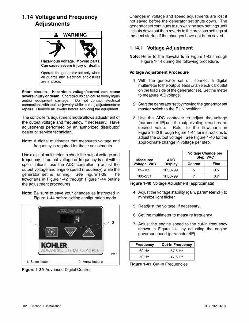
Use a digital multimeter to check the output voltage andfrequency. If output voltage or frequency is not withinspecifications, use the ADC controller to adjust theoutput voltage and engine speed (frequency) while thegenerator set is running. See Figure 1-39. Theflowcharts in Figure 1-42 through Figure 1-44 outlinethe adjustment procedures.
Note: Be sure to save your changes as instructed inFigure 1-44 before exiting configuration mode.
1
tp6514
1. Select button 2. Arrow buttons
2
Figure 1-39 Advanced Digital Control
Changes in voltage and speed adjustments are lost ifnot saved before the generator set shuts down. Thegenerator set continues to runwith the newsettings untilit shuts down but then reverts to the previous settings atthe next startup if the changes have not been saved.
1.14.1 Voltage Adjustment
Note: Refer to the flowcharts in Figure 1-42 throughFigure 1-44 during the following procedure.
Voltage Adjustment Procedure
1. With the generator set off, connect a digitalmultimeter to the output leads or an electrical outleton the load side of the generator set. Set themeterto measure AC voltage.
2. Start the generator set bymoving the generator setmaster switch to the RUN position.
3. Use the ADC controller to adjust the voltage(parameter 1P) until the output voltage reaches thedesired value. Refer to the flowcharts inFigure 1-42 through Figure 1-44 for instructions toadjust the output voltage. See Figure 1-40 for theapproximate change in voltage per step.
MeasuredVoltage, VAC
ADCDisplay
Voltage Change perStep, VAC
Coarse Fine
85--132 1P00--99 5 0.5
180--251 1P00--99 7 0.7
Figure 1-40 Voltage Adjustment (approximate)
4. Adjust the voltage stability (gain, parameter 2P) tominimize light flicker.
5. Readjust the voltage, if necessary.
6. Set the multimeter to measure frequency.
7. Adjust the engine speed to the cut-in frequencyshown in Figure 1-41 by adjusting the enginegovernor speed (parameter 4P).
Frequency Cut-In Frequency
60 Hz 57.5 Hz
50 Hz 47.5 Hz
Figure 1-41 Cut-In Frequencies
TP-6792 4/13 33Section 1 Installation
8. Adjust the volts/Hz (parameter 3P) until the voltagelevel measured by the multimeter begins to drop.When the volts/Hz is set correctly, the generator(as load is applied) attempts to maintain normaloutput until the engine speed drops below thecut-in frequency set in step 7.
9. Reset the engine speed to the operating frequency(50 or 60 Hz) by adjusting the engine governorspeed (parameter 4P).
10. Readjust the voltage stability (gain, parameter 2P),if necessary.
11. Readjust the voltage (parameter 1P), if necessary.
12. Save settings. See Figure 1-44.
13. Stop the generator set.
1.14.2 Frequency Adjustment
The engine speed determines the generator outputfrequency; 60 Hz units operate at 3600 rpm and 50 Hzunits run at 3000 rpm. Adjust the engine governorspeed and gain to set the output frequency and stabilityusing the following procedure.
Note: Refer to the flowcharts in Figure 1-42 throughFigure 1-44 during the following procedure.
Frequency Adjustment Procedure
Note: Refer to the flowcharts in Figure 1-42 throughFigure 1-44 during the following procedure.
1. Attach a frequencymeter to the AC output leads oran electrical outlet on the load side of the generatorset.
2. Start and run the generator set until it reachesnormal operating temperature (at least 10 minutes).
3. Adjust electronic governor speed (parameter 4P)to obtain a frequency reading of 60 Hz (or 50 Hz ifappropriate). Eachstepchanges theenginespeedabout 3.6 rpm, which changes the outputfrequency about 0.06 Hz.
4. Check stability with the generator set running andwith no load applied. If the generator set speed isunstable, hunts, or surges, adjust the governorstability (gain, parameter 5P) until the generatorset becomes stable with no hunting or surging.(Increasing the gain slows the governor response.)
5. Check the frequency reading. Repeat steps 3 and4 if necessary to obtain the rated frequency andstable operation.
6. Save settings. See Figure 1-44.
TP-6792 4/1334 Section 1 Installation
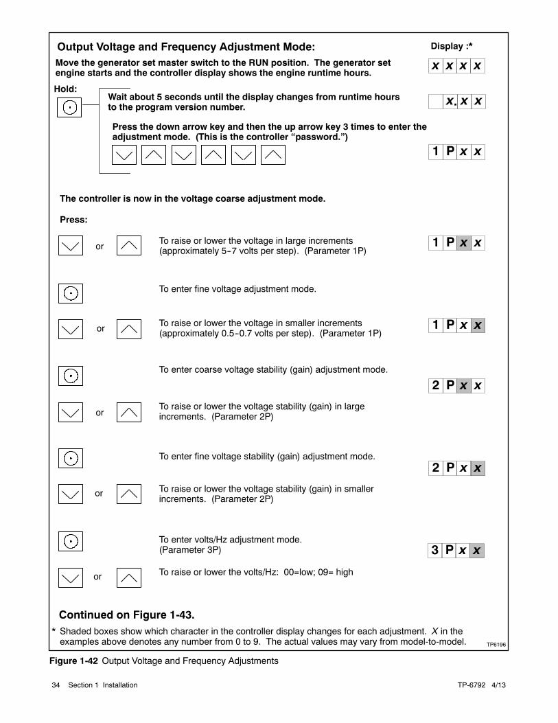
TP6196
Move the generator set master switch to the RUN position. The generator setengine starts and the controller display shows the engine runtime hours.
Display :*
or
or
To raise or lower the voltage in large increments(approximately 5--7 volts per step). (Parameter 1P)
To enter fine voltage adjustment mode.
To raise or lower the voltage in smaller increments(approximately 0.5--0.7 volts per step). (Parameter 1P)
To enter coarse voltage stability (gain) adjustment mode.
or
To raise or lower the voltage stability (gain) in largeincrements. (Parameter 2P)
To enter fine voltage stability (gain) adjustment mode.
or
To raise or lower the voltage stability (gain) in smallerincrements. (Parameter 2P)
To enter volts/Hz adjustment mode.(Parameter 3P)
To raise or lower the volts/Hz: 00=low; 09= high
or
Hold:Wait about 5 seconds until the display changes from runtime hoursto the program version number.
Press the down arrow key and then the up arrow key 3 times to enter theadjustment mode. (This is the controller “password.”)
x x
x x x x
1 P
2 P
* Shaded boxes show which character in the controller display changes for each adjustment. X in theexamples above denotes any number from 0 to 9. The actual values may vary from model-to-model.
x.
2 P
3 P x
The controller is now in the voltage coarse adjustment mode.
Press:
1 P
Continued on Figure 1-43.
x x
x x
x x
xx
x
Output Voltage and Frequency Adjustment Mode:
1 P x x
Figure 1-42 Output Voltage and Frequency Adjustments
TP-6792 4/13 35Section 1 Installation
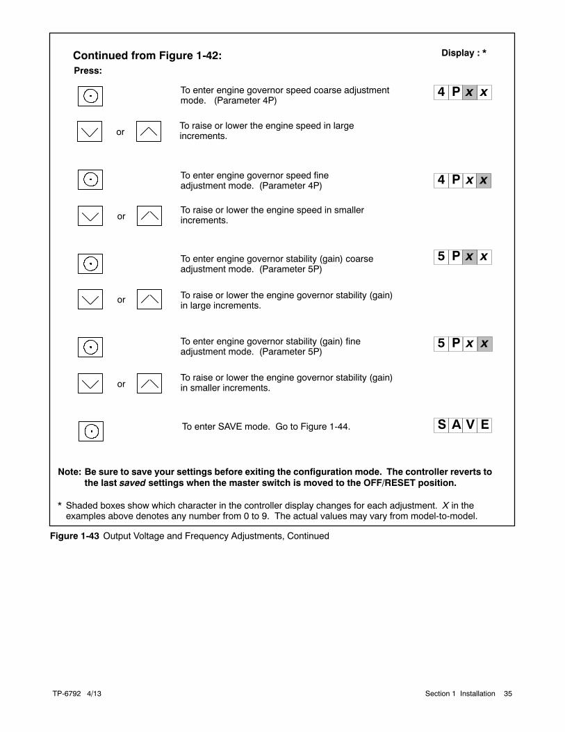
Display : *
or
To enter engine governor speed coarse adjustmentmode. (Parameter 4P)
To raise or lower the engine speed in largeincrements.
To enter engine governor stability (gain) coarseadjustment mode. (Parameter 5P)
To raise or lower the engine governor stability (gain)in large increments.
To enter engine governor speed fineadjustment mode. (Parameter 4P)
To raise or lower the engine speed in smallerincrements.
To enter engine governor stability (gain) fineadjustment mode. (Parameter 5P)
To raise or lower the engine governor stability (gain)in smaller increments.
4 P
4 P
or
or
or
Continued from Figure 1-42:Press:
5 P
5 P
* Shaded boxes show which character in the controller display changes for each adjustment. X in theexamples above denotes any number from 0 to 9. The actual values may vary from model-to-model.
S A V ETo enter SAVE mode. Go to Figure 1-44.
x x
xx
x x
xx
Note: Be sure to save your settings before exiting the configuration mode. The controller reverts tothe last saved settings when the master switch is moved to the OFF/RESET position.
Figure 1-43 Output Voltage and Frequency Adjustments, Continued
TP-6792 4/1336 Section 1 Installation
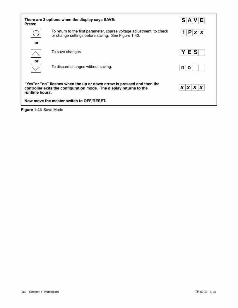
To save changes.
To discard changes without saving.or
S A V E
Y E S
Now move the master switch to OFF/RESET.
n o
There are 3 options when the display says SAVE:Press:
or
To return to the first parameter, coarse voltage adjustment, to checkor change settings before saving. See Figure 1-42.
“Yes”or “no” flashes when the up or down arrow is pressed and then thecontroller exits the configuration mode. The display returns to theruntime hours.
1 P
x x x x
x x
Figure 1-44 Save Mode
TP-6792 4/13 37Section 2 Dimension Drawings and Wiring Diagrams
Section 2 Dimension Drawings and Wiring Diagrams
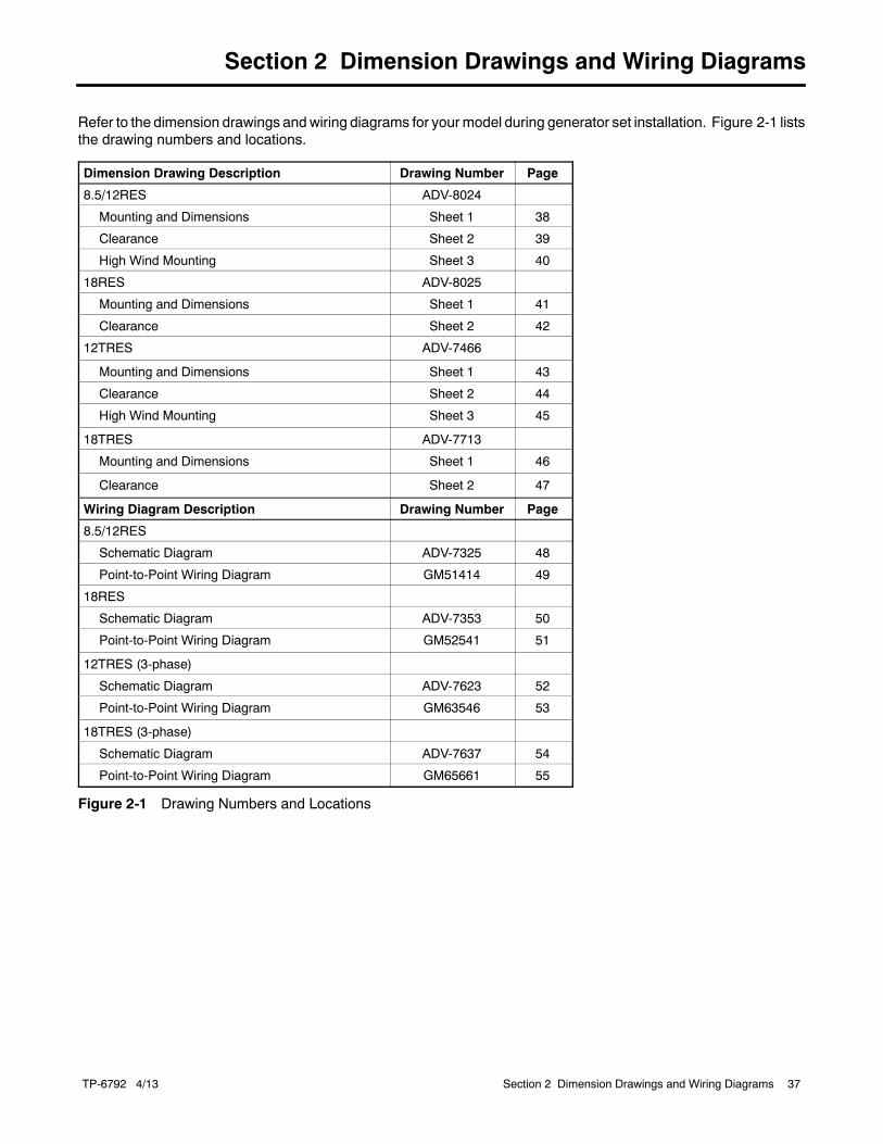
Refer to the dimension drawings andwiring diagrams for yourmodel during generator set installation. Figure 2-1 liststhe drawing numbers and locations.
Dimension Drawing Description Drawing Number Page
8.5/12RES ADV-8024
Mounting and Dimensions Sheet 1 38
Clearance Sheet 2 39
High Wind Mounting Sheet 3 40
18RES ADV-8025
Mounting and Dimensions Sheet 1 41
Clearance Sheet 2 42
12TRES ADV-7466
Mounting and Dimensions Sheet 1 43
Clearance Sheet 2 44
High Wind Mounting Sheet 3 45
18TRES ADV-7713
Mounting and Dimensions Sheet 1 46
Clearance Sheet 2 47
Wiring Diagram Description Drawing Number Page
8.5/12RES
Schematic Diagram ADV-7325 48
Point-to-Point Wiring Diagram GM51414 49
18RES
Schematic Diagram ADV-7353 50
Point-to-Point Wiring Diagram GM52541 51
12TRES (3-phase)
Schematic Diagram ADV-7623 52
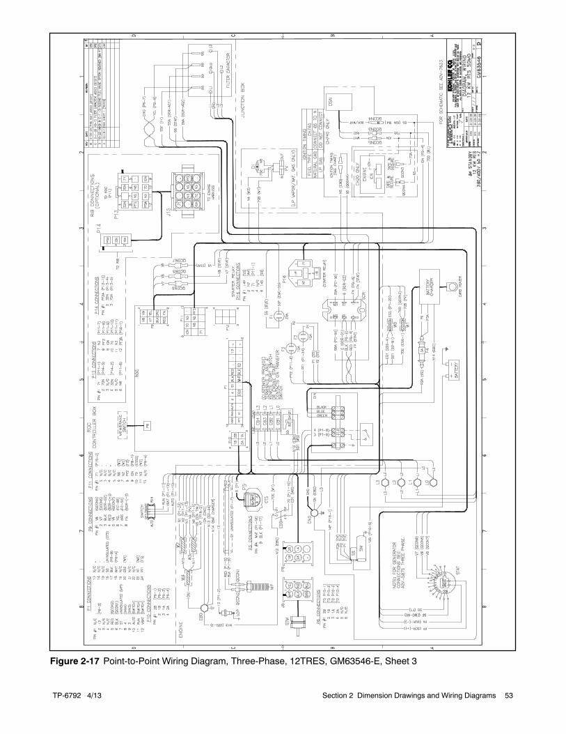
Point-to-Point Wiring Diagram GM63546 53
18TRES (3-phase)
Schematic Diagram ADV-7637 54
Point-to-Point Wiring Diagram GM65661 55
Figure 2-1 Drawing Numbers and Locations
TP-6792 4/1338 Section 2 Dimension Drawings and Wiring Diagrams
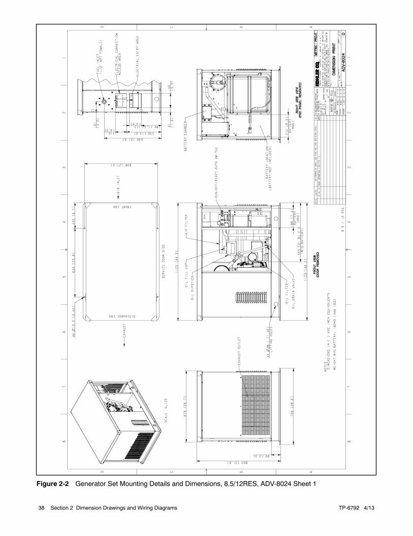
Figure 2-2 Generator Set Mounting Details and Dimensions, 8.5/12RES, ADV-8024 Sheet 1
TP-6792 4/13 39Section 2 Dimension Drawings and Wiring Diagrams
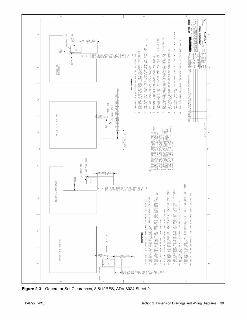
Figure 2-3 Generator Set Clearances, 8.5/12RES, ADV-8024 Sheet 2
TP-6792 4/1340 Section 2 Dimension Drawings and Wiring Diagrams
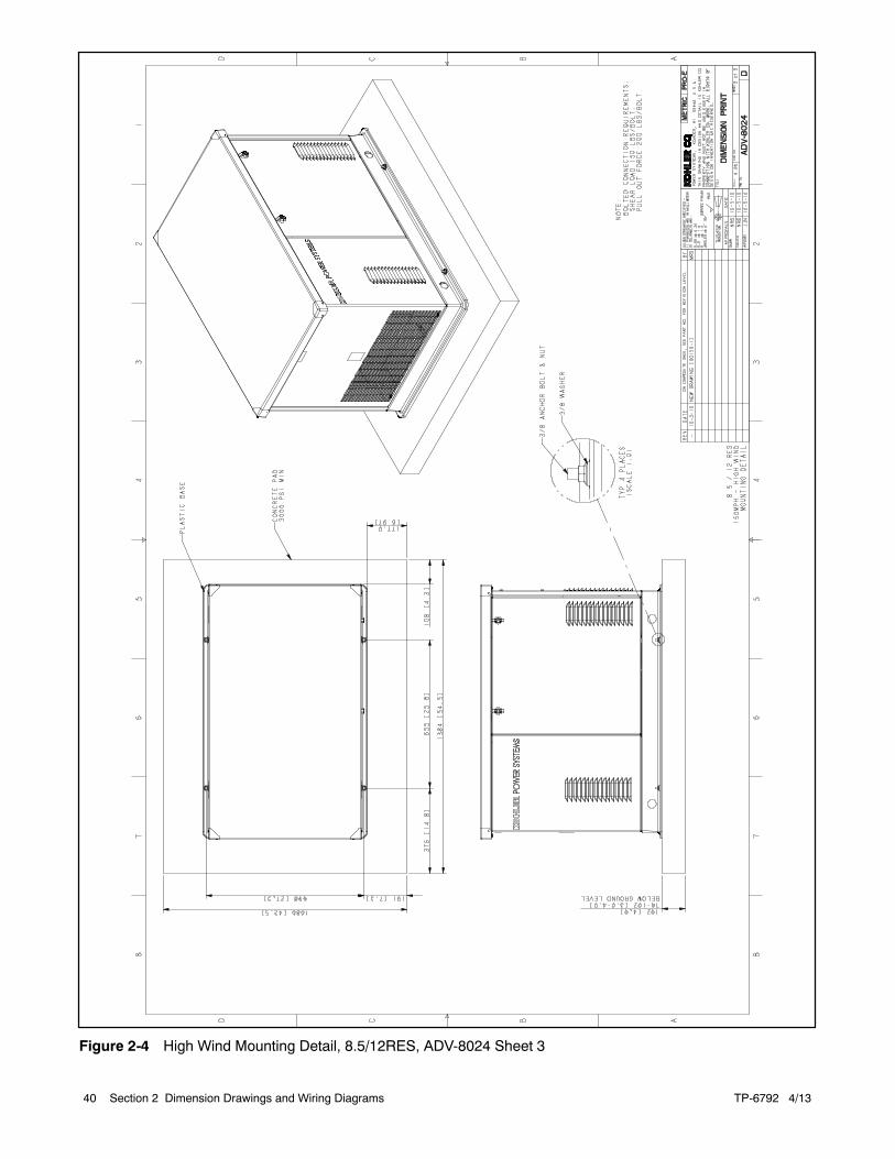
Figure 2-4 High Wind Mounting Detail, 8.5/12RES, ADV-8024 Sheet 3
TP-6792 4/13 41Section 2 Dimension Drawings and Wiring Diagrams
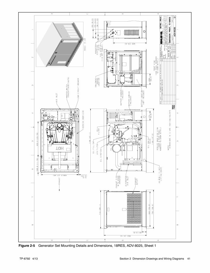
Figure 2-5 Generator Set Mounting Details and Dimensions, 18RES, ADV-8025, Sheet 1
TP-6792 4/1342 Section 2 Dimension Drawings and Wiring Diagrams
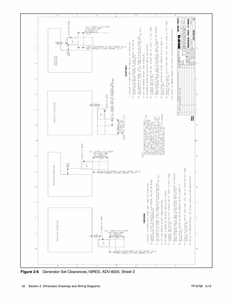
Figure 2-6 Generator Set Clearances,18RES, ADV-8025, Sheet 2
TP-6792 4/13 43Section 2 Dimension Drawings and Wiring Diagrams
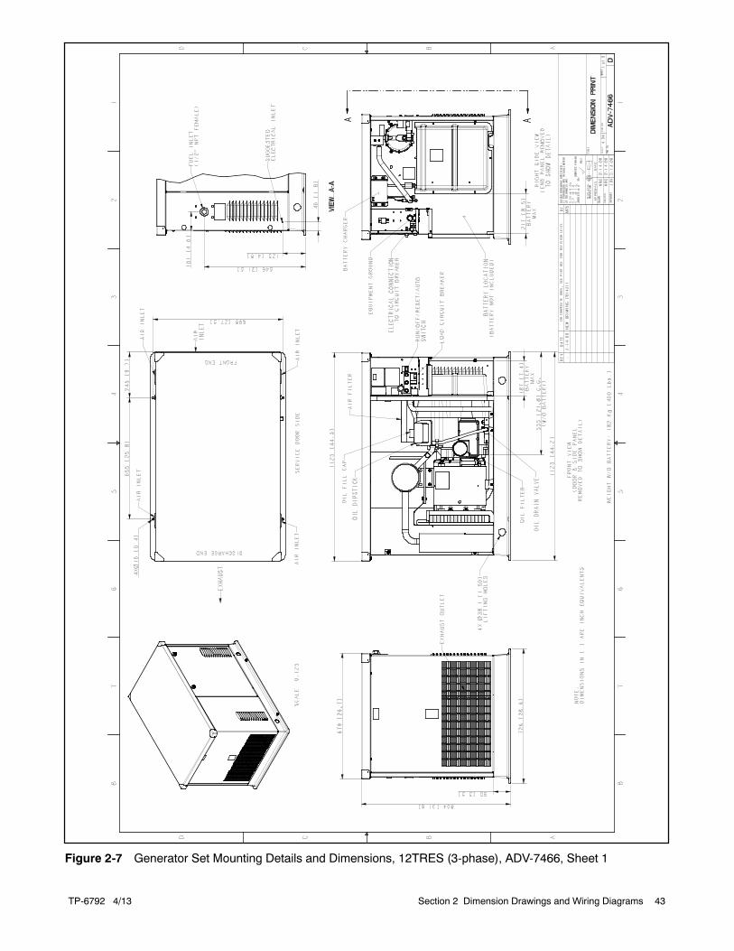
Figure 2-7 Generator Set Mounting Details and Dimensions, 12TRES (3-phase), ADV-7466, Sheet 1
TP-6792 4/1344 Section 2 Dimension Drawings and Wiring Diagrams
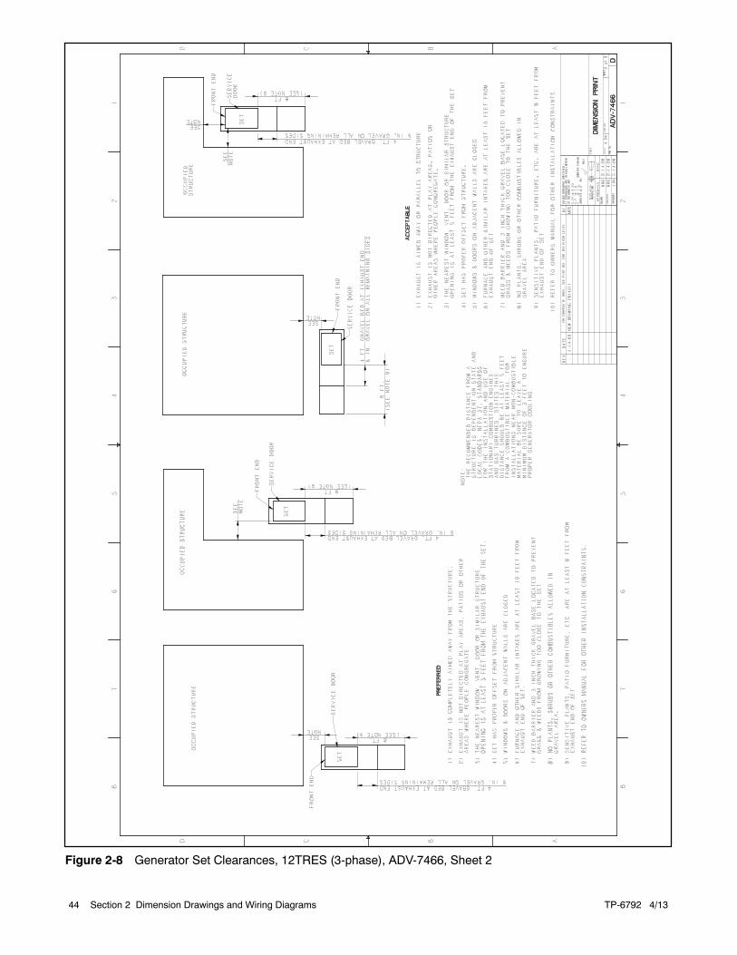
Figure 2-8 Generator Set Clearances, 12TRES (3-phase), ADV-7466, Sheet 2
TP-6792 4/13 45Section 2 Dimension Drawings and Wiring Diagrams
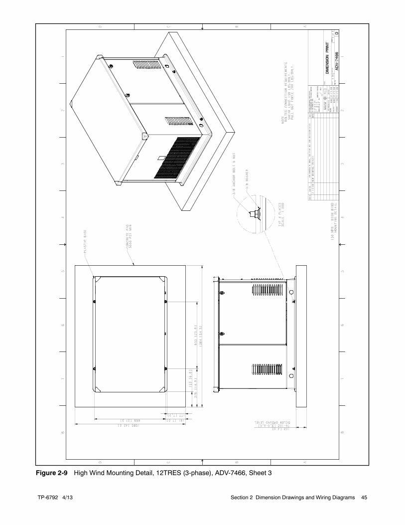
Figure 2-9 High Wind Mounting Detail, 12TRES (3-phase), ADV-7466, Sheet 3
TP-6792 4/1346 Section 2 Dimension Drawings and Wiring Diagrams
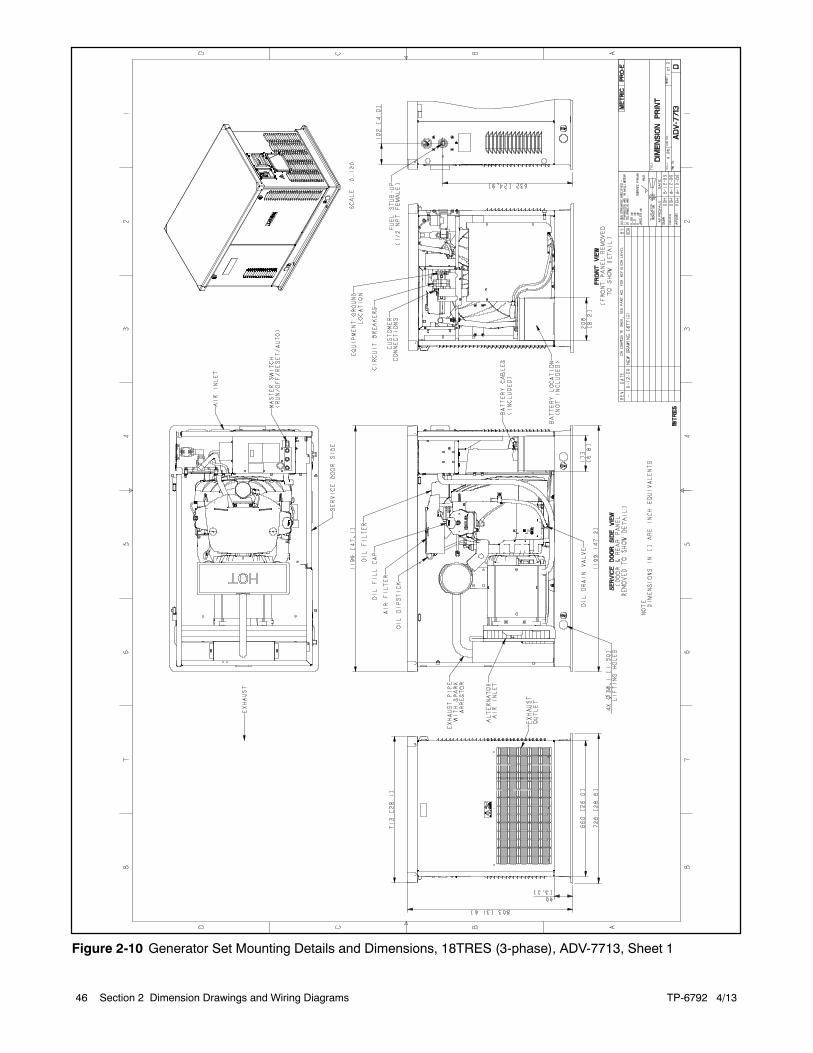
Figure 2-10 Generator Set Mounting Details and Dimensions, 18TRES (3-phase), ADV-7713, Sheet 1
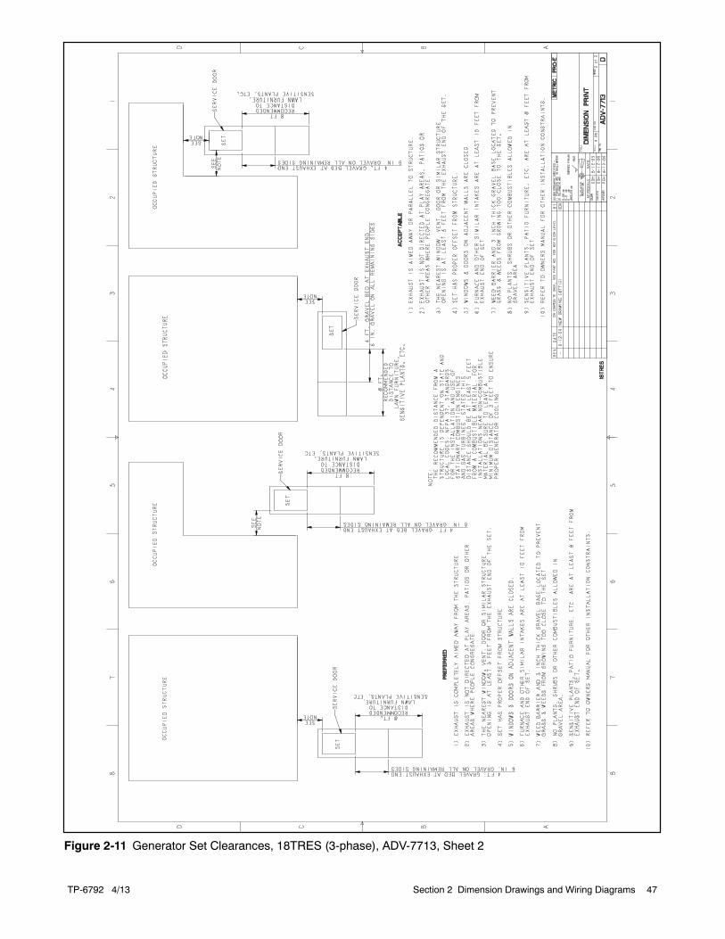
TP-6792 4/13 47Section 2 Dimension Drawings and Wiring Diagrams
Figure 2-11 Generator Set Clearances, 18TRES (3-phase), ADV-7713, Sheet 2
TP-6792 4/1348 Section 2 Dimension Drawings and Wiring Diagrams
-
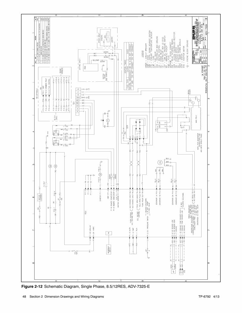
Figure 2-12 Schematic Diagram, Single Phase, 8.5/12RES, ADV-7325-E
TP-6792 4/13 49Section 2 Dimension Drawings and Wiring Diagrams
-
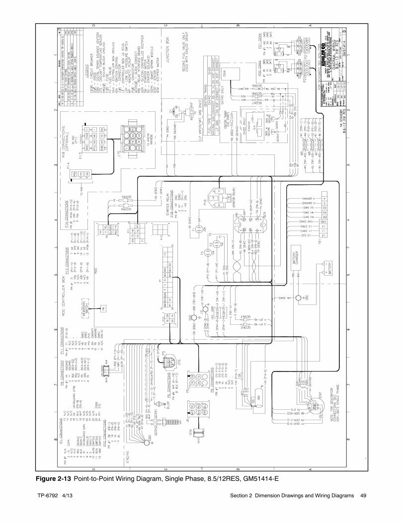
Figure 2-13 Point-to-Point Wiring Diagram, Single Phase, 8.5/12RES, GM51414-E
TP-6792 4/1350 Section 2 Dimension Drawings and Wiring Diagrams
-
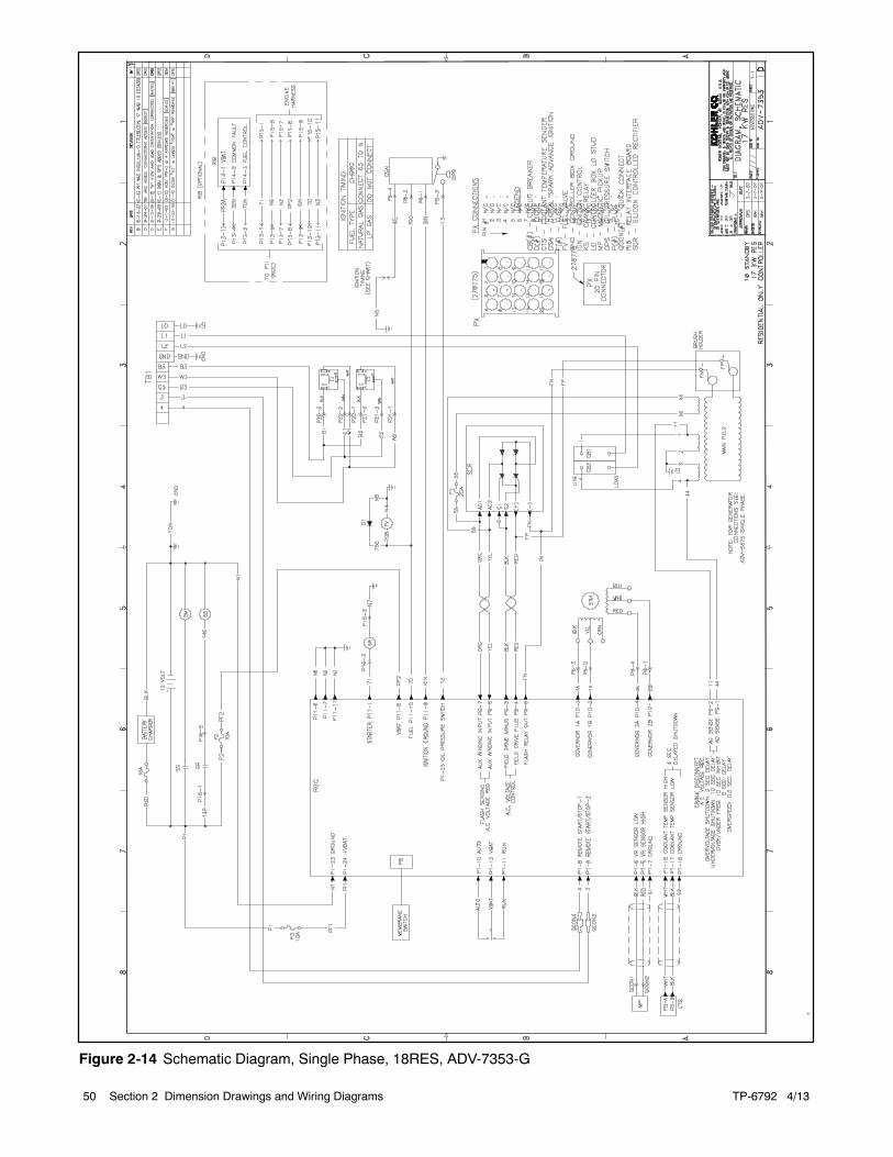
Figure 2-14 Schematic Diagram, Single Phase, 18RES, ADV-7353-G
TP-6792 4/13 51Section 2 Dimension Drawings and Wiring Diagrams
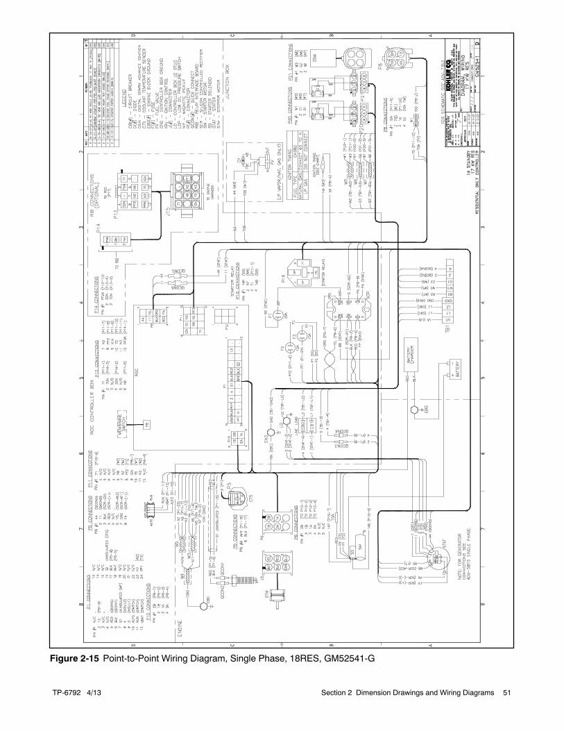
Figure 2-15 Point-to-Point Wiring Diagram, Single Phase, 18RES, GM52541-G
TP-6792 4/1352 Section 2 Dimension Drawings and Wiring Diagrams
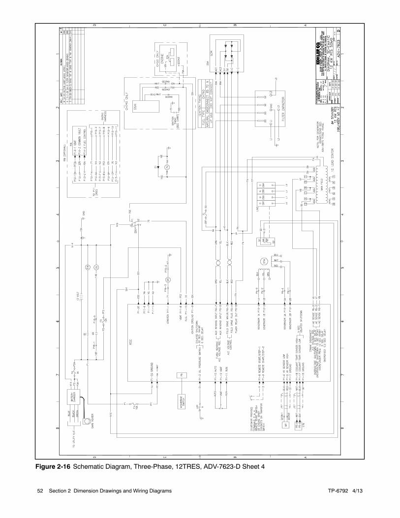
Figure 2-16 Schematic Diagram, Three-Phase, 12TRES, ADV-7623-D Sheet 4
TP-6792 4/13 53Section 2 Dimension Drawings and Wiring Diagrams
Figure 2-17 Point-to-Point Wiring Diagram, Three-Phase, 12TRES, GM63546-E, Sheet 3
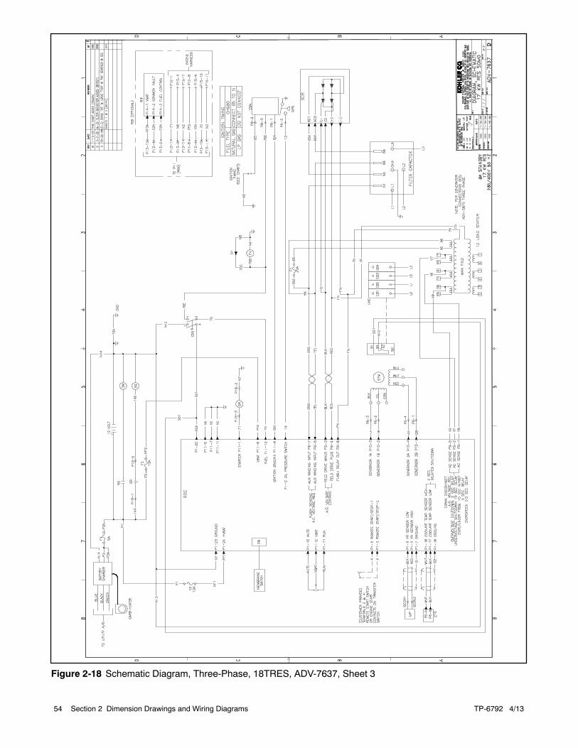
TP-6792 4/1354 Section 2 Dimension Drawings and Wiring Diagrams
Figure 2-18 Schematic Diagram, Three-Phase, 18TRES, ADV-7637, Sheet 3
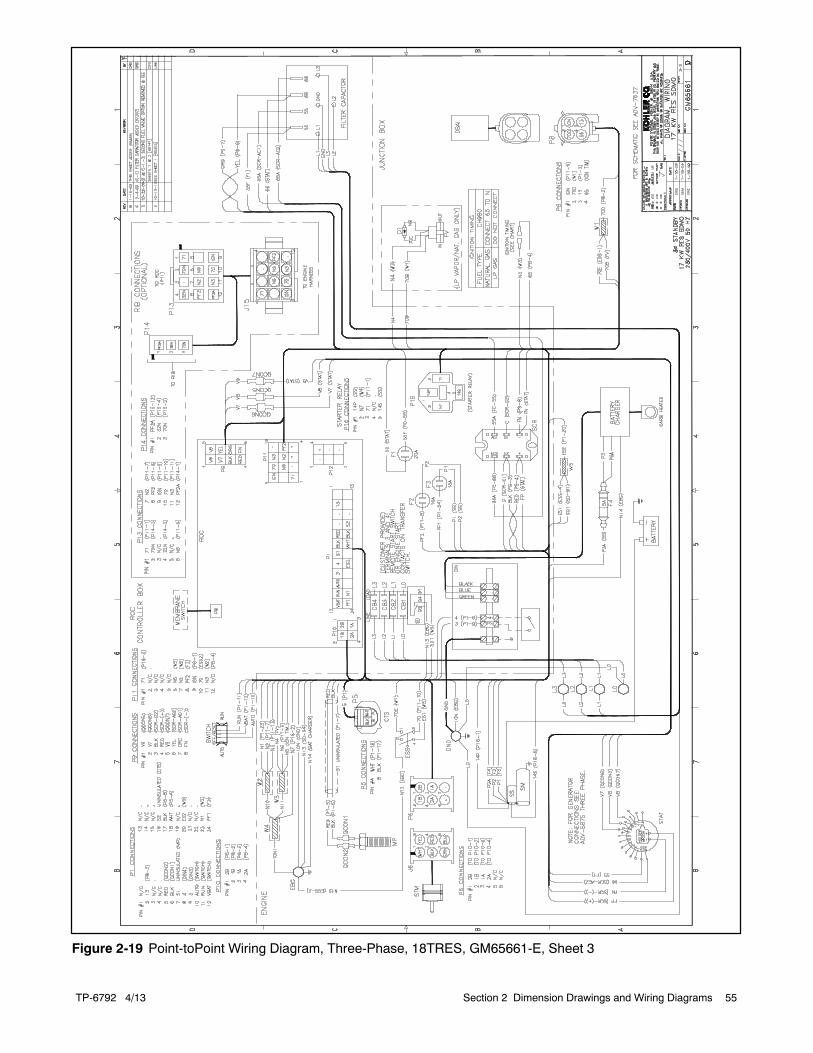
TP-6792 4/13 55Section 2 Dimension Drawings and Wiring Diagrams
Figure 2-19 Point-toPoint Wiring Diagram, Three-Phase, 18TRES, GM65661-E, Sheet 3

TP-6792 4/1356 Section 2 Dimension Drawings and Wiring Diagrams
Notes
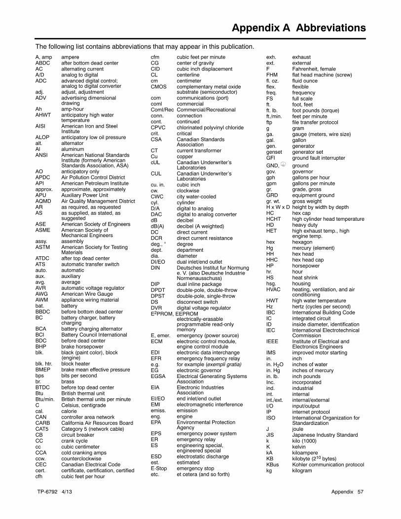
TP-6792 4/13 Appendix 57
Appendix A Abbreviations
The following list contains abbreviations that may appear in this publication.
A, amp ampereABDC after bottom dead centerAC alternating currentA/D analog to digitalADC advanced digital control;
analog to digital converteradj. adjust, adjustmentADV advertising dimensional
drawingAh amp-hourAHWT anticipatory high water
temperatureAISI American Iron and Steel
InstituteALOP anticipatory low oil pressurealt. alternatorAl aluminumANSI American National Standards
Institute (formerly AmericanStandards Association, ASA)
AO anticipatory onlyAPDC Air Pollution Control DistrictAPI American Petroleum Instituteapprox. approximate, approximatelyAPU Auxiliary Power UnitAQMD Air Quality Management DistrictAR as required, as requestedAS as supplied, as stated, as
suggestedASE American Society of EngineersASME American Society of
Mechanical Engineersassy. assemblyASTM American Society for Testing
MaterialsATDC after top dead centerATS automatic transfer switchauto. automaticaux. auxiliaryavg. averageAVR automatic voltage regulatorAWG American Wire GaugeAWM appliance wiring materialbat. batteryBBDC before bottom dead centerBC battery charger, battery
chargingBCA battery charging alternatorBCI Battery Council InternationalBDC before dead centerBHP brake horsepowerblk. black (paint color), block
(engine)blk. htr. block heaterBMEP brake mean effective pressurebps bits per secondbr. brassBTDC before top dead centerBtu British thermal unitBtu/min. British thermal units per minuteC Celsius, centigradecal. calorieCAN controller area networkCARB California Air Resources BoardCAT5 Category 5 (network cable)CB circuit breakerCC crank cyclecc cubic centimeterCCA cold cranking ampsccw. counterclockwiseCEC Canadian Electrical Codecert. certificate, certification, certifiedcfh cubic feet per hour
cfm cubic feet per minuteCG center of gravityCID cubic inch displacementCL centerlinecm centimeterCMOS complementary metal oxide
substrate (semiconductor)com communications (port)coml commercialComl/Rec Commercial/Recreationalconn. connectioncont. continuedCPVC chlorinated polyvinyl chloridecrit. criticalCSA Canadian Standards
AssociationCT current transformerCu coppercUL Canadian Underwriter’s
LaboratoriesCUL Canadian Underwriter’s
Laboratoriescu. in. cubic inchcw. clockwiseCWC city water-cooledcyl. cylinderD/A digital to analogDAC digital to analog converterdB decibeldB(A) decibel (A weighted)DC direct currentDCR direct current resistancedeg., degreedept. departmentdia. diameterDI/EO dual inlet/end outletDIN Deutsches Institut fur Normung
e. V. (also Deutsche IndustrieNormenausschuss)
DIP dual inline packageDPDT double-pole, double-throwDPST double-pole, single-throwDS disconnect switchDVR digital voltage regulatorE2PROM, EEPROM
electrically-erasableprogrammable read-onlymemory
E, emer. emergency (power source)ECM electronic control module,
engine control moduleEDI electronic data interchangeEFR emergency frequency relaye.g. for example (exempli gratia)EG electronic governorEGSA Electrical Generating Systems
AssociationEIA Electronic Industries
AssociationEI/EO end inlet/end outletEMI electromagnetic interferenceemiss. emissioneng. engineEPA Environmental Protection
AgencyEPS emergency power systemER emergency relayES engineering special,
engineered specialESD electrostatic dischargeest. estimatedE-Stop emergency stopetc. et cetera (and so forth)
exh. exhaustext. externalF Fahrenheit, femaleFHM flat head machine (screw)fl. oz. fluid ounceflex. flexiblefreq. frequencyFS full scaleft. foot, feetft. lb. foot pounds (torque)ft./min. feet per minuteftp file transfer protocolg gramga. gauge (meters, wire size)gal. gallongen. generatorgenset generator setGFI ground fault interrupter
GND, groundgov. governorgph gallons per hourgpm gallons per minutegr. grade, grossGRD equipment groundgr. wt. gross weightH x W x D height by width by depthHC hex capHCHT high cylinder head temperatureHD heavy dutyHET high exhaust temp., high
engine temp.hex hexagonHg mercury (element)HH hex headHHC hex head capHP horsepowerhr. hourHS heat shrinkhsg. housingHVAC heating, ventilation, and air
conditioningHWT high water temperatureHz hertz (cycles per second)IBC International Building CodeIC integrated circuitID inside diameter, identificationIEC International Electrotechnical
CommissionIEEE Institute of Electrical and
Electronics EngineersIMS improved motor startingin. inchin. H2O inches of waterin. Hg inches of mercuryin. lb. inch poundsInc. incorporatedind. industrialint. internalint./ext. internal/externalI/O input/outputIP internet protocolISO International Organization for
StandardizationJ jouleJIS Japanese Industry Standardk kilo (1000)K kelvinkA kiloampereKB kilobyte (210 bytes)KBus Kohler communication protocolkg kilogram

TP-6792 4/1358 Appendix
kg/cm2 kilograms per squarecentimeter
kgm kilogram-meterkg/m3 kilograms per cubic meterkHz kilohertzkJ kilojoulekm kilometerkOhm, k kilo-ohmkPa kilopascalkph kilometers per hourkV kilovoltkVA kilovolt amperekVAR kilovolt ampere reactivekW kilowattkWh kilowatt-hourkWm kilowatt mechanicalkWth kilowatt-thermalL literLAN local area networkL x W x H length by width by heightlb. pound, poundslbm/ft3 pounds mass per cubic feetLCB line circuit breakerLCD liquid crystal displayLED light emitting diodeLph liters per hourLpm liters per minuteLOP low oil pressureLP liquefied petroleumLPG liquefied petroleum gasLS left sideLwa sound power level, A weightedLWL low water levelLWT low water temperaturem meter, milli (1/1000)M mega (106 when used with SI
units), malem3 cubic meterm3/hr. cubic meters per hourm3/min. cubic meters per minutemA milliampereman. manualmax. maximumMB megabyte (220 bytes)MCCB molded-case circuit breakerMCM one thousand circular milsmeggar megohmmeterMHz megahertzmi. milemil one one-thousandth of an inchmin. minimum, minutemisc. miscellaneousMJ megajoulemJ millijoulemm millimetermOhm, mmilliohmMOhm, MmegohmMOV metal oxide varistorMPa megapascalmpg miles per gallonmph miles per hourMS military standardms millisecondm/sec. meters per secondmtg. mountingMTU Motoren-und Turbinen-UnionMW megawattmW milliwattF microfaradN, norm. normal (power source)NA not available, not applicablenat. gas natural gas
NBS National Bureau of StandardsNC normally closedNEC National Electrical CodeNEMA National Electrical
Manufacturers AssociationNFPA National Fire Protection
AssociationNm newton meterNO normally openno., nos. number, numbersNPS National Pipe, StraightNPSC National Pipe, Straight-couplingNPT National Standard taper pipe
thread per general useNPTF National Pipe, Taper-FineNR not required, normal relayns nanosecondOC overcrankOD outside diameterOEM original equipment
manufacturerOF overfrequencyopt. option, optionalOS oversize, overspeedOSHA Occupational Safety and Health
AdministrationOV overvoltageoz. ouncep., pp. page, pagesPC personal computerPCB printed circuit boardpF picofaradPF power factorph., phasePHC Phillipsr head Crimptiter
(screw)PHH Phillipsr hex head (screw)PHM pan head machine (screw)PLC programmable logic controlPMG permanent magnet generatorpot potentiometer, potentialppm parts per millionPROM programmable read-only
memorypsi pounds per square inchpsig pounds per square inch gaugept. pintPTC positive temperature coefficientPTO power takeoffPVC polyvinyl chlorideqt. quart, quartsqty. quantityR replacement (emergency)
power sourcerad. radiator, radiusRAM random access memoryRDO relay driver outputref. referencerem. remoteRes/Coml Residential/CommercialRFI radio frequency interferenceRH round headRHM round head machine (screw)rly. relayrms root mean squarernd. roundRO read onlyROM read only memoryrot. rotate, rotatingrpm revolutions per minuteRS right sideRTDs Resistance Temperature
Detectors
RTU remote terminal unitRTV room temperature vulcanizationRW read/writeSAE Society of Automotive
Engineersscfm standard cubic feet per minuteSCR silicon controlled rectifiers, sec. secondSI Systeme international d’unites,
International System of UnitsSI/EO side in/end outsil. silencerSMTP simple mail transfer protocolSN serial numberSNMP simple network management
protocolSPDT single-pole, double-throwSPST single-pole, single-throwspec specificationspecs specification(s)sq. squaresq. cm square centimetersq. in. square inchSMS short message serviceSS stainless steelstd. standardstl. steeltach. tachometerTB terminal blockTCP transmission control protocolTD time delayTDC top dead centerTDEC time delay engine cooldownTDEN time delay emergency to
normalTDES time delay engine startTDNE time delay normal to
emergencyTDOE time delay off to emergencyTDON time delay off to normaltemp. temperatureterm. terminalTHD total harmonic distortionTIF telephone influence factortol. toleranceturbo. turbochargertyp. typical (same in multiple
locations)UF underfrequencyUHF ultrahigh frequencyUIF user interfaceUL Underwriter’s Laboratories, Inc.UNC unified coarse thread (was NC)UNF unified fine thread (was NF)univ. universalURL uniform resource locator
(web address)US undersize, underspeedUV ultraviolet, undervoltageV voltVAC volts alternating currentVAR voltampere reactiveVDC volts direct currentVFD vacuum fluorescent displayVGA video graphics adapterVHF very high frequencyW wattWCR withstand and closing ratingw/ withWO write onlyw/o withoutwt. weightxfmr transformer


E 2011, 2012, 2013, 2015 by Kohler Co. All rights reserved.
TP-6792 4/13c
KOHLER CO. Kohler, Wisconsin 53044Phone 920-457-4441, Fax 920-459-1646
Kohler Power SystemsAsia Pacific Headquarters7 Jurong Pier RoadSingapore 619159Phone (65) 6264-6422, Fax (65) 6264-6455
For the nearest KOHLER authorizedinstallation, service, and sales dealer inthe US and Canada:Call 1-800-544-2444 or visitKOHLERPower.com