Embed Size (px)
Citation preview

Residential/Commercial Generator Sets
Models:
14/20RESA14/20RESAL
Controllers:RDC2DC2
TP-6803 1/15j
Installation

Engine exhaust from this product contains chemicalsknown to the State of California to cause cancer, birthdefects, or other reproductive harm.
WARNINGCalifornia Proposition 65
Product Identification Information
Generator Set Identification NumbersRecord the product identification numbers from thegenerator set nameplate(s).
Model Designation
Specification Number
Serial Number
Accessory Number Accessory Description
Engine IdentificationRecord the product identification information from theengine nameplate.
Manufacturer
Model Designation
Serial Number
Controller IdentificationRecord the controller description from the generator setoperation manual, spec sheet, or sales invoice.
Controller Description

Table of Contents
TP-6803 1/15 Table of Contents 3
Product Identification Information 2. . . . . . . . . . . . . . . . . . . . . . . . . . . . . . . . . . . . . . . . . . . . . . . . . . . . . . . . . . . . .
Safety Precautions and Instructions 5. . . . . . . . . . . . . . . . . . . . . . . . . . . . . . . . . . . . . . . . . . . . . . . . . . . . . . . . .
Introduction 9. . . . . . . . . . . . . . . . . . . . . . . . . . . . . . . . . . . . . . . . . . . . . . . . . . . . . . . . . . . . . . . . . . . . . . . . . . . . . . .Startup and Registration 9. . . . . . . . . . . . . . . . . . . . . . . . . . . . . . . . . . . . . . . . . . . . . . . . . . . . .
Service Assistance 10. . . . . . . . . . . . . . . . . . . . . . . . . . . . . . . . . . . . . . . . . . . . . . . . . . . . . . . . . . . . . . . . . . . . . . . . .
Section 1 Installation 11. . . . . . . . . . . . . . . . . . . . . . . . . . . . . . . . . . . . . . . . . . . . . . . . . . . . . . . . . . . . . . . . . . . . . .1.1 Introduction 11. . . . . . . . . . . . . . . . . . . . . . . . . . . . . . . . . . . . . . . . . . . . . . . . . . . . . . . . . . .1.2 Lifting 11. . . . . . . . . . . . . . . . . . . . . . . . . . . . . . . . . . . . . . . . . . . . . . . . . . . . . . . . . . . . . . . .1.3 Generator Set Inspection 12. . . . . . . . . . . . . . . . . . . . . . . . . . . . . . . . . . . . . . . . . . . . . . .1.4 Location and Mounting 12. . . . . . . . . . . . . . . . . . . . . . . . . . . . . . . . . . . . . . . . . . . . . . . . .
1.4.1 Mounting Area 12. . . . . . . . . . . . . . . . . . . . . . . . . . . . . . . . . . . . . . . . . . . . . . . .1.4.2 Concrete Mounting Pads 12. . . . . . . . . . . . . . . . . . . . . . . . . . . . . . . . . . . . . . .1.4.3 Exhaust Requirements 12. . . . . . . . . . . . . . . . . . . . . . . . . . . . . . . . . . . . . . . . .
1.5 Dimension Drawings 13. . . . . . . . . . . . . . . . . . . . . . . . . . . . . . . . . . . . . . . . . . . . . . . . . . .1.6 Access the Air Intake Area 13. . . . . . . . . . . . . . . . . . . . . . . . . . . . . . . . . . . . . . . . . . . . . .1.7 Fuel Requirements 14. . . . . . . . . . . . . . . . . . . . . . . . . . . . . . . . . . . . . . . . . . . . . . . . . . . . .
1.7.1 Fuel Supply 14. . . . . . . . . . . . . . . . . . . . . . . . . . . . . . . . . . . . . . . . . . . . . . . . . . .1.7.2 Fuel Pipe Size 15. . . . . . . . . . . . . . . . . . . . . . . . . . . . . . . . . . . . . . . . . . . . . . . . .1.7.3 Connecting the Fuel Supply 15. . . . . . . . . . . . . . . . . . . . . . . . . . . . . . . . . . . . .
1.8 Fuel Conversion 16. . . . . . . . . . . . . . . . . . . . . . . . . . . . . . . . . . . . . . . . . . . . . . . . . . . . . . .1.8.1 Fuel Conversion, 14RESA/RESAL Equipped with Fuel Block 16. . . . . . . .1.8.2 Fuel Conversion, 14RESA/RESAL Equipped with Fuel Orifice Fittings 181.8.3 Fuel Conversion, 20RESA/RESAL 20. . . . . . . . . . . . . . . . . . . . . . . . . . . . . . .1.8.4 Regulator Vent Hose 20. . . . . . . . . . . . . . . . . . . . . . . . . . . . . . . . . . . . . . . . . . .
1.9 Electrical Connections 21. . . . . . . . . . . . . . . . . . . . . . . . . . . . . . . . . . . . . . . . . . . . . . . . . .1.9.1 Grounding 22. . . . . . . . . . . . . . . . . . . . . . . . . . . . . . . . . . . . . . . . . . . . . . . . . . . .1.9.2 Electrical Lead Entry 22. . . . . . . . . . . . . . . . . . . . . . . . . . . . . . . . . . . . . . . . . . .1.9.3 Field-Connection Terminal Block 22. . . . . . . . . . . . . . . . . . . . . . . . . . . . . . . . .1.9.4 AC Power Supply 24. . . . . . . . . . . . . . . . . . . . . . . . . . . . . . . . . . . . . . . . . . . . . .
1.10 ATS and Accessory Connections 25. . . . . . . . . . . . . . . . . . . . . . . . . . . . . . . . . . . . . . . .1.10.1 Transfer Switch Connection 25. . . . . . . . . . . . . . . . . . . . . . . . . . . . . . . . . . . . .1.10.2 Communication Cable Specifications 26. . . . . . . . . . . . . . . . . . . . . . . . . . . . .1.10.3 System Connections with Accessory Modules 26. . . . . . . . . . . . . . . . . . . . .
1.11 Battery 30. . . . . . . . . . . . . . . . . . . . . . . . . . . . . . . . . . . . . . . . . . . . . . . . . . . . . . . . . . . . . . .1.12 Generator Set Accessories 32. . . . . . . . . . . . . . . . . . . . . . . . . . . . . . . . . . . . . . . . . . . . . .
1.12.1 Programmable Interface Module (PIM) 32. . . . . . . . . . . . . . . . . . . . . . . . . . .1.12.2 Load Control Module (LCM) 33. . . . . . . . . . . . . . . . . . . . . . . . . . . . . . . . . . . . .1.12.3 Load Shed Kit 34. . . . . . . . . . . . . . . . . . . . . . . . . . . . . . . . . . . . . . . . . . . . . . . . .1.12.4 Regulator Heater 35. . . . . . . . . . . . . . . . . . . . . . . . . . . . . . . . . . . . . . . . . . . . . .1.12.5 Carburetor Heater 37. . . . . . . . . . . . . . . . . . . . . . . . . . . . . . . . . . . . . . . . . . . . .1.12.6 Battery Heater 39. . . . . . . . . . . . . . . . . . . . . . . . . . . . . . . . . . . . . . . . . . . . . . . . .1.12.7 OnCue Plus Generator Management System 40. . . . . . . . . . . . . . . . . . . . . .
1.13 Prestart Installation Check 41. . . . . . . . . . . . . . . . . . . . . . . . . . . . . . . . . . . . . . . . . . . . . .1.14 Set the Exerciser 42. . . . . . . . . . . . . . . . . . . . . . . . . . . . . . . . . . . . . . . . . . . . . . . . . . . . . .
1.14.1 RDC2 Controller 42. . . . . . . . . . . . . . . . . . . . . . . . . . . . . . . . . . . . . . . . . . . . . . .1.14.2 DC2 Controller 42. . . . . . . . . . . . . . . . . . . . . . . . . . . . . . . . . . . . . . . . . . . . . . . .1.14.3 Loaded Exercise 42. . . . . . . . . . . . . . . . . . . . . . . . . . . . . . . . . . . . . . . . . . . . . . .
Section 2 Drawings and Diagrams 43. . . . . . . . . . . . . . . . . . . . . . . . . . . . . . . . . . . . . . . . . . . . . . . . . . . . . . . . . .
Appendix A Abbreviations 55. . . . . . . . . . . . . . . . . . . . . . . . . . . . . . . . . . . . . . . . . . . . . . . . . . . . . . . . . . . . . . . .
Appendix B Electrical Lead Entry Template 57. . . . . . . . . . . . . . . . . . . . . . . . . . . . . . . . . . . . . . . . . . . . . . . . .

TP-6803 1/154
Notes

TP-6803 1/15 5Safety Precautions and Instructions
Safety Precautions and Instructions
IMPORTANTSAFETY INSTRUCTIONS.Electromechanical equipment,including generator sets, transferswitches, switchgear, and accessories,can cause bodily harm and poselife-threatening danger whenimproperly installed, operated, ormaintained. To prevent accidents beaware of potential dangers and actsafely. Read and follow all safetyprecautions and instructions. SAVETHESE INSTRUCTIONS.
Thismanual has several types of safetyprecautions and instructions: Danger,Warning, Caution, and Notice.
DANGER
Danger indicates the presence of ahazard that will cause severepersonal injury, death, orsubstantialproperty damage.
WARNING
Warning indicates the presence of ahazard that can cause severepersonal injury, death, orsubstantialproperty damage.
CAUTION
Caution indicates the presence of ahazard that will or can cause minorpersonal injury or property damage.
NOTICENotice communicates installation,operation, or maintenance informationthat is safety related but not hazardrelated.
Safety decals affixed to the equipmentin prominent places alert the operatoror service technician to potentialhazards and explain how to act safely.The decals are shown throughout thispublication to improve operatorrecognition. Replace missing ordamaged decals.
Accidental Starting
Accidental starting.Can cause severe injury or death.
Disconnect the battery cables beforeworking on the generator set.Remove the negative (--) lead firstwhen disconnecting the battery.Reconnect the negative (--) lead lastwhen reconnecting the battery.
WARNING
Disabling the generator set.Accidental starting can causesevere injury or death. Beforeworking on the generator set orequipment connected to the set,disable the generator set as follows:(1) Press the generator set off/resetbutton to shut down the generator set.(2) Disconnect the power to the batterycharger, if equipped. (3) Remove thebattery cables, negative (--) lead first.Reconnect the negative (--) lead lastwhen reconnecting the battery. Followthese precautions to prevent thestarting of the generator set by theremote start/stop switch.
Battery
Sulfuric acid in batteries.Can cause severe injury or death.
Wear protective goggles andclothing. Battery acid may causeblindness and burn skin.
WARNING
Explosion.Can cause severe injury or death.Relays in the battery chargercause arcs or sparks.
Locate the battery in a well-ventilatedarea. Isolate the battery charger fromexplosive fumes.
WARNING
Battery electrolyte is a dilutedsulfuric acid. Battery acid cancausesevere injury or death. Battery acidcan cause blindness and burn skin.Always wear splashproof safetygoggles, rubber gloves, and bootswhen servicing the battery. Do notopen a sealed battery or mutilate thebattery case. If battery acid splashes inthe eyes or on the skin, immediatelyflush the affected area for 15 minuteswith large quantities of clean water.Seek immediatemedical aid in the caseof eye contact. Never add acid to abattery after placing the battery inservice, as this may result in hazardousspattering of battery acid.
Battery acid cleanup. Battery acidcan cause severe injury or death.Battery acid is electrically conductiveand corrosive. Add 500 g (1 lb.) ofbicarbonate of soda (baking soda) to acontainer with 4 L (1 gal.) of water andmix the neutralizing solution. Pour theneutralizing solution on the spilledbattery acid and continue to add theneutralizing solution to the spilledbattery acid until all evidence of achemical reaction (foaming) hasceased. Flush the resulting liquid withwater and dry the area.

TP-6803 1/156 Safety Precautions and Instructions
Battery gases. Explosion can causesevere injury or death. Battery gasescan cause an explosion. Do not smokeor permit flames or sparks to occur neara battery at any time, particularly whenit is charging. Do not dispose of abattery in a fire. To prevent burns andsparks that could cause an explosion,avoid touching the battery terminalswith tools or other metal objects.Remove all jewelry before servicing theequipment. Discharge static electricityfrom your body before touchingbatteries by first touching a groundedmetal surface away from thebattery. Toavoid sparks, do not disturb the batterycharger connections while the batteryis charging. Always turn the batterycharger off before disconnecting thebattery connections. Ventilate thecompartments containing batteries toprevent accumulation of explosivegases.
Battery short circuits. Explosioncan cause severe injury or death.Short circuits can cause bodily injuryand/or equipment damage.Disconnect the battery beforegenerator set installation ormaintenance. Remove all jewelrybefore servicing the equipment. Usetools with insulated handles. Removethe negative (--) lead first whendisconnecting the battery. Reconnectthe negative (--) lead last whenreconnecting the battery. Neverconnect the negative (--) battery cableto the positive (+) connection terminalof the starter solenoid. Do not test thebattery condition by shorting theterminals together.
Engine Backfire/FlashFire
Fire.Can cause severe injury or death.
Do not smoke or permit flames orsparks near fuels or the fuel system.
WARNING
Servicing the air cleaner. A suddenbackfire can cause severe injury ordeath. Do not operate the generatorset with the air cleaner removed.
Servicing the fuel system. A flashfire cancausesevere injuryor death.Do not smoke or permit flames orsparks near the carburetor, fuel line,fuel filter, fuel pump, or other potentialsources of spilled fuels or fuel vapors.Catch fuels in an approved containerwhen removing the fuel line orcarburetor.
Combustible materials. A fire cancause severe injury or death.Generator set engine fuels and fuelvapors are flammable and explosive.Handle these materials carefully tominimize the risk of fire or explosion.Equip the compartment or nearby areawith a fully charged fire extinguisher.Select a fire extinguisher rated ABC orBC for electrical fires or asrecommended by the local fire code oran authorized agency. Train allpersonnel on fire extinguisheroperation and fire preventionprocedures.
Exhaust System
Carbon monoxide.Can cause severe nausea,fainting, or death.
The exhaust system must beleakproof and routinely inspected.
WARNING
Generator set operation. Carbonmonoxide can cause severe nausea,fainting, or death. Carbon monoxideis an odorless, colorless, tasteless,nonirritating gas that can cause death ifinhaled for even a short time. Avoidbreathing exhaust fumeswhenworkingon or near the generator set. Neveroperate the generator set inside abuilding. Never operate the generatorset where exhaust gas could seepinside or be drawn into a potentiallyoccupied building through windows, airintake vents, or other openings.
Carbon monoxide detectors.Carbon monoxide can cause severenausea, fainting, or death. Installcarbon monoxide detectors on eachlevel of any building adjacent to thegenerator set. Locate the detectors toadequately warn the building’soccupants of the presence of carbonmonoxide. Keep the detectorsoperational at all times. Periodicallytest and replace the carbon monoxidedetectors according to themanufacturer’s instructions.
Carbon monoxide symptoms.Carbon monoxide can cause severenausea, fainting, or death. Carbonmonoxide is a poisonous gas present inexhaust gases. Carbonmonoxide is anodorless, colorless, tasteless,nonirritating gas that can cause death ifinhaled for even a short time. Carbonmonoxide poisoning symptoms includebut are not limited to the following:D Light-headedness, dizzinessD Physical fatigue, weakness injoints and muscles
D Sleepiness, mental fatigue,inability to concentrateor speak clearly, blurred vision
D Stomachache, vomiting, nauseaIf experiencing any of these symptomsand carbon monoxide poisoning ispossible, seek fresh air immediatelyand remain active. Do not sit, lie down,or fall asleep. Alert others to thepossibility of carbon monoxidepoisoning. Seek medical attention ifthe condition of affected persons doesnot improvewithinminutes of breathingfresh air.

TP-6803 1/15 7Safety Precautions and Instructions
Fuel System
Explosive fuel vapors.Can cause severe injury or death.
Use extreme care when handling,storing, and using fuels.
WARNING
The fuel system. Explosive fuelvapors can cause severe injury ordeath. Vaporized fuels are highlyexplosive. Use extreme care whenhandling and storing fuels. Store fuelsin a well-ventilated area away fromspark-producing equipment and out ofthe reach of children. Never add fuel tothe tank while the engine is runningbecause spilled fuel may ignite oncontact with hot parts or from sparks.Do not smoke or permit flames orsparks to occur near sources of spilledfuel or fuel vapors. Keep the fuel linesand connections tight and in goodcondition. Do not replace flexible fuellines with rigid lines. Use flexiblesections to avoid fuel line breakagecausedby vibration. Donot operate thegenerator set in the presence of fuelleaks, fuel accumulation, or sparks.Repair fuel systems before resuminggenerator set operation.
Gas fuel leaks. Explosive fuelvapors can cause severe injury ordeath. Fuel leakage can cause anexplosion. Check the LPG vapor ornatural gas fuel system for leakage byusing a soap and water solution withthe fuel system test pressurized to6--8 ounces per square inch(10--14 inches water column). Do notuse a soap solution containing eitherammonia or chlorine because bothprevent bubble formation. A successfultest depends on the ability of thesolution to bubble.
Explosive fuel vapors can causesevere injury or death. Takeadditional precautions when using thefollowing fuels:
Propane (LPG)—Adequate ventilationis mandatory. Because propane isheavier than air, install propane gasdetectors low in a room. Inspect thedetectors per the manufacturer’sinstructions.
Natural Gas—Adequate ventilation ismandatory. Because natural gas rises,install natural gas detectors high in aroom. Inspect the detectors per themanufacturer’s instructions.
Hazardous Noise
Hazardous noise.Can cause hearing loss.
Never operate the generator setwithout a muffler or with a faultyexhaust system.
CAUTION
Engine noise. Hazardous noise cancause hearing loss. Generator setsnot equipped with sound enclosurescan produce noise levels greater than105 dBA. Prolonged exposure to noiselevels greater than 85 dBA can causepermanent hearing loss. Wear hearingprotection when near an operatinggenerator set.
Hazardous Voltage/Moving Parts
Hazardous voltage.Will cause severe injury or death.
This equipment must be installed andserviced by qualified electricalpersonnel.
DANGER
Hazardous voltage.Can cause severe injury or death.
Operate the generator set only whenall guards and electrical enclosuresare in place.
Moving parts.
WARNING
Hazardous voltage.Backfeed to the utility system cancause property damage, severeinjury, or death.
If the generator set is used forstandby power, install an automatictransfer switch to prevent inadvertentinterconnection of standby andnormal sources of supply.
WARNING
Welding the generator set.Can cause severe electricalequipment damage.
Never weld components of thegenerator set without firstdisconnecting the battery, controllerwiring harness, and engine electroniccontrol module (ECM).
CAUTION
Grounding electrical equipment.Hazardous voltage can causesevere injury or death. Electrocutionis possible whenever electricity ispresent. Ensure you comply with allapplicable codes and standards.Electrically ground the generator set,transfer switch, and related equipmentand electrical circuits. Turn off themaincircuit breakers of all power sourcesbefore servicing the equipment. Nevercontact electrical leads or applianceswhen standing in water or on wetground because these conditionsincrease the risk of electrocution.
Welding on the generator set. Cancause severe electrical equipmentdamage. Before welding on thegenerator set perform the followingsteps: (1) Remove the battery cables,negative (--) lead first. (2) Disconnectall engine electronic control module(ECM) connectors. (3) Disconnect allgenerator set controller and voltageregulator circuit board connectors.(4) Disconnect the engine battery-charging alternator connections.(5) Attach the weld ground connectionclose to the weld location.

TP-6803 1/158 Safety Precautions and Instructions
Connecting the battery and thebattery charger. Hazardous voltagecan cause severe injury or death.Reconnect the battery correctly,positive to positive and negative tonegative, to avoid electrical shock anddamage to the battery charger andbattery(ies). Have a qualifiedelectrician install the battery(ies).
Short circuits. Hazardousvoltage/current can cause severeinjury or death. Short circuits cancause bodily injury and/or equipmentdamage. Do not contact electricalconnections with tools or jewelry whilemaking adjustments or repairs.Remove all jewelry before servicing theequipment.
Electrical backfeed to the utility.Hazardous backfeed voltage cancause severe injury or death. Installa transfer switch in standby powerinstallations to prevent the connectionof standby and other sources of power.Electrical backfeed into a utilityelectrical system can cause severeinjury or death to utility personnelworking on power lines.
Heavy Equipment
Unbalanced weight.Improper lifting can cause severeinjury or death and equipmentdamage.
Do not use lifting eyes.Lift the generator set using lifting barsinserted through the lifting holes onthe skid.
WARNING
Hot Parts
Hot engine and exhaust system.Can cause severe injury or death.
Do not work on the generator set untilit cools.
WARNING
Servicing the exhaust system. Hotparts can cause severe injury ordeath. Do not touch hot engine parts.The engine and exhaust systemcomponents become extremely hotduring operation.
Servicing the engine heater. Hotparts can cause minor personalinjury or property damage. Install theheater before connecting it to power.Operating the heater before installationcan cause burns and componentdamage. Disconnect power to theheater and allow it to cool beforeservicing the heater or nearby parts.
NoticeNOTICE
Canadian installations only. Forstandby service connect the output ofthe generator set to a suitably ratedtransfer switch in accordance withCanadian Electrical Code, Part 1.

TP-6803 1/15 9
Introduction
This manual provides installation instructions forResidential/Commercial Model generator sets. SeeFigure 1. Refer to TP-6804, Operation Manual, forgenerator set operation and maintenance instructions.
The generator set is approved for use in stationaryapplications in locations served by a reliable utilitypower source.
Have a Kohlerr authorized distributor/dealer install thegenerator set outdoors according to the instructions inthismanual. The generator set installationmust complywith the National Electrical Code (NEC) and local coderequirements. Do not install this generator set indoors.
Information in this publication represents data availableat the time of print. Kohler Co. reserves the right tochange this publication and the products representedwithout notice and without any obligation or liabilitywhatsoever.
Read this manual and carefully follow all proceduresand safety precautions to ensure proper equipmentoperation and to avoid bodily injury. Readand follow theSafety Precautions and Instructions section at thebeginning of this manual.
zaa28533
Figure 1 14/20RESA/RESAL Generator Set
List of Related LiteratureFigure 2 identifies related literature available for thegenerator sets covered in thismanual. Only trained andqualified personnel should install or service thegenerator set.
Literature Type Part Number
Operation Manual,14/20RESA/RESALGenerator Set TP-6804
Operation/Installation Manual, ModelRXT Automatic Transfer Switch TP-6807
Service Manual,14/20RESA/RESAL Generator Set TP-6735
Operation Manual, OnCue Plus TP-6928
Operation/Installation Manual,Model RDT Transfer Switch TP-6345
Installation Manual,Model RSB Transfer Switch TP-6486
Operation Manual,Model RSB Transfer Switch TP-6487
Installation Instructions,Load Control Module (LCM) TT-1574
Installation Instructions,Programmable Interface Module (PIM) TT-1584
Installation Instructions,Concrete Mounting Pads TT--1619
Figure 2 Related Literature
Startup and Registration
When the generator set is installed, complete thestartup and installation checklists supplied with thestartup notification form. Complete and sign the startupnotification form and register the unit using the Kohleronline Warranty Processing System.

TP-6803 1/1510
Service Assistance
For professional advice on generator set powerrequirementsandconscientiousservice, pleasecontactyour nearest Kohler distributor or dealer.
D Consult the Yellow Pages under the headingGenerators—Electric.
D Visit the Kohler Power Systems website atKOHLERPower.com.
D Lookat the labels and stickers on yourKohler productor review the appropriate literature or documentsincluded with the product.
D Call toll free in the US and Canada 1-800-544-2444.
D Outside theUSandCanada, call the nearest regionaloffice.
Headquarters Europe, Middle East, Africa(EMEA)Kohler Power Systems Netherlands B.V.Kristallaan 14761 ZC ZevenbergenThe NetherlandsPhone: (31) 168 331630Fax: (31) 168 331631
Asia PacificPower Systems Asia Pacific Regional OfficeSingapore, Republic of SingaporePhone: (65) 6264-6422Fax: (65) 6264-6455
ChinaNorth China Regional Office, BeijingPhone: (86) 10 6518 7950
(86) 10 6518 7951(86) 10 6518 7952
Fax: (86) 10 6518 7955
East China Regional Office, ShanghaiPhone: (86) 21 6288 0500Fax: (86) 21 6288 0550
India, Bangladesh, Sri LankaIndia Regional OfficeBangalore, IndiaPhone: (91) 80 3366208
(91) 80 3366231Fax: (91) 80 3315972
Japan, KoreaNorth Asia Regional OfficeTokyo, JapanPhone: (813) 3440-4515Fax: (813) 3440-2727
Latin AmericaLatin America Regional OfficeLakeland, Florida, USAPhone: (863) 619-7568Fax: (863) 701-7131
TP-6803 1/15 11Section 1 Installation
Section 1 Installation
1.1 Introduction
Hazardous voltage.Will cause severe injury or death.
This equipment must be installed andserviced by qualified electricalpersonnel.
DANGER
Carbon monoxide.Can cause severe nausea,fainting, or death.
The exhaust system must beleakproof and routinely inspected.
WARNING
Generator set operation. Carbon monoxide can causesevere nausea, fainting, or death. Carbon monoxide is anodorless, colorless, tasteless, nonirritating gas that can causedeath if inhaled for even a short time. Avoid breathing exhaustfumes when working on or near the generator set. Neveroperate the generator set inside a building. Never operate thegenerator set where exhaust gas could seep inside or bedrawn into a potentially occupied building throughwindows, airintake vents, or other openings.
Carbon monoxide detectors. Carbon monoxide cancause severe nausea, fainting, or death. Install carbonmonoxide detectors on each level of any building adjacent tothe generator set. Locate the detectors to adequately warn thebuilding’s occupants of the presence of carbon monoxide.Keep the detectors operational at all times. Periodically testand replace the carbon monoxide detectors according to themanufacturer’s instructions.
Have thegenerator set installedbyanauthorizedKohlerdistributor/dealer or authorized representative. For alllocations, ensure that the installation complies withapplicable national and local codes. In the UnitedStates, the installation must comply with the NationalElectrical Code (NEC) and local codes. For Canadianinstallations, refer to the Canadian Electrical Code(CEC).
The generator set must be installed outdoors. Theexhaust systems on enclosed units are designed foroutdoor installation only.
Note: DO NOT install these generator sets inside abuilding.
Note: Install carbon monoxide (CO) detector(s) oneach level of any building adjacent to a generatorset. Locate the detectors to adequately warn thebuilding’s occupants of the presence of carbonmonoxide.
Obtain a building permit and contact your local utilitycompanies to mark the locations of underground pipesand cables.
Read and follow the safety precautions in this manualand observe the decals on the equipment. Refer to thediagrams and drawings in this manual for dimensionsand electrical connections during the installationprocedure. Read the entire installation procedure andobtain the accessories and tools needed beforebeginning installation. Perform the steps in the ordershown.
To install optional accessories, follow the instructionsprovided with each kit.
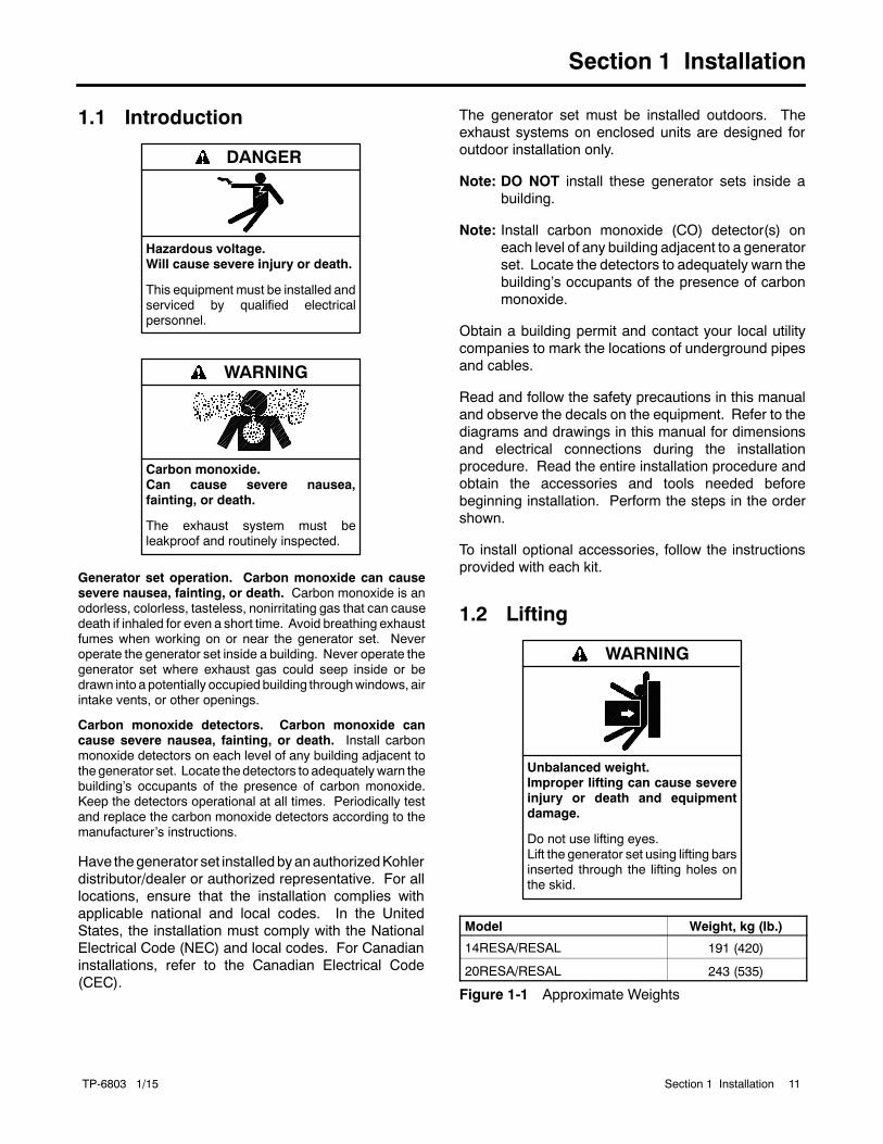
1.2 Lifting
Unbalanced weight.Improper lifting can cause severeinjury or death and equipmentdamage.
Do not use lifting eyes.Lift the generator set using lifting barsinserted through the lifting holes onthe skid.
WARNING
Model Weight, kg (lb.)
14RESA/RESAL 191 (420)
20RESA/RESAL 243 (535)
Figure 1-1 Approximate Weights

TP-6803 1/1512 Section 1 Installation
Approximate generator set weights are shown inFigure 1-1. Use lifting bars inserted through the holes inthe skid to lift the unit. See the dimension drawings inSection 2 for lifting hole locations.
1.3 Generator Set Inspection
Complete a thorough inspection of the generator set.Check for the following:
1. Inspect the generator set for loose or damagedparts or wires. Repair or tighten any loose partsbefore installation.
2. Check the engine oil. Fill, if necessary, with therecommended viscosity and grade of oil. Usesynthetic oil, API (American Petroleum Institute)Service Class SG or higher. See TP-6804,Operation Manual, for additional information.
1.4 Location and Mounting
Install the generator set outdoors near the incoming gasservice. The generator set location must allow easyaccess for maintenance and service. Therecommended distance from a structure is dependenton state and local codes. See the dimension drawing inSection 2 for the recommended clearance fromstructures and non-combustible materials.
Locate the generator set so that the hot exhaust doesnot blow on plants or other combustible materials. Noplants, shrubs, or other combustible materials areallowed within 1.2 m (4 ft.) of the exhaust end of thegenerator set.
Donot install the generator setwhere exhaust gas couldaccumulate and seep inside or be drawn into apotentially occupied building. Furnace and other similarintakes must be at least 3 m (10 ft.) from the exhaustend of the generator set.
NoticeDO NOT locate the generator set near patios,decks, play areas, or animal shelters. Keep itemssuch as lawn furniture, toys, sports equipment,and all combustible materials away from thegenerator set exhaust outlet.
Remind family members, children, and visitors touse caution near the generator set. Generatorsets connected to automatic transfer switchesstart automatically during exercise periods andpower outages. Some generator set componentsbecome hot when the generator set is running andremain hot for a time after the generator set shutsdown.
1.4.1 Mounting Area
The generator set is shipped on an engineeredcomposite mounting pad. Prepare a flat, level mountingarea covered with a weed barrier and gravel or aconcrete mounting pad. Set the composite mountingpad directly on the gravel or concrete.
Do not install the composite mounting pad directly ongrass, wood, or other combustible materials. Clear allcombustible materials, including plants and shrubs,building materials, and lawn furniture, from an area atleast 1.2 m (4 ft.) beyond the exhaust end of thegenerator set. See the dimension drawing in Section 2.
1.4.2 Concrete Mounting Pads
Kohler Co. offers optional concrete mounting pads thatare custom-designed for Model 14RESA/RESAL and20RESA/RESAL generator sets. Three-inch andfour-inch thick pads are available. Four-inch pads arerecommended for storm-prone areas. See TT-1619 forinstructions to install the mounting pad, if necessary.
1.4.3 Exhaust Requirements
Hot engine and exhaust system.Can cause severe injury or death.
Do not work on the generator set untilit cools.
WARNING

TP-6803 1/15 13Section 1 Installation
Figure 1-2 gives the exhaust temperature at rated load.The engine exhaust mixes with the generator setcooling air at the exhaust end of the enclosure. Mountthe generator set so that the hot exhaust does not blowon plants or other combustible materials. Maintain theclearances shown in the dimension drawing inSection 2.
ExhaustTemperature,_C (_F)
Exhaust gas exiting the enclosureat rated kW, _C (_F) 260 (500)
Figure 1-2 Exhaust Flow and Temperature
The generator set requires correct air flow for coolingand combustion. The inlet and outlet openings in thesound enclosure provide the cooling and combustionair. Figure 1-3 shows the locations of the cooling airintake and exhaust vents. Inspect the air inlet and outletopenings inside and outside the enclosure to ensurethat the air flow is not blocked.
tp6733
1. Air intake2. Exhaust outlet
1 21
REAR VIEW
Figure 1-3 Cooling Air Intake and Exhaust
The generator set is designed to operate with allenclosure panels and internal baffling in place. If duringinstallation, maintenance or repair the unit must beoperatedwithout the complete enclosureandbaffling asshipped from the factorymake sure the exhaust panel isremoved as well.
1.5 Dimension Drawings
See the dimension drawings in Section 2 for thegenerator set dimensions, fuel and electric inletlocations, and recommended clearance.
1.6 Access the Air Intake Area
The battery, fuel system, and electrical connections arelocated in the air intake area. Raise the roof and removethe enclosure panel to access the air intake area duringinstallation as described below.
1. Remove two screws from the top of the air intakepanel. Pull the the panel up and off. SeeFigure 1-4.
2. To make the electrical connections, you will alsoneed to remove the cover panel over the terminalblock as shown in Section 1.9.3.
3. Reinstall the panels after all electrical connectionsare complete and the battery is installed andconnected.
1. Remove 2 screws.ADV-8424
1
Figure 1-4 Removing the Air Intake Panel

TP-6803 1/1514 Section 1 Installation
1.7 Fuel Requirements
The generator set operates using natural gas or LPGfuel. The generator set is EPA-certified for both naturalgas and LPG fuels.
The fuel system installation must comply with the NECand local codes.
Explosive fuel vapors.Can cause severe injury or death.
Use extreme care when handling,storing, and using fuels.
WARNING
Explosive fuel vapors can cause severe injury or death.Take additional precautions when using the following fuels:
Propane (LPG)—Adequate ventilation is mandatory.Because propane is heavier than air, install propane gasdetectors low in a room. Inspect the detectors per themanufacturer’s instructions.
Natural Gas—Adequate ventilation is mandatory. Becausenatural gas rises, install natural gas detectors high in a room.Inspect the detectors per the manufacturer’s instructions.
1.7.1 Fuel Supply
Because of variable climates and geographicalconsiderations, contact the local fuel supplier for fuelsystem planning and installation. Figure 1-5 lists therecommended fuel ratings and other fuel supplyinformation for natural gas and LPG fuels.
Verify that the output pressure from the primary gasutility pressure regulator is within the range shown inFigure 1-5 and that the utility gas meter flow rate issufficient to supply the generator set at rated load plusall other gas-consuming appliances. For LPG tanks,verify that the output pressure is as shown in Figure 1-5.See Figure 1-6 for fuel consumption. Contact the fuelsupplier for flow rate information or a gas meterupgrade, if necessary.
Fuel typeNaturalGas LPG
Fuel supply inlet 1/2 NPT
Fuel supply pressure,kPa (in. H2O)
1.3--2.7(5--11)
1.7--2.7(7--11)
Fuel flow rate, maximum, Btu/hr.:
14RESA/RESAL 193,000 203,000
20RESA/RESAL 281,000 340,000
Nominal Fuel Rating, Btu/ft.3
Natural gas 1000
LPG 2500
Figure 1-5 Fuel Supply
Fuel Type % Load
Fuel Consumption, m3/hr. (cfh)
14RESA/RESAL 20RESA/RESAL
60 Hz 50 Hz 60 Hz 50 Hz
Natural Gas
100% 5.4 (193) 4.9 (175) 8.0 (281) 6.4 (225)
75% 4.7 (163) 4.2 (148) 6.9 (243) 5.4 (189)
50% 3.5 (124) 3.1 (108) 4.6 (161) 3.9 (139)
25% 2.6 (93) 2.4 (84) 3.6 (127) 2.9 (103)
LPG
100% 2.3 (81) 2.1 (74) 3.9 (136) 2.9 (102)
75% 2.1 (75) 1.9 (68) 3.1 (109) 2.4 (85)
50% 1.8 (60) 1.5 (53) 2.3 (82) 1.8 (63)
25% 1.2 (45) 1.1 (40) 1.7 (59) 1.3 (47)
LPG conversion factors:8.58 ft.3 = 1 lb.0.535 m3 = 1 kg36.39 ft.3 = 1 gal.
Nominal fuel rating:Natural gas: 37 MJ/m3 (1000 Btu/ft.3)LPG: 93 MJ/m3 (2500 Btu/ft.3)
Figure 1-6 Fuel Consumption
TP-6803 1/15 15Section 1 Installation
1.7.2 Fuel Pipe Size
Ensure that the fuel pipe size and length meet thespecifications in Figure 1-7. Measure the pipe lengthfrom the primary gas pressure regulator to the pipeconnection on the generator set fuel inlet. Add 2.4 m(8 ft.) to themeasured length for each 90 degree elbow.Compare the total pipe length with the chart inFigure 1-7 to find the required pipe size.
Contact local LPG provider for LPG installationinformation.
Minimum Gas Pipe Size Recommendation, in. NPT
PipeLength,m (ft.)
14RESA/RESAL 20RESA/RESAL
NaturalGas
(193,000Btu/hr.)
LPG(203,000Btu/hr.)
NaturalGas
(281,000Btu/hr.)
LPG(340,000Btu/hr.)
8 (25) 3/4 3/4 1 3/4
15 (50) 1 3/4 1 1
30 (100) 1 1 1 1/4 1
46 (150) 1 1/4 1 1 1/4 1 1/4
61 (200) 1 1/4 1 1 1/4 1 1/4
Figure 1-7 Fuel Pipe Size Recommendations
1.7.3 Connecting the Fuel Supply
The dimension drawing in Section 2 shows the locationof the fuel inlet connection. Have the fuel supplier installrigid gas piping and a manual fuel shut-off valve. Thefuel supply line should line upwith the generator set fuelinlet and end about 12 inches away to allow connectionwithasectionof flexible fuel line. Use flexible sections toprevent fuel line breakage caused by vibration.
Note: Do not bend the flexible fuel line to make up formisalignment of the fuel supply line and thegenerator set fuel inlet.
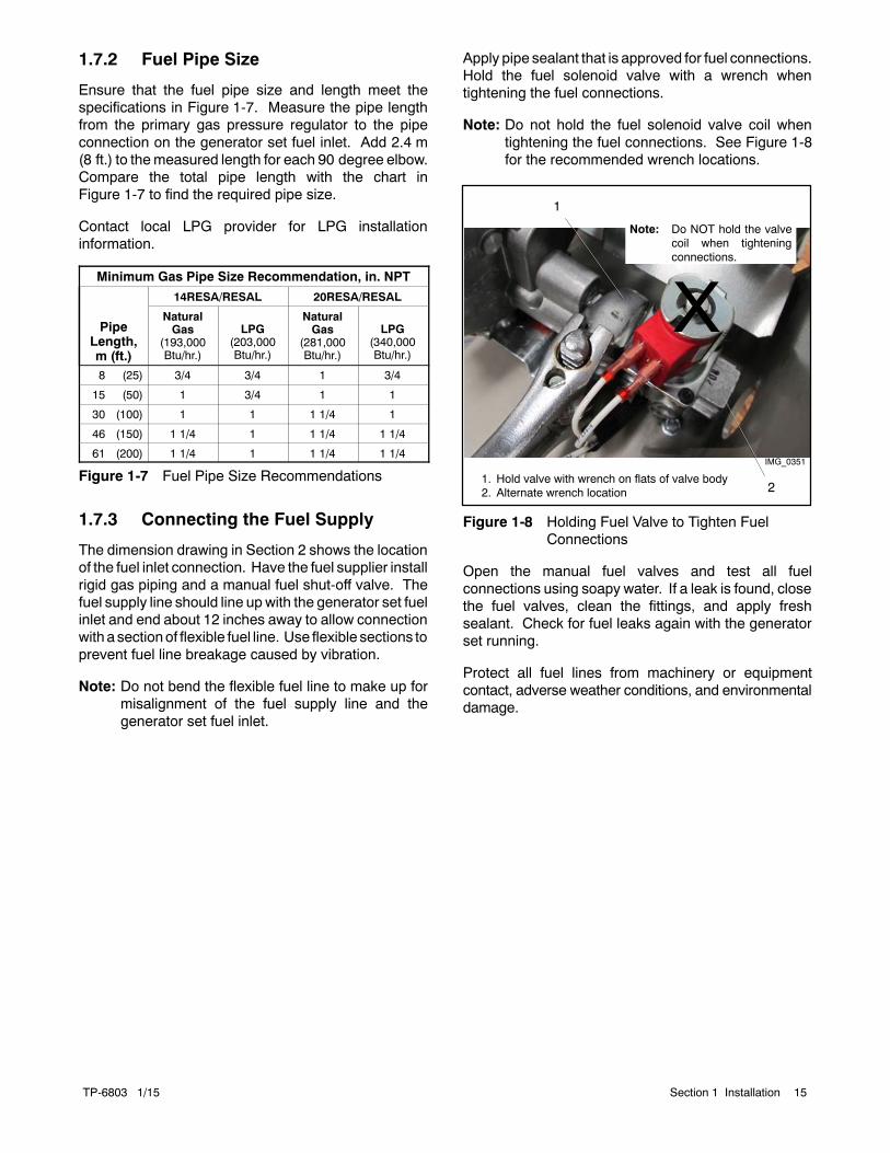
Apply pipe sealant that is approved for fuel connections.Hold the fuel solenoid valve with a wrench whentightening the fuel connections.
Note: Do not hold the fuel solenoid valve coil whentightening the fuel connections. See Figure 1-8for the recommended wrench locations.
2
IMG_0351
1. Hold valve with wrench on flats of valve body2. Alternate wrench location
1
Note: Do NOT hold the valvecoil when tighteningconnections.
Figure 1-8 Holding Fuel Valve to Tighten FuelConnections
Open the manual fuel valves and test all fuelconnections using soapy water. If a leak is found, closethe fuel valves, clean the fittings, and apply freshsealant. Check for fuel leaks again with the generatorset running.
Protect all fuel lines from machinery or equipmentcontact, adverse weather conditions, and environmentaldamage.

TP-6803 1/1516 Section 1 Installation
1.8 Fuel Conversion
The multi-fuel system allows conversion from naturalgas to LPG (or vice-versa) in the field while maintainingemissions-standard compliance. A trained technicianor an authorized distributor/dealer can convert the fuelsystem.
After converting the fuel system, change the Fuel Typesetting on the controller. See the Operation Manual forinstructions to change settings at the controller, or use apersonal (laptop) computer and Kohlerr SiteTechtsoftware to change the setting.
Rating Change
Converting the fuel will change the generator set rating.See thegenerator set specification sheet for ratingswithnatural gas and LP. Order a new nameplate with theupdated rating and fuel information from an authorizeddistributor/dealer, if necessary. Provide the followinginformation from the original nameplate:
D Model Number D kVAD Spec Number D AmpsD Serial Number D VoltsD Fuel (original and new) D HzD kW
Attach the new nameplate over the old one. Do NOTcover the UL listing information on the old nameplate.
Accidental starting.Can cause severe injury or death.
Disconnect the battery cables beforeworking on the generator set.Remove the negative (--) lead firstwhen disconnecting the battery.Reconnect the negative (--) lead lastwhen reconnecting the battery.
WARNING
Disabling the generator set. Accidental starting cancause severe injury or death. Before working on thegenerator set or equipment connected to the set, disable thegenerator set as follows: (1) Press the generator set off/resetbutton to shut down the generator set. (2) Disconnect thepower to the battery charger, if equipped. (3) Remove thebattery cables, negative (--) lead first. Reconnect the negative(--) lead last when reconnecting the battery. Follow theseprecautions to prevent the starting of the generator set by theremote start/stop switch.
Explosive fuel vapors.Can cause severe injury or death.
Use extreme care when handling,storing, and using fuels.
WARNING
Explosive fuel vapors can cause severe injury or death.Take additional precautions when using the following fuels:
Propane (LPG)—Adequate ventilation is mandatory.Because propane is heavier than air, install propane gasdetectors low in a room. Inspect the detectors per themanufacturer’s instructions.
Natural Gas—Adequate ventilation is mandatory. Becausenatural gas rises, install natural gas detectors high in a room.Inspect the detectors per the manufacturer’s instructions.
1.8.1 Fuel Conversion, 14RESA/RESALEquipped with Fuel Block
Note: Model 14RESA/RESAL generator sets builtbefore June 26, 2014 use a fuel block for the fueltype selection. See Figure 1-9 and use theinstructions in this section for fuel conversion.
Model 14RESA/RESALgenerators built June26,2014, or later are not equippedwith the fuel block.These units use fuel orifice fittings installed in thehose fitting at the fuel regulator. See Section1.8.2 for fuel conversion instructions.
Two fuel connections on the fuel block allow field-conversion between natural gas and LPG. The fuelmetering valves are factory-set and sealed to complywith applicable emission standards and to provide thebest possible hot and cold starting.
Note: Do not adjust the factory-sealed fuel-meteringadjustments on the fuel block. Changing the fuel-meteringadjustmentsmayviolate federal or statelaws.
Use the following procedure to convert from natural gas(NG) to LPG. See Figure 1-9 for the fuel systemcomponent locations.

TP-6803 1/15 17Section 1 Installation
Procedure to convert from NG to LPG,14RESA/RESAL with fuel block
1. Press the OFF button on the generator setcontroller.
2. Disconnect the power to the battery charger.
3. Disconnect the generator set engine startingbattery, negative (--) lead first.
4. Turn off the fuel supply.
5. Remove the hose clamp and fuel hose from thehose fitting in the fuel block. See Figure 1-9.
6. Remove the hose fitting from the natural gas outletport in the fuel block. See Figure 1-9.
7. Remove the plug from the LP port in the fuel block.See Figure 1-9.
8. Clean the plugwith a dry cloth or brush, apply freshpipe sealant, and install the plug into the naturalgas outlet port.
9. Clean the hose fitting with a dry cloth or brush,apply fresh pipe sealant to the threads, and installthe fitting into the LP port.
Note: Do not adjust the fuel metering valves.
10. Slide the hose onto the hose fitting and secure itwith the clamp.
11. Disconnect digital spark-advance ignition (DSAI)leads 65 and N3 for LPG. The DSAI leads arelocated near the fuel solenoid valve. SeeFigure 1-9.
12. Connect and turn on the new fuel supply.
13. Reconnect the generator set engine startingbattery leads, negative (--) lead last.
14. Reconnect power to the battery charger.
15. Start the generator set by pressing the RUNbuttonon the generator set controller.
16. Check for leaks using a gas leak detector.
17. Run the generator set and check the operation.
18. Press theOFFbutton to to shut down thegeneratorset.
Conversion from LPG to Natural Gas
To convert from LPG to natural gas, follow the fuelconversion procedure above, moving the hose fitting tothe natural gas port and plugging the LP port. Connectthe DSAI leads for natural gas. See Figure 1-9.
9
photo223
1. Fuel block (14RES only)2. Fuel metering valves—factory-sealed, do not adjust3. Fuel solenoid valve coil4. Fuel inlet, 1/2 in. NPT5. DSAI leads 65 and N36. Recommended holding points for tightening fuel connection7. Fuel regulator8. Ports are labeled LP and NG9. Plug10. Hose fitting
1 2
4
10 LPG setupshown
5
3
6
DSAI Lead Connection
7
8
Figure 1-9 Fuel System, 14RESA/RESAL Equippedwith Fuel Block (built before June 26,2014)

TP-6803 1/1518 Section 1 Installation
1.8.2 Fuel Conversion, 14RESA/RESALEquipped with Fuel OrificeFittings
Note: Model 14RESA/RESAL generator sets builtbefore June 26, 2014, use a fuel block for the fueltype selection. See Figure 1-9 and use theinstructions Section 1.8.1 for fuel conversion.
Model 14RESA/RESALgenerators built June 26,2014, or later are not equippedwith the fuel block.These units use fuel orifice fittings installed in thehose fitting at the fuel regulator. See Figure 1-11and use the instructions in this section for fuelconversion.
For natural gas and LPG fuel, orifice fittings are used inthe fuel line. See Figure 1-10. The natural gas orificefitting is silver in color and stamped NG. The LPG fittingis gold in color and stamped LPG. The fittings arethreaded. A straight-blade screwdriver is required toremove and replace the fittings.
NG LPG
Figure 1-10 NG and LPG Fuel Orifice Fittings
The unit is typically shipped set up for natural gas, withthe LPG fitting tied near the fuel solenoid valve. Toconvert to LPG, remove the NG fitting and install theLPG fitting as described below. See Figure 1-11 for thefuel system component locations.
Procedure to Convert from NG to LPG,14RESA/RESAL with fuel orifice fittings
1. Press the OFF button on the generator setcontroller.
2. Disconnect the utility power to the generator.
3. Disconnect the generator set engine startingbattery, negative (--) lead first.
4. Turn off and disconnect the fuel supply.
5. Remove the hose clamp and fuel hose from thehose fitting. See Figure 1-11.
3
1. LPG fitting tied to bracket for shipping2. Fuel hose and clamp3. DSAI Leads
1 2
DSAI Lead Connection
Figure 1-11 Fuel System, As Shipped (Model14RESA/RESAL built after June 26,2014)
6. Use a straight-blade screwdriver to remove theNGorifice from the hose fitting. See Figure 1-12.
7. Insert the LPG orifice into the hose fitting. Use astraight-blade screwdriver to tighten the fitting untilit is snug.
8. Slide the hose onto the hose fitting and secure itwith the clamp.
9. Disconnect digital spark-advance ignition (DSAI)leads 65 and N3 for LPG. The DSAI leads are

TP-6803 1/15 19Section 1 Installation
located near the fuel solenoid valve. SeeFigure 1-11.
10. Connect and turn on the new fuel supply.
11. Reconnect the generator set engine startingbattery leads, negative (--) lead last.
12. Reconnect the utility power to the generator.
13. Start the generator set by pressing the RUNbuttonon the generator set controller.
14. Check for leaks using a gas leak detector.
15. Run the generator set and check the operation.
16. Press the OFF button to shut down the generatorset.
Conversion from LPG to Natural Gas
To convert from LPG to natural gas, repeat the stepsabove, removing the LPG fuel orifice and installing theNG fitting. Connect DSAI leads 65 and N3 together fornatural gas.
2
GM841431. Orifice fitting (see detail)2. Hose barb fitting
ORIFICE FITTING DETAIL
1
Figure 1-12 14RESA/RESAL Fuel System Showing Orifice Fittings (generators built after June 26, 2014)

TP-6803 1/1520 Section 1 Installation
1.8.3 Fuel Conversion, 20RESA/RESAL
For LPG fuel, anorifice is used in the fuel line. Theunit istypically shipped set up for natural gas, with the looseorifice tied near the fuel solenoid valve. To convert toLPG, install the LPG orifice as described below. SeeFigure 1-13 for the fuel system component locations.
Note: The generator set harness may contain a pair ofDSAI leads near the fuel solenoid valve.Connecting or disconnecting these leads has noeffect on the 20RESA/RESAL operation.
Procedure to Convert from NG to LPG,20RESA/RESAL
1. Press the OFF button on the generator setcontroller.
2. Disconnect the power to the battery charger.
3. Disconnect the generator set engine startingbattery, negative (--) lead first.
4. Turn off the fuel supply.
5. Remove the hose clamp and fuel hose from thehose fitting. See Figure 1-13.
6. Insert the LPG orifice into the hose fitting. SeeFigure 1-13.
7. Slide the hose onto the hose fitting and secure itwith the clamp.
8. Connect and turn on the new fuel supply.
9. Reconnect the generator set engine startingbattery leads, negative (--) lead last.
10. Reconnect power to the battery charger.
11. Start the generator set by pressing the RUNbuttonon the generator set controller.
12. Check for leaks using a gas leak detector.
13. Run the generator set and check the operation.
14. Press the OFF button to shut down the generatorset.
Conversion from LPG to Natural Gas
To convert from LPG to natural gas, repeat the stepsabove to remove the LPG fuel orifice.
1. LPG orifice2. Hose fitting3. Regulator4. Regulator vent tubes (vent to the outside of the controller)
GM84143
3
1
LPG setupshown
2
4
Figure 1-13 Fuel Regulator and LPG Orifice,20RESA/RESAL
1.8.4 Regulator Vent Hose
Model 20RESA/RESAL generators are equipped withfuel regulator vent hoses. Drill or punch two holes in theenclosure at the locations shown on the template inAppendixB. Itmaybeconvenient to cut openings for theelectrical leads at the same time as shown on thetemplate and in Section 1.9.2.
Insert the open ends of the hoses through the holes tothe outside of the enclosure as shown in Figure 1-14.
1. Fuel regulator vent tubes, qty. 22. Drill or punch two holes and route both hoses to the outside
of the enclosure
2
sb722
1
Figure 1-14 Fuel Regulator Vent Hoses

TP-6803 1/15 21Section 1 Installation
1.9 Electrical Connections
Hazardous voltage.Will cause severe injury or death.
This equipment must be installed andserviced by qualified electricalpersonnel.
DANGER
Grounding electrical equipment. Hazardous voltage cancause severe injury or death. Electrocution is possiblewhenever electricity is present. Ensure you comply with allapplicable codes and standards. Electrically ground thegenerator set, transfer switch, and related equipment andelectrical circuits. Turn off the main circuit breakers of allpower sources before servicing the equipment. Never contactelectrical leads or appliances when standing inwater or onwetground because these conditions increase the risk ofelectrocution.
Electrical backfeed to the utility. Hazardous backfeedvoltage can cause severe injury or death. Install a transferswitch in standby power installations to prevent the connectionof standby and other sources of power. Electrical backfeedinto a utility electrical system can cause severe injury or deathto utility personnel working on power lines.
NOTICECanadian installations only. For standby service connectthe output of the generator set to a suitably rated transferswitch in accordance with Canadian Electrical Code, Part 1.
Have an authorized distributor/dealer or a licensedelectrician make the following electrical connections.The electrical installation must comply with the NationalElectrical Coder (NEC) class 1 wire designation and allapplicable local codes. Canadian installations mustcomply with the Canadian Electrical Code (CEC) andapplicable local codes.
AC circuit protection. All AC circuits must includecircuit breaker or fuse protection. The circuit breakermust be rated for a maximum of 125% of the ratedgenerator set output current. The circuit breaker mustopen all ungrounded connectors. The generator set isequipped with a factory-installed circuit breaker.
For customer-supplied wiring, select the wiretemperature rating in Figure 1-15 based upon thefollowing criteria:
D Select row 1, 2, 3, or 4 if the circuit rating is110 amperes or less or requires #1 AWG (42.4 mm2)or smaller conductors.
D Select row 3 or 4 if the circuit rating is greater than110 amperes or requires #1 AWG (42.4 mm2) orlarger conductors.
Row Temp. Rating Copper (Cu) Only Cu/Aluminum (Al) Combinations Al Only
1 60_C (140_F)or
75_C (167_F)
Use No. * AWG, 60_C wire oruse No. * AWG, 75_C wire
Use 60_C wire, either No. * AWG Cu, or No. *AWG Al or use 75_C wire, either No. * AWGCu or No. * AWG Al
Use 60_C wire, No. * AWG oruse 75_C wire, No. * AWG
2 60_C (140_F) Use No. * AWG, 60_C wire Use 60_C wire, either No. * AWG Cu or No. *AWG Al
Use 60_C wire, No. * AWG
3 75_C (167_F) Use No. *[ AWG, 75_C wire Use 75_C wire, either No. *[ AWG Cu or No.*[ AWG Al
Use 75_C wire, No.*[ AWG
4 90_C (194_F) Use No. *[ AWG, 90_C wire Use 90_C wire, either No. *[ AWG Cu or No.*[ AWG Al
Use 90_C wire, No.*[ AWG
* The wire size for 60_C (140_F) wire is not required to be included in the marking. If included, the wire size is based on ampacities for thewire given in Table 310-16 of the National Electrical Coder, in ANSI/NFPA 70, and on 115% of the maximum current that the circuit carriesunder rated conditions. The National Electrical Coder is a registered trademark of the National Fire Protection Association, Inc.
[ Use the larger of the following conductors: the same size conductor as that used for the temperature test or one selected using theguidelines in the preceding footnote.
Figure 1-15 Terminal Markings for Various Temperature Ratings and Conductors
The National Electrical Coder is a registered trademark of the National Fire Protection Association, Inc.

TP-6803 1/1522 Section 1 Installation
1.9.1 Grounding
Ground the generator set. The grounding methodmust complywithNECand local codes. Connect thegrounding cable to the generator set ground terminalGND on the field-connection terminal block.
Generator sets are shipped with the generator neutralbonded (connected) to the generator ground in thejunction box. The requirement for having a bonded(grounded) neutral or ungroundedneutral is determinedby the type of installation. At installation, the neutral canbe grounded at the generator set or lifted from theground stud and isolated if the installation requires anungrounded neutral connection at the generator. Thegenerator setwill operateproperlywith theneutral eitherbonded to ground or isolated from ground at thegenerator.
Various regulationsandsite configurations including theNational Electrical Code (NEC), local codes, and thetype of transfer switch used in the application determinethe grounding of the neutral at the generator. NECSection 250 is one example that has a very goodexplanation of the neutral grounding requirements forgenerators.
1.9.2 Electrical Lead Entry
Drill or punch holes in the enclosure for the electricalconduit in the locations shown in Figure 1-16. Afull-scale dimensioned template for the hole locations isprinted in Appendix B. See page 57.
4
ADV--8424
1. Optional emergency stop switch location. Do not use toroute wiring.
2. Utility voltage electrical lead entry point3. ATS signal electrical lead entry point4. 1/2 NPT female fuel inlet
2
3
1
Note: See Appendix B for a full-scale templatewith dimensions.
Figure 1-16 Electrical Lead Entry Locations
1.9.3 Field-Connection Terminal Block
The generator set is equipped with a field-connectionterminal block located in the air intake area near thejunction box. Leads have been factory-installed fromthe junction box to the terminal block for easy fieldwiring.
See Figure 1-17 for the terminal block location.Remove the cover panel for access to the fieldconnections.
1
adv-8424
1. Cover panel. Remove for access to field-connection terminalblock.
Figure 1-17 Field-Connection Terminal BlockLocation

TP-6803 1/15 23Section 1 Installation
See Figure 1-18 for terminal block details. Refer to theterminal block decal shown in Figure 1-19 forconnections and cable sizes. Also see the wiringdiagram in Section 2.
Route AC leads through flexible conduit. Ensure thatthe leads and conduit do not interfere with the operationof the generator set or obstruct the service areas. Routelow-voltage communication leads through separateconduit.
Procedure
1. Drill holes for the conduit fittings. See Figure 1-16and Appendix B for the recommended electricalinlet locations. Feed the cables through theopenings.
2. Connect the leads from the transfer switchemergency source lugs to the L1, L2, and L3connections on the generator set terminal block asapplicable for single or three-phase applications.See Figure 1-18 and Figure 1-19.
3. Connect the neutral (L0) and ground (GRD) leadsfrom the ATS and the main panel to thecorresponding connection points on the terminalblock. See Section 1.9.1, Grounding.
4. Connect AC power source leads to the terminalblock connections labeled LINE, NEUTRAL andGROUND. Connect the circuit to the load side ofthe transfer switch. See Section 1.9.4 for moreinformation about the AC power requirement.
Note: AC power must be connected to maintainthe charge on the engine starting battery.
5. For connection of optional transfer switches, theprogrammable interface module (PIM), and/or aload control module (LCM) or load shed kit, seeSection 1.10.1.
6. If the OnCuer Plus Generator ManagementSystem will be used with the generator set, runcategory 5E network cable from the generator setto the customer’s router or modem.
Note: The OnCue Plus Wireless kit allowsconnection of the generator controller to thecustomer’swireless routerwithout runninganetwork cable from the generator to thecustomer’s router or modem. If the OnCuePlusWireless is used, follow the instructionsprovided with the kit to install and set up thewireless kit and proceed to step 7.
a. Route the network cable with other low-voltagesignal wiring (for example, the RBUScommunication leads or engine start leads tothe transfer switch), in separate conduit fromtheAC load leads. If thenetwork cable is longerthan 100 meters (328 ft.), use a repeater orswitch.
b. Use an RJ45 inline coupler to connect theEthernet cable to the cable in the customerconnection box. See Figure 1-18. The inlinecoupler is included with the OnCue Plus kit.
7. When connections to the terminal block arecomplete, replace the cover plate.
1. Low voltage RBUS communication to RXT ATS, PIM, LCMor load shed kit, and/or APM.
2. Engine start connections from transfer switches other thanthe RXT, if used.
3. Ground connection for communication cable shield4. Ethernet cable for optional OnCue Plus connection5. AC load connections6. AC power connections required for battery charging and
accessories7. Connection decal; see Figure 1-19.
GM84094
5
26
3
4
Note: The number of terminals varies for 1-phaseand 3-phase models. See Figure 1-19.
7
1
Figure 1-18 Field Connection Terminal Blocks

TP-6803 1/1524 Section 1 Installation
1-Phase, 1-Pole Circuit Breaker
1-Phase, 2-Pole Circuit Breaker
3-Phase
Figure 1-19 Terminal Block Connection Decals
1.9.4 AC Power Supply
The installer must connect AC power for the batterycharger (which is integral to the RDC2 controller) andthe optional accessories shown in Figure 1-20. Thepower source must comply with state and local codes.The power to the battery charger and accessories mustbe backedupby the generator so that power is availableat all times.
Be sure to disconnect power at the distribution panelbeforemaking theconnections. Connect power leads tothe AC power connection points labeled LINE,NEUTRAL, and GROUND on the field-connectionterminal block. Connect the circuit to the load side of thetransfer switch so that it is backed up by the generator.SeeFigure 1-18 and thewiringdiagrams inSection 2 forconnection details.
Equipment
Power Requirement, Max.
Watts Volts at 50/60 Hz
Battery charger(standard)
50 100--120 VAC
50 200--250 VAC
Carburetor heater(optional)
37 100--120 VAC
37 200--250 VAC
Battery heater (optional) 50 100--120 VAC
50 200--250 VAC
Fuel regulator heater(optional; available for20RESA/RESAL only)
60 100--120 VAC
100 200--250 VAC
Figure 1-20 Power Requirements
TP-6803 1/15 25Section 1 Installation
1.10 ATS and AccessoryConnections
The following sections cover electrical connections ofthe automatic transfer switchesandRBUSaccessories,including theprogrammable interfacemodule (PIM)andthe load control module (LCM) or load shed kit.
1.10.1 Transfer Switch Connection
Connect the ATS or remote start/stop switch. Connectthe load leads from the generator set to the Emergencysource lugs on the ATS. Route low-voltagecommunication leads throughseparate conduit from theAC power and load leads. All connections must complywith applicable state and local codes.
Note: Do not use the Kohlerr Model RRT transferswitch with the 14/20RESA or 14/20RESALgenerator set.
Communication connections for a KohlerrModel RXT transfer switch
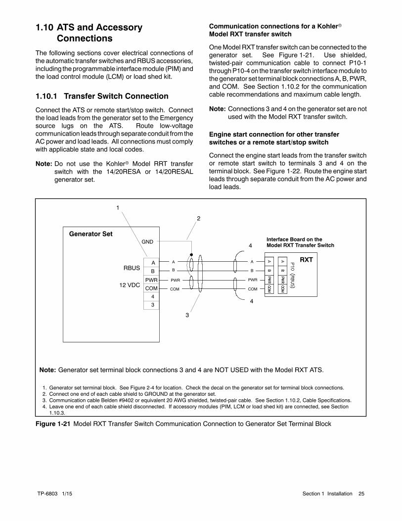
OneModel RXT transfer switch can be connected to thegenerator set. See Figure 1-21. Use shielded,twisted-pair communication cable to connect P10-1throughP10-4on the transfer switch interfacemodule tothegenerator set terminal block connectionsA,B,PWR,and COM. See Section 1.10.2 for the communicationcable recommendations and maximum cable length.
Note: Connections 3 and 4 on the generator set are notused with the Model RXT transfer switch.
Engine start connection for other transferswitches or a remote start/stop switch
Connect the engine start leads from the transfer switchor remote start switch to terminals 3 and 4 on theterminal block. See Figure 1-22. Route the engine startleads through separate conduit from the AC power andload leads.
1. Generator set terminal block. See Figure 2-4 for location. Check the decal on the generator set for terminal block connections.2. Connect one end of each cable shield to GROUND at the generator set.3. Communication cable Belden #9402 or equivalent 20 AWG shielded, twisted-pair cable. See Section 1.10.2, Cable Specifications.4. Leave one end of each cable shield disconnected. If accessory modules (PIM, LCM or load shed kit) are connected, see Section
1.10.3.
Interface Board on theModel RXT Transfer Switch
Note: Generator set terminal block connections 3 and 4 are NOT USED with the Model RXT ATS.
Generator Set
B
A RXT
COM
PWR
B
A
GND
A
B
COM
PWR
3
4
RBUS
12 VDC
3
1
2
4
4
COM
PWR
Figure 1-21 Model RXT Transfer Switch Communication Connection to Generator Set Terminal Block

TP-6803 1/1526 Section 1 Installation
tp6803
1. Generator Set Terminal Block. See the dimension drawings in Section 2 for location. Check the decal on the generator set for terminalblock connections.
2. Engine start leads 3 and 4. See the ATS manual for cable size specifications.
Generator Set
ATS(with enginestart contacts)
A
B
COM
PWR
3
4
1
2
Figure 1-22 Engine Start Connections with Transfer Switch Models other than Model RXT
1.10.2 Communication CableSpecifications
RBUS Connections A and B
For the RBUS communication connections A and B tothe Model RXT transfer switch, optional PIM and/oroptional LCM or load shed kit, use 20 AWG shielded,twisted-pair communication cable. Belden #9402(two-pair) or Belden #8762 (single-pair) or equivalentcable is recommended.
For outdoor installations, including those with buriedcables and/or conduit, use outdoor-rated Belden#1075A or equivalent 20 AWG shielded, twisted-paircommunication cable.
PWR and COM Connections
For the PWR and COM connections, the cable size andmaximum cable length depends on the number ofmodules connected. See Figure 1-23.
D For short cable runs shown in the first two rows ofFigure 1-23, use one pair in the two-paircommunication cable for the A and B connections,
and use the second pair for the PWR and COMconnections.
D For the longer cable runsshown in the last two rowsofFigure 1-23, use 12 or 14 AWG cable for PWR andCOM, and use the 20 AWG communication cablespecified above for the A and B connections only. Inthis case, single-pair communication cable such asBelden #8762 can be used for the A and Bconnections.
1.10.3 System Connections withAccessory Modules
See Figure 1-24 through Figure 1-28 for connectionoptions with accessory modules. Accessory modulescan include one Model RXT transfer switch, oneprogrammable interface module (PIM) and/or one loadcontrol module (LCM) or load shed kit. Note the cableshield connections shown in Figure 1-24.
The maximum cable length depends on the number ofoptional modules connected. See Figure 1-23 for themaximumcable lengthswith1, 2, or 3modulesper cablerun.

TP-6803 1/15 27Section 1 Installation
Cable Size for PWR and COM Connections
Indoor orOutdoor
Installation
Maximum length per run, meters (ft.)
Number of Modules per Run
1 Module 2 Modules 3 Modules
20 AWG Belden #9402 or equivalent, two-pair Indoor 61 (200) 31 (100) 21 (67)
20 AWG Belden #1075A or equivalent, two-pair Outdoor 61 (200) 31 (100) 21 (67)
14 AWG * — 152 (500) 152 (500) 122 (400)
12 AWG * — 152 (500) 152 (500) 152 (500)
* Use 12 or 14 AWG cable for PWR and COM connections only. For RBUS connections A and B, use shielded, twisted pair communicationcable specified in Section 1.10.2.
Figure 1-23 Total Cable Lengths for PWR and COM Connections
RXT3
COM
PWR
B
A
4
PIM
LCMor loadshed kit
Generator Set
COM
COM
PWR
COM
PWR
PWR
B
A
B
A
B
A
COM
PWR
B
A
COM
PWR
B
A
1. Generator set terminal block. See Figure 2-4 for location. Check the decal on the generator set for terminal block connections.2. Connect one end of each cable shield to GROUND at the generator set.3. Communication cable Belden #9402 or equivalent 20 AWG shielded, twisted-pair cable.4. Connect shields together as shown.5. Leave one end of each cable shield disconnected at the last device.
GND
Note: See Section 1.10.2, Cable Specifications.
A
B
COM
PWR
3
4
RBUS
12 VDC
1
2
5
5
Figure 1-24 Accessory Module Communication Connection Details

TP-6803 1/1528 Section 1 Installation
RXT3
COM
PWR
B
A
4
PIM
Generator Set
COM
COM
PWR
COM
PWR
PWR
B
A
B
A
B
A
COM
PWR
B
A
COM
PWR
B
A
1. Generator set terminal block. See Figure 2-4 for location. Check the decal on the generator set for terminal block connections.2. Connect one end of each cable shield to GROUND at the generator set.3. Communication cable Belden #8762 or equivalent 20 AWG shielded, twisted-pair cable (one pair).4. Connect shields together as shown.5. Leave one end of each cable shield disconnected at the last device.6. 12 AWG or 14 AWG leads for PWR and COM.
GND
A
B
COM
PWR
3
4
RBUS
12 VDC
1
2
5
6
Note: See Section 1.10.2, Cable Specifications.
LCMor loadshed kit
Figure 1-25 Accessory Module Connections with 12--14 AWG Power Leads

TP-6803 1/15 29Section 1 Installation
tp6803
PIM
RXT ATSGenerator Set
Notes:
D See Figure 2-4 for terminal block location on generator set. Checkthe decal on the generator set for terminal block connections.
D See Section 1.10.2, Cable Specifications (3 runs with 1 moduleeach shown).
D See Figure 1-24 for communication connection detail (A and B,PWR and COM).
D Use splices or wire nuts to collect multiple leads for connection tothe generator set terminal block. See Figure 1-27.
TerminalBlock
LCMor loadshed kit
Figure 1-26 Accessory Module Connections (three cable runs with one module each)
2
tp6803
1. Generator Set Terminal Block. See the dimension drawings in Section 2 for location. Check the decal on the generator set for terminalblock connections.
2. Splice.3. Connect all of the shield leads on this end to GROUND at the generator set.
Generator SetCOMPWR
B
A
3
COM
PWR
BA
SHIELDEDCABLE
A
B
COM
PWR
3
4
RBUS
12 VDC
1
3
SHIELDEDCABLE
Figure 1-27 Multiple Connections to the Generator Set

TP-6803 1/1530 Section 1 Installation
tp6809
PIM
RXT ATSGenerator Set
Notes:
D See Figure 2-4 for terminal block location on generatorset. Check the decal on the generator set for terminalblock connections.
D See Section 1.10.2, Cable Specifications.
D See Figure 1-24 for communication connection detail (Aand B, PWR and COM). Connect the cable shield toground at the generator set.
D Use splices or wire nuts to collect multiple leads forconnection to the generator set terminal block. SeeFigure 1-27.
TerminalBlock
LCMor loadshed kit
Figure 1-28 Accessory Module Connections (two cable runs with one and two modules shown)
1.11 Battery
Sulfuric acid in batteries.Can cause severe injury or death.
Wear protective goggles andclothing. Battery acid may causeblindness and burn skin.
WARNING
Explosion.Can cause severe injury or death.Relays in the battery chargercause arcs or sparks.
Locate the battery in a well-ventilatedarea. Isolate the battery charger fromexplosive fumes.
WARNING
Battery electrolyte is a diluted sulfuric acid. Battery acidcan cause severe injury or death. Battery acid can causeblindness and burn skin. Always wear splashproof safetygoggles, rubber gloves, and boots when servicing the battery.Do not open a sealed battery or mutilate the battery case. Ifbattery acid splashes in the eyes or on the skin, immediatelyflush the affected area for 15 minutes with large quantities ofclean water. Seek immediate medical aid in the case of eyecontact. Never add acid to a battery after placing the battery inservice, as this may result in hazardous spattering of batteryacid.
Battery acid cleanup. Battery acid can cause severeinjury or death. Battery acid is electrically conductive andcorrosive. Add 500 g (1 lb.) of bicarbonate of soda (bakingsoda) to a container with 4 L (1 gal.) of water and mix theneutralizing solution. Pour the neutralizing solution on thespilled battery acid and continue to add the neutralizingsolution to the spilled battery acid until all evidence of achemical reaction (foaming) has ceased. Flush the resultingliquid with water and dry the area.

TP-6803 1/15 31Section 1 Installation
Battery gases. Explosion can cause severe injury ordeath. Battery gases can cause an explosion. Do not smokeor permit flames or sparks to occur near a battery at any time,particularly when it is charging. Do not dispose of a battery in afire. To prevent burns and sparks that could cause anexplosion, avoid touching the battery terminals with tools orother metal objects. Remove all jewelry before servicing theequipment. Discharge static electricity from your body beforetouching batteries by first touching a grounded metal surfaceaway from the battery. To avoid sparks, do not disturb thebattery charger connections while the battery is charging.Always turn the battery charger off before disconnecting thebattery connections. Ventilate the compartments containingbatteries to prevent accumulation of explosive gases.
Battery short circuits. Explosion can cause severe injuryor death. Short circuits can cause bodily injury and/orequipment damage. Disconnect the battery before generatorset installation or maintenance. Remove all jewelry beforeservicing the equipment. Use tools with insulated handles.Remove the negative (--) lead first when disconnecting thebattery. Reconnect the negative (--) lead last whenreconnecting the battery. Never connect the negative (--)battery cable to the positive (+) connection terminal of thestarter solenoid. Do not test the battery condition by shortingthe terminals together.
Connecting the battery and the battery charger.Hazardous voltage can cause severe injury or death.Reconnect the battery correctly, positive to positive andnegative to negative, to avoid electrical shock and damage tothe battery charger and battery(ies). Have a qualifiedelectrician install the battery(ies).
Starting batteries are usually the lead-acid type. Use a12-volt group 51 battery with a minimum rating of 500cold cranking amps at 0_F. The generator set uses anegative groundwith a 12-volt engine electrical system.See Figure 1-29 for battery connections. Make surethat the battery is correctly connected and the terminalsare tight.
Note: The generator set will not start and circuit boarddamage may occur if the battery is connected inreverse.
See the dimension drawing in Section 2 for the enginestarting battery location on the air intake side of thegenerator set. Standard battery cables provide easyconnection to the battery.
EZ-273000-J
1 2
1. To positive (+) terminal on starter solenoid.2. To ground (--) terminal on or near starter motor.
Figure 1-29 Typical Battery Connection
Use the following procedure to install and connect thebattery.
Battery Installation Procedure
1. Ensure that the starting battery is fully chargedbefore placing the battery in service.
2. Clean the battery posts and/or adapters ifnecessary.
3. Install the battery post adapters, if needed.
4. Place the battery in the housing.
5. Connect the positive (+) lead to the engine startingbattery.
6. Connect thenegative (--) lead to the engine startingbattery.
Refer to the generator set operation manual and thebattery manufacturer’s instructions for batterymaintenance instructions.
Whenpower is applied to theRDC2/DC2 controller (thatis, when the battery is connected), you will be promptedto set the date and time, and then to set the exerciser.See Section 1.14 and the generator set operationmanual for instructions.
If the battery is disconnected for service or replacement,the exercise settings on the RDC2/DC2 controller arelost. Set theexerciser after installingandconnecting thebattery. See Section 1.14, Set Exerciser.

TP-6803 1/1532 Section 1 Installation
1.12 Generator Set Accessories
This section describes some of the accessories that areavailable for the generator sets. Have accessoriesinstalled by an authorized distributor/ dealer or alicensed electrician. This document does not containinstallation instructions for accessories. Follow theinstallation instructions provided with each kit.
Use separate conduit for ACandDC leads to reduce thepossibility of electrical interference. Verify that the leadsand conduit do not interfere with the operation of thegenerator set or obstruct the service areas. Verify thatthe electrical installation complies with the NationalElectrical Code (NEC) and all applicable local codes.See the wiring diagrams in Section 2 for moreinformation regarding generator set electricalconnections.
1.12.1 Programmable Interface Module(PIM)
The optional programmable interface module (PIM)provides two programmable inputs and six dry contactoutputs, four of which are programmable. See TT-1584for PIM installation and connection instructions. Alsosee Section 1.10 of this manual for connection to thegenerator set.
The default settings for the inputs and outputs areshown in Figure 1-31. To change the input and outputsettings, use a personal computer running KohlerSiteTechr software. See TP-6701, SiteTech SoftwareOperation Manual, for instructions.
KohlerOnCuerPlus can be used to actively control PIMoutputs. See the OnCue Plus Operation Manual forinstructions.
1. Output connections (3 terminal blocks, 6 outputs)2. Input connections (2 inputs)3. RBUS communication connection to generator set terminal
block TB2
2
ADV-8199
1
3
1
1
Figure 1-30 Optional PIM
PIM Connection Factory Default Setting
Input 1 None
Input 2 None
Output 1 (Relay 1) Run
Output 2 (Relay 2) Common Fault
Output 3 (Relay 3) Low Battery Voltage(Programmable)
Output 4 (Relay 4) Not in Auto (Programmable)
Output 5 (Relay 5) Cooldown (Programmable)
Output 6 (Relay 6) Normal Source Failure(Programmable)
Figure 1-31 PIM Inputs and Outputs

TP-6803 1/15 33Section 1 Installation
1.12.2 Load Control Module (LCM)
The optional LoadControlModule (LCM) is available forsingle-phase generator sets only. The LCM providesan automatic load management system to comply withSection 702.5 of NEC2008. The installer is responsiblefor ensuring that the power system installation complieswith all applicable state and local codes.
With the Load Control Module (LCM), less criticalappliances can be powered by the generator set whenthemore important appliances are not running, allowingthe use of a smaller generator set thanwould be neededto run all of the building’s electrical equipment at thesame time.
The LCM receives commands from the RDC2 or DC2generator controller and energizes or de-energizes theappropriate load relays to add or shed non-critical loadsaccording to their priority.
Note: Connect only non-essential loads to the loadcontrol module.
The load control module automatically manages up tosix residential loads:
D Four power relays are provided for management ofnon-essential secondary loads. 120VACpowermustbe provided for operation of the power relays.
D Two relays are available to control two independentair conditioner loads.
The LCM is available with either a prewired harness forload relay connection, or a terminal block. The prewiredharness requires installation of the LCM within0.6 meters (2 feet) of the distribution panel. The loadcontrol module with the optional wire harness is shownin Figure 1-32. If the harness is not used, connect to theterminal blocks inside the LCM enclosure. Figure 1-33shows the load control module without the optionalharness.
Refer to TT-1574, providedwith the LCM, for installationand connection instructions.
Figure 1-32 Optional Load Control Module (LCM)(shown with optional pre-wired harness)
1
1. Load control circuit board2. Power relays3. Customer connection to power relays4. 120 VAC power supply connection
2
3
4
Figure 1-33 Load Control Module (cover removed toshow field-connection terminal blocks)

TP-6803 1/1534 Section 1 Installation
1.12.3 Load Shed Kit
An optional load shed kit can be used on single-phasesystems that include a Model RDT or RXT transferswitch. The load shed kit mounts inside the Model RDTor RXT transfer switch enclosure. Figure 1-34 showsthe load shed assembly.
The load shed kit provides an automatic loadmanagement system to comply with Section 702.5 ofNEC 2008. The installer is responsible for ensuring thatthe power system installation complies with allapplicable state and local codes.
Note: Do not install both a load shed kit and a loadcontrol module (LCM) on the same system.
The load shed kit provides the same load shed and addfunctions as the load control module (LCM). SeeSection 1.12.2.
Note: Connect only non-essential loads to the loadshed kit.
The load shed kit automatically manages up to sixresidential loads:
D Up to four customer-supplied power relays can beconnected through normally open relay contacts onthe circuit board. See TT-1609 for relay coil voltagespecifications.
D Two relays are included to control two independentheating, ventilation, and air conditioning (HVAC)loads.
An adequate electrical supply is required for operationof the customer-supplied power relays connected to theload shed kit. Check the electrical requirements of thecustomer-provided equipment prior to installation todetermine the wire size and circuit protection required.Verify that customer-provided equipment complies withapplicable local and national electrical codes.
See TT-1609, provided with the kit, for detailedinstallation and connection instructions.
1. Terminal block TB102. Load control circuit board3. Mounting bracket
Note: Kit includes current transformer (CT), not shown.
2
GM88281
1
3
Figure 1-34 Load Shed Assembly GM88281-1(mounts inside the transfer switchenclosure)

TP-6803 1/15 35Section 1 Installation
1.12.4 Regulator Heater
Hot engine and exhaust system.Can cause severe injury or death.
Do not work on the generator set untilit cools.
WARNING
Servicing the engine heater. Hot parts can cause minorpersonal injury or property damage. Install the heaterbefore connecting it to power. Operating the heater beforeinstallation can cause burns and component damage.Disconnect power to the heater and allow it to cool beforeservicing the heater or nearby parts.
The optional regulator heater kit is designed for Model20RESA and 20RESAL generator sets. The regulatorheater kit is recommended in addition to the carburetorheater for reliable engine starting in temperatures below--18_C (0_F). See Figure 1-35 for heater specifications.Order the 120 V or 240 V kit as appropriate for yourapplication. See specification sheet G6-126 for kitdetails.
120 V Kit 240 V Kit
Heater rating 120 VAC, 60 W50/60 Hz
240 V, 100W50/60 Hz
Thermostat 4_C/13_C (40_F/55_F) Snap actionPad diameter 127 mm (5 in.)
Cord length 610 mm (24 in.)
Figure 1-35 Regulator Heater Specifications
The fuel regulator heater is a 127 mm (5 in.) diameterround heating pad with a snap action thermostat and apower cord. Figure 1-37 and Figure 1-36 show theheater installed on the fuel regulator, which is located onthe air intake side of the generator set. To install theregulator heater kit, follow the instructions in TT-1569,provided with the kit.
The fuel regulator heater requires a source of ACpower.Verify that AC power is connected to the generator setas described in Section 1.9. The circuit must be backedup by the generator set to provide power at all times.
120 VAC generator sets are equipped with one or two120 VAC receptacles. A receptacle adapter is includedin the 120 volt heater kit to allow more than oneaccessory to be plugged into the receptacle.
240 volt heater kits use a 3-pin power connector.Generator sets built after 10/9/2013with serial numbersSGM327VFJ or later have a knockout under thecontroller for the 240 VAC power connector. 240 voltfuel regulator heater kits include an adapter harness toallow connection of two AC accessories.
1. 240 VAC power connection (see knockout detail)2. Fuel regulator heater pad
1
GM79141-E
2
Knockout Detail
Note: Adapter harness for multiple accessories not shown.
Figure 1-36 Model 20RESA/RESAL 240 Volt KitPower Connection

TP-6803 1/1536 Section 1 Installation
GM79141C
1. Fuel regulator heater pad2. Receptacle with adapter (120 VAC kits)
Note: See Figure 1-36 for 240 volt power connection.
1
2
Figure 1-37 Installed Regulator Heater Kit (for 20RESA/RESAL)

TP-6803 1/15 37Section 1 Installation
1.12.5 Carburetor Heater
Hot engine and exhaust system.Can cause severe injury or death.
Do not work on the generator set untilit cools.
WARNING
Servicing the engine heater. Hot parts can cause minorpersonal injury or property damage. Install the heaterbefore connecting it to power. Operating the heater beforeinstallation can cause burns and component damage.Disconnect power to the heater and allow it to cool beforeservicing the heater or nearby parts.
A carburetor heater is recommended for improved coldstarting in locations where the ambient temperaturedrops below 0_C (32_F). The carburetor heaterpreventscondensationandcarburetor icing. Theheaterturns on when the temperature at the thermostat fallsbelow approximately 4_C (40_F) and turns off when thetemperature rises above approximately 16_C (60_F).The carburetor heaters are shown in Figure 1-39.
To install the carburetor heater, follow the instructionsprovided with the kit. Figure 1-40 shows the installedcarburetor heater kit installed for a 14 kWgenerator set.Figure 1-41 shows the location for the carburetor heaterkit on a 20 kW generator set.
Verify that AC power is connected to the generator setas described in Section 1.9. The circuitmust be backedup by the generator set to provide power at all times.
The heater thermostat is installed in the cord.Figure 1-39 shows the location of the thermostat on thepower cord. The heater power cord and thermostat arelocated in the generator set housing air intake area/battery compartment.
For 120 volt models, plug the carburetor heater into oneof the 120 VAC receptacles provided.
240 volt kits use a 3-pin power connector. Generatorsets built after 10/9/2013 have a knockout in thebulkhead for the 240 VAC power connector. SeeFigure 1-42.
Kit Number 120 Volt Kits 240 Volt Kits
Voltage 120 VAC50/60 Hz
240 VAC/60 Hz230 VAC/50 Hz
Thermostat ON 4± 4_C (40± 7_F)
Thermostat OFF 16± 3_C (60± 5_F)
Figure 1-38 Carburetor Heater Specifications
GM19463
23
14RESA/RESAL Carburetor Heater
2 3
20RESA/RESAL Carburetor HeaterGM57968
1
1
1. Power plug2. Thermostat3. Heater 240 Volt Plug
Figure 1-39 Carburetor Heaters
tp6195
1. Carburetor heater (air cleaner removed to show heater)2. Carburetor heater power cord
1 2
Figure 1-40 14RESA/RESAL Carburetor Heater

TP-6803 1/1538 Section 1 Installation
2tt1482b
1
adv-8424
1. Carburetor heater location under air cleaner. Insert from theback of the generator set.
2. Carburetor heater
Detail view:
Figure 1-41 20RESA/RESAL Carburetor HeaterLocation on Engine
2
GM57969-C
1. 240 VAC carburetor heater power cord2. 240 VAC connector installed in bulkhead knockout3. 120VAC receptacle location (for reference)
1
3
Figure 1-42 240 Volt Power Connection forCarburetor Heaters

TP-6803 1/15 39Section 1 Installation
1.12.6 Battery Heater
Hot engine and exhaust system.Can cause severe injury or death.
Do not work on the generator set untilit cools.
WARNING
Servicing the engine heater. Hot parts can cause minorpersonal injury or property damage. Install the heaterbefore connecting it to power. Operating the heater beforeinstallation can cause burns and component damage.Disconnect power to the heater and allow it to cool beforeservicing the heater or nearby parts.
Optional 120 VAC and 240 VAC battery heater kits areavailable. The heater is thermostatically controlled.See Figure 1-43.
Wrap the heater around the battery and secure the cordusing cable ties. See Figure 1-44. Plug the power cordinto an AC receptacle.
For 120 volt models, plug the carburetor heater into oneof the 120 VAC receptacles on the generator set.
240 volt kits use a 3-pin power connector. Generatorsets built after 10/9/2013 have a knockout in thebulkhead for the 240 VAC power connector. The 240volt battery heater kit includes an adapter harness thatallows connection of up to three accessories.
Battery Heater Specifications
Heater wrap voltage 100--120 VAC or200--240 VAC
50/60 Hz
Heater wrap rating, Watts 50
Thermostat temperatures:
On 18_C (65_F)
Off 27_C (80_F)
Battery wrap length, mm (in.) 711 (28)
Power cord length, mm (in.) 1829 (72)
Figure 1-43 Battery Heater Specifications
1
GM92406
1. Battery heater2. Battery (not included in battery heater kit)3. Power cord for 240 volt kits
2
3
Note: Adapter harness for multiple accessories not shown.
Figure 1-44 Battery Heater

TP-6803 1/1540 Section 1 Installation
1.12.7 OnCue Plus GeneratorManagement System
The OnCuer Plus Generator Management Systemallowsmonitoring and control of your generator set froma personal computer, smart phone, or tablet. OnCuePlus can also be configured to send email or textmessage notifications in the event of a generator setfault. Both a network cable connection version (OnCuePlus) and a wireless version (OnCue Plus Wireless)are available. See TP-6928, OnCue Plus OperationManual, for instructions.
Note: Wireless connection of the generator is onlyavailable with the purchase of OnCue PlusWireless.
OnCue Plus
OnCue Plus is available separately as a loose kit. Usecategory 5E network cable to connect the RDC2controller to the customer-supplied Ethernet router ormodem. Route the cable with other low-voltage signalwiring (for example, the RBUS communication leads orengine start leads to the transfer switch), in separateconduit from the AC load leads. If the network cable islonger than 100 meters (328 ft.), use a repeater orswitch.
Recommended: Use a laptop computer to verify thenetwork connection before connecting to the generatorset.
Checking the network connection
1. Check for and turn OFF any wireless connectionsto the laptop.
2. Connect the network cable to the laptop. Connectthe other end of the network cable to thecustomer’s router or modem.
3. Verify the Internet connection by opening your webbrowser and going to www.kohlerpower.com orany known website.
4. After verifying the connection through the networkcable, disconnect the network cable from thelaptop and turn the laptop wireless connectionsback on.
Connect to the Ethernet cable in the customerconnection area of the generator set. See Figure 1-45.Use an RJ45 inline coupler, provided with the OnCuePlus kit, to connect the customer’s Ethernet cable to thecable in the customer connection box.
GM84094
1. Ethernet cable for optional OnCue Plus connection
1
Figure 1-45 Network Connection for OnCue Plus
OnCue Plus Wireless
The OnCue Plus Wireless kit allows connection of thegenerator set to the Internet through the customer’swireless router without running a network cable from thegenerator to the customer’s Ethernet router. TheOnCue Plus Wireless kit includes OnCue Plus and awireless access point that mounts inside the generatorenclosure. Follow the instructions in TT-1618, providedwith the kit, to install and set up the wireless accesspoint.
1
GM813851. OnCue Plus wireless access point
Figure 1-46 Typical OnCue Plus Wireless AccessPoint Installation

TP-6803 1/15 41Section 1 Installation
1.13 Prestart Installation Check
Hazardous voltage.Can cause severe injury or death.
Operate the generator set only whenall guards and electrical enclosuresare in place.
Moving parts.
WARNING
Carbon monoxide.Can cause severe nausea,fainting, or death.
The exhaust system must beleakproof and routinely inspected.
WARNING
Generator set operation. Carbon monoxide can causesevere nausea, fainting, or death. Carbon monoxide is anodorless, colorless, tasteless, nonirritating gas that can causedeath if inhaled for even a short time. Avoid breathing exhaustfumes when working on or near the generator set. Neveroperate the generator set inside a building. Never operate thegenerator set where exhaust gas could seep inside or bedrawn into a potentially occupied building throughwindows, airintake vents, or other openings.
Carbon monoxide symptoms. Carbon monoxide cancause severe nausea, fainting, or death. Carbonmonoxideis a poisonous gas present in exhaust gases. Carbonmonoxide is an odorless, colorless, tasteless, nonirritating gasthat can cause death if inhaled for even a short time. Carbonmonoxide poisoning symptoms include but are not limited tothe following:D Light-headedness, dizzinessD Physical fatigue, weakness injoints and muscles
D Sleepiness, mental fatigue,inability to concentrateor speak clearly, blurred vision
D Stomachache, vomiting, nauseaIf experiencing any of these symptoms and carbon monoxidepoisoning is possible, seek fresh air immediately and remainactive. Do not sit, lie down, or fall asleep. Alert others to thepossibility of carbon monoxide poisoning. Seek medicalattention if the condition of affected persons does not improvewithin minutes of breathing fresh air.
Review the entire installation section. Inspect all wiringand connections to verify that the generator set is readyfor operation. Check all items in the following PrestartChecklist.
Prestart Checklist
Air Cleaner. Check that a clean air cleaner element isinstalled to prevent unfiltered air from entering theengine. See the generator set operation manual forinstructions.
Air Inlets. Check for clean and unobstructed air inlets.
Battery. Check for tight battery connections. Consultthe battery manufacturer’s instructions regardingbattery care and maintenance.
Enclosure. Check that all enclosure panels andinternal baffling are in place.
Exhaust System. Check for exhaust leaks andblockages. Check the muffler condition.
D Inspect the exhaust system components for cracks,leaks, and corrosion. Check for tight exhaust systemconnections.
D Check for corrodedor brokenmetal parts and replacethem as needed.
D Check that the exhaust outlet is unobstructed.
Oil Level. Maintain the oil level at or near, not over, thefull mark on the dipstick.
Operating Area. Check for obstructions that couldblock the flow of cooling air. Keep the air intake areaclean. Do not leave rags, tools, or debris on or near thegenerator set.
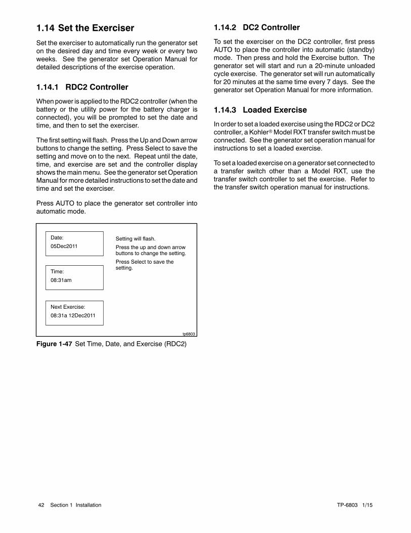
TP-6803 1/1542 Section 1 Installation
1.14 Set the Exerciser
Set the exerciser to automatically run the generator seton the desired day and time every week or every twoweeks. See the generator set Operation Manual fordetailed descriptions of the exercise operation.
1.14.1 RDC2 Controller
Whenpower is applied to theRDC2controller (when thebattery or the utility power for the battery charger isconnected), you will be prompted to set the date andtime, and then to set the exerciser.
The first settingwill flash. Press theUp andDownarrowbuttons to change the setting. Press Select to save thesetting and move on to the next. Repeat until the date,time, and exercise are set and the controller displayshows themainmenu. See the generator setOperationManual formore detailed instructions to set the date andtime and set the exerciser.
Press AUTO to place the generator set controller intoautomatic mode.
tp6803
Date:
05Dec2011
Time:
08:31am
Next Exercise:
08:31a 12Dec2011
Setting will flash.
Press the up and down arrowbuttons to change the setting.
Press Select to save thesetting.
Figure 1-47 Set Time, Date, and Exercise (RDC2)
1.14.2 DC2 Controller
To set the exerciser on the DC2 controller, first pressAUTO to place the controller into automatic (standby)mode. Then press and hold the Exercise button. Thegenerator set will start and run a 20-minute unloadedcycle exercise. The generator set will run automaticallyfor 20 minutes at the same time every 7 days. See thegenerator set Operation Manual for more information.
1.14.3 Loaded Exercise
In order to set a loaded exercise using theRDC2orDC2controller, a KohlerrModel RXT transfer switchmust beconnected. See the generator set operation manual forinstructions to set a loaded exercise.
Toset a loadedexerciseonagenerator set connected toa transfer switch other than a Model RXT, use thetransfer switch controller to set the exercise. Refer tothe transfer switch operation manual for instructions.

TP-6803 1/15 43Section 2 Drawings and Diagrams
Section 2 Drawings and Diagrams
Figure 2-1 lists the drawing numbers and page numbers.
Dimension Drawing Drawing Number Page
Dimension Drawing ADV-8424-H
Dimensions Sheet 1 44
Maintenance item locations Sheet 2 45
Maintenance item locations Sheet 3 46
Location and clearance requirements, single unit Sheet 4 47
Location and clearance requirements, parallel units Sheet 5 48
Wiring Diagrams
Schematic Diagram ADV-8706-C
1 phase, 2 pole circuit breaker Sheet 1 49
1 phase, 1 pole circuit breaker Sheet 2 50
3 phase, 3 pole circuit breaker Sheet 3 51
Wiring Diagram GM93298-C
1 phase, 2 pole circuit breaker Sheet 1 52
1 phase, 1 pole circuit breaker Sheet 2 53
3 phase, 3 pole circuit breaker Sheet 3 54
Figure 2-1 Drawings and Diagrams

TP-6803 1/1544 Section 2 Drawings and Diagrams
Figure 2-2 Dimension Drawing ADV-8424, Sheet 1 of 5

TP-6803 1/15 45Section 2 Drawings and Diagrams
Figure 2-3 Dimension Drawing ADV-8424, Sheet 2 of 5

TP-6803 1/1546 Section 2 Drawings and Diagrams
Figure 2-4 Dimension Drawing ADV-8424, Sheet 3 of 5

TP-6803 1/15 47Section 2 Drawings and Diagrams
Figure 2-5 Dimension Drawing ADV-8424, Sheet 4 of 5

TP-6803 1/1548 Section 2 Drawings and Diagrams
Figure 2-6 Dimension Drawing ADV-8424, Sheet 5 of 5

TP-6803 1/15 49Section 2 Drawings and Diagrams
-
Figure 2-7 Schematic Diagram, ADV-8706, Sheet 1 of 3

TP-6803 1/1550 Section 2 Drawings and Diagrams
-
Figure 2-8 Schematic Diagram, ADV-8706, Sheet 2 of 3
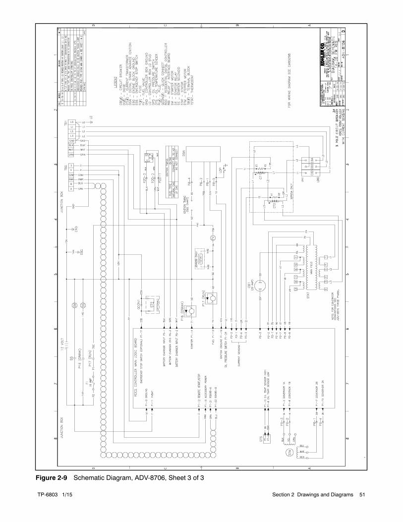
TP-6803 1/15 51Section 2 Drawings and Diagrams
-
Figure 2-9 Schematic Diagram, ADV-8706, Sheet 3 of 3

TP-6803 1/1552 Section 2 Drawings and Diagrams
-
Figure 2-10 Point-to-Point Wiring Diagram, GM93298, Sheet 1 of 3

TP-6803 1/15 53Section 2 Drawings and Diagrams
-
Figure 2-11 Point-to-Point Wiring Diagram, GM93298, Sheet 2 of 3

TP-6803 1/1554 Section 2 Drawings and Diagrams
-
Figure 2-12 Point-to-Point Wiring Diagram, GM93298, Sheet 3 of 3

TP-6803 1/15 Appendix 55
Appendix A Abbreviations
The following list contains abbreviations that may appear in this publication.
A, amp ampereABDC after bottom dead centerAC alternating currentA/D analog to digitalADC advanced digital control;
analog to digital converteradj. adjust, adjustmentADV advertising dimensional
drawingAh amp-hourAHWT anticipatory high water
temperatureAISI American Iron and Steel
InstituteALOP anticipatory low oil pressurealt. alternatorAl aluminumANSI American National Standards
Institute (formerly AmericanStandards Association, ASA)
AO anticipatory onlyAPDC Air Pollution Control DistrictAPI American Petroleum Instituteapprox. approximate, approximatelyAPU Auxiliary Power UnitAQMD Air Quality Management DistrictAR as required, as requestedAS as supplied, as stated, as
suggestedASE American Society of EngineersASME American Society of
Mechanical Engineersassy. assemblyASTM American Society for Testing
MaterialsATDC after top dead centerATS automatic transfer switchauto. automaticaux. auxiliaryavg. averageAVR automatic voltage regulatorAWG American Wire GaugeAWM appliance wiring materialbat. batteryBBDC before bottom dead centerBC battery charger, battery
chargingBCA battery charging alternatorBCI Battery Council InternationalBDC before dead centerBHP brake horsepowerblk. black (paint color), block
(engine)blk. htr. block heaterBMEP brake mean effective pressurebps bits per secondbr. brassBTDC before top dead centerBtu British thermal unitBtu/min. British thermal units per minuteC Celsius, centigradecal. calorieCAN controller area networkCARB California Air Resources BoardCAT5 Category 5 (network cable)CB circuit breakerCC crank cyclecc cubic centimeterCCA cold cranking ampsccw. counterclockwiseCEC Canadian Electrical Codecert. certificate, certification, certifiedcfh cubic feet per hour
cfm cubic feet per minuteCG center of gravityCID cubic inch displacementCL centerlinecm centimeterCMOS complementary metal oxide
substrate (semiconductor)com communications (port)coml commercialComl/Rec Commercial/Recreationalconn. connectioncont. continuedCPVC chlorinated polyvinyl chloridecrit. criticalCSA Canadian Standards
AssociationCT current transformerCu coppercUL Canadian Underwriter’s
LaboratoriesCUL Canadian Underwriter’s
Laboratoriescu. in. cubic inchcw. clockwiseCWC city water-cooledcyl. cylinderD/A digital to analogDAC digital to analog converterdB decibeldB(A) decibel (A weighted)DC direct currentDCR direct current resistancedeg., degreedept. departmentdia. diameterDI/EO dual inlet/end outletDIN Deutsches Institut fur Normung
e. V. (also Deutsche IndustrieNormenausschuss)
DIP dual inline packageDPDT double-pole, double-throwDPST double-pole, single-throwDS disconnect switchDVR digital voltage regulatorE2PROM, EEPROM
electrically-erasableprogrammable read-onlymemory
E, emer. emergency (power source)ECM electronic control module,
engine control moduleEDI electronic data interchangeEFR emergency frequency relaye.g. for example (exempli gratia)EG electronic governorEGSA Electrical Generating Systems
AssociationEIA Electronic Industries
AssociationEI/EO end inlet/end outletEMI electromagnetic interferenceemiss. emissioneng. engineEPA Environmental Protection
AgencyEPS emergency power systemER emergency relayES engineering special,
engineered specialESD electrostatic dischargeest. estimatedE-Stop emergency stopetc. et cetera (and so forth)
exh. exhaustext. externalF Fahrenheit, femaleFHM flat head machine (screw)fl. oz. fluid ounceflex. flexiblefreq. frequencyFS full scaleft. foot, feetft. lb. foot pounds (torque)ft./min. feet per minuteftp file transfer protocolg gramga. gauge (meters, wire size)gal. gallongen. generatorgenset generator setGFI ground fault interrupter
GND, groundgov. governorgph gallons per hourgpm gallons per minutegr. grade, grossGRD equipment groundgr. wt. gross weightH x W x D height by width by depthHC hex capHCHT high cylinder head temperatureHD heavy dutyHET high exhaust temp., high
engine temp.hex hexagonHg mercury (element)HH hex headHHC hex head capHP horsepowerhr. hourHS heat shrinkhsg. housingHVAC heating, ventilation, and air
conditioningHWT high water temperatureHz hertz (cycles per second)IBC International Building CodeIC integrated circuitID inside diameter, identificationIEC International Electrotechnical
CommissionIEEE Institute of Electrical and
Electronics EngineersIMS improved motor startingin. inchin. H2O inches of waterin. Hg inches of mercuryin. lb. inch poundsInc. incorporatedind. industrialint. internalint./ext. internal/externalI/O input/outputIP internet protocolISO International Organization for
StandardizationJ jouleJIS Japanese Industry Standardk kilo (1000)K kelvinkA kiloampereKB kilobyte (210 bytes)kg kilogram

TP-6803 1/1556 Appendix
kg/cm2 kilograms per squarecentimeter
kgm kilogram-meterkg/m3 kilograms per cubic meterkHz kilohertzkJ kilojoulekm kilometerkOhm, k kilo-ohmkPa kilopascalkph kilometers per hourkV kilovoltkVA kilovolt amperekVAR kilovolt ampere reactivekW kilowattkWh kilowatt-hourkWm kilowatt mechanicalkWth kilowatt-thermalL literLAN local area networkL x W x H length by width by heightlb. pound, poundslbm/ft3 pounds mass per cubic feetLCB line circuit breakerLCD liquid crystal displayLED light emitting diodeLph liters per hourLpm liters per minuteLOP low oil pressureLP liquefied petroleumLPG liquefied petroleum gasLS left sideLwa sound power level, A weightedLWL low water levelLWT low water temperaturem meter, milli (1/1000)M mega (106 when used with SI
units), malem3 cubic meterm3/hr. cubic meters per hourm3/min. cubic meters per minutemA milliampereman. manualmax. maximumMB megabyte (220 bytes)MCCB molded-case circuit breakerMCM one thousand circular milsmeggar megohmmeterMHz megahertzmi. milemil one one-thousandth of an inchmin. minimum, minutemisc. miscellaneousMJ megajoulemJ millijoulemm millimetermOhm, mmilliohmMOhm, MmegohmMOV metal oxide varistorMPa megapascalmpg miles per gallonmph miles per hourMS military standardms millisecondm/sec. meters per secondmtg. mountingMTU Motoren-und Turbinen-UnionMW megawattmW milliwattF microfaradN, norm. normal (power source)NA not available, not applicablenat. gas natural gasNBS National Bureau of Standards
NC normally closedNEC National Electrical CodeNEMA National Electrical
Manufacturers AssociationNFPA National Fire Protection
AssociationNm newton meterNO normally openno., nos. number, numbersNPS National Pipe, StraightNPSC National Pipe, Straight-couplingNPT National Standard taper pipe
thread per general useNPTF National Pipe, Taper-FineNR not required, normal relayns nanosecondOC overcrankOD outside diameterOEM original equipment
manufacturerOF overfrequencyopt. option, optionalOS oversize, overspeedOSHA Occupational Safety and Health
AdministrationOV overvoltageoz. ouncep., pp. page, pagesPC personal computerPCB printed circuit boardpF picofaradPF power factorph., phasePHC Phillipsr head Crimptiter
(screw)PHH Phillipsr hex head (screw)PHM pan head machine (screw)PLC programmable logic controlPMG permanent magnet generatorpot potentiometer, potentialppm parts per millionPROM programmable read-only
memorypsi pounds per square inchpsig pounds per square inch gaugept. pintPTC positive temperature coefficientPTO power takeoffPVC polyvinyl chlorideqt. quart, quartsqty. quantityR replacement (emergency)
power sourcerad. radiator, radiusRAM random access memoryRBUS RS-485 proprietary
communicationsRDO relay driver outputref. referencerem. remoteRes/Coml Residential/CommercialRFI radio frequency interferenceRH round headRHM round head machine (screw)rly. relayrms root mean squarernd. roundRO read onlyROM read only memoryrot. rotate, rotatingrpm revolutions per minuteRS right sideRTDs Resistance Temperature
Detectors
RTU remote terminal unitRTV room temperature vulcanizationRW read/writeSAE Society of Automotive
Engineersscfm standard cubic feet per minuteSCR silicon controlled rectifiers, sec. secondSI Systeme international d’unites,
International System of UnitsSI/EO side in/end outsil. silencerSMTP simple mail transfer protocolSN serial numberSNMP simple network management
protocolSPDT single-pole, double-throwSPST single-pole, single-throwspec specificationspecs specification(s)sq. squaresq. cm square centimetersq. in. square inchSMS short message serviceSS stainless steelstd. standardstl. steeltach. tachometerTB terminal blockTCP transmission control protocolTD time delayTDC top dead centerTDEC time delay engine cooldownTDEN time delay emergency to
normalTDES time delay engine startTDNE time delay normal to
emergencyTDOE time delay off to emergencyTDON time delay off to normaltemp. temperatureterm. terminalTHD total harmonic distortionTIF telephone influence factortol. toleranceturbo. turbochargertyp. typical (same in multiple
locations)UF underfrequencyUHF ultrahigh frequencyUIF user interfaceUL Underwriter’s Laboratories, Inc.UNC unified coarse thread (was NC)UNF unified fine thread (was NF)univ. universalURL uniform resource locator
(web address)US undersize, underspeedUV ultraviolet, undervoltageV voltVAC volts alternating currentVAR voltampere reactiveVDC volts direct currentVFD vacuum fluorescent displayVGA video graphics adapterVHF very high frequencyW wattWCR withstand and closing ratingw/ withWO write onlyw/o withoutwt. weightxfmr transformer

TP-6803 1/15 Appendix 57
Appendix B Electrical Lead Entry Template
Use the full-scale drawing in Figure 1 to mark the openings for the electrical conduit, if desired. See Section 1.9.2 formore information.
GM78090-B
SCALE: 1:1
Note: Dimensions are in mm.Two 13 mm holes are needed for 20 kW models only.
Figure 1 Template, Drilled or Punched Openings for Regulator Vent Tubes (20 kW only) and Electrical Conduit

TP-6803 1/1558 Appendix
Notes


KOHLER CO. Kohler, Wisconsin 53044Phone 920-457-4441, Fax 920-459-1646
Kohler Power SystemsAsia Pacific Headquarters7 Jurong Pier RoadSingapore 619159Phone (65) 6264-6422, Fax (65) 6264-6455
For the nearest KOHLER authorizedinstallation, service, and sales dealer inthe US and Canada:Call 1-800-544-2444 or visitKOHLERPower.comE 2011, 2012, 2013, 2014, 2015 by Kohler Co. All rights reserved.
TP-6803 1/15j