Embed Size (px)
Citation preview

Residential/Light Commercial Generator Sets
Models:
24RCL30RCL
38RCLBController:
RDC2
TP-6906 4/16c
Installation
Engine exhaust from this product contains chemicalsknown to the State of California to cause cancer, birthdefects, or other reproductive harm.
WARNINGCalifornia Proposition 65
Kohler strongly recommendsthat only factory-authorizeddistributors or dealers installand service the generator.
Product Identification Information
Generator Set Identification NumbersRecord the product identification numbers from thegenerator set nameplate(s).
Model DesignationSpecification NumberSerial Number
Accessory Number Accessory Description
Engine IdentificationRecord the product identification information from theengine nameplate.
ManufacturerModel DesignationSerial Number
Controller IdentificationRecord the controller description from the generator setoperation manual, spec sheet, or sales invoice.
Controller Description
Table of Contents
TP-6906 4/16 Table of Contents 3
Product Identification Information 2. . . . . . . . . . . . . . . . . . . . . . . . . . . . . . . . . . . . . . . . . . . . . . . . . . . . . . . . . . . . .
Safety Precautions and Instructions 5. . . . . . . . . . . . . . . . . . . . . . . . . . . . . . . . . . . . . . . . . . . . . . . . . . . . . . . . .
Introduction 9. . . . . . . . . . . . . . . . . . . . . . . . . . . . . . . . . . . . . . . . . . . . . . . . . . . . . . . . . . . . . . . . . . . . . . . . . . . . . . .
Service Assistance 10. . . . . . . . . . . . . . . . . . . . . . . . . . . . . . . . . . . . . . . . . . . . . . . . . . . . . . . . . . . . . . . . . . . . . . . . .
Section 1 Installation Instructions 11. . . . . . . . . . . . . . . . . . . . . . . . . . . . . . . . . . . . . . . . . . . . . . . . . . . . . . . . . .1.1 Introduction 11. . . . . . . . . . . . . . . . . . . . . . . . . . . . . . . . . . . . . . . . . . . . . . . . . . . . . . . . . . .1.2 Lifting Generator Set 12. . . . . . . . . . . . . . . . . . . . . . . . . . . . . . . . . . . . . . . . . . . . . . . . . . .1.3 Location and Mounting 14. . . . . . . . . . . . . . . . . . . . . . . . . . . . . . . . . . . . . . . . . . . . . . . . .
1.3.1 Location Factors 14. . . . . . . . . . . . . . . . . . . . . . . . . . . . . . . . . . . . . . . . . . . . . . .1.3.2 Mounting Surface 14. . . . . . . . . . . . . . . . . . . . . . . . . . . . . . . . . . . . . . . . . . . . . .1.3.3 Vibration Isolation 14. . . . . . . . . . . . . . . . . . . . . . . . . . . . . . . . . . . . . . . . . . . . . .1.3.4 Prepare Site 15. . . . . . . . . . . . . . . . . . . . . . . . . . . . . . . . . . . . . . . . . . . . . . . . . .1.3.5 Mount the Generator Set 15. . . . . . . . . . . . . . . . . . . . . . . . . . . . . . . . . . . . . . .
1.4 Electrical System 16. . . . . . . . . . . . . . . . . . . . . . . . . . . . . . . . . . . . . . . . . . . . . . . . . . . . . .1.4.1 Electrical Connections 17. . . . . . . . . . . . . . . . . . . . . . . . . . . . . . . . . . . . . . . . . .1.4.2 Terminal Connector Torque 18. . . . . . . . . . . . . . . . . . . . . . . . . . . . . . . . . . . . .1.4.3 Ground and Neutral Connections 19. . . . . . . . . . . . . . . . . . . . . . . . . . . . . . . .1.4.4 Battery Chargers 19. . . . . . . . . . . . . . . . . . . . . . . . . . . . . . . . . . . . . . . . . . . . . .1.4.5 Power Supply 19. . . . . . . . . . . . . . . . . . . . . . . . . . . . . . . . . . . . . . . . . . . . . . . . .1.4.6 Connect AC and DC Wiring 20. . . . . . . . . . . . . . . . . . . . . . . . . . . . . . . . . . . . .1.4.7 Automatic Transfer Switch Connection 22. . . . . . . . . . . . . . . . . . . . . . . . . . . .1.4.8 Communication Cable Specifications 25. . . . . . . . . . . . . . . . . . . . . . . . . . . . .1.4.9 System Connections with Accessory Modules 26. . . . . . . . . . . . . . . . . . . . .1.4.10 Other Accessories 28. . . . . . . . . . . . . . . . . . . . . . . . . . . . . . . . . . . . . . . . . . . . .
1.5 Engine Starting Battery 29. . . . . . . . . . . . . . . . . . . . . . . . . . . . . . . . . . . . . . . . . . . . . . . . .1.6 Fuel System 30. . . . . . . . . . . . . . . . . . . . . . . . . . . . . . . . . . . . . . . . . . . . . . . . . . . . . . . . . .
1.6.1 Fuel Lines 31. . . . . . . . . . . . . . . . . . . . . . . . . . . . . . . . . . . . . . . . . . . . . . . . . . . .1.6.2 Gas Regulators 32. . . . . . . . . . . . . . . . . . . . . . . . . . . . . . . . . . . . . . . . . . . . . . . .1.6.3 Install and Connect Fuel Supply 32. . . . . . . . . . . . . . . . . . . . . . . . . . . . . . . . .1.6.4 Fuel Conversion Procedures 33. . . . . . . . . . . . . . . . . . . . . . . . . . . . . . . . . . . .
1.7 Cooling System 34. . . . . . . . . . . . . . . . . . . . . . . . . . . . . . . . . . . . . . . . . . . . . . . . . . . . . . .1.8 Prestart Installation Check 35. . . . . . . . . . . . . . . . . . . . . . . . . . . . . . . . . . . . . . . . . . . . . .1.9 Set Exerciser 36. . . . . . . . . . . . . . . . . . . . . . . . . . . . . . . . . . . . . . . . . . . . . . . . . . . . . . . . . .1.10 Operation Tests 36. . . . . . . . . . . . . . . . . . . . . . . . . . . . . . . . . . . . . . . . . . . . . . . . . . . . . . .1.11 OnCue Plus Generator Management System 37. . . . . . . . . . . . . . . . . . . . . . . . . . . . . .
Section 2 Accessories 39. . . . . . . . . . . . . . . . . . . . . . . . . . . . . . . . . . . . . . . . . . . . . . . . . . . . . . . . . . . . . . . . . . . . .2.1 Introduction 39. . . . . . . . . . . . . . . . . . . . . . . . . . . . . . . . . . . . . . . . . . . . . . . . . . . . . . . . . . .2.2 Engine Heaters 39. . . . . . . . . . . . . . . . . . . . . . . . . . . . . . . . . . . . . . . . . . . . . . . . . . . . . . . .
2.2.1 Oil Pan Heaters 39. . . . . . . . . . . . . . . . . . . . . . . . . . . . . . . . . . . . . . . . . . . . . . .2.2.2 Block Heaters 39. . . . . . . . . . . . . . . . . . . . . . . . . . . . . . . . . . . . . . . . . . . . . . . . .
2.3 Programmable Interface Module (PIM) 41. . . . . . . . . . . . . . . . . . . . . . . . . . . . . . . . . . .2.3.1 PIM to Generator Set Connections 41. . . . . . . . . . . . . . . . . . . . . . . . . . . . . . .2.3.2 PIM Inputs and Outputs 41. . . . . . . . . . . . . . . . . . . . . . . . . . . . . . . . . . . . . . . .
2.4 Load Management 42. . . . . . . . . . . . . . . . . . . . . . . . . . . . . . . . . . . . . . . . . . . . . . . . . . . . .2.4.1 Power Relay Module 42. . . . . . . . . . . . . . . . . . . . . . . . . . . . . . . . . . . . . . . . . . .
Table of Contents, continued
TP-6906 4/16Table of Contents4
Section 3 Generator Reconnection 43. . . . . . . . . . . . . . . . . . . . . . . . . . . . . . . . . . . . . . . . . . . . . . . . . . . . . . . . . .3.1 Voltage Reconnection 43. . . . . . . . . . . . . . . . . . . . . . . . . . . . . . . . . . . . . . . . . . . . . . . . . .3.2 Four-Lead (Single-Phase) Generator Sets 44. . . . . . . . . . . . . . . . . . . . . . . . . . . . . . . .3.3 12-Lead (Three-Phase) Generator Sets 44. . . . . . . . . . . . . . . . . . . . . . . . . . . . . . . . . . .3.4 Changing System Settings 46. . . . . . . . . . . . . . . . . . . . . . . . . . . . . . . . . . . . . . . . . . . . . .3.5 Voltage Calibration 49. . . . . . . . . . . . . . . . . . . . . . . . . . . . . . . . . . . . . . . . . . . . . . . . . . . . .
3.5.1 Calibration using the RDC2 Controller Keypad and Menus 49. . . . . . . . . .3.5.2 Calibration Using SiteTech 51. . . . . . . . . . . . . . . . . . . . . . . . . . . . . . . . . . . . . .
Section 4 Diagrams and Drawings 53. . . . . . . . . . . . . . . . . . . . . . . . . . . . . . . . . . . . . . . . . . . . . . . . . . . . . . . . . .
Appendix A Abbreviations 67. . . . . . . . . . . . . . . . . . . . . . . . . . . . . . . . . . . . . . . . . . . . . . . . . . . . . . . . . . . . . . . .

TP-6906 4/16 5Safety Precautions and Instructions
Safety Precautions and Instructions
IMPORTANTSAFETY INSTRUCTIONS.Electromechanical equipment,including generator sets, transferswitches, switchgear, and accessories,can cause bodily harm and poselife-threatening danger whenimproperly installed, operated, ormaintained. To prevent accidents beaware of potential dangers and actsafely. Read and follow all safetyprecautions and instructions. SAVETHESE INSTRUCTIONS.
Thismanual has several types of safetyprecautions and instructions: Danger,Warning, Caution, and Notice.
DANGER
Danger indicates the presence of ahazard that will cause severepersonal injury, death, orsubstantialproperty damage.
WARNING
Warning indicates the presence of ahazard that can cause severepersonal injury, death, orsubstantialproperty damage.
CAUTION
Caution indicates the presence of ahazard that will or can cause minorpersonal injury or property damage.
NOTICENotice communicates installation,operation, or maintenance informationthat is safety related but not hazardrelated.
Safety decals affixed to the equipmentin prominent places alert the operatoror service technician to potentialhazards and explain how to act safely.The decals are shown throughout thispublication to improve operatorrecognition. Replace missing ordamaged decals.
Accidental Starting
Accidental starting.Can cause severe injury or death.
Disconnect the battery cables beforeworking on the generator set.Remove the negative (--) lead firstwhen disconnecting the battery.Reconnect the negative (--) lead lastwhen reconnecting the battery.
WARNING
Disabling the generator set.Accidental starting can causesevere injury or death. Beforeworking on the generator set orequipment connected to the set,disable the generator set as follows:(1) Press the generator set off/resetbutton to shut down the generator set.(2) Disconnect the power to the batterycharger, if equipped. (3) Remove thebattery cables, negative (--) lead first.Reconnect the negative (--) lead lastwhen reconnecting the battery. Followthese precautions to prevent thestarting of the generator set by theremote start/stop switch.
Battery
Sulfuric acid in batteries.Can cause severe injury or death.
Wear protective goggles andclothing. Battery acid may causeblindness and burn skin.
WARNING
Explosion.Can cause severe injury or death.Relays in the battery chargercause arcs or sparks.
Locate the battery in a well-ventilatedarea. Isolate the battery charger fromexplosive fumes.
WARNING
Battery electrolyte is a dilutedsulfuric acid. Battery acid cancausesevere injury or death. Battery acidcan cause blindness and burn skin.Always wear splashproof safetygoggles, rubber gloves, and bootswhen servicing the battery. Do notopen a sealed battery or mutilate thebattery case. If battery acid splashes inthe eyes or on the skin, immediatelyflush the affected area for 15 minuteswith large quantities of clean water.Seek immediatemedical aid in the caseof eye contact. Never add acid to abattery after placing the battery inservice, as thismay result in hazardousspattering of battery acid.
Battery acid cleanup. Battery acidcan cause severe injury or death.Battery acid is electrically conductiveand corrosive. Add 500 g (1 lb.) ofbicarbonate of soda (baking soda) to acontainer with 4 L (1 gal.) of water andmix the neutralizing solution. Pour theneutralizing solution on the spilledbattery acid and continue to add theneutralizing solution to the spilledbattery acid until all evidence of achemical reaction (foaming) hasceased. Flush the resulting liquid withwater and dry the area.
Battery gases. Explosion can causesevere injury or death. Battery gasescan cause an explosion. Do not smokeor permit flames or sparks to occur neara battery at any time, particularly whenit is charging. Do not dispose of abattery in a fire. To prevent burns andsparks that could cause an explosion,avoid touching the battery terminalswith tools or other metal objects.Remove all jewelry before servicing theequipment. Discharge static electricityfrom your body before touchingbatteries by first touching a grounded
TP-6906 4/166 Safety Precautions and Instructions
metal surface away from thebattery. Toavoid sparks, do not disturb the batterycharger connections while the batteryis charging. Always turn the batterycharger off before disconnecting thebattery connections. Ventilate thecompartments containing batteries toprevent accumulation of explosivegases.
Battery short circuits. Explosioncan cause severe injury or death.Short circuits can cause bodily injuryand/or equipment damage.Disconnect the battery beforegenerator set installation ormaintenance. Remove all jewelrybefore servicing the equipment. Usetools with insulated handles. Removethe negative (--) lead first whendisconnecting the battery. Reconnectthe negative (--) lead last whenreconnecting the battery. Neverconnect the negative (--) battery cableto the positive (+) connection terminalof the starter solenoid. Do not test thebattery condition by shorting theterminals together.
Engine Backfire/FlashFire
Risk of fire.Can cause severe injury or death.
Do not smoke or permit flames orsparks near fuels or the fuel system.
WARNING
Servicing the fuel system. A flashfire cancausesevere injuryordeath.Do not smoke or permit flames orsparks near the carburetor, fuel line,fuel filter, fuel pump, or other potentialsources of spilled fuels or fuel vapors.Catch fuels in an approved containerwhen removing the fuel line orcarburetor.
Servicing the air cleaner. A suddenbackfire can cause severe injury ordeath. Do not operate the generatorset with the air cleaner removed.
Combustible materials. A fire cancause severe injury or death.Generator set engine fuels and fuelvapors are flammable and explosive.Handle these materials carefully to
minimize the risk of fire or explosion.Equip the compartment or nearby areawith a fully charged fire extinguisher.Select a fire extinguisher rated ABC orBC for electrical fires or asrecommended by the local fire code oran authorized agency. Train allpersonnel on fire extinguisheroperation and fire preventionprocedures.
Exhaust System
Carbon monoxide.Can cause severe nausea,fainting, or death.
The exhaust system must beleakproof and routinely inspected.
WARNING
Generator set operation. Carbonmonoxide can cause severe nausea,fainting, or death. Carbon monoxideis an odorless, colorless, tasteless,nonirritating gas that can cause death ifinhaled for even a short time. Avoidbreathing exhaust fumeswhenworkingon or near the generator set. Neveroperate the generator set inside abuilding. Never operate the generatorset where exhaust gas could seepinside or be drawn into a potentiallyoccupied building through windows, airintake vents, or other openings.
Carbon monoxide symptoms.Carbon monoxide can cause severenausea, fainting, or death. Carbonmonoxide is a poisonous gas present inexhaust gases. Carbonmonoxide is anodorless, colorless, tasteless,nonirritating gas that can cause death ifinhaled for even a short time. Carbonmonoxide poisoning symptoms includebut are not limited to the following:D Light-headedness, dizzinessD Physical fatigue, weakness injoints and muscles
D Sleepiness, mental fatigue,inability to concentrateor speak clearly, blurred vision
D Stomachache, vomiting, nauseaIf experiencing any of these symptomsand carbon monoxide poisoning ispossible, seek fresh air immediatelyand remain active. Do not sit, lie down,or fall asleep. Alert others to the
possibility of carbon monoxidepoisoning. Seek medical attention ifthe condition of affected persons doesnot improvewithinminutes of breathingfresh air.
Carbon monoxide detectors.Carbon monoxide can cause severenausea, fainting, or death. Installcarbon monoxide detectors on eachlevel of any building adjacent to thegenerator set. Locate the detectors toadequately warn the building’soccupants of the presence of carbonmonoxide. Keep the detectorsoperational at all times. Periodicallytest and replace the carbon monoxidedetectors according to themanufacturer’s instructions.
Fuel System
Explosive fuel vapors.Can cause severe injury or death.
Use extreme care when handling,storing, and using fuels.
WARNING
The fuel system. Explosive fuelvapors can cause severe injury ordeath. Vaporized fuels are highlyexplosive. Use extreme care whenhandling and storing fuels. Store fuelsin a well-ventilated area away fromspark-producing equipment and out ofthe reach of children. Never add fuel tothe tank while the engine is runningbecause spilled fuel may ignite oncontact with hot parts or from sparks.Do not smoke or permit flames orsparks to occur near sources of spilledfuel or fuel vapors. Keep the fuel linesand connections tight and in goodcondition. Do not replace flexible fuellines with rigid lines. Use flexiblesections to avoid fuel line breakagecausedby vibration. Donot operate thegenerator set in the presence of fuelleaks, fuel accumulation, or sparks.Repair fuel systems before resuminggenerator set operation.
Explosive fuel vapors can causesevere injury or death. Takeadditional precautions when using thefollowing fuels:
TP-6906 4/16 7Safety Precautions and Instructions
Propane (LPG)—Adequate ventilationis mandatory. Because propane isheavier than air, install propane gasdetectors low in a room. Inspect thedetectors per the manufacturer’sinstructions.
Natural Gas—Adequate ventilation ismandatory. Because natural gas rises,install natural gas detectors high in aroom. Inspect the detectors per themanufacturer’s instructions.
Gas fuel leaks. Explosive fuelvapors can cause severe injury ordeath. Fuel leakage can cause anexplosion. Check the LPG vapor ornatural gas fuel system for leakage byusinga soapandwater solutionwith thefuel system test pressurized to6--8 ounces per square inch(10--14 inches water column). Do notuse a soap solution containing eitherammonia or chlorine because bothprevent bubble formation. A successfultest depends on the ability of thesolution to bubble.
Hazardous Noise
Hazardous noise.Can cause hearing loss.
Never operate the generator setwithout a muffler or with a faultyexhaust system.
CAUTION
Engine noise. Hazardous noise cancause hearing loss. Generator setsnot equipped with sound enclosurescan produce noise levels greater than105 dBA. Prolonged exposure to noiselevels greater than 85 dBA can causepermanent hearing loss. Wear hearingprotection when near an operatinggenerator set.
Hazardous Voltage/Moving Parts
Hazardous voltage.Will cause severe injury or death.
Disconnect all power sources beforeopening the enclosure.
DANGER
Hazardous voltage.Can cause severe injury or death.
Operate the generator set only whenall guards and electrical enclosuresare in place.
Moving parts.
WARNING
Hazardous voltage.Backfeed to the utility system cancause property damage, severeinjury, or death.
If the generator set is used forstandby power, install an automatictransfer switch to prevent inadvertentinterconnection of standby andnormal sources of supply.
WARNING
Hazardous voltage.Will cause severe injury or death.
This equipment must be installed andserviced by qualified electricalpersonnel.
DANGER
Welding the generator set.Can cause severe electricalequipment damage.
Never weld components of thegenerator set without firstdisconnecting the battery, controllerwiring harness, and engine electroniccontrol module (ECM).
CAUTION
Airborne particles.Can cause severe injury or blind-ness.
Wear protective goggles and clothingwhen using power tools, hand tools,or compressed air.
WARNING
Grounding electrical equipment.Hazardous voltage can causesevere injury or death. Electrocutionis possible whenever electricity ispresent. Ensure you comply with allapplicable codes and standards.Electrically ground the generator set,transfer switch, and related equipmentand electrical circuits. Turn off themaincircuit breakers of all power sourcesbefore servicing the equipment. Nevercontact electrical leads or applianceswhen standing in water or on wetground because these conditionsincrease the risk of electrocution.
Disconnecting the electrical load.Hazardous voltage can causesevere injury or death. Disconnectthe generator set from the load byturning off the line circuit breaker or bydisconnecting the generator set outputleads from the transfer switch andheavily taping the ends of the leads.High voltage transferred to the loadduring testing may cause personalinjury and equipment damage. Do notuse the safeguard circuit breaker inplace of the line circuit breaker. Thesafeguard circuit breaker does notdisconnect the generator set from theload.
TP-6906 4/168 Safety Precautions and Instructions
Welding on the generator set. Cancause severe electrical equipmentdamage. Before welding on thegenerator set perform the followingsteps: (1) Remove the battery cables,negative (--) lead first. (2) Disconnectall engine electronic control module(ECM) connectors. (3) Disconnect allgenerator set controller and voltageregulator circuit board connectors.(4) Disconnect the engine battery-charging alternator connections.(5) Attach the weld ground connectionclose to the weld location.
Connecting the battery and thebattery charger. Hazardous voltagecan cause severe injury or death.Reconnect the battery correctly,positive to positive and negative tonegative, to avoid electrical shock anddamage to the battery charger andbattery(ies). Have a qualifiedelectrician install the battery(ies).
Short circuits. Hazardousvoltage/current can cause severeinjury or death. Short circuits cancause bodily injury and/or equipmentdamage. Do not contact electricalconnections with tools or jewelry whilemaking adjustments or repairs.Remove all jewelry before servicing theequipment.
Engine block heater. Hazardousvoltage can cause severe injury ordeath. The engine block heater cancause electrical shock. Remove theengine block heater plug from theelectrical outlet before working on theblock heater electrical connections.
Engine oil pan heater. Hazardousvoltage can cause severe injury ordeath. The engine oil pan heater cancause electrical shock. Disconnectpower to the engine oil pan heater andallow to cool before working on the oilpan heater electrical connections.
Electrical backfeed to the utility.Hazardous backfeed voltage cancause severe injury or death. Installa transfer switch in standby powerinstallations to prevent the connectionof standby and other sources of power.Electrical backfeed into a utilityelectrical system can cause severeinjury or death to utility personnelworking on power lines.
Servicing the generator set when itis operating. Exposedmoving partscan cause severe injury or death.Keep hands, feet, hair, clothing, andtest leads away from the belts andpulleys when the generator set isrunning. Replace guards, screens, andcovers before operating the generatorset.
Hot Parts
Hot coolant and steam.Can cause severe injury or death.
Before removing the pressure cap,stop the generator set and allow it tocool. Then loosen the pressure capto relieve pressure.
WARNING
Hot engine and exhaust system.Can cause severe injury or death.
Do not work on the generator set untilit cools.
WARNING
Servicing the alternator. Hot partscan cause severe injury or death.Avoid touching the alternator field orexciter armature. When shorted, thealternator field and exciter armaturebecome hot enough to cause severeburns.
Servicing the exhaust system. Hotparts can cause severe injury ordeath. Do not touch hot engine parts.The engine and exhaust systemcomponents become extremely hotduring operation.
Servicing the engine heater. Hotparts can cause minor personalinjury or property damage. Install theheater before connecting it to power.Operating the heater before installationcan cause burns and componentdamage. Disconnect power to theheater and allow it to cool beforeservicing the heater or nearby parts.
Servicing the engine oil pan heater.Heated components can causesevere injury. The oil pan heater willrapidly become hot when energized.Donot touch theoil panheaterwhile it ishot. Disconnect power to the engine oilpan heater and allow to cool beforeservicing it or nearby parts.
NoticeNOTICE
Canadian installations only. Forstandby service connect the output ofthe generator set to a suitably ratedtransfer switch in accordance withCanadian Electrical Code, Part 1.
NOTICEElectrostatic discharge damage.Electrostatic discharge (ESD)damages electronic circuit boards.Prevent electrostatic dischargedamage by wearing an approvedgrounding wrist strap when handlingelectronic circuit boards or integratedcircuits. An approved grounding wriststrap provides a high resistance (about1 megohm), not a direct short, toground.
TP-6906 4/16 9Introduction
Introduction
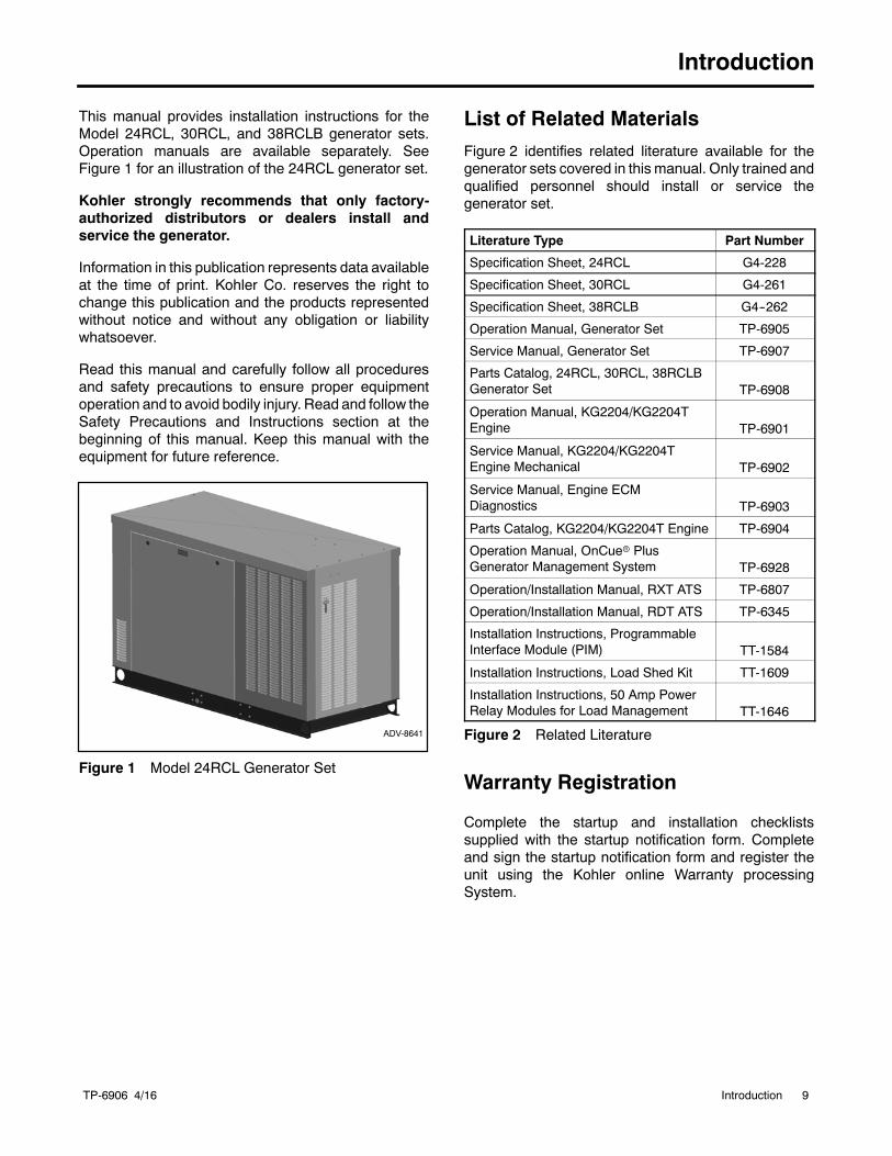
This manual provides installation instructions for theModel 24RCL, 30RCL, and 38RCLB generator sets.Operation manuals are available separately. SeeFigure 1 for an illustration of the 24RCL generator set.
Kohler strongly recommends that only factory-authorized distributors or dealers install andservice the generator.
Information in this publication represents data availableat the time of print. Kohler Co. reserves the right tochange this publication and the products representedwithout notice and without any obligation or liabilitywhatsoever.
Read this manual and carefully follow all proceduresand safety precautions to ensure proper equipmentoperation and to avoid bodily injury. Read and follow theSafety Precautions and Instructions section at thebeginning of this manual. Keep this manual with theequipment for future reference.
ADV-8641
Figure 1 Model 24RCL Generator Set
List of Related MaterialsFigure 2 identifies related literature available for thegenerator sets covered in this manual. Only trained andqualified personnel should install or service thegenerator set.
Literature Type Part Number
Specification Sheet, 24RCL G4-228
Specification Sheet, 30RCL G4-261
Specification Sheet, 38RCLB G4--262
Operation Manual, Generator Set TP-6905
Service Manual, Generator Set TP-6907
Parts Catalog, 24RCL, 30RCL, 38RCLBGenerator Set TP-6908
Operation Manual, KG2204/KG2204TEngine TP-6901
Service Manual, KG2204/KG2204TEngine Mechanical TP-6902
Service Manual, Engine ECMDiagnostics TP-6903
Parts Catalog, KG2204/KG2204T Engine TP-6904
Operation Manual, OnCuer PlusGenerator Management System TP-6928
Operation/Installation Manual, RXT ATS TP-6807
Operation/Installation Manual, RDT ATS TP-6345
Installation Instructions, ProgrammableInterface Module (PIM) TT-1584
Installation Instructions, Load Shed Kit TT-1609
Installation Instructions, 50 Amp PowerRelay Modules for Load Management TT-1646
Figure 2 Related Literature
Warranty Registration
Complete the startup and installation checklistssupplied with the startup notification form. Completeand sign the startup notification form and register theunit using the Kohler online Warranty processingSystem.
TP-6906 4/1610 Service Assistance
Service Assistance
For professional advice on generator powerrequirements and conscientious service, pleasecontact your nearest authorized Kohlerdistributor/dealer.
D Consult the Yellow Pages under the headingGenerators—Electric.
D Visit the Kohler Power Systems website atKOHLERPower.com.
D Look at the labels and decals on your Kohler productor review the appropriate literature or documentsincluded with the product.
D Call toll free in the US and Canada 1-800-544-2444.
D Outside theUSandCanada, call the nearest regionaloffice.
Headquarters Europe, Middle East, Africa(EMEA)Kohler Power Systems Netherlands B.V.Kristallaan 14761 ZC ZevenbergenThe NetherlandsPhone: (31) 168 331630Fax: (31) 168 331631
Asia PacificPower Systems Asia Pacific Regional OfficeSingapore, Republic of SingaporePhone: (65) 6264-6422Fax: (65) 6264-6455
ChinaNorth China Regional Office, BeijingPhone: (86) 10 6518 7950
(86) 10 6518 7951(86) 10 6518 7952
Fax: (86) 10 6518 7955
East China Regional Office, ShanghaiPhone: (86) 21 6288 0500Fax: (86) 21 6288 0550
India, Bangladesh, Sri LankaIndia Regional OfficeBangalore, IndiaPhone: (91) 80 3366208
(91) 80 3366231Fax: (91) 80 3315972
Japan, KoreaNorth Asia Regional OfficeTokyo, JapanPhone: (813) 3440-4515Fax: (813) 3440-2727
Latin AmericaLatin America Regional OfficeLakeland, Florida, USAPhone: (863) 619-7568Fax: (863) 701-7131
TP-6906 4/16 11Section 1 Installation Instructions
Section 1 Installation Instructions
1.1 IntroductionReview this entire section and the Safety Precautionsbefore starting the installation procedure. Thegenerator set specification sheet also contains data thatmay be required during the installation process.
The generator set and accessories must be installed byan authorized Kohler distributor/dealer or authorizedrepresentative. The installation must comply with theNational Electrical Code (NEC), state, and local codes.For Canadian installations, refer to the CanadianElectrical Code (CEC).
Note: These instructions outline one procedure forinstalling the generator set. Local codes mayrequire different procedures.
The generator set must be installed outdoors. Theexhaust systems on enclosed units are designed foroutdoor installation only.
Note: DO NOT install these generator sets inside abuilding.
Note: Install carbon monoxide (CO) detector(s) oneach level of any building adjacent to a generatorset. Locate the detectors to adequately warn thebuilding’s occupants of the presence of carbonmonoxide.
Read and follow the safety precautions in this manualand observe the decals on the equipment. Refer to thediagrams and drawings in Section 4 for dimensions andelectrical connections during the installation procedure.Read the entire installation procedure and obtain theaccessories and tools needed before beginninginstallation. Perform the steps in the order shown.
To install optional accessories, follow the instructionsprovided with each kit.
Hazardous voltage.Backfeed to the utility system cancause property damage, severeinjury, or death.
If the generator set is used forstandby power, install an automatictransfer switch to prevent inadvertentinterconnection of standby andnormal sources of supply.
WARNING
Grounding electrical equipment. Hazardous voltage cancause severe injury or death. Electrocution is possiblewhenever electricity is present. Ensure you comply with allapplicable codes and standards. Electrically ground thegenerator set, transfer switch, and related equipment andelectrical circuits. Turn off the main circuit breakers of allpower sources before servicing the equipment. Never contactelectrical leads or applianceswhen standing inwater or onwetground because these conditions increase the risk ofelectrocution.
Carbon monoxide.Can cause severe nausea,fainting, or death.
The exhaust system must beleakproof and routinely inspected.
WARNING
Generator set operation. Carbon monoxide can causesevere nausea, fainting, or death. Carbon monoxide is anodorless, colorless, tasteless, nonirritating gas that can causedeath if inhaled for even a short time. Avoid breathing exhaustfumes when working on or near the generator set. Neveroperate the generator set inside a building. Never operate thegenerator set where exhaust gas could seep inside or bedrawn into a potentially occupied building throughwindows, airintake vents, or other openings.
Carbon monoxide detectors. Carbon monoxide cancause severe nausea, fainting, or death. Install carbonmonoxide detectors on each level of any building adjacent tothe generator set. Locate the detectors to adequatelywarn thebuilding’s occupants of the presence of carbon monoxide.Keep the detectors operational at all times. Periodically testand replace the carbon monoxide detectors according to themanufacturer’s instructions.
TP-6906 4/1612 Section 1 Installation Instructions
Tools Required:D Multimeter (for measuring voltage and current)D Frequency meter (may be part of multimeter)D Pressure gauge or manometer (for measuring fuelpressure)
D Torque wrenchD WrenchesD ScrewdriversD Socket wrenches or nut driversD PliersD Safety glasses or gogglesD Drill with bits and hole saw
Installer/Customer-Supplied Items:D One BCI group 24 size 12-volt battery with aminimum rating of 630 cold cranking amps (CCA) at0_F
D Gravel or crushed stoneD Concrete mounting padD Cables and conduitD Fuel supply line with shutoff valve and pipe sealant(provided by fuel supplier)
D Carbon monoxide (CO) detector(s)
Available Accessories:D BatteryD Battery heaterD Block heaterD Oil pan heaterD Flexible fuel linesD Load management systemD Programmable Interface Module (PIM)See TT-1584 for installation instructions.
1.2 Lifting Generator Set
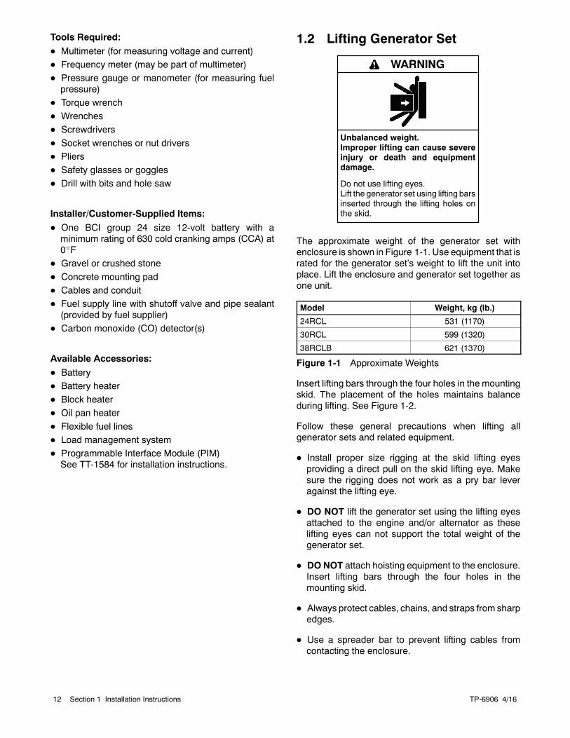
Unbalanced weight.Improper lifting can cause severeinjury or death and equipmentdamage.
Do not use lifting eyes.Lift the generator set using lifting barsinserted through the lifting holes onthe skid.
WARNING
The approximate weight of the generator set withenclosure is shown in Figure 1-1. Use equipment that israted for the generator set’s weight to lift the unit intoplace. Lift the enclosure and generator set together asone unit.
Model Weight, kg (lb.)
24RCL 531 (1170)
30RCL 599 (1320)
38RCLB 621 (1370)
Figure 1-1 Approximate Weights
Insert lifting bars through the four holes in the mountingskid. The placement of the holes maintains balanceduring lifting. See Figure 1-2.
Follow these general precautions when lifting allgenerator sets and related equipment.
D Install proper size rigging at the skid lifting eyesproviding a direct pull on the skid lifting eye. Makesure the rigging does not work as a pry bar leveragainst the lifting eye.
D DO NOT lift the generator set using the lifting eyesattached to the engine and/or alternator as theselifting eyes can not support the total weight of thegenerator set.
D DONOT attach hoisting equipment to the enclosure.Insert lifting bars through the four holes in themounting skid.
D Always protect cables, chains, and straps from sharpedges.
D Use a spreader bar to prevent lifting cables fromcontacting the enclosure.
TP-6906 4/16 13Section 1 Installation Instructions
D Lifting should only be conducted by those trained andexperienced in lifting and rigging to achieve a safeand effective lift. Consideration needs to be given to,but not necessarily limited to the following items:
d Weight and center of gravity of the equipmentbeing lifted
d Weight and center of gravity of the lifting device
d Boom angles
d Selection of rated rigging
d Stability of lifting foundation
d Wind and weather conditions
d Local or regional codes that may require or restricttypes of rigging.
The distributor/lifting contractor should choose one ofthe followingmethods to lift the generator set dependingupon the location circumstancesand the generator set’sweight and size.
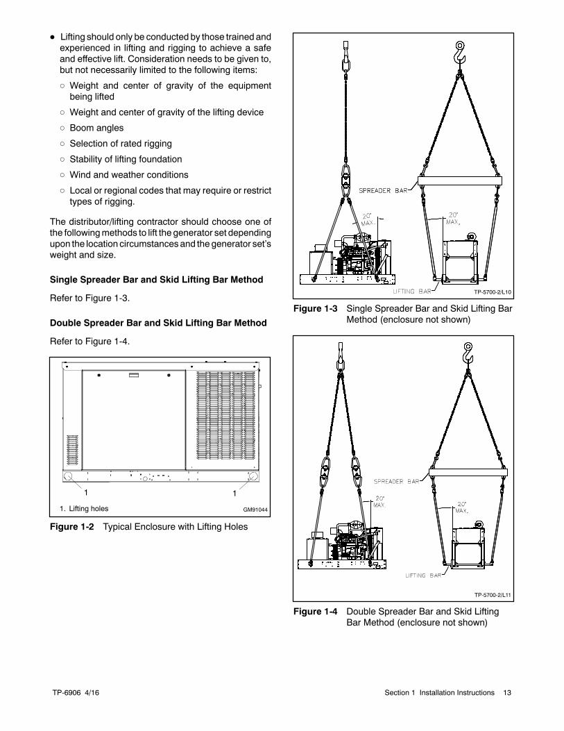
Single Spreader Bar and Skid Lifting Bar Method
Refer to Figure 1-3.
Double Spreader Bar and Skid Lifting Bar Method
Refer to Figure 1-4.
1. Lifting holes
1
GM91044
1
Figure 1-2 Typical Enclosure with Lifting Holes
TP-5700-2/L10
Figure 1-3 Single Spreader Bar and Skid Lifting BarMethod (enclosure not shown)
TP-5700-2/L11
Figure 1-4 Double Spreader Bar and Skid LiftingBar Method (enclosure not shown)
TP-6906 4/1614 Section 1 Installation Instructions
1.3 Location and Mounting
1.3.1 Location Factors
The manufacturer recommends mounting thegenerator set on concrete at ground level. Forinstallations suspended above ground level, includingroof installations, weight considerations are especiallyimportant. The building engineer must determinewhether the structure can support the weight of thegenerator set.
The location of the generator set must:
D Support the weight of the generator set and relatedequipment suchas batteries, radiators, andmountingpad(s). Keep in mind that the mounting pad weightmay exceed the weight of the generator set.
D Meet applicable fire rating and other national, state,and local codes and standards.
D Minimize the risk that people will come into contactwith hot generator set surfaces.
D Position the generator set over a noncombustiblesurface. DO NOT allow accumulation of combustiblematerials under or around the generator set.
D Permit vibration isolation to reducenoise andpreventdamage.
D Not be subject to flooding.
D Allow safe expulsion of exhaust.
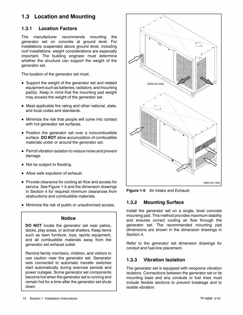
D Provide clearance for cooling air flow and access forservice. See Figure 1-5 and the dimension drawingsin Section 4 for required minimum clearances fromobstructions and combustible materials.
D Minimize the risk of public or unauthorized access.
NoticeDO NOT locate the generator set near patios,decks, play areas, or animal shelters. Keep itemssuch as lawn furniture, toys, sports equipment,and all combustible materials away from thegenerator set exhaust outlet.
Remind family members, children, and visitors touse caution near the generator set. Generatorsets connected to automatic transfer switchesstart automatically during exercise periods andpower outages. Some generator set componentsbecome hot when the generator set is running andremain hot for a time after the generator set shutsdown.
SERVICE SIDE
GM91044--MA2
Figure 1-5 Air Intake and Exhaust
1.3.2 Mounting Surface
Install the generator set on a single, level concretemounting pad. This method provides maximum stabilityand ensures correct cooling air flow through thegenerator set. The recommended mounting paddimensions are shown in the dimension drawings inSection 4.
Refer to the generator set dimension drawings forconduit and fuel-line placement.
1.3.3 Vibration Isolation
The generator set is equipped with neoprene vibrationisolators. Connections between the generator set or itsmounting base and any conduits or fuel lines mustinclude flexible sections to prevent breakage and toisolate vibration.
TP-6906 4/16 15Section 1 Installation Instructions
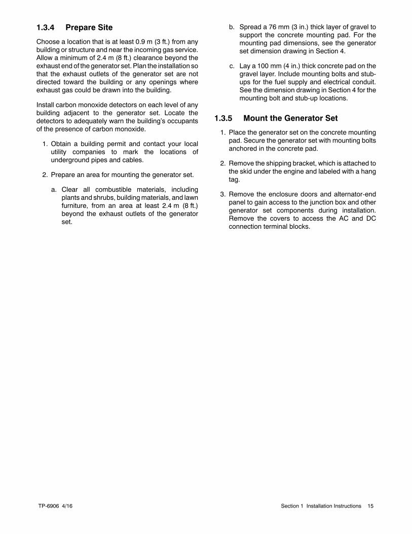
1.3.4 Prepare Site
Choose a location that is at least 0.9 m (3 ft.) from anybuilding or structure and near the incoming gas service.Allow a minimum of 2.4 m (8 ft.) clearance beyond theexhaust end of the generator set. Plan the installation sothat the exhaust outlets of the generator set are notdirected toward the building or any openings whereexhaust gas could be drawn into the building.
Install carbon monoxide detectors on each level of anybuilding adjacent to the generator set. Locate thedetectors to adequately warn the building’s occupantsof the presence of carbon monoxide.
1. Obtain a building permit and contact your localutility companies to mark the locations ofunderground pipes and cables.
2. Prepare an area for mounting the generator set.
a. Clear all combustible materials, includingplants and shrubs, buildingmaterials, and lawnfurniture, from an area at least 2.4 m (8 ft.)beyond the exhaust outlets of the generatorset.
b. Spread a 76 mm (3 in.) thick layer of gravel tosupport the concrete mounting pad. For themounting pad dimensions, see the generatorset dimension drawing in Section 4.
c. Lay a 100 mm (4 in.) thick concrete pad on thegravel layer. Include mounting bolts and stub-ups for the fuel supply and electrical conduit.See the dimension drawing in Section 4 for themounting bolt and stub-up locations.
1.3.5 Mount the Generator Set
1. Place the generator set on the concrete mountingpad. Secure the generator set with mounting boltsanchored in the concrete pad.
2. Remove the shipping bracket, which is attached tothe skid under the engine and labeled with a hangtag.
3. Remove the enclosure doors and alternator-endpanel to gain access to the junction box and othergenerator set components during installation.Remove the covers to access the AC and DCconnection terminal blocks.
TP-6906 4/1616 Section 1 Installation Instructions
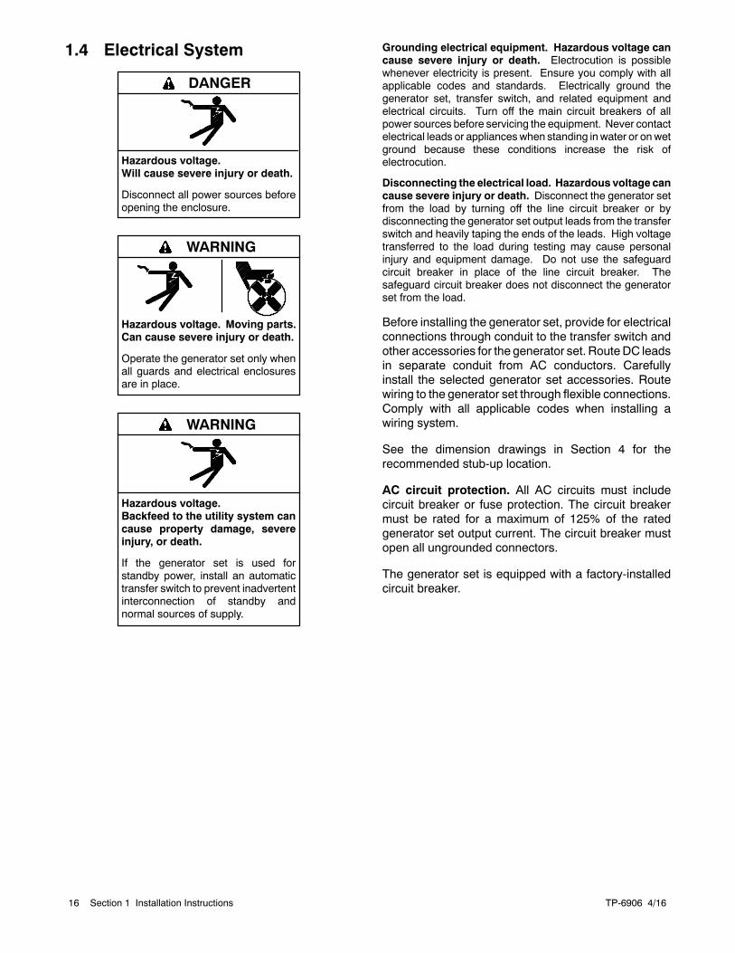
1.4 Electrical System
Hazardous voltage.Will cause severe injury or death.
Disconnect all power sources beforeopening the enclosure.
DANGER
Hazardous voltage.Can cause severe injury or death.
Operate the generator set only whenall guards and electrical enclosuresare in place.
Moving parts.
WARNING
Hazardous voltage.Backfeed to the utility system cancause property damage, severeinjury, or death.
If the generator set is used forstandby power, install an automatictransfer switch to prevent inadvertentinterconnection of standby andnormal sources of supply.
WARNING
Grounding electrical equipment. Hazardous voltage cancause severe injury or death. Electrocution is possiblewhenever electricity is present. Ensure you comply with allapplicable codes and standards. Electrically ground thegenerator set, transfer switch, and related equipment andelectrical circuits. Turn off the main circuit breakers of allpower sources before servicing the equipment. Never contactelectrical leads or applianceswhen standing inwater or onwetground because these conditions increase the risk ofelectrocution.
Disconnecting the electrical load. Hazardous voltage cancause severe injury or death. Disconnect the generator setfrom the load by turning off the line circuit breaker or bydisconnecting the generator set output leads from the transferswitch and heavily taping the ends of the leads. High voltagetransferred to the load during testing may cause personalinjury and equipment damage. Do not use the safeguardcircuit breaker in place of the line circuit breaker. Thesafeguard circuit breaker does not disconnect the generatorset from the load.
Before installing the generator set, provide for electricalconnections through conduit to the transfer switch andother accessories for the generator set. RouteDC leadsin separate conduit from AC conductors. Carefullyinstall the selected generator set accessories. Routewiring to the generator set through flexible connections.Comply with all applicable codes when installing awiring system.
See the dimension drawings in Section 4 for therecommended stub-up location.
AC circuit protection. All AC circuits must includecircuit breaker or fuse protection. The circuit breakermust be rated for a maximum of 125% of the ratedgenerator set output current. The circuit breaker mustopen all ungrounded connectors.
The generator set is equipped with a factory-installedcircuit breaker.
TP-6906 4/16 17Section 1 Installation Instructions
1.4.1 Electrical Connections
Several electrical connections must be made betweenthe generator set and other components of the systemfor proper operation. Most field-installed accessory kitsinclude installation instructions. Comply with applicablenational, state, and local codes when installing a wiringsystem.
For Canadian installations, refer to the CanadianElectrical Code (CEC).
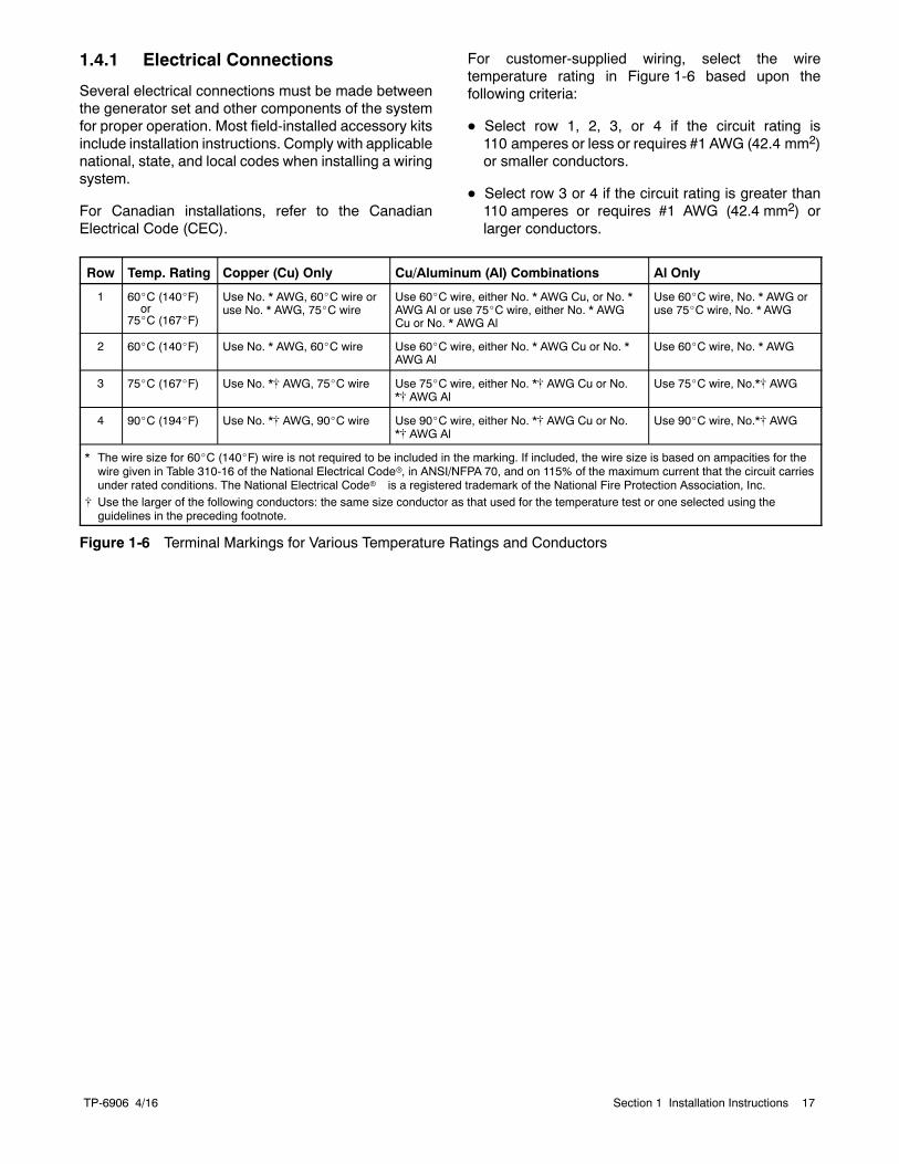
For customer-supplied wiring, select the wiretemperature rating in Figure 1-6 based upon thefollowing criteria:
D Select row 1, 2, 3, or 4 if the circuit rating is110 amperes or less or requires #1 AWG (42.4 mm2)or smaller conductors.
D Select row 3 or 4 if the circuit rating is greater than110 amperes or requires #1 AWG (42.4 mm2) orlarger conductors.
Row Temp. Rating Copper (Cu) Only Cu/Aluminum (Al) Combinations Al Only
1 60_C (140_F)or
75_C (167_F)
Use No. * AWG, 60_C wire oruse No. * AWG, 75_C wire
Use 60_C wire, either No. * AWG Cu, or No. *AWG Al or use 75_C wire, either No. * AWGCu or No. * AWG Al
Use 60_C wire, No. * AWG oruse 75_C wire, No. * AWG
2 60_C (140_F) Use No. * AWG, 60_C wire Use 60_C wire, either No. * AWG Cu or No. *AWG Al
Use 60_C wire, No. * AWG
3 75_C (167_F) Use No. *[ AWG, 75_C wire Use 75_C wire, either No. *[ AWG Cu or No.*[ AWG Al
Use 75_C wire, No.*[ AWG
4 90_C (194_F) Use No. *[ AWG, 90_C wire Use 90_C wire, either No. *[ AWG Cu or No.*[ AWG Al
Use 90_C wire, No.*[ AWG
* The wire size for 60_C (140_F) wire is not required to be included in the marking. If included, the wire size is based on ampacities for thewire given in Table 310-16 of the National Electrical Coder, in ANSI/NFPA 70, and on 115% of the maximum current that the circuit carriesunder rated conditions. The National Electrical Coder is a registered trademark of the National Fire Protection Association, Inc.
[ Use the larger of the following conductors: the same size conductor as that used for the temperature test or one selected using theguidelines in the preceding footnote.
Figure 1-6 Terminal Markings for Various Temperature Ratings and Conductors
TP-6906 4/1618 Section 1 Installation Instructions
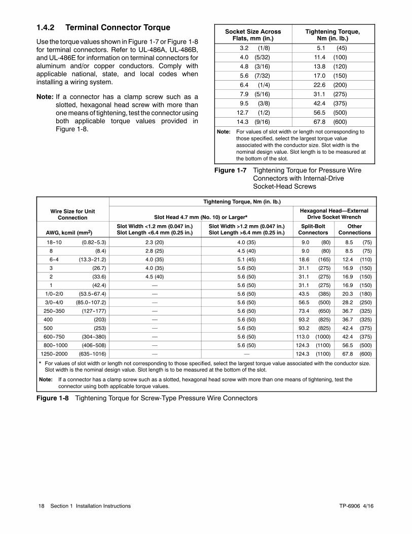
1.4.2 Terminal Connector Torque
Use the torque values shown in Figure 1-7 or Figure 1-8for terminal connectors. Refer to UL-486A, UL-486B,and UL-486E for information on terminal connectors foraluminum and/or copper conductors. Comply withapplicable national, state, and local codes wheninstalling a wiring system.
Note: If a connector has a clamp screw such as aslotted, hexagonal head screw with more thanonemeans of tightening, test the connector usingboth applicable torque values provided inFigure 1-8.
Socket Size AcrossFlats, mm (in.)
Tightening Torque,Nm (in. lb.)
3.2 (1/8) 5.1 (45)
4.0 (5/32) 11.4 (100)
4.8 (3/16) 13.8 (120)
5.6 (7/32) 17.0 (150)
6.4 (1/4) 22.6 (200)
7.9 (5/16) 31.1 (275)
9.5 (3/8) 42.4 (375)
12.7 (1/2) 56.5 (500)
14.3 (9/16) 67.8 (600)
Note: For values of slot width or length not corresponding tothose specified, select the largest torque valueassociated with the conductor size. Slot width is thenominal design value. Slot length is to be measured atthe bottom of the slot.
Figure 1-7 Tightening Torque for Pressure WireConnectors with Internal-DriveSocket-Head Screws
Wire Size for UnitConnection
Tightening Torque, Nm (in. lb.)
Slot Head 4.7 mm (No. 10) or Larger*Hexagonal Head—External
Drive Socket Wrench
AWG, kcmil (mm2)Slot Width <1.2 mm (0.047 in.)Slot Length <6.4 mm (0.25 in.)
Slot Width >1.2 mm (0.047 in.)Slot Length >6.4 mm (0.25 in.)
Split-BoltConnectors
OtherConnections
18--10 (0.82--5.3) 2.3 (20) 4.0 (35) 9.0 (80) 8.5 (75)
8 (8.4) 2.8 (25) 4.5 (40) 9.0 (80) 8.5 (75)
6--4 (13.3--21.2) 4.0 (35) 5.1 (45) 18.6 (165) 12.4 (110)
3 (26.7) 4.0 (35) 5.6 (50) 31.1 (275) 16.9 (150)
2 (33.6) 4.5 (40) 5.6 (50) 31.1 (275) 16.9 (150)
1 (42.4) — 5.6 (50) 31.1 (275) 16.9 (150)
1/0--2/0 (53.5--67.4) — 5.6 (50) 43.5 (385) 20.3 (180)
3/0--4/0 (85.0--107.2) — 5.6 (50) 56.5 (500) 28.2 (250)
250--350 (127--177) — 5.6 (50) 73.4 (650) 36.7 (325)
400 (203) — 5.6 (50) 93.2 (825) 36.7 (325)
500 (253) — 5.6 (50) 93.2 (825) 42.4 (375)
600--750 (304--380) — 5.6 (50) 113.0 (1000) 42.4 (375)
800--1000 (406--508) — 5.6 (50) 124.3 (1100) 56.5 (500)
1250--2000 (635--1016) — — 124.3 (1100) 67.8 (600)
* For values of slot width or length not corresponding to those specified, select the largest torque value associated with the conductor size.Slot width is the nominal design value. Slot length is to be measured at the bottom of the slot.
Note: If a connector has a clamp screw such as a slotted, hexagonal head screw with more than one means of tightening, test theconnector using both applicable torque values.
Figure 1-8 Tightening Torque for Screw-Type Pressure Wire Connectors
TP-6906 4/16 19Section 1 Installation Instructions
1.4.3 Ground and Neutral Connections
Ground the generator set. The grounding method mustcomply with NEC and local codes. Connect the groundto the generator set ground lug, terminal GRD inside thejunction box (see Figure 1-10). Connect the grounds forutility and low voltage connections to the ground lugsprovided in the customer connection box for thosespecific connections (see Figure 1-10).
Various regulations andsite configurations including theNational Electrical Code (NEC), local codes, and thetype of transfer switch used in the application determinethe grounding of the neutral at the alternator. NEC 2002Section 250.20 is one example that has a very goodexplanation of the neutral grounding requirements forgenerator sets.
Generator sets are shipped with the generator setneutral attached to the alternator in the junction box. Atinstallation, the neutral can be grounded at thegenerator set or lifted from the ground stud and isolatedif the installation requires an ungrounded neutralconnection at the alternator. The generator set willoperate properly with the neutral either bonded toground or isolated from ground at the alternator.
1.4.4 Battery Chargers
An engine-driven, battery-charging alternator chargesthe battery whenever the generator set operates.Engine-driven systems can quickly restore the chargeused in a normal cranking cycle.
When the engine is not operating, a very low charge ratefrom an AC-powered battery charger is usuallysufficient to maintain a full charge on the batteries. TheRDC2 controller contains a built-in battery charger to
maintain the generator set’s engine starting battery. Besure to provideACpower for the integral battery chargeras instructed in Section 1.4.5.
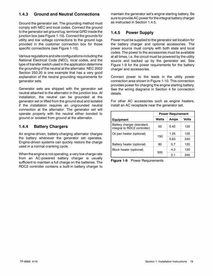
1.4.5 Power Supply
Powermust be supplied to the generator set location forthe battery charger and optional accessories. Thepower source must comply with both state and localcodes. The power to the accessories must be availableat all times, i.e. the circuit must be powered by the utilitysource and backed up by the generator set. SeeFigure 1-9 for the power requirements for the batterycharger and accessories.
Connect power to the leads in the utility powerconnection area shown in Figure 1-10. This connectionprovides power for charging the engine starting battery.See the wiring diagrams in Section 4 for connectiondetails.
For other AC accessories such as engine heaters,install an AC receptacle near the generator set.
Equipment
Power Requirement
Watts Amps Volts
Battery charger (standard,integral to RDC2 controller) 50 0.42 120
Oil pan heater (optional)150
1.25 120
0.63 240
Battery heater (optional) 80 0.7 120
Block heater (optional)500
4.2 120
2.1 240
Figure 1-9 Power Requirements
TP-6906 4/1620 Section 1 Installation Instructions
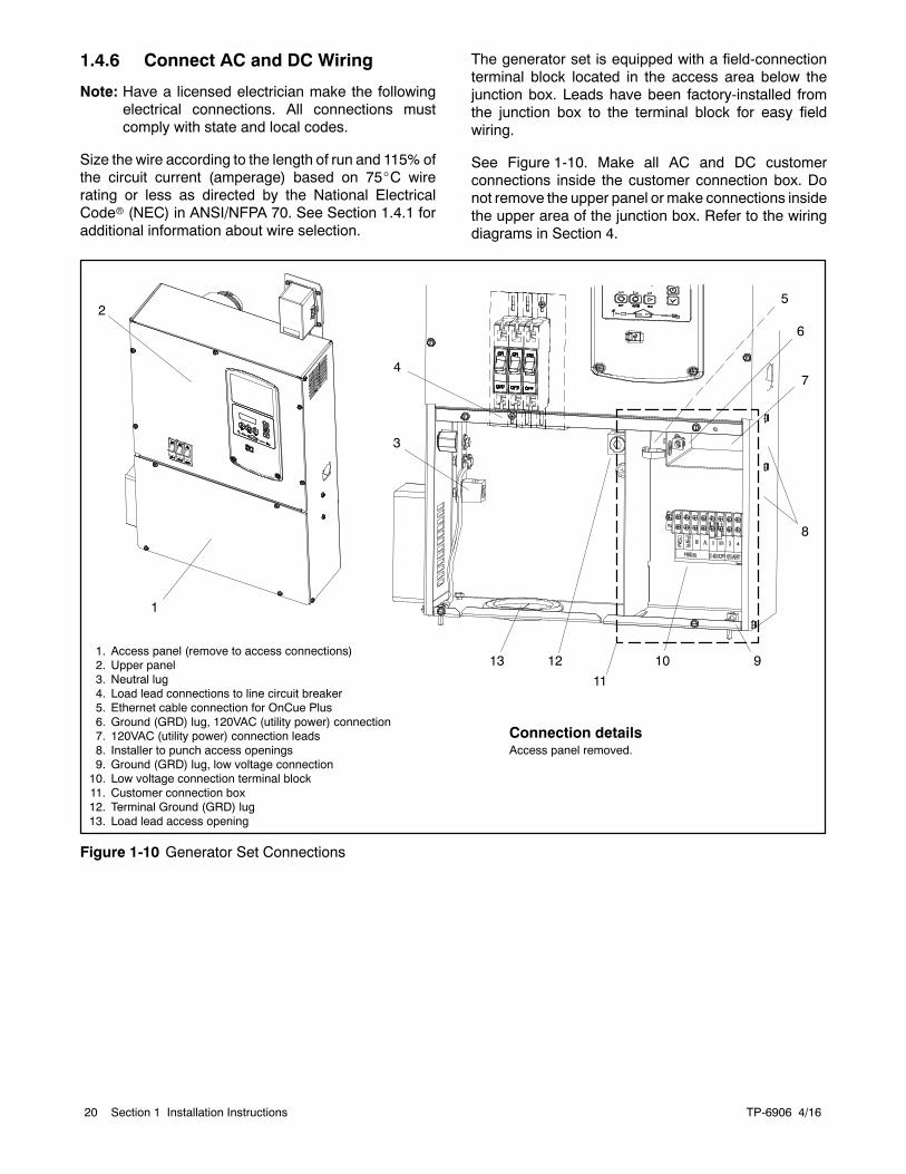
1.4.6 Connect AC and DC Wiring
Note: Have a licensed electrician make the followingelectrical connections. All connections mustcomply with state and local codes.
Size the wire according to the length of run and 115% ofthe circuit current (amperage) based on 75_C wirerating or less as directed by the National ElectricalCoder (NEC) in ANSI/NFPA 70. See Section 1.4.1 foradditional information about wire selection.
The generator set is equipped with a field-connectionterminal block located in the access area below thejunction box. Leads have been factory-installed fromthe junction box to the terminal block for easy fieldwiring.
See Figure 1-10. Make all AC and DC customerconnections inside the customer connection box. Donot remove the upper panel or make connections insidethe upper area of the junction box. Refer to the wiringdiagrams in Section 4.
1. Access panel (remove to access connections)2. Upper panel3. Neutral lug4. Load lead connections to line circuit breaker5. Ethernet cable connection for OnCue Plus6. Ground (GRD) lug, 120VAC (utility power) connection7. 120VAC (utility power) connection leads8. Installer to punch access openings9. Ground (GRD) lug, low voltage connection10. Low voltage connection terminal block11. Customer connection box12. Terminal Ground (GRD) lug13. Load lead access opening
1
Connection detailsAccess panel removed.
12
3
10
4
13
5
7
8
9
6
2
11
Figure 1-10 Generator Set Connections
TP-6906 4/16 21Section 1 Installation Instructions
Generator Set Connections
Use separate conduit for the power cables and the lowvoltage communication or engine start leads. Localcodes and the length of run aswell as the transfer switchwire size requirements will determine the wire sizeneeded for the AC leads.
Note: Some codes require the use of a disconnectswitch. Check the code requirements for yourlocation and install a disconnect switch, ifrequired.
1. Route the load leads into the junction box throughthe access opening in the bottom of the box.Connect the load leads from the line circuit breakerin the generator set junction box to the transferswitch emergency power connection points. SeeFigure 1-10 and refer to transfer switch installationmanual for ATS connection instructions.
2. Connect the neutral (L0) and ground (GRD) leadsfrom the ATS and the main panel to thecorresponding lugs in the connection box. SeeSection 1.4.3 for grounding information.
3. Cut or punchopenings in the side of the connectionbox for the 120 VAC power supply leads and thelow voltage connections. See Figure 1-10. Useseparate conduit for the power leads and the lowvoltage leads.
4. Connect utility power for the controller’s batterycharger. Connect to a circuit that is supplied by theutility source and backed up by the generator. SeeSection 1.4.5 and Figure 1-10 formore informationabout the utility power requirement.
5. For transfer switch communication and/or enginestart connection, see Section 1.4.7.
6. For connection of the optional programmableinterface module (PIM), and/or a load shed kit, seeSection 1.4.9.
7. Install an AC receptacle for the AC accessories, ifequipped. Power to this receptacle must beavailable when the generator set is not running.See Figure 1-9 for accessory power requirements.
8. To connect the OnCuer Plus GeneratorManagement System to your generator, runnetwork cable from the generator set to thecustomer’s router or modem.
a. Route the network cable with otherlow--voltage signal wiring (for example, theRBUS communication leads or engine startleads to the transfer switch), in separateconduit from the AC load leads. If the networkcable is longer than 100 meters (328 ft.), use arepeater or switch.
b. Test the Internet connection for the generatorby connecting a laptop to the network cable.
(1) Turn OFF any wireless connections to thelaptop.
(2) Connect the network cable to the laptop.Connect the other end of the network cableto the customer’s router or modem.
(3) Verify the Internet connection by openingyour web browser and going towww.kohlerpower.com or any knownwebsite.
(4) Disconnect the network cable from thelaptop.
c. Use an RJ45 inline coupler to connect theEthernet cable to the cable in the customerconnection box. The inline coupler is includedwith the OnCue Plus kit.
TP-6906 4/1622 Section 1 Installation Instructions
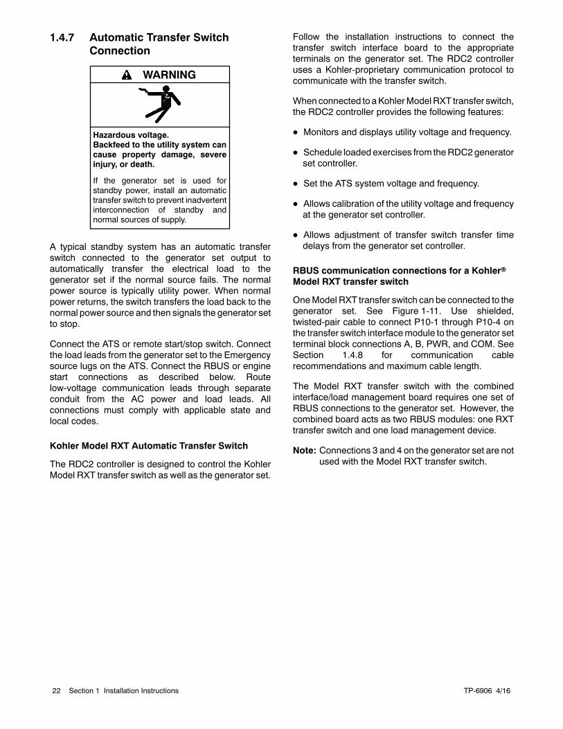
1.4.7 Automatic Transfer SwitchConnection
Hazardous voltage.Backfeed to the utility system cancause property damage, severeinjury, or death.
If the generator set is used forstandby power, install an automatictransfer switch to prevent inadvertentinterconnection of standby andnormal sources of supply.
WARNING
A typical standby system has an automatic transferswitch connected to the generator set output toautomatically transfer the electrical load to thegenerator set if the normal source fails. The normalpower source is typically utility power. When normalpower returns, the switch transfers the load back to thenormal power source and then signals the generator setto stop.
Connect the ATS or remote start/stop switch. Connectthe load leads from the generator set to the Emergencysource lugs on the ATS. Connect the RBUS or enginestart connections as described below. Routelow-voltage communication leads through separateconduit from the AC power and load leads. Allconnections must comply with applicable state andlocal codes.
Kohler Model RXT Automatic Transfer Switch
The RDC2 controller is designed to control the KohlerModel RXT transfer switch as well as the generator set.
Follow the installation instructions to connect thetransfer switch interface board to the appropriateterminals on the generator set. The RDC2 controlleruses a Kohler-proprietary communication protocol tocommunicate with the transfer switch.
Whenconnected to aKohlerModelRXT transfer switch,the RDC2 controller provides the following features:
D Monitors and displays utility voltage and frequency.
D Schedule loadedexercises from theRDC2generatorset controller.
D Set the ATS system voltage and frequency.
D Allows calibration of the utility voltage and frequencyat the generator set controller.
D Allows adjustment of transfer switch transfer timedelays from the generator set controller.
RBUS communication connections for a KohlerrModel RXT transfer switch
OneModel RXT transfer switch can be connected to thegenerator set. See Figure 1-11. Use shielded,twisted-pair cable to connect P10-1 through P10-4 onthe transfer switch interfacemodule to the generator setterminal block connections A, B, PWR, and COM. SeeSection 1.4.8 for communication cablerecommendations and maximum cable length.
The Model RXT transfer switch with the combinedinterface/load management board requires one set ofRBUS connections to the generator set. However, thecombined board acts as two RBUS modules: one RXTtransfer switch and one load management device.
Note: Connections 3 and 4 on the generator set are notused with the Model RXT transfer switch.
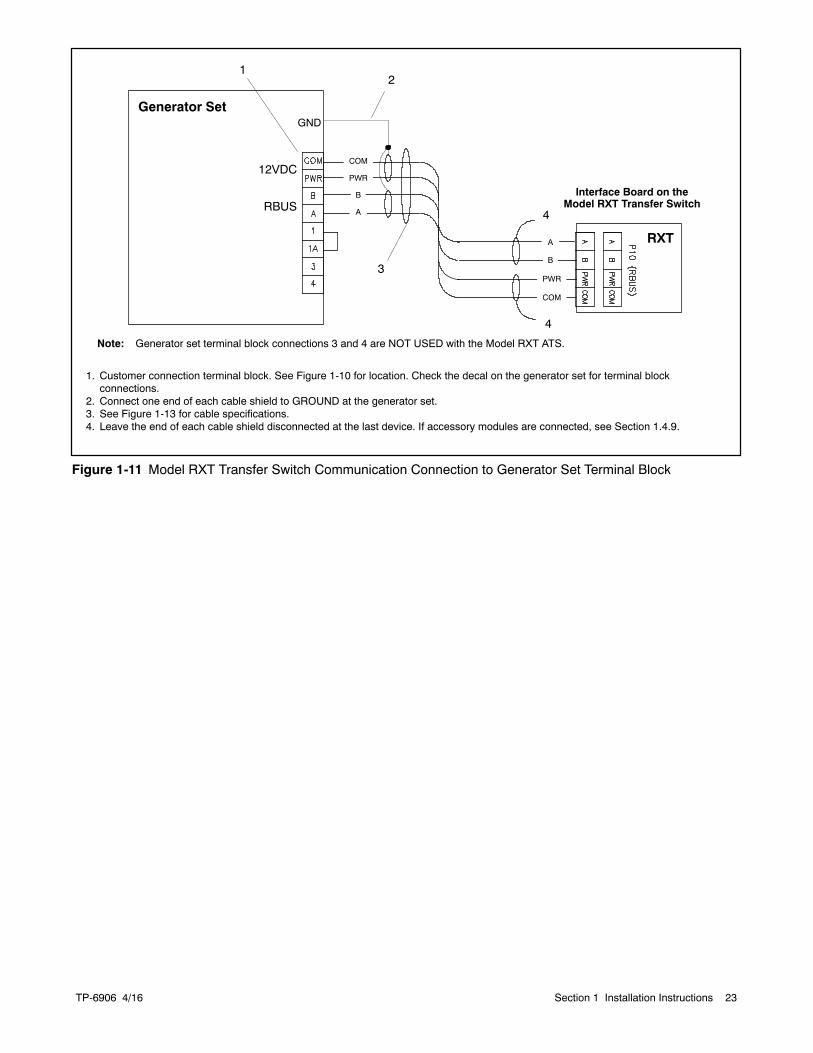
TP-6906 4/16 23Section 1 Installation Instructions
1. Customer connection terminal block. See Figure 1-10 for location. Check the decal on the generator set for terminal blockconnections.
2. Connect one end of each cable shield to GROUND at the generator set.3. See Figure 1-13 for cable specifications.4. Leave the end of each cable shield disconnected at the last device. If accessory modules are connected, see Section 1.4.9.
Interface Board on theModel RXT Transfer Switch
Note: Generator set terminal block connections 3 and 4 are NOT USED with the Model RXT ATS.
Generator Set
COM
PWR
B
A
RXT
COM
PWR
B
A
3
GND
RBUS
12VDC
4
4
21
Figure 1-11 Model RXT Transfer Switch Communication Connection to Generator Set Terminal Block
TP-6906 4/1624 Section 1 Installation Instructions
Engine start connection for other transferswitches or a remote start/stop switch
Note: Do not use the Kohlerr Model RRT transferswitch with Model RCL generator sets.
Other Kohler transfer switches, including Model RDT orModel K (MPACt) transfer switches can be used withthe Kohler generator sets covered in this document.These transfer switches contain separate ATS controlsthat do not communicate with the RDC2 controller.
These transfer switches use a set of contacts to signalthe engine/generator to start. When the normal sourcefails and the generator set is in AUTOmode, the transferswitch contacts close to signal the generator set to startand run. After the normal source returns, the contactsopen to signal the generator set to stop.
The engine start terminals are usually located near thetransfer switch contactor with an engine start decalidentifying the terminals. Use the transfer switch wiringdiagrams to identify the engine start terminals prior tomaking connections.
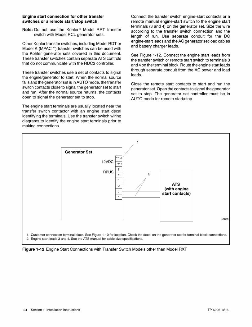
Connect the transfer switch engine-start contacts or aremote manual engine-start switch to the engine startterminals (3 and 4) on the generator set. Size the wireaccording to the transfer switch connection and thelength of run. Use separate conduit for the DCengine-start leads and theACgenerator set load cablesand battery charger leads.
See Figure 1-12. Connect the engine start leads fromthe transfer switch or remote start switch to terminals 3and 4on the terminal block.Route the engine start leadsthrough separate conduit from the AC power and loadleads.
Close the remote start contacts to start and run thegenerator set.Open the contacts to signal the generatorset to stop. The generator set controller must be inAUTO mode for remote start/stop.
tp6809
1. Customer connection terminal block. See Figure 1-10 for location. Check the decal on the generator set for terminal block connections.2. Engine start leads 3 and 4. See the ATS manual for cable size specifications.
Generator Set
ATS(with enginestart contacts)
2
1
RBUS
12VDC
Figure 1-12 Engine Start Connections with Transfer Switch Models other than Model RXT
TP-6906 4/16 25Section 1 Installation Instructions
1.4.8 Communication CableSpecifications
RBUS Connections A and B
For the RBUS communication connections A and B tothe Model RXT transfer switch, optional PIM, and/oroptional load shed kit, use 20 AWG shielded,twisted-pair communication cable. Belden #9402(two-pair) or Belden #8762 (single-pair) or equivalentcable is recommended.
For outdoor installations, including those with buriedcables and/or conduit, use outdoor-rated Belden#1075A or equivalent 20 AWG shielded, twisted-paircommunication cable.
PWR and COM Connections
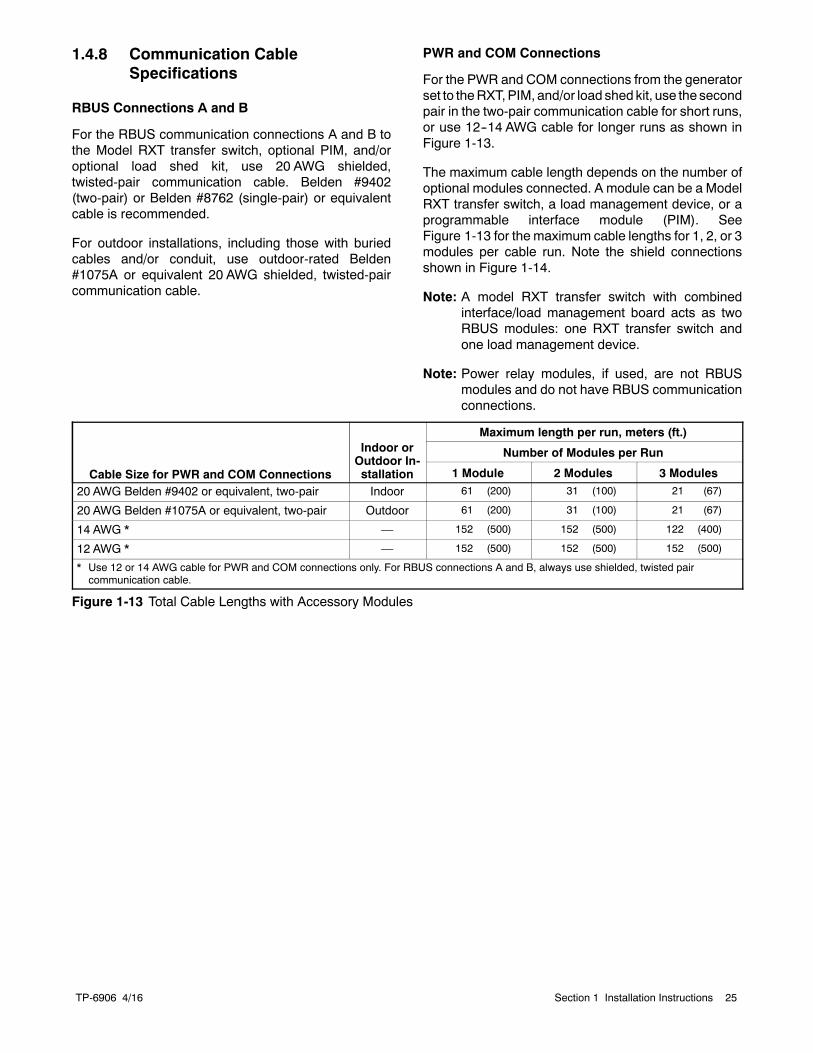
For the PWR and COM connections from the generatorset to theRXT,PIM, and/or load shed kit, use the secondpair in the two-pair communication cable for short runs,or use 12--14 AWG cable for longer runs as shown inFigure 1-13.
The maximum cable length depends on the number ofoptional modules connected. A module can be a ModelRXT transfer switch, a load management device, or aprogrammable interface module (PIM). SeeFigure 1-13 for the maximum cable lengths for 1, 2, or 3modules per cable run. Note the shield connectionsshown in Figure 1-14.
Note: A model RXT transfer switch with combinedinterface/load management board acts as twoRBUS modules: one RXT transfer switch andone load management device.
Note: Power relay modules, if used, are not RBUSmodules and do not have RBUS communicationconnections.
Cable Size for PWR and COM Connections
Indoor orOutdoor In-stallation
Maximum length per run, meters (ft.)
Number of Modules per Run
1 Module 2 Modules 3 Modules
20 AWG Belden #9402 or equivalent, two-pair Indoor 61 (200) 31 (100) 21 (67)
20 AWG Belden #1075A or equivalent, two-pair Outdoor 61 (200) 31 (100) 21 (67)
14 AWG * — 152 (500) 152 (500) 122 (400)
12 AWG * — 152 (500) 152 (500) 152 (500)
* Use 12 or 14 AWG cable for PWR and COM connections only. For RBUS connections A and B, always use shielded, twisted paircommunication cable.
Figure 1-13 Total Cable Lengths with Accessory Modules
TP-6906 4/1626 Section 1 Installation Instructions
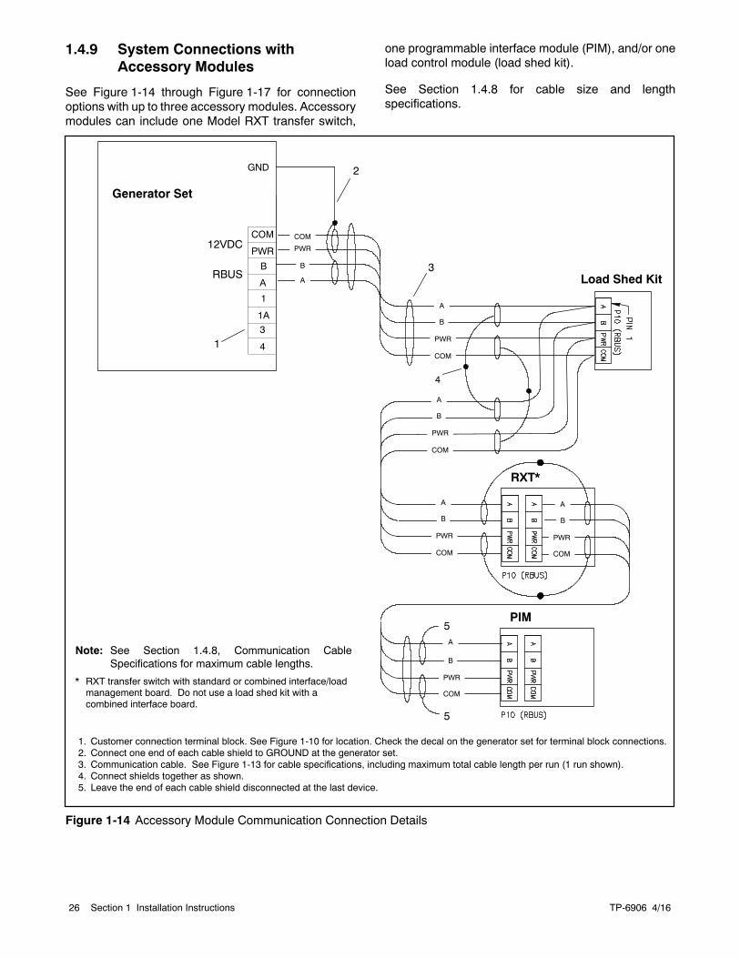
1.4.9 System Connections withAccessory Modules
See Figure 1-14 through Figure 1-17 for connectionoptions with up to three accessory modules. Accessorymodules can include one Model RXT transfer switch,
one programmable interface module (PIM), and/or oneload control module (load shed kit).
See Section 1.4.8 for cable size and lengthspecifications.
Generator Set
GND
A
B
COM
PWR
1A
1
RBUS
12VDC
RXT*
COM
COM
PWR
COM
PWR
PWR
B
A
B
A
B
A
COM
PWR
B
A
COM
PWR
B
A
4
5
2
1
3
5
Load Shed Kit
PIM
COM
PWR
B
A
Note: See Section 1.4.8, Communication CableSpecifications for maximum cable lengths.
* RXT transfer switch with standard or combined interface/loadmanagement board. Do not use a load shed kit with acombined interface board.
1. Customer connection terminal block. See Figure 1-10 for location. Check the decal on the generator set for terminal block connections.2. Connect one end of each cable shield to GROUND at the generator set.3. Communication cable. See Figure 1-13 for cable specifications, including maximum total cable length per run (1 run shown).4. Connect shields together as shown.5. Leave the end of each cable shield disconnected at the last device.
4
3
Figure 1-14 Accessory Module Communication Connection Details
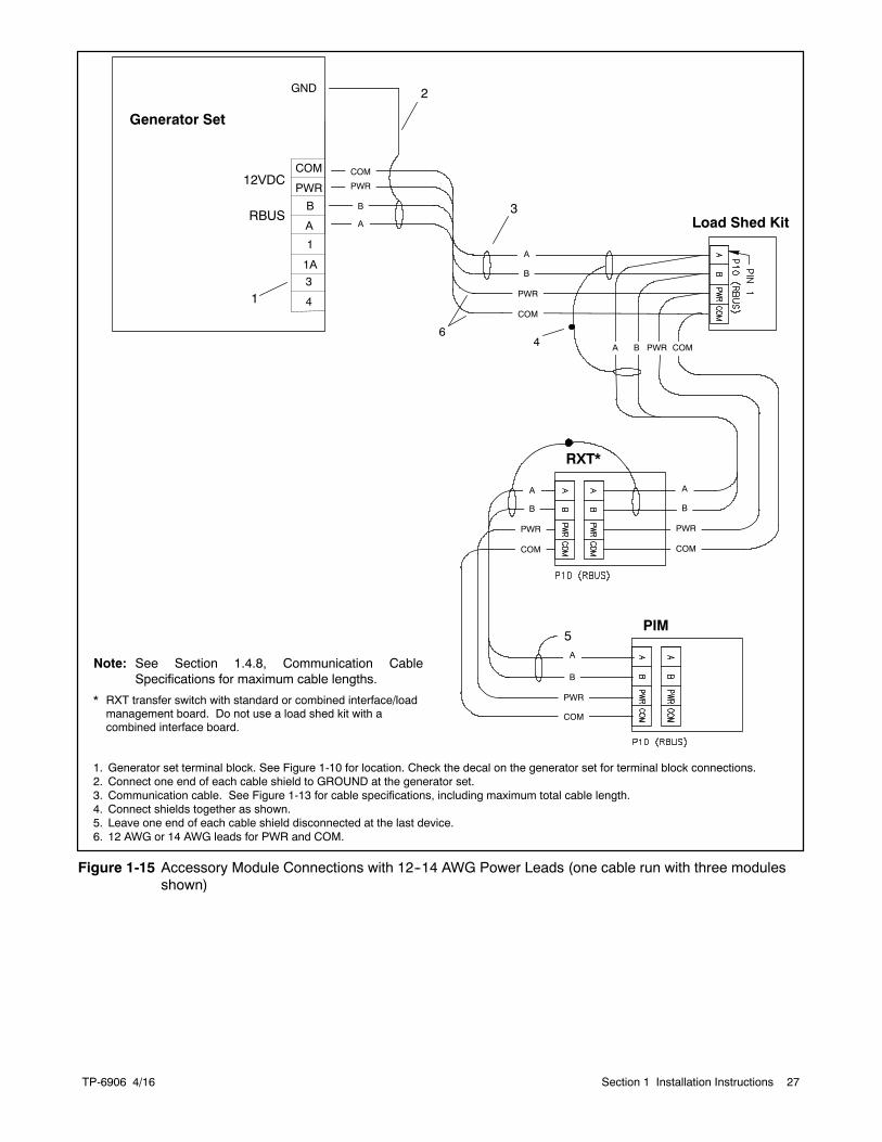
TP-6906 4/16 27Section 1 Installation Instructions
RXT*
COM
COM
PWR
COM
PWR
PWR
B
A
B
A
B
A
COM
PWR
B
A
COM
PWR
B
A
4
2
3
5
Load Shed Kit
PIM
COMA PWRB
1. Generator set terminal block. See Figure 1-10 for location. Check the decal on the generator set for terminal block connections.2. Connect one end of each cable shield to GROUND at the generator set.3. Communication cable. See Figure 1-13 for cable specifications, including maximum total cable length.4. Connect shields together as shown.5. Leave one end of each cable shield disconnected at the last device.6. 12 AWG or 14 AWG leads for PWR and COM.
Note: See Section 1.4.8, Communication CableSpecifications for maximum cable lengths.
* RXT transfer switch with standard or combined interface/loadmanagement board. Do not use a load shed kit with acombined interface board.
6
Generator Set
GND
A
B
COM
PWR
1A
1
RBUS
12VDC
1 4
3
Figure 1-15 Accessory Module Connections with 12--14 AWG Power Leads (one cable run with three modulesshown)
TP-6906 4/1628 Section 1 Installation Instructions
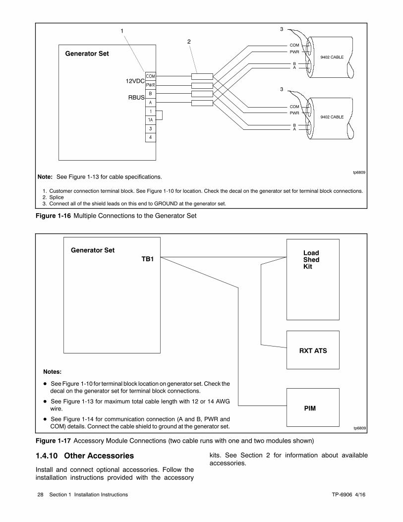
Note: See Figure 1-13 for cable specifications.
1. Customer connection terminal block. See Figure 1-10 for location. Check the decal on the generator set for terminal block connections.2. Splice3. Connect all of the shield leads on this end to GROUND at the generator set.
2
tp6809
Generator SetCOM
PWR
BA
3
COM
PWR
BA
9402 CABLE
9402 CABLE
RBUS
12VDC3
1
Figure 1-16 Multiple Connections to the Generator Set
tp6809
Generator SetTB1
Notes:
D SeeFigure 1-10 for terminal block locationongenerator set. Check thedecal on the generator set for terminal block connections.
D See Figure 1-13 for maximum total cable length with 12 or 14 AWGwire.
D See Figure 1-14 for communication connection (A and B, PWR andCOM) details. Connect the cable shield to ground at the generator set.
PIM
RXT ATS
LoadShedKit
Figure 1-17 Accessory Module Connections (two cable runs with one and two modules shown)
1.4.10 Other Accessories
Install and connect optional accessories. Follow theinstallation instructions provided with the accessory
kits. See Section 2 for information about availableaccessories.

TP-6906 4/16 29Section 1 Installation Instructions
1.5 Engine Starting Battery
Sulfuric acid in batteries.Can cause severe injury or death.
Wear protective goggles andclothing. Battery acid may causeblindness and burn skin.
WARNING
Explosion.Can cause severe injury or death.Relays in the battery chargercause arcs or sparks.
Locate the battery in a well-ventilatedarea. Isolate the battery charger fromexplosive fumes.
WARNING
Battery gases. Explosion can cause severe injury ordeath. Battery gases can cause an explosion. Do not smokeor permit flames or sparks to occur near a battery at any time,particularly when it is charging. Do not dispose of a battery in afire. To prevent burns and sparks that could cause anexplosion, avoid touching the battery terminals with tools orother metal objects. Remove all jewelry before servicing theequipment. Discharge static electricity from your body beforetouching batteries by first touching a grounded metal surfaceaway from the battery. To avoid sparks, do not disturb thebattery charger connections while the battery is charging.Always turn the battery charger off before disconnecting thebattery connections. Ventilate the compartments containingbatteries to prevent accumulation of explosive gases.
Battery short circuits. Explosion can cause severe injuryor death. Short circuits can cause bodily injury and/orequipment damage. Disconnect the battery before generatorset installation or maintenance. Remove all jewelry beforeservicing the equipment. Use tools with insulated handles.Remove the negative (--) lead first when disconnecting thebattery. Reconnect the negative (--) lead last whenreconnecting the battery. Never connect the negative (--)battery cable to the positive (+) connection terminal of thestarter solenoid. Do not test the battery condition by shortingthe terminals together.
Battery electrolyte is a diluted sulfuric acid. Battery acidcan cause severe injury or death. Battery acid can causeblindness and burn skin. Always wear splashproof safetygoggles, rubber gloves, and boots when servicing the battery.Do not open a sealed battery or mutilate the battery case. Ifbattery acid splashes in the eyes or on the skin, immediatelyflush the affected area for 15 minutes with large quantities ofclean water. Seek immediate medical aid in the case of eyecontact. Never add acid to a battery after placing the battery inservice, as this may result in hazardous spattering of batteryacid.
Battery acid cleanup. Battery acid can cause severeinjury or death. Battery acid is electrically conductive andcorrosive. Add 500 g (1 lb.) of bicarbonate of soda (bakingsoda) to a container with 4 L (1 gal.) of water and mix theneutralizing solution. Pour the neutralizing solution on thespilled battery acid and continue to add the neutralizingsolution to the spilled battery acid until all evidence of achemical reaction (foaming) has ceased. Flush the resultingliquid with water and dry the area.
Use a BCI group 24 size 12-volt battery with a minimumrating of 630 cold cranking amps (CCA) at 0_F.
1. Ensure that the starting battery is fully chargedbefore placing the battery in service.
2. Clean the battery posts and/or adapters ifnecessary.
3. Install battery post adapters, if needed.
4. See the dimension drawing in Section 4 for thebattery rack location. Place the battery on thebattery rack on the skid.
5. Connect the red battery cable to the positive (+)battery terminal.
6. Connect the black battery cable to the negative (--)battery terminal.
7. Place the boots over the battery terminals.
When power is applied to the RDC2 controller (that is,when the battery is connected), you will be prompted toset the date and time, and then to set the exerciser. SeeSection 1.9 and the generator set operation manual forinstructions.
If the battery is disconnected for service or replacement,the exercise settings on the RDC2/DC2 controller arelost. Set the exerciser after installing and connecting thebattery. See Section 1.9, Set Exerciser.
TP-6906 4/1630 Section 1 Installation Instructions
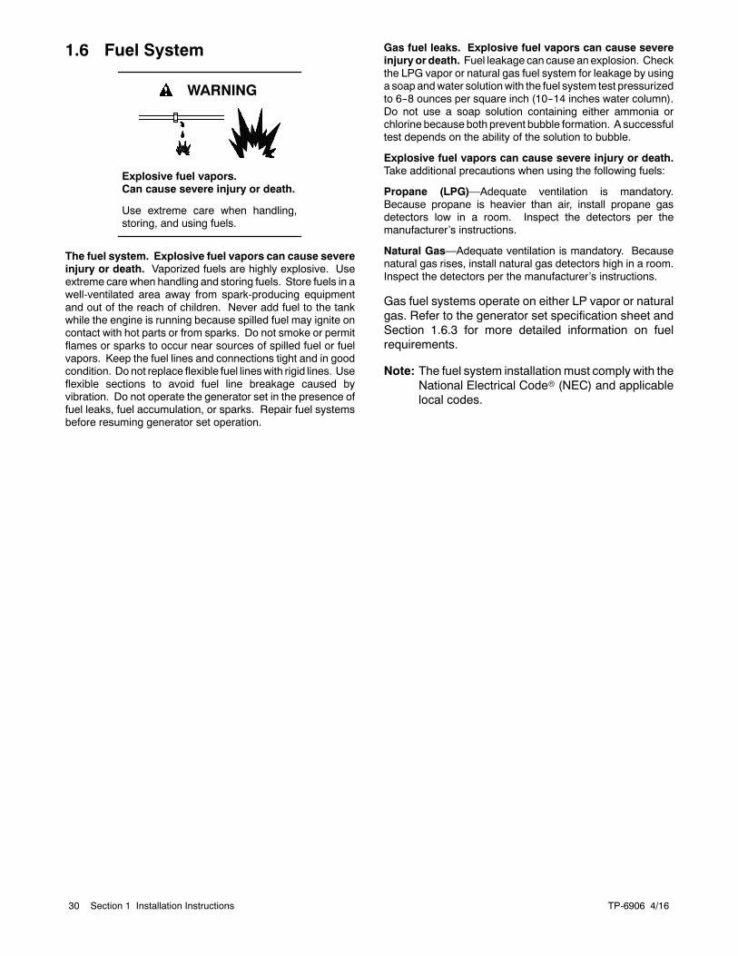
1.6 Fuel System
Explosive fuel vapors.Can cause severe injury or death.
Use extreme care when handling,storing, and using fuels.
WARNING
The fuel system. Explosive fuel vapors can cause severeinjury or death. Vaporized fuels are highly explosive. Useextreme care when handling and storing fuels. Store fuels in awell-ventilated area away from spark-producing equipmentand out of the reach of children. Never add fuel to the tankwhile the engine is running because spilled fuel may ignite oncontact with hot parts or from sparks. Do not smoke or permitflames or sparks to occur near sources of spilled fuel or fuelvapors. Keep the fuel lines and connections tight and in goodcondition. Donot replace flexible fuel lineswith rigid lines. Useflexible sections to avoid fuel line breakage caused byvibration. Do not operate the generator set in the presence offuel leaks, fuel accumulation, or sparks. Repair fuel systemsbefore resuming generator set operation.
Gas fuel leaks. Explosive fuel vapors can cause severeinjury or death. Fuel leakage can cause anexplosion. Checkthe LPG vapor or natural gas fuel system for leakage by usinga soap andwater solutionwith the fuel system test pressurizedto 6--8 ounces per square inch (10--14 inches water column).Do not use a soap solution containing either ammonia orchlorine because both prevent bubble formation. A successfultest depends on the ability of the solution to bubble.
Explosive fuel vapors can cause severe injury or death.Take additional precautions when using the following fuels:
Propane (LPG)—Adequate ventilation is mandatory.Because propane is heavier than air, install propane gasdetectors low in a room. Inspect the detectors per themanufacturer’s instructions.
Natural Gas—Adequate ventilation is mandatory. Becausenatural gas rises, install natural gas detectors high in a room.Inspect the detectors per the manufacturer’s instructions.
Gas fuel systems operate on either LP vapor or naturalgas. Refer to the generator set specification sheet andSection 1.6.3 for more detailed information on fuelrequirements.
Note: The fuel system installationmust comply with theNational Electrical Coder (NEC) and applicablelocal codes.
TP-6906 4/16 31Section 1 Installation Instructions
1.6.1 Fuel Lines
Gas lines. Never use fuel piping to ground electricalequipment. The gas supplier is responsible forinstallation, repair, and alteration to gas piping.
Use Schedule 40 black-iron pipe for gas piping. Coppertubingmaybeused if the fuel doesnot contain hydrogensulfide or other ingredients that react chemically withcopper.
Line size. Size piping according to the requirements ofthe equipment. The type of fuel, the distance it musttravel from gas meter/tank to fuel shutoff solenoid, andthe amount consumed by the engine must beconsidered when determining fuel line pipe size.
In addition to actual fuel consumption, consider thefollowing pressure loss factors:
D Pipe lengthD Other appliances on the same fuel supplyD Number of fittings
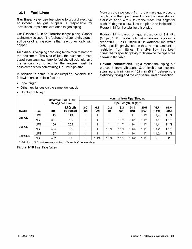
Measure the pipe length from the primary gas pressureregulator to the pipe connection on the generator setfuel inlet. Add 2.4 m (8 ft.) to the measured length foreach 90 degree elbow. Use the pipe size indicated inFigure 1-18 for the total length of pipe.
Figure 1-18 is based on gas pressures of 3.4 kPa(0.5 psi, 13.8 in. water column) or less and a pressuredrop of 0.12 kPa (0.018 psi, 0.5 in. water column) with a0.60 specific gravity and with a normal amount ofrestriction from fittings. The LPG flow has beencorrected for specific gravity to determine the pipe sizesshown in the table.
Flexible connections. Rigid mount the piping butprotect it from vibration. Use flexible connectionsspanning a minimum of 152 mm (6 in.) between thestationary piping and the engine fuel inlet connection.
Model Fuel
Maximum Fuel FlowRate@ Full Load
Nominal Iron Pipe Size, in.
Pipe Length, m (ft) *
cfhLPG cfhcorrected
3.0(10)
6.1(20)
12.2(40)
18.3(60)
24.4(80)
30.5(100)
45.7(150)
61.0(200)
24RCLLPG 113 179 1 1 1 1 1 1 1/4 1 1/4 1 1/4
NG 301 NA 1 1 1 1 1/4 1 1/4 1 1/4 1 1/4 1 1/2
30RCLLPG 166 262 1 1 1 1 1/4 1 1/4 1 1/4 1 1/4 1 1/4
NG 424 NA 1 1 1 1/4 1 1/4 1 1/4 1 1/2 1 1/2 1 1/2
38RCLBLPG 197 311 1 1 1 1 1/4 1 1/4 1 1/4 1 1/2 1 1/2
NG 492 NA 1 1 1/4 1 1/4 1 1/2 1 1/2 1 1/2 2 2
* Add 2.4 m (8 ft.) to the measured length for each 90 degree elbow.
Figure 1-18 Fuel Pipe Sizes
TP-6906 4/1632 Section 1 Installation Instructions
1.6.2 Gas Regulators
Gas regulators reduce high incoming fuel pressures tolower levels acceptable for engines. See the generatorset specification sheet for fuel supply pressurerequirements.
Primary gas regulator. The primary regulator reducesthe high pressure from a tank or transmission line to thelower pressure required by the secondary regulator onthe engine. The fuel supplier provides the primaryregulator. The fuel supplier is also responsible forproviding sufficient gas pressure to operate the primaryregulator.
Secondary gas regulator. The secondary regulator isfactory-installed on the generator set engine andcontrols the inlet pressure to the engine.
1.6.3 Install and Connect Fuel Supply
Note: Have the fuel piping and regulator installed by thefuel supplier. The fuel supply installation mustcomply with NEC and local codes.
1. See the generator set spec sheet for the fuelsupply requirements. Add up the fuel requirementsfor the generator set plus all other gas-firedequipment fueled by the same supply.
2. Check that the primary regulator and gas meterhave sufficient capacity for the fuel requirementsfor the generator set plus all other gas-firedequipment. Have the fuel supplier install a largergas meter, if necessary.
3. Determine the fuel pipe size as described inSection 1.6.1.
4. Have your fuel supplier install amanual fuel shutoffvalve and rigid gas piping. Bring the pipe to within254 mm (10 in.) of the generator set fuel inletlocation.
5. Remove the enclosure door on the service side ofthe unit.
6. Connect the fuel supply:
a. Apply pipe sealant that is approved for fuelconnections to the threaded fuel connections.
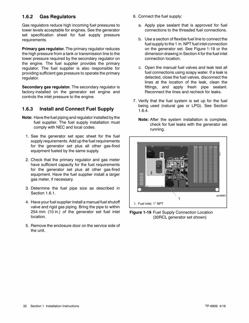
b. Use a section of flexible fuel line to connect thefuel supply to the 1 in. NPT fuel inlet connectionon the generator set. See Figure 1-19 or thedimension drawing in Section 4 for the fuel inletconnection location.
c. Open the manual fuel valves and leak test allfuel connections using soapy water. If a leak isdetected, close the fuel valves, disconnect thelines at the location of the leak, clean thefittings, and apply fresh pipe sealant.Reconnect the lines and recheck for leaks.
7. Verify that the fuel system is set up for the fuelbeing used (natural gas or LPG). See Section1.6.4.
Note: After the system installation is complete,check for fuel leaks with the generator setrunning.
adv8663
1. Fuel inlet, 1” NPT1
Figure 1-19 Fuel Supply Connection Location(30RCL generator set shown)
TP-6906 4/16 33Section 1 Installation Instructions
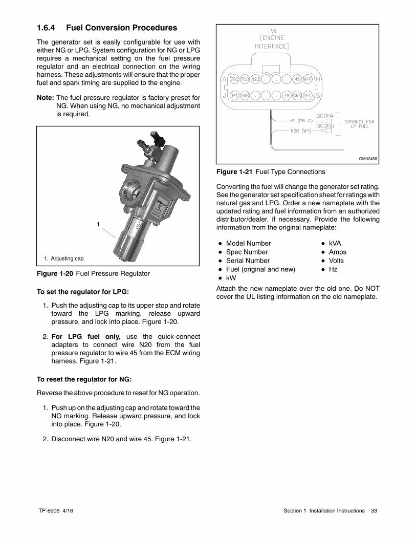
1.6.4 Fuel Conversion Procedures
The generator set is easily configurable for use witheither NG or LPG. System configuration for NG or LPGrequires a mechanical setting on the fuel pressureregulator and an electrical connection on the wiringharness. These adjustments will ensure that the properfuel and spark timing are supplied to the engine.
Note: The fuel pressure regulator is factory preset forNG. When using NG, no mechanical adjustmentis required.
1
1. Adjusting cap
Figure 1-20 Fuel Pressure Regulator
To set the regulator for LPG:
1. Push the adjusting cap to its upper stop and rotatetoward the LPG marking, release upwardpressure, and lock into place. Figure 1-20.
2. For LPG fuel only, use the quick-connectadapters to connect wire N20 from the fuelpressure regulator to wire 45 from the ECM wiringharness. Figure 1-21.
To reset the regulator for NG:
Reverse the above procedure to reset for NGoperation.
1. Push up on the adjusting cap and rotate toward theNG marking. Release upward pressure, and lockinto place. Figure 1-20.
2. Disconnect wire N20 and wire 45. Figure 1-21.
GM92458
Figure 1-21 Fuel Type Connections
Converting the fuel will change the generator set rating.See thegenerator set specification sheet for ratingswithnatural gas and LPG. Order a new nameplate with theupdated rating and fuel information from an authorizeddistributor/dealer, if necessary. Provide the followinginformation from the original nameplate:
D Model Number D kVAD Spec Number D AmpsD Serial Number D VoltsD Fuel (original and new) D HzD kW
Attach the new nameplate over the old one. Do NOTcover the UL listing information on the old nameplate.
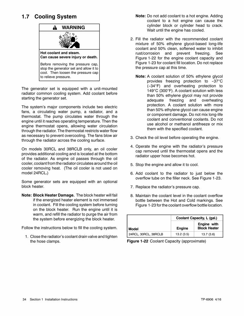
TP-6906 4/1634 Section 1 Installation Instructions
1.7 Cooling System
Hot coolant and steam.Can cause severe injury or death.
Before removing the pressure cap,stop the generator set and allow it tocool. Then loosen the pressure capto relieve pressure.
WARNING
The generator set is equipped with a unit-mountedradiator common cooling system. Add coolant beforestarting the generator set.
The system’s major components include two electricfans, a circulating water pump, a radiator, and athermostat. The pump circulates water through theengine until it reaches operating temperature. Then theengine thermostat opens, allowing water circulationthrough the radiator. The thermostat restricts water flowas necessary to prevent overcooling. The fans blow airthrough the radiator across the cooling surface.
On models 30RCL and 38RCLB only, an oil coolerprovides additional cooling and is located at the bottomof the radiator. As engine oil passes through the oilcooler, coolant from the radiator circulates around theoilcooler removing heat. (The oil cooler is not used onmodel 24RCL.)
Some generator sets are equipped with an optionalblock heater.
Note: BlockHeater Damage. The block heater will failif the energized heater element is not immersedin coolant. Fill the cooling system before turningon the block heater. Run the engine until it iswarm, and refill the radiator to purge the air fromthe system before energizing the block heater.
Follow the instructions below to fill the cooling system.
1. Close the radiator’s coolant drain valve and tightenthe hose clamps.
Note: Do not add coolant to a hot engine. Addingcoolant to a hot engine can cause thecylinder block or cylinder head to crack.Wait until the engine has cooled.
2. Fill the radiator with the recommended coolantmixture of 50% ethylene glycol-based long-lifecoolant and 50% clean, softened water to inhibitrust/corrosion and prevent freezing. SeeFigure 1-22 for the engine coolant capacity andFigure 1-23 for coolant fill location. Do not replacethe pressure cap at this time.
Note: A coolant solution of 50% ethylene glycolprovides freezing protection to --37C(--34F) and overheating protection to149C (300F). A coolant solution with lessthan 50% ethylene glycol may not provideadequate freezing and overheatingprotection. A coolant solution with morethan 50% ethylene glycol can cause engineor component damage. Do not mix long-lifecoolant and conventional coolants. Do notuse alcohol or methanol antifreeze or mixthem with the specified coolant.
3. Check the oil level before operating the engine.
4. Operate the engine with the radiator’s pressurecap removed until the thermostat opens and theradiator upper hose becomes hot.
5. Stop the engine and allow it to cool.
6. Add coolant to the radiator to just below theoverflow tube on the filler neck. See Figure 1-23.
7. Replace the radiator’s pressure cap.
8. Maintain the coolant level in the coolant overflowbottle between the Hot and Cold markings. SeeFigure 1-23 for the coolant overflow bottle location.
Model
Coolant Capacity, L (gal.)
EngineEngine withBlock Heater
24RCL, 30RCL, 38RCLB 13.2 (3.5) 13.7 (3.6)
Figure 1-22 Coolant Capacity (approximate)
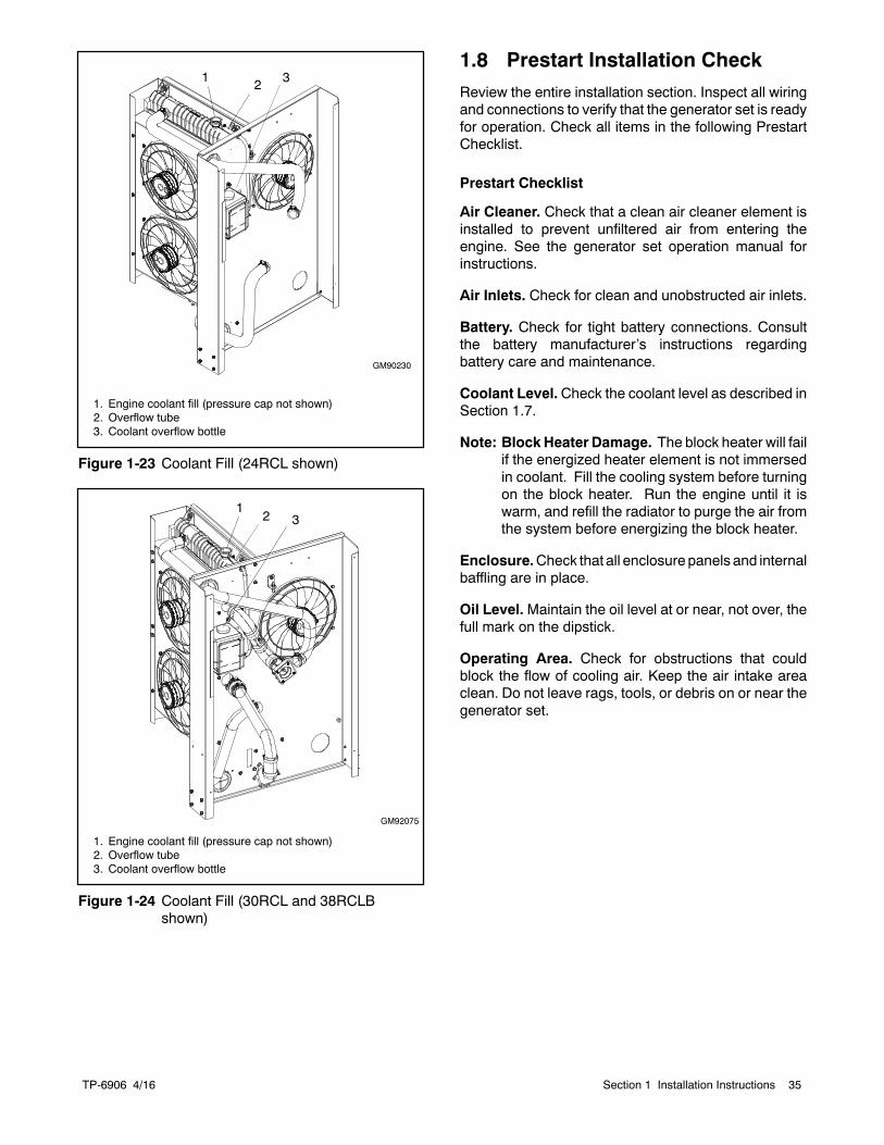
TP-6906 4/16 35Section 1 Installation Instructions
1. Engine coolant fill (pressure cap not shown)2. Overflow tube3. Coolant overflow bottle
31 2
GM90230
Figure 1-23 Coolant Fill (24RCL shown)
3
1. Engine coolant fill (pressure cap not shown)2. Overflow tube3. Coolant overflow bottle
12
GM92075
Figure 1-24 Coolant Fill (30RCL and 38RCLBshown)
1.8 Prestart Installation CheckReview the entire installation section. Inspect all wiringand connections to verify that the generator set is readyfor operation. Check all items in the following PrestartChecklist.
Prestart Checklist
Air Cleaner. Check that a clean air cleaner element isinstalled to prevent unfiltered air from entering theengine. See the generator set operation manual forinstructions.
Air Inlets. Check for clean and unobstructed air inlets.
Battery. Check for tight battery connections. Consultthe battery manufacturer’s instructions regardingbattery care and maintenance.
Coolant Level.Check the coolant level as described inSection 1.7.
Note: BlockHeater Damage. The block heater will failif the energized heater element is not immersedin coolant. Fill the cooling system before turningon the block heater. Run the engine until it iswarm, and refill the radiator to purge the air fromthe system before energizing the block heater.
Enclosure.Check that all enclosurepanels and internalbaffling are in place.
Oil Level.Maintain the oil level at or near, not over, thefull mark on the dipstick.
Operating Area. Check for obstructions that couldblock the flow of cooling air. Keep the air intake areaclean. Do not leave rags, tools, or debris on or near thegenerator set.

TP-6906 4/1636 Section 1 Installation Instructions
1.9 Set ExerciserWhen power is applied to the RDC2 controller (that is,when the battery is connected), you will be prompted toset the date and time, and then to set the exerciser. Setthe exerciser to automatically run the generator set onthe desired day and time every week or every twoweeks.
Figure 1-25 shows the controller screens. The firstsetting will flash. Press the Up and Down arrow buttonsto change the setting. Press Select to save the settingandmove on to the next. Repeat until the date, time, andexercise are set and the controller display shows themain menu. See TP-6905, Generator Set OperationManual, for more detailed instructions to set the dateand time and set the exerciser.
tp6803
Date:
05Dec2011
Time:
08:31a
Next Exercise:
08:31a 12Dec2011
Setting will flash.
Press the up and down arrowbuttons to change the setting.
Press Select to save the set-ting.
Figure 1-25 Set Date, Time, and Exercise, RDC2Controller
In order to set a loaded exercise using the RDC2controller, a KohlerrModel RXT transfer switchmust beconnected. To set a loaded exercise on a generator setconnected to a transfer switch other than a Model RXT,use the transfer switch controller to set the exercise.Refer to the transfer switch operation manual forinstructions.
The controller must be in automatic mode for theexerciser to operate as scheduled. Press AUTO toplace the generator set controller into automatic mode.
1.10 Operation Tests
Hazardous voltage.Can cause severe injury or death.
Operate the generator set only whenall guards and electrical enclosuresare in place.
Moving parts.
WARNING
1. Verify that all guards are in place. Install theenclosure’s end panels and nonservice side door.
2. Check the items in the Prestart Checklist in thegenerator set operation manual.
3. Set the time and date, and then set the exerciser torun the generator set once a week or every otherweek to keep the generator set in good operatingcondition. See TP-6905, Operation Manual, forinstructions to set the date and time and set theexerciser.
4. Press the RUN button on the generator setcontroller to start the generator set.
5. Use a digital voltmeter (DVM) to check the outputvoltage from the generator set. If voltagecalibration is required, refer to Section 3.5 forinstructions.
6. Press OFF to stop the engine. Then press AUTOon the RDC2 controller.
7. Install the enclosure’s service-side door. Verify thatall enclosure doors and panels are installed. Lockthe enclosure doors to prevent unauthorizedaccess.
TP-6906 4/16 37Section 1 Installation Instructions
1.11 OnCue Plus GeneratorManagement System
The OnCuer Plus Generator Management System isincluded with model 24RCL, 30RCL, and 38RCLBgenerators. OnCue Plus allows monitoring and controlof your generator set from a personal computer, smartphone, or tablet. OnCue Plus can also be configured tosend email or text message notifications in the event ofa generator set fault. See G18-247, Quick Start Guideand TP--6928, OnCue Plus Operation Manual, forinstructions.
To use OnCue Plus, you must have the followingminimum requirements for connecting your generator tothe Internet:
D “Always-on” Internet service for generator setconnection (for example, cable, DSL, or phone linemodem connected 24 hours)
D Unused Ethernet port on a switch, router, or modem
D An uninterruptible power supply (UPS) for themodem and router is recommended.
D 5E customer-supplied network cable for connectionof the generator set to the customer’s Ethernet router(see installation instructions in Section 1.4.6)
D USB cable, male USB A to male mini-B, for updatingthe controller firmware.
For instructions on connecting the network cables to thegenerator set, see instructions in Section 1.4.6.

TP-6906 4/1638 Section 1 Installation Instructions
Notes
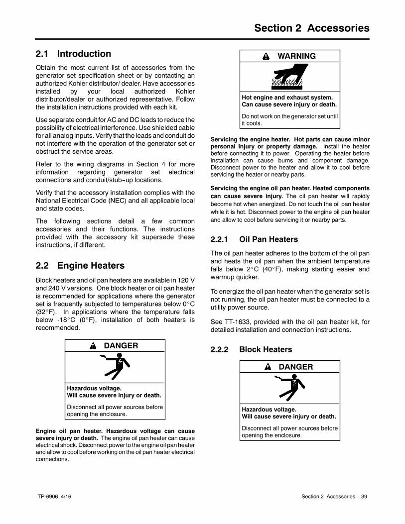
TP-6906 4/16 39Section 2 Accessories
Section 2 Accessories
2.1 IntroductionObtain the most current list of accessories from thegenerator set specification sheet or by contacting anauthorized Kohler distributor/ dealer. Have accessoriesinstalled by your local authorized Kohlerdistributor/dealer or authorized representative. Followthe installation instructions provided with each kit.
Use separate conduit for ACandDC leads to reduce thepossibility of electrical interference. Use shielded cablefor all analog inputs. Verify that the leads and conduit donot interfere with the operation of the generator set orobstruct the service areas.
Refer to the wiring diagrams in Section 4 for moreinformation regarding generator set electricalconnections and conduit/stub--up locations.
Verify that the accessory installation complies with theNational Electrical Code (NEC) and all applicable localand state codes.
The following sections detail a few commonaccessories and their functions. The instructionsprovided with the accessory kit supersede theseinstructions, if different.
2.2 Engine HeatersBlock heaters and oil pan heaters are available in 120 Vand 240 V versions. One block heater or oil pan heateris recommended for applications where the generatorset is frequently subjected to temperatures below 0_C(32_F). In applications where the temperature fallsbelow -18_C (0_F), installation of both heaters isrecommended.
Hazardous voltage.Will cause severe injury or death.
Disconnect all power sources beforeopening the enclosure.
DANGER
Engine oil pan heater. Hazardous voltage can causesevere injury or death. The engine oil pan heater can causeelectrical shock. Disconnect power to the engine oil pan heaterand allow to cool beforeworking on the oil pan heater electricalconnections.
Hot engine and exhaust system.Can cause severe injury or death.
Do not work on the generator set untilit cools.
WARNING
Servicing the engine heater. Hot parts can cause minorpersonal injury or property damage. Install the heaterbefore connecting it to power. Operating the heater beforeinstallation can cause burns and component damage.Disconnect power to the heater and allow it to cool beforeservicing the heater or nearby parts.
Servicing the engine oil pan heater. Heated componentscan cause severe injury. The oil pan heater will rapidlybecome hot when energized. Do not touch the oil pan heaterwhile it is hot. Disconnect power to the engine oil pan heaterand allow to cool before servicing it or nearby parts.
2.2.1 Oil Pan Heaters
The oil pan heater adheres to the bottom of the oil panand heats the oil pan when the ambient temperaturefalls below 2_C (40_F), making starting easier andwarmup quicker.
To energize the oil pan heater when the generator set isnot running, the oil pan heater must be connected to autility power source.
See TT-1633, provided with the oil pan heater kit, fordetailed installation and connection instructions.
2.2.2 Block Heaters
Hazardous voltage.Will cause severe injury or death.
Disconnect all power sources beforeopening the enclosure.
DANGER
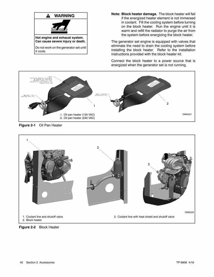
TP-6906 4/1640 Section 2 Accessories
Hot engine and exhaust system.Can cause severe injury or death.
Do not work on the generator set untilit cools.
WARNING Note: Block heater damage. The block heater will failif the energized heater element is not immersedin coolant. Fill the cooling system before turningon the block heater. Run the engine until it iswarm and refill the radiator to purge the air fromthe system before energizing the block heater.
The generator set engine is equipped with valves thateliminate the need to drain the cooling system beforeinstalling the block heater. Refer to the installationinstructions provided with the block heater kit.
Connect the block heater to a power source that isenergized when the generator set is not running.
GM93357
1
1. Oil pan heater (120 VAC)2. Oil pan heater (240 VAC)
2
Figure 2-1 Oil Pan Heater
1
GM90235
1. Coolant line and shutoff valve2. Block heater
3. Coolant line with heat shield and shutoff valve
2
3
Figure 2-2 Block Heater
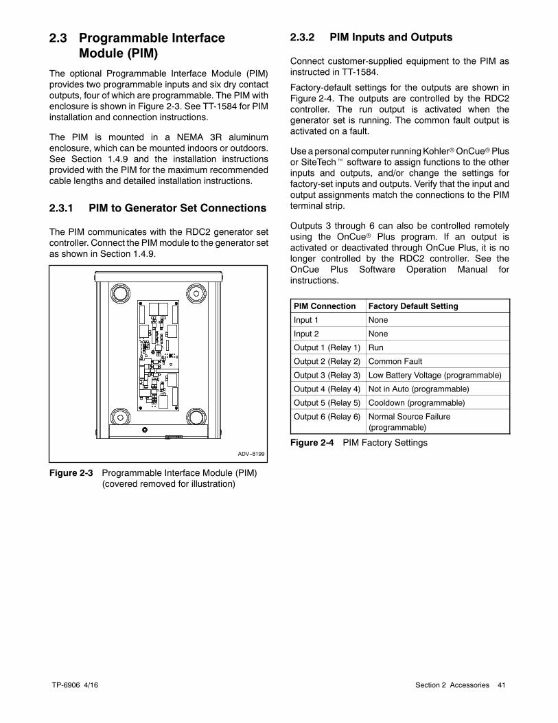
TP-6906 4/16 41Section 2 Accessories
2.3 Programmable InterfaceModule (PIM)
The optional Programmable Interface Module (PIM)provides two programmable inputs and six dry contactoutputs, four of which are programmable. The PIM withenclosure is shown in Figure 2-3. See TT-1584 for PIMinstallation and connection instructions.
The PIM is mounted in a NEMA 3R aluminumenclosure, which can be mounted indoors or outdoors.See Section 1.4.9 and the installation instructionsprovided with the PIM for the maximum recommendedcable lengths and detailed installation instructions.
2.3.1 PIM to Generator Set Connections
The PIM communicates with the RDC2 generator setcontroller. Connect the PIMmodule to the generator setas shown in Section 1.4.9.
ADV--8199
Figure 2-3 Programmable Interface Module (PIM)(covered removed for illustration)
2.3.2 PIM Inputs and Outputs
Connect customer-supplied equipment to the PIM asinstructed in TT-1584.
Factory-default settings for the outputs are shown inFigure 2-4. The outputs are controlled by the RDC2controller. The run output is activated when thegenerator set is running. The common fault output isactivated on a fault.
Useapersonal computer runningKohlerrOnCuerPlusor SiteTecht software to assign functions to the otherinputs and outputs, and/or change the settings forfactory-set inputs and outputs. Verify that the input andoutput assignments match the connections to the PIMterminal strip.
Outputs 3 through 6 can also be controlled remotelyusing the OnCuer Plus program. If an output isactivated or deactivated through OnCue Plus, it is nolonger controlled by the RDC2 controller. See theOnCue Plus Software Operation Manual forinstructions.
PIM Connection Factory Default Setting
Input 1 None
Input 2 None
Output 1 (Relay 1) Run
Output 2 (Relay 2) Common Fault
Output 3 (Relay 3) Low Battery Voltage (programmable)
Output 4 (Relay 4) Not in Auto (programmable)
Output 5 (Relay 5) Cooldown (programmable)
Output 6 (Relay 6) Normal Source Failure(programmable)
Figure 2-4 PIM Factory Settings
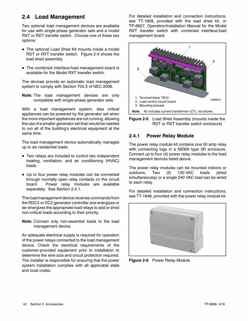
TP-6906 4/1642 Section 2 Accessories
2.4 Load ManagementTwo optional load management devices are availablefor use with single-phase generator sets and a modelRXT or RDT transfer switch. Choose one of these twooptions:
D The optional Load Shed Kit mounts inside a modelRDT or RXT transfer switch. Figure 2-5 shows theload shed assembly.
D The combined interface/ load management board isavailable for the Model RXT transfer switch.
The devices provide an automatic load managementsystem to comply with Section 702.5 of NEC 2008.
Note: The load management devices are onlycompatible with single-phase generator sets.
With a load management system, less criticalappliances can be powered by the generator set whenthemore important appliances are not running, allowingthe use of a smaller generator set thanwould be neededto run all of the building’s electrical equipment at thesame time.
The load management device automatically managesup to six residential loads.
D Two relays are included to control two independentheating, ventilation, and air conditioning (HVAC)loads.
D Up to four power relay modules can be connectedthrough normally open relay contacts on the circuitboard. Power relay modules are availableseparately. See Section 2.4.1.
The loadmanagement device receives commands fromthe RDC2 or DC2 generator controller and energizes orde-energizes the appropriate load relays to add or shednon-critical loads according to their priority.
Note: Connect only non-essential loads to the loadmanagement device.
An adequate electrical supply is required for operationof the power relays connected to the load managementdevice. Check the electrical requirements of thecustomer-provided equipment prior to installation todetermine the wire size and circuit protection required.The installer is responsible for ensuring that the powersystem installation complies with all applicable stateand local codes.
For detailed installation and connection instructions,see TT-1609, provided with the load shed kit, orTP-6807, Operation/Installation Manual for the ModelRXT transfer switch with combined interface/ loadmanagement board.
1. Terminal block TB102. Load control circuit board3. Mounting bracket
Note: Kit includes current transformer (CT), not shown.
2
GM88281
1
3
Figure 2-5 Load Shed Assembly (mounts inside theRDT or RXT transfer switch enclosure)
2.4.1 Power Relay Module
The power relay module kit contains one 50 amp relaywith connecting lugs in a NEMA type 3R enclosure.Connect up to four (4) power relay modules to the loadmanagement devices listed above.
The power relay modules can be mounted indoors oroutdoors. Two (2) 120 VAC loads (shedsimultaneously) or a single 240 VAC load can be wiredto each relay.
For detailed installation and connection instructions,see TT-1646, provided with the power relay module kit.
Figure 2-6 Power Relay Module
TP-6906 4/16 43Section 3 Generator Reconnection
Section 3 Generator Reconnection
3.1 Voltage ReconnectionThe reconnection procedure explains voltagereconnections only. Do not attempt to change thefrequency (e.g. from 60 Hz to 50 Hz) in the field.
The following instructions explain the reconnection of12-lead generator sets. In all cases, follow the NationalElectrical Code (NEC) guidelines.
Reconnect the stator leads of the generator set if adifferent output phase or voltage is desired. Refer to thefollowing procedure and the connection schematics.Follow all safety precautions at the front of this manualand in the text while performing this procedure.
Note: Order voltage reconnection decal 246242 froman authorized service distributor/dealer and affixdecal to generator set after reconnecting to avoltage different than the nameplate.
Accidental starting.Can cause severe injury or death.
Disconnect the battery cables beforeworking on the generator set.Remove the negative (--) lead firstwhen disconnecting the battery.Reconnect the negative (--) lead lastwhen reconnecting the battery.
WARNING
Disabling the generator set. Accidental starting cancause severe injury or death. Before working on thegenerator set or equipment connected to the set, disable thegenerator set as follows: (1) Move the generator set masterswitch to the OFF position. (2) Disconnect the power to thebattery charger. (3) Remove the battery cables, negative (--)lead first. Reconnect the negative (--) lead last whenreconnecting the battery. Follow these precautions to preventstarting of the generator set by an automatic transfer switch,remote start/stop switch, or engine start command from aremote computer.
Hazardous voltage.Can cause severe injury or death.
Operate the generator set only whenall guards and electrical enclosuresare in place.
Moving parts.
WARNING
Grounding electrical equipment. Hazardous voltage cancause severe injury or death. Electrocution is possiblewhenever electricity is present. Ensure you comply with allapplicable codes and standards. Electrically ground thegenerator set, transfer switch, and related equipment andelectrical circuits. Turn off the main circuit breakers of allpower sources before servicing the equipment. Never contactelectrical leads or applianceswhen standing inwater or onwetground because these conditions increase the risk ofelectrocution.
Short circuits. Hazardous voltage/current can causesevere injury or death. Short circuits can cause bodily injuryand/or equipment damage. Do not contact electricalconnections with tools or jewelry while making adjustments orrepairs. Remove all jewelry before servicing the equipment.
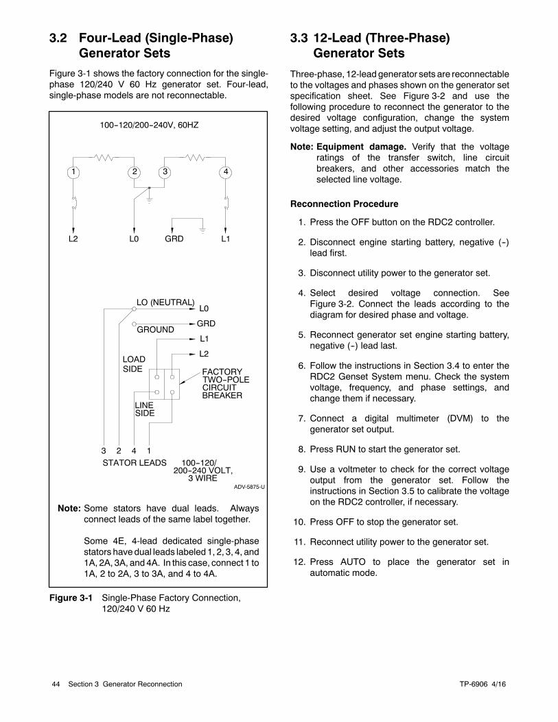
TP-6906 4/1644 Section 3 Generator Reconnection
3.2 Four-Lead (Single-Phase)Generator Sets
Figure 3-1 shows the factory connection for the single-phase 120/240 V 60 Hz generator set. Four-lead,single-phase models are not reconnectable.
ADV-5875-U
Note: Some stators have dual leads. Alwaysconnect leads of the same label together.
Some 4E, 4-lead dedicated single-phasestators havedual leads labeled 1, 2, 3, 4, and1A, 2A, 3A, and 4A. In this case, connect 1 to1A, 2 to 2A, 3 to 3A, and 4 to 4A.
Figure 3-1 Single-Phase Factory Connection,120/240 V 60 Hz
3.3 12-Lead (Three-Phase)Generator Sets
Three-phase, 12-leadgenerator sets are reconnectableto the voltages and phases shown on the generator setspecification sheet. See Figure 3-2 and use thefollowing procedure to reconnect the generator to thedesired voltage configuration, change the systemvoltage setting, and adjust the output voltage.
Note: Equipment damage. Verify that the voltageratings of the transfer switch, line circuitbreakers, and other accessories match theselected line voltage.
Reconnection Procedure
1. Press the OFF button on the RDC2 controller.
2. Disconnect engine starting battery, negative (--)lead first.
3. Disconnect utility power to the generator set.
4. Select desired voltage connection. SeeFigure 3-2. Connect the leads according to thediagram for desired phase and voltage.
5. Reconnect generator set engine starting battery,negative (--) lead last.
6. Follow the instructions in Section 3.4 to enter theRDC2 Genset System menu. Check the systemvoltage, frequency, and phase settings, andchange them if necessary.
7. Connect a digital multimeter (DVM) to thegenerator set output.
8. Press RUN to start the generator set.
9. Use a voltmeter to check for the correct voltageoutput from the generator set. Follow theinstructions in Section 3.5 to calibrate the voltageon the RDC2 controller, if necessary.
10. Press OFF to stop the generator set.
11. Reconnect utility power to the generator set.
12. Press AUTO to place the generator set inautomatic mode.
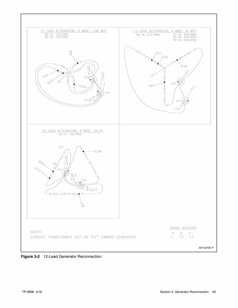
TP-6906 4/16 45Section 3 Generator Reconnection
ADV-5875E-P
Figure 3-2 12-Lead Generator Reconnection
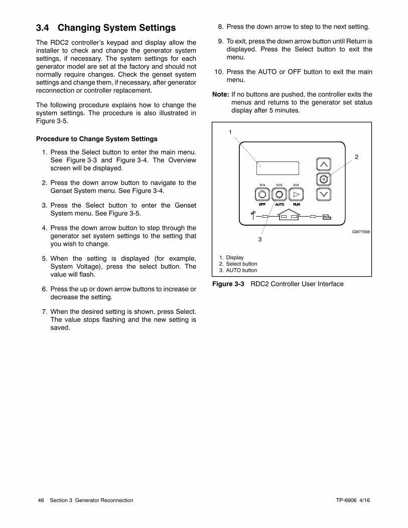
TP-6906 4/1646 Section 3 Generator Reconnection
3.4 Changing System SettingsThe RDC2 controller’s keypad and display allow theinstaller to check and change the generator systemsettings, if necessary. The system settings for eachgenerator model are set at the factory and should notnormally require changes. Check the genset systemsettings and change them, if necessary, after generatorreconnection or controller replacement.
The following procedure explains how to change thesystem settings. The procedure is also illustrated inFigure 3-5.
Procedure to Change System Settings
1. Press the Select button to enter the main menu.See Figure 3-3 and Figure 3-4. The Overviewscreen will be displayed.
2. Press the down arrow button to navigate to theGenset System menu. See Figure 3-4.
3. Press the Select button to enter the GensetSystem menu. See Figure 3-5.
4. Press the down arrow button to step through thegenerator set system settings to the setting thatyou wish to change.
5. When the setting is displayed (for example,System Voltage), press the select button. Thevalue will flash.
6. Press the up or down arrow buttons to increase ordecrease the setting.
7. When the desired setting is shown, press Select.The value stops flashing and the new setting issaved.
8. Press the down arrow to step to the next setting.
9. To exit, press the down arrow button until Return isdisplayed. Press the Select button to exit themenu.
10. Press the AUTO or OFF button to exit the mainmenu.
Note: If no buttons are pushed, the controller exits themenus and returns to the generator set statusdisplay after 5 minutes.
GM77569
2
1. Display2. Select button3. AUTO button
1
3
Figure 3-3 RDC2 Controller User Interface
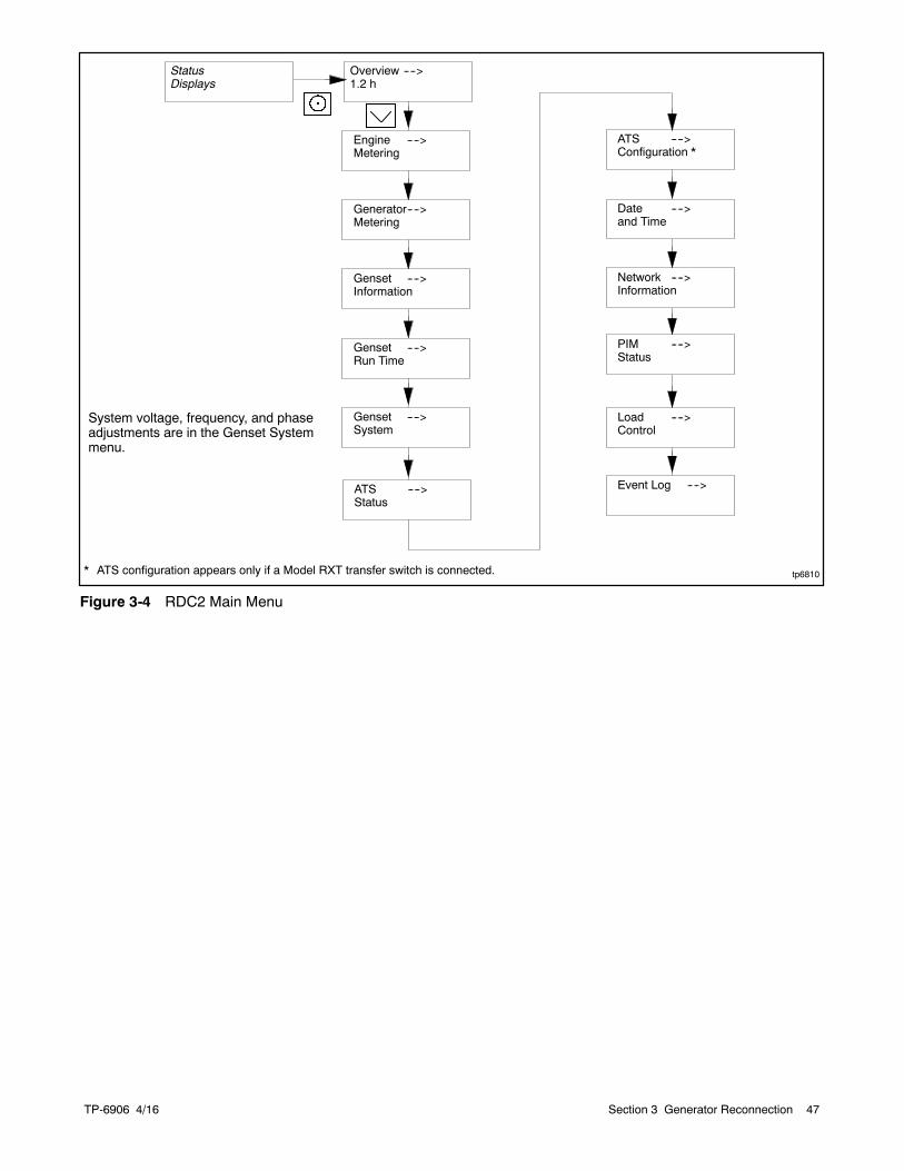
TP-6906 4/16 47Section 3 Generator Reconnection
Overview ---->1.2 h
Engine ---->Metering
tp6810
Generator---->Metering
Genset ---->Information
Genset ---->Run Time
Date ---->and Time
ATS ---->Configuration *
Genset ---->System
Event Log ---->
Load ---->Control
PIM ---->Status
Network ---->Information
StatusDisplays
ATS ---->Status
* ATS configuration appears only if a Model RXT transfer switch is connected.
System voltage, frequency, and phaseadjustments are in the Genset Systemmenu.
Figure 3-4 RDC2 Main Menu
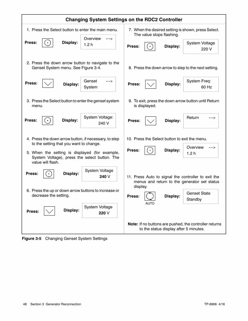
TP-6906 4/1648 Section 3 Generator Reconnection
1. Press the Select button to enter the main menu.
2. Press the down arrow button to navigate to theGenset System menu. See Figure 3-4.
3. Press theSelect button to enter the genset systemmenu.
4. Press the down arrow button, if necessary, to stepto the setting that you want to change.
5. When the setting is displayed (for example,System Voltage), press the select button. Thevalue will flash.
6. Press the up or down arrow buttons to increase ordecrease the setting.
Press:
Changing System Settings on the RDC2 Controller
Press: Display:Overview ---->1.2 h
Display:
Press: Display:
Genset ---->System
System Voltage:240 V
7. When the desired setting is shown, press Select.The value stops flashing.
8. Press the down arrow to step to the next setting.
9. To exit, press the down arrow button until Returnis displayed.
10. Press the Select button to exit the menu.
11. Press Auto to signal the controller to exit themenus and return to the generator set statusdisplay.
Press: Display:System Voltage
240 V
Press: Display:
Press: Display:System Freq:
60 Hz
Press: Display:Return ---->
Press: Display:
System Voltage220 V
Overview ---->1.2 h
AUTO
Press: Display:Genset StateStandby
Note: If no buttons are pushed, the controller returnsto the status display after 5 minutes.
Press: Display:System Voltage
220 V
Figure 3-5 Changing Genset System Settings
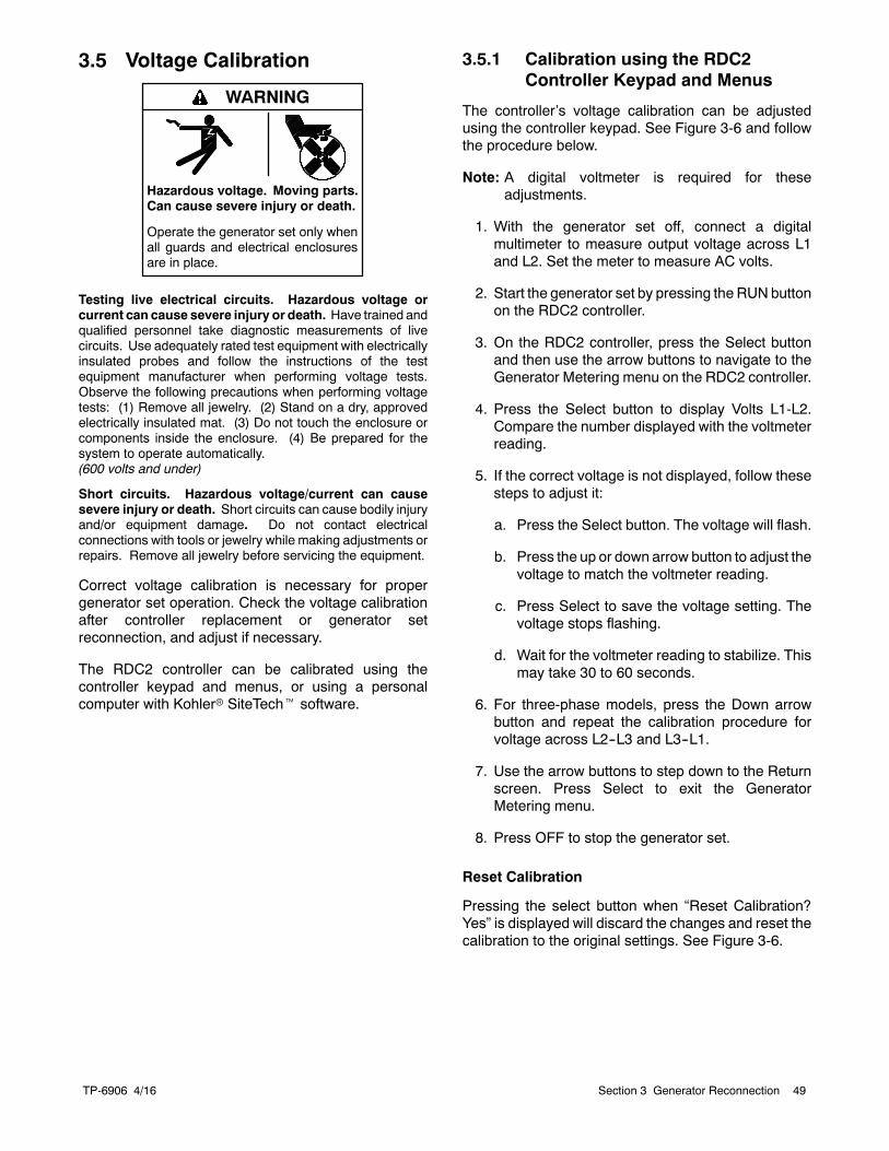
TP-6906 4/16 49Section 3 Generator Reconnection
3.5 Voltage Calibration
Hazardous voltage.Can cause severe injury or death.
Operate the generator set only whenall guards and electrical enclosuresare in place.
Moving parts.
WARNING
Testing live electrical circuits. Hazardous voltage orcurrent can cause severe injury or death. Have trained andqualified personnel take diagnostic measurements of livecircuits. Use adequately rated test equipment with electricallyinsulated probes and follow the instructions of the testequipment manufacturer when performing voltage tests.Observe the following precautions when performing voltagetests: (1) Remove all jewelry. (2) Stand on a dry, approvedelectrically insulated mat. (3) Do not touch the enclosure orcomponents inside the enclosure. (4) Be prepared for thesystem to operate automatically.(600 volts and under)
Short circuits. Hazardous voltage/current can causesevere injury or death. Short circuits can cause bodily injuryand/or equipment damage. Do not contact electricalconnections with tools or jewelry while making adjustments orrepairs. Remove all jewelry before servicing the equipment.
Correct voltage calibration is necessary for propergenerator set operation. Check the voltage calibrationafter controller replacement or generator setreconnection, and adjust if necessary.
The RDC2 controller can be calibrated using thecontroller keypad and menus, or using a personalcomputer with Kohlerr SiteTecht software.
3.5.1 Calibration using the RDC2Controller Keypad and Menus
The controller’s voltage calibration can be adjustedusing the controller keypad. See Figure 3-6 and followthe procedure below.
Note: A digital voltmeter is required for theseadjustments.
1. With the generator set off, connect a digitalmultimeter to measure output voltage across L1and L2. Set the meter to measure AC volts.
2. Start the generator set by pressing the RUN buttonon the RDC2 controller.
3. On the RDC2 controller, press the Select buttonand then use the arrow buttons to navigate to theGenerator Metering menu on the RDC2 controller.
4. Press the Select button to display Volts L1-L2.Compare the number displayed with the voltmeterreading.
5. If the correct voltage is not displayed, follow thesesteps to adjust it:
a. Press the Select button. The voltage will flash.
b. Press the up or down arrow button to adjust thevoltage to match the voltmeter reading.
c. Press Select to save the voltage setting. Thevoltage stops flashing.
d. Wait for the voltmeter reading to stabilize. Thismay take 30 to 60 seconds.
6. For three-phase models, press the Down arrowbutton and repeat the calibration procedure forvoltage across L2--L3 and L3--L1.
7. Use the arrow buttons to step down to the Returnscreen. Press Select to exit the GeneratorMetering menu.
8. Press OFF to stop the generator set.
Reset Calibration
Pressing the select button when “Reset Calibration?Yes” is displayed will discard the changes and reset thecalibration to the original settings. See Figure 3-6.
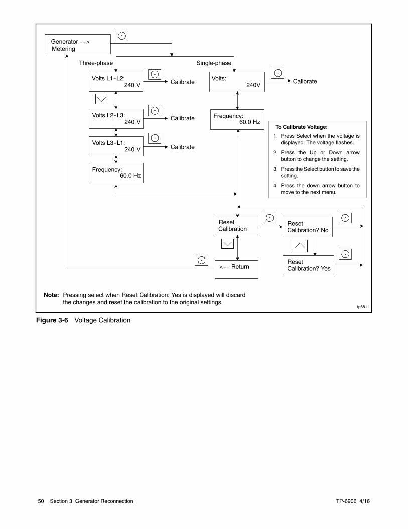
TP-6906 4/1650 Section 3 Generator Reconnection
Volts L1--L2:240 V
Volts L2--L3:240 V
Volts L3--L1:240 V
Generator ---->Metering
ResetCalibration
<---- Return
ResetCalibration? No
Volts:240V
Three-phase Single-phase
tp6811
ResetCalibration? Yes
Frequency:60.0 Hz
Frequency:60.0 Hz
1. Press Select when the voltage isdisplayed. The voltage flashes.
2. Press the Up or Down arrowbutton to change the setting.
3. Press theSelect button to save thesetting.
4. Press the down arrow button tomove to the next menu.
Calibrate
Calibrate
Calibrate
Calibrate
Note: Pressing select when Reset Calibration: Yes is displayed will discardthe changes and reset the calibration to the original settings.
To Calibrate Voltage:
Figure 3-6 Voltage Calibration
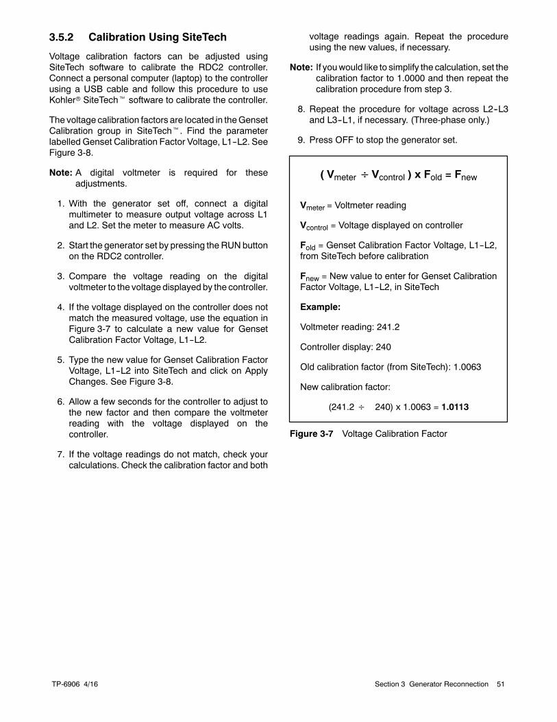
TP-6906 4/16 51Section 3 Generator Reconnection
3.5.2 Calibration Using SiteTech
Voltage calibration factors can be adjusted usingSiteTech software to calibrate the RDC2 controller.Connect a personal computer (laptop) to the controllerusing a USB cable and follow this procedure to useKohlerr SiteTecht software to calibrate the controller.
The voltage calibration factors are located in theGensetCalibration group in SiteTecht. Find the parameterlabelled Genset Calibration Factor Voltage, L1--L2. SeeFigure 3-8.
Note: A digital voltmeter is required for theseadjustments.
1. With the generator set off, connect a digitalmultimeter to measure output voltage across L1and L2. Set the meter to measure AC volts.
2. Start the generator set by pressing the RUN buttonon the RDC2 controller.
3. Compare the voltage reading on the digitalvoltmeter to the voltage displayed by the controller.
4. If the voltage displayed on the controller does notmatch the measured voltage, use the equation inFigure 3-7 to calculate a new value for GensetCalibration Factor Voltage, L1--L2.
5. Type the new value for Genset Calibration FactorVoltage, L1--L2 into SiteTech and click on ApplyChanges. See Figure 3-8.
6. Allow a few seconds for the controller to adjust tothe new factor and then compare the voltmeterreading with the voltage displayed on thecontroller.
7. If the voltage readings do not match, check yourcalculations. Check the calibration factor and both
voltage readings again. Repeat the procedureusing the new values, if necessary.
Note: If youwould like to simplify the calculation, set thecalibration factor to 1.0000 and then repeat thecalibration procedure from step 3.
8. Repeat the procedure for voltage across L2--L3and L3--L1, if necessary. (Three-phase only.)
9. Press OFF to stop the generator set.
( Vmeter÷Vcontrol ) x Fold = Fnew
Vmeter = Voltmeter reading
Vcontrol = Voltage displayed on controller
Fold = Genset Calibration Factor Voltage, L1--L2,from SiteTech before calibration
Fnew = New value to enter for Genset CalibrationFactor Voltage, L1--L2, in SiteTech
Example:
Voltmeter reading: 241.2
Controller display: 240
Old calibration factor (from SiteTech): 1.0063
New calibration factor:
(241.2÷ 240) x 1.0063 = 1.0113
Figure 3-7 Voltage Calibration Factor
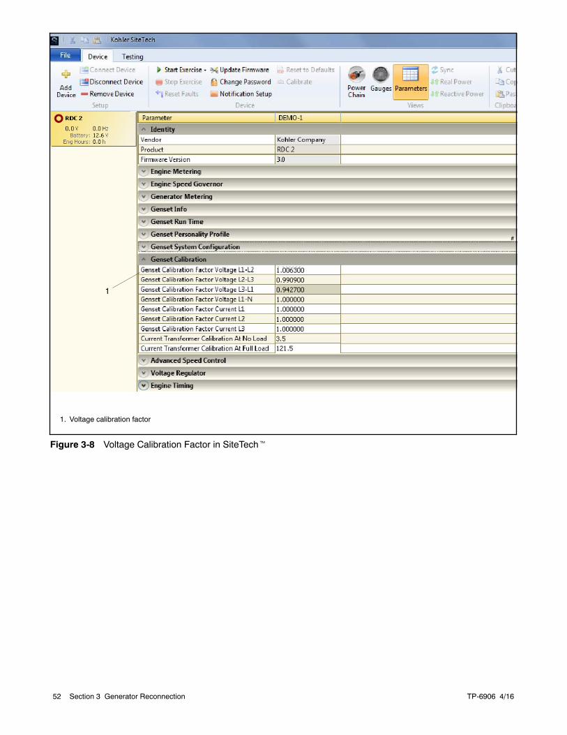
TP-6906 4/1652 Section 3 Generator Reconnection
#
1. Voltage calibration factor
1
Figure 3-8 Voltage Calibration Factor in SiteTecht
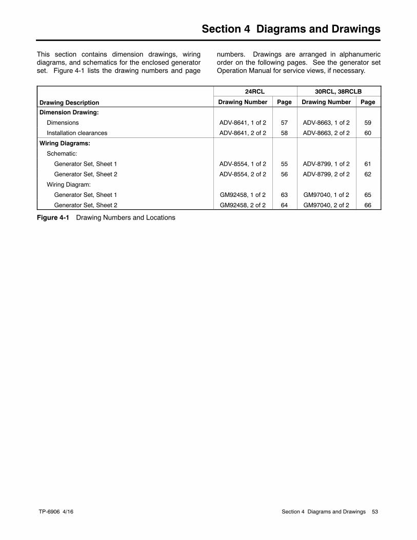
TP-6906 4/16 53Section 4 Diagrams and Drawings
Section 4 Diagrams and Drawings
This section contains dimension drawings, wiringdiagrams, and schematics for the enclosed generatorset. Figure 4-1 lists the drawing numbers and page
numbers. Drawings are arranged in alphanumericorder on the following pages. See the generator setOperation Manual for service views, if necessary.
Drawing Description
24RCL 30RCL, 38RCLB
Drawing Number Page Drawing Number Page
Dimension Drawing:
Dimensions ADV-8641, 1 of 2 57 ADV-8663, 1 of 2 59
Installation clearances ADV-8641, 2 of 2 58 ADV-8663, 2 of 2 60
Wiring Diagrams:
Schematic:
Generator Set, Sheet 1 ADV-8554, 1 of 2 55 ADV-8799, 1 of 2 61
Generator Set, Sheet 2 ADV-8554, 2 of 2 56 ADV-8799, 2 of 2 62
Wiring Diagram:
Generator Set, Sheet 1 GM92458, 1 of 2 63 GM97040, 1 of 2 65
Generator Set, Sheet 2 GM92458, 2 of 2 64 GM97040, 2 of 2 66
Figure 4-1 Drawing Numbers and Locations

TP-6906 4/1654
Notes
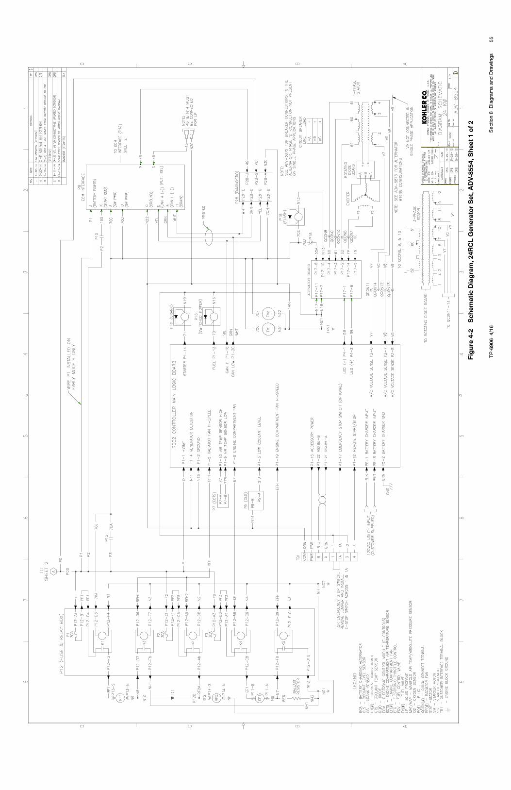
TP-69064/16
55Section8Diagram
sandDrawings
Figure
4-2
Schem
aticDiagram,24R
CLGeneratorSet,A
DV-8554,Sheet1of2
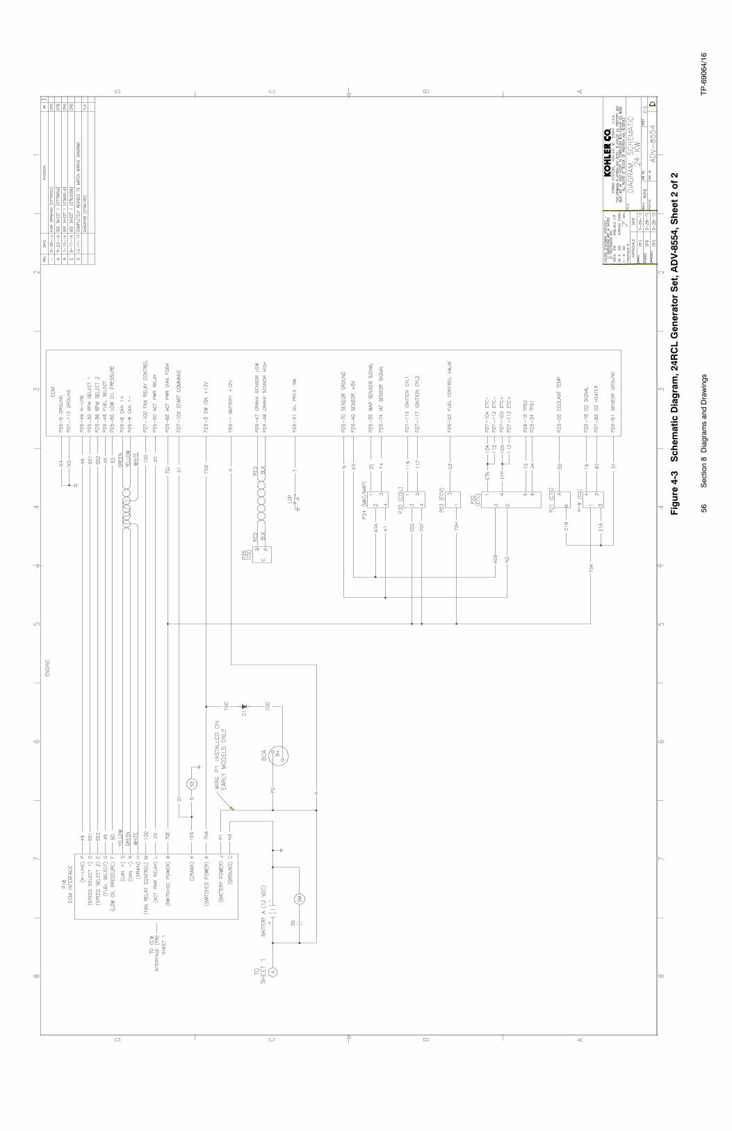
TP-69064/16
56Section8Diagram
sandDrawings
Figure
4-3
Schem
aticDiagram,24R
CLGeneratorSet,A
DV-8554,Sheet2of2
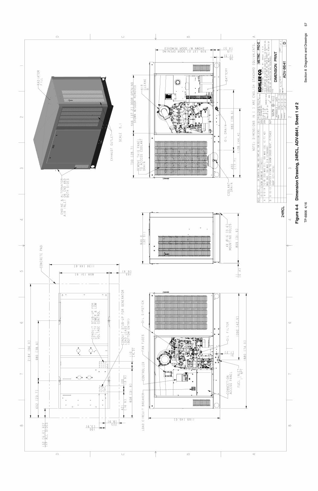
TP-69064/16
57Section8Diagram
sandDrawings
Figure
4-4
DimensionDrawing,24R
CL,A
DV-8641,Sheet1of2
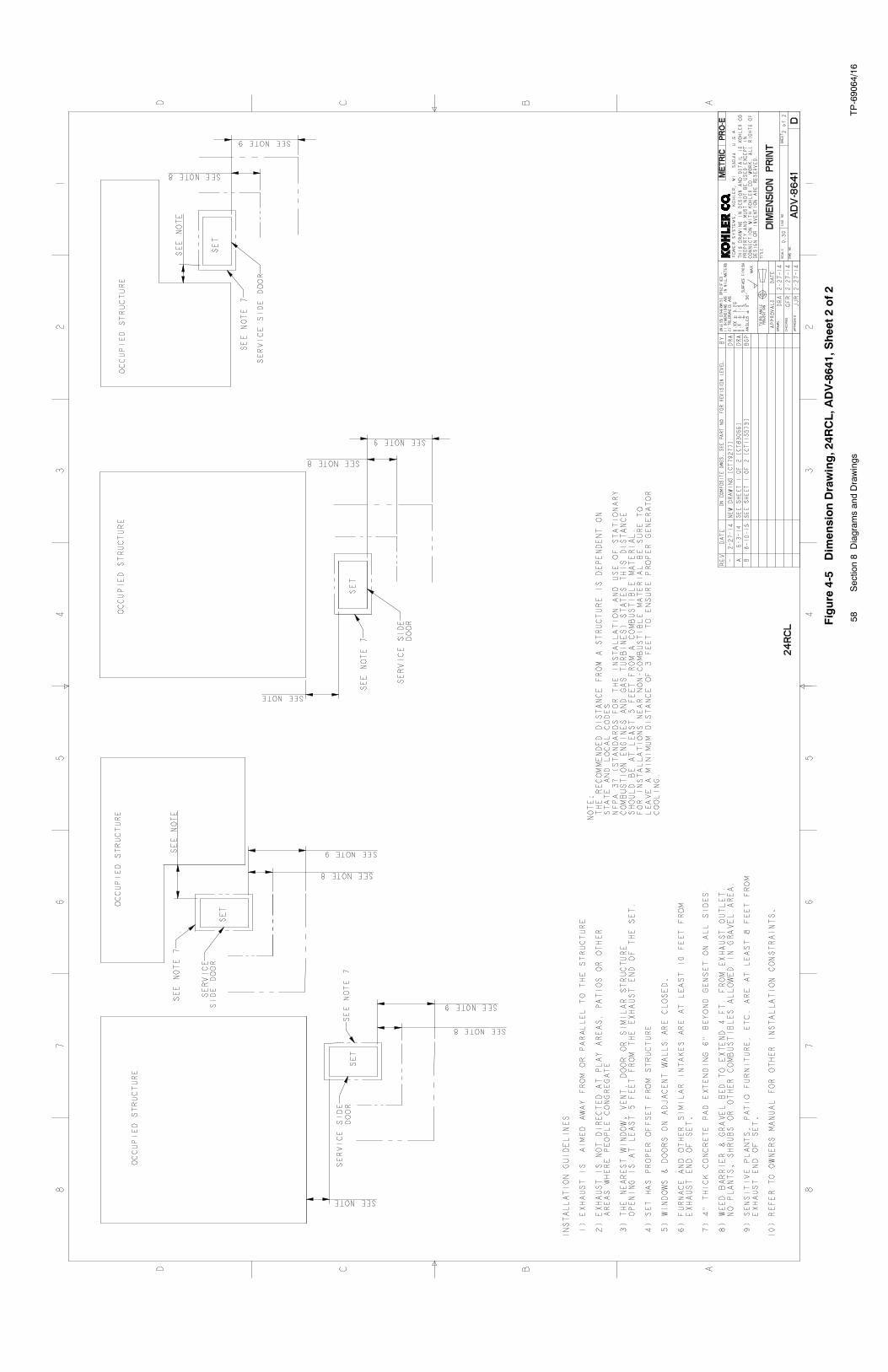
TP-69064/16
58Section8Diagram
sandDrawings
Figure
4-5
DimensionDrawing,24R
CL,A
DV-8641,Sheet2of2
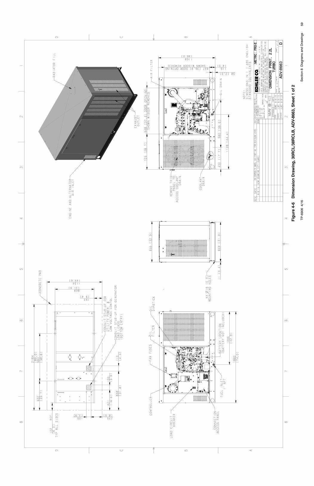
TP-69064/16
59Section8Diagram
sandDrawings
Figure
4-6
DimensionDrawing,30R
CL/38R
CLB,A
DV-8663,Sheet1of2
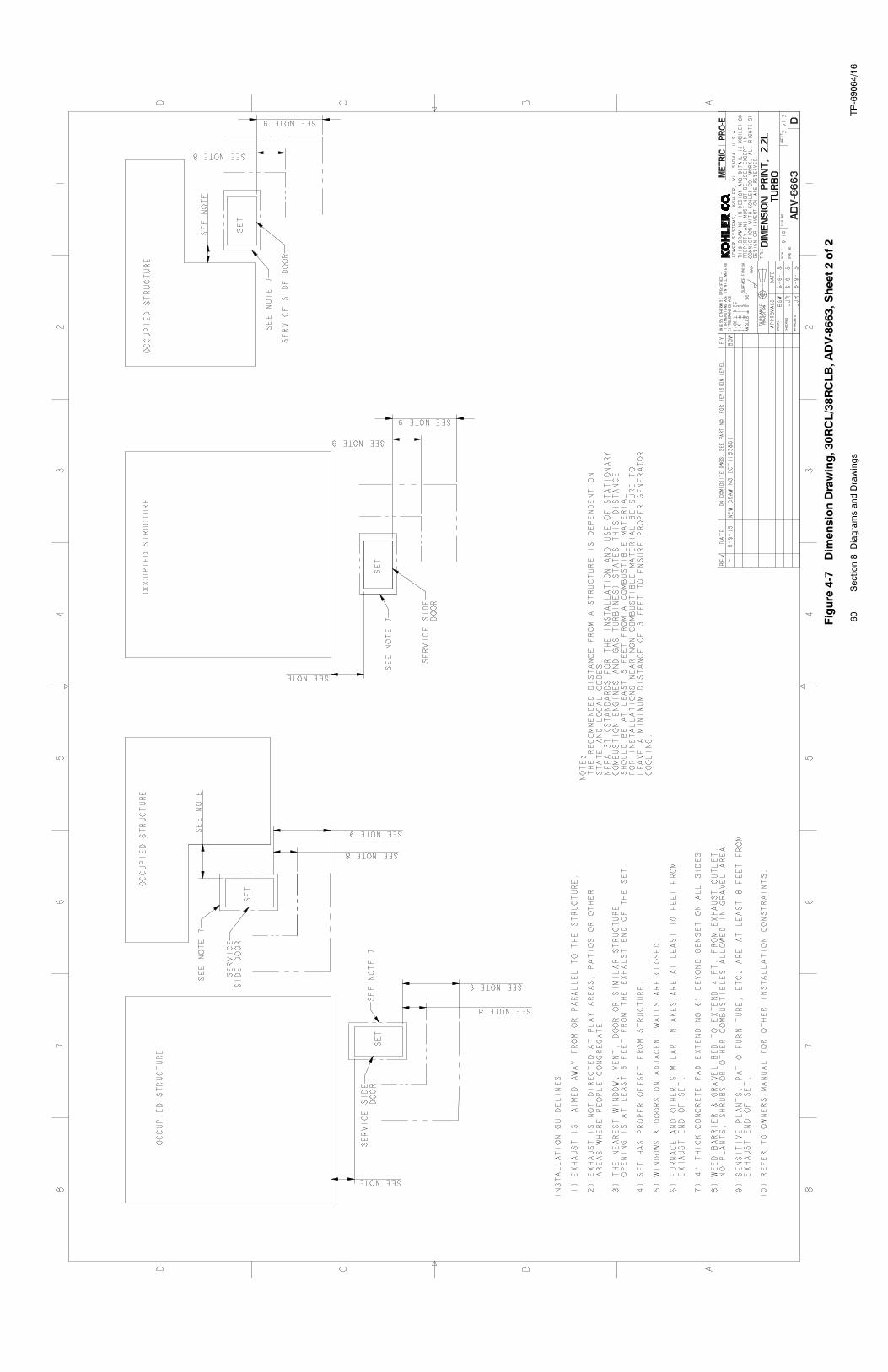
TP-69064/16
60Section8Diagram
sandDrawings
Figure
4-7
DimensionDrawing,30R
CL/38R
CLB,A
DV-8663,Sheet2of2
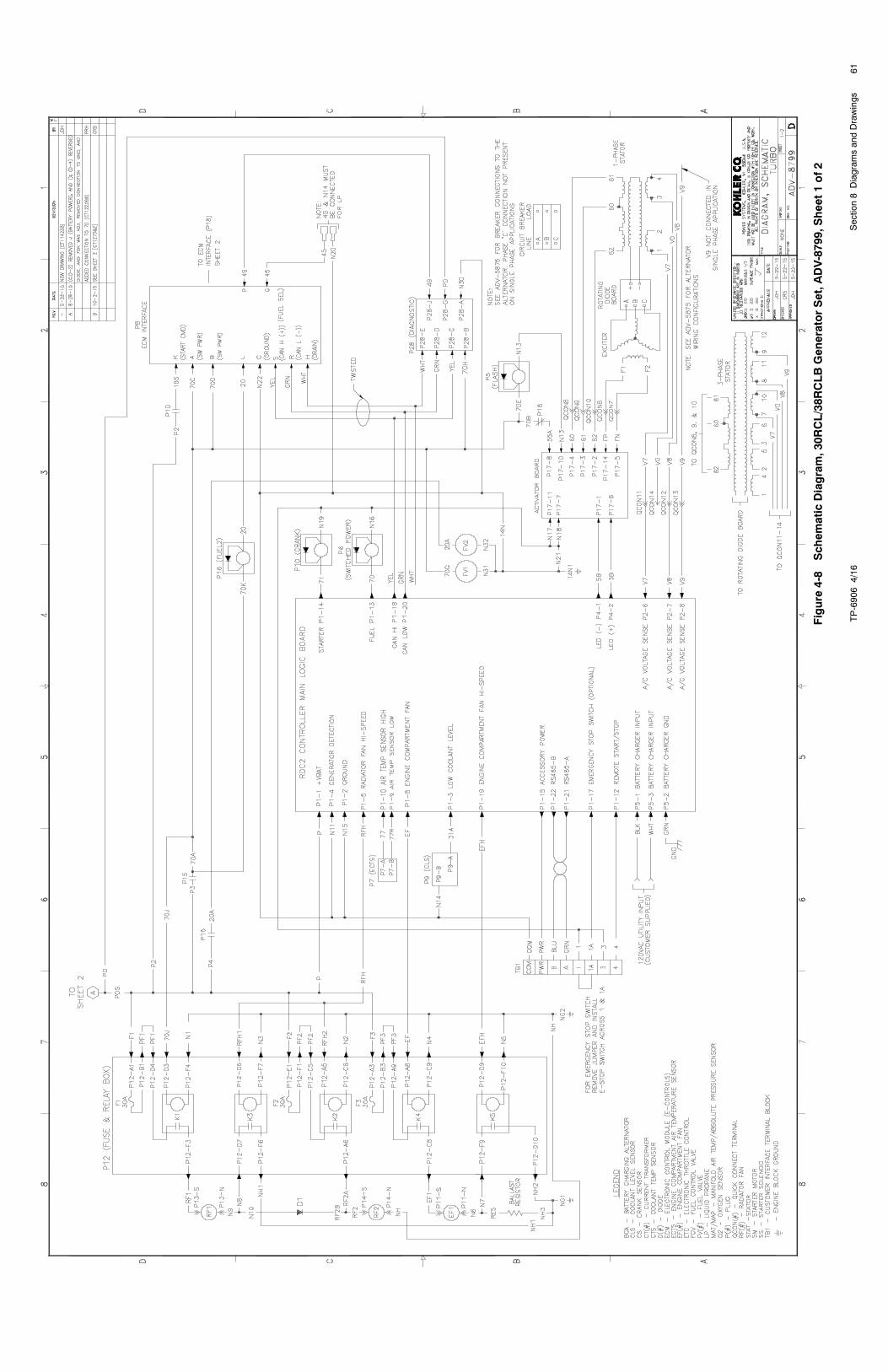
TP-69064/16
61Section8Diagram
sandDrawings
Figure
4-8
Schem
aticDiagram,30R
CL/38R
CLBGeneratorSet,A
DV-8799,Sheet1of2
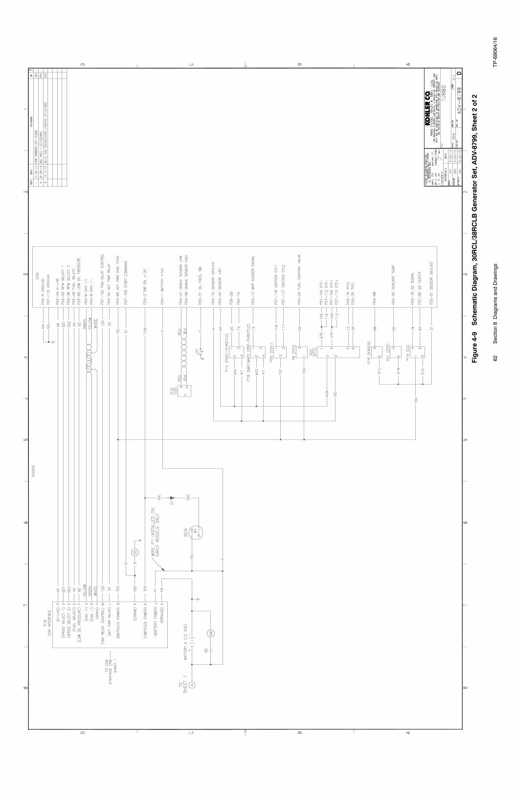
TP-69064/16
62Section8Diagram
sandDrawings
Figure
4-9
Schem
aticDiagram,30R
CL/38R
CLBGeneratorSet,A
DV-8799,Sheet2of2
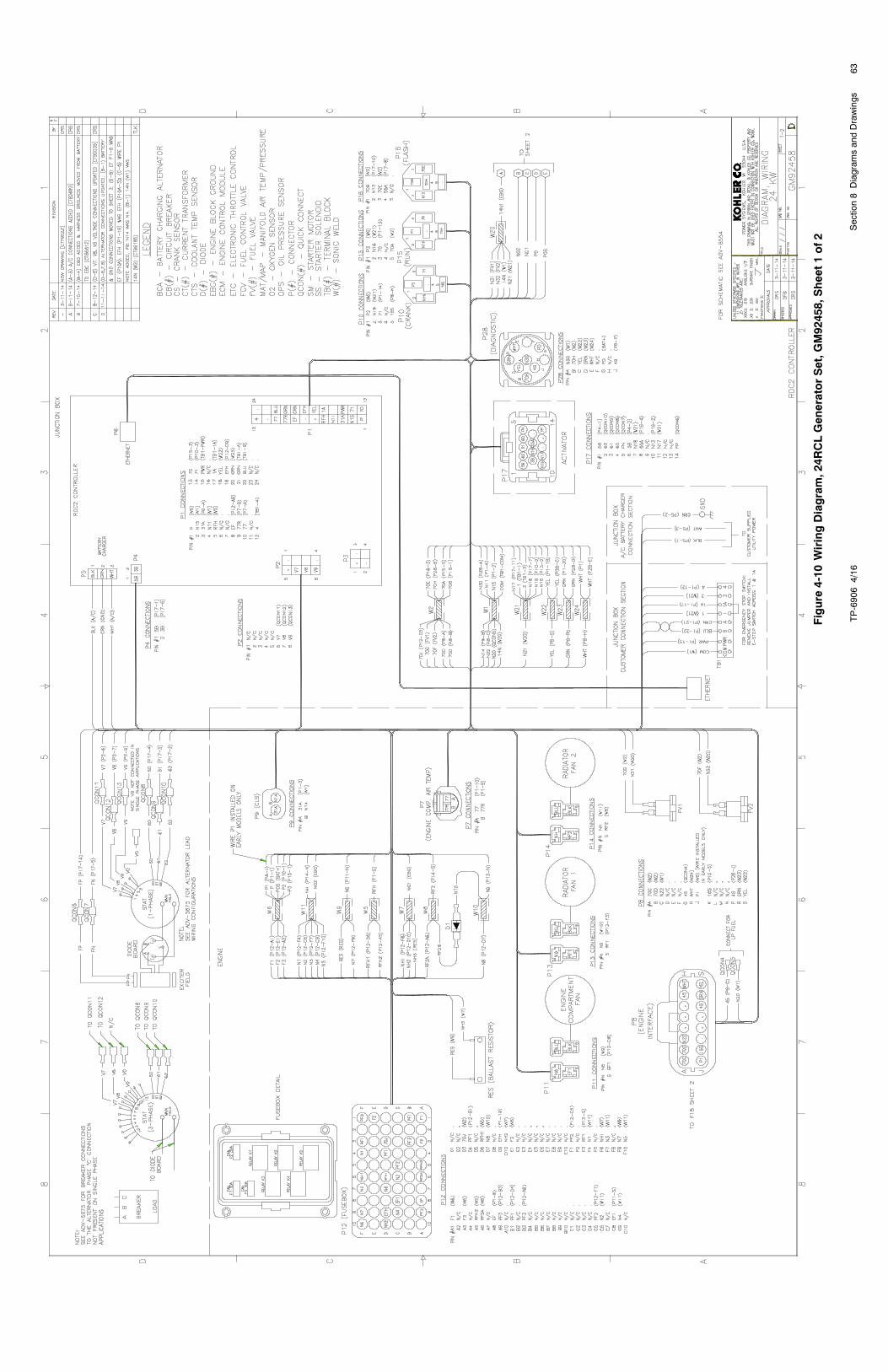
TP-69064/16
63Section8Diagram
sandDrawings
Figure
4-10
WiringDiagram,24R
CLGeneratorSet,G
M92458,Sheet1of2
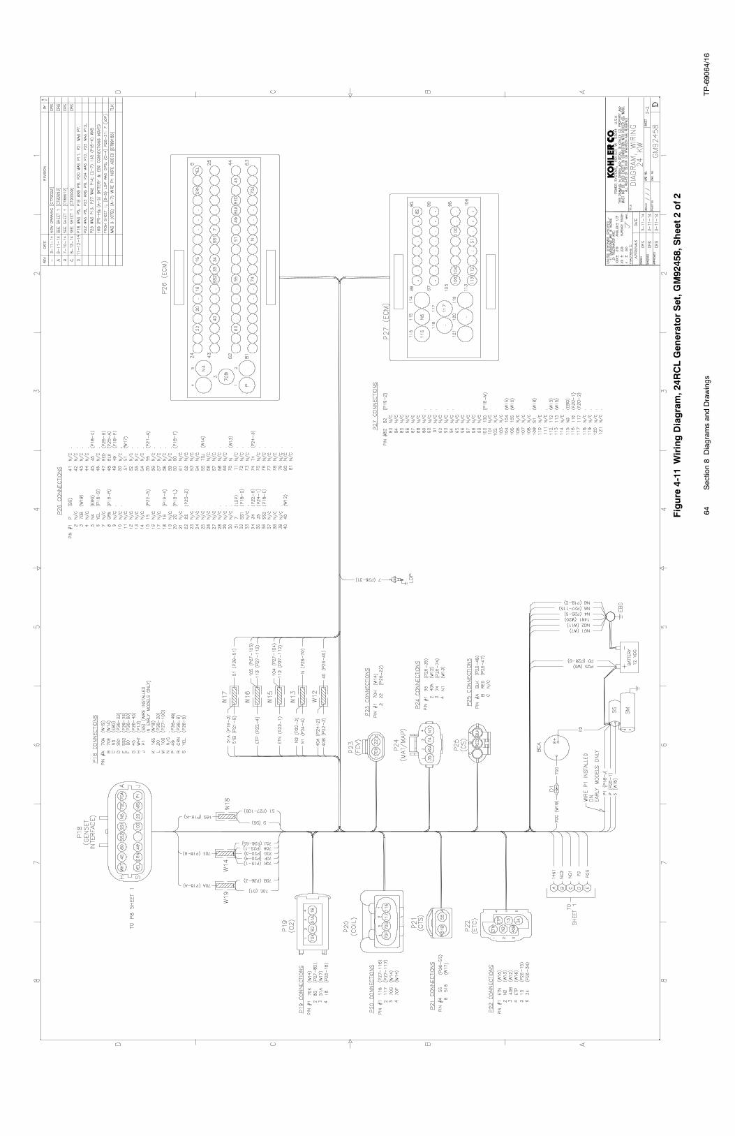
TP-69064/16
64Section8Diagram
sandDrawings
Figure
4-11
WiringDiagram,24R
CLGeneratorSet,G
M92458,Sheet2of2
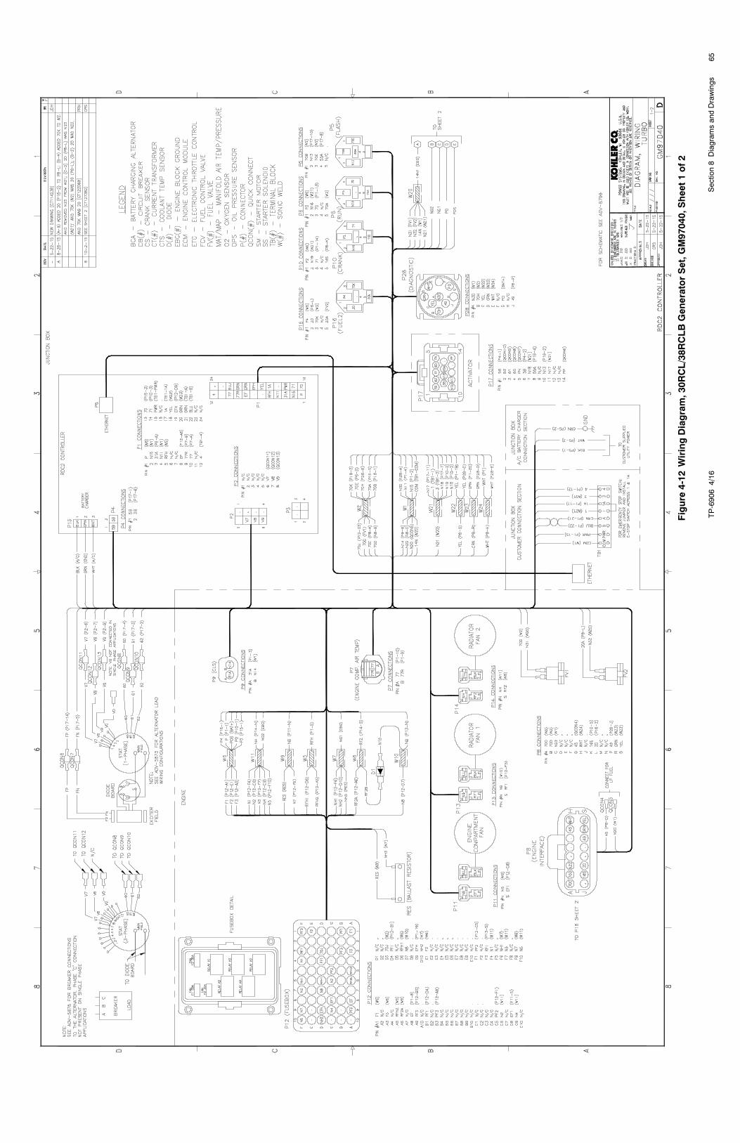
TP-69064/16
65Section8Diagram
sandDrawings
Figure
4-12
WiringDiagram,30R
CL/38R
CLBGeneratorSet,G
M97040,Sheet1of2
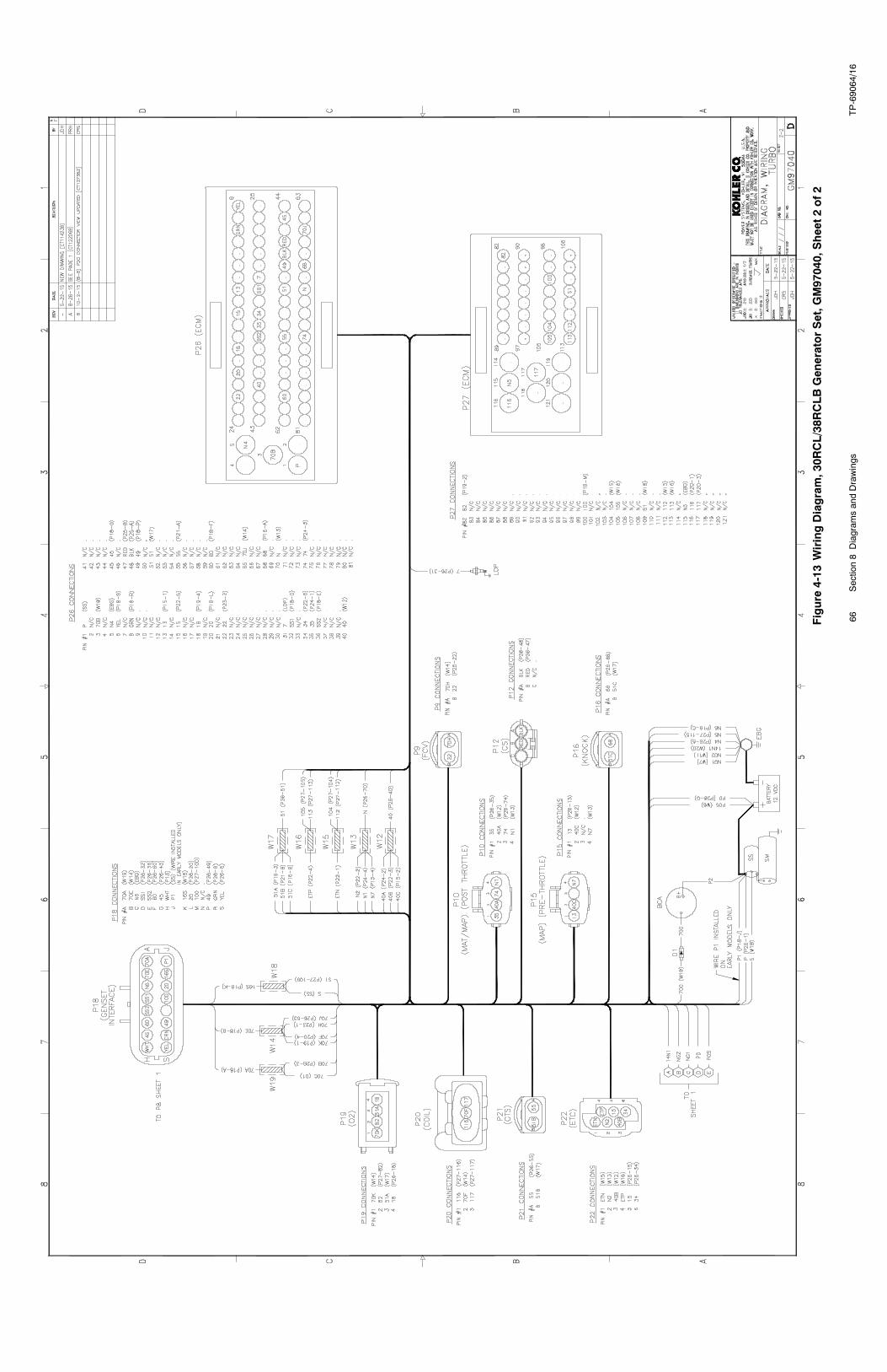
TP-69064/16
66Section8Diagram
sandDrawings
Figure
4-13
WiringDiagram,30R
CL/38R
CLBGeneratorSet,G
M97040,Sheet2of2
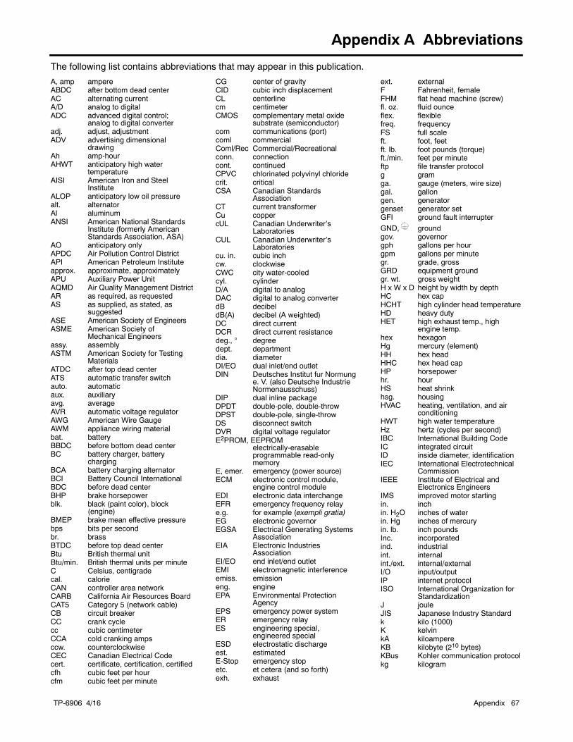
TP-6906 4/16 Appendix 67
Appendix A Abbreviations
The following list contains abbreviations that may appear in this publication.
A, amp ampereABDC after bottom dead centerAC alternating currentA/D analog to digitalADC advanced digital control;
analog to digital converteradj. adjust, adjustmentADV advertising dimensional
drawingAh amp-hourAHWT anticipatory high water
temperatureAISI American Iron and Steel
InstituteALOP anticipatory low oil pressurealt. alternatorAl aluminumANSI American National Standards
Institute (formerly AmericanStandards Association, ASA)
AO anticipatory onlyAPDC Air Pollution Control DistrictAPI American Petroleum Instituteapprox. approximate, approximatelyAPU Auxiliary Power UnitAQMD Air Quality Management DistrictAR as required, as requestedAS as supplied, as stated, as
suggestedASE American Society of EngineersASME American Society of
Mechanical Engineersassy. assemblyASTM American Society for Testing
MaterialsATDC after top dead centerATS automatic transfer switchauto. automaticaux. auxiliaryavg. averageAVR automatic voltage regulatorAWG American Wire GaugeAWM appliance wiring materialbat. batteryBBDC before bottom dead centerBC battery charger, battery
chargingBCA battery charging alternatorBCI Battery Council InternationalBDC before dead centerBHP brake horsepowerblk. black (paint color), block
(engine)BMEP brake mean effective pressurebps bits per secondbr. brassBTDC before top dead centerBtu British thermal unitBtu/min. British thermal units per minuteC Celsius, centigradecal. calorieCAN controller area networkCARB California Air Resources BoardCAT5 Category 5 (network cable)CB circuit breakerCC crank cyclecc cubic centimeterCCA cold cranking ampsccw. counterclockwiseCEC Canadian Electrical Codecert. certificate, certification, certifiedcfh cubic feet per hourcfm cubic feet per minute
CG center of gravityCID cubic inch displacementCL centerlinecm centimeterCMOS complementary metal oxide
substrate (semiconductor)com communications (port)coml commercialComl/Rec Commercial/Recreationalconn. connectioncont. continuedCPVC chlorinated polyvinyl chloridecrit. criticalCSA Canadian Standards
AssociationCT current transformerCu coppercUL Canadian Underwriter’s
LaboratoriesCUL Canadian Underwriter’s
Laboratoriescu. in. cubic inchcw. clockwiseCWC city water-cooledcyl. cylinderD/A digital to analogDAC digital to analog converterdB decibeldB(A) decibel (A weighted)DC direct currentDCR direct current resistancedeg., degreedept. departmentdia. diameterDI/EO dual inlet/end outletDIN Deutsches Institut fur Normung
e. V. (also Deutsche IndustrieNormenausschuss)
DIP dual inline packageDPDT double-pole, double-throwDPST double-pole, single-throwDS disconnect switchDVR digital voltage regulatorE2PROM, EEPROM
electrically-erasableprogrammable read-onlymemory
E, emer. emergency (power source)ECM electronic control module,
engine control moduleEDI electronic data interchangeEFR emergency frequency relaye.g. for example (exempli gratia)EG electronic governorEGSA Electrical Generating Systems
AssociationEIA Electronic Industries
AssociationEI/EO end inlet/end outletEMI electromagnetic interferenceemiss. emissioneng. engineEPA Environmental Protection
AgencyEPS emergency power systemER emergency relayES engineering special,
engineered specialESD electrostatic dischargeest. estimatedE-Stop emergency stopetc. et cetera (and so forth)exh. exhaust
ext. externalF Fahrenheit, femaleFHM flat head machine (screw)fl. oz. fluid ounceflex. flexiblefreq. frequencyFS full scaleft. foot, feetft. lb. foot pounds (torque)ft./min. feet per minuteftp file transfer protocolg gramga. gauge (meters, wire size)gal. gallongen. generatorgenset generator setGFI ground fault interrupterGND, groundgov. governorgph gallons per hourgpm gallons per minutegr. grade, grossGRD equipment groundgr. wt. gross weightH x W x D height by width by depthHC hex capHCHT high cylinder head temperatureHD heavy dutyHET high exhaust temp., high
engine temp.hex hexagonHg mercury (element)HH hex headHHC hex head capHP horsepowerhr. hourHS heat shrinkhsg. housingHVAC heating, ventilation, and air
conditioningHWT high water temperatureHz hertz (cycles per second)IBC International Building CodeIC integrated circuitID inside diameter, identificationIEC International Electrotechnical
CommissionIEEE Institute of Electrical and
Electronics EngineersIMS improved motor startingin. inchin. H2O inches of waterin. Hg inches of mercuryin. lb. inch poundsInc. incorporatedind. industrialint. internalint./ext. internal/externalI/O input/outputIP internet protocolISO International Organization for
StandardizationJ jouleJIS Japanese Industry Standardk kilo (1000)K kelvinkA kiloampereKB kilobyte (210 bytes)KBus Kohler communication protocolkg kilogram
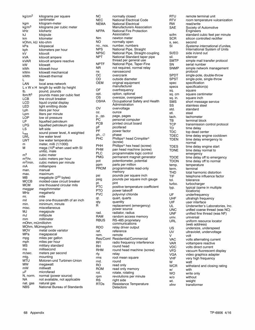
TP-6906 4/1668 Appendix
kg/cm2 kilograms per squarecentimeter
kgm kilogram-meterkg/m3 kilograms per cubic meterkHz kilohertzkJ kilojoulekm kilometerkOhm, k kilo-ohmkPa kilopascalkph kilometers per hourkV kilovoltkVA kilovolt amperekVAR kilovolt ampere reactivekW kilowattkWh kilowatt-hourkWm kilowatt mechanicalkWth kilowatt-thermalL literLAN local area networkL x W x H length by width by heightlb. pound, poundslbm/ft3 pounds mass per cubic feetLCB line circuit breakerLCD liquid crystal displayLED light emitting diodeLph liters per hourLpm liters per minuteLOP low oil pressureLP liquefied petroleumLPG liquefied petroleum gasLS left sideLwa sound power level, A weightedLWL low water levelLWT low water temperaturem meter, milli (1/1000)M mega (106 when used with SI
units), malem3 cubic meterm3/hr. cubic meters per hourm3/min. cubic meters per minutemA milliampereman. manualmax. maximumMB megabyte (220 bytes)MCCB molded-case circuit breakerMCM one thousand circular milsmeggar megohmmeterMHz megahertzmi. milemil one one-thousandth of an inchmin. minimum, minutemisc. miscellaneousMJ megajoulemJ millijoulemm millimetermOhm, mmilliohmMOhm, MmegohmMOV metal oxide varistorMPa megapascalmpg miles per gallonmph miles per hourMS military standardms millisecondm/sec. meters per secondmtg. mountingMTU Motoren-und Turbinen-UnionMW megawattmW milliwattF microfaradN, norm. normal (power source)NA not available, not applicablenat. gas natural gasNBS National Bureau of Standards
NC normally closedNEC National Electrical CodeNEMA National Electrical
Manufacturers AssociationNFPA National Fire Protection
AssociationNm newton meterNO normally openno., nos. number, numbersNPS National Pipe, StraightNPSC National Pipe, Straight-couplingNPT National Standard taper pipe
thread per general useNPTF National Pipe, Taper-FineNR not required, normal relayns nanosecondOC overcrankOD outside diameterOEM original equipment
manufacturerOF overfrequencyopt. option, optionalOS oversize, overspeedOSHA Occupational Safety and Health
AdministrationOV overvoltageoz. ouncep., pp. page, pagesPC personal computerPCB printed circuit boardpF picofaradPF power factorph., phasePHC Phillipsr head Crimptiter
(screw)PHH Phillipsr hex head (screw)PHM pan head machine (screw)PLC programmable logic controlPMG permanent magnet generatorpot potentiometer, potentialppm parts per millionPROM programmable read-only
memorypsi pounds per square inchpsig pounds per square inch gaugept. pintPTC positive temperature coefficientPTO power takeoffPVC polyvinyl chlorideqt. quart, quartsqty. quantityR replacement (emergency)
power sourcerad. radiator, radiusRAM random access memoryRBUS RS-485 proprietary
communicationsRDO relay driver outputref. referencerem. remoteRes/Coml Residential/CommercialRFI radio frequency interferenceRH round headRHM round head machine (screw)rly. relayrms root mean squarernd. roundRO read onlyROM read only memoryrot. rotate, rotatingrpm revolutions per minuteRS right sideRTDs Resistance Temperature
Detectors
RTU remote terminal unitRTV room temperature vulcanizationRW read/writeSAE Society of Automotive
Engineersscfm standard cubic feet per minuteSCR silicon controlled rectifiers, sec. secondSI Systeme international d’unites,
International System of UnitsSI/EO side in/end outsil. silencerSMTP simple mail transfer protocolSN serial numberSNMP simple network management
protocolSPDT single-pole, double-throwSPST single-pole, single-throwspec specificationspecs specification(s)sq. squaresq. cm square centimetersq. in. square inchSMS short message serviceSS stainless steelstd. standardstl. steeltach. tachometerTB terminal blockTCP transmission control protocolTD time delayTDC top dead centerTDEC time delay engine cooldownTDEN time delay emergency to
normalTDES time delay engine startTDNE time delay normal to
emergencyTDOE time delay off to emergencyTDON time delay off to normaltemp. temperatureterm. terminalTHD total harmonic distortionTIF telephone influence factortol. toleranceturbo. turbochargertyp. typical (same in multiple
locations)UF underfrequencyUHF ultrahigh frequencyUIF user interfaceUL Underwriter’s Laboratories, Inc.UNC unified coarse thread (was NC)UNF unified fine thread (was NF)univ. universalURL uniform resource locator
(web address)US undersize, underspeedUV ultraviolet, undervoltageV voltVAC volts alternating currentVAR voltampere reactiveVDC volts direct currentVFD vacuum fluorescent displayVGA video graphics adapterVHF very high frequencyW wattWCR withstand and closing ratingw/ withWO write onlyw/o withoutwt. weightxfmr transformer

TP-6906 4/16 69
Notes

TP-6906 4/1670
Notes


KOHLER CO. Kohler, Wisconsin 53044Phone 920-457-4441, Fax 920-459-1646
Kohler Power SystemsAsia Pacific Headquarters7 Jurong Pier RoadSingapore 619159Phone (65) 6264-6422, Fax (65) 6264-6455
For the nearest KOHLER authorizedinstallation, service, and sales dealer inthe US and Canada:Call 1-800-544-2444 or visitKOHLERPower.comE 2014, 2015, 2016 by Kohler Co. All rights reserved.
TP-6906 4/16c