Embed Size (px)
DESCRIPTION
Respironics BiPAP Auto Bi Flex Provider Manual NOT Mseries
Citation preview

PROVIDER MANUAL
withBi-Flex

Th is BiPAP system is covered by one or more of the following patents: US Patent Nos. 5,148,802; 5,313,937; 5,433,193; 5,632,269; 5,803,065; 6,029,664; 6,305,374; 6,539,940; 5,239,995; Re 35,295; 5,492,113; 5,551,418; 5,904,141; 5,970,975; and 6,426,689.
© 2005 Respironics, Inc. All rights reserved.
BiPAP Auto with Bi-Flex Provider Manual i
TABLE OF CONTENTS
Chapter 1: Package Contents ............................................................................................1-1Chapter 2: Warnings and Cautions ...................................................................................2-1
2.1 Warnings .......................................................................................................2-12.2 Cautions ........................................................................................................2-32.3 Intended Use .................................................................................................2-32.4 Contraindications ..........................................................................................2-4
Chapter 3: Introduction .....................................................................................................3-13.1 Overview ......................................................................................................3-13.2 Th erapies .......................................................................................................3-2
3.2.1 Bi-Flex Comfort Feature .....................................................................3-33.3 Ramp ...........................................................................................................3-43.4 Event Defi nitions .........................................................................................3-53.5 Auto-On and Auto-Off Features ....................................................................3-6
3.5.1 Auto-On ............................................................................................3-63.5.2 Auto-Off ............................................................................................3-6
3.6 Access Levels .................................................................................................3-63.6.1 Provider Mode Access Level (Setup) ...................................................3-63.6.2 User Mode Access Level ....................................................................3-7
3.7 Defi nitions, Acronyms, and Abbreviations ....................................................3-83.8 Symbol Key .................................................................................................3-93.9 How to Contact Respironics ........................................................................3-10
Chapter 4: Controls and Displays ......................................................................................4-14.1 Controls and Displays ...................................................................................4-1
4.1.1 Display Screen .....................................................................................4-14.1.2 Control Buttons ..................................................................................4-34.1.3 Audible Alerts and Indicators .............................................................4-4
4.2 Navigating the Screens ..................................................................................4-44.2.1 LED Backlight for Buttons .................................................................4-5
4.3 Patient Circuit Connection ..........................................................................4-54.4 Rear Panel ....................................................................................................4-54.5 SmartCard ....................................................................................................4-6
Chapter 5: Setup ................................................................................................................5-15.1 Preparing the Device .....................................................................................5-1
5.1.1 Installing the Air Filters .......................................................................5-15.1.2 Assembling the Patient Circuit ............................................................5-2

BiPAP Auto with Bi-Flex Provider Manualii
5.1.3 Supplying Power to the Device ............................................................5-25.1.4 Startup ................................................................................................5-45.1.5 Entering Provider Mode .....................................................................5-6
5.2 Connecting the Patient ..................................................................................5-65.3 Setting up the SmartCard ..............................................................................5-6
5.3.1 Downloading Data ..............................................................................5.3.1 Downloading Data ..............................................................................5.3.1 Downloading Data 5-65.3.2 Programming a SmartCard ..................................................................5-75.3.3 Changing Settings Using a SmartCard ................................................5-7
Chapter 6: Changing Settings ............................................................................................6-16.1 Changing Settings in the Provider Mode .......................................................6-1
6.1.1 Provider Mode Navigation .................................................................6-16.1.1.1 Changing the Provider Mode Settings .......................................6-2
6.2 Changing Settings in User Mode ...................................................................6-9Chapter 7: Alerts ...............................................................................................................7-1
7.1 Introduction .................................................................................................7-17.1.1 Overview of Alert Behavior ................................................................7-1
7.1.1.1 Alert Sounds Behavior ..............................................................7-17.1.1.2 Display Behavior .......................................................................7-2
7.2 Alerts ...........................................................................................................7-27.2.1 System Error Alert .............................................................................7-27.2.2 Card Error Alert .................................................................................7-3
7.3 Patient Disconnect Alert ...............................................................................7-37.4 Prescription Complete Screen .......................................................................7-47.5 Alert Summary Table ....................................................................................7-5
Chapter 8: Cleaning and Maintenance ...............................................................................8-18.1 Cleaning the Device .....................................................................................8-18.2 Cleaning or Replacing the Inlet Filters ...........................................................8-18.3 Cleaning and Disinfection for Multiple Users ...............................................8-38.4 Maintenance .................................................................................................8-3
Chapter 9: Adding Supplemental Oxygen .........................................................................9-19.1 Adding Supplemental Oxygen .....................................................................9-29.2 Supplemental Oxygen Concentrations ........................................................9-2
Chapter 10: Circuits and Accessories ...............................................................................10-110.1 Circuit Confi gurations .............................................................................10-110.2 Circuits and Accessories ............................................................................10-110.3 Masks, Exhalation Ports, and Related Accessories ....................................10-2
BiPAP Auto with Bi-Flex Provider Manual iii
10.4 Humidifi ers .............................................................................................10-210.5 Software ..................................................................................................10-2
Chapter 11: Specifi cations ..............................................................................................11-1Environmental ...................................................................................................11-1Physical .............................................................................................................11-1Electrical ...........................................................................................................11-1Pressure .............................................................................................................11-2Control Accuracy ..............................................................................................Control Accuracy ..............................................................................................Control Accuracy 11-2Disposal ............................................................................................................11-2Pressure Drop Versus Flow for Patient Circuits ................................................11-3
Appendix A EMC Information ......................................................................................... A-1Guidance and Manufacturer’s Declaration - Electromagnetic Emissions ............. A-1Guidance and Manufacturer’s Declaration - Electromagnetic Immunity .............uidance and Manufacturer’s Declaration - Electromagnetic Immunity .............uidance and Manufacturer’s Declaration - Electromagnetic Immunity A-2Guidance and Manufacturer’s Declaration - Electromagnetic Immunity .............uidance and Manufacturer’s Declaration - Electromagnetic Immunity .............uidance and Manufacturer’s Declaration - Electromagnetic Immunity A-3
Recommended Separation Distances between Portable and Mobile RF Communications Equipment and Th is Device ............................................................................... A-4

BiPAP Auto with Bi-Flex Provider Manualiv
BiPAP Auto with Bi-Flex Provider Manual 1-1
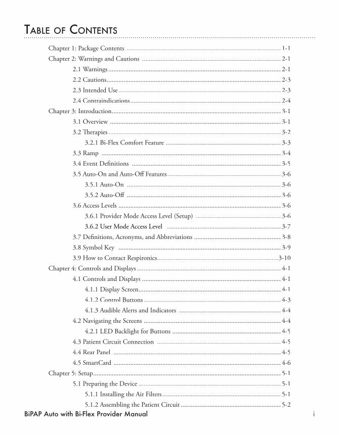
CHAPTER 1: PACKAGE CONTENTS NOTE: Always use these instructions along with the User Manual when assembling
or adjusting this equipment.
BiPAP Auto w/ Bi-Flex
Power Cord
Filter CapReusable Gray Foam Filters
Flexible Tubing
6 ft. (1.83 m) X 22 mm i.d.
User Manual
Disposable Ultrafi ne Filter
External AC Power Supply
Encore® Pro SmartCard™

BiPAP Auto with Bi-Flex Provider Manual1-2

BiPAP Auto with Bi-Flex Provider Manual 2-1
CHAPTER 2: WARNINGS AND CAUTIONS CAUTION! US federal law restricts this device to sale by or on the order of a physi-
cian.
2.1 WARNINGS
WARNING: Indicates the possibility of injury to the patient or the operator.
• Th is manual serves as a reference. Th e instructions in this manual are not intended to supersede the health care professional’s instructions regarding the use of the device.
• Th e operator should read and understand this entire manual before using the device.• Th e device should be used only with masks and connectors recommended by Respironics or with
those recommended by the health care professional or respiratory therapist. See Chapter 10 for approved patient circuits. A mask should not be used unless the device is turned on and operating properly. Th e exhalation port(s) associated with the mask should never be blocked.
Explanation of the Warning: Th e device is intended to be used with special masks or connectors that have exhalation ports to allow continuous fl ow of air out of the mask. When the device is turned on and functioning properly, new air from the device fl ushes the exhaled air out through the mask exhalation port. However, when the device is not operating, enough fresh air will not be provided through the mask, and exhaled air may be rebreathed. Rebreathing of exhaled air for longer than several minutes can in some circumstances lead to suff ocation.
• In the event of a power or device failure, audible and visual alarm signals will activate. Th e device must be disconnected from the patient immediately. As is the case with most therapy devices with passive exhalation ports, when power is lost, suffi cient air will not be provided through the circuit, and exhaled air may be rebreathed.
• At low EPAP pressures, the fl ow through the exhalation port may be inadequate to clear all ex-haled gas from the tubing. Some rebreathing may occur.
• If oxygen is used with the device, the oxygen fl ow must be turned off when the device is not oper-ating.
Explanation of the Warning: When the device is not in operation and the oxygen fl ow is left on, oxygen delivered into the tubing may accumulate within the device’s enclosure. Oxygen accumu-lated in the device enclosure will create a risk of fi re.
• Oxygen supports combustion. Oxygen should not be used while smoking or in the presence of an open flame.
• When using oxygen with this system, a Respironics Pressure Valve (Part Number 302418) must be placed in-line with the patient circuit.
• For proper use, the external AC power supply must be placed feet down, in the upright position.

BiPAP Auto with Bi-Flex Provider Manual2-2
• Operation of the device may be adversely aff ected by: — Electromagnetic fi elds exceeding the level of 10 V/m in the test conditions of EN
60601-1-2— Operation of high frequency (diathermy) equipment— Defi brillators, or short wave therapy equipment— Radiation (e.g., x-ray, CT)— Magnetic fi elds (e.g., MRI)
• Do not use the device in the presence of a flammable anaesthetic mixture in combination with oxygen or air, or in the presence of nitrous oxide.
• Do not use the device at room temperatures above 95° F (35° C). If the device is used at room temperatures above 95° F (35° C), the temperature of the airfl ow may exceed 105° F (41° C), which could cause thermal irritation or injury to the patient’s airway.
• Do not operate the device in direct sunlight or near a heating appliance because these conditions can increase the temperature of the airfl ow delivered to the patient.
• To reduce the risk of contamination, you may place a bacteria filter (Part Number 342077) in-line between the device and the patient.
• Th e device does not have an alarm to detect occlusion of the exhalation port. Before each use, inspect the patient circuit to verify that the port is not occluded. Occlusion or partial occlusion can reduce airfl ow and result in rebreathing of exhaled air.
• Do not use antistatic or electrically conductive hoses or tubing with the device.• When the device is used with a humidifier, position the humidifi er so that the water level in the
humidifi er is lower than the patient, and the humidifi er is on the same level or lower than the device.
• If you detect any unexplained changes in the performance of the device, if the device and/or the power supply is dropped or mishandled, if water is spilled into the enclosure, or if the enclosure is broken, seek the assistance of Respironics or an authorized service center.
• Repairs and adjustments must be performed by Respironics or an authorized service center. Ser-vice done by inexperienced or unqualified personnel, or installation of unauthorized parts could cause injury, invalidate the warranty, or result in costly damage.
• Electrical cords, cables, and the power supply device should be periodically inspected for damage or signs of wear. Replace any damaged parts before using.
• To avoid electrical shock, unplug the device before cleaning it.• Pins of connectors identifi ed with the ESD warning symbol should not be touched. Connec-
tions should not be made to these connectors unless ESD precautionary procedures are used. Precautionary procedures include methods to prevent build-up of electrostatic discharge (e.g., air conditioning, humidifi cation, conductive fl oor coverings, non-synthetic clothing), discharging one’s body to the frame of the equipment or system or to earth or a large metal object, and bond-ing oneself by means of a wrist strap to the equipment or system or to earth.
• Verify the operation of the Patient Disconnect alert with any changes in the patient circuit.• Verify that the Patient Disconnect alert is active if required for medical reasons.
BiPAP Auto with Bi-Flex Provider Manual 2-3
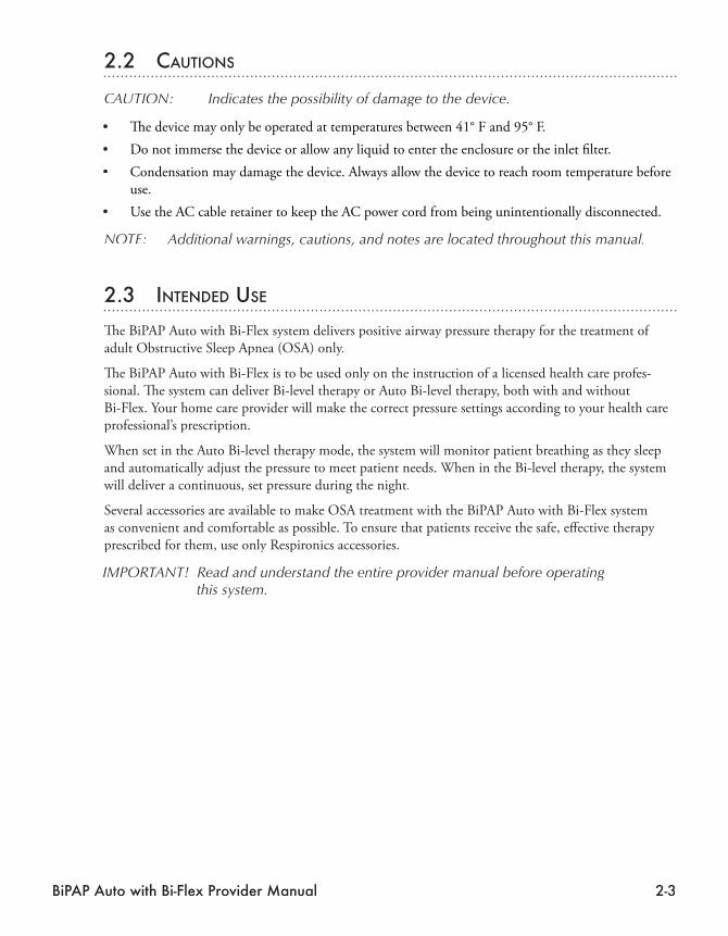
2.2 CAUTIONS
CAUTION: Indicates the possibility of damage to the device.
• Th e device may only be operated at temperatures between 41° F and 95° F.• Do not immerse the device or allow any liquid to enter the enclosure or the inlet filter.• Condensation may damage the device. Always allow the device to reach room temperature before
use.• Use the AC cable retainer to keep the AC power cord from being unintentionally disconnected.
NOTE: Additional warnings, cautions, and notes are located throughout this manual.
2.3 INTENDED USE
Th e BiPAP Auto with Bi-Flex system delivers positive airway pressure therapy for the treatment of adult Obstructive Sleep Apnea (OSA) only.
Th e BiPAP Auto with Bi-Flex is to be used only on the instruction of a licensed health care profes-sional. Th e system can deliver Bi-level therapy or Auto Bi-level therapy, both with and without Bi-Flex. Your home care provider will make the correct pressure settings according to your health care professional’s prescription.
When set in the Auto Bi-level therapy mode, the system will monitor patient breathing as they sleep and automatically adjust the pressure to meet patient needs. When in the Bi-level therapy, the system will deliver a continuous, set pressure during the night.
Several accessories are available to make OSA treatment with the BiPAP Auto with Bi-Flex system as convenient and comfortable as possible. To ensure that patients receive the safe, eff ective therapy prescribed for them, use only Respironics accessories.
IMPORTANT! Read and understand the entire provider manual before operating this system.
BiPAP Auto with Bi-Flex Provider Manual2-4
2.4 CONTRAINDICATIONS
When assessing the relative risks and benefi ts of using this equipment, the clinician should understand that this device can deliver pressures of up to 25 cm H2O. Also, in the unlikely event of certain fault conditions, a maximum pressure of 35 cm H2O is possible. Studies have shown that the follow-ing pre-existing conditions may contraindicate the use of positive airway pressure therapy for some patients:• Bullous lung disease• Bypassed upper airway• Pneumothorax• Pathologically low blood pressure• Pneumocephalus has been reported in a patient using nasal Continuous Positive Airway Pressure.
Caution should be used when prescribing CPAP for susceptible patients such as those with cere-bral spinal fl uid (CSF) leaks, abnormalities of the cribriform plate, prior history of head trauma, and/or pneumocephalus. (Chest 1989; 96:1425-1426)
Th e use of positive airway pressure therapy may be temporarily contraindicated if the patient exhibits signs of a sinus or middle ear infection. Th is therapy is not for use with patients whose upper airways are by-passed. Should your patient have any of these conditions, a physician will determine if Bi-level therapy is appropriate.

BiPAP Auto with Bi-Flex Provider Manual 3-1
CHAPTER 3: INTRODUCTION
3.1 OVERVIEW
WARNING: The device can operate on AC or DC power. The DC power option is not intended as a battery backup during use of AC power.
CAUTION: When DC power is obtained from a vehicle battery, the device should not be used while the vehicle’s engine is running. Damage to the de- vice or the vehicle may occur.
FIGURE 3–1 BIPAP AUTO WITH BI-FLEX DEVICE
Th e device, shown in Figure 3-1, is a low-pressure, electrically driven sleep apnea system with elec-tronic pressure control. Th e device’s pressure controls are adjusted to deliver pressure support to the patient.
Th e device is intended to augment patient breathing by supplying pressurized air through a patient circuit. It senses the patient’s breathing eff ort by monitoring airfl ow in the patient circuit and adjusts its output to assist in inhalation and exhalation. Th is assistance is provided by the administration of two levels of positive pressure. During exhalation, pressure is variably positive or near ambient. During inspiration, pressure is variably positive and always equal to or higher than the expiratory level.

BiPAP Auto with Bi-Flex Provider Manual3-2
3.2 THERAPIES
Th e BiPAP Auto with Bi-Flex device has the following therapies:
Bi-level: Provides one level of output pressure during EPAP (Expiratory Positive Airway Pressure) and a second higher level during IPAP (Inspiratory Positive Airway Pressure). All breaths are patient-triggered, patient-cycled, and pressure controlled.
Bi-level with Bi-Flex: Bi-level therapy with pressure relief upon exhalation to improve patient comfort based on patient needs.
Auto Bi-level: Delivers spontaneous Bi-level therapy with automatically adjusting EPAP and IPAP levels that adjust to meet the patient’s needs.
Auto Bi-level with Bi-Flex: Auto Bi-level therapy with pressure relief upon exhalation to improve patient comfort based on patient needs.
Th e device triggers to Inspiratory Positive Airway Pressure (IPAP) in response to spontaneous inspira-tory eff ort and cycle to Expiratory Positive Airway Pressure (EPAP) during exhalation. Figure 3-2 illustrates the trigger and cycle concepts.
FIGURE 3-2 TRIGGERING AND CYCLING
Th e level of pressure support (PS) delivered is determined by the diff erence between the IPAP and EPAP settings (PS = IPAP - EPAP).
When the device is in Provider access mode, you can confi gure the following settings:• Th erapy mode setting (bPAP for Bi-level mode, bFLE for Bi-level with Bi-Flex mode, AbPAP for
Auto Bi-level mode, and AbFLE for Auto Bi-level with Bi-Flex mode)• IPAP setting• EPAP setting• Min EPAP setting• Max IPAP setting• Max PS setting• Flex setting• Rise time setting• Ramp length setting• Ramp start pressure setting• Split night time setting• Patient disconnect alert (enable/disable)
BiPAP Auto with Bi-Flex Provider Manual 3-3
• Erase therapy hours • LED backlight setting (enable/disable)• Humidifi er heat setting (for Respironics REMstar Heated Humidifi er only)
3.2.1 BI-FLEX COMFORT FEATURE
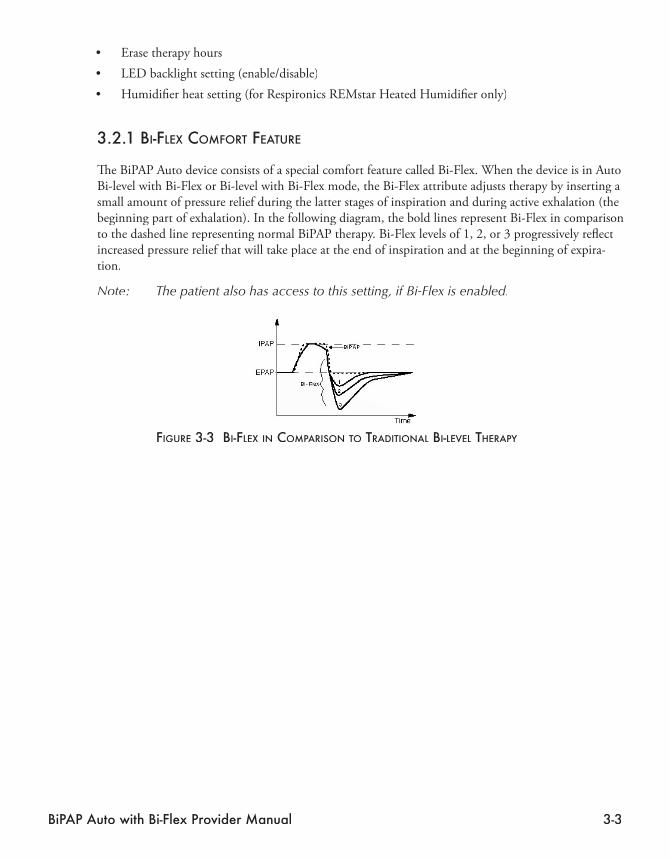
Th e BiPAP Auto device consists of a special comfort feature called Bi-Flex. When the device is in Auto Bi-level with Bi-Flex or Bi-level with Bi-Flex mode, the Bi-Flex attribute adjusts therapy by inserting a small amount of pressure relief during the latter stages of inspiration and during active exhalation (the beginning part of exhalation). In the following diagram, the bold lines represent Bi-Flex in comparison to the dashed line representing normal BiPAP therapy. Bi-Flex levels of 1, 2, or 3 progressively refl ect increased pressure relief that will take place at the end of inspiration and at the beginning of expira-tion.
Note: The patient also has access to this setting, if Bi-Flex is enabled.
FIGURE 3-3 BI-FLEX IN COMPARISON TO TRADITIONAL BI-LEVEL THERAPY
BiPAP Auto with Bi-Flex Provider Manual3-4
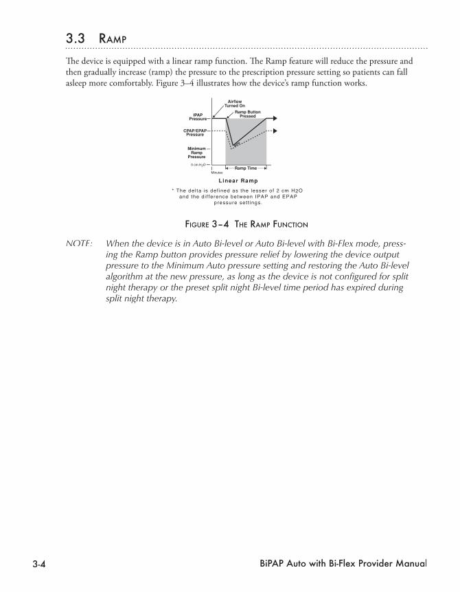
3.3 RAMP Th e device is equipped with a linear ramp function. Th e Ramp feature will reduce the pressure and then gradually increase (ramp) the pressure to the prescription pressure setting so patients can fall asleep more comfortably. Figure 3–4 illustrates how the device’s ramp function works.
FIGURE 3–4 THE RAMP FUNCTION
NOTE: When the device is in Auto Bi-level or Auto Bi-level with Bi-Flex mode, press-ing the Ramp button provides pressure relief by lowering the device output pressure to the Minimum Auto pressure setting and restoring the Auto Bi-level algorithm at the new pressure, as long as the device is not confi gured for split night therapy or the preset split night Bi-level time period has expired during split night therapy.
0 cm H2O
Minutes
IPAPPressure
CPAP/EPAPPressure
MinimumRamp
Pressure
Ramp Time
AirflowTurned On
Ramp ButtonPressed
Linear Ramp
* The del ta is def ined as the lesser o f 2 cm H2O and the d i f ference between IPAP and EPAP
pressure set t ings.
delta
BiPAP Auto with Bi-Flex Provider Manual 3-5
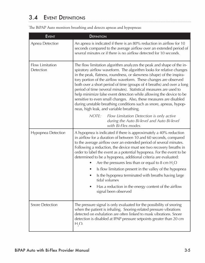
3.4 EVENT DEFINITIONS Th e BiPAP Auto monitors breathing and detects apneas and hypopneas:
EVENT DEFINITION
Apnea Detection An apnea is indicated if there is an 80% reduction in airfl ow for 10 seconds compared to the average airfl ow over an extended period of several minutes or if there is no airfl ow detected for 10 seconds.
Flow Limitation Detection
The fl ow limitation algorithm analyzes the peak and shape of the in-spiratory airfl ow waveform. The algorithm looks for relative changes in the peak, fl atness, roundness, or skewness (shape) of the inspira-tory portion of the airfl ow waveform. These changes are observed both over a short period of time (groups of 4 breaths) and over a long period of time (several minutes). Statistical measures are used to help minimize false event detection while allowing the device to be sensitive to even small changes. Also, these measures are disabled during unstable breathing conditions such as snore, apneas, hypop-neas, high leak, and variable breathing.
NOTE: Flow Limitation Detection is only active during the Auto Bi-level and Auto Bi-level with Bi-Flex modes.
Hypopnea Detection A hypopnea is indicated if there is approximately a 40% reduction in airfl ow for a duration of between 10 and 60 seconds, compared to the average airfl ow over an extended period of several minutes. Following a reduction, the device must see two recovery breaths in order to label the event as a potential hypopnea. For the event to be determined to be a hypopnea, additional criteria are evaluated:
• Are the pressures less than or equal to 8 cm H2O
• Is fl ow limitation present in the valley of the hypopnea
• Is the hypopnea terminated with breaths having large tidal volumes
• Has a reduction in the energy content of the airfl ow signal been observed
Snore Detection The pressure signal is only evaluated for the possibility of snoring when the patient is inhaling. Snoring-related pressure vibrations detected on exhalation are often linked to mask vibrations. Snore detection is disabled at IPAP pressure setpoints greater than 20 cm H2O.

BiPAP Auto with Bi-Flex Provider Manual3-6
3.5 AUTO-ON AND AUTO-OFF FEATURES Th e device includes automatic pressure activation (Auto-On) and automatic pressure cessation (Auto-Off ) features.
3.5.1 AUTO-ON
With the Auto-On feature, the device automatically transitions from the Standby state to the Operate state when the patient begins breathing on the device (after 3 consecutive breaths).
3.5.2 AUTO-OFF
Setting the Patient Disconnect setting to 1 enables the Auto-Off feature (in addition to enabling the Patient Disconnect alert). When Auto-Off is enabled, the device automatically transitions from the Operate state to the Standby state when the patient removes the mask from the airway. Th e device will transition to standby within one and a half to two minutes following removal of the mask.
3.6 ACCESS LEVELS Th ere are two levels of access for the device: Provider Mode and User Mode.
3.6.1 PROVIDER MODE ACCESS LEVEL (SETUP)
Th e Provider mode unlocks additional parameters that are not available to the patient. Providers can temporarily access these parameters via the user interface by completing the following steps:1. Press the Left and Right user buttons down simultaneously.2. With the user buttons pressed down, plug in the device to power up the unit.3. Release the Left and Right user buttons when you see the word SETUP appear in the top right
corner of the display. Th is indicates that you are now in Provider mode.
NOTE: If the device is already on, you must fi rst turn the device off and unplug it before entering Provider mode.
Right UserButton
Left UserButton
Start/Stop ButtonRamp Button
Humidifier Button
FIGURE 3-5 DEVICE CONTROL PANEL

BiPAP Auto with Bi-Flex Provider Manual 3-7
• LED Backlight setting• Maximum IPAP and minimum EPAP auto pressure• Split night BiPAP time• Maximum PS
Th e following is also true in Provider mode:• Th e IPAP and EPAP setting screens only display if the device is in Bi-level or Bi-level with Bi-Flex
mode.• Th e Rise Time screen is only displayed if the device is in Bi-level mode and IPAP is not equal to
EPAP, or if the device is in Auto Bi-level mode.• Th e Ramp Start Pressure screen is only displayed if the device is in Bi-level or Bi-level with Bi-Flex
mode and the Ramp length setting is between 5 and 45 minutes.• Th e Flex Setting screen is only displayed if the device is in Auto Bi-level with Bi-Flex or Bi-level
with Bi-Flex mode.• Th e Split Night Time screen only displays if the device is in Auto Bi-level or Auto Bi-level with
Bi-Flex mode.• Th e Max IPAP, Min EPAP, and Max PS screens only display if the device is in Auto Bi-level or
Auto Bi-level with Bi-Flex mode.
3.6.2 USER MODE ACCESS LEVEL
Th e device defaults to User mode upon startup. Users can access user mode settings by pressing and holding the Ramp button while the device is in standby.
NOTE: If you temporarily set the device to Provider mode by pressing the Left andRight User buttons, the unit will return to User mode when any of the follow-Right User buttons, the unit will return to User mode when any of the follow-Right Usering occurs:• The Start/Stop button is pressed.• Any user interface button is not pressed for more than 60 seconds.• The device is unplugged and then powered up again.
Th e following settings can be modifi ed in User mode when the user presses and holds the Ramp but-ton for several seconds:• Flex setting (when Bi-Flex is enabled by the Provider)• Rise time setting (when in Bi-level or Auto Bi-level mode)• Ramp start pressure setting (when ramp enabled by Provider)• LED backlight for control buttons (enable/disable)• Patient disconnect alert (enable/disable)• Answers to FOSQ test questions (when the SmartCard is inserted)
Additionally, the Humidifi er heat setting can be modifi ed by pressing and holding the Heat button.
BiPAP Auto with Bi-Flex Provider Manual3-8
Th e following is also true in User mode:• Th e Flex Setting screen is only displayed if the device is in Auto Bi-level with Bi-Flex or Bi-level
with Bi-Flex mode.• Th e Rise Time screen is only displayed if the device is in Bi-level mode and IPAP is not equal to
EPAP, or if the device is in Auto Bi-level mode.• Th e Ramp Start Pressure Setting screen is only displayed if the device is in Bi-level or Bi-level with
Bi-Flex mode and the Ramp length is between 5 and 45 minutes.• Th e FOSQ screen is only displayed if the SmartCard is inserted prior to entering the user mode
setting screens.
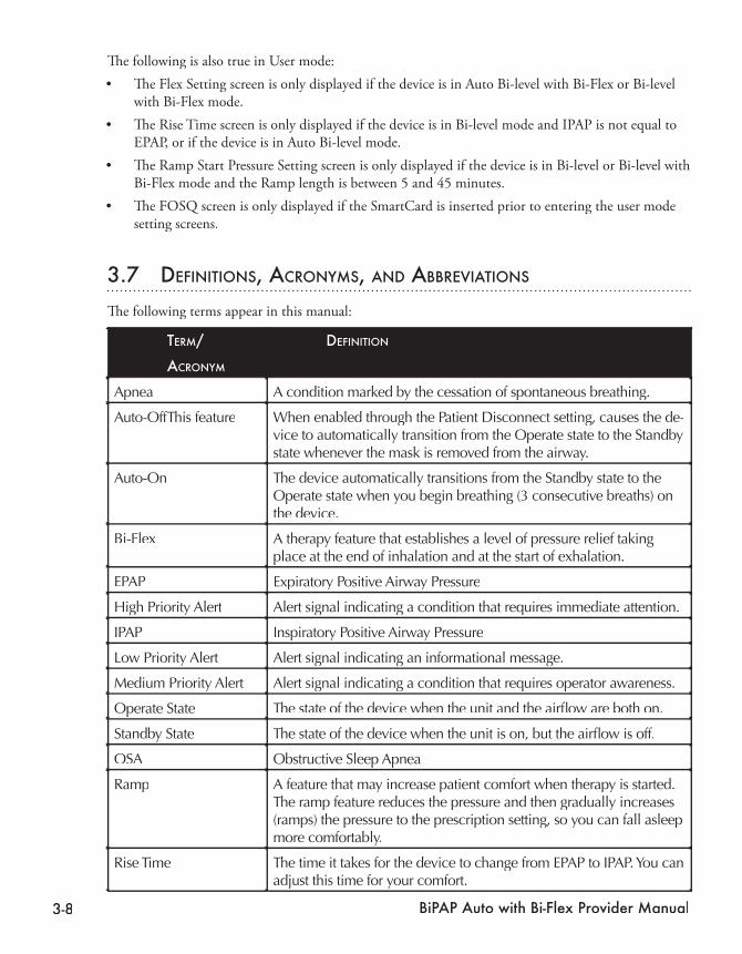
3.7 DEFINITIONS, ACRONYMS, AND ABBREVIATIONS Th e following terms appear in this manual:
TERM/
ACRONYM
DEFINITION
Apnea A condition marked by the cessation of spontaneous breathing.
Auto-Off This feature When enabled through the Patient Disconnect setting, causes the de-vice to automatically transition from the Operate state to the Standby state whenever the mask is removed from the airway.
Auto-On The device automatically transitions from the Standby state to the Operate state when you begin breathing (3 consecutive breaths) on the device.
Bi-Flex A therapy feature that establishes a level of pressure relief taking place at the end of inhalation and at the start of exhalation.
EPAP Expiratory Positive Airway Pressure
High Priority Alert Alert signal indicating a condition that requires immediate attention.
IPAP Inspiratory Positive Airway Pressure
Low Priority Alert Alert signal indicating an informational message.
Medium Priority Alert Alert signal indicating a condition that requires operator awareness.
Operate State The state of the device when the unit and the airfl ow are both on.
Standby State The state of the device when the unit is on, but the airfl ow is off.
OSA Obstructive Sleep Apnea
Ramp A feature that may increase patient comfort when therapy is started. The ramp feature reduces the pressure and then gradually increases (ramps) the pressure to the prescription setting, so you can fall asleep more comfortably.
Rise Time The time it takes for the device to change from EPAP to IPAP. You can adjust this time for your comfort.

BiPAP Auto with Bi-Flex Provider Manual 3-9
3.8 SYMBOL KEY Th e following symbols appear on the device label:
SYMBOL DESCRIPTION
Consult accompanying instructions for use.
DC Power
Type BF Applied Part
Class II (Double Insulated)
IPX1 Drip Proof Equipment
Electrostatic Discharge
0123European Declaration of Conformity
Canadian/US Certifi cation
Notifi ed Body Approval for Standards Compliance
TUV Safety Standard Compliance
UL Recognized for Canada and the United States
No User Serviceable Parts

BiPAP Auto with Bi-Flex Provider Manual3-10
3.9 HOW TO CONTACT RESPIRONICS
To have your unit serviced, contact your home care provider. If you need to contact Respironics directly, call 1-800-345-6443 or use the following address:

BiPAP Auto with Bi-Flex Provider Manual 4-1
CHAPTER 4: CONTROLS AND DISPLAYS
Th is chapter describes the device control panel and displays, patient circuit connections, and rear panel connections.
4.1 CONTROLS AND DISPLAYS
Start/Stop
Button
Display
Screen
Ramp
Button
Heated
Humidifier
Button
FIGURE 4-1 CONTROL PANEL
Figure 4-1 illustrates the device control panel, which includes:• A display screen where all device settings appear• Control buttons
4.1.1 DISPLAY SCREEN
Th e display screen shows operating parameters, instructions, and messages. Figure 4-2 shows the device’s display screen.
FIGURE 4–2 DISPLAY SCREEN
Th e information shown on the display screen is defi ned as follows:
TEXT DESCRIPTION
ALERT Indicates that the device requires user attention as indicated on the screen.
AUTO Indicates that Auto mode is active.
CARD Indicates that a SmartCard is inserted and detected.

BiPAP Auto with Bi-Flex Provider Manual4-2
TEXT DESCRIPTION
cm H2O Indicates that the alphanumeric digits are displaying a pressure value.
EPAP Indicates that the EPAP pressure or Max EPAP pres-sure is being displayed.
Erase Indicates that the user may clear the Therapy Session Counter.
FLEX Indicates that a Bi-Flex comfort setting is being dis-played or that Bi-Flex is active.
FOSQ Indicates that the user may begin the FOSQ test or that the FOSQ test is active.
HEAT Indicates that the humidifi er is turned on and/or its setting is displayed.
HOURS Indicates that the Therapy Time is being displayed.
IPAP Indicates that the IPAP pressure or Max IPAP pressure is being displayed.
Light Indicates that the control panel LED backlight setting is being displayed or is active.
Max IPAP/Max PS Indicates that the Max IPAP setting or Max PS setting is being displayed.
Min EPAP Indicates that the Min EPAP setting is being dis-played.
NIGHTS Indicates that the session counter is being displayed.
PATIENT Indicates that a Patient Disconnect alert is active.
PS Indicates that the Pressure Support setting is being displayed.
RAMP Indicates that the ramp function is in progress.
RAMP START Indicates that the ramp starting pressure is being diplayed.
RISE Indicates that a rise time setting is being displayed.
Setup Indicates that the device is in Provider mode and not in User mode.

BiPAP Auto with Bi-Flex Provider Manual 4-3
4.1.2 CONTROL BUTTONS
Th e device control buttons, shown in Figure 4-3, are defi ned below.
Start/Stop
Button
Display
Screen
Ramp
Button
Heated
Humidifier
Button
User
Buttons
FIGURE 4–3 CONTROL BUTTONS
BUTTON DESCRIPTION
START/STOP This button starts or stops the unit’s airfl ow. Press the button in to turn the airfl ow on and put the device in the Operate state. When the button is turned off, the device is in the Standby state. When in Standby, any ramp in progress is terminated, the alerts are reset (except for the System Errors alert), and the humidi-fi er is turned off. This button is also used to exit the parameter screens.
HEAT When the optional REMstar Heated Humidifi er is prescribed, this button controls the humidifi er’s heater plate setting. Fol-low the instructions provided with the humidifi er. You can also use this button to adjust the settings shown in the user menu screens.
RAMP When the airfl ow is turned on and the ramp function is enabled, this button lowers the airfl ow pressure, allowing you to fall asleep more easily. You can also use this button to adjust the set-tings shown in the user menu screens.
USER The left and right user buttons allow you to navigate the display screens.
NOTE: Additionally, you can press any of the above buttons to clear the patient dis-connect alert or to silence the high priority alert.

BiPAP Auto with Bi-Flex Provider Manual4-4
4.1.3 AUDIBLE ALERTS AND INDICATORS
Th e device provides audible and visual indicators of alert conditions. Th ese indicators occur in the following situations:• Power On – All visual indicators appear momentarily, and the audible indicator briefl y sounds to
signify that all indicators are functioning properly.• Continuous alerts – An alert sounds continuously.• High priority alerts – An alert consisting of three beeps, a pause, and then two more beeps sounds
several times at intervals for a high priority alert.• Medium priority alerts – An alert sounds repeatedly, with a brief interval between alerts for a
medium priority alert.• Low priority system alerts – An alert sounds repeatedly, with a longer interval between alerts for a
low priority alert.• Provider mode – An alert sounds when the provider mode is accessed using the button sequence
described in Section 3.6.1.• SmartCard activity – An alert sounds once when the SmartCard is inserted or removed.• SmartCard error – A medium priority alert sounds and the CARD icon and an error code appear
on the display when a card error occurs.• Patient Disconnect – A low priority alert sounds and the ALERT and PATIENT icons fl ash on
the display.• Confi rmation – An alert sounds once when the humidifi er setting screen is entered and when the
humidifi er is turned on.
4.2 NAVIGATING THE SCREENS Note the following when navigating the Provider or User mode screens:• Th e Left and Right User buttons allow you to go to the previous or next setting, respectively.• Th e Heat and Ramp buttons operate as up and down buttons to adjust the settings. Pressing and
holding the Heat or Ramp button down for at least 2 seconds will change the settings at a faster rate.
• Th e Start/Stop button allows you to exit a provider or user mode screen.• Th e alphanumeric digits and icons fl ash to indicate setting adjustment.
BiPAP Auto with Bi-Flex Provider Manual 4-5
4.2.1 LED BACKLIGHT FOR BUTTONS
Th e Start/Stop, Ramp, and Heat buttons can be lit by an LED backlight. Th e LED backlight is on when the device is in the Standby state. When the device is in the Operate state, the LED backlight is lit according to the setting in the LED backlight setting. Th e LED backlight may fl ash to indicate an alert condition.
CONTROL PAD INACTIVITY Some screens have timeout periods. Th e screen’s timer starts when the screen is initially displayed, and is restarted whenever a button is pressed. When a screen times out, the Monitoring/Standby screen is displayed.
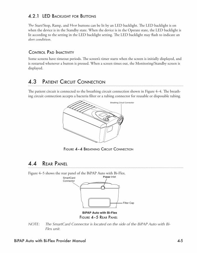
4.3 PATIENT CIRCUIT CONNECTION Th e patient circuit is connected to the breathing circuit connection shown in Figure 4–4. Th e breath-ing circuit connection accepts a bacteria fi lter or a tubing connector for reusable or disposable tubing.
Breathing Circuit Connection
FIGURE 4–4 BREATHING CIRCUIT CONNECTION
4.4 REAR PANEL Figure 4–5 shows the rear panel of the BiPAP Auto with Bi-Flex.
FIGURE 4–5 REAR PANEL
NOTE: The SmartCard Connector is located on the side of the BiPAP Auto with Bi-Flex unit.
BiPAP Auto with Bi-Flex Provider Manual4-6
Th e BiPAP Auto with Bi-Flex rear panel contains the following:• A power inlet for connecting either the external AC power supply or a DC power adapter.• Th e fi lter cap that is removed to inspect the inlet air fi lters.
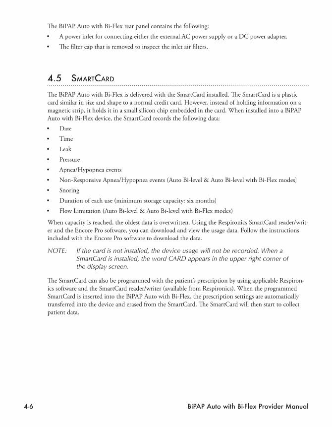
4.5 SMARTCARD Th e BiPAP Auto with Bi-Flex is delivered with the SmartCard installed. Th e SmartCard is a plastic card similar in size and shape to a normal credit card. However, instead of holding information on a magnetic strip, it holds it in a small silicon chip embedded in the card. When installed into a BiPAP Auto with Bi-Flex device, the SmartCard records the following data:• Date• Time• Leak • Pressure• Apnea/Hypopnea events• Non-Responsive Apnea/Hypopnea events (Auto Bi-level & Auto Bi-level with Bi-Flex modes)• Snoring• Duration of each use (minimum storage capacity: six months)• Flow Limitation (Auto Bi-level & Auto Bi-level with Bi-Flex modes)
When capacity is reached, the oldest data is overwritten. Using the Respironics SmartCard reader/writ-er and the Encore Pro software, you can download and view the usage data. Follow the instructions included with the Encore Pro software to download the data.
NOTE: If the card is not installed, the device usage will not be recorded. When a SmartCard is installed, the word CARD appears in the upper right corner of the display screen.
Th e SmartCard can also be programmed with the patient’s prescription by using applicable Respiron-ics software and the SmartCard reader/writer (available from Respironics). When the programmed SmartCard is inserted into the BiPAP Auto with Bi-Flex, the prescription settings are automatically transferred into the device and erased from the SmartCard. Th e SmartCard will then start to collect patient data.
BiPAP Auto with Bi-Flex Provider Manual 5-1
CHAPTER 5: SETUP
5.1 PREPARING THE DEVICE
Th is section contains information on:• Installing the air fi lters• Assembling the patient circuit• Supplying power to the device• Startup• Entering Provider mode
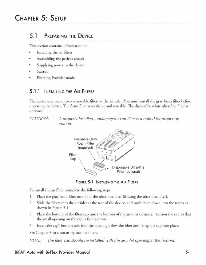
5.1.1 INSTALLING THE AIR FILTERS
Th e device uses one or two removable fi lters at the air inlet. You must install the gray foam fi lter before operating the device. Th e foam fi lter is washable and reusable. Th e disposable white ultra-fi ne fi lter is optional.
CAUTION: A properly installed, undamaged foam fi lter is required for proper op- eration.
Reusable GrayFoam Filter(required)
Disposable Ultra-fineFilter (optional)
FilterCap
(required)
FIGURE 5-1 INSTALLING THE AIR FILTERS
To install the air fi lter, complete the following steps:1. Place the gray foam fi lter on top of the ultra-fi ne fi lter (if using the ultra-fi ne fi lter).2. Slide the fi lters into the air inlet at the rear of the device, and push them down into the recess as
shown in Figure 5-1.3. Place the bottom of the fi lter cap into the bottom of the air inlet opening. Position the cap so that
the small opening on the cap is facing down.4. Insert the cap’s bottom tabs into the opening below the fi lter area. Snap the cap into place.
See Chapter 8 to clean or replace the fi lters.
NOTE: The fi lter cap should be installed with the air inlet opening at the bottom.
BiPAP Auto with Bi-Flex Provider Manual5-2
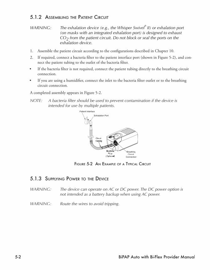
5.1.2 ASSEMBLING THE PATIENT CIRCUIT
WARNING: The exhalation device (e.g., the Whisper Swivel® II) or exhalation port (on masks with an integrated exhalation port) is designed to exhaust CO2 from the patient circuit. Do not block or seal the ports on the exhalation device.
1. Assemble the patient circuit according to the confi gurations described in Chapter 10.2. If required, connect a bacteria fi lter to the patient interface port (shown in Figure 5-2), and con-
nect the patient tubing to the outlet of the bacteria fi lter.• If the bacteria fi lter is not required, connect the patient tubing directly to the breathing circuit
connection.• If you are using a humidifi er, connect the inlet to the bacteria fi lter outlet or to the breathing
circuit connection.
A completed assembly appears in Figure 5-2.
NOTE: A bacteria fi lter should be used to prevent contamination if the device is intended for use by multiple patients.
BreathingCircuit
Connection
Patient Interface
Breathing
Exhalation Port
FIGURE 5-2 AN EXAMPLE OF A TYPICAL CIRCUIT
5.1.3 SUPPLYING POWER TO THE DEVICE
WARNING: The device can operate on AC or DC power. The DC power option is not intended as a battery backup when using AC power.
WARNING: Route the wires to avoid tripping.
BiPAP Auto with Bi-Flex Provider Manual 5-3
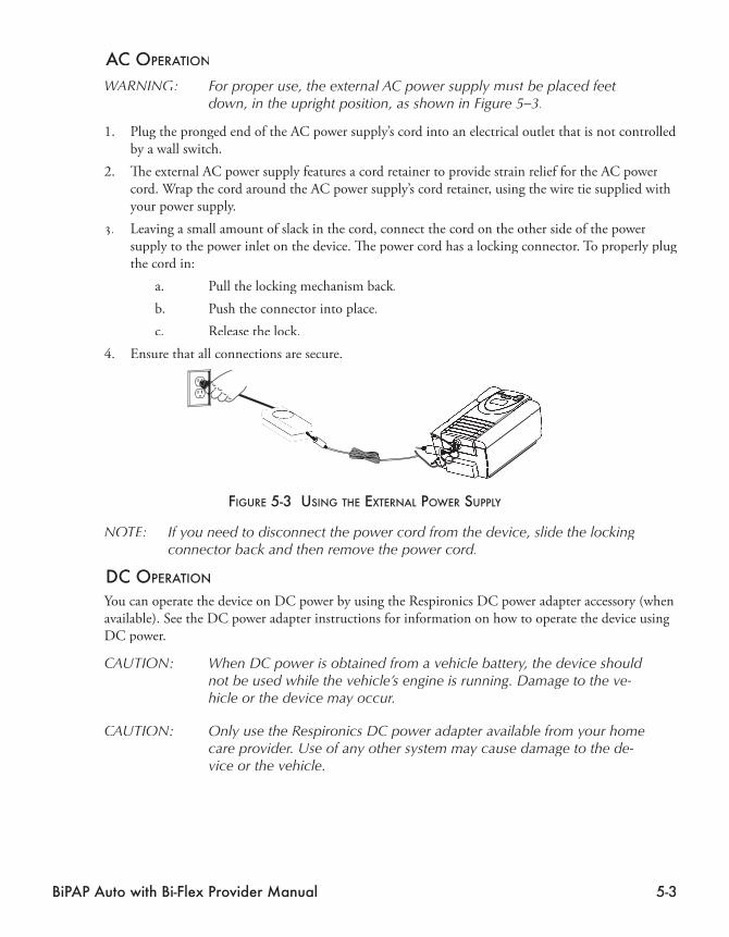
AC OPERATION
WARNING: For proper use, the external AC power supply must be placed feet down, in the upright position, as shown in Figure 5–3.
1. Plug the pronged end of the AC power supply’s cord into an electrical outlet that is not controlled by a wall switch.
2. Th e external AC power supply features a cord retainer to provide strain relief for the AC power cord. Wrap the cord around the AC power supply’s cord retainer, using the wire tie supplied with your power supply.
3. Leaving a small amount of slack in the cord, connect the cord on the other side of the power supply to the power inlet on the device. Th e power cord has a locking connector. To properly plug the cord in:
a. Pull the locking mechanism back. b. Push the connector into place. c. Release the lock.
4. Ensure that all connections are secure.
FIGURE 5-3 USING THE EXTERNAL POWER SUPPLY
NOTE: If you need to disconnect the power cord from the device, slide the locking connector back and then remove the power cord.
DC OPERATION
You can operate the device on DC power by using the Respironics DC power adapter accessory (when available). See the DC power adapter instructions for information on how to operate the device using DC power.
CAUTION: When DC power is obtained from a vehicle battery, the device should not be used while the vehicle’s engine is running. Damage to the ve- hicle or the device may occur.
CAUTION: Only use the Respironics DC power adapter available from your home care provider. Use of any other system may cause damage to the de- vice or the vehicle.

BiPAP Auto with Bi-Flex Provider Manual5-4
5.1.4 STARTUP
When the power cord is plugged into an AC or DC power source, the device sounds a confi rmation alarm, and the control panel buttons light up.
NOTE: If the alarm does not sound or the buttons do not light up, the device requires servicing. Additionally, if any of the alphanumeric digits shown in Figure 5–4 do not display on the Self Test screen, the device requires servicing.
1. Th e fi rst screen to appear is the Self Test screen:
FIGURE 5-4 SELF TEST SCREEN
2. Th e next screen displays the software version:
FIGURE 5-5 SOFTWARE VERSION SCREEN
3. Th e Blower Hours Screen then appears, which displays the Blower Hours Time Meter:
FIGURE 5-6 BLOWER HOURS SCREEN
NOTE: The control panel is inactive during these fi rst three screens.
NOTE: Each of the fi rst three screens appears for approximately 1-3 seconds.

BiPAP Auto with Bi-Flex Provider Manual 5-5
4. Th e next screen to appear is the Standby screen:
FIGURE 5-7 STANDBY SCREEN
Th e Standby screen appears when the device is in the Standby state and displays the Th erapy Time Meter. Pressing the Start/Stop button puts the device in the Operate state. Th e Moni-toring screen then appears, displaying the current pressure setting:
FIGURE 5-8 MONITORING SCREEN
Both the Monitoring and the Standby screens display the PATIENT, FLEX, and LIGHT icons if these features are enabled. Additionally, the CARD icon displays if a SmartCard is inserted, and the AUTO icon displays if the device is in Auto Bi-level or Auto Bi-level with Bi-Flex mode. Th e HEAT icon also displays if the humidifi er is turned on. Th e RAMP icon is displayed in Monitoring Screen if ramp is active.5. When in the Standby or Monitoring screens, you can modify the humidifi er setting
by pressing and holding the Heat button until the screen below appears (Figure 5–9).
FIGURE 5–9 HUMIDIFIER SETTING SCREEN
You can increase or decrease the humidifi er setting from 1 to 5 in increments of 1. Th e setting changes immediately as you adjust it. When the START/STOP button is pressed to exit this screen, the Operate/Standby state does not change.

BiPAP Auto with Bi-Flex Provider Manual5-6
5.1.5 ENTERING PROVIDER MODE
Enter Provider mode by completing the following steps:1. Unplug the device if it is already plugged in.2. Hold down the Left and Right User buttons simultaneously. 3. Plug the device in. Th e SETUP icon appears in the upper right corner of the screen to indicate
that the device is in Provider mode. Release the Left and Right User buttons.
IMPORTANT: Prescribed therapy settings can only be set in Provider mode. To prevent patients from tampering with the settings, do not show them how to access Provider mode.
5.2 CONNECTING THE PATIENT
NOTE: Before connecting the patient to the device, check the integrity of the patient circuit, exhalation port, and alarms.
1. Turn the device’s airfl ow on by pressing the Start/Stop button.2. If oxygen is being used, turn on the oxygen fl ow. Make sure you place the Respironics Pressure
Valve (Part Number 302418) in-line with the patient circuit.
WARNING: Always turn the airfl ow on before turning on the oxygen, and always turn the oxygen off before turning off the airfl ow.
3. Place the mask on the patient.
5.3 SETTING UP THE SMARTCARD
Th is section provides information on:• Downloading data• Programming a SmartCard• Changing Settings using a SmartCard
5.3.1 DOWNLOADING DATA
You can download data from the SmartCard by completing the following steps:1. Connect a Respironics SmartCard reader/writer directly to a Windows-compatible computer fol-
lowing the instructions included with the reader/writer. Remove the SmartCard from the device and insert it into the reader/writer.
2. Follow the instructions included with your Encore Pro software to download the data.
WARNING: Any IEC 60950 device must be connected through the 7-pin mini-din connector with a Respironics-supplied isolation cable.

BiPAP Auto with Bi-Flex Provider Manual 5-7
5.3.2 PROGRAMMING A SMARTCARD
1. Connect a Respironics SmartCard reader/writer directly to a Windows-compatible computer fol-lowing the instructions included with the reader/writer. Remove the SmartCard from the device and insert it into the reader/writer.
2. Follow the instructions included with your Encore Pro software to program the SmartCard.3. Remove the SmartCard from the reader/writer. If desired, write the patient’s name on the front of
the card.
5.3.3 CHANGING SETTINGS USING A SMARTCARD
To change the settings in the device using a programmed SmartCard:1. Make sure the device is plugged in. Insert the programmed SmartCard into the slot on the left
side of the device (logo side facing up). When the Monitoring or Standby screen displays, the word CARD appears in the upper right corner indicating that the card is inserted correctly.
2. Turn the airfl ow on to verify the new prescription setting. Th e card can now be removed or you can leave the card in the device to record device usage. Once the prescription settings have been transferred to the device, they will be deleted from the SmartCard.

BiPAP Auto with Bi-Flex Provider Manual5-8

BiPAP Auto with Bi-Flex Provider Manual 6-1
CHAPTER 6: CHANGING SETTINGS
Th is chapter describes the settings that can be changed when the device is in the Provider and User modes.
6.1 CHANGING SETTINGS IN THE PROVIDER MODE
Accessing the Provider mode setup level unlocks additional settings that cannot be changed while in User mode.
6.1.1 PROVIDER MODE NAVIGATION
Figure 6–1 shows how to navigate the Provider mode screens using the Left and Right User buttons. Th e parameter icon and setting will fl ash.
Right UserButton
Right UserButton
Left UserButton
Left UserButton
Right UserButton
Left UserButton
Right UserButton
Left UserButton
Right UserButton
Left UserButton
Right UserButton
Left UserButton
Right UserButton
Left UserButton
Right UserButton
Left UserButton
Right UserButton
Left UserButton
Mode Setting Screen
IPAPIPAPIP Setting Screen
EPAPEPAPEP Setting Screen
Max PS Setting Screen
Right UserButton
Left UserButton
Ramp Length Setting Screen
Ramp Start PressureSetting Screen
Flex Setting Screen
Patient Disconnect Alert Setting Screen
Reset Session Counter Setting Screen
LED Backlight Setting Screen
Right UserButton
Left UserButton
Right UserButton
Left UserButton
Right UserButton
Left UserButton
Right UserButton
Left UserButton
Min EPAPMin EPAPMin EP Setting Screen
Max IPAPMax IPAPMax IP Setting Screen
Rise Time Setting Screen
Split Night Time Setting Screen
Only displayed if the deviceis in Bi-level or Bi-level with Bi-Flex mode.
Only displayed if the deviceis in Auto Bi-level or AutoBi-level with Bi-Flex mode.
Only displayed if the deviceis in Auto Bi-level or AutoBi-level with Bi-Flex mode.
Only displayed if the deviceis in Auto Bi-level or AutoBi-level with Bi-Flex mode.
Only displayed if the deviceis in Bi-level with Bi-Flex or Auto Bi-level with Bi-Flex mode.
Only displayed if the deviceis in Bi-level mode and IPAP does notequal EPAPequal EPAPequal EP , or if the device is inAuto Bi-level mode.
Only displayed if the device is in Bi-level or Bi-level with Bi-Flex mode.
Only displayed if the device is in Bi-level or Bi-level with Bi-Flex mode and the Ramp Length Setting is between 5 and 45 minutes.
Only displayed if the device is in Auto Bi-level or Auto Bi-level with Bi-Flex mode.
Only displayed if the deviceis in Bi-level or Bi-level with Bi-Flex mode.
FIGURE 6–1 NAVIGATING THE PROVIDER MODE SCREENS

BiPAP Auto with Bi-Flex Provider Manual6-2
6.1.1.1 CHANGING THE PROVIDER MODE SETTINGS1. Mode Setting ScreenFor BiPAP Auto with Bi-Flex devices, the Mode Setting screen appears after the Software Version
screen when you fi rst enter Provider mode. Th is screen, shown in Figure 6–2, allows you to select the therapy mode. Th e available modes are: Bi-level, Bi-level with Bi-Flex, Auto Bi-level, and Auto Bi-level with Bi-fl ex (bPAP, bFLE, AbFLE, and AbPAP on the display).
To change the selection, press the Heat or Ramp buttons until the correct setting appears. Th e icons fl ash when selected to indicate the current therapy.
FIGURE 6–2 MODE SETTING SCREEN
Press the Right User button to access the Pressure Setting screens.
2. Bi-level and Bi-level with Bi-Flex Pressure Settings
NOTE: These screens are only displayed if the device is in Bi-level or Bi-level with Bi-Flex mode.
NOTE: IPAP cannot be set lower than EPAP, and EPAP cannot be set higher than IPAP.
a. IPAP Setting Screen
Th e IPAP Setting screen is shown in Figure 6–3. It allows you to modify the IPAP setting.
FIGURE 6–3 IPAP SETTING SCREEN
Increase or decrease the IPAP pressure by pressing the Heat and Ramp buttons until the correct pres-sure appears. You can adjust the pressure in 0.5 cm H2O increments. Th e setting can be adjusted from 4 to 25 cm H2O.
Press the Right User button to access the EPAP pressure setting.
BiPAP Auto with Bi-Flex Provider Manual 6-3
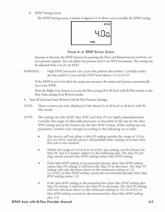
b. EPAP Setting Screen Th e EPAP Setting screen is shown in fi gure 6-4. It allows you to modify the EPAP setting.
FIGURE 6–4 EPAP SETTING SCREEN
Increase or decrease the EPAP pressure by pressing the Heat and Ramp buttons until the cor-rect pressure appears. You can adjust the pressure in 0.5 cm H2O increments. Th e setting can be adjusted from 4 to 25 cm H2O.
WARNING: High EPAP pressures can cause the patient discomfort. Carefully evalu- ate the patient if you set the EPAP level above 15 cm H2O.
If the EPAP is set to less than the ramp start pressure, the ramp start pressure automatically sets to the EPAP.
Press the Right User button to access the Flex setting (if in Bi-level with Bi-Flex mode) or the Rise Time setting (if in Bi-level mode).
3. Auto Bi-level and Auto Bi-level with Bi-Flex Pressure Settings
NOTE: These screens are only displayed if the device is in Bi-level or Bi-level with Bi-Flex mode.
NOTE: The settings for Min EPAP, Max IPAP, and Max PS are highly interdependent. Consider the range of allowable pressures as bounded at the top by the Max IPAP setting and at the bottom by the Min EPAP setting. While setting up one parameter, another may change according to the following set of rules:
• The device will not allow a Max PS setting outside the range of 3.0 to 8.0 cm H2O, and the device will prohibit other settings to ensure that • The device will not allow a Max PS setting outside the range of 3.0 to
O, and the device will prohibit other settings to ensure that • The device will not allow a Max PS setting outside the range of 3.0 to
this rule is not violated.O, and the device will prohibit other settings to ensure that
this rule is not violated.O, and the device will prohibit other settings to ensure that
• Within the range of 3.0 to 8.0 cm H2O, any setting can be chosen for Max PS, but it is further subject to the following rule: The Max PS set-
Within the range of 3.0 to Max PS, but it is further subject to the following rule: The Max PS set-
Within the range of 3.0 to O, any setting can be chosen for Max PS, but it is further subject to the following rule: The Max PS set-
O, any setting can be chosen for
ting cannot exceed Max IPAP setting minus Min EPAP setting. Max PS, but it is further subject to the following rule: The Max PS set- ting cannot exceed Max IPAP setting minus Min EPAP setting. Max PS, but it is further subject to the following rule: The Max PS set-
• If the Min EPAP setting is incremented greater than Max IPAP setting minus Max PS setting, it will force the Max PS to decrease. The Max PS
• If the Min EPAP setting is incremented greater than Max IPAP setting minus Max PS setting, it will force the Max PS to decrease. The Max PS
• If the Min EPAP setting is incremented greater than Max IPAP setting
setting will only decrease down to the minimum setting of 3.0 minus Max PS setting, it will force the Max PS to decrease. The Max PS setting will only decrease down to the minimum setting of 3.0 minus Max PS setting, it will force the Max PS to decrease. The Max PS
cm H2O, so Min EPAP setting cannot be incremented greater than Max setting will only decrease down to the minimum setting of 3.0
O, so Min EPAP setting cannot be incremented greater than Max setting will only decrease down to the minimum setting of 3.0
IPAP setting minus 3.0.
• If the Max IPAP setting is decremented less than Min EPAP setting plus Max PS setting, it will force the Max PS to decrease. The Max PS setting
• If the Max IPAP setting is decremented less than Min EPAP setting plus Max PS setting, it will force the Max PS to decrease. The Max PS setting
• If the Max IPAP setting is decremented less than Min EPAP setting plus
will only decrease down to the minimum setting of 3.0 cm H Max PS setting, it will force the Max PS to decrease. The Max PS setting
will only decrease down to the minimum setting of 3.0 cm H Max PS setting, it will force the Max PS to decrease. The Max PS setting
2O, so Max IPAP setting cannot be decremented less than Min EPAP setting plus 3.0.
BiPAP Auto with Bi-Flex Provider Manual6-4
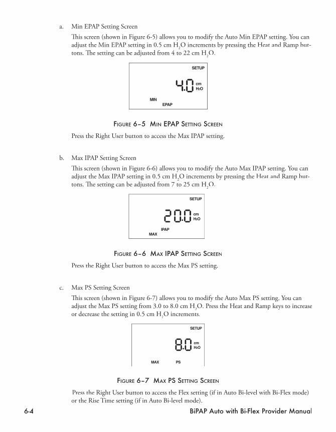
a. Min EPAP Setting Screen Th is screen (shown in Figure 6-5) allows you to modify the Auto Min EPAP setting. You can
adjust the Min EPAP setting in 0.5 cm H2O increments by pressing the Heat and Ramp but-tons. Th e setting can be adjusted from 4 to 22 cm H2O.
FIGURE 6–5 MIN EPAP SETTING SCREEN
Press the Right User button to access the Max IPAP setting.
b. Max IPAP Setting Screen Th is screen (shown in Figure 6-6) allows you to modify the Auto Max IPAP setting. You can
adjust the Max IPAP setting in 0.5 cm H2O increments by pressing the Heat and Ramp but-tons. Th e setting can be adjusted from 7 to 25 cm H2O.
FIGURE 6–6 MAX IPAP SETTING SCREEN
Press the Right User button to access the Max PS setting.
c. Max PS Setting Screen Th is screen (shown in Figure 6-7) allows you to modify the Auto Max PS setting. You can
adjust the Max PS setting from 3.0 to 8.0 cm H2O. Press the Heat and Ramp keys to increase or decrease the setting in 0.5 cm H2O increments.
FIGURE 6–7 MAX PS SETTING SCREEN
Press the Right User button to access the Flex setting (if in Auto Bi-level with Bi-Flex mode) or the Rise Time setting (if in Auto Bi-level mode).
BiPAP Auto with Bi-Flex Provider Manual 6-5
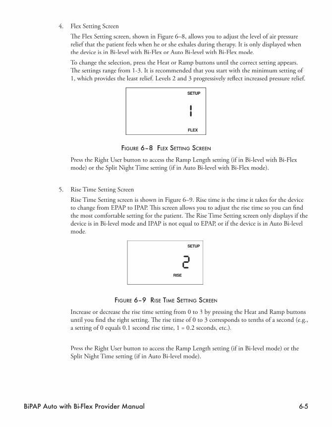
4. Flex Setting Screen Th e Flex Setting screen, shown in Figure 6–8, allows you to adjust the level of air pressure
relief that the patient feels when he or she exhales during therapy. It is only displayed when the device is in Bi-level with Bi-Flex or Auto Bi-level with Bi-Flex mode.
To change the selection, press the Heat or Ramp buttons until the correct setting appears. Th e settings range from 1-3. It is recommended that you start with the minimum setting of 1, which provides the least relief. Levels 2 and 3 progressively refl ect increased pressure relief.
FIGURE 6–8 FLEX SETTING SCREEN
Press the Right User button to access the Ramp Length setting (if in Bi-level with Bi-Flex mode) or the Split Night Time setting (if in Auto Bi-level with Bi-Flex mode).
5. Rise Time Setting Screen Rise Time Setting screen is shown in Figure 6–9. Rise time is the time it takes for the device
to change from EPAP to IPAP. Th is screen allows you to adjust the rise time so you can fi nd the most comfortable setting for the patient. Th e Rise Time Setting screen only displays if the device is in Bi-level mode and IPAP is not equal to EPAP, or if the device is in Auto Bi-level mode.
FIGURE 6–9 RISE TIME SETTING SCREEN
Increase or decrease the rise time setting from 0 to 3 by pressing the Heat and Ramp buttons until you fi nd the right setting. Th e rise time of 0 to 3 corresponds to tenths of a second (e.g., a setting of 0 equals 0.1 second rise time, 1 = 0.2 seconds, etc.).
Press the Right User button to access the Ramp Length setting (if in Bi-level mode) or the Split Night Time setting (if in Auto Bi-level mode).

BiPAP Auto with Bi-Flex Provider Manual6-6
6. Ramp Length Setting Screen Th e Ramp Length Setting screen, shown in Figure 6–10, allows you to change the ramp time.
FIGURE 6–10 RAMP LENGTH SETTING SCREEN
NOTE: The Ramp length setting screen only displays if the device is in Bi-level or Bi-level with Bi-Flex mode.
To change the ramp time, press the Heat and Ramp buttons until the correct time appears. Th e setting increases or decreases from 0 to 45 minutes in 5 minute increments. If you do not want ramp, set the time to zero.
Press the Right User button to access the ramp start pressure setting (if ramp length is between 5 and 45 minutes) or the Patient Disconnect setting (if ramp length is set to 0).
7. Ramp Start Pressure Setting Screen Th e Ramp Start Pressure Setting screen is shown in Figure 6–11.
NOTE: This screen only displays if the device is in Bi-level or Bi-level with Bi-Flex mode and the ramp length setting is greater than zero.
FIGURE 6–11 RAMP START PRESSURE SETTING SCREEN
To change the ramp starting pressure, press the Heat and Ramp buttons until the correct pressure appears. Th e setting increases or decreases in 0.5 cm H2O increments. Th e user can adjust the setting from 4 cm H2O to the EPAP pressure setting.
Press the Right User button to access the Patient Disconnect setting.
BiPAP Auto with Bi-Flex Provider Manual 6-7
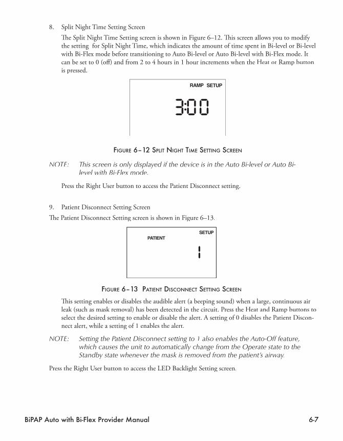
8. Split Night Time Setting Screen Th e Split Night Time Setting screen is shown in Figure 6–12. Th is screen allows you to modify
the setting for Split Night Time, which indicates the amount of time spent in Bi-level or Bi-level with Bi-Flex mode before transitioning to Auto Bi-level or Auto Bi-level with Bi-Flex mode. It can be set to 0 (off ) and from 2 to 4 hours in 1 hour increments when the Heat or Ramp button is pressed.
FIGURE 6–12 SPLIT NIGHT TIME SETTING SCREEN
NOTE: This screen is only displayed if the device is in the Auto Bi-level or Auto Bi-level with Bi-Flex mode.
Press the Right User button to access the Patient Disconnect setting.
9. Patient Disconnect Setting ScreenTh e Patient Disconnect Setting screen is shown in Figure 6–13.
FIGURE 6–13 PATIENT DISCONNECT SETTING SCREEN
Th is setting enables or disables the audible alert (a beeping sound) when a large, continuous air leak (such as mask removal) has been detected in the circuit. Press the Heat and Ramp buttons to select the desired setting to enable or disable the alert. A setting of 0 disables the Patient Discon-nect alert, while a setting of 1 enables the alert.
NOTE: Setting the Patient Disconnect setting to 1 also enables the Auto-Off feature, which causes the unit to automatically change from the Operate state to the Standby state whenever the mask is removed from the patient’s airway.
Press the Right User button to access the LED Backlight Setting screen.

BiPAP Auto with Bi-Flex Provider Manual6-8
10. LED Backlight Setting Screen Th e LED Backlight Setting screen is shown in Figure 6–14. Th is setting allows you to have the
control panel lights behind the buttons turned on or off while the airfl ow is turned on and the device is in the Operate state.
NOTE: The lights will always be on when the airfl ow is off and the device is in Standby.
FIGURE 6–14 LED BACKLIGHT SETTING SCREEN
To change the LED backlight setting, press the Ramp or Heat button until the correct setting ap-pears. 1 means the light is on, while 0 means the light is off .
Press the Right User button to access the Reset Session Counter screen.
14. Reset Session Counter Screen Th e Reset Session Counter screen is shown in Figure 6–15.
FIGURE 6–15 RESET SESSION COUNTER SETTING SCREEN
Th is screen displays the number of hours that the device delivered therapy to the patient. Th e screen allows you to reset the session counter. Resetting the session counter also resets the Th erapy Time Meter.
To erase the totals and go back to zero, press and hold the Ramp or Heat button. Th e ERASE icon displays on the screen. Hold the button down until the time changes to zero and the ERASE icon disappears. Th e NIGHTS icon also displays on this screen.

BiPAP Auto with Bi-Flex Provider Manual 6-9
6.2 CHANGING SETTINGS IN USER MODE
With the device in User mode, the patient is restricted to viewing the current pressure setting.
Th e patient can also view and change the following settings in User mode by pressing and holding the Heat or Ramp button while the device is in Standby:• Session counter (cannot be changed in User Mode)• Flex setting (when Bi-Flex is enabled at the Provider level)• FOSQ Questionnaire• Rise time (when in Bi-level mode and IPAP is not equal to EPAP or when in Auto Bi-level mode)• Ramp start pressure (when in Bi-level or Bi-level with Bi-Flex mode and ramp length is set be-
tween 5 and 45 minutes)• Patient disconnect• LED backlight
Additionally, the patient can change the Humidifi er (heat) setting by pressing and holding the Heat button to access the Humidifi er Setting screen.
See the BiPAP Auto with Bi-Flex User Manual for additional information.

BiPAP Auto with Bi-Flex Provider Manual6-10

BiPAP Auto with Bi-Flex Provider Manual 7-1
CHAPTER 7: ALERTS Th is chapter describes the device alerts, how to set them, and what corrective actions to take for the alert conditions.
7.1 INTRODUCTION Th e device provides three alert levels: high, medium, and low priority.
ALERT DESCRIPTION
High Priority These alerts require immediate operator response. The alert signal consists of a high priority sound. The display has the message ALERT at the top of the screen.
Medium Priority These alerts require prompt operator response. The alert signal consists of a medium priority sound. The display has the message ALERT at the top of the screen.
Low Priority These alerts require operator awareness. The alert signal consists of a low priority sound. The display has the message ALERT at the top of the screen.
Some audible alerts are self-cancellable. Th is means that the alert sound stops when the cause of the alert is corrected. See section 7.5 for detailed descriptions of the alert indicators and sounds.
7.1.1 OVERVIEW OF ALERT BEHAVIOR
Alert conditions are signalled by the device in two ways: a sound and a display message. Each signal type behaves diff erently depending on the type of alert.
7.1.1.1 ALERT SOUNDS BEHAVIOR 1. High Priority Sounds Th ere are two possible high priority sounds: • High Priority – Th e sound repeats a pattern of three beeps followed by a pause and then • High Priority – Th e sound repeats a pattern of three beeps followed by a pause and then • High Priority
two more beeps until a button is pressed. Th is pattern is indicated in Section 7.5 as • • • • •
• Continuous – An audible alert sounds continuously. Th is pattern is indicated in Section 7.5 as
BiPAP Auto with Bi-Flex Provider Manual7-2
2. Medium Priority Sound Th e medium priority sound repeats a pattern of beeps with a short interval between each beep
until the cause of the alert is corrected. Th is pattern is indicated in Section 7.5 as •• 3. Low Priority Sound Th e low priority sound repeats a pattern of beeps with a longer interval between each beep until a
button is pressed or until the cause of the alert is corrected. Th is pattern is indicated in Section 7.5 as • •
7.1.1.2 DISPLAY BEHAVIOR
For high, medium, and low priority alerts, the display shows ALERT and the name of the alert.
7.2 ALERTS Th e device has system, card, and patient alerts.
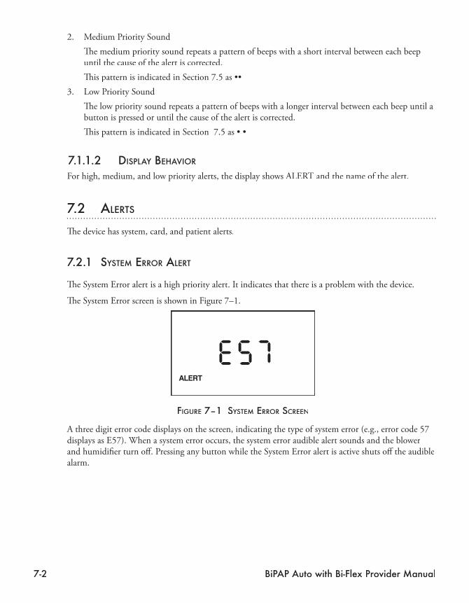
7.2.1 SYSTEM ERROR ALERT
Th e System Error alert is a high priority alert. It indicates that there is a problem with the device.
Th e System Error screen is shown in Figure 7–1.
FIGURE 7–1 SYSTEM ERROR SCREEN
A three digit error code displays on the screen, indicating the type of system error (e.g., error code 57 displays as E57). When a system error occurs, the system error audible alert sounds and the blower and humidifi er turn off . Pressing any button while the System Error alert is active shuts off the audible alarm.

BiPAP Auto with Bi-Flex Provider Manual 7-3
7.2.2 CARD ERROR ALERT
Th e Card Error alert is a medium priority alert. It indicates that a problem exists with the card inserted in the SmartCard connectivity slot. Removing the SmartCard automatically resets this alert.
Th e Card Error screen is shown in Figure 7–2.
FIGURE 7–2 CARD ERROR SCREEN
A three digit error code displays on the screen, indicating the type of card error (e.g., error code 57 dis-plays as C57). Th e SmartCard must be removed to exit this screen and return to the previous screen.
7.3 PATIENT DISCONNECT ALERT Figure 7–3 shows the Patient Disconnect alert screen.
FIGURE 7–3 PATIENT DISCONNECT ALERT SCREEN
Th e Patient Disconnect alert is a low priority alarm. If the Patient Disconnect alert is enabled, the alert occurs when the patient is disconnected from the device. See Chapter 6 for information on how to enable or disable the Patient Disconnect alert.
When a patient disconnect alert occurs, the PATIENT and ALERT icons fl ash on the display. Press any button to shut off the alert.
BiPAP Auto with Bi-Flex Provider Manual7-4
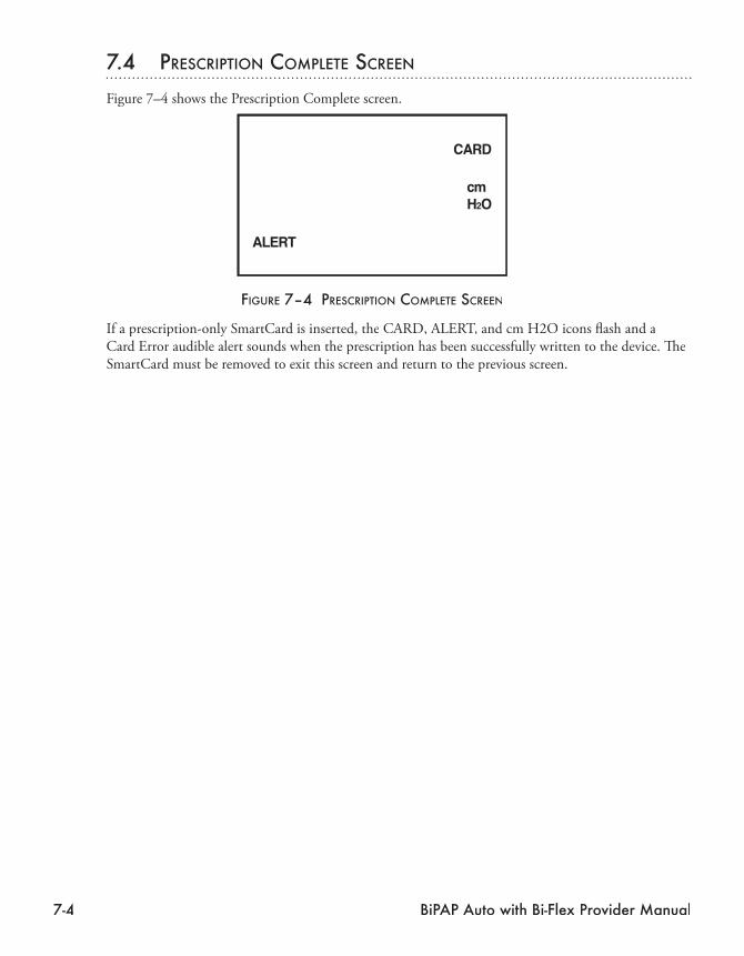
7.4 PRESCRIPTION COMPLETE SCREEN Figure 7–4 shows the Prescription Complete screen.
FIGURE 7–4 PRESCRIPTION COMPLETE SCREEN
If a prescription-only SmartCard is inserted, the CARD, ALERT, and ALERT, and ALERT cm H2O icons fl ash and a Card Error audible alert sounds when the prescription has been successfully written to the device. Th e SmartCard must be removed to exit this screen and return to the previous screen.
BiPAP Auto with Bi-Flex Provider Manual 7-5
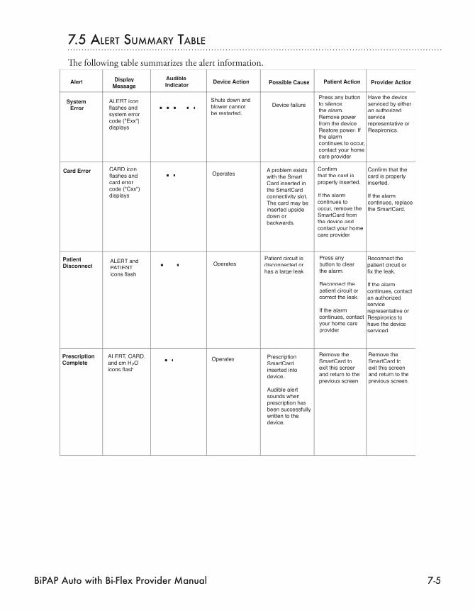
7.5 ALERT SUMMARY TABLE Th e following table summarizes the alert information.
System Error
Alert DisplayMessage
Audible Indicator
Device Action Possible Cause Patient Action Provider Action
ALERT icon T icon Tflashes and system error code ("Exx")displays
• • • • •Shuts down and blower cannot be restarted.
Device failure.Press any button to silence the alarm.Remove power from the device.Restore power. If the alarm continues to occur, contact your home care provider.
Have the deviceserviced by either an authorized service representative or Respironics.
Card Error CARD icon flashes and card error code ("Cxx")displays
• • Operates A problem exists with the SmartCard inserted in the SmartCard connectivity slot.The card may be inserted upside down or backwards.
Confirm that the card is properly inserted.
If the alarm continues to occur, remove the SmartCard from the device and contact your home care provider.
Confirm that the card is properly inserted.
If the alarm continues, replace the SmartCard.
Patient Disconnect
ALERT and T and TPATIENTicons flash
• •Patient circuit is disconnected or has a large leak.
Press anybutton to clear the alarm.
Reconnect the patient circuit or correct the leak.
If the alarm continues, contact your home care provider.
Reconnect the patient circuit or fix the leak.
If the alarm continues, contact an authorized service representative or Respironics to have the deviceserviced.
PrescriptionComplete
Operates Prescription SmartCard inserted into device.
Audible alertsounds whenprescription hasbeen successfullywritten to the device.
Remove theSmartCard toexit this screenand return to theprevious screen.
ALERT, CARD,T, CARD,Tand cm H2O icons flash
Operates
• • Remove theSmartCard toexit this screenand return to theprevious screen.

BiPAP Auto with Bi-Flex Provider Manual7-6

BiPAP Auto with Bi-Flex Provider Manual 8-1
CHAPTER 8: CLEANING AND MAINTENANCE
Th is chapter describes how to clean the device and its fi lters and how to maintain the unit.
8.1 CLEANING THE DEVICE
WARNING: To avoid electrical shock, always unplug the device power cord from the AC (wall outlet) or DC power source before cleaning the device.
CAUTION: Do not immerse the device in liquid or allow any liquid to enter the enclosure, inlet fi lter, or any opening.
WARNING: If you are using the device on multiple users, discard and replace the bacteria fi lter each time the device is used on a different person.
Unplug the device and clean the front panel and exterior of the enclosure as needed using a cloth dampened with water and a mild detergent. Allow the device to dry completely before plugging in the power cord.
Th e mask and tubing should be cleaned daily. For details on cleaning your mask and accessories, refer to the cleaning instructions packaged with the accessories.
CAUTION: Dirty inlet fi lters may cause high operating temperatures that may affect device performance. Regularly examine the inlet fi lters as needed for integrity and cleanliness.
8.2 CLEANING OR REPLACING THE INLET FILTERS
Th e device uses two removable fi lters at the air inlet. Th e gray foam fi lter is washable and reusable. Th e optional white ultra-fi ne fi lter is disposable. Under normal usage, clean the gray foam fi lter at least once every two weeks and replace it with a new one every six months.1. If the device is operating, stop the airfl ow by pressing the Start/Stop button. Disconnect the
device from the power source.2. Remove the fi lter cover by gently pressing down on the two latches on top of the fi lter cover (Fig-
ure 8–1).
FIGURE 8–1 REMOVING THE FILTER COVER
BiPAP Auto with Bi-Flex Provider Manual8-2
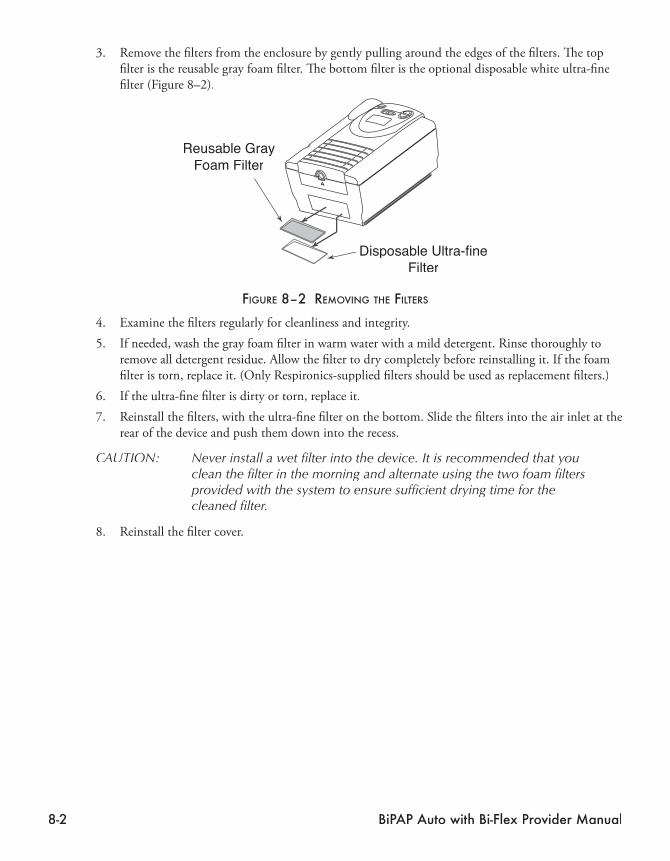
3. Remove the fi lters from the enclosure by gently pulling around the edges of the fi lters. Th e top fi lter is the reusable gray foam fi lter. Th e bottom fi lter is the optional disposable white ultra-fi ne fi lter (Figure 8–2).
Reusable GrayFoam Filter
Disposable Ultra-fineFilter
FIGURE 8–2 REMOVING THE FILTERS
4. Examine the fi lters regularly for cleanliness and integrity.5. If needed, wash the gray foam fi lter in warm water with a mild detergent. Rinse thoroughly to
remove all detergent residue. Allow the fi lter to dry completely before reinstalling it. If the foam fi lter is torn, replace it. (Only Respironics-supplied fi lters should be used as replacement fi lters.)
6. If the ultra-fi ne fi lter is dirty or torn, replace it.7. Reinstall the fi lters, with the ultra-fi ne fi lter on the bottom. Slide the fi lters into the air inlet at the
rear of the device and push them down into the recess.
CAUTION: Never install a wet fi lter into the device. It is recommended that you clean the fi lter in the morning and alternate using the two foam fi lters provided with the system to ensure suffi cient drying time for the cleaned fi lter.
8. Reinstall the fi lter cover.
BiPAP Auto with Bi-Flex Provider Manual 8-3
8.3 CLEANING AND DISINFECTION FOR MULTIPLE USERS If you are using the device on multiple users, complete the following steps to clean and disinfect the unit before each new user.1. Unplug the device before disinfecting.2. Disinfect the outside of the unit only. Use a cloth with one of the following cleaning agents to
clean the exterior of the device: hydrogen peroxide, 3%; 100% isopropyl alcohol; vinegar, 5% acidity; water; or household chlorine bleach, 5.25% sodium hypochloride, 1 to 5 part reduction with water.
3. Allow the device to dry completely before plugging in the power cord.
WARNING: Do not immerse the device in liquid or allow any liquid to enter the enclosure, inlet fi lter, or any opening. This may result in equipment damage.
WARNING: If you are using the device on multiple users, discard and replace the bacteria fi lter everyevery time the device is used on a different person.every time the device is used on a different person.every
8.4 MAINTENANCE
WARNING: Electrical cords or cables should be periodically inspected for damage or signs of wear.
See the BiPAP Auto with Bi-Flex Service ManualBiPAP Auto with Bi-Flex Service ManualBiPAP Auto with Bi-Flex for recommended periodic maintenance.

BiPAP Auto with Bi-Flex Provider Manual8-4

BiPAP Auto with Bi-Flex Provider Manual 9-1
CHAPTER 9: ADDING SUPPLEMENTAL OXYGEN Oxygen may be added at the mask connection. Please note the warnings listed below when using oxygen with the device.
WARNING: The oxygen supply must comply with local regulations for oxygen use.
WARNING: When using oxygen with this system, a Respironics Pressure Valve (Part number 302418) must be placed in-line with the patient circuit. Place the valve in-line with the patient circuit and connect the oxygen as shown here:
To Controlled
Oxygen Source
O2 Enrichment Enrichment
Attachment
FIGURE 9–1 USING THE RESPIRONICS PRESSURE VALVE
WARNING: Oxygen should be administered only on the order of a physician.
WARNING: Supplemental oxygen should not be added to the breathing circuit by placing the source where the gas will be entrained through the inlet fi lter on the rear of the device.
WARNING: Continuous patient monitoring is recommended while administering oxygen. Patient monitoring should consist of, at a minimum, patient observation and pulse oximetry. Arterial blood gas measurements should be used when necessary.
WARNING: If administering fi xed-fl ow supplemental oxygen, the oxygen concen- tration may not be constant. The inspired oxygen concentration will vary, depending on the IPAP and EPAP settings, patient breathing pat- tern, and the leak rate. Substantial leaks around the mask may reduce the inspired oxygen concentration to less than the expected concentra- tions shown in section 9.2. Appropriate patient monitoring should be implemented.
WARNING: When using oxygen with this system, turn the device on before turn- ing the oxygen on. Turn the oxygen off before turning the device off. This will prevent oxygen accumulation in the device.
BiPAP Auto with Bi-Flex Provider Manual9-2
WARNING: Oxygen accelerates fi res. Keep the device and the oxygen container away from heat, open fl ames, any oily substance, or other sources of ignition. Do not smoke in the area near the device or the oxygen.Do not smoke in the area near the device or the oxygen.Do not
9.1 ADDING SUPPLEMENTAL OXYGEN Th e delivered oxygen concentration varies with changes in fl ow in the circuit. Th e following may have an impact on oxygen concentration:• Pressure settings• Patient Tidal Volume• Peak Inspiratory Flow• I:E Ratio• Respiratory rate• Circuit leak rate• Oxygen fl ow rate
To add oxygen to the circuit, the oxygen supply must comply with the local regulations for medi-cal oxygen. Th e oxygen fl ow into the oxygen valve cannot exceed 15 L/min and the pressure cannot exceed 50 psi.
9.2 SUPPLEMENTAL OXYGEN CONCENTRATIONS Figures 9–2 and 9–3 illustrate the potential range of oxygen concentration available to the patient at a given tidal volume, supplemental oxygen fl ow, and pressure setting. Th ese fi gures represent bench test results without inadvertent mask leaks when oxygen is administered at the mask. Substantial leaks around the mask may reduce the expected oxygen concentration to below the levels shown in Figures 9–2 and 9–3. Th is guideline may be used as a starting point for initiating oxygen therapy. Oxygen fl ow should be gradually adjusted until the patient’s oxygen needs are adequately met.
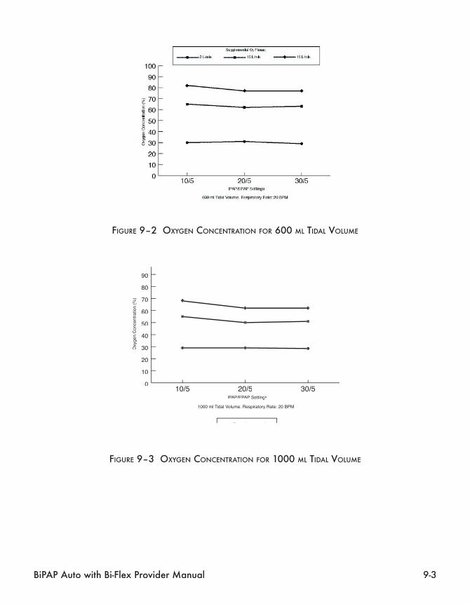
BiPAP Auto with Bi-Flex Provider Manual 9-3
FIGURE 9–2 OXYGEN CONCENTRATION FOR 600 ML TIDAL VOLUME
0
10
20
30
40
50
60
70
80
90
30/520/510/5
Oxy
gen
Con
cent
ratio
n (%
)
IPAP/EPIPAP/EPIP APAP/EPAPAP/EP Settings
1000 ml Tidal Volume. Respiratory Rate: 20 BPMidal Volume. Respiratory Rate: 20 BPMidal V
Supplemental
FIGURE 9–3 OXYGEN CONCENTRATION FOR 1000 ML TIDAL VOLUME

BiPAP Auto with Bi-Flex Provider Manual9-4
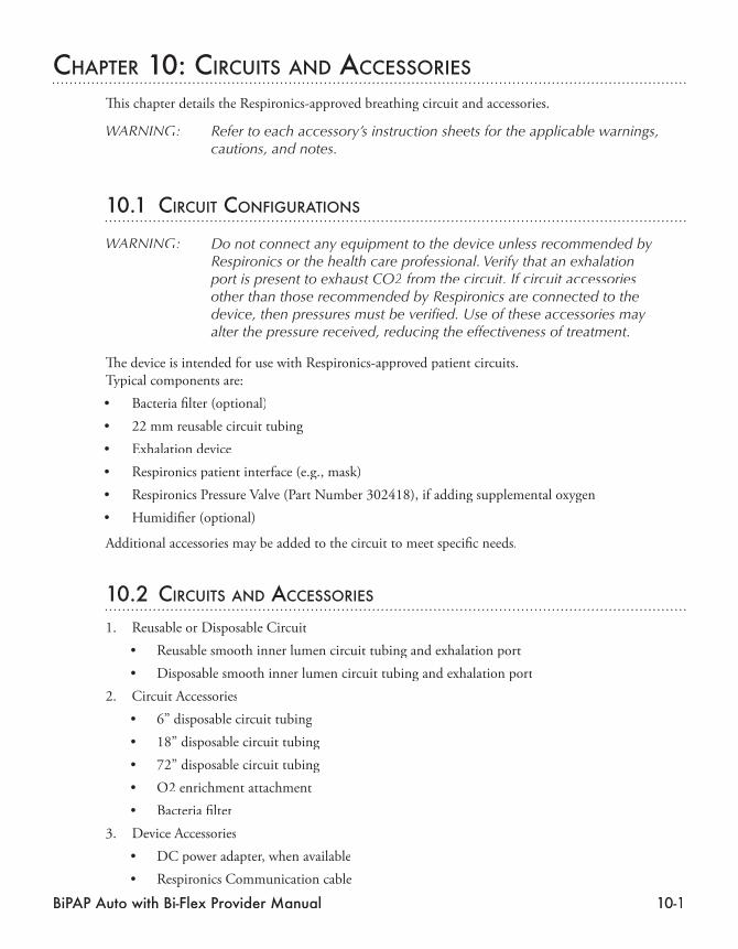
BiPAP Auto with Bi-Flex Provider Manual 10-1
CHAPTER 10: CIRCUITS AND ACCESSORIES
Th is chapter details the Respironics-approved breathing circuit and accessories.
WARNING: Refer to each accessory’s instruction sheets for the applicable warnings, cautions, and notes.
10.1 CIRCUIT CONFIGURATIONS
WARNING: Do not connect any equipment to the device unless recommended by Respironics or the health care professional. Verify that an exhalation port is present to exhaust CO2 from the circuit. If circuit accessories other than those recommended by Respironics are connected to the device, then pressures must be verifi ed. Use of these accessories may alter the pressure received, reducing the effectiveness of treatment.
Th e device is intended for use with Respironics-approved patient circuits. Typical components are:• Bacteria fi lter (optional)• 22 mm reusable circuit tubing• Exhalation device• Respironics patient interface (e.g., mask)• Respironics Pressure Valve (Part Number 302418), if adding supplemental oxygen• Humidifi er (optional)
Additional accessories may be added to the circuit to meet specifi c needs.
10.2 CIRCUITS AND ACCESSORIES 1. Reusable or Disposable Circuit
• Reusable smooth inner lumen circuit tubing and exhalation port• Disposable smooth inner lumen circuit tubing and exhalation port
2. Circuit Accessories• 6” disposable circuit tubing• 18” disposable circuit tubing• 72” disposable circuit tubing• O2 enrichment attachment• Bacteria fi lter
3. Device Accessories• DC power adapter, when available• Respironics Communication cable
BiPAP Auto with Bi-Flex Provider Manual10-2
10.3 MASKS, EXHALATION PORTS, AND RELATED ACCESSORIES 1. Masks
• Respironics mask with built-in exhalation port or Respironics mask with separate exhalation device
2. Accessories• Disposable headgear• Reusable headgear• Chin strap
10.4 HUMIDIFIERS 1. Respironics REMstar Heated humidifi er2. Respironics REMstar Integrated humidifi erWhen using other humidifi ers, verify that the delivered pressure is correct and that proper therapy is
being delivered.
NOTE: Refer to the humidifi er’s instructions for information on how to set up the device with the humidifi er.
10.5 SOFTWARE Respironics Encore® Pro Data Management software for reading compliance data and setting up a prescription via a SmartCard.

BiPAP Auto with Bi-Flex Provider Manual 11-1
CHAPTER 11: SPECIFICATIONS
ENVIRONMENTAL
Operating Storage
Temperature 41° F to 95° F -4° F to 140° F
Relative Humidity 15 to 95% 15 to 95% (non-condensing) (non-condensing)
Atmospheric Pressure 83 to 102kPa (5600 feet to sea level)
PHYSICAL
Dimensions: 9.75” L x 6.625” W x 4.4” H
Weight: Less than 7 lbs.
ELECTRICAL
AC Voltage Source: 100 to 240 V, 50/60 Hz
DC Voltage Source: 24 V (when operated with the external DC power adapter accessory)
AC Current: 1.25 A maximum
DC Current: 3.0 A maximum
Protection against electric shock: Class II
Degree of protection against electric shock: Type BF Applied Part
Degree of protection against harmful ingress of water: Device: Ordinary Equipment, IPX0 AC Power Supply (Reorder number 1012832): Drip Proof, IPX1 DC Power Adapter (when available): Drip Proof, IPX1
Modes of Operation: Continuous
Electromagnetic Compatibility: Th e device meets the requirements of EN 60601-1-2, second edition (2001).
Fuses: Th ere are no user-replaceable fuses.

BiPAP Auto with Bi-Flex Provider Manual11-2
PRESSURE
Output: 4 to 25 cm H2O
Pressure Stability: 4.0 to 10.0 cm H2O (±0.5 cm H2O) >10.0 to 25.0 cm H2O (±1.0 cm H2O)
Measured in accordance with EN ISO 17510-1 @ 6.6, 13.2, and 20 cm H2O @ 500 ml with BPM set to 10, 15 & 20 BPM @ 23° C (±2.0° C), 50% RH (±5%), and an atmospheric pressure of 101.54 kPascals.
Sound Pressure Level: <45 dB(A)
Measured in accordance with EN ISO 17510-1 @ 10 cm H2O at the patient circuit. Th is measure-ment applies to the BiPAP Auto with Bi-Flex with or without the optional REMstar Heated Humidi-fi er.
Maximum Flow: <35 LPM
Measured in accordance with EN ISO 17510-1 @ 8, 16.5, and 25 cm H2O @ 500 ml with BPM set to 10, 15 & 20 BPM @ 23° C (±2.0° C), 50% RH (±5%), and an atmospheric pressure of 101.54 kPascals.
CONTROL ACCURACY
Parameter Range Accuracy
IPAP 4 to 25 cm H2O ± 1.5 cm H2O from static setpoint*/****
EPAP 4 to 25 cm H2O ± 1.5 cm H2O from static setpoint*/****
Ramp Duration 0 to 45 minutes ± 10% of setting
Rise Time 0 to 3** ± 25%***
* Dynamic pressure accuracy is measured at the patient end of the circuit with a Whisper Swivel II and varying fl ow conditions.
** Th e range of values correspond to tenths of seconds (0 to 3 corresponds to 0.1 to 0.4 seconds).
*** Measured at the patient end of circuit with a Whisper Swivel II exhalation device and no patient fl ow.
**** Measured in accordance with EN ISO 17510-1 @ 4, 8, 16.5, and 25 cm H2O @ 500 ml with BPM set to 10, 15 & 20 BPM @ 23° C (±2.0° C), 50% RH (±5%), and an atmospheric pressure of 101.54 kPascals.
DISPOSAL
When necessary, dispose of the device and accessories in accordance with local regulations.

BiPAP Auto with Bi-Flex Provider Manual 11-3
PRESSURE DROP VERSUS FLOW FOR PATIENT CIRCUITS Th e device automatically compensates for pressure drops associated with a 6-foot smooth bore tube. Additional pressure drop will occur when restrictive elements are added to the patient circuit. Th e following graph shows the additional pressure drop when adding: 1. a bacteria fi lter; 2. a bacteria fi lter and a Respironics humidifi er.
NOTE: Always use a manometer to verify patient mask pressure.
FIGURE 11–1 PRESSURE DROP VERSUS FLOW FOR PATIENT CIRCUITS

BiPAP Auto with Bi-Flex Provider Manual11-4

BiPAP Auto with Bi-Flex Provider Manual A-1
APPENDIX A EMC INFORMATION
GUIDANCE AND MANUFACTURERʼS DECLARATION - ELECTROMAGNETIC EMISSIONS
Th is device is intended for use in the electromagnetic environment specifi ed below. Th e user of this device should make sure it is used in such an environment.
EMISSIONS TEST COMPLIANCE ELECTROMAGNETIC ENVIRONMENT - GUIDANCE
RF emissionsCISPR 11
Group 1 The device uses RF energy only for its internal function. Therefore, its RF emissions are very low and are not likely to cause any interference in nearby electronic equipment.
RF emissionsCISPR 11
Class B The device is suitable for use in all establishments, including domestic establishments and those directly connected to the public low-volt-age power supply network.
Harmonic emissionsIEC 61000-3-2
Class A
Voltage fl uctuations/Flicker emissionsIEC 61000-3-3
Complies

BiPAP Auto with Bi-Flex Provider ManualA-2
GUIDANCE AND MANUFACTURERʼS DECLARATION - ELECTROMAGNETIC IMMUNITY
Th is device is intended for use in the electromagnetic environment specifi ed below. Th e user of this device should make sure it is used in such an environment.
IMMUNITY TEST IEC 60601 TEST LEVEL
COMPLIANCE LEVEL ELECTROMAGNETIC ENVIRONMENT -
GUIDANCE
Electrostatic Discharge (ESD)
IEC 61000-4-2
+6 kV contact
+8 kV air
+6 kV contact
+8 kV air
Floors should be wood, concrete or ceramic tile. If fl oors are covered with synthetic material, the relative humidity should be at least 30%.
Electrical fast Transient/burst
IEC 61000-4-4
+2 kV for power supply lines
+1 kV for input-out-put lines
+2 kV for supply mains
+1 kV for input/out-put lines
Mains power quality should be that of a typical home or hos-pital environment.
SurgeIEC 61000-4-5
+1 kV differential mode
+2 kV common mode
+1 kV differential mode
+2 kV for common mode
Mains power quality should be that of a typical home or hos-pital environment.
Voltage dips, short interruptions and voltage variations on power supply input lines
IEC 61000-4-11
<5% UT
(>95% dip in UT) for 0.5 cycle 40% UT
(60% dip in UT) for 5 cycles70% UT (30% dip in T (30% dip in T
UT) for 25 cycles<5% UT (>95% dip T (>95% dip T
in UT) for 5 sec
<5% UT
(>95% dip in UT) for 0.5 cycle 40% UT
(60% dip in UT) for 5 cycles70% UT (30% dip in T (30% dip in T
UT) for 25 cycles<5% UT (>95% dip T (>95% dip T
in UT) for 5 sec
Mains power quality should be that of a typical home or hos-pital environment.
NOTE: UT is the a.c. mains voltage prior to application of the test level.T is the a.c. mains voltage prior to application of the test level.T

BiPAP Auto with Bi-Flex Provider Manual A-3
GUIDANCE AND MANUFACTURERʼS DECLARATION - ELECTROMAGNETIC IMMUNITY
Th is device is intended for use in the electromagnetic environment specifi ed below. Th e user of this device should make sure it is used in such an environment.
IMMUNITY TEST IEC 60601 TEST LEVEL
COMPLIANCE LEVEL
ELECTROMAGNETIC ENVIRONMENT -GUIDANCE
Power frequency (50/60 Hz) magnetic fi eld
IEC 61000-4-8
+6 kV contact
+8 kV air
+6 kV contact
+8 kV air
Floors should be wood, concrete or ceramic tile. If fl oors are covered with synthetic mate-rial, the relative humidity should be at least 30%.
Conducted RFIEC 61000-4-6
Radiated RFIEC 61000-4-3
3 Vrms150 kHz to 80 MHz
3 V/m80 MHz to 2.5 GHz
3 Vrms
3 V/m
Portable and mobile RF communications equipment should be used no closer to any part of the device, including cables, than the recommended separation distance calculated from the equation applicable to the frequency of the transmitter.
Recommended separation distanced = 1.2 P
d = 1.2 P 80 MHz to 800 MHzd = 2.3 P 800 MHz to 2.5 GHz
where P is the maximum output power rating of the transmitter in watts (W) according to the transmitter manufacturer and d is the recom-mended separation distance in meters (m).
Field strengths from fi xed RF transmitters, as determined by an electromagnetic site sur-veyaveyavey , should be less than the compliance level in each frequency range.b
Interference may occur in the vicinity of equipment marked with the following symbol:
NOTE 1 At 80 MHz and 800 MHz, the higher frequency range applies.NOTE 2 These guidelines may not apply in all situations. Electromagnetic propagation is affected by absorption and refl ection from structures, objects, and people. a Field strengths from fi xed transmitters, such as base stations for radio (cellular/cordless) telephones and land
mobile radios, amateur radio, AM and FM radio broadcast and TV broadcast cannot be predicted theoreti-cally with accuracy. To assess the electromagnetic environment due to fi xed RF transmitters, an electromag-netic site survey should be considered. If the measured fi eld strength in the location in which the device is used exceeds the applicable RF compliance level above, the device should be observed to verify normal operation. If abnormal performance is observed, additional measures may be necessary, such as re-orienting or relocating the device.
b Over the frequency range 150 kHz to 80 MHz, the fi eld strengths should be less than 3 V/m.

BiPAP Auto with Bi-Flex Provider ManualA-4
RECOMMENDED SEPARATION DISTANCES BETWEEN PORTABLE AND MOBILE RF COMMUNICATIONS EQUIPMENT AND THIS DEVICE
Th e device is intended for use in an electromagnetic environment in which radiated RF disturbances are controlled. Th e customer or the user of this device can help prevent electromagnetic interference by maintaining a minimum distance between portable and mobile RF communications equipment (transmitters) and this device as recommended below, according to the maximum output power of the communications equipment.
RATED MAXIMUM POWER OUTPUT OF
TRANSMITTER
W
SEPARATION DISTANCE ACCORDING TO FREQUENCY OF TRANSMITTER M
150 KHZ TO 80 MHZ
d = 1.2 P
80 MHZ TO 800 MHZ
d = 1.2 P
800 MHZ TO 2.5 GHZ
d = 2.3 P
0.01 0.12 0.12 0.23
0.1 0.38 0.38 0.73
1 1.2 1.2 2.3
10 3.8 3.8 7.3
100 12 12 23
For transmitters rated at a maximum output power not listed above, the recommended separation distance d in meters (m) can be estimated using the equation applicable to the d in meters (m) can be estimated using the equation applicable to the dfrequency of the transmitter, where P is the maximum output power rating of the transmit-ter in watts (W) according to the transmitter manufacturer.Note 1: At 80 MHz and 800 MHz, the separation distance for the higher frequency range applies.Note 2: These guidelines may not apply in all situations. Electromagnetic propagation is affected by absorption and refl ection from structures, objects, and people.

LIMITED WARRANTY Respironics, Inc. warrants that the device shall be free from defects of workmanship and materials and will perform in accordance with the product specifi cations for a period of two (2) years from the date of sale by Respironics, Inc. to the dealer. If the product fails to perform in accordance with the product specifi cations, Respironics, Inc. will repair or replace – at its option – the defective material or part. Respironics, Inc. will pay customary freight charges from Respironics, Inc. to the dealer location only. Th is warranty does not cover dam-age caused by accident, misuse, abuse, alteration, and other defects not related to material or workmanship.
Respironics, Inc. disclaims all liability for economic loss, loss of profi ts, overhead, or conse-quential damages which may be claimed to arise from any sale or use of this product. Some states do not allow the exclusion or limitation of incidental or consequential damages, so the above limitation or exclusion may not apply to you.
Th is warranty is given in lieu of all other express warranties. In addition, any implied war-ranties – including any warranty of merchantability or fi tness for the particular purpose – are limited to two years. Some states do not allow limitations on how long an implied warranty lasts, so the above limitation may not apply to you. Th is warranty gives you specifi c legal rights, and you may also have other rights which vary from state to state.
To exercise your rights under this warranty, contact your local authorized Respironics, Inc. dealer or contact Respironics, Inc. at:
1001 Murry Ridge LaneMurrysville, Pennsylvania 15668-8550
1-724-387-4000

1023859HM 7/6/05