Embed Size (px)
Citation preview
17175 JUNE 1982
RESPONSE OF FRICTION DAMPED
BRACED FRAMES
By Avtar S. Pall1 and Cedric Marsh2, Members, ASCE
ABSTRACT: A new concept of aseismic design for steel framed buildings is proposed. By providing sliding friction devices in the bracing system of the framed buildings, their earthquake resistance and damage control potential can be considerably enhanced. During severe earthquake excitations, the friction device slips and a large portion of the vibrational energy is dissipated mechanically in friction rather than inelastic yielding of the main structural components. Results of inelastic time-history dynamic analysis show superior performance of the friction damped braced steel frames when compared to computed responses of other structural framing systems. The proposed friction devices act, in effect, both as safety valves and structural dampers. The device may also be conveniently incorporated in existing framed buildings to upgrade their earthquake resistance.
INTRODUCTION
Severe ground shaking induces lateral inertial forces on buildings, causing them to sway back and forth with an amplitude proportional to the energy fed in. If a major portion of this energy can be consumed during building motion, the seismic response can be considerably improved. The manner in which this energy is consumed in the structure determines the level of damage.
1 Project Engr., The SNC Group, 1 -Complex Desjardins, Montreal, Quebec, Canada, 2 Prof., Centre for Building Studies, Concordia Univ., Montreal, Quebec, Canada. Note.-Discussion open until November 1, 1982. To extend the closing date one month, a written request must be filed with the Manager of Technical and Professional Publications, ASCE. Manuscript was submitted for review for possible publication on May 20, 1981. This paper is part of the Journal of the Structural Division, Proceedings of the American Society of Civil Engineers, CASCE, Vol. 108, No. ST6, June, 1982. ISSN 0044-8001/82/0006-1313/$01.00.
In general, all current methods of aseismic design place reliance on the ductility of the structural elements, i.e., ability to dissipate energy while undergoing inelastic deformations causing bending, twisting, and cracking. This assumes some permanent damage, in some cases just short of collapse, but the primary and secondary damage may be as economically significant as the collapse of the structure. If a major portion of the seismic energy can be dissipated mechanically, the response of the structure can be controlled without structural damage. This paper describes a novel structural system for steel framed buildings in which a large amount of seismic energy is extracted by providing an inexpensive sliding friction device in the steel braces of the structure. Inelastic time-history dynamic analysis has been used to study the seismic response of the proposed structural system. The results of the analyses, when compared with the computed response for a similar moment resisting frame and a braced moment resisting frame, show the superior performance of the friction damped braced frame. In this system, main structural elements remain elastic, without damage, or at least the onset of inelasticity is delayed to be available during catastrophic conditions. The friction device acts as a structural damper to control the amplitude and as a safety valve to limit the forces exerted.
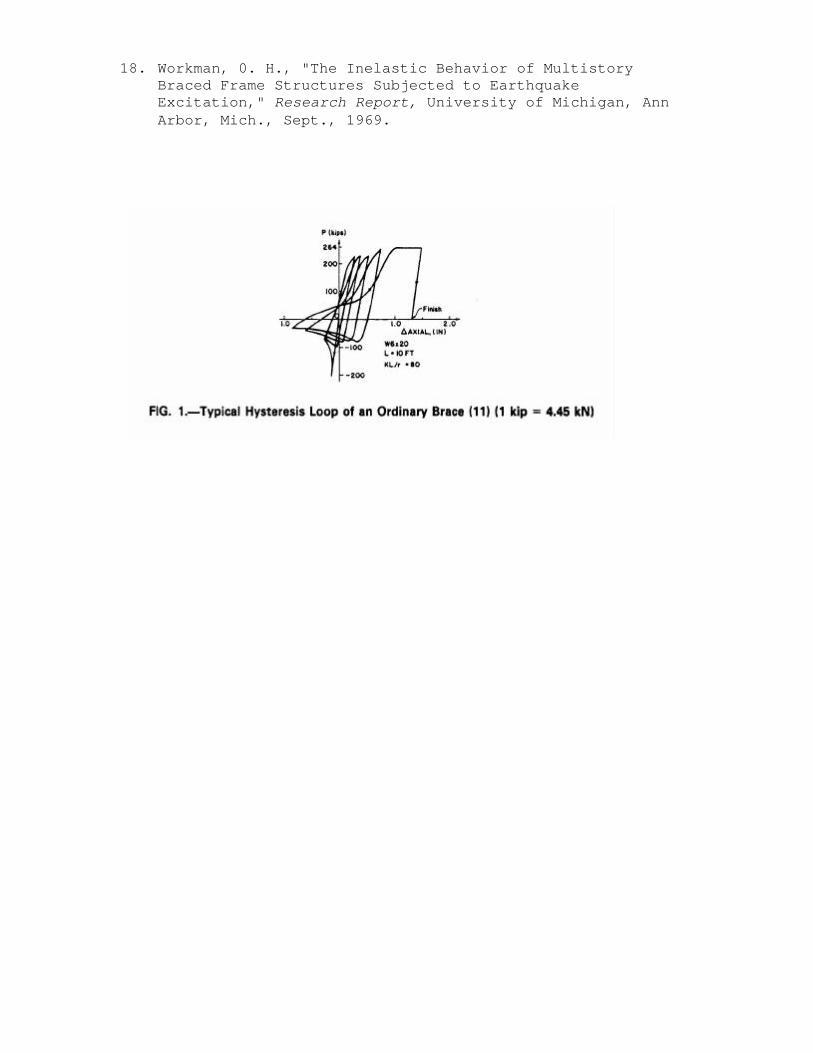
EXIST1NG STRUCTURAL SYSTEMS Braced steel frames are known to be economical and are effective in controlling lateral deflections due to wind and moderate earthquakes; but during major earthquakes, these structures do not perform well. Firstly, being stiffer, they tend to invite higher seismic forces, and secondly, their energy dissipation capacity is very much limited, due to the pinched hysteretic behavior of the braces (1,11,12,17). A typical hysteresis loop of a brace is shown in Fig. 1 (11). Energy dissipation is poor in structures with pinched or deteriorating hysteresis loops and are viewed with suspicion for earthquake resistance. The performance is still poorer when the brace is designed to be effective only in tension. A tension brace stretches during a severe shock and buckles in compression during reversal of load. On the next application of load in the same direction, this elongated brace is not effective even in tension until it is taut again and is being stretched further. As a result, energy dissipation degrades very quickly. Moment resisting frames are favored for, their earthquake resistance capability because they have stable ductile behavior under repeated reversing loads. This preference is reflected in various seismic codes (4,15,16) by assigning
lower lateral forces. However, these structures are very flexible and it is often economically difficult to develop enough stiffness to control story drifts and deflections to prevent nonstructural damage. Moreover, because of their greater deflection, the structural stability is affected by the P-? factor, which can be significant. Recent earthquakes have demonstrated the need for stiffer structures, and a strong interest has grown in the past few years (1,2,11,12,13,14,17) to develop structural systems which combine the ductile behavior of the moment resisting frame and the stiffness of a braced frame. In Japan, designers often employ braced moment resisting frames in which the brace is designed to carry only a portion of the lateral load (12). An eccentric braced frame (11,13,14) is another step in this direction. In this method, the brace joints are eccentric, to force the beams into inelastic action to dissipate more energy. After a major earthquake, large inelastic deformations must be expected at all floors of a structure. Although the structure is saved from total collapse, the main beams are sacrificed and an actual structure would need major repairs or replacement.
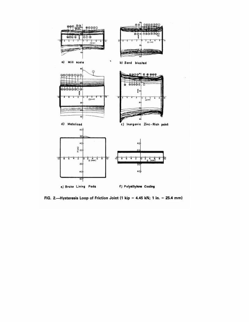
FRICTI0N DAMPED BRACED FRAME Logically it seems preferable to find some alternative source of energy dissipation to protect the main structural members from damage. Of all the methods available to extract kinetic energy from a moving body, the most widely adopted is undoubtedly the friction brake. Several static and dynamic tests on different faying surface treatments were conducted under repeated reversals of loads (7,8,9). Hysteresis loops of slip joints clamped together by high tension 1/2 in. (12.7mm) diameter high strength bolts (ASTM A325) are shown in Fig. 2. Of all of them, a heavy duty brake lining pad, inserted between the sliding steel surfaces, gave the best results. The performance is reliable, repeatable, and the hysterisis loops are rectangular with negligible fade over many more cycles of reversals than are encountered in successive earthquakes. Much greater quantities of energy can be disposed of in friction than by any method that involves damaging process of yielding of materials. Similar to automobiles, the motion of vibrating buildings is slowed down by braking rather than breaking. In the proposed structural system, each bracing in the moment resisting frame is provided with a friction device. The device is designed not to slip under normal service loads and moderate earthquakes. During severe seismic excitations, the device slips at a predetermined load, before yielding occurs in the other structural elements of the frame. Slippage in the device then provides a mechanism for the dissipation of energy by means of friction. As the braces then carry a constant load, the remaining loads are carried by the moment
resisting frame. In this manner, redistribution of forces takes place between successive stories, forcing all the braces to slip and participate in the process of energy dissipation. Such a modified structure combines the following characteristics:
1. It behaves like a braced frame structure during service load conditions, including wind and moderate earthquakes and possesses sufficient stiffness to control deflections. 2. Its flexibility increases as the device slips during extreme earthquake excitations resulting in prolonged effective periods of oscillation and thus, in general, reduced invitation to seismic forces. 3. It dissipates large amounts of energy in friction during slipping, thereby avoiding, or at least delaying, the yielding of main structural elements.
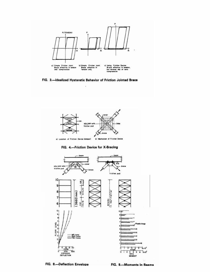
Brace with Friction Device.-A friction joint with slotted holes can be used to slip in tension and compression provided the brace is designed not to buckle in compression up to the slip load value. Hysteretic behavior of such a joint is shown in Fig. 3(a). Friction joints which slip at a high load in tension.and at a low load in compression, before the brace buckles, are also conceivable.
More often, the braces are quite slender and are designed to effective in tension only, in which case the friction joint slips in tensiot but will not slip back during reversal of load. In the subsequent cycle, the brace will not slip again until it is stretched beyond the previous elongated length, thus offering very little energy dissipation. Hysteretic behavior of such a friction joint is shown in Fig. 3(b). The preceding problem can be solved by connecting the X-bracings to a special mechanism which is located at the crossing of the two braces, as shown in Fig. 4(a). The general mechanism of the device is shown in Fig. 4(b). When tension in one of the braces forces the joint to slip, it activates the four links which force the joint in the other brace to slip simultaneously. In this manner, energy is dissipated in both the braces in each half cycle, which reciprocates in the next half cycle. Moreover, in each cycle, the mechanism brings the connection back and is ready to participate in future excursions. Hysteretic behavior of this joint is shown in Fig. 3(c). It is seen that energy dissipation of this brace is comparable with that of an ordinary friction joint used with braces which can carry compression. Fig. 5 shows details of a mechanism suitable for K-bracings. Many more variations are possible to suit particular needs. Friction devices can be used in any configuration of the bracing system. Some of the possible arrangements of bracings are shown in Fig. 6. Friction joints may be used between the
abutting columns of the two braced frames, as shown in Fig. 6(h). This concept is similar to the one proposed for concrete shear walls (5-10). Friction joints also may be used with advantage in connecting preassembled infill panels or curtain walls, which act as bracing elements to the frame. Furthermore, the device can be conveniently incorporated in ex isting framed buildings to upgrade their earthquake resistance. Optimum Slip Load.-The seismic response of a structure is determined by the amount of energy fed in and energy dissipated. The optimum seismic response, therefore, consists of minimizing the difference between the input energy and energy dissipated. The input energy basically is dependent on the natural period of the structure and the dynamic characteristics of the ground motion. It can be controlled to a certain extent by avoiding the phenomenon of resonance or quasiresonance by modifying the dynamic characteristics of the structure relative to the forcing motion. This is effectively possible in ground motions of narrow band characteristics. Since the future ground motion characteristics, associated with uncertainties generated by soil structure interaction, are highly erratic in nature, control of the input energy alone is not reliable. However, in friction damped braced frames, the period of the structure is -influenced by the slip load of the brace and varies with the amplitude of the oscillations, i.e. severity of the earthquake motion. Resonance of the structure is, therefore, more difficult to establish. The energy dissipation in the brace is proportional to the product of slip load and the slip travel during each excursion. For very high slip loads, the energy dissipation in friction will be zero, as there will be no slip If the slip load is very low, the amount of energy dissipation again will be negligible. Between these extremes, there is an intermediate value to give the maximum energy dissipation. Softening of the structure due to slipping of the braces can mean an invitation to higher or lower seismic forces, depending on its relation to the frequency content of the ground motion. The beneficial effects of energy dissipation must be combined with the effect of the altered period of vibration on the energy input which may be positive or negative. By the proper selection of the slip load, it is therefore possible to "tune" the response of the structure to an optimum value. EXAMPLE ANALYSIS To demonstrate the influence of the friction device on the seismic response, and to compare the results with alternate structural systems, a family of three 10 story frames, as
shown in Fig. 7, was chosen for analysis. Included were (1) Moment resisting (MR) frame; (2) braced moment resisting (BMR) frame; and (3) friction damped braced (FDB) frame.
The dimensions, member sizes, and other properties of all the moment resisting frames and braces are the same as used by Workman (18). Equal mass was assigned to all the floors of the three frames.
Inelastic time-history dynamic analysis was carried out using computer program "Drain-2D," developed at the University of California (3). This program consists of series of subroutines which carry out a step by step integration of the dynamic equilibrium equations using a constant acceleration algorithm within any time step. The earthquake record of El Centro 1940 (N.S. component) was used in these studies as it produces relatively symmetric-type cyclic excitations. It is known that different earthquake records, even though of the same intensifies, give widely varying structural responses, and results obtained using a single record may not be conclusive. However, it is sufficient to display the relative perforinance of different structural systems. The excitations used were scaled by a factor of 1 and 1.5 to give peak ground accelerations of 0.32 g and 0.48 g, respectively. To save computation costs, the analyses were conducted for a duration of only the first seven seconds, which includes the most severe motion, followed by zero acceleration for three seconds to allow the structure to come to rest. An integration time step of 0.01 sec was used in all the analyses. Flexural and axial deformations were considered. Interaction between axial force and moments for columns, and P-? effect were taken into account by including the geometric stiffness based on the axial force under static loads. Ordinary braces were assumed to yield in tension and buckle in compression, while the hysteretic behavior of the friction damped brace was modeled as shown in Fig. 3(c). Zero viscous damping was considered in all the analyses. Rigid foundations were assumed and soil structure interaction was neglected. Also, analyses for the friction damped braced frame were made for different slip loads of the device to obtain the optimum value.
RESULTS OF ANALYSIS A friction damped braced (FDB) frame using slip loads to provide approximately the same lateral strength as that of the bare moment resisting frame gave the optimum behavior; in this case, 90 kips per story. However, there was little variation in response for 10-15% lower slip loads. This indicates that during a major earthquake, the device extracts the required energy before yielding occurs in structural members. The effectiveness of the friction device in improving the seismic response is seen in comparisons of the results with the moment
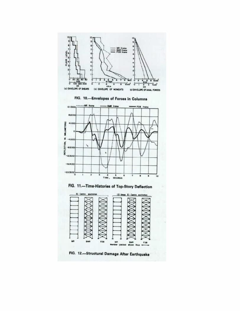
resisting (MR) frame and braced moment resisting (BMR) frame. The results, unless otherwise indicated are presented for El Centro excitation. 1. Deflection envelopes of the three frames are shown in Fig. 8. It is seen that due to hysteretic damping, the deflection at the top of the FDB frames is about 40% of MR frame and about 50% of the so-called stiff BMR frame. The story drift of the MR frame has exceeded the maximum limits provided in the codes (15). In the case of FDB frame, it was far less than the maximum permissible limits even at 1.5 times El Centro excitation. 2. Maximum moments in the beams are shown in Fig. 9. It is seen that all the beams, except the top story, have yielded in the MR frame, and six beams have yielded for the BMR frame, but no beam yielded in the FDB frame. 3. Maximum shear envelope of the columns is shown in Fig. 10(a). The maximum shear at the base of the FDB frame is only 70% and 80% of the BMR and MR frames, respectively. The moment envelope of the columns is shown in Fig. 10(b). The maximum moment at the base of FDB frame is 75% and 68% of the MR and BMR frames, respectively. The maximum tensile or compressive force envelope in the columns is shown in Fig. 10(c). The axial forces in the FDB frame are, of course, higher than the MR frame because of the additional coupling provided by the braces but are only 75% of the BMR frame. 4. Time-histories of the deflection at the top of building for all the three frames are shown in Fig. 11. The peak amplitude of the FDB frame is far less than the other two frames. The vibrations at the tenth second, i.e. three seconds after the termination of the forcing motion, are almost negligible in the FDB frame compared with the other two frames. Since all the members of the FDB frame remain in the elastic stage, the building recovers with almost no permanent set. If the building is slightly out of aligmnent, it can be simply corrected by loosening the bolts in the device and then retightening.
5. The damage experienced by different frames after being subjected to earthquake excitation is shown in Fig. 12. It is seen that at the level of El Centro,90% of the beams and 10% of the columns yielded in the MR frame, 60% beams and 90% braces yielded in the BMR frame, while none of the members yielded in the FDB frame. Of course, all the braces of the FDB frame slipped and participated in the process of energy dissipation, but slipping of the brace in friction does not constitute damage. At 1.5 times El Centro excitation, the percentage damage of the MR frame elements remained unchanged, but the deformations increased much more; the damage in the BMR frame rose to 80% for beams and 100% for braces. In the case of the FDB frame, only 40% of the beams yielded slightly with no damage to other elements.
CONCLUSIONS
The results of these studies have shown that the use of inexpensive friction damper in the bracings of the steel framed buildings can significantly enhance their earthquake resistance. In brief, the concept is of particular importance for the following reasons: 1. Energy is dissipated mechanically throughout the height of the building rather than by localized inelastic action of the main structural members. 2. The frame is softened without losing its elasticity and recovers with little or no permanent set. 3. The friction device acts like a structural damper to control the amplitude and as a safety valve to limit the loads exerted. 4. The amplitude of vibrations and accelerations are considerably reduced; thus secondary damage is minimized. 5. The resonance of the structure is difficult to establish, i.e. the device acts like an automatic gear in limiting the input energy. 6. The building can be "tuned" for optimum response without resorting to expensive devices. 7. There is no yielding of materials involved in the process of energy dissipation, thus no damage is caused and the structure is ready to face future earthquakes with the same efficiency. In this manner, the concept raises the level of earthquake resistance philosophy from the avoidance of collapse to the control of secondary damage. The device also can be conveniently incorporated in existing framed buildings to upgrade their seismic resistance.
APPENDIX 1.-RFFERENCES
1. Degenkolb, H. J., "Practical Design (aseismic) of Steel
Structures," Canadian Journal of Civil Engineers,,Vol. 6, 1979, pp. 292-307@,.
2. Goel, S. C., and Hanson, R. D., "Seismic Behaviour of Multistory Braced Steel Frames," Journal of the Structural Division, ASCE, Vol. 1 00, No. ST 1, Proc. Paper 10288, Jan., 1974, pp. 79-97.
3. Kannan, A. E and Powell, G. H., "Drain-2D, A General Purpose Computer Program for Dynamic Analysis of Inelastic Plane Structures," College of Engineering, University of California, Berkeley, Calif. 1973.
4. National Building Code of Canada, 1977, Commentaries. on Part 4, Supplement No. 4, National Research Council of Canada, Ottawa.
5. Pall, A. S., Marsh, C., and Fazio, P., "Limited Slip Bolted Joints for Large Panel Concrete Structures," Proceedings,
International Symposium-Behavior of Building Systems and Building Components, Vanderbilt University, Nashville, Tenn., Mar., 1979, pp. 38@.
6. Pall, A. S., and Marsh, C., "Seismic Response of Large Panel Structures Using Limited Slip Bolted Joints," Proceedings, Third Canadian Conference on Earthquake Engineering, Montr6al, Canada, June, 1979, pp. 899-916.
7. Pall, A. S., "Limited Slip Bolted Joints-A Device to Control the Seismic Response of Large Panel Structures," Thesis presented to the Centre for Building Studies, Concordia University, at Montr6al, Canada, in 1979, in partial fulfilment of the requirements for the degree of Doctor of Philosophy.
8. Pall, A. S., Marsh, C., and Fazio, P., "Friction Joints for Seismic Control of Large Panel Structures," Journal of the Prestressed Concrete Institute, Nov./Dec., 1980, Vol. 25, No. 6, pp. 38-61.
9. Pall, A. S., and Marsh, C., "Optimum Seismic Response of Large Panel Structures Using Limited Slip Bolted Joints," Proceedings, Seventh World Conference on Earthquake Engineering, Istanbul, Turkey, Sept., 1980, Vol. 4, pp. 177-184.
10. Pall, A. S., and Marsh, C., "Friction Damped Concrete Shear Walls," Journal of American Concrete Institute, May~June, 1981.
11. Popov, E. P., and Bertero, V. V., "Seisn-iic Analysis of Some Steel Building Frames," Journal of the Engineering Mechanics Division, ASCE, No. EM1, Proc. Paper 15194, Feb., 1980, pp. 75-92.
12. Popov, E. P., Takanashi, K., and Roeder, C. W., "Structural Steel Bracing Systems: Behavior Under Cyclic Loading," EERC Report 76-17, Earthquake Engineering Research Center, University of California, Berkeley, Calif., June, 1976.
13. Roeder, C. W., and Popov, E. P., "Inelastic Behavior of Eccentrically Braced Steel Frames Under Cyclic Loadings, " EERC Report No. 77~1 8, Earthquake Engineering Research Centre, University of Califwpmia, Berkeley, Calif., Aug., 1977.
14. Roeder, C. W., and Popov, E. P., "Eccentrically Braced Steel Frames for Earthquakes," Journal of the Structural Division, ASCE, Vol. 104, No. ST3, Mar., 1978, pp. 391-41 1.
15. "Tentative Provisions for the Development of Seismic Regulations for Buildings," Special Publication 510, Applied Technology Council, U. S. National Bureau of Standards, Washinton, D.C., June, 1978.
16. Uniform Building Code, International Conference of Building Officials, Whittier, Calif., 1976 ed.
17. Wakabayashi, M., Matsui, C., Minami, K., and Mitani, I., "Inelastic Behavior of Full Scale Steel Frames with and Without Bracing," Bulletin Disaster Prevention Research Institute, Kyoto University, Kyoto, Japan, Vol. 24, Part 1, No. 216, Mar., 1974.
18. Workman, 0. H., "The Inelastic Behavior of Multistory Braced Frame Structures Subjected to Earthquake Excitation," Research Report, University of Michigan, Ann Arbor, Mich., Sept., 1969.