Embed Size (px)
Citation preview
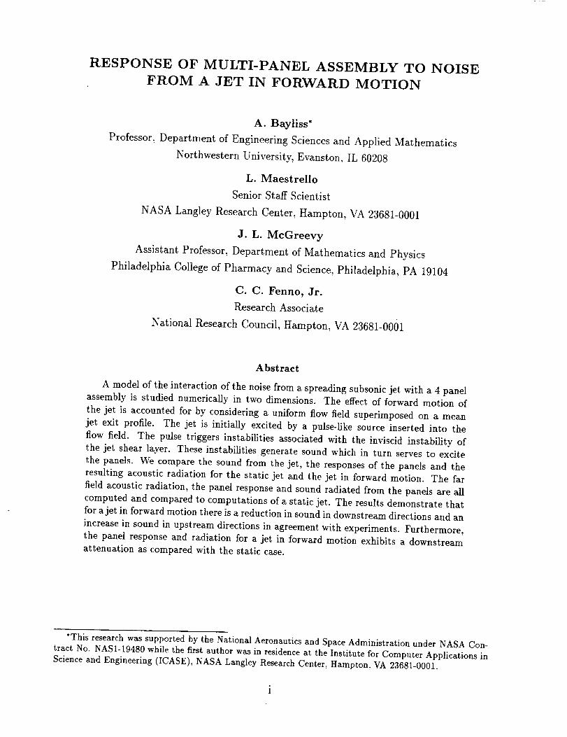
NASA Contractor Report 198164
ICASE Report No. 95-41
r/{/
3
?_
SRESPONSE OF MULTI-PANEL ASSEMBLY TO
NOISE FROM A JET IN FORWARD MOTION
A. BaylissL. Maestrello
J. L. McGreevy
C. C. Fenno, Jr.
(_ASA-C_-198154) RFSPONSE OF
MULTI-PANEL ASSEMBLY TO NOISfi
A JET IN fORWARD MOTION Final
Report (ICASE) 30 p
FROM
Unclas
G3/34 0051395
Contract No. NAS 1- 19480
May 1995
Institute for Computer Applications in Science and Engineering
NASA Langley Research Center
Hampton, VA 23681-0001 /f_
Operated by Universities Space Research Associ

RESPONSE OF MULTI-PANEL ASSEMBLY TO NOISE
FROM A JET IN FORWARD MOTION
A. Bayliss*
Professor, Department of Engineering Sciences and Applied Mathematics
Northwestern University, Evanston, IL 60208
L. Maestrello
Senior Staff Scientist
NASA Langley Research Center, Hampton, VA 23681-0001
J. L. MeGreevy
Assistant Professor, Department of Mathematics and Physics
Philadelphia College of Pharmacy and Science, Philadelphia, PA 19104
C. C. Fenno, Jr.
Research Associate
National Research Council, Hampton, VA 23681-0001
Abstract
A model of the interaction of the noise from a spreading subsonic jet with a 4 panel
assembly is studied numerically in two dimensions. The effect of forward motion of
the jet is accounted for by considering a uniform flow field superimposed on a mean
jet exit profile. The jet is initially excited by a pulse-like source inserted into the
flow field. The pulse triggers instabilities associated with the inviscid instability of
the jet shear layer. These instabilities generate sound which in turn serves to excite
the panels. We compare the sound from the jet, the responses of the panels and the
resulting acoustic radiation for the static jet and the jet in forward motion. The far
field acoustic radiation, the panel response and sound radiated from the panels are all
computed and compared to computations of a static jet. The results demonstrate that
for a jet in forward motion there is a reduction in sound in downstream directions and an
increase in sound in upstream directions in agreement with experiments. Furthermore,
the panel response and radiation for a jet in forward motion exhibits a downstream
attenuation as compared with the static case.
*This research was supported by the National Aeronautics and Space Administration under NASA Con-tract No. NAS1-19480 while the first author was in residence at the Institute for Computer Applications inScience and Engineering (ICASE), NASA Langley Research Center, Hampton, VA 23681-0001.

1. Introduction
This paper describes the results of a numerical simulation of jet noise in the presence of
four flexible aircraft-type panels in a panel-stringer assembly. The simulation is based on
a model which fully couples the fluid dynamics of the jet flow to the panel motion and the
resulting acoustic radiation while accounting for the forward motion of the jet. The primary
objective is to determine the role played by forward motion on installation effects from the
nearby flexible structure and on the response and the acoustic radiation from the structure.
In previous work[18] we have computed the far field sound, panel response and radiation
from a static jet with a two panel model. Computations with a static jet model the response
of a jet on the ground. However, the acoustical behavior of a static jet is not sufficient to
determine the behavior for a jet in flight. The noise radiated from the jet in the downstream
direction should decrease with an increase in the forward velocity from its static level due
to the reduced shear resulting from the lower relative velocity between the jet and its sur-
roundings. The effect of forward motion on panel response and radiation has not yet been
completely determined. We describe here the effect of forward motion on the response and
radiation of the panels. We note that the results presented here do not include the effect of
the boundary layer on panel excitation in the forward motion case. It is possible that for
some parameter range, the boundary layer can result in enhanced loading on the panel with
increasing forward velocity.
The problem of simulating the behavior of a jet in flight has previously been studied
analytically and experimentally. Analytic methods generally begin with a formulation of the
exact sources,[15, 25] and models of the sources to account for flow effects.J10, 15] Models
of the Lighthill sources have been applied within a convective wave equation formulation
to develop scaling relations between static measurements and measurements in flight.[22]
These analyses demonstrated reduction in noise emmision downstream of the jet together
with amplification in the forward direction under certain circumstances.
There have also been extensive experimental studies of forward motion effects. Measure-
ments on a moving structure, the Bertin A@rotrain, have been reported.J9] These results,
obtained for locations fixed on the ground, showed a general reduction in level along the jet
axis, but under certain conditions there was sound amplification in forward directions. Mea-
surements of a jet in flight[5] and wind tunnel measurements, in which the forward motion
effect is simulated by co-flowing air streams and measurements are taken at points fixed with
respect to the jet, have also been obtained for both subsonic and supersonic jets.[6, 24, 26]
A comparison of sound produced by a moving jet with wind tunnel measurements was per-
formed (i.e., receivers fixed with respect to the ground and receivers fixed with respect to
the jet) and indicated that both methodsgavequalitatively similar results.[23]
An important featureofour modelis the direct computationof at leastsomeof thenaturalsourcesof jet noise,namelyfluid dynamicalinstability waveswhich de_'elopdue to instability
of the jet shearlayer. Experimentshavedemonstratedtheexistenceof largescalestructures
or instability wavesin jets.[7, 14,19]Thesestructuresarebelievedto act assourcesof sound,
a point also confirmedby analytical studies[4,13,21, 20] and computations.[1, 17, 19]
Various approacheshavebeenemployedto determinethe panelresponseto jet noiseor toother sourceswhich cannot be easilycalculated. In one important approachthe sourcesin
the flow field canbe taken from experimentalmeasurements,(e.g., [8]). The panel response
couldthen itself becomputedvia solutionof the resultingpanelequation from the measured
sourcesas in [8]. In the approachadoptedhere, the panel sourcesare computedfrom the
fluid dynamics and acousticsof the jet and employedin a fully coupledmanner to compute
panel response.
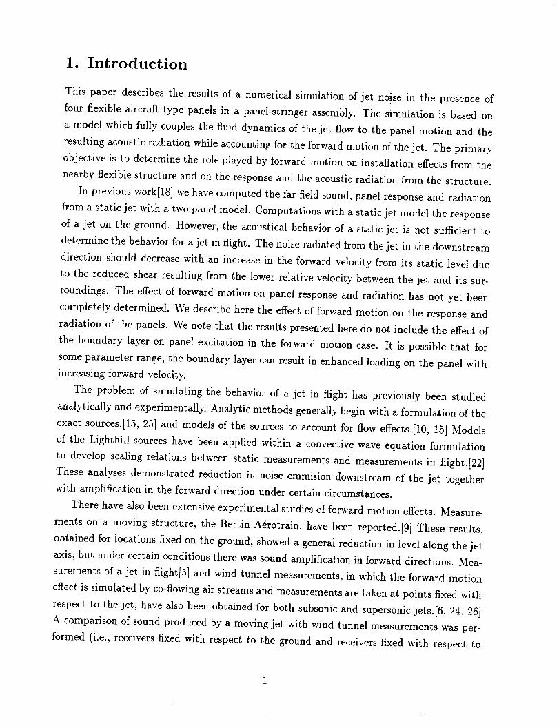
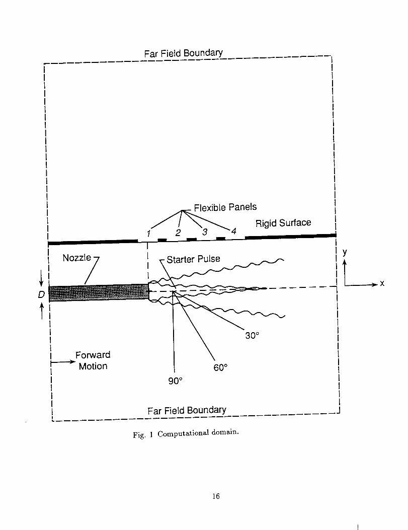
The geometry of our computational model can be seenin Figure 1. We solvethe Euler
equationsin two domains,the jet domainand the radiation domain simulating the aircraft
cabin. Panel responseand radiation are also computed and are fully coupled to the fluid
dynamics in the sensethat the fluid dynamicscomputation providesthe pressuredifference
acrossthe panelswhile the computation of the panel displacementprovides a boundarycondition for the fluid computation. Thejet is initially excitedby a starter pulse,represented
as a finite duration sourcein the Euler equations.The initial pulsepropagatesthrough the
jet flow field, thus allowinga study of propagationeffectswith forward motion. The pulsealso excites instability wavesin the jet. Thesewavesare sourcesof sound radiating into
the far field, leading to sustainedacousticactivity in the jet. Thus, sinceour model allows
computation of these important natural sourcesof jet noise,the forward motion effect onthesesourcesis computedrather than modeled. In addition, the excitation of the panel
(i.e., the pressuredifferenceacrossthe panels)is computeddirectly from the Euler equations
and fully coupledto the motion of the panelssothat no modelingof the panelexcitation is
employed.
The paper is organizedas follows. In section 2 there is a description of the model anda discussionof the numericalmethod and boundary conditions. In section 3 wepresentour
results. In section4 we summarizeour resultsand provideconclusions.
2. Problem Formulation
The computational domain is shown in Figure 1. Unsteady pressure, density and velocities
are computed in two domains, that which contains the jet, exiting from a nozzle of width D,
and the domain on the other side of the wall boundary. We will refer to the two domains as
the jet and radiation domains respectively. The wall boundary is a rigid wall containing 4
adjacent flexible panels (denoted as panels 1-4 in Figure 1) with rigidly clamped boundaries.
The panels vibrate in response to excitation from jet noise and radiate sound into both
domains. We focus primarily on acoustic radiation into the radiation domain, as the radiation
into the jet domain is small compared to the large disturbances already present in the jet.
The numerical method involves coupling the computation of a nonlinear equation gov-
erning the panel responses (the beam equation) to an Euler computation performed in both
the jet and radiation domains. The panel vibration is fully coupled to the fluid dynamics
in that at each timestep the pressure difference across the panels, computed from the Euler
computations, serves as a forcing term for the beam equation. Similarly, the displacement
obtained from the beam equation is differentiated in time and is imposed as a boundary con-
dition for the Euler computations. The numerical method has been described in detail.[18]
The presentation here will be brief.
The nonlinear beam equation is
D 4z - N ' = p+02z 02z Oz
b-g-2s x-g- z + pbn-giT+ -y-gi - p-, (1)
where z represents the beam transverse deflection, pb the mass per unit volume of the beam,
h the beam thickness, _/ the physical damping, and Db = Mh3/12(1 - ,2) is the stiffness
of the beam where M is the modulus of elasticity and v is the Poisson ratio of the beam
material. The coefficient N_ of the nonlinear term represents the tension created by the
stretching of the plate due to bending. The pressures in the radiation and jet domains are
p+ and p- respectively. The solution of (1) is obtained at each timestep using an implicit
finite difference method. The panels are assumed clamped at both ends.
The coupling of the beam computation to the Euler computation occurs through the
forcing term given on the right hand side of equation 1. The pressures p+ and p- are
obtained from the Euler computation using an explicit scheme. The displacement at the
new time level is then obtained from solving (1) one time step. The normal velocity, v, is
then obtained from differentiating z and employed as a boundary condition to complete the
update to the Euler computation. Since this procedure is employed at each timestep, the
fluid and structural calculations are fully coupled.
The Euler equations are solved in conservation form for the vector
_,, = (p, pu, pv, E) T,
where p is the density, u, v are the x and y components of the velocity respectively and E is
3
the total energy per unit volume,
1 2E = p(u + v +
where T is the temperature and c. is the specific heat per unit volume. The pressure, p, is
obtained from the equation of state. The Euler equations are solved separately in both the
jet and radiation domains.
In the jet domain the Euler equations are modified to account for the jet flow. We assume
a straight pipe of width D from which the jet exits. The solution is computed both within
and exterior to the pipe. The Euler equations are modified to account for two different source
terms.J18] One source serves as a starter pulse to excite the jet. It corresponds to a localized
source of mass injection at the location (xs, yj), where yj is the location of the jet axis
(approximately 6D from the wall) and x8 is approximately 1.2D. The second source term
is designed so that in the absence of the starter pulse the solution to the Euler equations
would be a stationary profile corresponding to a spreading jet. The inclusion of this source
term separates the computation of the disturbance, in particular the resulting instability
waves, from the computation of the mean flow (i.e., the spreading jet). Thus, the resulting
system of equations allows for the simulation of instability waves and the resulting sound
generation, together with the bending of acoustic waves in the jet flow field without requiring
the computation of the spreading jet itself. Although this is a simplified model, the resulting
system captures many of the observed features of instability wave generated jet noise and
permits high resolution computation of the coupling of jet noise with the flexible panels and
the resulting radiation from the panels. In particular, the model allows for computation of
the natural sources of jet noise (the instability waves) together with the sound radiated by
these sources.
The initial conditions are taken to be the mean state @0 in the jet domain and ambient
data in the radiation domain. The boundary conditions are as follows (refer to Figure 1):
1. Bounding wall - rigid conditions are imposed except for the flexible panels which are
treated as described above.
.
.
Pipe - rigid on interior, impedance on exterior. The use of impedance boundary condi-
tions on the exterior of the pipe simulates the use of an absorbing material to absorb
waves incident on the pipe from the exterior.
Inflow for the pipe - characteristic conditions. Specifically we linearize the Euler equa-
tions about the ambient state, assumed to hold far upstream in the pipe, and impose
the three incoming characteristics,
p + pcu, v, c_,p - p/c_
to be the values that they would have far upstream. It has been shown[19] that this
boundary condition is valid for the lowest propagating mode in the pipe. The boundary
condition can lead to reflections on higher modes, however any such reflections do not
effect the data outside the pipe for the time intervals considered here.
4. All other boundaries in the problem are artificial. Non-reflecting (radiation) boundary
conditions are imposed to prevent spurious reflections from propagating into the inte-
rior. These boundary conditions are based on a far field expansion of the solution.[2, 3]
When there is forward motion, two additional boundary conditions should be imposed
at inflow. We impose the conditions
c_p - p/c_ = c_p_ - p_/c_,
simulating isentropy at inflow, and
My _ Ux _ O,
simulating irrotational flow at inflow. For the values of the forward motion motion considered
here these boundary conditions have a negligible effect on the solution.
We employ a finite difference scheme which is fourth order accurate in space and second
order in time. The scheme is a generalization of the second order MacCormack scheme
to allow higher order accuracy in space.[ll] The scheme is discussed in detail in other
publications. [17, 19]
3. Results
We consider a configuration as indicated in Figure 1. The jet exits from a straight nozzle
of width D = 2in. The infinite wall is located approximately 6D above the jet and parallel
to the nozzle. The wall is assumed rigid, except for four regions where flexible, aluminum,
aircraft-type panels with clamped boundaries are located. The panels are of length 5D,
thickness 0.01D and are centered at x = 0D, x = 5.22D, x = 10.44D, and x = 15.66D
respectively. We refer to these panels as Panels 1, 2, 3 and 4. Other parameters of the
panels are typical of aluminum. The parameters of the starter pulse have been reported
previously.[18] The peak frequency is close to 1000 Hz.
The origin of coordinates is chosen to be the horizontal location of the nozzle exit for x
and the vertical location of the rigid wall for y. Both the jet and radiation domains extend
48D downstream from x = 0, 36D in the upstream direction and 48D in the y direction. We
employ a grid of 811 x 501 points in the jet domain and 441 x 301 points in the radiation
domain. The grid in the jet domain is stretched to improve resolution of the jet shear layer
5
and sourceregion. The grid in the radiation domain is uniform. The computations have
beenvalidated by grid refinement.J18]
We consider two computations. In the first computation we assume a static jet with exit
velocity Uj = 0.65 c_. We refer to this computation as the static computation. In the second
computation we model a forward motion effect with a uniform flow of speed U s = 0.20 co_
in the x-direction superimposed on the jet mean flow. The Mach number for the mean
jet profile is 0.45 so that the exit velocity from the nozzle is still 0.65co_, but the jump in
velocity across the jet boundary is now 0.45 c_. We refer to this computation as the forward
motion computation. This models a wind tunnel experiment of forward motion effects. We
note that in the forward motion computation, we compute the sound at points which are
fixed with respect to the jet, simulating measurements at a fixed location in a wind tunnel.
Our results are presented in three parts; the jet domain, including the flow and acoustic
radiation from the jet, the responses of the panels and the acoustic radiation from the panels.
3a. Jet Flow Domain
Nonstationary behavior in the jet is triggered by the pulse starter, which generates a distur-
bance that propagates through the jet, interacts with the shear layer and then propagates
into the farfield as sound. This disturbance is non-circular due to the flow. Additional dis-
turbances due to purely geometric affects, such as reflection from the wall and scattering
from the nozzle lip, are also generated. In addition, instability waves are generated due to
the interaction of the acoustic disturbance with the shear layer gradient of the jet profile.
These instability waves propagate slowly downstream along the jet axis and are sources of
sound;[17] indeed they are important natural sources of sound in subsonic jets. After an
initial growth, their amplitude decays due to the spreading of the mean velocity.
As the instability waves propagate downstream they act as sources of disturbances which
propagate into the far field as sound.[15, 16, 20, 21, 25] These disturbances also trigger
additional disturbances from the nozzle lip, leading to a sustained response of the jet. This
behavior is also consistent with experimental observations[4, 7] and with previous linear
and nonlinear computations.J19, 1] The resulting sound radiation forces the panels into a
broadband, sustained response which in turn leads to a sustained radiation of sound from
the panels. The acoustic radiation persists after the initial disturbance generated by the
pulse starter has propagated a significant distance from the panels and away from the region
of interest.
In this section we examine both the total pressure history at given far field locations (i.e.,
including both the starter pulse and the jet noise generated by the instability waves) and
only the jet noise. In the later case we consider a specified interval in nondimensional time
t (10 < t < 15) after the starter pulse has passed through the selected points. Changing the
selected interval leads to quantitative changes but does not change the qualitative pattern
of the far field sound. Examination of the starter pulse permits a_ study of the effect of
forward motion on wave propagation through the jet flow while examination of the long
time behavior permits a study of sound generation from the instability waves.
It has been both observed and predicted that forward motion leads to a reduction in
sound downstream of the jet and an increase in sound in the upstream direction (i.e., a
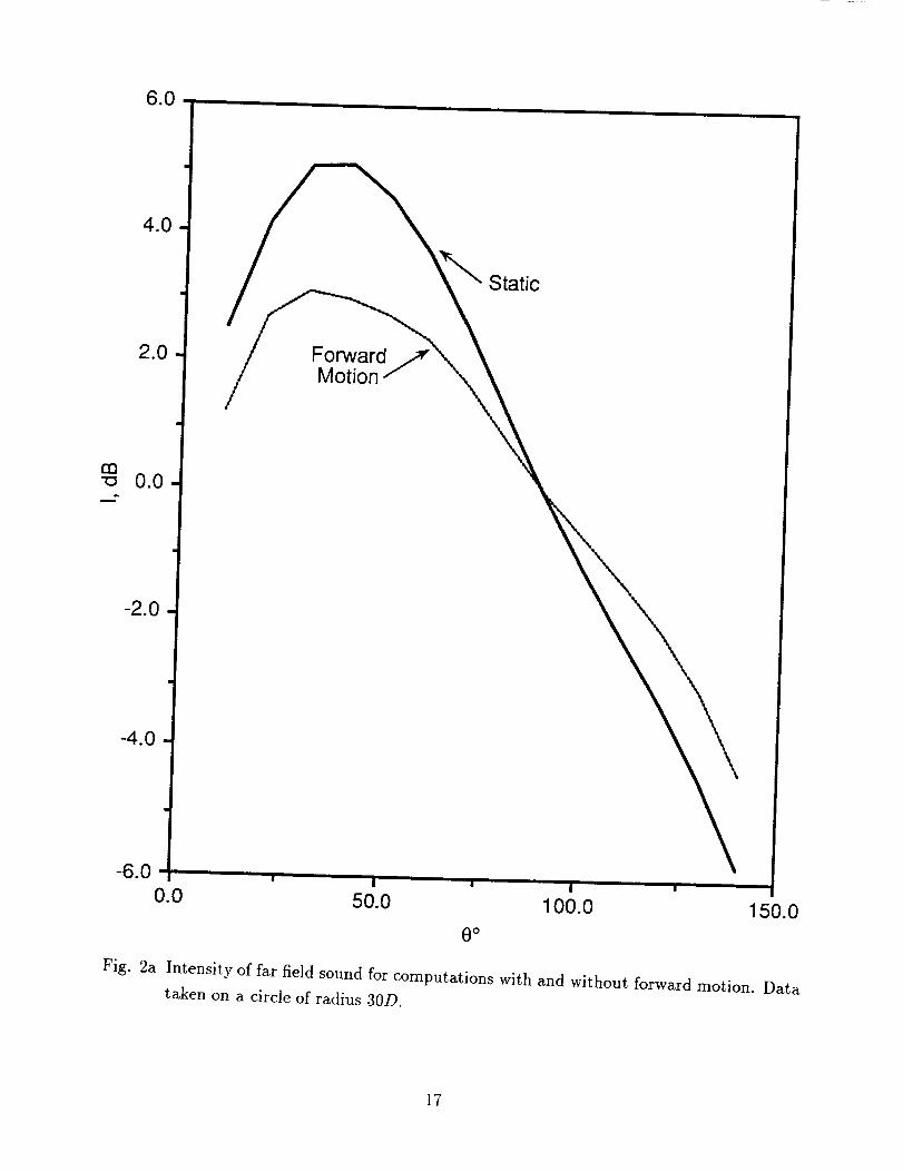
forward arc amplification[9, 22]). We illustrate this in Figure 2a where we plot the logarithm
of the time integrated intensity I, i.e.,
(f0r I = 10 logle 2dt/T)
around a circle of radius 30D from the source. The decibel level is normalized to 0 for the
static computation at 90 ° . The results clearly demonstrate the downstream attenuation of
sound and upstream amplification in qualitative agreement with experiments and analysis.
We note that the forward arc amplification is noticeable only for angles greater than 90 °.
The level of sound with forward motion is nearly the same as for the static computation at
900 .
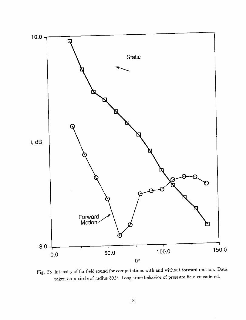
In Figure 2b we plot the analogous figure for
f] = 10log,0( - tl)),
where tl = 10 and t2 = 1.5 thus examining the effect of forward motion on sound generated
from the jet. The data is again normalized so that 0 db is a.t 90 ° for the static computation.
We note that the qualitative effect of forward motion is similar; there is a reduction along
the let axis and a forward arc amplification. We note that there are now significantly larger
differences between the computations with and without forward motion, thus indicating a
greater effect of forward motion on sound generation from the instability waves than from
wave propagation.
In summary these figures indicate that the observed properties of forward motion, namely
a reduction in observed sound downstream and an amplification upstream can be explained as
both a wave propagation effect, as evidenced by the behavior shown in Figure 2a accounting
for the total pressure field, and as a sound generation effect, as shown in the long time
behavior in Figure 2b.
Examination of the pressure histories for i_ = p - p_ at various angles, confirm the
results in Figures 2a and 2b. In particular, there is an amplification at mid angles both
with and without forward motion. There is very little effect of forward motion at 90 ° .
The primary effect of forward motion is to attenuate low frequencies for low to mid-range
angles downstream. Examination of the spectrum of ifi indicates that the installation effect,
i.e., forward motion, reflections from the wall and coupling between the wall and the jet,
significantly alters the spectrum of the far field sound, particularly_- for low to mid-range
angles.
3b. Panel Response
We categorize the panel response by considering (i) the pressure incident on the panels, (ii)
velocities of the panels and (iii) transmitted pressure.
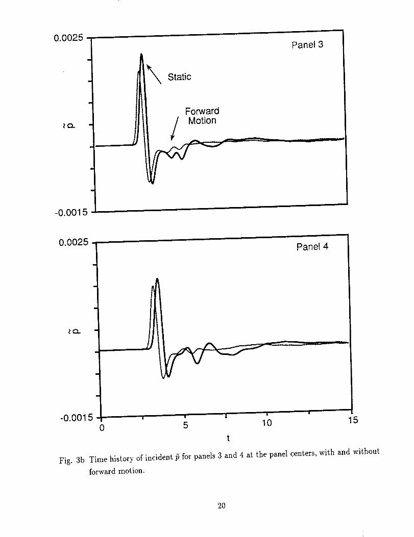
In Figures 3a and 3b we consider the pressure at the panel centers on the jet side for
panels 1 and 2 (Figure 3a) and panels 3 and 4 (Figure 3b), respectively. Although this data
includes the effect of reflections from the panel, these reflections are small compared to the
pressure incident from the jet and we refer to this quantity as the incident pressure. All
figures are plotted on the same scale. The effect of convection can be seen in that for panel
1 (upstream of the source) the primary arrival is slightly delayed with forward motion, while
for the other panels the primary arrival is advanced with forward motion. The time difference
between the leading arrivals with and without forward motion increases with distance of the
panel from the source location. There is a slight increase in level for panel 1 (consistent with
the forward arc amplification observed in Figure 2a for the far field pressure). There is an
overall reduction in level for the primary arrivals for the downstream panel, again consistent
with the downstream attenuation due to forward motion.
Only very weak additional arrivals are observed for panel 1. In previous calculations
we have found that panel 1 is only weakly influenced by sound from the instability waves.
Rather, the primary feature of panel 1 is the geometric effect of repeated reflections be-
tween the nozzle and the panel. This was pronounced in analogous results without forward
motion[18] where the exterior surface of the nozzle was assumed rigid. In the present com-
putations we have employed impedance conditions on the exterior surface of the nozzle in
order to deemphasize these reflections which are not of direct interest in this paper.
The effect of additional arrivals, due to additional sound generated from instability waves
can first be seen for panel 2, and becomes more pronounced for panels 3 and 4. The time
duration of these additional arrivals increases with the downstream distance of the panels,
suggesting panel excitation at lower frequencies which is confirmed by the spectral plots be-
low. It is clear from the figures that the amplitude of these additional arrivals is reduced due
to forward motion. Furthermore the amount of the reduction increases with the downstream
distance of the panels.
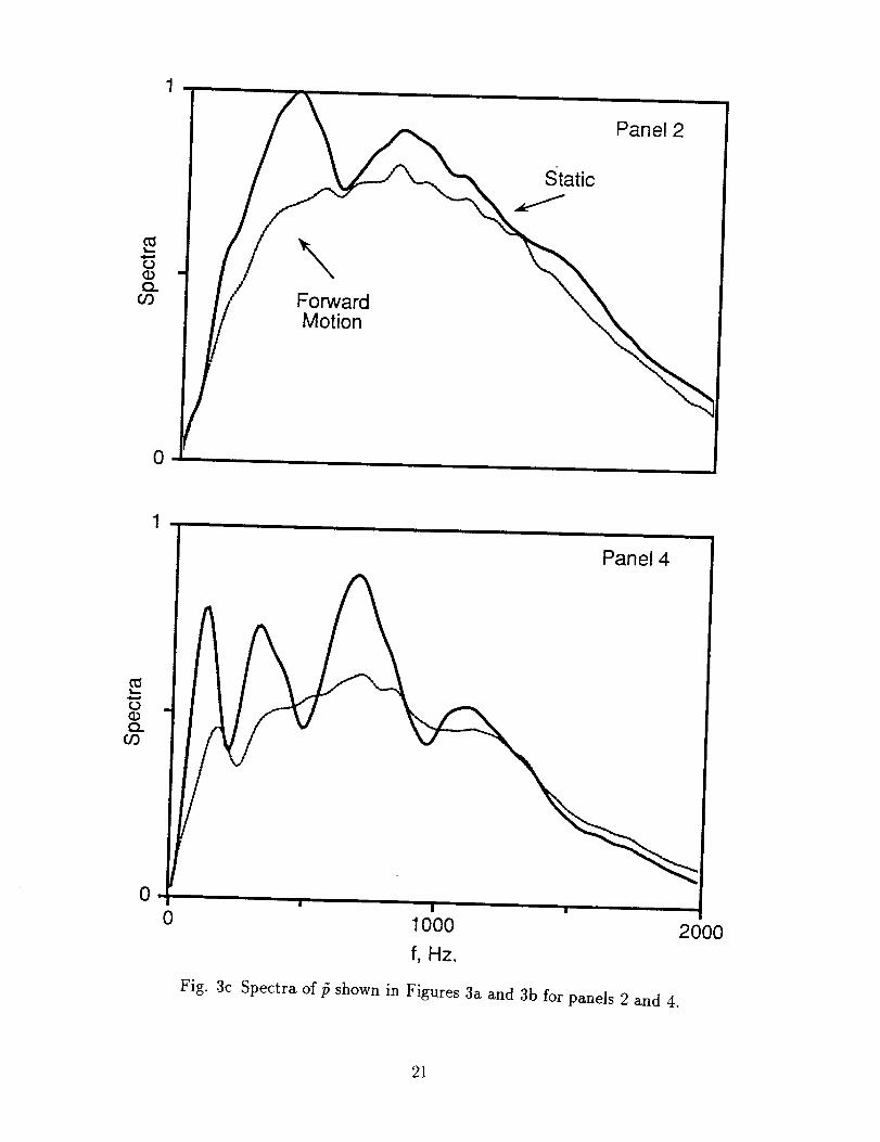
The spectra of the incident pressure is shown in Figure 3c for panels 2 and 4. The
data in this figure is normalized by the maximum over both panels. It can be seen that the
pressure incident on panel 2 is more broadband than for panel 4 where the spectrum exhibits
a more rapid roll off with increasing frequency. Thus the spectrum is more concentrated at
lower frequencies as the downstream distance of the panel increases, consistent with the time
histories in Figures 3a and 3b. The lowest frequencies are significantly enhanced for panel
4. We believe that the relatively large secondary arrivals in the static case, due to sound
generated from instability waves, leads to an interference effect which causes the oscillatory
character of the spectrum in this case. These arrivals are weaker with forward motion, thus
resulting in a smoother spectrum. In both cases the attenuation due to forward motion
can be seen to be concentrated in the low to middle frequency band. There is virtually no
attenuation due to forward motion for frequencies greater than 1500 Hz.
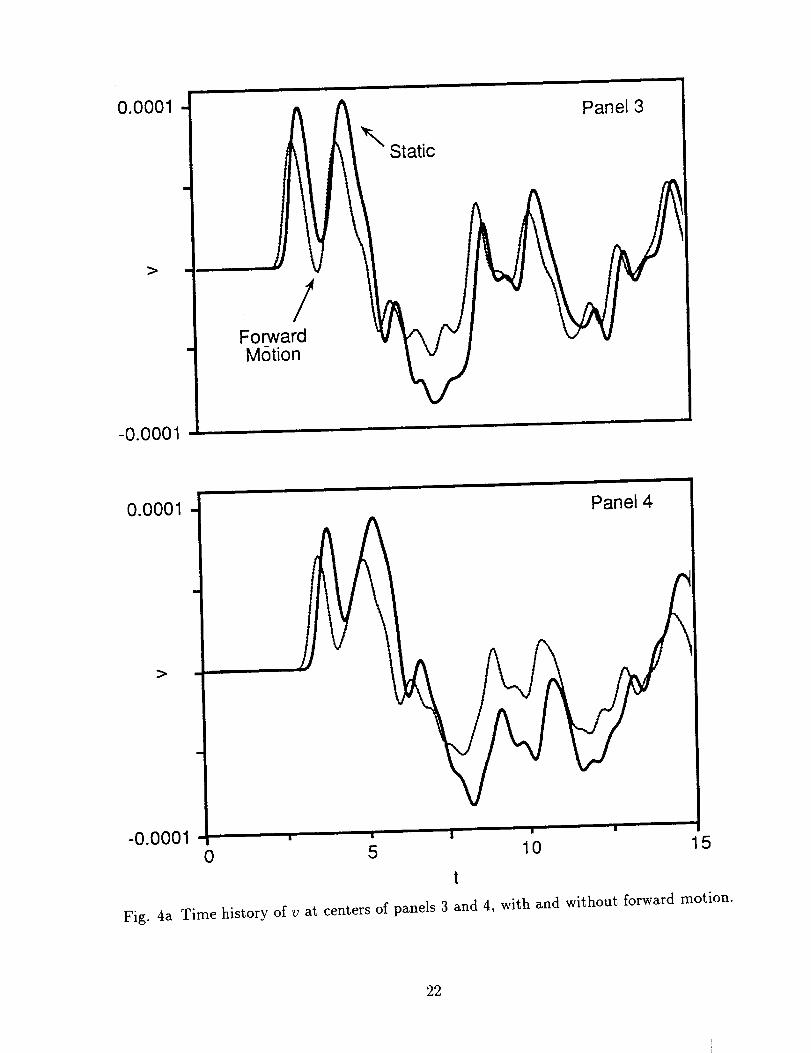
In Figure 4a we show time histories of the normal velocities (v) at the panel centers
for panels 3 and 4. There is a sustained long time oscillation for v, even after the primary
wave of incident pressure has passed by the panel. This is probably due to the low level
of damping of the panels and panel excitation by disturbances shed from the instability
waves. There appears to be little qualitative difference between the time histories for v as
the downstream distance of the panel increases. Furthermore, the time histories with and
without forward motion are similar. This suggests that much of the differences observed in
the incident pressure due to panel location and to forward motion are not transmitted to
the panel motion.
This is supported by analysis of the spectrum of v (not shown), which is relatively
discrete. This is consistent with previous results[18] and indicates that the panels act as
filters to convert the relatively broadband incident pressure into relatively discrete spectral
bands for the panel response. In addition, the peak frequencies appear to be relatively
insensitive to panel location and to whether forward motion is present or not. The frequency
response is very similar for all panels and for the computations with and without forward
motion.
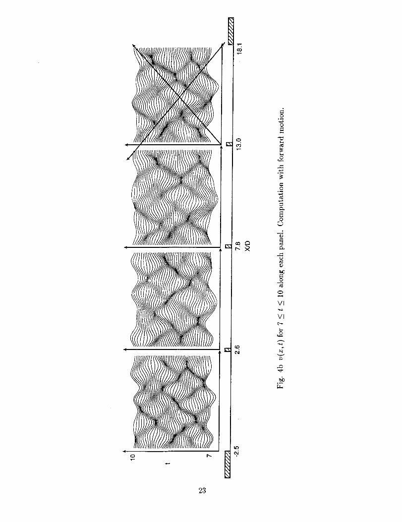
In Figure 4b we plot v along each panel for different values of non-dimensional time, t.
The figures are for the time window 7 _< t _< 10. The predominant effect is that of waves
propagating in both directions along each panel and reflecting from the clamped edges. The
dark spots on the figures correspond to space/time locations where right moving and left
moving waves intersect. Generally these intersections occur with a phase lag from panel to
panel indicating the convection of disturbances along the panel array. This is particularly
noticeable in comparing panels 2, 3 and 4. Due to the restriction to a specific time window,
this figure is most useful for assessing panel response in the mid and high frequency range.
Low frequency responses would not be brought out in these figures. Also note that each
figure is internally scaled so that amplitude effects from panel to panel would not be visible in
thesefigures. Correspondingfiguresfor the static computation (not shown)arequalitatively
similar, confirming the conclusionsdrawn from the moredetailed Figure 4a that differencesin incident pressuredue to forward motion aremanifestedprimarily m the amplitude of the
panel response in the low frequency range.
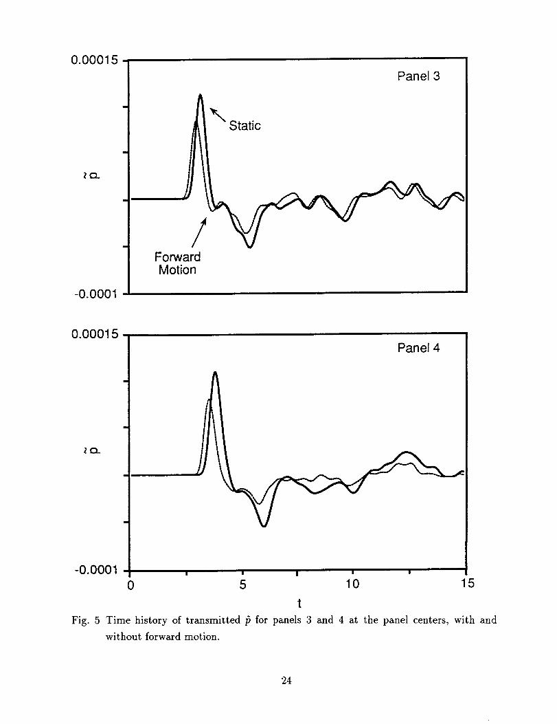
In Figure 5 we consider the pressure in the radiation domain directly behind the panels
(transmitted pressure) and at the panel centers for panels 3 and 4. The transmitted pressure
exhibits features of both the incident pressure and the panel velocity. There is an initial
disturbance corresponding to the incident pressure wave and a long time sustained response.
This response is largely due to the low damping of the panels although the excitation of the
downstream panels, -particularly panel 4, is also influenced by relatively large later arrivals
generated from the instability waves.
Examination of the other panels indicates that the amplitude of the primary disturbance
is slightly delayed and enhanced for panel 1, consistent with the behavior of the incident
pressure in the jet domain. For the other panels the incident wave arrives earlier and is
attenuated with forward motion. Thus, these effects of forward motion are transmitted into
the radiation domain. There is a noticeable attenuation in the amplitude of the long time
pressure disturbances for panel 4 with forward motion. This may be due to the enhanced
low frequency forcing of panel 4.
Examination of the spectral content of the transmitted pressure (not shown) indicates
a behavior similar to that observed for v. The spectrum is again composed of relatively
discrete frequency bands in contrast to the incident pressure, illustrating the role of the
panels as a filter to convert the relatively broadband incident pressure into discrete frequency
bands. In the low frequency range, the characteristic frequencies of the bands appear to be
relatively insensitive to the panel location or to whether there if forward motion or not. The
predominant effect of the transmitted pressure is the large low frequency responses for panel
4, and the relatively large attenuation of this response with forward motion.
In summary these figures indicate that (i) the panels act as filters converting broadband
incident pressure into relatively narrow spectral bands, (ii) panels located farther downstream
are excited at lower frequencies and (iii) an important effect of forward motion is to attenuate
the low frequency forcing for panels farther downstream, resulting in a significant attenuation
in panel response and radiation.
3c. Acoustic Radiation from the Panels
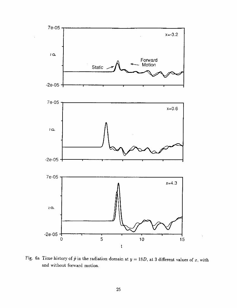
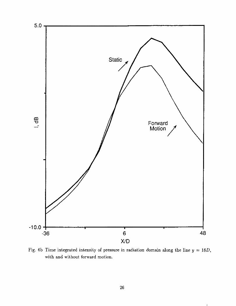
We have computed the radiated pressure for various x locations on a line y = 18D (corre-
sponding to 3 ft.) in the radiation domain. Results for 3 different x locations are shown in
Figure 6a. The x locations are indicated in feet on the graph. The results show a leading ar-
10
rival, followed by sustained pressure disturbances, similar to the transmitted pressure shown
in Figure 5a. There is a strong attenuation in the pressure for upstream locations, indicating
a preferred beaming of the radiated pressure in downstream directions. The convective effect
of forward motion is apparent in comparing the arrival times of the primary wave for the 3
x locations. There is a slight delay with forward motion for the upstream location. There is
no noticeable time lag or advance when the x location is close to the location of the nozzle
exit (we refer to this as the vertical location). The leading wave arrives noticeably earlier for
the downstream location when there is forward motion in the jet domain. We also note that
forward motion results in a slightly greater response upstream and a significant attenuation
downstream, analogous to properties in the jet domain. There is virtually no difference in
level for the vertical response (i.e., at 90 ° from the jet axis). We note that these proper-
ties are transmitted via the panel radiation as there is no forward motion in the radiation
domain.
The upstream response is significantly smaller than the vertical or the downstream re-
sponse, indicating a preferred downstream beaming of the radiated sound. This preferred
downstream beaming is apparent with and without forward motion and confirms previous
results[18] for a two panel computation without forward motion. The primary effect of for-
ward motion is to reduce the downstream sound in the radiation domain. These results are
further shown in Figure 6b, where the total integrated intensity is plotted as a function of
x along the line y = 18D. The data is expressed in decibels and normalized to 0 db for the
vertical location with no forward motion. We note that this data is presented along a line,
so that there is an effect of cylindrical decay of the waves for large values of x. However, the
preferred downstream beaming is apparent, as is the attenuation due to forward motion.
In summary:
1. Convective properties of the forward motion (i.e., delayed arrivals upstream and earlier
arrivals downstream) are transmitted to the radiation domain via transmission through
the panels.
2. There is a preferred downstream beaming of sound in the radiation domain. This is
true with and without forward motion.
3. Forward motion significantly attenuates the radiated pressure in downstream directions
(i.e., reduces but does not eliminate this preferred beaming).
3d. Overall Flow Field
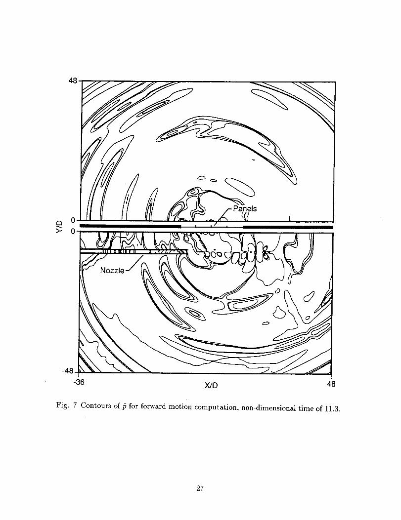
In Figure 7 we show the pressure field in both the jet domain and the radiation domain for a
fixed instant of time for the forward motion computation. The value of the nondimensional
11
time is 11.4. Examination of the radiation domain shows propagation of high frequencies,
characterized by closely spaced contours upstream, whereas the pressure field downstream
is primarily low frequency in nature as seen by the less dense contour distribution. This
is consistent with the integrated intensity in Figure 6b because the higher energy levels at
downstream locations shown in that figure are at lower frequencies. An important feature
of the jet domain is the instability wave, the large scale structure propagating along the jet
axis. The incipient generation of acoustic waves from this instability wave and also from
the nozzle lip can be seen in the figure. Comparison with an analogous figure for the static
computation (not shown) indicates more pronounced radiation downstream for the static
case while with forward motion there is more pronounced propagation upstream, consistent
with Figures 2a and 2b.
4. Conclusion
We have computed the full flow/acoustic/structure coupling for a model of a 4 panel assembly
forced by sound from a jet. The forcing includes both a starter pulse inserted into the jet
flow field, and sound generated from instability waves excited by the starter pulse. We have
computed the far field sound, the panel response, and the panel radiation for two cases: one
involving forward motion of the jet and one involving a static jet. Although our computations
involve excitation of the jet via a pulse starter, instability waves are generated due to the
instability of the jet shear layer which lead to a continual generation of disturbances in the
jet. Thus, those natural sources of jet noise associated with jet instabilities are computed
from the model, although at lower levels than the starter pulse.
The far field sound radiation is heavily influenced by the forward motion. There is an
attenuation of sound downstream, while a forward arc amplification is observed upstream.
These properties are apparent also in the incident pressure on the panels. The incident
pressure is relatively broadband, however low frequencies become more dominant as the
panel location increases downstream of the nozzle exit. There is a significant attenuation in
incident pressure for downstream panels due to forward motion. There is a continual long
time excitation of the panels due to sound generated from instability wave sources in the jet.
The panels act as filters converting the broadband incident pressure to relatively narrow
spectral bands. The panel response is more sustained than the incident pressure, presumably
due to both the small damping of the panels and the continual excitation by instability wave
generated sound. The peak frequencies appear to be insensitive to panel location or to the
presence of forward motion. The amplitude of the low frequencies increases significantly
with downstream distance from the panel. The most pronounced effect of forward motion is
12
to reducethe enhancedlow frequencyresponseof the downstreampanels.
The radiated pressurebearssimilar featuresto thosedue to convectionin the jet domain.
There is a significant low frequencybeamingof soundin the radiation:domain. The primaryeffectof forward motion is to reducethe downstreamradiated sound.
Finally wenote that the responseand radiation of the structure is influencednot only by
the noiseof the jet, but alsoalsoby the boundarylayerflow loadingoverthe structure. Thus,
while the jet noise level on the structure decreaseswith increasesin speed,the boundary
layer flow loadingon the sidewall increases,possiblyleadingto enhancedradiation from the
panels. Thus, theremay be parameterregimeswherethe effectof boundary layers,not yet
incorporated in our model, might qualitatively changesomeof the results.
Acknowledgments
AB was partially supported by NASA Langley Research Center under contracts NAS1-
18605 and NAS1-19480 while in residence at ICASE. Additional support was provided by
NSF grants MMS 91-02981 and DMS 93-01635. JLM and CCF were supported by NASA
Langley Research Center while in residence under a National Research Council Postdoctoral
Research Associateship Award. The authors thank T. D. Norum for helpful discussions and
comments.
References
[1] Bayliss, A., Maestrello, L., and Turkel, E., "On the Interaction of a Sound Pulse With
the Shear Layer of an Axisymmetric Jet, III: Non-Linear Effects", Journal of Sound and
Vibration, Vol. 107, 1986, pp. 167-175.
[2] Bayliss, A. and Turkel, E., "Radiation Boundary Conditions for Wave-Like Equations",
Comm. Pure and Appl. Math., Vol. 33, 1980, 707-725.
[3] Bayliss, A., and Turkel, E., "Far-Field Boundary Conditions For Compressible Flows,"
Journal of Computational Physics, Vol. 48, 1982, pp. 182-199.
[4] Bechert, D.W., and Pfizenmaier, E., "On the Amplification of Broadband Jet Noise by
Pure Tone Excitation," Journal of Sound and Vibration, Vol. 43, 1975, pp. 581-587.
[5] Bushell, K. W., "Measurement and Prediction of Jet Noise in Flight, ", AIAA paper
75-461, 1975.
13
[6]
[7]
[8]
[9]
B. J. Cocking and W. D. Bryce, "Subsonic Jet Noise in Flight Based on Some Recent
Wind Tunnel Tests, " AIAA paper 75-462, 1975.
Crow, S., and Champagne, F., "Orderly Structure in Jet Turbulence," Journal of Fluid
Mechanics, Vol. 48, 1971, pp. 457-591.
Dowell, E. H., "Transmission of Noise from a Turbulent Boundary Layer through a
Flexible Plate into a Closed Cavity", Journal of the Acoustic Society of America, Vol.
46, 1969, pp. 238-252.
Drevet, P., Duponchet, J. P and Jacques, J. R., "The effect of Flight on Jet Noise as
Observed on the Bertin A@rotrain, " Journal of Sound and Vibration, Vol. 54, 1977, pp.
173-201.
[10] Ffowcs Williams, J. E., "The Noise from Turbulence Convected at High Speed, " Philo-
sophical Trans. of the Royal Society, A255, 1963, 469-503.
[11] Gottlieb, D., and Turkel, E., "Dissipative Two-Four Methods For Time-Dependent
Problems," Math. Comp., Vol. 30, 1976, pp. 703]723.
[12] Hayder, M. E. and Turkel, E., "Boundary Conditions for Jet Flow Computations, "
AIAA Paper 94-2195, 1994.
[13] Huerre, P., Monkewitz, P.A., "Local and Global Instabilities in Spatially-Developing
Flows", Ann. Rev. Fluid Mech., Vol. 22, 1990, pp. 473-537.
[14] Kibens, V., "Discrete Noise Spectrum Generated by an Acoustically Excited Jet," AIAA
J., Vol. 18, 1980, pp. 434-441.
[15] Lighthill, M.J., "On Sound Generated Aerodynamically-l, General Theory," Proceedings
of the Royal Society, Vol. A222, 1954, pp. 1-32.
[16] Lilley, G.M., "Theory of Turbulence Generated Jet Noise: Generation of Sound in a
Mixing Region," U.S. Air Force Technical Report AFAPL-TR-7P-53, IV.
[17] Maestrello, L., and Bayliss, A., "Flowfield and Far Field Acoustic Amplification Prop-
erties of Heated and Unheated Jets," AIAA J., Vol. 20, 1982, pp. 1.539-1546.
[18] Mcgreevy, J. L., Bayliss, A. and Maestrelto, L., "Interaction of Jet Noise with a nearby
Panel Assembly", AIAA J., to appear.
14
[19]
[2o]
[21]
[22]
[23]
[24]
[25]
[26]
Maestrello, L., A. Bayliss and E. Turkel, "On the Interaction of a Sound Pulse with the
Shear Layer of an Axisymmetric Jet," Journal of Sound and Vibration, Vol. 74, 1981,
pp. 281-301.
Michalke, A., "Survey on Jet Instability Theory", Progr. Aerospace Sci., Vol. 21, 1984,
pp. 159-199.
Michalke, A., and Hermann G. "On the Inviscid Instability of a Circular Jet With
External Flow", Journal of Fluid Mechanics., Vol. 114, 1982, 343-359.
Michalke, A. and Michel, U., "Prediction of Jet Noise in Flight from Static Tests, "
Journal of Sound and Vibration, Vol. 67, 1979, pp. 341-367.
Norum, T. D., "A Comparison of the Noise Produced by a Small Jet on a Moving
Vehicle with That in a Free Jet, " NASA Technical Paper 1326, 1976.
Norum, T. D. and Shearin, J. G., "Effects of Simulated Flight on the Structure of
Underexpanded Jets, " NASA Technical Paper 2308, 1984.
Ribner, H.S., Dryden Lecture - Perspectives on Jet Noise, AIAA J., Vol. 19, 1981, pp.
1513-1526.
Way, D. J. and Francis, E. M., "The Simulation of Flight Effects on Jet Noise using
Co-flowing Air Streams, " AIAA paper 77-1305, 1977.
15
Far Field Boundary ....
__,exible Panels
1_ 2/ \3---._4 RigidSu,ace
D
t
Nozz,V I \Sta_erPuZ__.__/ . _ I __
.Forward- Motion 60°
90 °
Far Field Boundary
Y
_X
Fig. 1 Computational domain.
16
0 i | i
rn"o
4.0
2.0
0.0
-2.0
-4.0
-6.0
Static
Forward/,_Motion /
. I ' I
0.0 50.0 100.0 150.0
o
Fig. 2a Intensity of far field sound for computations with and without forward motion. Data
taken on a circle of radi_s 30D.
17
10.0 -
dB
Forward/Motion
Static
-8.0 - , i , i J
0.0 50.0 100.0 150.0
o
Fig. 2b Intensity of far field sound for computations with and without forward motion. Data
taken on a circle of radius 30D. Long time behavior of pressure field considered.
18

0.0025
-0.0015
ForwardMotion
Static
Panel 1
i • III
0.0025
-0.0015
Panel 2
LII I lib -- I
i i I i i i | i i
0 5 10 15
t
Fig. 3a Time history of incident ifi for panels 1 and 2 at the panel centers, with and without
forward motion.
19
-0.0015
AStatic
ForwardMotion
Panel 3
0.0025 -
-0.0015
Panel 4
i
0 5 10
Fig. 3b Time history of incident/3 for panels 3 and 4 at the panel centers,
forward motion.
15
with and without
2O
o
Q.09
\ForwardMotion
Static
0
Panel 4
(.3
Q_O3
00
1000 2000
f, Hz.
Fig. 3c Spectra of t5 shown in Figures 3a and 3b for panels 2 and 4.
21
o.ooolJ
>
-0.0001
11
/ForwardM6tion
\Static
Panel 3
0.0001 Panel 4
>
-0.00010 5
Fig. 4a Time history of v at centers of panels 3 and 4,
10 15
with and without forward motion.
22
0
////._
_/////]
/
LX_LLI
l+rii+
+Jq+,11
CO,,p..
O
,r'-
t,-'+,
I
o
©B
o_
B
,...,,..i
©
Vl
vl
23
0.00015
-0.0001
Panel 3
m
i ForwardMotion
0.00015
20.
-0.0001
Panel 4
i I i i
0 5 10 15
t
Fig. 5 Time history of transmitted/_ for panels 3 and 4 at the panel centers_ with and
without forward motion.
24
7e-05
-2e-05
x=-3.2
Forvv.ard
Static .__
I I | i I
-2e-05
x=0.6
! I | I I
7e-05
_o..
-2e-05
°
I ! I |
0 5 10 5
Fig. 6a Time history of/_ in the radiation domain at y = 18D, at 3 different values of x, with
and without forward motion.
25
5.0
ro2D
Static
Forward
Motion/ '_
-10.0
-36 6 48
X/D
Fig. 6b Time integrated intensity of pressure in radiation domain along the line y = 18D,
with and without forward motion.
26
Panels
0 |
X/D 48
Fig. 7 Contours of _5for forward motion computation, non-dimensional time of 11.3.
27
FormApprovedREPORT DOCUMENTATION PAGE OMB No 0704-0188
Pubcreportingburdenforthsco|notionof nformationisestimatedto average1 hourperresponseincludingthetimeforreviewinginstructions,searchingexistingdatasources,gatherngandmaintannl_thedataneeded,andcompetngandrevewngtheco|ectionofinformation.Sendcommentsregardingthisburdenestimateoranyotheraspectof thiscollectionofinformation,includingsuggestionsfor reducingthsburden,toWashingtonHeadquartersServices,Directoratefor informationOperationsandReports,12]5 JeffersonDavisHighway,Suite1204.Arlinglon,VA22202-4302.andtotheOfficeof ManagementandBudget.PaperworkReductonProject(0704-0188),Washington.DC20503.
I. AGENCY USE ONLY(Leaveb/ank) 2. REPORT DATE 3. REPORT TYPE AND DATES COVEREDMay 1995 Contractor Report
4. TITLE AND SUBTITLE 5. FUNDING NUMBERS
RESPONSE OF MULTI-PANEL ASSEMBLY TO NOISE FROM A
JET IN FORWARD MOTION
6. AUTHOR(S)
A. Bayhss, L. MaestreUo, J. L. McGreevy, C. C. Fenno, Jr.
7. PERFORMING ORGANIZATION NAME(S) AND ADDRESS(ES)
Institute for Computer Applications in Science
and Engineering
Mail Stop 132C, NASA Langley Research Center
Hampton, VA 23681-0001
9. SPONSORING/MONITORING AGENCY NAME(S) AND ADDRESS(ES)
National Aeronautics and Space Administration
Langley Research Center
Hampton, VA 23681-0001
C NASl-19480
WU 505-90-52-01
8. PERFORMING ORGANIZATIONREPORT NUMBER
ICASE Report No. 95-41
10. SPONSORING/MONITORINGAGENCY REPORT NUMBER
NASA CR-198164
ICASE Report No. 95-41
11. SUPPLEMENTARY NOTES
Langley Technical Monitor: Dennis M. Bushnell
Final ReportTo appear at First CEAS/AIAA Aeroacoustics Conference; To be submitted to AIAA Journal
12a. DISTRIBUTION/AVAILABILITY STATEMENT 12b. DISTRIBUTION CODE
Unclassified- Unlimited
Subject Category 34
13. ABSTRACT (Maximum200 words)A model of the interaction of the noise from a spreading subsonic jet with a 4 panel assembly is studied numerically
in two dimensions. The effect of forward motion of the jet is accounted for by considering a uniform flow field
superimposed on a mean jet exit profile. The jet is initially excited by a pulse-like source inserted into the flowfield. The pulse triggers instabilities associated with the inviscid instability of the jet shear layer. These instabilities
generate sound which in turn serves to excite the panels. We compare the sound from the jet, the responses of the
panels and the resulting acoustic radiation for the static jet and the jet in forward motion. The far field acoustic
radiation, the panel response and sound radiated from the panels are all computed and compared to computations
of a static jet. The results demonstrate that for a jet in forward motion there is a reduction in sound in downstreamdirections and an increase in sound in upstream directions in agreement with experiments. Furthermore, the panel
response and radiation for a jet in forward motion exhibits a downstream attenuation as compared with the static
case.
14. SUBJECT TERMSaeroacoustics; structural dynamics; sound radiation
17. SECURITY CLASSIFICATION 18, SECURITY CLASSIFICATIOEOF REPORT OF THIS PAGEUnclassified Unclassified
NSN 7540-01-280-5500
19. SECURITY CLASSIFICATIONOF ABSTRACT
15. NUMBER OF PAGES
29
16. PRICE CODE
A03
20. LIMITATIONOF ABSTRACT
Standard Form 298(Rev. 2-89)PrescribedbyANSIStd.Z3_18298-102