Embed Size (px)
Citation preview

Portland State University Portland State University
PDXScholar PDXScholar
Dissertations and Theses Dissertations and Theses
7-1973
Response of orthotropic bridge decks to highway Response of orthotropic bridge decks to highway
loadings loadings
Harry Morris Rexin Portland State University
Follow this and additional works at httpspdxscholarlibrarypdxeduopen_access_etds
Part of the Civil Engineering Commons and the Structural Engineering Commons
Let us know how access to this document benefits you
Recommended Citation Recommended Citation Rexin Harry Morris Response of orthotropic bridge decks to highway loadings (1973) Dissertations and Theses Paper 1611 httpsdoiorg1015760etd1610
This Thesis is brought to you for free and open access It has been accepted for inclusion in Dissertations and Theses by an authorized administrator of PDXScholar Please contact us if we can make this document more accessible pdxscholarpdxedu
AN ABSTRACT OF THE THESIS OF Harry Morris Rexin for the Master of
Science in Applied Science presented July 27 1973
Title Response of Orthotropic Bridge Decks to Highway
Load ings
APPROVED BY MEMBERS OF THE THESIS COMMITTEE
This thesis documents the fabrication testing techniques and
response of a plastic scale model of an orthotropic bridge deck To
economically investigate a two-lane steel brfdge deck plastic AcrylicR
was used as a model ing material_ Welds were sImulated with dichloroshy
methane a capillary action sorvent and PS-30 a pDlymerizable
cement Deflections were measured with laboratory dial guages while
strains were monitored with strain guages mounted on the deck
The response of the deck to AASHO vehicle axle loads was comshy
pared with a discrete element computer program used to analyze
orthotropic bridge decks continuous over flexible supports Results
indicate good correlation between measured and computed values for
deflection and strains
j
RESPONSE OF ORTHOTROPIC BRIDGE DECKS
TO HIGHWAY LOADINGS
by
HARRY MORRIS REXIN
A thesis submitted in partial fulfillment of the requirements for the degree of
MASTER OF SCIENCE
in
APPLIED SCIENCE
Portland State University
July 1973
TO THE OFFICE OF GRADUATE STUDIES AND RESEARCH
The members of the Committee approve the thesis of
Harry Morris Rexin presented July 27 1973
APPROVED
Nan-Teh Department of Science
Davi
Ju I Y 27 1973
31 1M AVgtJ 01
ACKNOWLEDGMENTS
Without the cooperation guidance and patience of the entire
Applied Science faculty and staff the completion of this thesis would
have been impossible lowe particular thanks to Dr Nan-Teh Hsu for
his efforts to make it economically possible for me to continue my
education Special gratitude is also expressed to Dr Hacik Erzurumlu
my supervising professor for suggesting the topic of this investigashy
tion and for the constructive criticism and encouragement he provided
throughout the project lowe Dr Franz N Rad thanks for the time
he took to discuss and suggest laboratory techniques during the length
of this project Thanks are extended to Dr Selmo Tauber for introshy
ducing me to differential equations To M Johnson and the Bonneville
Power Administration I wish to express my grateful appreciation for
their assistance with the computer program
Portland State University Harry Morris Rexin Portland Oregon July 1973
- - - - - - TABLE -OF CONTENTS -- - shy
ACKNOWLEDGMENTS
PAGE
iv ~
NOMENCLATURE vii
LIST OF TABLES ix
LIST OF FIGURES x
CHAPTER
I INTRODUCTION
Definitions 1
II EXPERIMENTAL PROGRAM
III FABRICATION
Historical Development 1
Purpose of Investigation 5
Material 7
Equations of Similitude 7
Loading 10
Strain and Deflection Gauges 11
Testing Procedure 12
Splices bull 14
Gluing Techniques 15
Cutting 16
Ribs 17
Floor Beams 18
Assembly of the Orthotropic Deck Model 18
Supports and Lo~ding Beam bull bull 20
~
vi
CHAPTER PAGE
IV TEST RESULTS
The Computer Model 21
Idealized Sections 22
Calculated Versus Observed Deflections and Strains 23
(a) Deflections 23
(b) Strains 26
V CONCLUSIONS AND RECOMMENDATIONS
Conclusions 29
Recommendations 30
REFERENCES 31
FIGURES 33
TABLES 57
APPENDIX Ia 66
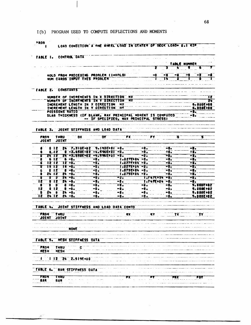
APPENDIX Ib 68
APPENDIX II 70
VITA 75
A m
A P
D x
D Y
E m
E P
H
hx
h y
L m
L P
P (xy)
P P
P m
Sf
Sp
w
Um
6 p
NOMENCLATURE
= Area of model
= Area of prototype
= Flexural rigidity of orthotropic plate per unit width in the x-direction
= Flexural rigidity of orthotropic plate per unit width in the y-direction
= Modulus of elasticity for model material
= Modulus of elasticity for prototype material
= Effective or reduced torsional rigidity of orthotropic plate per unit width
= Increment length in the x-direction in the discrete element model
= Increment length in the y-direction in the discrete element model
= Model lengths
= Prototype lengths
= Magnitude of distributed load
= Load on prototype
= Load on model
= Strain scale factor
= Load scale factor
on plate at location (xy)
= Vertical displacement of orthotropic plate
= Model deflections
= Prototype deflections
viii
=Strains in modelEm
=Strains in prototypepoundp =Length of small fiber on the tensile side of a beam
section
5 =Model stresses m
= Prototype stressesESp
~~ bull --~ - ~ ~~~
LIST OF TABLES
PAGETABLE ~
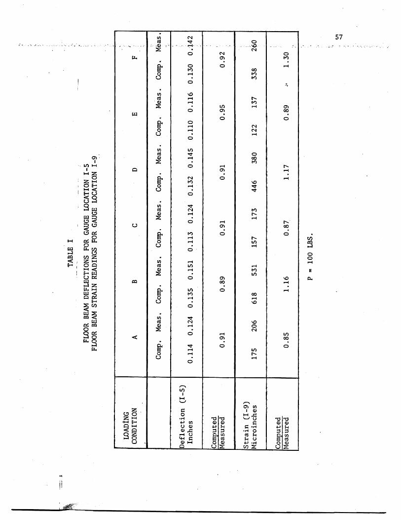
I Floor Beam Deflections for Gauge Location 1-5
and Strain Readings for Gauge Location 1-9 57
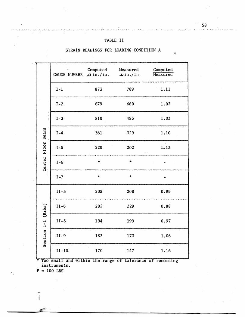
II Strain Readings for Loading Condition A 58
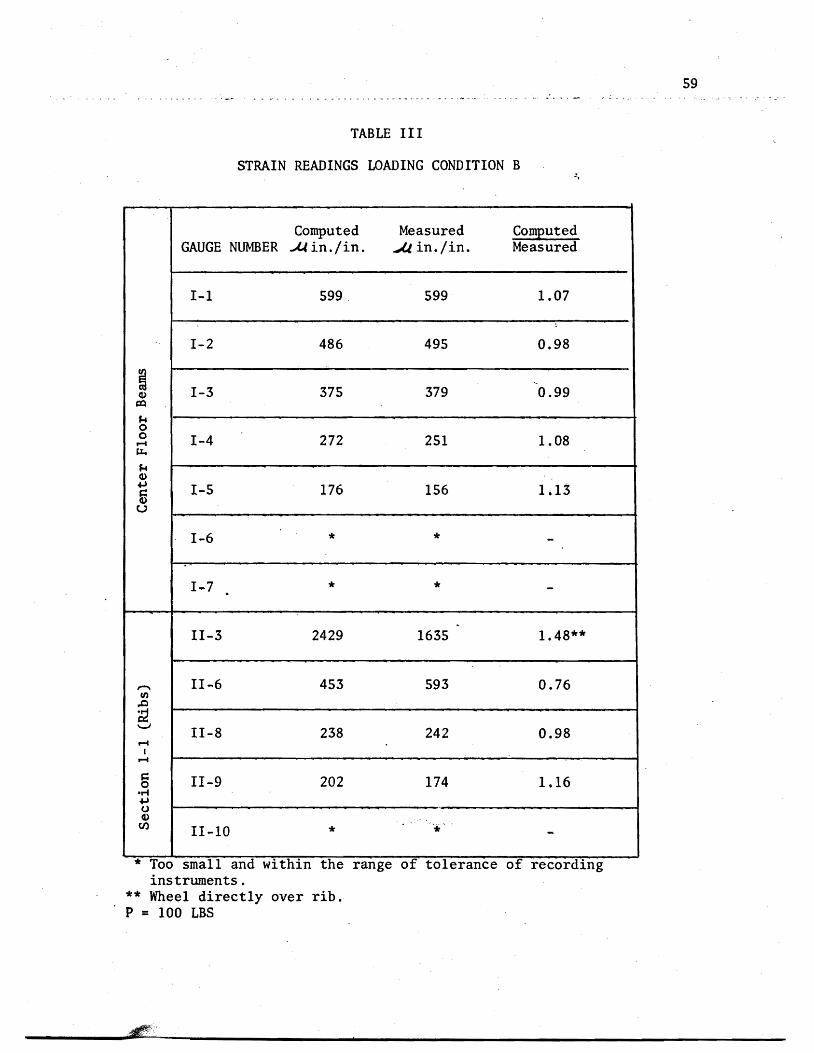
III Strain Readings for Loading Condition B middot 59
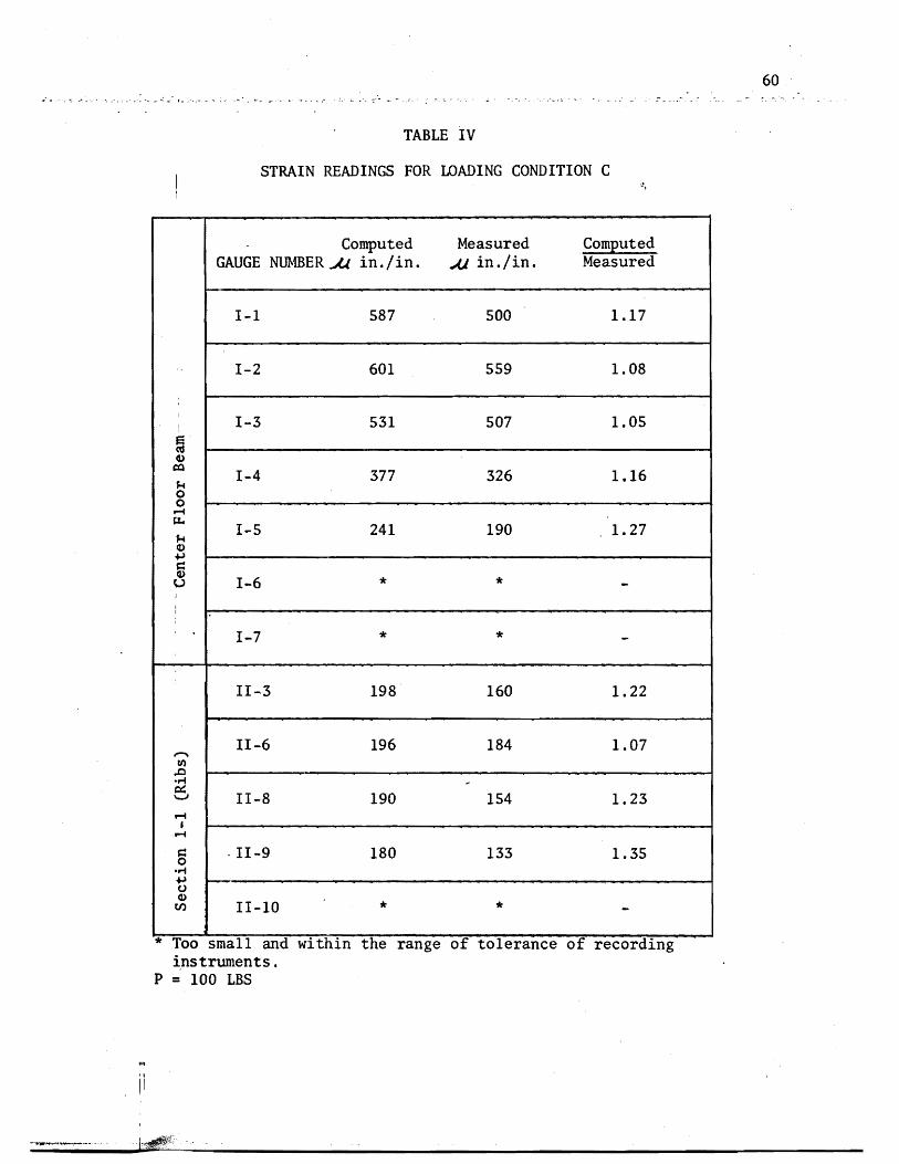
middotIV Strain Readings for Loading Condition C 60
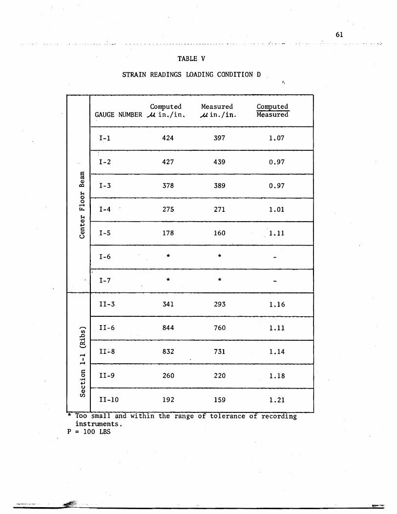
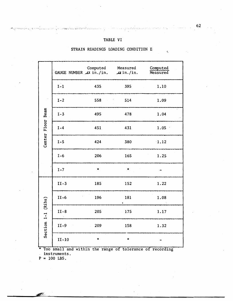
V Strain Readings for Loading Condition D bull 61middot VI Strain Readings for Loading Condition E 62middot middot
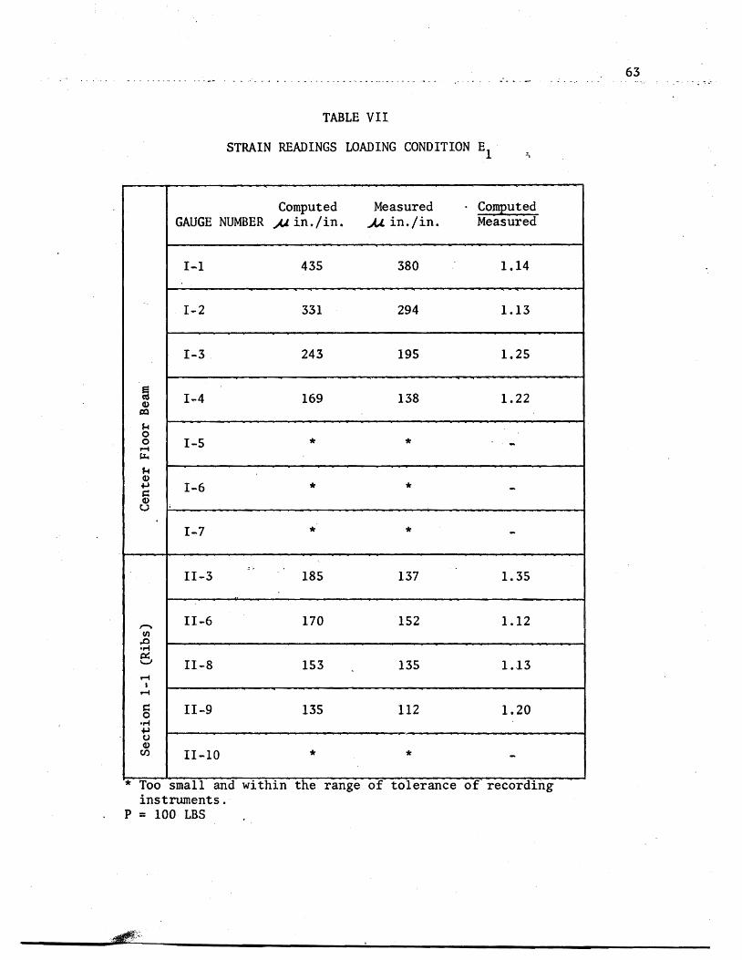
VII Strain Readings for Loading Condition El middot middot 63
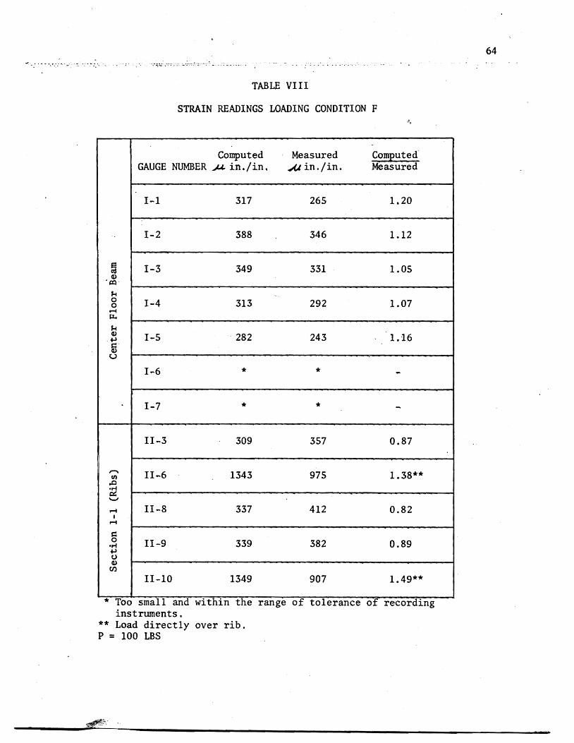
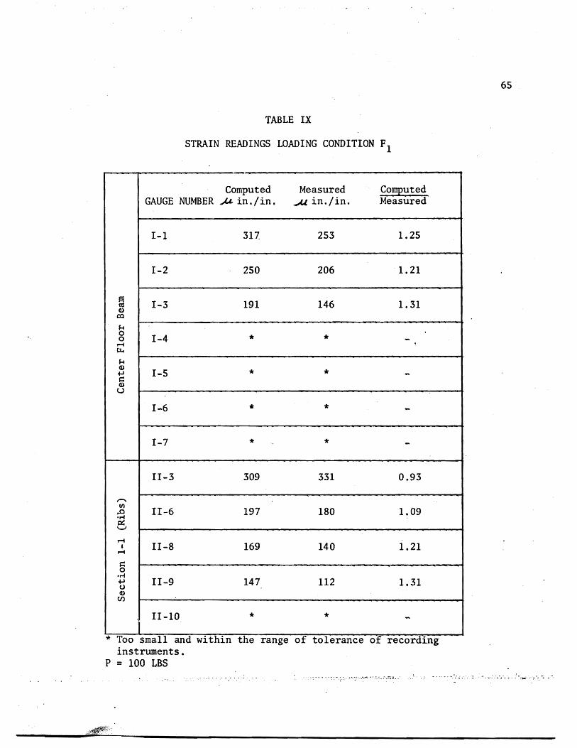
VIII Strain Readings for Loading Condition F middot 64middot middot IX Strain Readings for Loading Condition Fl middot middot 65
illmiddot
JI~T QF _fJG1J~~~
FIGURE
11 Orthotropic Steel Plate Deck with Closed Ribs
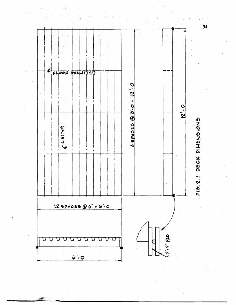
21 Deck Dimensions
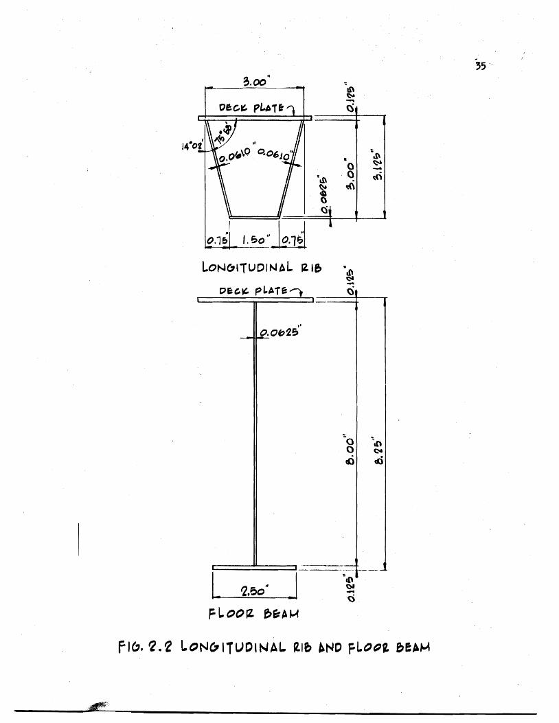
22 Longitudinal Rib and Floor Beam
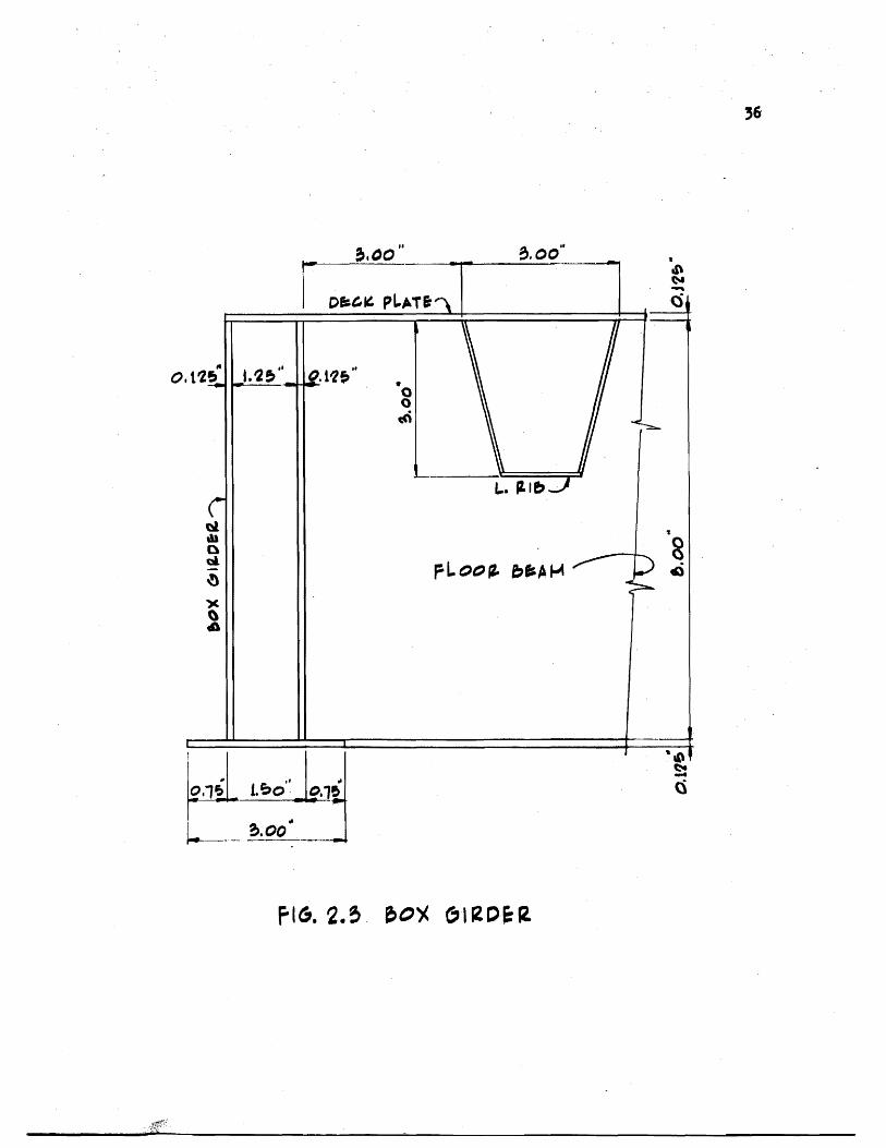
23 Box Girder
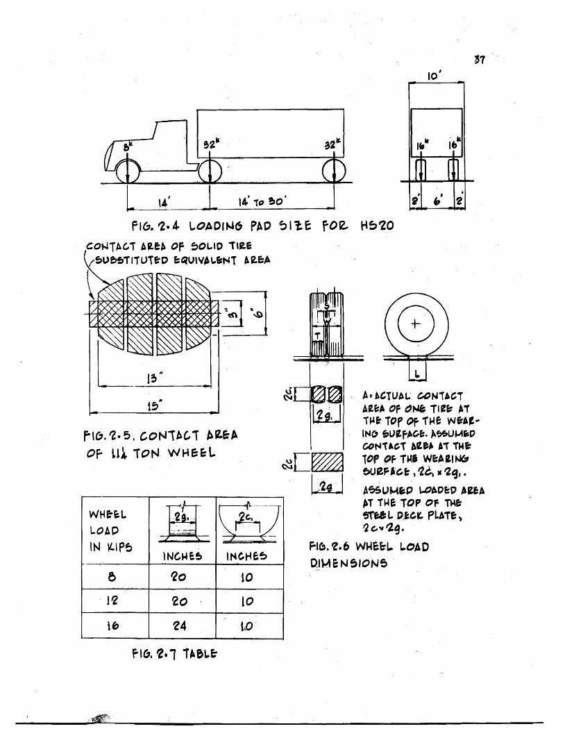
24 Loading Pad Size for HS20 Vehicle
2S Contact Area of 11-14-Ton Wheel
26 Wheel Load Dimensions
27 Contact Area for Wheels Directly on Deck
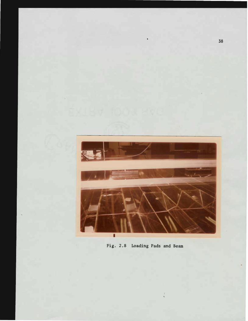
28 Loading Pad and Beam
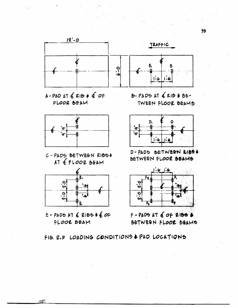
29 Loading Conditions and Pad Locations
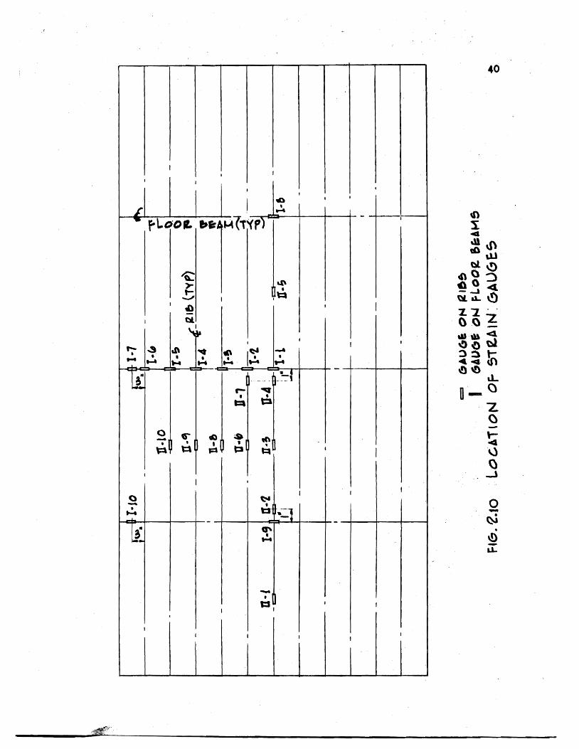
210 Location of Strain Gauges
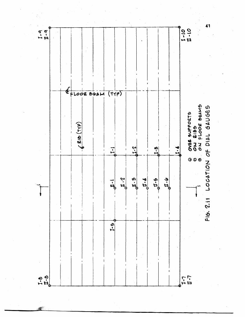
211 Location of Dial Gauges
212 Test Set-Up During Testing
213 Bridge Used in Deflection Measurements
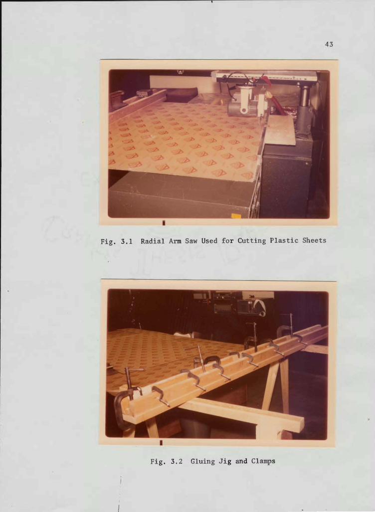
31 Radial Arm Saw Used for Cutting Plastic Sheets
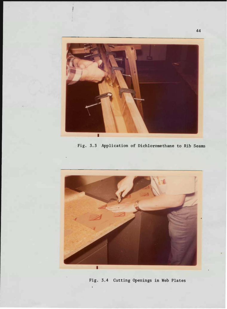
32 Gluing Jig and Clamps
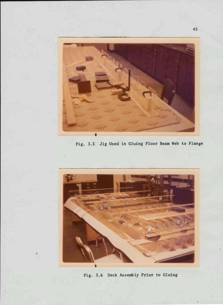
33 Application of Dichloromethane to Rib Seams
34 Cutting Openings in Web Plates
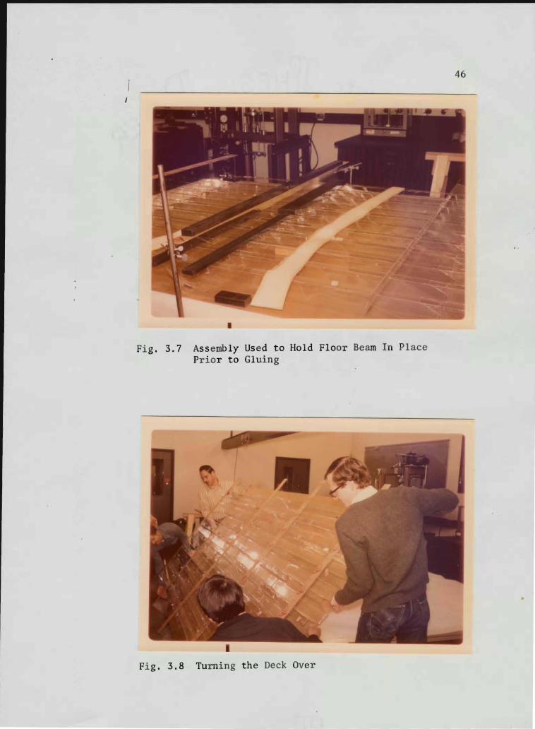
3S Jig Used in Gluing Floor Beam Web to Flange
36 Deck Assembly Prior to Gluing
37 Assembly Used to Hold Floor Beam in Place
Prior to Gluing
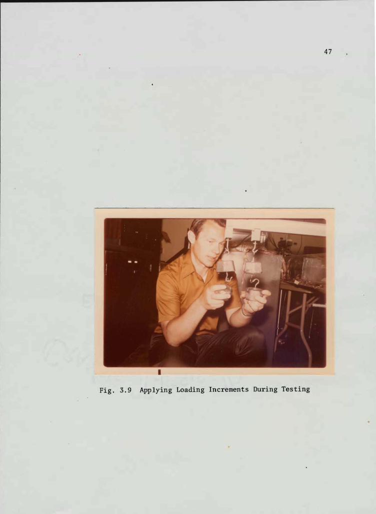
38 Turning the Deck Over 39 Applying Loading Increments
PAGE
33 ~J
34
3S
36
37
37
37
37
38
39
40
41
42
42
43
43
44
44
4S
4S
46
46
47
~~
xi
FIGURE PAGE
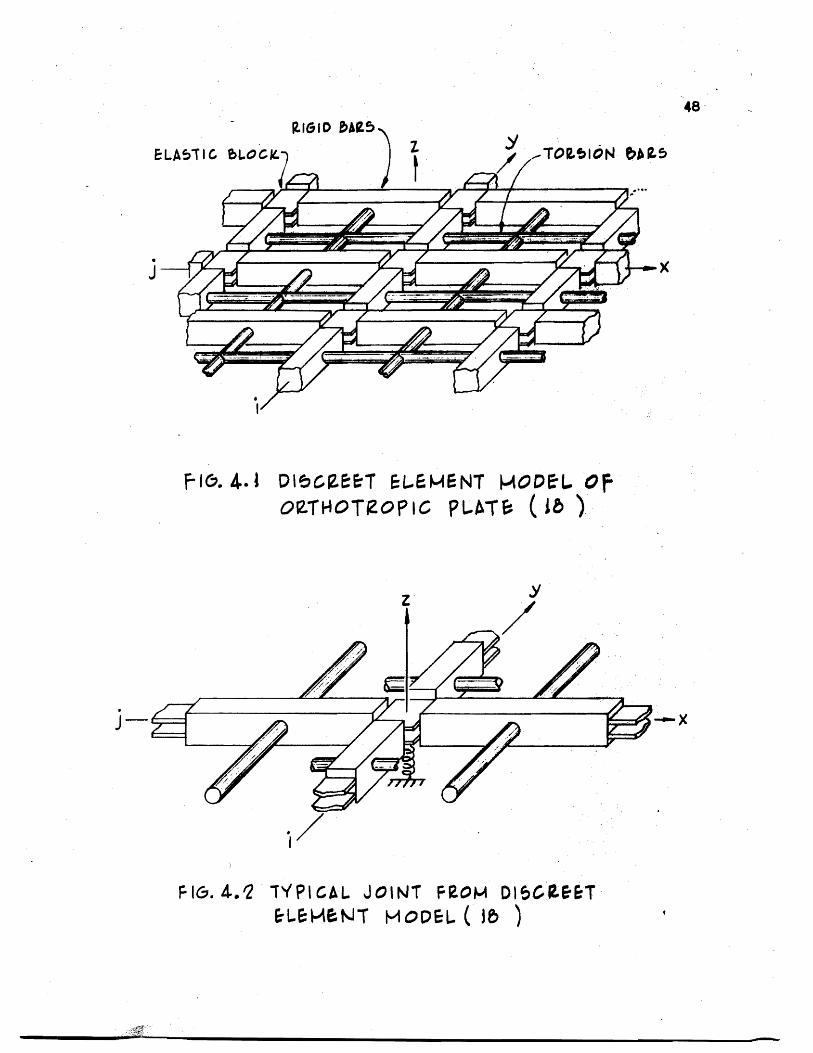
41 Discrete Element Model of Orthotropic Plate 48
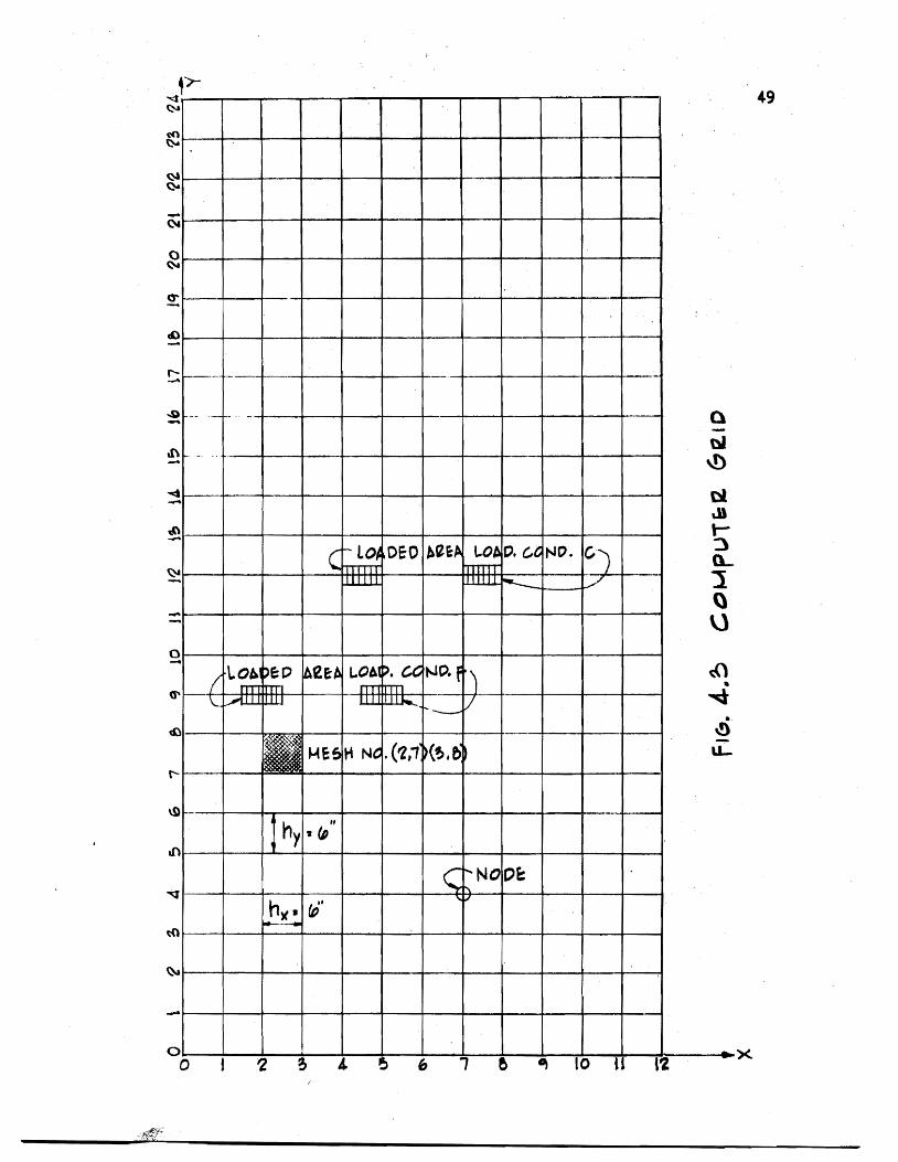
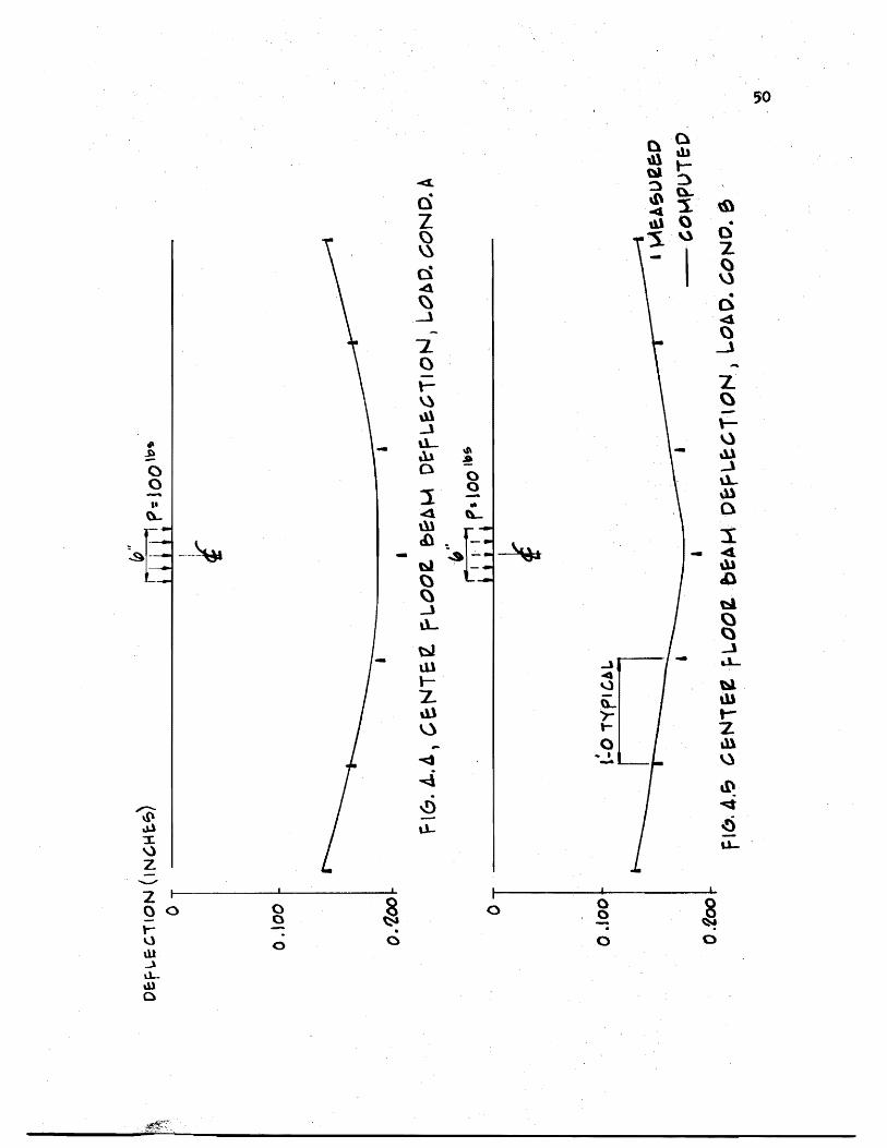
42 Typical Joint From Discrete Element Model 48 middot middot middot 43 Computer Grid 49 middot middot middot middot middot middot middot middot middot middot middot middot middot middot middot middot 44 Center Floor Beam Deflection Loading Condition A 50
45 Center Floor Beam Deflection Loading Condition B 50
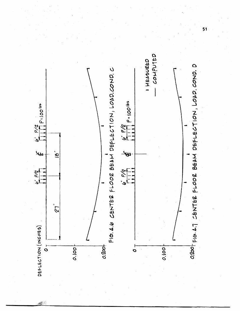
46 Center Floor Beam Deflection Loading Condition C 51
47 Center Floor Beam Deflection Loading Condition D 51
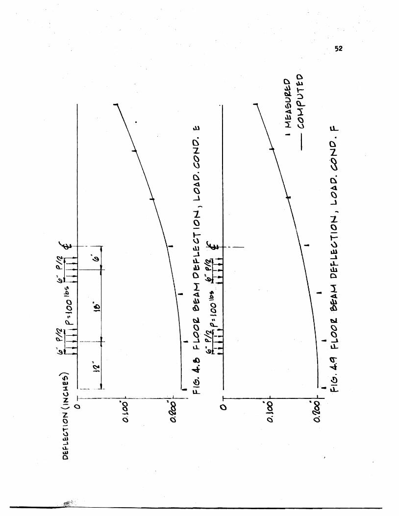
48 Center Floor Beam Deflection Loading Condition E 52
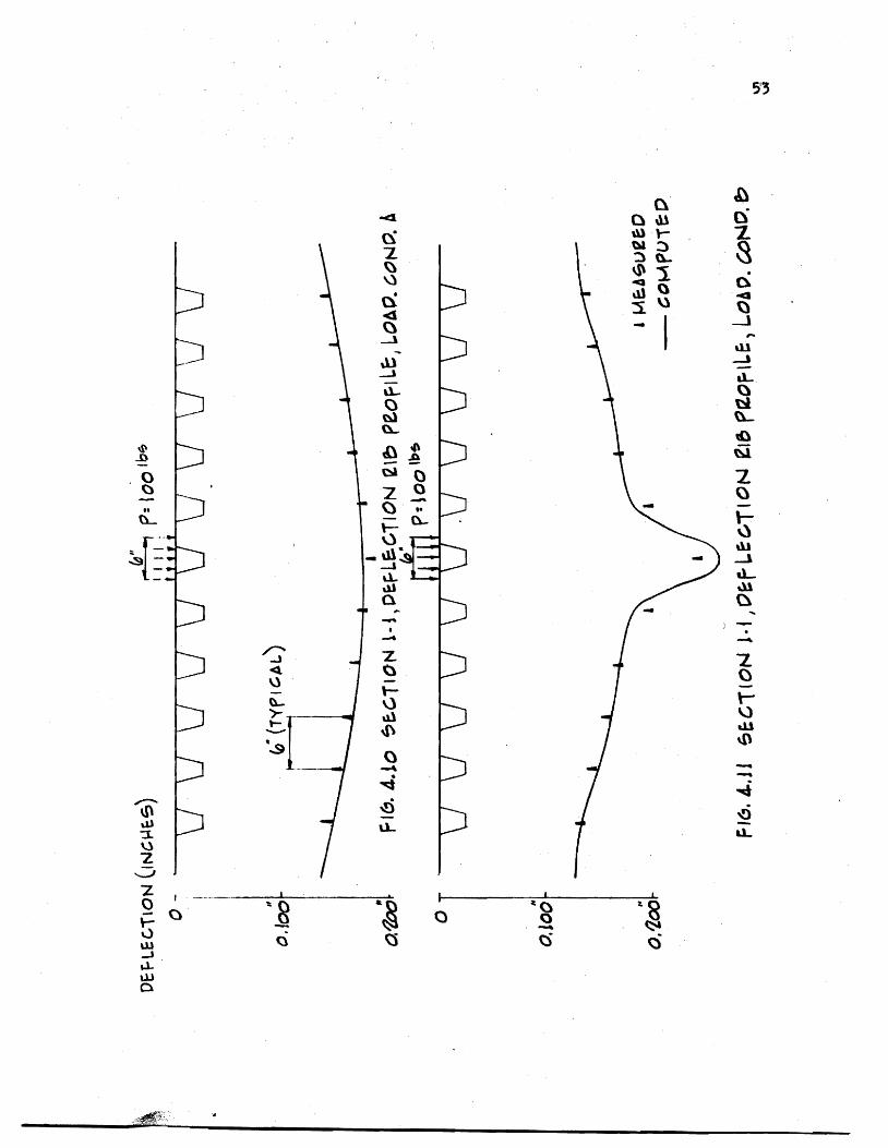
49 Center Floor Beam Deflection Loading Condition F 52middot middot middot middot 410 Rib Deflection Profile Section 1middot1 Loading
Condition A 53middot middot middot middot middot middot middot middot middot middot middot middot middot middot middot middot middot middot middot middot 411 Rib Deflection Profile Section 1-1 Loading
Condition B bull 53middot middot middot middot middot middot middot middot middot middot middot middot middot middot middot middot middot middot middot middot 412 Rib Deflection Profile Section 1-1 Loading
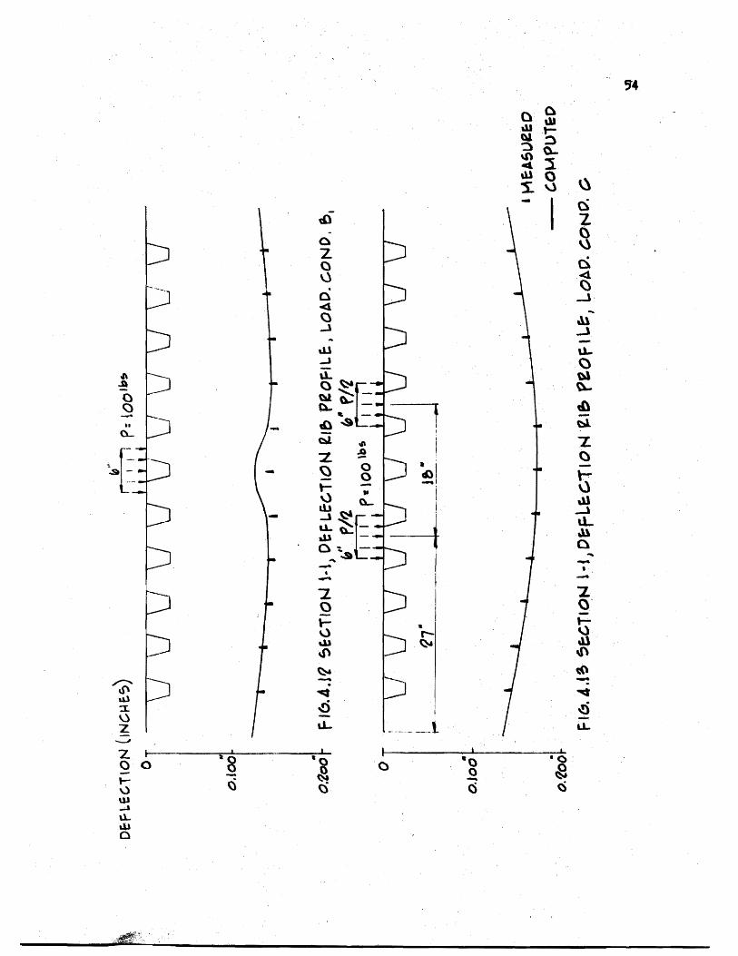
Condition Bl 54middot middot middot middot middot middot middot middot middot middot middot middot middot middot middot
413 Rib Deflection Profile Section 1-1 Loading
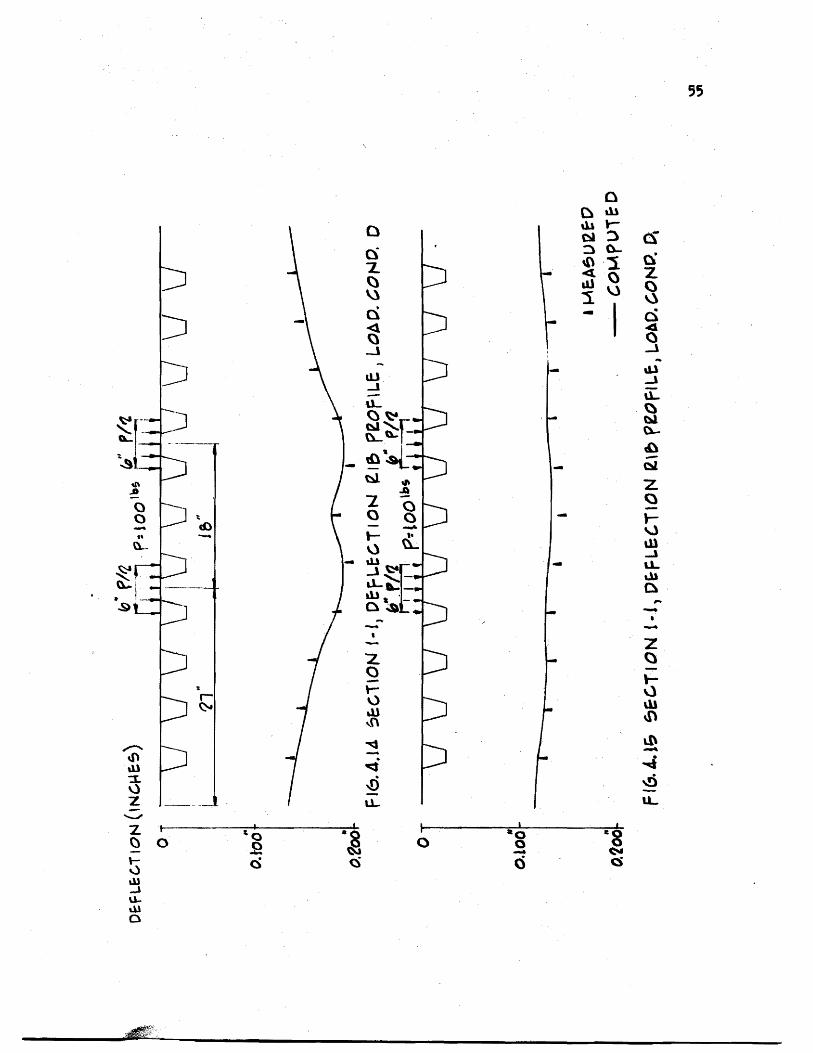
Condition C 54middot middot middot middot middot middot middot middot middot middot middot middot middot middot 414 Rib Deflection Profile Section 1-1 Loading
Condition D 55middot middot middot middot middot middot middot middot middot middot middot middot middot middot middot middot middot 415 Rib Deflection Profile Section 1-1 Loading
Condition D1 55middot middot middot middot middot middot middot middot middot middot middot middot middot middot middot middot middot 416 Rib Deflection Profile Section 1-1 Loading
l
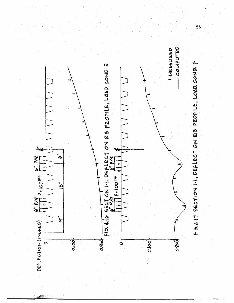
Condition E 56middot middot middot middot middot middot middot middot middot middot middot middot middot middot middot middot 417 Rib Deflection Profile Section 1-1 Loading
- Condition -p - - -- - ~ ~ - - ~~ ~ - 56 M ~ bullbullmiddot middot middot middot middot middot middot middot middot 6 ii~
CHAPTER 1
INTRODUCTION
Definitions
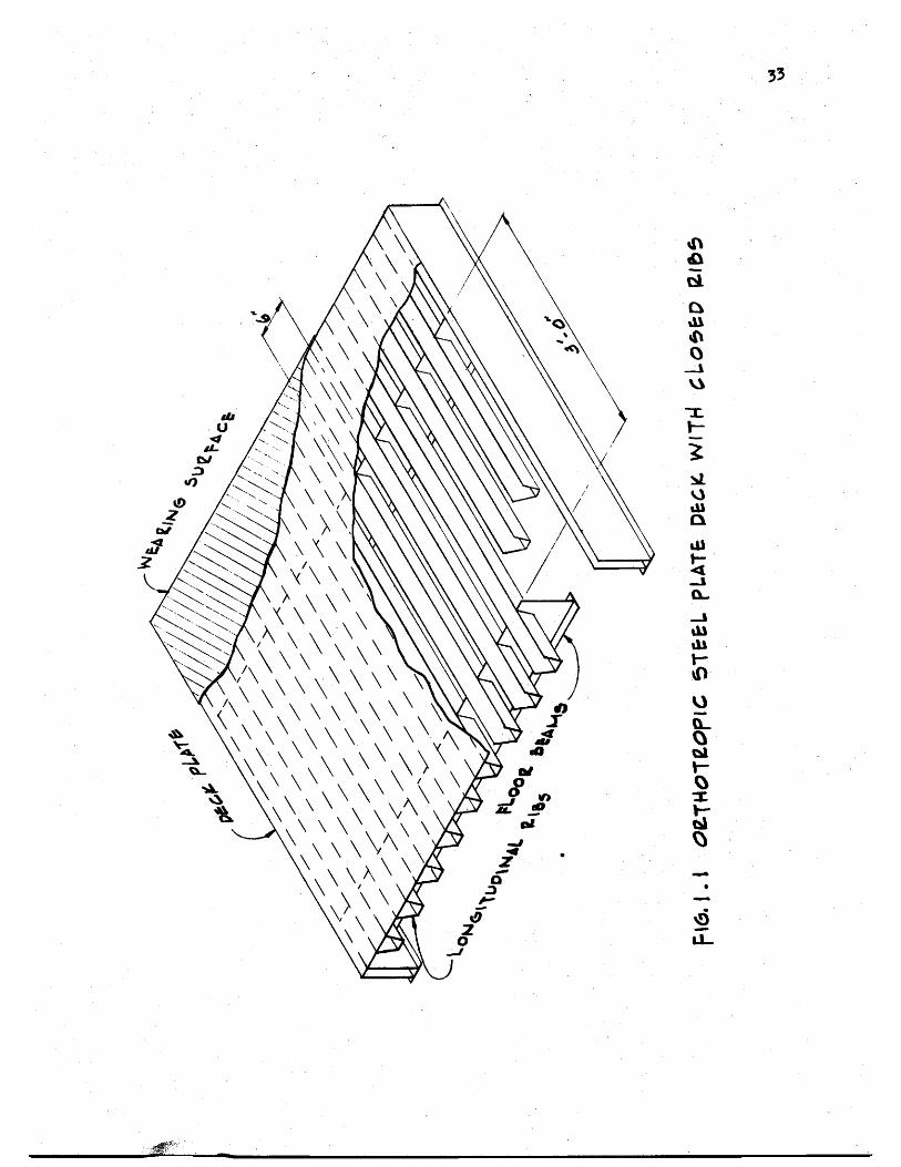
Generally an orthotropic bridge deck consists of a flat
thin steel plate stiffened by a series of closely spaced longitushy
dinal ribs at right angles to the floor beams (23) (Fig 11)
The term orthotropic the abbreviated combination of orthogonalshy
anisotropic describes a continuum that has varying elastic propershy
ties in either two (plates) or three mutually perpendicular directions
Orthotropy if due to the physical structure of the material
is called natural orthotropy An example of this would be wood
which has different stiffnesses parallel and perpendicular to the
grain due to the orientation of its cells Technical orthotropy is
a term used in structural engineering that describes (a) structural
elements composed of a single material which have different rigidities
in two orthogonal directions owing to their geometry and (b) strucshy
tural elements composed of two or more materials The structural
elements dealt with in this investigation fall in category (a) and
will be referred to simply as orthotropic
Historical Development
In the conventional bridge deck design the following members
are assumed to act independently to carry the vertical loads
Numbers listed refer to references at the end of this thesis
2
(a) A slab which transmits the loads to a series of longitudinal
beams called stringers or ribs (b) Stringers which are carried by
floor beams (c) Floor beams supported by the main girders (d) Main
girders which transmit their load to the bridge supports The main
disadvantage of this type of design lies in the fact that each element
is thought to fulfill a separate function resulting in wasted material
and an increase in the dead weight of the bridge Actually the above
elements of the bridge system resist the load as an integral unit when
a load is placed at any point on the bridge the decking and floor
beams distribute it to the main girders in proportion to the relative
rigidities of the different parts of the structure
The first bridge that utilized the deck plate stringers (ribs)
and floor beams acting together was an overpass at Jungingen Germany
in 1934 true economy however was not achieved because the deck and
main carrying members were analyzed as separate elements The main
advantage was its shallow depth which gave it a slender appearance
During the same decade the American Institute of Steel Construction
was experimenting with a similar type of deck construction known as the
battledeck floor It was from tests conducted at Lehigh University on
scale models that a greater reserve strength than that predicted by
bending theory was found in the deck plating (23) It was not until
after World War II when due to a shortage of steel and a need to
replace many long span bridges in Germany that the full economic
realization of orthotropic design was recognized The deck was
3
considered to fully participate in the sttess of the main carrying
members of the bridge
The first bridge using this concept was the Kurpfalz Bridge over
the Neckar River in Mannheim Germany which was opened to traffic in
1950 (19) Other important l~ng-span bridge structures followed in
quick succession But it was not until 1960 that work was begun on
the first orthotropic deck bridge in the Western hemisphere with the
Port Mann Bridge over the Fraser River in Vancouver BC Canada (13)
In the United States the Poplar Street Bridge over the Mississippi
River in St Louis Missouri (22) built in 1966 spurred interest in
orthotropic bridge construction and other bridges of the same type
followed Major orthotropic bridges recently completed in the United
States are the San Mateo-Hayward Bridge across South San Francisco
Bay (8) the San Diego-Coronado Bridge (1) and the Fremont Bridge in
Portland Oregon (14) which is nearing ~ompletion
Long before the advent of orthotropic deck bridges theoretical
studies were conducted on orthotropic plates The first mathematician
to address the problem of anisotropic bodies was Cauchy (4) who in
his paper published in 1828 gave generalized elasticity equations
The first application of the theory of anisotropy to a structural
element such as a plate was attempted by Gehring (11) in 1860
Other theoretical investigations were carried out by Boussinesq (3)
1879 Voigt (25) 1910 and Geckeler (10) 1928 The first comprehensive
4
tteatment of orthotropic plates was presented by Huber (16) in 1914
It was from his works that the solution to orthotropic plate problem
was developed The following equation known as Hubers equation
gives the relationship between deflection and loading
b 4 4 w _ + D r w = P(xy) [11]+ 2H~ ex uy Yb y
4
This is a non-homogenous differential equation because the deflection w
does not appear in the function P(xy) D D and H are the rigidshyx y
ity coefficients while the function P(xy) is the loading intensity at
any point The solution involves first solving the corresponding
homogenous differential equation where P(xy) = 0 and superimposing
this general solution with a particular solution of the non-homogenous
equation The result will vary depending on the relations between the
three rigidities D D and H x y
To treat a stiffened plate as an equivalent orthotropic plate
an assumption is generally made that the spacing of ribs is small
relative to their length between supports In 1946 Guyon (12) proposed
a method of applying orthotropic plate theory to a bridge deck this
was followed by Massonnet (17) who took into account the effect of
torsional rigidity It was in conjunction with the design of the
Cologne-Muelheim Bridge in 1951 that Cornelius (6) first applied
Hubers equation to the problem of computing stresses The most successshy
ful method of th~ application of Hubers equation was developed by
5
Pelikan and Esslinger (21) This method was adopted in the AISC Design
Manual for Orthotropic Steel Plate Deck Bridges (2)
Although there appears to be an abundance of theoretical studies
on the subject of orthotropic plates experimental investigations
known to date most of which have been conducted in conjunction with
the construction of major orthotropic bridges are somewhat limited
Such tests have been carried out in different countries primarily on
prototypes To overcome both physical and economic difficulties of
testing prototypes model tests on bridge structures have been successshy
fully utilized by several investigators Heins and Hails (15) used a
curved stiffened plate model to show the validity of the mathematical
model and the resulting computer program for a bridge with curved
girders Naruoka Okabe and Hori (20) made an experimental study
of an orthotropic bridge model with torsionally soft ribs to check
a proposed mathematical model Troitsky and Azad (24) built and
tested a plastic scale model of an orthotropic box girder with open
ribs
Purpose of Investigation
A two year-study of the behavior of torsionally stiff orthotropic
decks was conducted recently by Erzurumlu and Toprac (9) The
experimental program consisted of prototype tests of deck panels
simply supported by unyielding floor beams In contrast this thesis
evaluates the response of a multiple panel deck supported by flexible
floor beams In order to establish further confidence in the discrete
6
element model and computer program proposed by above investigators
to simulate highway loadings and to keep experimental costs to a minishy
mum a scale model of plastic was considered to be the most appropriate
The object of this investigation may be summarized as follows
(1) To develop adequate scale modelS of plastic for
orthotropic steel bridge decks continuous over flexible
floor beams
(2) To verify the adequacy of a discrete element computer
program (18) used in Reference 9 by subjecting the
bridge model to AASHO vehicle loadings
CHAPTER 2
EXPERIMENTAL PROGRAM
The dimensions of the model to be investigated were chosen so
that a two-lane steel orthotropic bridge deck would be simulated
The material sizes were selected on the basis of availability of
plastic sheets Although the primary objective of the investigation
was not to simulate an existing deck the dimensions as shown in
Figs 21 through 23 with the exception of the box girder fell
very near those of the Poplar Street Bridge (22) and the Fremont
Bridge (14) when a scale factor of 4 was applied
Material
The material used was AcryliteR an acrylic sheet manufactured by
the American Cyanamid Company in Wayne New Jersey Its chemical name
is poly(methylmethacrylate) The modulus of elasticity was determined
by standard coupons taken from the plastic sheets used in fabricating
the deck Its average value was found to be 394 ksi The Poissons
ratio was taken as 035 as suggested by the manufacturer
Equations of Similitude
Principles of similitude governing structural models are well
documented (26) Structural models may be classified as direct and
indirect Direct models are made of the same material as the prototype
and simulate the true response of the prototype including ultimate
strength On the other hand indirect models simply represent the
8
response of the prototype within the elastic range and need not be
fabricated of the same material as the prototype
To illustrate the basic relationship governing the similitude of
geometry and loading the following eqUations are provided for the sake
of clarity By using a scale factor of 4 all lengths in the deck model
are one-fourth the lengths of the prototype
L Lm =-pound
4 [21]
where Lm = length in the model
L = length in the prototypep
Using the same reasoning model deflections are one-fourth the protoshy
type deflections
= L~p [22] ~-~ m 4
where 6 m and L~ p are deflections in the model and prototype respecshy
tively
Strains are related by the strain scale factor
Sf = Epl Em
where Sf = strain scale factor
E = strain in prototypep
E = strain in model m
Considering the deformation lj of a small fiber of some length J on
the tensile side of a beam section
9
[23]6 p = ~ Jp
6 m = fm 1m [24
By substituting Eqs pound21] and [22] into [24]
L ~= [2 S]tm --t4
The substitution of Eq [23] into Eq [25] gives
[26]ip = ~
Therefore the strain scale factor equals one in a true model where
strains at corresponding points in model and prototype are equal
provided the loads are scaled properly
~
Since SE = ~ = 1 loads can be scaled using the following relationshy
ships
p = 6 AP P P
~ =~ and m E m
A EA = m (4) 2
where A and A = areas of the model and prototype respectivelym p
E and E = the modulus of elasticity of model and prototype m p respectively
6 and 6 = the stress in the model and prototype respectivelym p
P = load on the prototyPep
10
From which
[27]Pp = [CAm)4J [Om ~J Since P = (5 A m mm
P E S =-E = (4)2 -pound [28]p P E m m
where S = load scale factorp
P = load on the model m
If the modulus of elasticity of steel is 29000 ksi and that of plastic
is 394 ksi then
P P = -Es = (0000849)P [29]m pp
This means that a load of 100 lbs used in the model test is equivashy
lent to a 1178 k load on the prototype The total weight of one H520
truck is 72 k (Fig 24) (1)
Loading
Scale models of actual trucks would require a minimum length of
7 ft on the deck Because the length of model deck was only 12 ft it
was considered sufficient to simulate only single whe~l and axle loads
The size of t~e loading pad was taken as 6 in by 25 in which is
equivalent to an AASHO HS20 truck wheel contact area (Figs 25 26
and 27) This area is determined assuming that the tire is in direct
11
contact with the deck plate without considering pavement thus represhy
senting the worst condition for local stresses in the vicinity of the
loaded area The applied load was transmitted to the deck through a
l2-in neoprene pad and a steel plate as shown in Fig2S A summary
of all loading positions is shown in Fig 29
Strain and Deflection Gauges
The strain gauges used were Micro-Measurements Inc EA-06-2S0BGshy
120 which are general purpose gauges intended for static and dynamic
stress analysis To overcome the heating problem and the resulting
errors caused by the poor heat sink quality of plastic a method of
pulsing which will be discussed subsequently under testing procedure
was used
The positions of the strain and deflection gauges are shown in
Figs 210 and 211 respectively The gauge installation procedure
as suggested by the manufacturer was followed closely After installashy
tion a piece of cellophane tape was placed over each gauge to protect
the lead wires All lead wires were cut at equal lengths (12 ft) to
ensure that variable lead resistance would not be a factor during
testing The strain gauges were monitored by a Datran II strain recordshy
ing system which consists of a Model 1330 lO-channel scanner a Model
321 strain indicator and a Franklin 1200 Hi-Speed Printer (Fig 212)
A gauge factor of 210 was used for all strain gauges
Deflections of the deck were measured with dial gauges to an
accuracy of 0001 inch The gauges were mounted on a bridge supported
12
on two sides by metal stands (Fig 213) Support deflections also
were monitored and used later to obtain corrected span deflections
Testing Procedure
In testing ~odels madamp of plastic two problems are encountered
which are not significant in metal modelS (a) As mentioned earlier
the temperature of the strain gauges increases due to the insulating
characteristics of the plastic (b) A significant amount of creep occurs
To avoid heating strain gauges weteonly activated during an
actual reading In this manner the presence of current in each circuit
was limited to just a fraction of a second To efficiently take the
readings the Franklin 1200 Hi-Speed Digital Printer was connected to
the strain indicator thereby enabling all ten channels to be read and
recorded within one second
In tests conducted on independent specimens it was found that
significant creep occurred immediately after the application of a load
These tests also showed that after approximately five minutes 95 percent
of the creep had taken place therefore it was decided to take all
readings after a five-minute pause a procedure followed in determining
the value of the modulus of elasticity The testing procedure was
as follows
1 Take initial strain and deflection gauge readings
2 Start timer
3 Apply weights
4 Take immediate readings
13
5 Wait five minutes
6 Take readings
7 Apply next loading increment and repeat cycle until
five increments at 20 pounds each have been added
By using 20-pound increments a total of one hour was necessary to
complete one test as the deck was unloaded the same way Figure 212
shows the complete set-up during one of the tests One person took all
dial gauge readings which were called out to a recorder to reduce the
chance of error
CHAPTER 3
FABRICATION
The orthotropic deck model was built of standard ll6-in and
lIB-in thick sheets of acrylic A laboratory check of these thickshy
nesses revealed that the 116-in sheets were 0061 in thick This
value was used in determining the section properties of the deck model
All connections were made by a gluing process thus simulating welds
in an actual steel deck Prior to fabrication of the model test beams
were built using proposed gluing techniques These beams were subjected
to heavy loadings which verified the adequacy of the welds Due to the
unavailability of desired lengths of material splices were required
Splices
The deck plate required a l2-ft x 6-ft sheet of liB-in acrylic
but the largest size available locally was 10 ft x 6 ft Therefore
a splice two feet from the end of the deck was considered Because the
10-ft x 6-ft sheet was 6 in oversized the splice actually occurred
lB in from the end midway between the last two floor beams This was
considered acceptable as the splice was 3 ft from the points being monishy
tored and in an area where the stresses were low
In order to provide continuous ribs a l2-ft length of 1l6-in
material was needed Again the maximum length that could be purchased
locally was 6 ft Under the circumstances it was determined that a
center splice in the ribs would be acceptable as the deck plate is
15
continuous over the rib splices The tie girder splices were made 18 in
from either end and staggered so that no two splices would coincide
All splices were made butt-joint style When a good fit was
obtained dichloromethane was used as a bonding agent where there were
inconsistencies in the fit PS-30 was used
Gluing Techniques
Dichloromethane a capillary action solvent that produces a medium
strength joint can be used only when parts are closely fitted with
no visible gaps The solvent is applied with a hypodermic needle along
the edge of the joint Capillary action draws the solvent between the
parts softening and swelling the plastic which then permits actual
cohesion of the parts After approximately five minutes the solvent
evaporates leaving a hard J clear joint It was found that a thickened
solvent could be produced by dissolving 3 percent clean plastic chips
in the dichloromethane This more viscous solvent had bonding charactershy
istics similar to the unthickened solvent but was more manageable when
applying
PS-30 a highly viscous polymerizable cement has little or no
solvent action and produces good joint strength after four hours
PS-30 comes in two components A and B Component A is a viscous solushy
tion consisting of a monomer and a polymer while component B is the
catalyst The shelf life of both components is six months the pot
life is only 25 minutes Before mixing the components should be
16
allowed to warm to room temperature for 12 to 24 hours Proportions
required to make PS 30 are
Component A 9S grams or 9S cc Component B S grams or S cc
After stirring for two minutes the mixture was applied to the joint
with a 13 gauge needle and 30 cc syringe
Although it is recommended that a V-type joint be used in conjuncshy
tion with PS-30 for maximum strength because of the small thickness of
the parts no V-grooved joints were used during fabrication PS30
was used only to overcome natural nonconformities in fit
Cutting
The plastic sheets were cut to size by a 10-in radial arm saw or
a l2-in table saw with a No 88 plywood blade To avoid handling the
deck plate it was trimmed to size in place using a 7-in Skillsaw with
a plywood blade
The l-12-in strips used for the rib bottoms were cut on the
radial arm saw (Fig 31) Out of 24 strips cut four were determined
to be unsuitable for use and had to be cut again due to a variance in
width For cutting the 3-in rib webs the blade was set at a 14 degree
angle providing the beveled edge needed for a proper fit to the rib
bottoms and the deck plate (Fig 22) Of the first six strips cut this
way three had to be discarded as they were as much as 14 in out of
alignment At this point it was decided to use the l2-in table saw
to ensure a better edge alignment
17
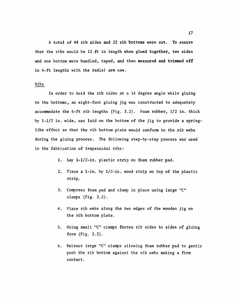
A total of 44 rib sides and 22 rib bottoms were cut To assure
that the ribs would be 12 ft in length when glued together two sides
and one bottom were bundled taped and then measured and trimmed off
in 6-ft lengths with the radial arm saw
Ribs
In order to hold the rib sides at a 14 degree angle while gluing
to the bottoms an eight-foot gluing jig was constructed to adequately
accommodate the 6-ft rib lengths (Fig 32) Foam rubber 12 in thick
by 1-12 in wide was laid on the bottom of the jig to provide a spring-
like effect so that the rib bottom plate would conform to the rib webs
during the gluing process The following step-by-step process was used
in the fabrication of trapezoidal ribs
1 Lay I-l2-in plastic strip on foam rubber pad
2 Place a I-in by l2-in wood strip on top of the plastic
strip
3 Compress foam pad and clamp in place using large C
clamps (Fig 32)
4 Place rib webs along the two edges of the wooden jig on
the rib bottom plate
5 Using small C clamps fasten rib sides to sides of gl~ing
form (Fig 32)
6 Release large C clamps allowing foam rubber pad to gently
push the rib bottom against the rib webs making a firm
contact
18
1 Apply dithloromethane to inside edge of rib using a hyposhy
dermic needle (Fig 33)
8 Wait 30 minutes then release small C c~amps and remove
finished rib from jig
9 Inspect rib for any opening along line and if necessary
reseal with PS-30
Floor Beams
Fabrication of the floor beams consisted of four steps
1 Cutting 8-in by 6-ft strips for web plates
2 Cutting openings in the web plates as shown in Fig 34
to accommodate the continuous ribs
3 Cutting five lIS-in x 2-l2-in by6-ft flange plates
4 Gluing flanges to the web
Some problems were encountered in making the web openings for the
floor beams The sides of the 3-in deep openings were cut with a radial
arm saw while the 1-12 in bottom was cut with a coping saw The same
technique as in gluing the ribs was used to glue the web to the flange
The flange was placed on a foam rubber pad and a series of clamps were
used to form a jig to keep the web upright (Fig 35) Small wedges were
then slipped under the foam pad where needed to provide the proper fit
Gluing was accomplished by applying dichloromethane to both sides of the
web No PS-30 was needed
Assembly of the Orthotropic Deck Model
After the fabrication of all the basic elements of the orthotropic
19
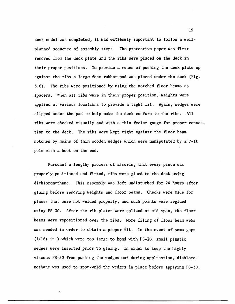
deck model was completed it was extremely important to follow a well shy
planned sequence of assembly steps The protective paper was first
removed from the deck plate and the ribs were placed on the deck in
their proper positions To provide a means of pushing the deck plate up
against the ribs a large foam rubber pad was placed under the deck (Fig
36) The ribs were positioned by using the notched floor beams as
spacers When all ribs were in their proper position weights were
applied at various locations to provide a tight fit Again wedges were
slipped under the pad to help make the deck conform to the ribs All
ribs were checked visually and with a thin feeler gauge for proper connecshy
tion to the deck The ribs were kept tight against the floor beam
notches by means of thin wooden wedges which were manipulated by a 7-ft
pole with a hook on the end
Pursuant a lengthy process of assuring that every piece was
properly positioned and fitted ribs were glued to the deck using
dichloromethane This assembly was left undisturbed for 24 hours after
gluing before removing weights and floor beams Checks were made for
places that were not welded properly and such points were reglued
using PS-30 After the rib plates were spliced at mid span the floor
beams were repositioned over the ribs More filing of floor beam webs
was needed in order to obtain a Eroper fit In the event of some gaps
(116plusmn in) which were too large to bond with PS-30 J small plastic
wedges were inserted prior to gluing In order to keep the highly
viscous PS-30 from pushing the wedges out during application dichloroshy
methane was used to spot-weld the wedges in place before applying PS-30
20
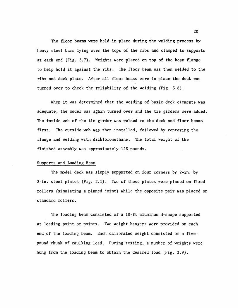
The floor beams were held in place during the welding process by
heavy steel bars lying over the tops of the ribs and clamped to supports
at each end (Fig 37) Weights were placed on top of the beam flange
to help hold it against the ribs The floor beam was then welded to the
ribs and deck plate After all floor beams were in place the deck was
turned over to check the reliability of the welding (Fig 38)
When it was determined that the welding of basic deck elements was
adequate the model was again turned over and the tie girders were added
The inside web of the tie girder was welded to the deck and floor beams
first The outside web was then installed followed by centering the
flange and welding with dichloromethane The total weight of the
finished assembly was approximately 125 pounds
Supports and Loading Beam
The model deck was simply supported on four corners by 2-in by
3-in steel plates (Fig 21) Two of these plates were placed on fixed
rollers (simulating a pinned joint) while the opposite pair was placed on
standard rollers
The loading beam consisted of a 10-ft aluminum H-shape supported
at loading point or points Two weight hangers were provided on each
end of the loading beam Each calibrated weight consisted of a fiveshy
pound chunk of caulking lead During testing a number of weights were
hung from the loading beam to obtain the desired load (Fig 39)
CHAPTER 4
TEST RESULTS
The Computer Model
A discrete element model capable of handing orthotropic plate
problems (18) was used for the analytical part of this investigation
The model (Fig 41) represents the stiffness geometry and support
conditions of an orthotropic plate continuous over flexible floor
beams The -principal features of this method include the representashy
tion of structural members by a physical model of bars an~ springs
which for analysis are grouped into two orthogonal systems of beams
and replacing the differential equations for orthotropic plates by
their finite-difference equivalent The problem then is reduced to
solving a large number of simultaneous equations rather than one complex
differential equation The computer program developed from the above
model permits the stiffness properties of the orthotropic deck and
floor beams to be included on an individual basis -thus resulting in
a more realistic representation of the bridge deck as an equivalent
orthotropic plate The bending stiffness of the plate in the x- and
y-directions and the Poissons ratio effects are represented by elastic
blocks at the nodal points (Fig 42) Support conditions are simushy
lated by elastic springs of appropriate stiffness at each joint while
twisting stiffness is modeled by torsion bars connected to the rigid
bars between elastic nodal blocks
22
Member stiffness and load values are entered in the ~omputer
program by first dividing the slab into increment widths of hand h x y
in the xmiddot and y-directions respectively Figure 43 shows the coordishy
nates of the deck model under investigation A joint is defined as
the intersection of the station lines in each x- and y-direction while
a mesh is understood to be the area surrounded by four jOints Or~hog-
onal flexural stiffnesses D and D are entered on a per unit width x Y
basis The torsional stiffness H is input on a unit width basis for
each mesh its value is determined with the aid of a separate computer
program following the method in reference (2) A listing of this proshy
gram is provided in Appendix ICa) Applied loads are assumed concenshy
trated at each joint therefore a distributed load must be proportioned
among the surrounding joints on a tributary area basis Unyielding
upports are simulated by introducing very stiff springs (500 kin)
at the joints on the support station line Discrete members such
as floor beams and girders can be entered on an individual basis by
giving their total stiffness values A typical computer output is
given in Appendix I(b)
Idealized Sections
The only function of the tie girders was to provide a flexible
support for the floor beams Therefore no attempt was made to properly
scale the tie girders~ as in an actual bridge their span lengths and
cross-sectional dimensions would be much greater ConsequentlYI
theoretical investigations by Chwalla (5) on determining th~ effective
23
width of the deck acting as the top flange of the tie girder could not
be used Instead this effective width was determined experimentally
by measuring girder deflections for several symmetrical loading condishy
tions and computing the required inertia needed to obtain this deflection
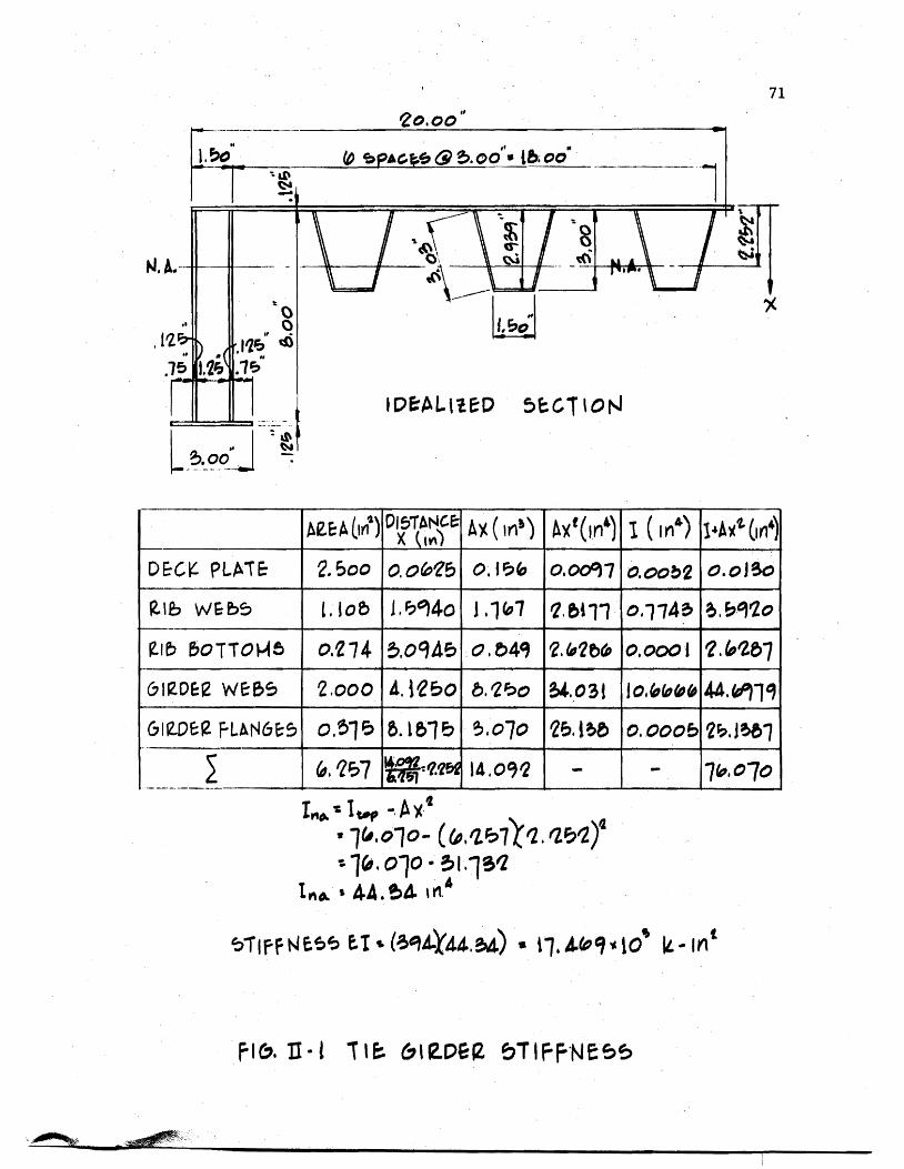
The tie girder inertia value was found to be 4434 in4 which corresshy
ponds to an effective deck width of 20 inches
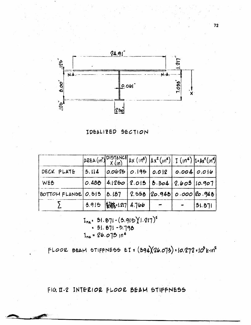
The effective widths of the orthotropic deck plate acting with
a rib and floor beam were computed using the method outlined in the
AISC Design Manual (2) and others (23) It was determined that because
of its narrow width the tie girder would offer little or no rotational
restraint for the floor beams this justified using the full length of
the floor beam as its effective span when computing the effective
width All idealized sections along with corresponding inertia and
stiffness values are shown in Appendix II
Calculated vs Observed Deflections and Strains
(a) Deflections All deflections were corrected to account for
support movements during loading This was done by using a linear
interpolation of the settlements between supports Although a biaxial
stress field exists in the rib plates the use of uniaxial strain
gauges to determine strains at rib bottoms was justified through
experimental observations made by Erzurumlu and Toprac (9) Linearity
checks were made on deflections and strains for all loading conditions
prior to plotting any profiles
computed and measured center floor beam deflections are shown
in Figs 44 through 49 for all loading conditions At this juncture
24
it should be noted that the mathematical model does not account for
shear deformations The deflection due to s~ear was computed for a
lOO-lb load applied at the center of the floor beam and was found to
be 0023 inches If this correction is applied to the computed deflecshy
tions of Fig 44 the correlation between computed and measured
deflections would be very good with the difference reduced to less than
one percent Examination of floor beam deflection curves for other
loading conditions indicates that when the load is not directly over
the floor beam there is closer agreement between computed and measured
values This substantiates the need for a shear deflection correction
on floor bearns as less shear correction would be needed for smaller
floor beam loads It is interesting to note that good agreement exists
between computed and measured deflections at the tie girder as long as
the load is symmetrically located however as Figs 48 and 49 indishy
date a difference of approximately five percent exists when loads are
positioned in the driving lanes Thus the tie girder inertia value
and corresponding effective deck width are dependent among other things
upon the position of the load which is what Chwallas (5) theoretical
investigations indicated
Good agreement exists between experimental and computed deflecshy
tions of the ribs in Section 1-1 (see Fig 211) for the loading condishy
tions shown in Figs 410 through 417 Generally measured deflections
are slightly more than those computed with the difference seldom
exceeding five percent Again shear deflections may account for
25
some of this discrepancy as the difference is usually greater in the
center of the deck or directly under the loading pads Another possishy
ble cause of discrepancy is the localized distortion effect in a rib
produced by the moving together of the deck plate and the bottom rib
flange resultingmiddot in a lowered moment of inertia and section modulus
when a rib is under load In Fig 411 the computed deflection
directly under the load is greater than the measured deflection This
behavior is believed to be caused by the fact that the wheel load is
input as a point load due to the limitation of the mesh size Because
the 6-in long loading pad is centered over a node it cannot theoretishy
cally affect adjoining nodes In actual behavior however the load
is distributed to some extent to the adjoing nodes thus accounting
for the difference between measured and computed deflections on the
adjoining ribs An examination of Fig 417 reveals the same type of
loading condition resulting in the same relationship between computed
and measured deflections The extent of the discrepancy is not great
in this case as the load on each node is only one-half that of Fig
411 Generally when the load is over the floor beam the rib action
is fairly uniform (Figs 410 413 415 and 416) When the load
is in an adjoining panel centered between floor beams (Fig 412)
there is a slight rise in the center rib The decreased magnitude
of the computed deflection again is due to the load being input as a
point load A check of the strains at this point both theoretical
and measured reveals that the bottom fiber of the loaded rib is in
compression In contrast the adjoining rib bottoms are in tension
26
and thus verify the shape of the curve The deflections and strains
for computer coordinate (66) (floor beam bottom) are given in Table I~
Deflections again vary depending on the position of the load with the
greater percentage difference being when the load is near the floor
beam
(b) Strains Overall strains vary anywhere from 1 to 49 percent
with computed values generally higher than measured values The large
discrepancy between computed and measured strains is probably due to
the following causes
1 Instrumentation error
2 Warping of the deck due to uneven support settlements
3 Idealization of the structure as a discrete element
model
4 In the case of ribs the assumption of a uniaxial
stress field in the rib bottoms
The instrumentation error could be as high as ~20 ~inin
and would account for a larger percent difference between computed and
measured values in low ranges Therefore readings less than lOO~inin
would be too small to verify the adequacy of the discrete element comshy
puter pr~gram
The warping effect could also cause plus or minus strain errors
depending o~ the magnitude andlocation of the sUPPQrt s~ttleIlJ~nt$
27
A safe assumption is that the more warping the greater discrepancy
between computed and measured strains As an illustration referring
to Table I the 30 percent difference in loading condition F could
be due to warping because of the unsymmetrical loading in that case
An examination of the support deflections reveals that Gauge No 7
drops 0049 in while the diagonal corner Gauge No 9 drops only 0011
inches This indicates a warping effect and a possible explanation of
the 30 percent discrepancy
While the accuracy of the discrete element model could be
improved by using a finer grid the mesh size chosen was considered
adequate for the purpose of this investigation and prevented excessive
use of computer time Because the theoretical data generated for
deflections and bending moments are average values there will likely
be some differences between experimental and computed values The
errors introduced by assuming a uniaxial stress field in the rib
bottoms would have some influence on the computed versus measured
relationship which would be more apparent when the ribs are heavily
loaded
Computed and measured strains for most loading conditions are
given in Tables II through IX Keeping in mind the previously
mentioned possile sources of error there is generally a good agreeshy
ment bet~een theory and test results It is interesting to note that
when a load is directly over a rib (Tables III and VIII) the computed
strain is considerably greater than measured strain--38 to 49 percent bull ~ ~
28
This can be partly attributed to the load being input as a concentrated
load and partly to the excessive distortions of the rib plate directly
under the load This localized distortion effect was also noted in the
investigation reported in Reference (9) A check of the floor beam
strains near the girder (Table II) Gauge 1-7 indicates there is tension
present at that location Although the strains are too small to be conshy
clusive it indicates the assumption made earlier which stated that
the tie girder offered little or no rotation restraint for the floor
beam was reasonable
It could be concluded that within the limits of the experishy
mental program the orthotropic deck responds as predicted by a discrete
element computer program in the elastic range
1
CHAPTER 5
CONCLUSIONS AND RECOMMENDATIONS
Conclusions
In view of the findings documented in Chapter 4 it may be conclushy
ded that
1 Plastic sheets of acrylic can be used as a modeling material
for the fabrication of orthotropic deck models Ordinary
woodworking tools are effectively used in the deck construcshy
tion thus keeping costs to a minimum
2 Dichloromethane and PS-30 are compatible an~ effectively
simulate welds in steel orthotropic decks when tests are
conducted within the loading range of this investigation
3 Creep effects of plastic do not adversely influence test
results when proper testing procedures are used
4 Indirect models can be constructed from plastic acrylic
material to test structures as complex as orthotropic decks
5 The discrete~element model proposed by Matlock and Panak (18)
is effective in predicting the moments and deflections
along grid lines of multiple panels of orthotropic decks on
flexible supports
30
Recommendations
Future investigations involving orthotropie bridge decks should l
based on this study be concerned with the following
1 A computer program using a finer mesh size should be run
on this model to see if the results would change signifi shy
cantly
2 The deck should be supported on concrete blocks so that
warping would not be a factor in recorded deflections and
strains
3 The box girders should be properly scaled so that a check
on its torsion restraint could be made
4 The model should be extended to a length such that a full
AASHO Highway vehicle could be simulated as a live load
5 Investigations should be conducted on the interaction of
the rib and floor beam by extensively gauging the areas of
intersection
6 Decks using different types of ribs (open biserrated etc)
should be modeled and their response compared with those
obtained from closed rib models
7 Orthotropic decks on flexible supports should be modeled
with steel as a means of checking the ultimate strength of
the system
REFERENCES
1 American Association of State Highway Officials Standard Specifications for Highway Bridges 1965 Washington DC
2 American Insitute of Steel Construction Design Manual for Orthotropic Steel Deck Bridges New York 1963
3 Boussinesq J V Complements ~ une Etude sur la Th~orie de lEquilibre et du Mouvement des Solides Elastique dont Certaines Dimensions Sont Tres Petites par rapporta LAutre Journal de Mathematique Paris 1879
4 Cauchy A L De la Pression dans un System de Points Materiels Exercices de Mathematique Paris 1928
5 Chwalla E Die Formeln zur Berechnung der vollmittragenden Breitediinner Gurt und Rippenplatten Der Stahlbau No 10
1936
6 Cornelius W Die Berechnung der ebener Flachentrag-Werke mit Hilfe der Theorie der orthogonal-anisotropen Platten Der Stahlbau Vol 21 1952
7 Engineering News-Record Californias Orthotropic Bridge Set to Go October 29 1964
8 Engineering News-Record The San Mateo-Hayward Bridge A Fabrishycation Dream June 23 1966
9 Erzurumlu H and 1oprac A A Research on the Deck Elements of the Ammi System Structures Fatigue Research Laboratory Report No P550-12 The University of Texas Austin March 1970
10 Geckeler J W Elastizitatstheorie anisotroper Korper Handbuck der Physik Band VI Berlin 1928
11 Gehring R De Aequationibus Differentialibus Quihus Aequilihrium et Motus Laminae Crystallinae Definitur Berlin 1860
12 Guyon Y Calcul des Ponts Larges ~ Poutres Multiples Solidaris~es par des Entretoises Annales des Ponts et Chaussees No V Septembre-October 1946
13 Hardenherg G J Design of the Superstructure of the Port Mann Bridge1f The Engineering Journal July 1961
14 Hedefine A and Silano L GI Design of the Fremont Bridge ASCE National Structural Engineering Meeting Portland
32
15 Heins C P and Hails R L Behavior of Stiffened Curved Plate Model Journal of the Structural Division Proceedings of the American Society of Civil Engineers Vol 95 No ST-l1 November 1969
16 Huber M T HDie Grundlagen einer rationellen Berechnung der kreuzweise bewehrten Eisenbetonplatten Zeitschrift des Osterreichischen Ingenieur - und Architekten-Vereines Vol 66 No 30 1914
17 Massonnet Ch Methode de Cal cuI des Ponts a Poutres Multiples Tenant Compte de leur Resistance ~ la Torsion Publicashytions International Association for Bridge and Structural Engineering Vol 10 1950
18 Matlock H and Panak J J A Discrete Element Method of Analysis for Orthogonal Slab and Grid Bridge Floor Systems Center for Highway Research Report No 56-25 The University of Texas Austin May 1972
19 Mayer R Die Kurpfalzbrucke uber den Neckar in Mannheimtt Der Stahlbau Nos 6 7 8 1952
20 Naruoka M Okabe T and Hori K An Experimental Study on Model Continuous Beam Bridge with Steel Deck Publications of International Association for Bridge and Structural Engineering Vol 18 1958
21 Pelikan W and Esslinger M Die Stahlfahrbahn-Berechnung and Konstruktion MAN Forschungsheft No7 1957
22 Shields E J Poplar Street Bridge Design and Fabrication Civil Engineering February 1966
23 Troitsky HS Orthotropic Bridges Theory and Design The James F Lincoln Arc Welding Foundation August 1967
24 Troitsky M S and Azad AK Bending and Torsion in Orthoshytropic Deck Box Girder Journal of the Structural Division Proceedings of the American Society of Civil Engineers Vol 98 No ST-9 September 1972
25 Voigt W Lehrbuch der Kristallphysik Leipzig 1910
26 White Richard N Similitude Requirements for Structural Models Conference Preprint No 469 ASCE National Meeting on Structural Engineering Seattle Washington May 1967
-
P
- () ~ -4 X ) -- tQ - 0 -I ftl
rshy ~ r 1gt
-1
C It (
~
~
shyo
Z g
- c o-Z
Ie
CP C
---
-
-n-G ~
0 1tI lt
0
t IfI Z J ()
Z P
I I
I I
I
I I
I i
I
-tshy I I t I ~
I I I I I
~
t ~
I r-shy
1-shy I I I I I I I I I I
I I I I
I I I
-
I
I I I
I I I
I I
Imiddot
-
bull shy0
--tshyI
I po U
Q r---shy 0
I i
~ 0
I
)0
~ omiddot-0 ~ T bull l
l
~LO II
OOlte
middotOOmiddot~middotmiddot---I
GLQ ~olt -rL1
OO~ 00laquo
gt o obull
tf
CNOIN~HIO
0 ~~HM 9middot21middotCJ1~ bullPti Z
JJd 1fO 1nJS 4MJ ~Q dOl H1 14
1 QJO01 d11t19ff
bullIampZ Ie I~ J~fianlt ~11aM flU iD dol 4tU J ~41~ JatlN~
(l~t1n4Ci( -amiddotl1f14 oN1
01 l7Z til
OJ oz z
01 Oll 9
CHWI
L$ C~HN
~ tdl Nt
dVO ~aHM
1g=3HM NaJ t11 -10 4-a~ l 11NO lt middot21middot)~ I
~JJM irtJ ~del erialJ 4211 J ~oJo ~1J
lfLNO ~1(11l1
~=3a1 IN=lfn~J ClJ10 llJltCnlt i3U (1110C odo 11 11lo~
OZltH --ao~ ~~IC d ~NIO~O 1z middot~Id
fa tt a oe 01 ---~l
Z~
01
~Yiq~~ ~a~rAJJlta
~ta ~o J~ ~fd ~
1 ~shy ()
~ 0 Id
lj~t43001~ N~~Ml~Q t+1r+1ML=aca ltofd d
CI 0
H1aq ~OG1-l -10 ~ clta Ia If CO vd ~
1 0
------
N k I
C () n -till J
~-9ca (1001 d) lY bull ltltlIa N~~Mll ltQ~d -
I~ raquo ~
1 ---1-- 0 f 111
)~
c ~aq 2I001-i N~~Ml Haca 7J001d -~Cd ~ C317J 11 ta~d -(f) -io bull ~I2J LV 011d bull
I 1)1 ---shy-PJ----4---+ 0
Q 9
AI
~-lf11 l J
--shy-~---t----- -
j~
0- lIf
--
-~ o
I Imiddot I I I I
I
I I sa I
bull- bull
tEl - - l=~ Abull -C)
bull ~
I II
I I I
I ta I ~ ~~ lar I j Il~ CP e 0
tIbull
~bull ~ -shy
[l ~ 1-1 -T
bull --1 bull bull bull -~ Jl 1 bull -abull ~ I I I I
~I I JQ
Ql I I I I ~ tf of(
Jl ~
tclXll~~4 1IDD~ _ I - r-
if bull(Jill i I
I
I I
I I
II
I
ot
---
-
II
G ~
-
r 0 ~ tgt
0 ~
Z
~
0 tgt r
G 1gt C lti
I I I I
I I
I I I I
I I I
I 1
-- _shy - - I
I I t
t I
I I I
I I I
1 I
o~ P~ t (~ lt1gt1= c~ bull bull Q )l ~ ~ -
i I
I shy
I I I I I
bull bull oa I
~
1Q I I I i 0 I I I I I - I-4
~
I
~amp~faq 2Joo -I -shy -I r J --1-shy I I I
I I I II
I
_L
ED CD agt
)02z[
lQ ()-C0 ~UQ
)
0 ~ It )10 U
-1-
U t J
t -0 0
42
Fig 212 Test Set-Up During Testing
Fig 213 Bridge Used in Deflection Measurements
43
Fig 3 1 Radial Arm Saw Used fo r Cutting Plastic Sheets
Fig 3 2 Gluing Jig and Clamps
44
I
Fig 33 Application of Dichloromethane to Rib Seams
Fig 34 Cutting Openings in Web Plates
45
Fig 35 Jig Used in Gluing Floor Beam Web to Flange
bull Fig 36 Deck Assembly Prior to Gluing
46
Fig 37 Ass emb ly Us ed to Hol d Floor Beam In Place Prior to Gl uing
Fig 38 Turning the Deck Over
( gJ ) 1=3COH JN~r~1-=3 1~-iZJca HOCl-i LNIOr 11dkl z-v middot91j
( qy) ~L~1d I d0211oHJ2IO -10 1aOH LN3H31~ JJ~ZJC(j -tJl-i
x~~~____________~
2
-r
middotat
x 2~ 1 01 ( ~a ~ C lt~ ~I 0 --u
-~ ~
~~ ~ f) middot)(4
D b-
~o
~4 t IU
1)1 G
J
-n I~flt)(~L1J) middotPN ~9H-(i ~
~ I -1 rT nn rrrr1 TTlVf- d)
bull ~ d~Or lID IIU IIJJ LUJ
)Y 0 (01 q ~V C1JC101
0
() shya r --hTIm I 1111 I~
l~ ~ I1II
D -0 -aN 00~O1 ~ tJ4 o~a ~o - c - -I P
ct 10 -~ lti -shy IQ
1
-) ----- _bull -tt -shy-t
-(p
0
~ 0
I)
-~ ~
~ P
~ ~ 61
0
~
~ ampgt p ~ tt Z 4 m ft
r () 0 F
0 ~ 1gt - ~
w r n ( -4-~ 7shy
r 0 Cgt 0bull ~ ()
7 C 0
bull () G to a
C -I Il 0
0
0 tI
r
0-
0 0-
- Q 0 I
0 I ~
0 0 00
I Z z ( r tT ~ lti
~ ~
- 0
( -l -I t -a 7 ( -4
11 r l1
r ()
~C ~---- ~ ~ shy ~ - 0 8~ ~ tIshy -
bullbull 0 1 0 0 lt) 0 r 1t ~ r (
t - -()
L
) P P ~ C)
Z P Jgto
0
p
~ 1 Qshy
~ s
l Z -4 n f)
r l 0 1
G ro P 1_ Q t( l r ttl ( -- ) Z
r (l 1gt
~ ( () Z 0 Q
() 0 0
()
i I
-
~~ -1)
-~
-~
~~ -
-~ ~
-a
-() II
()
U ~
-~ f(0 1gtshyt(J ~~ e w ~o 0
() C)
~ () -()
i I
9 ~
~
~ t1 L --I rt ll
r -
C) 0 1
~ w I_ 0 t
r w (
-- - -Q
Z
r ~ 1gt Q ~ 7 ~
~
1 r IT (
--
o~ I -z ( I It
~
~
~
~ -~
() shy
~ N l 0 () ~ U
LS
G - ~ 1
rshy)
~
$ 1gt
r shyo l -r r f(1
--l )
7
-
0 It 1 r It t - 0 ~ ~
-Z 0
~ I 0 O~ z I (
~ -~ ---] m ~
N ~
ii ~ 0 -ltP shy ()
IT 1 ~
t
)
~
~ -~
lt)
I
shy Gmiddot ~
-
r (J
It
Qrshy-~ t) l ~ ll () () 1
W bulli
rQ
1gtshyi
w~ r ft ( -t - 0 7shy
r ) 1gt ~ middot ) ~ Z
middot ~
n
- 9
-~ -J IT ~ --shy0 Z II-shy
~ n r
-4 )
z N Ol - fl 0
rshy r ~ Igt 0 ~ Z ~ l
~ Sl-() 0
~~ Ot i i
I shy~ a (l
~ 1)( c~ ((
wo u
0 fT shy
t) t) IT 0
~ 8~ 0 -l
(5 I ----I I Z C Z ( I (T
~ ~ ~ 0 ~
I J~ t1 (( --lshyshy( () 1gtshyZ ~ bull
U It
rshy bulltI shy-II =Jesshy ( --
l -I 0 z 8shy 0shy
fl ~
l (
0
rshy(l
r t) 1gt ~ bull ~
z ~
~ Jgtoo
~
~ o I
~ ~
-)l J
~ ~ 0 z
-I
0 tr -p r 11
n Q Z ~shy P ~ ta 0 1- r - r ~ 1gt ~ ( Q1 ~
(~ 0
t -0 C 0
0 fJ
rshy rn (
-~ ~ ~ -I 0 o 0 0 o bull ~ 8~ I I bull i I Z
--
1--shyZ ( I
-~ en ~ ~ ~
1 ~ -J ( -
0 z --
~C-~~O - f1I -~TI ~r
0II (
--- 0 ~ 0 ~l~ Z 0 1
1Q
Ibull
-~~~ I -~~ _1G -() 0
~o S
rshy f1
r C) 1gt 0 ( 0 Z -0
0
--s U C ~ 11 0
9
-l ( ~
-4shyt) z bull
- 0 n
rshy (t1
--l t) Z lQ
-0 -a fQ () r
r 0 ~
~ ( () Z ~
sgt
0 IT -n r IT ( -l
0 Z Z ( -t ff J
6 -I bull ~ S
N
0 0 ii ~
S) p ~ ~ ~ -0 0 6
8 o ~ 0 i I i I
~ ~ -~ U ft C
shy0 z -- - - Cl1
- r~ - lr-
-~ ( 11 0 1gt
to ) -0 C C f3 -t t Cl1 ~ 0
t~ shy 0 ()0 z
r
r ) 1gt ~ f ~ 7shy9 0
~ -J
t
(p ~
0
C
() 0 ~ 08~ o~
i
~ ~ -J shyl 11 ( -t 0 Z bull-~ rshy Il t ~ --- --I-~
() 7shy
N tl 0 P
Q lQ ~ ~ lt)
r ~
r Il (1 WI
r r 0 0 1gt tgt 0 ~ ( ( tgt a Z z 0 0
t ttl
I ~
1 (
o I
~ c ~ 1Q
ltV 0 Q
- ltY-o o 0 I
C
TABL
E I
FLOO
R BE
AM D
EFLE
CTIO
NS
FOR
GAUG
E LO
CATI
ON
1-5
FL
OOR
BEAM
STR
AIN
RE
ADIN
GS
FOR
GAUG
E LO
CATI
ON
1-9
LOAD
iNG
CON
DIT
ION
r
A
B
C
D
E
F
-
Com
po
Mea
s
Com
po
Mea
s
Com
po
Mea
s
Com
po
Mea
s
Com
po
Mea
s
Com
po
Mea
s
Def
lect
ion
(1
-5)
Inch
es
011
4 0
124
013
5 0
151
011
3 0
124
013
2 0
145
011
0 0
116
013
0 o
~42
Com
pute
d M
easu
red
091
0
89
0
91
091
0
95
09
2
iStr
ain
(I
-9)
Mic
roin
ches
17
5 20
6 61
8 53
1 15
7 17
3 44
6 38
0 12
2 13
7 33
8 26
0
Com
pute
d M
easu
red
-shy~-
085
1
16
----_
__
_
__
shy_
_shy
087
1
17
-_
shy
089
ff
13
0
P =
100
LBS
til
--
J
58
TABLE II
STRAIN READINGS FOR LOADING CONDITION A (1
I
~ (1)
cQ
~ 0 0
~
~ (1) +-gts (1) u
GAUGE NUMBER Computed u in in
Measured AI in in
ComEuted Measured
I-I 873 789 111
1-2 679 660 103
1-3 510 495 103
1-4 361 329 110
1-5 229 202 1 13
1-6 - 1-7 -
-- en
Jl 0 - bull
s 0 +-gt u (1)
til
11 3 205 208 099
11-6 202 229 088
11-8 194 199 097
11-9 183 173
-106
11-10 170 147 116
- -g g instruments
P 100 LBS
ji
I
59
TABLE III
STRAIN READINGS LOADING CONDITION B lt
~ (J)
Ql
~ 0 0 ~
~ (J) ~
53 u
Computed Measured Computed GAUGE NUMBER u inin JIJ inin Measured
I-I 599 599 107
~
1-2 486 495 098
shy
1-3 375 379 099
1-4 272 251 108
1-5 176 156 113
1-6 -
1-7 -
r- en
0
r-I ~ -
I
sect r-I ~ U (J)
U)
-11-3 2429 1635 148
11-6 453 593 076
11-8 238 242 098
11-9 202 174 116
11-10 -
Too small and within the range of tolerance of record1ng instruments
Wheel directly over rib P = 100 LBS
60
TABLE IV
STRAIN READINGS FOR LOADING CONDITION C 11
Computed Measured ComEuted GAUGE NUMBER ~ in in AJ inin Measured
I-I 587 500 117
1-2 601 559 108 I
i
I
~ 4)
CQ
ft 0 0 -c u ft G) +J
5 u I
I I
1-3 531 507 105
1-4 377 326 116
1-5 241 190 127
1-6 -
1-7 -
tI)
c c oi
-c
-c
s 0 +J 0 G)
U)
11-3 198 160 122
11-6 196 184 107
11-8 190 154 123
middot11-9 180 133 135
11-10 -------- shy -
Too small and- within the range of tolerance of record~ng instruments
P = 100 LBS
jl
~11~~---~middot
61
TABLE V
STRAIN READINGS LOADING CONDITION D 11
Computed Measured Computed GAUGE NUMBER u inin M inin Measured
I-I 424 397 107
1-2 427 439 097
a (J)
i
~ 1-3 378 389 097 ft 0 0
u 1-4 275 271 101 ft Q) +oJ s (J) 1-5 178 160 111u
1-6 shy
1-7 shy
11-3 341 293 116
~ 11-6 844 760 111 en c -t et J
II~8 832 731 114 t
s 0 11-9 260 220 118
-If +oJ
-0 Q)
CI)
11-10 192 159 121
Too small and within the range of tolerance of record1ng instruments
P = 100 LBS
c
62 ~ bullbullbull ~ - ~~ ~ ~ W bull
TABLE VI
STRAIN READINGS LOADING CONDITION E
Q)
eQ
Jot 0 0 u Jot Q) +Js Q) u
Computed Measured Co~uted GAUGE NUMBER ~ in lin AJ in lin Measured
I-I 435 395 110
1-2 558 514 109
1-3 495 478 104
1middot4 451 431 105
4241-5 380 112
1-6 206 165 125
1-7 -
(I)
c~ cx gti
I
6 ~
+J (J Q)
Cf)
11-3 185 152 122
11 6 196 181 108 bull
11-8 205 175 117
11-9 209 158 132
11 10 - Too small and wi thin the range or to1erance-of recorc1Jng
instruments P = 100 LBS bull
bull
63
TABLE VII
STRAIN READINGS LOADING CONDITION E1 2
Computed Measured C0RPuted GAUGE NUMBER u in I in M inin Measured
I-I 435 380 114
1 2 331 294 113
1-3 243 195 125
~ 1 4 169 138 122ltD co $-I 0 0 1-5 shy u $-I ltD +l 1-6 shy= ltD
u
1-7 shy
11-3 1
185 137 135
11-6 170 152 112 en
0 5 11-8 153 135 113 bull r 11-9 135 112 1200
- +l -0 ltD
Cf) 11-10 shy Too small and within the range of~ tolerance ofrecording
instruments P = 100 LBS
I
64 ooo _~~ _ bull
TABLE VIII
STRAIN READINGS LOADING CONDITION F
Computed Measured COIDEuted GAUGE NUMBER ~ inin~ ILl in lin Measured
I-I 317 265 120
1-2 388 346 112
1-3 349 331 105~ CD
bull cl
~ 0 0 1-4 313 292 107
14 ~
~ CD 1-5 282 243 116sCD u
1-6 shy
1-7 shy
11-3 309 357 087
~ 11-6 1343 975 138en I 0
c J
14 11-8 337 412 082 I
14
r 0 11-9 339 382 089 0 CD
CI)
11-10 1349 907 149
Too small and within the range of to1erance-or-recora1ng instruments
Load directly over rib P = 100 LBS
65
TABLE IX
STRAIN READINGS LOADING CONDITION F1
-Computed Measured Co~uted
GAUGE NUMBER ~ in lin AI in lin Measured
I-I 317 253 125
1-2 250 206 middot121
~ 1-3 191 146 131 (I)
al
ft 0 0 1-4 shy 11
tI
ft (I) 1-5 shys (I)
u
1-6 shy1-7 shy
11-3 309 331 093
U)
c II-6 197 180 109OM rt - 11
t 11-8 169 140 12111
s 0
OM 11-9 147 112 131CJ (I)
tI)
11-10 shy Too small and within the range of tolerance- of recordLng
instruments P = 100 LBS
- ~~ - - -~~ bullbull gt~~bullbull - ~
SDNI1SI1 ~DO~d ~31ndWOJ
I XION3ddV
67 ~ ~ ~ bull ~ ~ _~ a bull- ~
I(a) PROGRAM USED TO DETERMINE THE TORSIONAL RIGIDITY
JIDI 8-DIP11I O A IlIBCDO 1101
I I RIM THIS PROGRAII FIOS THE TOaSIGIIAL RlalDITY POil ORTlIOllIOmiddot I 11M PIC DICKS WITH fRAPIZOIDIL RSBS 3 RD II-THleDUS 0 tHE DICJCPLAtS I 6
IUQIJ TbullbullTHJCKIIUS O~ THB alB PLATa RDI A-WIDTH 0 TId IlIB ca) Rill la-SPACIIII or TRS RIBS (I
1aUDa DECK bull aIR H8-LH or 0N8 SIDI OF A RIB e-WIItTII 0 tal BASS or tHamp 81B 10 8M s-NODULUS 0 ILAITICITY I O-GDULUS O RIGIDifY S-ACTUAL SPACteO FLOOR 8EAMS 15 READ tlT8AIalWI_bullbull8aGS 80 u-eeHe+ 30 AlaquoAl8~H 0 K-CbullbullA-CtU(AItlbullbull pbullbull- 44 PRIWT -tHE tORSIONAL STII II CK-I--IP so 1CTImiddot3186e 1(Te~fl)middot3YO 10 LI(middotAI+8-CA1bullbulliB~I-CRImiddotAI~3CSImiddot8))OLI--H-CA-+AI--bullbull-aRI-AI-3 100 LLI~~CAI8Le)
10110 c(~a(AI) ce(~e(AJ-~AI)middotlaquo bullbullbullBI)CAIbullbullraquo)C8lC8A)
130 V-middotJtZImiddotfAI-C CAI+CI -(1~16I1-8 Vbullbull(ampI~A)middot3C(EImiddot(AIBLmiddot1150 V3eCLmiddotftlCAI)middota(IRI(H~A-CCI-bullbullCICbullbullCmiddotala160 v-vcveV3) 171 V-V I PRIIIT -Ha TORSI8IIAL RIIUCfIOactoR ISmiddotJV 110 HbullbullbullSC(Vbullbullbullbull)CA+Bl)) S PRIMT-IKE fOBSIOaAL RIGIDITY IS ca-I-I-bullbull 300 DAtA 115bullbull0e3bullbull 3bullbull 3bullbull 30311~19336bull bullbull9 DID
READY ItUN
AX SOPDI 33 fHa TORSIOIIAL ItJr-as II (Kmiddot middot) 19711 THZ TORSIONAL RIDUctlOM ActOR IS O1681~2 THE TORSIaAL RIGIDITY IS (XmiddotI-8IN 151906
il
68
I
Ieb) PROGRAM USED TO COMPUTE DEFLECTIONS AND MOMENTS
~R08 I LOAI) cobullbulllfttr- middot-middotnNE jHit(-lilrTifCNTEIt 0 OIctC Loio- bullbullbull lei
rAil I COttTrtOL DATA- - ---------------
__--y flkl NBIIt-_ -__ bull 3 I-
HOLO RO IRCpoundDtfC PR08 CI-HLt -0 bull - i ~I - HUtt CIRDS-UIJUT TftllltOI[[- I J ~ 4 __t bull
- rI8[ 2~ CGHSTDTrshy
NUM8pound1t 0 tNtItpoundENfS tN x middotDtrtpoundCTlormiddot middotxmiddotmiddotmiddotmiddot middotmiddotmiddotmiddotmiddotmiddot middotmiddotmiddot_middotmiddot middotmiddot-middot middotmiddotmiddot_middot-- middotmiddot -middot-middot--middotmiddotmiddot-----2 ----- middotmiddot-NUits-or-YNcRfMENfs IN dIRECTION My z
INCREMpoundNTLNGTH INX OmiddotIItfImiddot ttx - -- -- -middot-- -i-~middotjmiddotiabullbullbull shyINCItpoundIitNT LENGtH IN ot_poundCTtONmiddotH middotmiddotmiddot middotmiddotmiddot-middot middotmiddot-middotmiddot-middot- -middotmiddotmiddot-~ middotbullbullImiddot+middot
- ---- pbISS-ONS___lTro--- - I SLI8 TICtCNESS cfmiddotaimiddotmiddotmiddotmiddotiiilwmiddotptCljA[-M(hpoundN-fmiddottSmiddotCofllPUfeifmiddot----middot---------
--I spte lIEfJ ti_ tmiddot ncrIL STHSS _ -_-- __ _-_shy
rilL J JOINTmiddotSTIFFNESSINOlOIOmiddotDIT shy
- - - - ---_ JlY -middot middotmiddotmiddot-u_middot -_middot -- ----T----shytn OXmiddot TltU JOINT JOTNT
emiddotmiddotmiddot bull 1 2 middotmiddotmiddotT~-middotmiddot-rlr-Df-- ffJS-C 0middotmiddot-middot-middotmiddot---middot- --middot1---------middot --1middot------ -- -1 o 0bull middotmiddotImiddotmiddotIIJlr-IC-4poundr -1-~ --- ---- -0)---- - -- -- -_---- -----shy
D 24 II 24 -11ltl2 -496tGI -I -0 -I -Ibull __d -6-11middot-- 1 ----------- -----middotmiddotmiddotbullbullZ1--D----- -I ---------- shyJ -12-1 -middot-12-middotD~-middot----middotmiddotr----middot-middotmiddotmiddot---middotr-G7middotI-middot-I _ ---___-_ D II 12 II -1 -a 12fpound+G -0 -0 -0 111 r ---- bull-- --middotmiddot-middot-middot--middot-----lI7R middotT-middot--middotmiddot ----------bull(-- shy1 2~ rr-middot2~ middot-0-----middot--------middot--middot --middotmiddotmiddot-middot middot171poundbullbull[1middot-middotmiddot __middotmiddotmiddotmiddotmiddotmiddot -----bullbull------ --------shybull D I 2 -0 -D -a lffEf -I -I
-TI--TmiddotII-y-l~-middot----T-middot--middot --------------r7~bull - ---- ------ shy_ -- --- ---1 -I ------- --- - ---------T-n-shy
12 bull 12 1 -I -D -I -I -0 bullbull11112middot-ii-middot-z -0 _o-r bullbullbull bull~- ~ jbullbull bullbullbull
middotmiddot-ftmiddot middotmiddottt11 2O~ middot-a 0 ~ 0 -0--- - - - 112 _ - ----_ -__ - ----- --~- -- - -- _---- --~ -shy
fllEmiddot ~ middot JOIN SfI rsSAND LO AO 0 If- CONTlfmiddot-middot-middot-middot-----middot- middot ------------_____
--Iof middot_ltu middot Itbull it ~=~~t~~= ~~ ~ --J(-JOINT JOfNf
0 pound
-rAIL-middot----S1fSrl1NISStJIfImiddot--middot
middotmiddotlto -- TRU MESH -~poundSf
___J___ JI~_~]~ 2~_~ 19pound+IIJ
- raIL middot6~-middotlfjitmiddotmiddotSTlNpoundSS J ATA --~- - -- ---~ -- - ----shy
FROM fARO ---IAft BAitmiddot
n
---__----shy fI1 JSIY
--
__ __
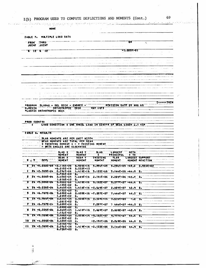
69 l(b) PROGRAM USED TO COMPUTE DEFLECTIONS AND MOMENTS (Cont)
NONE
---------------------------------- shyraBLE 7 MULTIPLE LoaD OaTamp
FRO- lTIfRO--------- ---- ---- ----------- ----- shy Gil ~
JOt T JOINT
--- r-middotmiddot-f--------- -Iooa-II
_ --_ -- ----------~-----
---- ------------- --_------ _ _ ------------~----- ------_----shy
---1
ItOltaM SLag middotOpoundLDCI( -- -[NaUS - middot-middot--------middotmiddot-ltrfSlOijmiddotflffmiddot-O~middot-(jmiddot-69----IfaXIN~- -PTAOTlopIC OECI( iiiI 1973
LiSTie ORTHOTROPIC OEC( --------- -- -------- ~ -
I ------ ~- ----------shy
IItOB (COT ---j--- 0-=-IO=--C-ON=D=I=T=~~middotN---a=-_-9Neuro=_==HEJ _~o~D J_~_Jl~rIt~_F_)~c~ _l_~~()_u_J_M_ ___________
-------- --- _-__------------------------------__--_-------------shy-rAlIlE a USOCl
Staa MOMENTS aRE PElt UNtTMIlTH--middot------------------------------- shymiddot--~ara opoundNfS-i-RE TOTAL P~~ REa
X TWISTING MOMENT bull - TWISTING M(tEltT--middotmiddot----------middot---------------middot----- shy~- 8a aNGLES aRE COCICWYSEmiddotmiddot -~-
SLa x SLas - - --~-~- S( A-B ---(I~GESf- -- 9pound--- ~----------MOM- 0--middotmiddot- x ------ftttINctal xTO--shy8EA x 8poundIM Y TWISTING ~lA8 lARGEST s~
DrIP -- -OMENT-- MOpound --OMtff -OpoundT- - - OENT RpoundampCftON--------shy--~ - -~ ----- ------ - -- ------ shy-~--yen------~ -~-
bull -DIOE-I -211amppound-20 1Damppound-16 1214pound-0 124-O -40 ZSadE-aZ --- _ -6215E-15 3232pound-13 -- ----~ ---------- -------- shyr r~---2S65E-O middot 229I1E-0amp I ampE-13- _middot pound-06- - 9--middot------ shy
1~6~ D I - 2- -~ a06E- 358E-O GE-16 ~r9IE-6-2~209~6 - ~
- - - 10 UE-G 2 j middot3pound-1 1466E-OII 13SE-02 ft- middotr~--6 Z26E-0 3gE-O amp
1133E-2 -- I --Z-6-67E- -695E08
- -- fO SSpoundmiddot2 z4 -59~- 36 bullbullE-08--- - --- --- - - ---1061 pound-a 2
-------- -6167pound-1---1695pound-08 1085E-D2
- 2tt -6Z26pound-I - 3 ca-olt ~~ ------ ~ --1I31E-02 -516pound-1 ~5amp~~-UI - - -- -- 11 3fE -02
11- z~middot- D6E-t_-- 3S8E-D
a - - - 14IE-6 IS2E-d 937t~-07 -ijij O O~ - ~--- --- -- -- - ------ ---------- shyI E-16-2~ 6a9E-D7-2IIr~pound-7-2 9- I o Zbullbull35pound-16-71S1E-01 7 -01 -3-- crshyD----middot----------- shy2835E-16 3334E-14 361-18 -G ma ----- -- -shyO - 72~-a7( pound-07 --~ 3---0------- shy
_d bull 118-16 6041-07 2104E-a--29-~----o - - -~--------------
2815pound-1 -9112~-Ol 9JfIE-01 i44 d bull O ---------- ----------------- shy~ __bullbull-Cbullbull ~-ua ccipound-6 ~ I
IDI6E-D2 a n ---Z-216Jpound--4- 229iiE-~a I f~-16-3133Ea6 --- pound---- --r-bullbull
-----~------ ----726pound-03 - It ----- --- --------------------- ------ ---------- shy
ii
1300N dO S3Il~3dO~d SS3NddI1S
II XION3ddV
71
lt
12000 --middot--middot-- l~ fb ~PAcJ6 (j ~00 lb 00_
~~
~ FhshyN 1-- II II
~()
0 lIZ 12amp di
1fJ J 2 1r
IDfAlleO 5fCTON
L_~middot_90J ~
Aeamp ALItI) DI5TANGfXIV) A)((t) A)(f(n4) ( InA) 1A~L (In)
DE-C~ PLA1Eshy 2500 Oo~Z5 0 I~ OrxPJ7 Ooob2 ooJ~o
~f WampfS L lob 1F~40 J1(01 1 amp111 0middot174amp ~ eq2o 1---shy
~I[ ampoTTO~5 0274 ~oqAamp ob4CJ Z (1edJ 00001 2 middotftJZt7 c II2DEe W~ J Zooo 4 i~ampo b 2gt0 ~03t fOIft1f1~ 44middot11 (1l2D~rz PLAN6~S Of~lamp tgt t610 ~o7o 2amp t~tJ 00000 Z~middotJ~1
~ 7 Mz~ 14fO~12 - - 711070 -----~
I 1~ A~l middotl~ol0- (~tllr7(1 f)1)fJ 1-010 bull ~11J1
1 44 ~4 ft ~ilffNt~~ pound (~~LX44~) bull flAfeJ10middot It_tnt
fie nmiddot 11 E ~ 2DE fl ~T I r roN eeurogtgt
-~gt
U I ~L0 middot~~ s Ou1 qbLmiddot~-IL3middotlcemiddot
amp( LJlJ rA~1 e) fLea degfe WIYl
ILQ1~
Q1b o~
--shy0000
-QtbO~
tJO)L 9ltlt lJ
LJ~middotImiddotc)fL~
L91I
t J I~
ltJ~middotO
1 _shy~---
dJN1 d Holl
LOb or
I)J 00
(tLAI ) J~V+1
0t1J ll
1deg00
(U) 1
1O~q
of 00
(LA I) x ~
CJOb
c( r 0
(tU1) x~
ocgzft
tilJ())OmiddotO
LU) X NV1Cta
ltd9t7O -------
Cd~ -shy
V11c =3 111 dtJ3a
~u) V3~t4 - _-shy
r1 J~OO
--~-- ------------tl-shy---- f~1I t ~ L----------r-~---_J )ampItZ
73
J2A~H
l to
l d
-N ~
)(
10 E~L ED CbtC 1IoN
~ Ieampoj
lI~Lrb=====~ 111 I~
-g lIO
111 2s
1
DI~ANCf A2Eb(lrl1) 1 (t~4-)A~(rf) A~1 (In4) l+Ax(ln 40)X(m)
oo~13ooCo2amp 000(01 OOO~ODpoundG~ PLATr 1 ~amp fP o006f
w~e A 1Zampo4je~O amp~~siooo 2 2 ~AtqiloV~
Z S~6S 00004 20~4e8eoQ4b4F-LAN 6IE OSi~ b ifgt7
L 4~So~2 bCOfgt wmiddot7Egti -~ampe~4 -
10 ~ 4 ~ou (2 6~OX2 S~4J2 4~ ~o(o - 1 027
1 Z1 Z b 4
Flooe erA~ ~1ffNtegt~ cl - (~14-K27Zfraquo= o14e~o~ ~_Inf
rG n- ~ ampXTf rLi 02 F-ooe ~E-A ~ ~1 prN~SS bull
I
LAI JILoo 0 UI-~ ~ shy
Cib~f~ ~i~~ ~ (J-~I Xc ~ t
--UL b L ~ A J1) Imiddot~ lti lt1 l)Itt Q
Jtn -1 ~1 t~ (Ov IA~b~) 1~ ~~~N-I~ ult=
1 ) I 011 - elLA 1 -VLt1)O -1Loz amp
~(llteLoX~ca z f ) -tLo b OUt
tLO(j --~bo ftCl-hcSZ J ~ bebl ~ PJrLQo 00000 ~JLcao ot9Zo ~bo~ bOo Yi 0 LLod ctllZ)
ctQbif fq~z0 VdegVbO qbgso ltbta middot I b~ce 0 I
lt 93 A I ~l-a
11000 01000 rca-ooo ~btoo cvqoo bbLo ~Jv1d ~1~a
(UI) Jx~tI (UI) 1 (t-II ) 11)(~ (itAJ) X1 (tAl) X
~NVJla (zut) V=Jatl I
x
b~middot~ I J l

AN ABSTRACT OF THE THESIS OF Harry Morris Rexin for the Master of
Science in Applied Science presented July 27 1973
Title Response of Orthotropic Bridge Decks to Highway
Load ings
APPROVED BY MEMBERS OF THE THESIS COMMITTEE
This thesis documents the fabrication testing techniques and
response of a plastic scale model of an orthotropic bridge deck To
economically investigate a two-lane steel brfdge deck plastic AcrylicR
was used as a model ing material_ Welds were sImulated with dichloroshy
methane a capillary action sorvent and PS-30 a pDlymerizable
cement Deflections were measured with laboratory dial guages while
strains were monitored with strain guages mounted on the deck
The response of the deck to AASHO vehicle axle loads was comshy
pared with a discrete element computer program used to analyze
orthotropic bridge decks continuous over flexible supports Results
indicate good correlation between measured and computed values for
deflection and strains
j
RESPONSE OF ORTHOTROPIC BRIDGE DECKS
TO HIGHWAY LOADINGS
by
HARRY MORRIS REXIN
A thesis submitted in partial fulfillment of the requirements for the degree of
MASTER OF SCIENCE
in
APPLIED SCIENCE
Portland State University
July 1973
TO THE OFFICE OF GRADUATE STUDIES AND RESEARCH
The members of the Committee approve the thesis of
Harry Morris Rexin presented July 27 1973
APPROVED
Nan-Teh Department of Science
Davi
Ju I Y 27 1973
31 1M AVgtJ 01
ACKNOWLEDGMENTS
Without the cooperation guidance and patience of the entire
Applied Science faculty and staff the completion of this thesis would
have been impossible lowe particular thanks to Dr Nan-Teh Hsu for
his efforts to make it economically possible for me to continue my
education Special gratitude is also expressed to Dr Hacik Erzurumlu
my supervising professor for suggesting the topic of this investigashy
tion and for the constructive criticism and encouragement he provided
throughout the project lowe Dr Franz N Rad thanks for the time
he took to discuss and suggest laboratory techniques during the length
of this project Thanks are extended to Dr Selmo Tauber for introshy
ducing me to differential equations To M Johnson and the Bonneville
Power Administration I wish to express my grateful appreciation for
their assistance with the computer program
Portland State University Harry Morris Rexin Portland Oregon July 1973
- - - - - - TABLE -OF CONTENTS -- - shy
ACKNOWLEDGMENTS
PAGE
iv ~
NOMENCLATURE vii
LIST OF TABLES ix
LIST OF FIGURES x
CHAPTER
I INTRODUCTION
Definitions 1
II EXPERIMENTAL PROGRAM
III FABRICATION
Historical Development 1
Purpose of Investigation 5
Material 7
Equations of Similitude 7
Loading 10
Strain and Deflection Gauges 11
Testing Procedure 12
Splices bull 14
Gluing Techniques 15
Cutting 16
Ribs 17
Floor Beams 18
Assembly of the Orthotropic Deck Model 18
Supports and Lo~ding Beam bull bull 20
~
vi
CHAPTER PAGE
IV TEST RESULTS
The Computer Model 21
Idealized Sections 22
Calculated Versus Observed Deflections and Strains 23
(a) Deflections 23
(b) Strains 26
V CONCLUSIONS AND RECOMMENDATIONS
Conclusions 29
Recommendations 30
REFERENCES 31
FIGURES 33
TABLES 57
APPENDIX Ia 66
APPENDIX Ib 68
APPENDIX II 70
VITA 75
A m
A P
D x
D Y
E m
E P
H
hx
h y
L m
L P
P (xy)
P P
P m
Sf
Sp
w
Um
6 p
NOMENCLATURE
= Area of model
= Area of prototype
= Flexural rigidity of orthotropic plate per unit width in the x-direction
= Flexural rigidity of orthotropic plate per unit width in the y-direction
= Modulus of elasticity for model material
= Modulus of elasticity for prototype material
= Effective or reduced torsional rigidity of orthotropic plate per unit width
= Increment length in the x-direction in the discrete element model
= Increment length in the y-direction in the discrete element model
= Model lengths
= Prototype lengths
= Magnitude of distributed load
= Load on prototype
= Load on model
= Strain scale factor
= Load scale factor
on plate at location (xy)
= Vertical displacement of orthotropic plate
= Model deflections
= Prototype deflections
viii
=Strains in modelEm
=Strains in prototypepoundp =Length of small fiber on the tensile side of a beam
section
5 =Model stresses m
= Prototype stressesESp
~~ bull --~ - ~ ~~~
LIST OF TABLES
PAGETABLE ~
I Floor Beam Deflections for Gauge Location 1-5
and Strain Readings for Gauge Location 1-9 57
II Strain Readings for Loading Condition A 58
III Strain Readings for Loading Condition B middot 59
middotIV Strain Readings for Loading Condition C 60
V Strain Readings for Loading Condition D bull 61middot VI Strain Readings for Loading Condition E 62middot middot
VII Strain Readings for Loading Condition El middot middot 63
VIII Strain Readings for Loading Condition F middot 64middot middot IX Strain Readings for Loading Condition Fl middot middot 65
illmiddot
JI~T QF _fJG1J~~~
FIGURE
11 Orthotropic Steel Plate Deck with Closed Ribs
21 Deck Dimensions
22 Longitudinal Rib and Floor Beam
23 Box Girder
24 Loading Pad Size for HS20 Vehicle
2S Contact Area of 11-14-Ton Wheel
26 Wheel Load Dimensions
27 Contact Area for Wheels Directly on Deck
28 Loading Pad and Beam
29 Loading Conditions and Pad Locations
210 Location of Strain Gauges
211 Location of Dial Gauges
212 Test Set-Up During Testing
213 Bridge Used in Deflection Measurements
31 Radial Arm Saw Used for Cutting Plastic Sheets
32 Gluing Jig and Clamps
33 Application of Dichloromethane to Rib Seams
34 Cutting Openings in Web Plates
3S Jig Used in Gluing Floor Beam Web to Flange
36 Deck Assembly Prior to Gluing
37 Assembly Used to Hold Floor Beam in Place
Prior to Gluing
38 Turning the Deck Over 39 Applying Loading Increments
PAGE
33 ~J
34
3S
36
37
37
37
37
38
39
40
41
42
42
43
43
44
44
4S
4S
46
46
47
~~
xi
FIGURE PAGE
41 Discrete Element Model of Orthotropic Plate 48
42 Typical Joint From Discrete Element Model 48 middot middot middot 43 Computer Grid 49 middot middot middot middot middot middot middot middot middot middot middot middot middot middot middot middot 44 Center Floor Beam Deflection Loading Condition A 50
45 Center Floor Beam Deflection Loading Condition B 50
46 Center Floor Beam Deflection Loading Condition C 51
47 Center Floor Beam Deflection Loading Condition D 51
48 Center Floor Beam Deflection Loading Condition E 52
49 Center Floor Beam Deflection Loading Condition F 52middot middot middot middot 410 Rib Deflection Profile Section 1middot1 Loading
Condition A 53middot middot middot middot middot middot middot middot middot middot middot middot middot middot middot middot middot middot middot middot 411 Rib Deflection Profile Section 1-1 Loading
Condition B bull 53middot middot middot middot middot middot middot middot middot middot middot middot middot middot middot middot middot middot middot middot 412 Rib Deflection Profile Section 1-1 Loading
Condition Bl 54middot middot middot middot middot middot middot middot middot middot middot middot middot middot middot
413 Rib Deflection Profile Section 1-1 Loading
Condition C 54middot middot middot middot middot middot middot middot middot middot middot middot middot middot 414 Rib Deflection Profile Section 1-1 Loading
Condition D 55middot middot middot middot middot middot middot middot middot middot middot middot middot middot middot middot middot 415 Rib Deflection Profile Section 1-1 Loading
Condition D1 55middot middot middot middot middot middot middot middot middot middot middot middot middot middot middot middot middot 416 Rib Deflection Profile Section 1-1 Loading
l
Condition E 56middot middot middot middot middot middot middot middot middot middot middot middot middot middot middot middot 417 Rib Deflection Profile Section 1-1 Loading
- Condition -p - - -- - ~ ~ - - ~~ ~ - 56 M ~ bullbullmiddot middot middot middot middot middot middot middot middot 6 ii~
CHAPTER 1
INTRODUCTION
Definitions
Generally an orthotropic bridge deck consists of a flat
thin steel plate stiffened by a series of closely spaced longitushy
dinal ribs at right angles to the floor beams (23) (Fig 11)
The term orthotropic the abbreviated combination of orthogonalshy
anisotropic describes a continuum that has varying elastic propershy
ties in either two (plates) or three mutually perpendicular directions
Orthotropy if due to the physical structure of the material
is called natural orthotropy An example of this would be wood
which has different stiffnesses parallel and perpendicular to the
grain due to the orientation of its cells Technical orthotropy is
a term used in structural engineering that describes (a) structural
elements composed of a single material which have different rigidities
in two orthogonal directions owing to their geometry and (b) strucshy
tural elements composed of two or more materials The structural
elements dealt with in this investigation fall in category (a) and
will be referred to simply as orthotropic
Historical Development
In the conventional bridge deck design the following members
are assumed to act independently to carry the vertical loads
Numbers listed refer to references at the end of this thesis
2
(a) A slab which transmits the loads to a series of longitudinal
beams called stringers or ribs (b) Stringers which are carried by
floor beams (c) Floor beams supported by the main girders (d) Main
girders which transmit their load to the bridge supports The main
disadvantage of this type of design lies in the fact that each element
is thought to fulfill a separate function resulting in wasted material
and an increase in the dead weight of the bridge Actually the above
elements of the bridge system resist the load as an integral unit when
a load is placed at any point on the bridge the decking and floor
beams distribute it to the main girders in proportion to the relative
rigidities of the different parts of the structure
The first bridge that utilized the deck plate stringers (ribs)
and floor beams acting together was an overpass at Jungingen Germany
in 1934 true economy however was not achieved because the deck and
main carrying members were analyzed as separate elements The main
advantage was its shallow depth which gave it a slender appearance
During the same decade the American Institute of Steel Construction
was experimenting with a similar type of deck construction known as the
battledeck floor It was from tests conducted at Lehigh University on
scale models that a greater reserve strength than that predicted by
bending theory was found in the deck plating (23) It was not until
after World War II when due to a shortage of steel and a need to
replace many long span bridges in Germany that the full economic
realization of orthotropic design was recognized The deck was
3
considered to fully participate in the sttess of the main carrying
members of the bridge
The first bridge using this concept was the Kurpfalz Bridge over
the Neckar River in Mannheim Germany which was opened to traffic in
1950 (19) Other important l~ng-span bridge structures followed in
quick succession But it was not until 1960 that work was begun on
the first orthotropic deck bridge in the Western hemisphere with the
Port Mann Bridge over the Fraser River in Vancouver BC Canada (13)
In the United States the Poplar Street Bridge over the Mississippi
River in St Louis Missouri (22) built in 1966 spurred interest in
orthotropic bridge construction and other bridges of the same type
followed Major orthotropic bridges recently completed in the United
States are the San Mateo-Hayward Bridge across South San Francisco
Bay (8) the San Diego-Coronado Bridge (1) and the Fremont Bridge in
Portland Oregon (14) which is nearing ~ompletion
Long before the advent of orthotropic deck bridges theoretical
studies were conducted on orthotropic plates The first mathematician
to address the problem of anisotropic bodies was Cauchy (4) who in
his paper published in 1828 gave generalized elasticity equations
The first application of the theory of anisotropy to a structural
element such as a plate was attempted by Gehring (11) in 1860
Other theoretical investigations were carried out by Boussinesq (3)
1879 Voigt (25) 1910 and Geckeler (10) 1928 The first comprehensive
4
tteatment of orthotropic plates was presented by Huber (16) in 1914
It was from his works that the solution to orthotropic plate problem
was developed The following equation known as Hubers equation
gives the relationship between deflection and loading
b 4 4 w _ + D r w = P(xy) [11]+ 2H~ ex uy Yb y
4
This is a non-homogenous differential equation because the deflection w
does not appear in the function P(xy) D D and H are the rigidshyx y
ity coefficients while the function P(xy) is the loading intensity at
any point The solution involves first solving the corresponding
homogenous differential equation where P(xy) = 0 and superimposing
this general solution with a particular solution of the non-homogenous
equation The result will vary depending on the relations between the
three rigidities D D and H x y
To treat a stiffened plate as an equivalent orthotropic plate
an assumption is generally made that the spacing of ribs is small
relative to their length between supports In 1946 Guyon (12) proposed
a method of applying orthotropic plate theory to a bridge deck this
was followed by Massonnet (17) who took into account the effect of
torsional rigidity It was in conjunction with the design of the
Cologne-Muelheim Bridge in 1951 that Cornelius (6) first applied
Hubers equation to the problem of computing stresses The most successshy
ful method of th~ application of Hubers equation was developed by
5
Pelikan and Esslinger (21) This method was adopted in the AISC Design
Manual for Orthotropic Steel Plate Deck Bridges (2)
Although there appears to be an abundance of theoretical studies
on the subject of orthotropic plates experimental investigations
known to date most of which have been conducted in conjunction with
the construction of major orthotropic bridges are somewhat limited
Such tests have been carried out in different countries primarily on
prototypes To overcome both physical and economic difficulties of
testing prototypes model tests on bridge structures have been successshy
fully utilized by several investigators Heins and Hails (15) used a
curved stiffened plate model to show the validity of the mathematical
model and the resulting computer program for a bridge with curved
girders Naruoka Okabe and Hori (20) made an experimental study
of an orthotropic bridge model with torsionally soft ribs to check
a proposed mathematical model Troitsky and Azad (24) built and
tested a plastic scale model of an orthotropic box girder with open
ribs
Purpose of Investigation
A two year-study of the behavior of torsionally stiff orthotropic
decks was conducted recently by Erzurumlu and Toprac (9) The
experimental program consisted of prototype tests of deck panels
simply supported by unyielding floor beams In contrast this thesis
evaluates the response of a multiple panel deck supported by flexible
floor beams In order to establish further confidence in the discrete
6
element model and computer program proposed by above investigators
to simulate highway loadings and to keep experimental costs to a minishy
mum a scale model of plastic was considered to be the most appropriate
The object of this investigation may be summarized as follows
(1) To develop adequate scale modelS of plastic for
orthotropic steel bridge decks continuous over flexible
floor beams
(2) To verify the adequacy of a discrete element computer
program (18) used in Reference 9 by subjecting the
bridge model to AASHO vehicle loadings
CHAPTER 2
EXPERIMENTAL PROGRAM
The dimensions of the model to be investigated were chosen so
that a two-lane steel orthotropic bridge deck would be simulated
The material sizes were selected on the basis of availability of
plastic sheets Although the primary objective of the investigation
was not to simulate an existing deck the dimensions as shown in
Figs 21 through 23 with the exception of the box girder fell
very near those of the Poplar Street Bridge (22) and the Fremont
Bridge (14) when a scale factor of 4 was applied
Material
The material used was AcryliteR an acrylic sheet manufactured by
the American Cyanamid Company in Wayne New Jersey Its chemical name
is poly(methylmethacrylate) The modulus of elasticity was determined
by standard coupons taken from the plastic sheets used in fabricating
the deck Its average value was found to be 394 ksi The Poissons
ratio was taken as 035 as suggested by the manufacturer
Equations of Similitude
Principles of similitude governing structural models are well
documented (26) Structural models may be classified as direct and
indirect Direct models are made of the same material as the prototype
and simulate the true response of the prototype including ultimate
strength On the other hand indirect models simply represent the
8
response of the prototype within the elastic range and need not be
fabricated of the same material as the prototype
To illustrate the basic relationship governing the similitude of
geometry and loading the following eqUations are provided for the sake
of clarity By using a scale factor of 4 all lengths in the deck model
are one-fourth the lengths of the prototype
L Lm =-pound
4 [21]
where Lm = length in the model
L = length in the prototypep
Using the same reasoning model deflections are one-fourth the protoshy
type deflections
= L~p [22] ~-~ m 4
where 6 m and L~ p are deflections in the model and prototype respecshy
tively
Strains are related by the strain scale factor
Sf = Epl Em
where Sf = strain scale factor
E = strain in prototypep
E = strain in model m
Considering the deformation lj of a small fiber of some length J on
the tensile side of a beam section
9
[23]6 p = ~ Jp
6 m = fm 1m [24
By substituting Eqs pound21] and [22] into [24]
L ~= [2 S]tm --t4
The substitution of Eq [23] into Eq [25] gives
[26]ip = ~
Therefore the strain scale factor equals one in a true model where
strains at corresponding points in model and prototype are equal
provided the loads are scaled properly
~
Since SE = ~ = 1 loads can be scaled using the following relationshy
ships
p = 6 AP P P
~ =~ and m E m
A EA = m (4) 2
where A and A = areas of the model and prototype respectivelym p
E and E = the modulus of elasticity of model and prototype m p respectively
6 and 6 = the stress in the model and prototype respectivelym p
P = load on the prototyPep
10
From which
[27]Pp = [CAm)4J [Om ~J Since P = (5 A m mm
P E S =-E = (4)2 -pound [28]p P E m m
where S = load scale factorp
P = load on the model m
If the modulus of elasticity of steel is 29000 ksi and that of plastic
is 394 ksi then
P P = -Es = (0000849)P [29]m pp
This means that a load of 100 lbs used in the model test is equivashy
lent to a 1178 k load on the prototype The total weight of one H520
truck is 72 k (Fig 24) (1)
Loading
Scale models of actual trucks would require a minimum length of
7 ft on the deck Because the length of model deck was only 12 ft it
was considered sufficient to simulate only single whe~l and axle loads
The size of t~e loading pad was taken as 6 in by 25 in which is
equivalent to an AASHO HS20 truck wheel contact area (Figs 25 26
and 27) This area is determined assuming that the tire is in direct
11
contact with the deck plate without considering pavement thus represhy
senting the worst condition for local stresses in the vicinity of the
loaded area The applied load was transmitted to the deck through a
l2-in neoprene pad and a steel plate as shown in Fig2S A summary
of all loading positions is shown in Fig 29
Strain and Deflection Gauges
The strain gauges used were Micro-Measurements Inc EA-06-2S0BGshy
120 which are general purpose gauges intended for static and dynamic
stress analysis To overcome the heating problem and the resulting
errors caused by the poor heat sink quality of plastic a method of
pulsing which will be discussed subsequently under testing procedure
was used
The positions of the strain and deflection gauges are shown in
Figs 210 and 211 respectively The gauge installation procedure
as suggested by the manufacturer was followed closely After installashy
tion a piece of cellophane tape was placed over each gauge to protect
the lead wires All lead wires were cut at equal lengths (12 ft) to
ensure that variable lead resistance would not be a factor during
testing The strain gauges were monitored by a Datran II strain recordshy
ing system which consists of a Model 1330 lO-channel scanner a Model
321 strain indicator and a Franklin 1200 Hi-Speed Printer (Fig 212)
A gauge factor of 210 was used for all strain gauges
Deflections of the deck were measured with dial gauges to an
accuracy of 0001 inch The gauges were mounted on a bridge supported
12
on two sides by metal stands (Fig 213) Support deflections also
were monitored and used later to obtain corrected span deflections
Testing Procedure
In testing ~odels madamp of plastic two problems are encountered
which are not significant in metal modelS (a) As mentioned earlier
the temperature of the strain gauges increases due to the insulating
characteristics of the plastic (b) A significant amount of creep occurs
To avoid heating strain gauges weteonly activated during an
actual reading In this manner the presence of current in each circuit
was limited to just a fraction of a second To efficiently take the
readings the Franklin 1200 Hi-Speed Digital Printer was connected to
the strain indicator thereby enabling all ten channels to be read and
recorded within one second
In tests conducted on independent specimens it was found that
significant creep occurred immediately after the application of a load
These tests also showed that after approximately five minutes 95 percent
of the creep had taken place therefore it was decided to take all
readings after a five-minute pause a procedure followed in determining
the value of the modulus of elasticity The testing procedure was
as follows
1 Take initial strain and deflection gauge readings
2 Start timer
3 Apply weights
4 Take immediate readings
13
5 Wait five minutes
6 Take readings
7 Apply next loading increment and repeat cycle until
five increments at 20 pounds each have been added
By using 20-pound increments a total of one hour was necessary to
complete one test as the deck was unloaded the same way Figure 212
shows the complete set-up during one of the tests One person took all
dial gauge readings which were called out to a recorder to reduce the
chance of error
CHAPTER 3
FABRICATION
The orthotropic deck model was built of standard ll6-in and
lIB-in thick sheets of acrylic A laboratory check of these thickshy
nesses revealed that the 116-in sheets were 0061 in thick This
value was used in determining the section properties of the deck model
All connections were made by a gluing process thus simulating welds
in an actual steel deck Prior to fabrication of the model test beams
were built using proposed gluing techniques These beams were subjected
to heavy loadings which verified the adequacy of the welds Due to the
unavailability of desired lengths of material splices were required
Splices
The deck plate required a l2-ft x 6-ft sheet of liB-in acrylic
but the largest size available locally was 10 ft x 6 ft Therefore
a splice two feet from the end of the deck was considered Because the
10-ft x 6-ft sheet was 6 in oversized the splice actually occurred
lB in from the end midway between the last two floor beams This was
considered acceptable as the splice was 3 ft from the points being monishy
tored and in an area where the stresses were low
In order to provide continuous ribs a l2-ft length of 1l6-in
material was needed Again the maximum length that could be purchased
locally was 6 ft Under the circumstances it was determined that a
center splice in the ribs would be acceptable as the deck plate is
15
continuous over the rib splices The tie girder splices were made 18 in
from either end and staggered so that no two splices would coincide
All splices were made butt-joint style When a good fit was
obtained dichloromethane was used as a bonding agent where there were
inconsistencies in the fit PS-30 was used
Gluing Techniques
Dichloromethane a capillary action solvent that produces a medium
strength joint can be used only when parts are closely fitted with
no visible gaps The solvent is applied with a hypodermic needle along
the edge of the joint Capillary action draws the solvent between the
parts softening and swelling the plastic which then permits actual
cohesion of the parts After approximately five minutes the solvent
evaporates leaving a hard J clear joint It was found that a thickened
solvent could be produced by dissolving 3 percent clean plastic chips
in the dichloromethane This more viscous solvent had bonding charactershy
istics similar to the unthickened solvent but was more manageable when
applying
PS-30 a highly viscous polymerizable cement has little or no
solvent action and produces good joint strength after four hours
PS-30 comes in two components A and B Component A is a viscous solushy
tion consisting of a monomer and a polymer while component B is the
catalyst The shelf life of both components is six months the pot
life is only 25 minutes Before mixing the components should be
16
allowed to warm to room temperature for 12 to 24 hours Proportions
required to make PS 30 are
Component A 9S grams or 9S cc Component B S grams or S cc
After stirring for two minutes the mixture was applied to the joint
with a 13 gauge needle and 30 cc syringe
Although it is recommended that a V-type joint be used in conjuncshy
tion with PS-30 for maximum strength because of the small thickness of
the parts no V-grooved joints were used during fabrication PS30
was used only to overcome natural nonconformities in fit
Cutting
The plastic sheets were cut to size by a 10-in radial arm saw or
a l2-in table saw with a No 88 plywood blade To avoid handling the
deck plate it was trimmed to size in place using a 7-in Skillsaw with
a plywood blade
The l-12-in strips used for the rib bottoms were cut on the
radial arm saw (Fig 31) Out of 24 strips cut four were determined
to be unsuitable for use and had to be cut again due to a variance in
width For cutting the 3-in rib webs the blade was set at a 14 degree
angle providing the beveled edge needed for a proper fit to the rib
bottoms and the deck plate (Fig 22) Of the first six strips cut this
way three had to be discarded as they were as much as 14 in out of
alignment At this point it was decided to use the l2-in table saw
to ensure a better edge alignment
17
A total of 44 rib sides and 22 rib bottoms were cut To assure
that the ribs would be 12 ft in length when glued together two sides
and one bottom were bundled taped and then measured and trimmed off
in 6-ft lengths with the radial arm saw
Ribs
In order to hold the rib sides at a 14 degree angle while gluing
to the bottoms an eight-foot gluing jig was constructed to adequately
accommodate the 6-ft rib lengths (Fig 32) Foam rubber 12 in thick
by 1-12 in wide was laid on the bottom of the jig to provide a spring-
like effect so that the rib bottom plate would conform to the rib webs
during the gluing process The following step-by-step process was used
in the fabrication of trapezoidal ribs
1 Lay I-l2-in plastic strip on foam rubber pad
2 Place a I-in by l2-in wood strip on top of the plastic
strip
3 Compress foam pad and clamp in place using large C
clamps (Fig 32)
4 Place rib webs along the two edges of the wooden jig on
the rib bottom plate
5 Using small C clamps fasten rib sides to sides of gl~ing
form (Fig 32)
6 Release large C clamps allowing foam rubber pad to gently
push the rib bottom against the rib webs making a firm
contact
18
1 Apply dithloromethane to inside edge of rib using a hyposhy
dermic needle (Fig 33)
8 Wait 30 minutes then release small C c~amps and remove
finished rib from jig
9 Inspect rib for any opening along line and if necessary
reseal with PS-30
Floor Beams
Fabrication of the floor beams consisted of four steps
1 Cutting 8-in by 6-ft strips for web plates
2 Cutting openings in the web plates as shown in Fig 34
to accommodate the continuous ribs
3 Cutting five lIS-in x 2-l2-in by6-ft flange plates
4 Gluing flanges to the web
Some problems were encountered in making the web openings for the
floor beams The sides of the 3-in deep openings were cut with a radial
arm saw while the 1-12 in bottom was cut with a coping saw The same
technique as in gluing the ribs was used to glue the web to the flange
The flange was placed on a foam rubber pad and a series of clamps were
used to form a jig to keep the web upright (Fig 35) Small wedges were
then slipped under the foam pad where needed to provide the proper fit
Gluing was accomplished by applying dichloromethane to both sides of the
web No PS-30 was needed
Assembly of the Orthotropic Deck Model
After the fabrication of all the basic elements of the orthotropic
19
deck model was completed it was extremely important to follow a well shy
planned sequence of assembly steps The protective paper was first
removed from the deck plate and the ribs were placed on the deck in
their proper positions To provide a means of pushing the deck plate up
against the ribs a large foam rubber pad was placed under the deck (Fig
36) The ribs were positioned by using the notched floor beams as
spacers When all ribs were in their proper position weights were
applied at various locations to provide a tight fit Again wedges were
slipped under the pad to help make the deck conform to the ribs All
ribs were checked visually and with a thin feeler gauge for proper connecshy
tion to the deck The ribs were kept tight against the floor beam
notches by means of thin wooden wedges which were manipulated by a 7-ft
pole with a hook on the end
Pursuant a lengthy process of assuring that every piece was
properly positioned and fitted ribs were glued to the deck using
dichloromethane This assembly was left undisturbed for 24 hours after
gluing before removing weights and floor beams Checks were made for
places that were not welded properly and such points were reglued
using PS-30 After the rib plates were spliced at mid span the floor
beams were repositioned over the ribs More filing of floor beam webs
was needed in order to obtain a Eroper fit In the event of some gaps
(116plusmn in) which were too large to bond with PS-30 J small plastic
wedges were inserted prior to gluing In order to keep the highly
viscous PS-30 from pushing the wedges out during application dichloroshy
methane was used to spot-weld the wedges in place before applying PS-30
20
The floor beams were held in place during the welding process by
heavy steel bars lying over the tops of the ribs and clamped to supports
at each end (Fig 37) Weights were placed on top of the beam flange
to help hold it against the ribs The floor beam was then welded to the
ribs and deck plate After all floor beams were in place the deck was
turned over to check the reliability of the welding (Fig 38)
When it was determined that the welding of basic deck elements was
adequate the model was again turned over and the tie girders were added
The inside web of the tie girder was welded to the deck and floor beams
first The outside web was then installed followed by centering the
flange and welding with dichloromethane The total weight of the
finished assembly was approximately 125 pounds
Supports and Loading Beam
The model deck was simply supported on four corners by 2-in by
3-in steel plates (Fig 21) Two of these plates were placed on fixed
rollers (simulating a pinned joint) while the opposite pair was placed on
standard rollers
The loading beam consisted of a 10-ft aluminum H-shape supported
at loading point or points Two weight hangers were provided on each
end of the loading beam Each calibrated weight consisted of a fiveshy
pound chunk of caulking lead During testing a number of weights were
hung from the loading beam to obtain the desired load (Fig 39)
CHAPTER 4
TEST RESULTS
The Computer Model
A discrete element model capable of handing orthotropic plate
problems (18) was used for the analytical part of this investigation
The model (Fig 41) represents the stiffness geometry and support
conditions of an orthotropic plate continuous over flexible floor
beams The -principal features of this method include the representashy
tion of structural members by a physical model of bars an~ springs
which for analysis are grouped into two orthogonal systems of beams
and replacing the differential equations for orthotropic plates by
their finite-difference equivalent The problem then is reduced to
solving a large number of simultaneous equations rather than one complex
differential equation The computer program developed from the above
model permits the stiffness properties of the orthotropic deck and
floor beams to be included on an individual basis -thus resulting in
a more realistic representation of the bridge deck as an equivalent
orthotropic plate The bending stiffness of the plate in the x- and
y-directions and the Poissons ratio effects are represented by elastic
blocks at the nodal points (Fig 42) Support conditions are simushy
lated by elastic springs of appropriate stiffness at each joint while
twisting stiffness is modeled by torsion bars connected to the rigid
bars between elastic nodal blocks
22
Member stiffness and load values are entered in the ~omputer
program by first dividing the slab into increment widths of hand h x y
in the xmiddot and y-directions respectively Figure 43 shows the coordishy
nates of the deck model under investigation A joint is defined as
the intersection of the station lines in each x- and y-direction while
a mesh is understood to be the area surrounded by four jOints Or~hog-
onal flexural stiffnesses D and D are entered on a per unit width x Y
basis The torsional stiffness H is input on a unit width basis for
each mesh its value is determined with the aid of a separate computer
program following the method in reference (2) A listing of this proshy
gram is provided in Appendix ICa) Applied loads are assumed concenshy
trated at each joint therefore a distributed load must be proportioned
among the surrounding joints on a tributary area basis Unyielding
upports are simulated by introducing very stiff springs (500 kin)
at the joints on the support station line Discrete members such
as floor beams and girders can be entered on an individual basis by
giving their total stiffness values A typical computer output is
given in Appendix I(b)
Idealized Sections
The only function of the tie girders was to provide a flexible
support for the floor beams Therefore no attempt was made to properly
scale the tie girders~ as in an actual bridge their span lengths and
cross-sectional dimensions would be much greater ConsequentlYI
theoretical investigations by Chwalla (5) on determining th~ effective
23
width of the deck acting as the top flange of the tie girder could not
be used Instead this effective width was determined experimentally
by measuring girder deflections for several symmetrical loading condishy
tions and computing the required inertia needed to obtain this deflection
The tie girder inertia value was found to be 4434 in4 which corresshy
ponds to an effective deck width of 20 inches
The effective widths of the orthotropic deck plate acting with
a rib and floor beam were computed using the method outlined in the
AISC Design Manual (2) and others (23) It was determined that because
of its narrow width the tie girder would offer little or no rotational
restraint for the floor beams this justified using the full length of
the floor beam as its effective span when computing the effective
width All idealized sections along with corresponding inertia and
stiffness values are shown in Appendix II
Calculated vs Observed Deflections and Strains
(a) Deflections All deflections were corrected to account for
support movements during loading This was done by using a linear
interpolation of the settlements between supports Although a biaxial
stress field exists in the rib plates the use of uniaxial strain
gauges to determine strains at rib bottoms was justified through
experimental observations made by Erzurumlu and Toprac (9) Linearity
checks were made on deflections and strains for all loading conditions
prior to plotting any profiles
computed and measured center floor beam deflections are shown
in Figs 44 through 49 for all loading conditions At this juncture
24
it should be noted that the mathematical model does not account for
shear deformations The deflection due to s~ear was computed for a
lOO-lb load applied at the center of the floor beam and was found to
be 0023 inches If this correction is applied to the computed deflecshy
tions of Fig 44 the correlation between computed and measured
deflections would be very good with the difference reduced to less than
one percent Examination of floor beam deflection curves for other
loading conditions indicates that when the load is not directly over
the floor beam there is closer agreement between computed and measured
values This substantiates the need for a shear deflection correction
on floor bearns as less shear correction would be needed for smaller
floor beam loads It is interesting to note that good agreement exists
between computed and measured deflections at the tie girder as long as
the load is symmetrically located however as Figs 48 and 49 indishy
date a difference of approximately five percent exists when loads are
positioned in the driving lanes Thus the tie girder inertia value
and corresponding effective deck width are dependent among other things
upon the position of the load which is what Chwallas (5) theoretical
investigations indicated
Good agreement exists between experimental and computed deflecshy
tions of the ribs in Section 1-1 (see Fig 211) for the loading condishy
tions shown in Figs 410 through 417 Generally measured deflections
are slightly more than those computed with the difference seldom
exceeding five percent Again shear deflections may account for
25
some of this discrepancy as the difference is usually greater in the
center of the deck or directly under the loading pads Another possishy
ble cause of discrepancy is the localized distortion effect in a rib
produced by the moving together of the deck plate and the bottom rib
flange resultingmiddot in a lowered moment of inertia and section modulus
when a rib is under load In Fig 411 the computed deflection
directly under the load is greater than the measured deflection This
behavior is believed to be caused by the fact that the wheel load is
input as a point load due to the limitation of the mesh size Because
the 6-in long loading pad is centered over a node it cannot theoretishy
cally affect adjoining nodes In actual behavior however the load
is distributed to some extent to the adjoing nodes thus accounting
for the difference between measured and computed deflections on the
adjoining ribs An examination of Fig 417 reveals the same type of
loading condition resulting in the same relationship between computed
and measured deflections The extent of the discrepancy is not great
in this case as the load on each node is only one-half that of Fig
411 Generally when the load is over the floor beam the rib action
is fairly uniform (Figs 410 413 415 and 416) When the load
is in an adjoining panel centered between floor beams (Fig 412)
there is a slight rise in the center rib The decreased magnitude
of the computed deflection again is due to the load being input as a
point load A check of the strains at this point both theoretical
and measured reveals that the bottom fiber of the loaded rib is in
compression In contrast the adjoining rib bottoms are in tension
26
and thus verify the shape of the curve The deflections and strains
for computer coordinate (66) (floor beam bottom) are given in Table I~
Deflections again vary depending on the position of the load with the
greater percentage difference being when the load is near the floor
beam
(b) Strains Overall strains vary anywhere from 1 to 49 percent
with computed values generally higher than measured values The large
discrepancy between computed and measured strains is probably due to
the following causes
1 Instrumentation error
2 Warping of the deck due to uneven support settlements
3 Idealization of the structure as a discrete element
model
4 In the case of ribs the assumption of a uniaxial
stress field in the rib bottoms
The instrumentation error could be as high as ~20 ~inin
and would account for a larger percent difference between computed and
measured values in low ranges Therefore readings less than lOO~inin
would be too small to verify the adequacy of the discrete element comshy
puter pr~gram
The warping effect could also cause plus or minus strain errors
depending o~ the magnitude andlocation of the sUPPQrt s~ttleIlJ~nt$
27
A safe assumption is that the more warping the greater discrepancy
between computed and measured strains As an illustration referring
to Table I the 30 percent difference in loading condition F could
be due to warping because of the unsymmetrical loading in that case
An examination of the support deflections reveals that Gauge No 7
drops 0049 in while the diagonal corner Gauge No 9 drops only 0011
inches This indicates a warping effect and a possible explanation of
the 30 percent discrepancy
While the accuracy of the discrete element model could be
improved by using a finer grid the mesh size chosen was considered
adequate for the purpose of this investigation and prevented excessive
use of computer time Because the theoretical data generated for
deflections and bending moments are average values there will likely
be some differences between experimental and computed values The
errors introduced by assuming a uniaxial stress field in the rib
bottoms would have some influence on the computed versus measured
relationship which would be more apparent when the ribs are heavily
loaded
Computed and measured strains for most loading conditions are
given in Tables II through IX Keeping in mind the previously
mentioned possile sources of error there is generally a good agreeshy
ment bet~een theory and test results It is interesting to note that
when a load is directly over a rib (Tables III and VIII) the computed
strain is considerably greater than measured strain--38 to 49 percent bull ~ ~
28
This can be partly attributed to the load being input as a concentrated
load and partly to the excessive distortions of the rib plate directly
under the load This localized distortion effect was also noted in the
investigation reported in Reference (9) A check of the floor beam
strains near the girder (Table II) Gauge 1-7 indicates there is tension
present at that location Although the strains are too small to be conshy
clusive it indicates the assumption made earlier which stated that
the tie girder offered little or no rotation restraint for the floor
beam was reasonable
It could be concluded that within the limits of the experishy
mental program the orthotropic deck responds as predicted by a discrete
element computer program in the elastic range
1
CHAPTER 5
CONCLUSIONS AND RECOMMENDATIONS
Conclusions
In view of the findings documented in Chapter 4 it may be conclushy
ded that
1 Plastic sheets of acrylic can be used as a modeling material
for the fabrication of orthotropic deck models Ordinary
woodworking tools are effectively used in the deck construcshy
tion thus keeping costs to a minimum
2 Dichloromethane and PS-30 are compatible an~ effectively
simulate welds in steel orthotropic decks when tests are
conducted within the loading range of this investigation
3 Creep effects of plastic do not adversely influence test
results when proper testing procedures are used
4 Indirect models can be constructed from plastic acrylic
material to test structures as complex as orthotropic decks
5 The discrete~element model proposed by Matlock and Panak (18)
is effective in predicting the moments and deflections
along grid lines of multiple panels of orthotropic decks on
flexible supports
30
Recommendations
Future investigations involving orthotropie bridge decks should l
based on this study be concerned with the following
1 A computer program using a finer mesh size should be run
on this model to see if the results would change signifi shy
cantly
2 The deck should be supported on concrete blocks so that
warping would not be a factor in recorded deflections and
strains
3 The box girders should be properly scaled so that a check
on its torsion restraint could be made
4 The model should be extended to a length such that a full
AASHO Highway vehicle could be simulated as a live load
5 Investigations should be conducted on the interaction of
the rib and floor beam by extensively gauging the areas of
intersection
6 Decks using different types of ribs (open biserrated etc)
should be modeled and their response compared with those
obtained from closed rib models
7 Orthotropic decks on flexible supports should be modeled
with steel as a means of checking the ultimate strength of
the system
REFERENCES
1 American Association of State Highway Officials Standard Specifications for Highway Bridges 1965 Washington DC
2 American Insitute of Steel Construction Design Manual for Orthotropic Steel Deck Bridges New York 1963
3 Boussinesq J V Complements ~ une Etude sur la Th~orie de lEquilibre et du Mouvement des Solides Elastique dont Certaines Dimensions Sont Tres Petites par rapporta LAutre Journal de Mathematique Paris 1879
4 Cauchy A L De la Pression dans un System de Points Materiels Exercices de Mathematique Paris 1928
5 Chwalla E Die Formeln zur Berechnung der vollmittragenden Breitediinner Gurt und Rippenplatten Der Stahlbau No 10
1936
6 Cornelius W Die Berechnung der ebener Flachentrag-Werke mit Hilfe der Theorie der orthogonal-anisotropen Platten Der Stahlbau Vol 21 1952
7 Engineering News-Record Californias Orthotropic Bridge Set to Go October 29 1964
8 Engineering News-Record The San Mateo-Hayward Bridge A Fabrishycation Dream June 23 1966
9 Erzurumlu H and 1oprac A A Research on the Deck Elements of the Ammi System Structures Fatigue Research Laboratory Report No P550-12 The University of Texas Austin March 1970
10 Geckeler J W Elastizitatstheorie anisotroper Korper Handbuck der Physik Band VI Berlin 1928
11 Gehring R De Aequationibus Differentialibus Quihus Aequilihrium et Motus Laminae Crystallinae Definitur Berlin 1860
12 Guyon Y Calcul des Ponts Larges ~ Poutres Multiples Solidaris~es par des Entretoises Annales des Ponts et Chaussees No V Septembre-October 1946
13 Hardenherg G J Design of the Superstructure of the Port Mann Bridge1f The Engineering Journal July 1961
14 Hedefine A and Silano L GI Design of the Fremont Bridge ASCE National Structural Engineering Meeting Portland
32
15 Heins C P and Hails R L Behavior of Stiffened Curved Plate Model Journal of the Structural Division Proceedings of the American Society of Civil Engineers Vol 95 No ST-l1 November 1969
16 Huber M T HDie Grundlagen einer rationellen Berechnung der kreuzweise bewehrten Eisenbetonplatten Zeitschrift des Osterreichischen Ingenieur - und Architekten-Vereines Vol 66 No 30 1914
17 Massonnet Ch Methode de Cal cuI des Ponts a Poutres Multiples Tenant Compte de leur Resistance ~ la Torsion Publicashytions International Association for Bridge and Structural Engineering Vol 10 1950
18 Matlock H and Panak J J A Discrete Element Method of Analysis for Orthogonal Slab and Grid Bridge Floor Systems Center for Highway Research Report No 56-25 The University of Texas Austin May 1972
19 Mayer R Die Kurpfalzbrucke uber den Neckar in Mannheimtt Der Stahlbau Nos 6 7 8 1952
20 Naruoka M Okabe T and Hori K An Experimental Study on Model Continuous Beam Bridge with Steel Deck Publications of International Association for Bridge and Structural Engineering Vol 18 1958
21 Pelikan W and Esslinger M Die Stahlfahrbahn-Berechnung and Konstruktion MAN Forschungsheft No7 1957
22 Shields E J Poplar Street Bridge Design and Fabrication Civil Engineering February 1966
23 Troitsky HS Orthotropic Bridges Theory and Design The James F Lincoln Arc Welding Foundation August 1967
24 Troitsky M S and Azad AK Bending and Torsion in Orthoshytropic Deck Box Girder Journal of the Structural Division Proceedings of the American Society of Civil Engineers Vol 98 No ST-9 September 1972
25 Voigt W Lehrbuch der Kristallphysik Leipzig 1910
26 White Richard N Similitude Requirements for Structural Models Conference Preprint No 469 ASCE National Meeting on Structural Engineering Seattle Washington May 1967
-
P
- () ~ -4 X ) -- tQ - 0 -I ftl
rshy ~ r 1gt
-1
C It (
~
~
shyo
Z g
- c o-Z
Ie
CP C
---
-
-n-G ~
0 1tI lt
0
t IfI Z J ()
Z P
I I
I I
I
I I
I i
I
-tshy I I t I ~
I I I I I
~
t ~
I r-shy
1-shy I I I I I I I I I I
I I I I
I I I
-
I
I I I
I I I
I I
Imiddot
-
bull shy0
--tshyI
I po U
Q r---shy 0
I i
~ 0
I
)0
~ omiddot-0 ~ T bull l
l
~LO II
OOlte
middotOOmiddot~middotmiddot---I
GLQ ~olt -rL1
OO~ 00laquo
gt o obull
tf
CNOIN~HIO
0 ~~HM 9middot21middotCJ1~ bullPti Z
JJd 1fO 1nJS 4MJ ~Q dOl H1 14
1 QJO01 d11t19ff
bullIampZ Ie I~ J~fianlt ~11aM flU iD dol 4tU J ~41~ JatlN~
(l~t1n4Ci( -amiddotl1f14 oN1
01 l7Z til
OJ oz z
01 Oll 9
CHWI
L$ C~HN
~ tdl Nt
dVO ~aHM
1g=3HM NaJ t11 -10 4-a~ l 11NO lt middot21middot)~ I
~JJM irtJ ~del erialJ 4211 J ~oJo ~1J
lfLNO ~1(11l1
~=3a1 IN=lfn~J ClJ10 llJltCnlt i3U (1110C odo 11 11lo~
OZltH --ao~ ~~IC d ~NIO~O 1z middot~Id
fa tt a oe 01 ---~l
Z~
01
~Yiq~~ ~a~rAJJlta
~ta ~o J~ ~fd ~
1 ~shy ()
~ 0 Id
lj~t43001~ N~~Ml~Q t+1r+1ML=aca ltofd d
CI 0
H1aq ~OG1-l -10 ~ clta Ia If CO vd ~
1 0
------
N k I
C () n -till J
~-9ca (1001 d) lY bull ltltlIa N~~Mll ltQ~d -
I~ raquo ~
1 ---1-- 0 f 111
)~
c ~aq 2I001-i N~~Ml Haca 7J001d -~Cd ~ C317J 11 ta~d -(f) -io bull ~I2J LV 011d bull
I 1)1 ---shy-PJ----4---+ 0
Q 9
AI
~-lf11 l J
--shy-~---t----- -
j~
0- lIf
--
-~ o
I Imiddot I I I I
I
I I sa I
bull- bull
tEl - - l=~ Abull -C)
bull ~
I II
I I I
I ta I ~ ~~ lar I j Il~ CP e 0
tIbull
~bull ~ -shy
[l ~ 1-1 -T
bull --1 bull bull bull -~ Jl 1 bull -abull ~ I I I I
~I I JQ
Ql I I I I ~ tf of(
Jl ~
tclXll~~4 1IDD~ _ I - r-
if bull(Jill i I
I
I I
I I
II
I
ot
---
-
II
G ~
-
r 0 ~ tgt
0 ~
Z
~
0 tgt r
G 1gt C lti
I I I I
I I
I I I I
I I I
I 1
-- _shy - - I
I I t
t I
I I I
I I I
1 I
o~ P~ t (~ lt1gt1= c~ bull bull Q )l ~ ~ -
i I
I shy
I I I I I
bull bull oa I
~
1Q I I I i 0 I I I I I - I-4
~
I
~amp~faq 2Joo -I -shy -I r J --1-shy I I I
I I I II
I
_L
ED CD agt
)02z[
lQ ()-C0 ~UQ
)
0 ~ It )10 U
-1-
U t J
t -0 0
42
Fig 212 Test Set-Up During Testing
Fig 213 Bridge Used in Deflection Measurements
43
Fig 3 1 Radial Arm Saw Used fo r Cutting Plastic Sheets
Fig 3 2 Gluing Jig and Clamps
44
I
Fig 33 Application of Dichloromethane to Rib Seams
Fig 34 Cutting Openings in Web Plates
45
Fig 35 Jig Used in Gluing Floor Beam Web to Flange
bull Fig 36 Deck Assembly Prior to Gluing
46
Fig 37 Ass emb ly Us ed to Hol d Floor Beam In Place Prior to Gl uing
Fig 38 Turning the Deck Over
( gJ ) 1=3COH JN~r~1-=3 1~-iZJca HOCl-i LNIOr 11dkl z-v middot91j
( qy) ~L~1d I d0211oHJ2IO -10 1aOH LN3H31~ JJ~ZJC(j -tJl-i
x~~~____________~
2
-r
middotat
x 2~ 1 01 ( ~a ~ C lt~ ~I 0 --u
-~ ~
~~ ~ f) middot)(4
D b-
~o
~4 t IU
1)1 G
J
-n I~flt)(~L1J) middotPN ~9H-(i ~
~ I -1 rT nn rrrr1 TTlVf- d)
bull ~ d~Or lID IIU IIJJ LUJ
)Y 0 (01 q ~V C1JC101
0
() shya r --hTIm I 1111 I~
l~ ~ I1II
D -0 -aN 00~O1 ~ tJ4 o~a ~o - c - -I P
ct 10 -~ lti -shy IQ
1
-) ----- _bull -tt -shy-t
-(p
0
~ 0
I)
-~ ~
~ P
~ ~ 61
0
~
~ ampgt p ~ tt Z 4 m ft
r () 0 F
0 ~ 1gt - ~
w r n ( -4-~ 7shy
r 0 Cgt 0bull ~ ()
7 C 0
bull () G to a
C -I Il 0
0
0 tI
r
0-
0 0-
- Q 0 I
0 I ~
0 0 00
I Z z ( r tT ~ lti
~ ~
- 0
( -l -I t -a 7 ( -4
11 r l1
r ()
~C ~---- ~ ~ shy ~ - 0 8~ ~ tIshy -
bullbull 0 1 0 0 lt) 0 r 1t ~ r (
t - -()
L
) P P ~ C)
Z P Jgto
0
p
~ 1 Qshy
~ s
l Z -4 n f)
r l 0 1
G ro P 1_ Q t( l r ttl ( -- ) Z
r (l 1gt
~ ( () Z 0 Q
() 0 0
()
i I
-
~~ -1)
-~
-~
~~ -
-~ ~
-a
-() II
()
U ~
-~ f(0 1gtshyt(J ~~ e w ~o 0
() C)
~ () -()
i I
9 ~
~
~ t1 L --I rt ll
r -
C) 0 1
~ w I_ 0 t
r w (
-- - -Q
Z
r ~ 1gt Q ~ 7 ~
~
1 r IT (
--
o~ I -z ( I It
~
~
~
~ -~
() shy
~ N l 0 () ~ U
LS
G - ~ 1
rshy)
~
$ 1gt
r shyo l -r r f(1
--l )
7
-
0 It 1 r It t - 0 ~ ~
-Z 0
~ I 0 O~ z I (
~ -~ ---] m ~
N ~
ii ~ 0 -ltP shy ()
IT 1 ~
t
)
~
~ -~
lt)
I
shy Gmiddot ~
-
r (J
It
Qrshy-~ t) l ~ ll () () 1
W bulli
rQ
1gtshyi
w~ r ft ( -t - 0 7shy
r ) 1gt ~ middot ) ~ Z
middot ~
n
- 9
-~ -J IT ~ --shy0 Z II-shy
~ n r
-4 )
z N Ol - fl 0
rshy r ~ Igt 0 ~ Z ~ l
~ Sl-() 0
~~ Ot i i
I shy~ a (l
~ 1)( c~ ((
wo u
0 fT shy
t) t) IT 0
~ 8~ 0 -l
(5 I ----I I Z C Z ( I (T
~ ~ ~ 0 ~
I J~ t1 (( --lshyshy( () 1gtshyZ ~ bull
U It
rshy bulltI shy-II =Jesshy ( --
l -I 0 z 8shy 0shy
fl ~
l (
0
rshy(l
r t) 1gt ~ bull ~
z ~
~ Jgtoo
~
~ o I
~ ~
-)l J
~ ~ 0 z
-I
0 tr -p r 11
n Q Z ~shy P ~ ta 0 1- r - r ~ 1gt ~ ( Q1 ~
(~ 0
t -0 C 0
0 fJ
rshy rn (
-~ ~ ~ -I 0 o 0 0 o bull ~ 8~ I I bull i I Z
--
1--shyZ ( I
-~ en ~ ~ ~
1 ~ -J ( -
0 z --
~C-~~O - f1I -~TI ~r
0II (
--- 0 ~ 0 ~l~ Z 0 1
1Q
Ibull
-~~~ I -~~ _1G -() 0
~o S
rshy f1
r C) 1gt 0 ( 0 Z -0
0
--s U C ~ 11 0
9
-l ( ~
-4shyt) z bull
- 0 n
rshy (t1
--l t) Z lQ
-0 -a fQ () r
r 0 ~
~ ( () Z ~
sgt
0 IT -n r IT ( -l
0 Z Z ( -t ff J
6 -I bull ~ S
N
0 0 ii ~
S) p ~ ~ ~ -0 0 6
8 o ~ 0 i I i I
~ ~ -~ U ft C
shy0 z -- - - Cl1
- r~ - lr-
-~ ( 11 0 1gt
to ) -0 C C f3 -t t Cl1 ~ 0
t~ shy 0 ()0 z
r
r ) 1gt ~ f ~ 7shy9 0
~ -J
t
(p ~
0
C
() 0 ~ 08~ o~
i
~ ~ -J shyl 11 ( -t 0 Z bull-~ rshy Il t ~ --- --I-~
() 7shy
N tl 0 P
Q lQ ~ ~ lt)
r ~
r Il (1 WI
r r 0 0 1gt tgt 0 ~ ( ( tgt a Z z 0 0
t ttl
I ~
1 (
o I
~ c ~ 1Q
ltV 0 Q
- ltY-o o 0 I
C
TABL
E I
FLOO
R BE
AM D
EFLE
CTIO
NS
FOR
GAUG
E LO
CATI
ON
1-5
FL
OOR
BEAM
STR
AIN
RE
ADIN
GS
FOR
GAUG
E LO
CATI
ON
1-9
LOAD
iNG
CON
DIT
ION
r
A
B
C
D
E
F
-
Com
po
Mea
s
Com
po
Mea
s
Com
po
Mea
s
Com
po
Mea
s
Com
po
Mea
s
Com
po
Mea
s
Def
lect
ion
(1
-5)
Inch
es
011
4 0
124
013
5 0
151
011
3 0
124
013
2 0
145
011
0 0
116
013
0 o
~42
Com
pute
d M
easu
red
091
0
89
0
91
091
0
95
09
2
iStr
ain
(I
-9)
Mic
roin
ches
17
5 20
6 61
8 53
1 15
7 17
3 44
6 38
0 12
2 13
7 33
8 26
0
Com
pute
d M
easu
red
-shy~-
085
1
16
----_
__
_
__
shy_
_shy
087
1
17
-_
shy
089
ff
13
0
P =
100
LBS
til
--
J
58
TABLE II
STRAIN READINGS FOR LOADING CONDITION A (1
I
~ (1)
cQ
~ 0 0
~
~ (1) +-gts (1) u
GAUGE NUMBER Computed u in in
Measured AI in in
ComEuted Measured
I-I 873 789 111
1-2 679 660 103
1-3 510 495 103
1-4 361 329 110
1-5 229 202 1 13
1-6 - 1-7 -
-- en
Jl 0 - bull
s 0 +-gt u (1)
til
11 3 205 208 099
11-6 202 229 088
11-8 194 199 097
11-9 183 173
-106
11-10 170 147 116
- -g g instruments
P 100 LBS
ji
I
59
TABLE III
STRAIN READINGS LOADING CONDITION B lt
~ (J)
Ql
~ 0 0 ~
~ (J) ~
53 u
Computed Measured Computed GAUGE NUMBER u inin JIJ inin Measured
I-I 599 599 107
~
1-2 486 495 098
shy
1-3 375 379 099
1-4 272 251 108
1-5 176 156 113
1-6 -
1-7 -
r- en
0
r-I ~ -
I
sect r-I ~ U (J)
U)
-11-3 2429 1635 148
11-6 453 593 076
11-8 238 242 098
11-9 202 174 116
11-10 -
Too small and within the range of tolerance of record1ng instruments
Wheel directly over rib P = 100 LBS
60
TABLE IV
STRAIN READINGS FOR LOADING CONDITION C 11
Computed Measured ComEuted GAUGE NUMBER ~ in in AJ inin Measured
I-I 587 500 117
1-2 601 559 108 I
i
I
~ 4)
CQ
ft 0 0 -c u ft G) +J
5 u I
I I
1-3 531 507 105
1-4 377 326 116
1-5 241 190 127
1-6 -
1-7 -
tI)
c c oi
-c
-c
s 0 +J 0 G)
U)
11-3 198 160 122
11-6 196 184 107
11-8 190 154 123
middot11-9 180 133 135
11-10 -------- shy -
Too small and- within the range of tolerance of record~ng instruments
P = 100 LBS
jl
~11~~---~middot
61
TABLE V
STRAIN READINGS LOADING CONDITION D 11
Computed Measured Computed GAUGE NUMBER u inin M inin Measured
I-I 424 397 107
1-2 427 439 097
a (J)
i
~ 1-3 378 389 097 ft 0 0
u 1-4 275 271 101 ft Q) +oJ s (J) 1-5 178 160 111u
1-6 shy
1-7 shy
11-3 341 293 116
~ 11-6 844 760 111 en c -t et J
II~8 832 731 114 t
s 0 11-9 260 220 118
-If +oJ
-0 Q)
CI)
11-10 192 159 121
Too small and within the range of tolerance of record1ng instruments
P = 100 LBS
c
62 ~ bullbullbull ~ - ~~ ~ ~ W bull
TABLE VI
STRAIN READINGS LOADING CONDITION E
Q)
eQ
Jot 0 0 u Jot Q) +Js Q) u
Computed Measured Co~uted GAUGE NUMBER ~ in lin AJ in lin Measured
I-I 435 395 110
1-2 558 514 109
1-3 495 478 104
1middot4 451 431 105
4241-5 380 112
1-6 206 165 125
1-7 -
(I)
c~ cx gti
I
6 ~
+J (J Q)
Cf)
11-3 185 152 122
11 6 196 181 108 bull
11-8 205 175 117
11-9 209 158 132
11 10 - Too small and wi thin the range or to1erance-of recorc1Jng
instruments P = 100 LBS bull
bull
63
TABLE VII
STRAIN READINGS LOADING CONDITION E1 2
Computed Measured C0RPuted GAUGE NUMBER u in I in M inin Measured
I-I 435 380 114
1 2 331 294 113
1-3 243 195 125
~ 1 4 169 138 122ltD co $-I 0 0 1-5 shy u $-I ltD +l 1-6 shy= ltD
u
1-7 shy
11-3 1
185 137 135
11-6 170 152 112 en
0 5 11-8 153 135 113 bull r 11-9 135 112 1200
- +l -0 ltD
Cf) 11-10 shy Too small and within the range of~ tolerance ofrecording
instruments P = 100 LBS
I
64 ooo _~~ _ bull
TABLE VIII
STRAIN READINGS LOADING CONDITION F
Computed Measured COIDEuted GAUGE NUMBER ~ inin~ ILl in lin Measured
I-I 317 265 120
1-2 388 346 112
1-3 349 331 105~ CD
bull cl
~ 0 0 1-4 313 292 107
14 ~
~ CD 1-5 282 243 116sCD u
1-6 shy
1-7 shy
11-3 309 357 087
~ 11-6 1343 975 138en I 0
c J
14 11-8 337 412 082 I
14
r 0 11-9 339 382 089 0 CD
CI)
11-10 1349 907 149
Too small and within the range of to1erance-or-recora1ng instruments
Load directly over rib P = 100 LBS
65
TABLE IX
STRAIN READINGS LOADING CONDITION F1
-Computed Measured Co~uted
GAUGE NUMBER ~ in lin AI in lin Measured
I-I 317 253 125
1-2 250 206 middot121
~ 1-3 191 146 131 (I)
al
ft 0 0 1-4 shy 11
tI
ft (I) 1-5 shys (I)
u
1-6 shy1-7 shy
11-3 309 331 093
U)
c II-6 197 180 109OM rt - 11
t 11-8 169 140 12111
s 0
OM 11-9 147 112 131CJ (I)
tI)
11-10 shy Too small and within the range of tolerance- of recordLng
instruments P = 100 LBS
- ~~ - - -~~ bullbull gt~~bullbull - ~
SDNI1SI1 ~DO~d ~31ndWOJ
I XION3ddV
67 ~ ~ ~ bull ~ ~ _~ a bull- ~
I(a) PROGRAM USED TO DETERMINE THE TORSIONAL RIGIDITY
JIDI 8-DIP11I O A IlIBCDO 1101
I I RIM THIS PROGRAII FIOS THE TOaSIGIIAL RlalDITY POil ORTlIOllIOmiddot I 11M PIC DICKS WITH fRAPIZOIDIL RSBS 3 RD II-THleDUS 0 tHE DICJCPLAtS I 6
IUQIJ TbullbullTHJCKIIUS O~ THB alB PLATa RDI A-WIDTH 0 TId IlIB ca) Rill la-SPACIIII or TRS RIBS (I
1aUDa DECK bull aIR H8-LH or 0N8 SIDI OF A RIB e-WIItTII 0 tal BASS or tHamp 81B 10 8M s-NODULUS 0 ILAITICITY I O-GDULUS O RIGIDifY S-ACTUAL SPACteO FLOOR 8EAMS 15 READ tlT8AIalWI_bullbull8aGS 80 u-eeHe+ 30 AlaquoAl8~H 0 K-CbullbullA-CtU(AItlbullbull pbullbull- 44 PRIWT -tHE tORSIONAL STII II CK-I--IP so 1CTImiddot3186e 1(Te~fl)middot3YO 10 LI(middotAI+8-CA1bullbulliB~I-CRImiddotAI~3CSImiddot8))OLI--H-CA-+AI--bullbull-aRI-AI-3 100 LLI~~CAI8Le)
10110 c(~a(AI) ce(~e(AJ-~AI)middotlaquo bullbullbullBI)CAIbullbullraquo)C8lC8A)
130 V-middotJtZImiddotfAI-C CAI+CI -(1~16I1-8 Vbullbull(ampI~A)middot3C(EImiddot(AIBLmiddot1150 V3eCLmiddotftlCAI)middota(IRI(H~A-CCI-bullbullCICbullbullCmiddotala160 v-vcveV3) 171 V-V I PRIIIT -Ha TORSI8IIAL RIIUCfIOactoR ISmiddotJV 110 HbullbullbullSC(Vbullbullbullbull)CA+Bl)) S PRIMT-IKE fOBSIOaAL RIGIDITY IS ca-I-I-bullbull 300 DAtA 115bullbull0e3bullbull 3bullbull 3bullbull 30311~19336bull bullbull9 DID
READY ItUN
AX SOPDI 33 fHa TORSIOIIAL ItJr-as II (Kmiddot middot) 19711 THZ TORSIONAL RIDUctlOM ActOR IS O1681~2 THE TORSIaAL RIGIDITY IS (XmiddotI-8IN 151906
il
68
I
Ieb) PROGRAM USED TO COMPUTE DEFLECTIONS AND MOMENTS
~R08 I LOAI) cobullbulllfttr- middot-middotnNE jHit(-lilrTifCNTEIt 0 OIctC Loio- bullbullbull lei
rAil I COttTrtOL DATA- - ---------------
__--y flkl NBIIt-_ -__ bull 3 I-
HOLO RO IRCpoundDtfC PR08 CI-HLt -0 bull - i ~I - HUtt CIRDS-UIJUT TftllltOI[[- I J ~ 4 __t bull
- rI8[ 2~ CGHSTDTrshy
NUM8pound1t 0 tNtItpoundENfS tN x middotDtrtpoundCTlormiddot middotxmiddotmiddotmiddotmiddot middotmiddotmiddotmiddotmiddotmiddot middotmiddotmiddot_middotmiddot middotmiddot-middot middotmiddotmiddot_middot-- middotmiddot -middot-middot--middotmiddotmiddot-----2 ----- middotmiddot-NUits-or-YNcRfMENfs IN dIRECTION My z
INCREMpoundNTLNGTH INX OmiddotIItfImiddot ttx - -- -- -middot-- -i-~middotjmiddotiabullbullbull shyINCItpoundIitNT LENGtH IN ot_poundCTtONmiddotH middotmiddotmiddot middotmiddotmiddot-middot middotmiddot-middotmiddot-middot- -middotmiddotmiddot-~ middotbullbullImiddot+middot
- ---- pbISS-ONS___lTro--- - I SLI8 TICtCNESS cfmiddotaimiddotmiddotmiddotmiddotiiilwmiddotptCljA[-M(hpoundN-fmiddottSmiddotCofllPUfeifmiddot----middot---------
--I spte lIEfJ ti_ tmiddot ncrIL STHSS _ -_-- __ _-_shy
rilL J JOINTmiddotSTIFFNESSINOlOIOmiddotDIT shy
- - - - ---_ JlY -middot middotmiddotmiddot-u_middot -_middot -- ----T----shytn OXmiddot TltU JOINT JOTNT
emiddotmiddotmiddot bull 1 2 middotmiddotmiddotT~-middotmiddot-rlr-Df-- ffJS-C 0middotmiddot-middot-middotmiddot---middot- --middot1---------middot --1middot------ -- -1 o 0bull middotmiddotImiddotmiddotIIJlr-IC-4poundr -1-~ --- ---- -0)---- - -- -- -_---- -----shy
D 24 II 24 -11ltl2 -496tGI -I -0 -I -Ibull __d -6-11middot-- 1 ----------- -----middotmiddotmiddotbullbullZ1--D----- -I ---------- shyJ -12-1 -middot-12-middotD~-middot----middotmiddotr----middot-middotmiddotmiddot---middotr-G7middotI-middot-I _ ---___-_ D II 12 II -1 -a 12fpound+G -0 -0 -0 111 r ---- bull-- --middotmiddot-middot-middot--middot-----lI7R middotT-middot--middotmiddot ----------bull(-- shy1 2~ rr-middot2~ middot-0-----middot--------middot--middot --middotmiddotmiddot-middot middot171poundbullbull[1middot-middotmiddot __middotmiddotmiddotmiddotmiddotmiddot -----bullbull------ --------shybull D I 2 -0 -D -a lffEf -I -I
-TI--TmiddotII-y-l~-middot----T-middot--middot --------------r7~bull - ---- ------ shy_ -- --- ---1 -I ------- --- - ---------T-n-shy
12 bull 12 1 -I -D -I -I -0 bullbull11112middot-ii-middot-z -0 _o-r bullbullbull bull~- ~ jbullbull bullbullbull
middotmiddot-ftmiddot middotmiddottt11 2O~ middot-a 0 ~ 0 -0--- - - - 112 _ - ----_ -__ - ----- --~- -- - -- _---- --~ -shy
fllEmiddot ~ middot JOIN SfI rsSAND LO AO 0 If- CONTlfmiddot-middot-middot-middot-----middot- middot ------------_____
--Iof middot_ltu middot Itbull it ~=~~t~~= ~~ ~ --J(-JOINT JOfNf
0 pound
-rAIL-middot----S1fSrl1NISStJIfImiddot--middot
middotmiddotlto -- TRU MESH -~poundSf
___J___ JI~_~]~ 2~_~ 19pound+IIJ
- raIL middot6~-middotlfjitmiddotmiddotSTlNpoundSS J ATA --~- - -- ---~ -- - ----shy
FROM fARO ---IAft BAitmiddot
n
---__----shy fI1 JSIY
--
__ __
69 l(b) PROGRAM USED TO COMPUTE DEFLECTIONS AND MOMENTS (Cont)
NONE
---------------------------------- shyraBLE 7 MULTIPLE LoaD OaTamp
FRO- lTIfRO--------- ---- ---- ----------- ----- shy Gil ~
JOt T JOINT
--- r-middotmiddot-f--------- -Iooa-II
_ --_ -- ----------~-----
---- ------------- --_------ _ _ ------------~----- ------_----shy
---1
ItOltaM SLag middotOpoundLDCI( -- -[NaUS - middot-middot--------middotmiddot-ltrfSlOijmiddotflffmiddot-O~middot-(jmiddot-69----IfaXIN~- -PTAOTlopIC OECI( iiiI 1973
LiSTie ORTHOTROPIC OEC( --------- -- -------- ~ -
I ------ ~- ----------shy
IItOB (COT ---j--- 0-=-IO=--C-ON=D=I=T=~~middotN---a=-_-9Neuro=_==HEJ _~o~D J_~_Jl~rIt~_F_)~c~ _l_~~()_u_J_M_ ___________
-------- --- _-__------------------------------__--_-------------shy-rAlIlE a USOCl
Staa MOMENTS aRE PElt UNtTMIlTH--middot------------------------------- shymiddot--~ara opoundNfS-i-RE TOTAL P~~ REa
X TWISTING MOMENT bull - TWISTING M(tEltT--middotmiddot----------middot---------------middot----- shy~- 8a aNGLES aRE COCICWYSEmiddotmiddot -~-
SLa x SLas - - --~-~- S( A-B ---(I~GESf- -- 9pound--- ~----------MOM- 0--middotmiddot- x ------ftttINctal xTO--shy8EA x 8poundIM Y TWISTING ~lA8 lARGEST s~
DrIP -- -OMENT-- MOpound --OMtff -OpoundT- - - OENT RpoundampCftON--------shy--~ - -~ ----- ------ - -- ------ shy-~--yen------~ -~-
bull -DIOE-I -211amppound-20 1Damppound-16 1214pound-0 124-O -40 ZSadE-aZ --- _ -6215E-15 3232pound-13 -- ----~ ---------- -------- shyr r~---2S65E-O middot 229I1E-0amp I ampE-13- _middot pound-06- - 9--middot------ shy
1~6~ D I - 2- -~ a06E- 358E-O GE-16 ~r9IE-6-2~209~6 - ~
- - - 10 UE-G 2 j middot3pound-1 1466E-OII 13SE-02 ft- middotr~--6 Z26E-0 3gE-O amp
1133E-2 -- I --Z-6-67E- -695E08
- -- fO SSpoundmiddot2 z4 -59~- 36 bullbullE-08--- - --- --- - - ---1061 pound-a 2
-------- -6167pound-1---1695pound-08 1085E-D2
- 2tt -6Z26pound-I - 3 ca-olt ~~ ------ ~ --1I31E-02 -516pound-1 ~5amp~~-UI - - -- -- 11 3fE -02
11- z~middot- D6E-t_-- 3S8E-D
a - - - 14IE-6 IS2E-d 937t~-07 -ijij O O~ - ~--- --- -- -- - ------ ---------- shyI E-16-2~ 6a9E-D7-2IIr~pound-7-2 9- I o Zbullbull35pound-16-71S1E-01 7 -01 -3-- crshyD----middot----------- shy2835E-16 3334E-14 361-18 -G ma ----- -- -shyO - 72~-a7( pound-07 --~ 3---0------- shy
_d bull 118-16 6041-07 2104E-a--29-~----o - - -~--------------
2815pound-1 -9112~-Ol 9JfIE-01 i44 d bull O ---------- ----------------- shy~ __bullbull-Cbullbull ~-ua ccipound-6 ~ I
IDI6E-D2 a n ---Z-216Jpound--4- 229iiE-~a I f~-16-3133Ea6 --- pound---- --r-bullbull
-----~------ ----726pound-03 - It ----- --- --------------------- ------ ---------- shy
ii
1300N dO S3Il~3dO~d SS3NddI1S
II XION3ddV
71
lt
12000 --middot--middot-- l~ fb ~PAcJ6 (j ~00 lb 00_
~~
~ FhshyN 1-- II II
~()
0 lIZ 12amp di
1fJ J 2 1r
IDfAlleO 5fCTON
L_~middot_90J ~
Aeamp ALItI) DI5TANGfXIV) A)((t) A)(f(n4) ( InA) 1A~L (In)
DE-C~ PLA1Eshy 2500 Oo~Z5 0 I~ OrxPJ7 Ooob2 ooJ~o
~f WampfS L lob 1F~40 J1(01 1 amp111 0middot174amp ~ eq2o 1---shy
~I[ ampoTTO~5 0274 ~oqAamp ob4CJ Z (1edJ 00001 2 middotftJZt7 c II2DEe W~ J Zooo 4 i~ampo b 2gt0 ~03t fOIft1f1~ 44middot11 (1l2D~rz PLAN6~S Of~lamp tgt t610 ~o7o 2amp t~tJ 00000 Z~middotJ~1
~ 7 Mz~ 14fO~12 - - 711070 -----~
I 1~ A~l middotl~ol0- (~tllr7(1 f)1)fJ 1-010 bull ~11J1
1 44 ~4 ft ~ilffNt~~ pound (~~LX44~) bull flAfeJ10middot It_tnt
fie nmiddot 11 E ~ 2DE fl ~T I r roN eeurogtgt
-~gt
U I ~L0 middot~~ s Ou1 qbLmiddot~-IL3middotlcemiddot
amp( LJlJ rA~1 e) fLea degfe WIYl
ILQ1~
Q1b o~
--shy0000
-QtbO~
tJO)L 9ltlt lJ
LJ~middotImiddotc)fL~
L91I
t J I~
ltJ~middotO
1 _shy~---
dJN1 d Holl
LOb or
I)J 00
(tLAI ) J~V+1
0t1J ll
1deg00
(U) 1
1O~q
of 00
(LA I) x ~
CJOb
c( r 0
(tU1) x~
ocgzft
tilJ())OmiddotO
LU) X NV1Cta
ltd9t7O -------
Cd~ -shy
V11c =3 111 dtJ3a
~u) V3~t4 - _-shy
r1 J~OO
--~-- ------------tl-shy---- f~1I t ~ L----------r-~---_J )ampItZ
73
J2A~H
l to
l d
-N ~
)(
10 E~L ED CbtC 1IoN
~ Ieampoj
lI~Lrb=====~ 111 I~
-g lIO
111 2s
1
DI~ANCf A2Eb(lrl1) 1 (t~4-)A~(rf) A~1 (In4) l+Ax(ln 40)X(m)
oo~13ooCo2amp 000(01 OOO~ODpoundG~ PLATr 1 ~amp fP o006f
w~e A 1Zampo4je~O amp~~siooo 2 2 ~AtqiloV~
Z S~6S 00004 20~4e8eoQ4b4F-LAN 6IE OSi~ b ifgt7
L 4~So~2 bCOfgt wmiddot7Egti -~ampe~4 -
10 ~ 4 ~ou (2 6~OX2 S~4J2 4~ ~o(o - 1 027
1 Z1 Z b 4
Flooe erA~ ~1ffNtegt~ cl - (~14-K27Zfraquo= o14e~o~ ~_Inf
rG n- ~ ampXTf rLi 02 F-ooe ~E-A ~ ~1 prN~SS bull
I
LAI JILoo 0 UI-~ ~ shy
Cib~f~ ~i~~ ~ (J-~I Xc ~ t
--UL b L ~ A J1) Imiddot~ lti lt1 l)Itt Q
Jtn -1 ~1 t~ (Ov IA~b~) 1~ ~~~N-I~ ult=
1 ) I 011 - elLA 1 -VLt1)O -1Loz amp
~(llteLoX~ca z f ) -tLo b OUt
tLO(j --~bo ftCl-hcSZ J ~ bebl ~ PJrLQo 00000 ~JLcao ot9Zo ~bo~ bOo Yi 0 LLod ctllZ)
ctQbif fq~z0 VdegVbO qbgso ltbta middot I b~ce 0 I
lt 93 A I ~l-a
11000 01000 rca-ooo ~btoo cvqoo bbLo ~Jv1d ~1~a
(UI) Jx~tI (UI) 1 (t-II ) 11)(~ (itAJ) X1 (tAl) X
~NVJla (zut) V=Jatl I
x
b~middot~ I J l

ACKNOWLEDGMENTS
Without the cooperation guidance and patience of the entire
Applied Science faculty and staff the completion of this thesis would
have been impossible lowe particular thanks to Dr Nan-Teh Hsu for
his efforts to make it economically possible for me to continue my
education Special gratitude is also expressed to Dr Hacik Erzurumlu
my supervising professor for suggesting the topic of this investigashy
tion and for the constructive criticism and encouragement he provided
throughout the project lowe Dr Franz N Rad thanks for the time
he took to discuss and suggest laboratory techniques during the length
of this project Thanks are extended to Dr Selmo Tauber for introshy
ducing me to differential equations To M Johnson and the Bonneville
Power Administration I wish to express my grateful appreciation for
their assistance with the computer program
Portland State University Harry Morris Rexin Portland Oregon July 1973
- - - - - - TABLE -OF CONTENTS -- - shy
ACKNOWLEDGMENTS
PAGE
iv ~
NOMENCLATURE vii
LIST OF TABLES ix
LIST OF FIGURES x
CHAPTER
I INTRODUCTION
Definitions 1
II EXPERIMENTAL PROGRAM
III FABRICATION
Historical Development 1
Purpose of Investigation 5
Material 7
Equations of Similitude 7
Loading 10
Strain and Deflection Gauges 11
Testing Procedure 12
Splices bull 14
Gluing Techniques 15
Cutting 16
Ribs 17
Floor Beams 18
Assembly of the Orthotropic Deck Model 18
Supports and Lo~ding Beam bull bull 20
~
vi
CHAPTER PAGE
IV TEST RESULTS
The Computer Model 21
Idealized Sections 22
Calculated Versus Observed Deflections and Strains 23
(a) Deflections 23
(b) Strains 26
V CONCLUSIONS AND RECOMMENDATIONS
Conclusions 29
Recommendations 30
REFERENCES 31
FIGURES 33
TABLES 57
APPENDIX Ia 66
APPENDIX Ib 68
APPENDIX II 70
VITA 75
A m
A P
D x
D Y
E m
E P
H
hx
h y
L m
L P
P (xy)
P P
P m
Sf
Sp
w
Um
6 p
NOMENCLATURE
= Area of model
= Area of prototype
= Flexural rigidity of orthotropic plate per unit width in the x-direction
= Flexural rigidity of orthotropic plate per unit width in the y-direction
= Modulus of elasticity for model material
= Modulus of elasticity for prototype material
= Effective or reduced torsional rigidity of orthotropic plate per unit width
= Increment length in the x-direction in the discrete element model
= Increment length in the y-direction in the discrete element model
= Model lengths
= Prototype lengths
= Magnitude of distributed load
= Load on prototype
= Load on model
= Strain scale factor
= Load scale factor
on plate at location (xy)
= Vertical displacement of orthotropic plate
= Model deflections
= Prototype deflections
viii
=Strains in modelEm
=Strains in prototypepoundp =Length of small fiber on the tensile side of a beam
section
5 =Model stresses m
= Prototype stressesESp
~~ bull --~ - ~ ~~~
LIST OF TABLES
PAGETABLE ~
I Floor Beam Deflections for Gauge Location 1-5
and Strain Readings for Gauge Location 1-9 57
II Strain Readings for Loading Condition A 58
III Strain Readings for Loading Condition B middot 59
middotIV Strain Readings for Loading Condition C 60
V Strain Readings for Loading Condition D bull 61middot VI Strain Readings for Loading Condition E 62middot middot
VII Strain Readings for Loading Condition El middot middot 63
VIII Strain Readings for Loading Condition F middot 64middot middot IX Strain Readings for Loading Condition Fl middot middot 65
illmiddot
JI~T QF _fJG1J~~~
FIGURE
11 Orthotropic Steel Plate Deck with Closed Ribs
21 Deck Dimensions
22 Longitudinal Rib and Floor Beam
23 Box Girder
24 Loading Pad Size for HS20 Vehicle
2S Contact Area of 11-14-Ton Wheel
26 Wheel Load Dimensions
27 Contact Area for Wheels Directly on Deck
28 Loading Pad and Beam
29 Loading Conditions and Pad Locations
210 Location of Strain Gauges
211 Location of Dial Gauges
212 Test Set-Up During Testing
213 Bridge Used in Deflection Measurements
31 Radial Arm Saw Used for Cutting Plastic Sheets
32 Gluing Jig and Clamps
33 Application of Dichloromethane to Rib Seams
34 Cutting Openings in Web Plates
3S Jig Used in Gluing Floor Beam Web to Flange
36 Deck Assembly Prior to Gluing
37 Assembly Used to Hold Floor Beam in Place
Prior to Gluing
38 Turning the Deck Over 39 Applying Loading Increments
PAGE
33 ~J
34
3S
36
37
37
37
37
38
39
40
41
42
42
43
43
44
44
4S
4S
46
46
47
~~
xi
FIGURE PAGE
41 Discrete Element Model of Orthotropic Plate 48
42 Typical Joint From Discrete Element Model 48 middot middot middot 43 Computer Grid 49 middot middot middot middot middot middot middot middot middot middot middot middot middot middot middot middot 44 Center Floor Beam Deflection Loading Condition A 50
45 Center Floor Beam Deflection Loading Condition B 50
46 Center Floor Beam Deflection Loading Condition C 51
47 Center Floor Beam Deflection Loading Condition D 51
48 Center Floor Beam Deflection Loading Condition E 52
49 Center Floor Beam Deflection Loading Condition F 52middot middot middot middot 410 Rib Deflection Profile Section 1middot1 Loading
Condition A 53middot middot middot middot middot middot middot middot middot middot middot middot middot middot middot middot middot middot middot middot 411 Rib Deflection Profile Section 1-1 Loading
Condition B bull 53middot middot middot middot middot middot middot middot middot middot middot middot middot middot middot middot middot middot middot middot 412 Rib Deflection Profile Section 1-1 Loading
Condition Bl 54middot middot middot middot middot middot middot middot middot middot middot middot middot middot middot
413 Rib Deflection Profile Section 1-1 Loading
Condition C 54middot middot middot middot middot middot middot middot middot middot middot middot middot middot 414 Rib Deflection Profile Section 1-1 Loading
Condition D 55middot middot middot middot middot middot middot middot middot middot middot middot middot middot middot middot middot 415 Rib Deflection Profile Section 1-1 Loading
Condition D1 55middot middot middot middot middot middot middot middot middot middot middot middot middot middot middot middot middot 416 Rib Deflection Profile Section 1-1 Loading
l
Condition E 56middot middot middot middot middot middot middot middot middot middot middot middot middot middot middot middot 417 Rib Deflection Profile Section 1-1 Loading
- Condition -p - - -- - ~ ~ - - ~~ ~ - 56 M ~ bullbullmiddot middot middot middot middot middot middot middot middot 6 ii~
CHAPTER 1
INTRODUCTION
Definitions
Generally an orthotropic bridge deck consists of a flat
thin steel plate stiffened by a series of closely spaced longitushy
dinal ribs at right angles to the floor beams (23) (Fig 11)
The term orthotropic the abbreviated combination of orthogonalshy
anisotropic describes a continuum that has varying elastic propershy
ties in either two (plates) or three mutually perpendicular directions
Orthotropy if due to the physical structure of the material
is called natural orthotropy An example of this would be wood
which has different stiffnesses parallel and perpendicular to the
grain due to the orientation of its cells Technical orthotropy is
a term used in structural engineering that describes (a) structural
elements composed of a single material which have different rigidities
in two orthogonal directions owing to their geometry and (b) strucshy
tural elements composed of two or more materials The structural
elements dealt with in this investigation fall in category (a) and
will be referred to simply as orthotropic
Historical Development
In the conventional bridge deck design the following members
are assumed to act independently to carry the vertical loads
Numbers listed refer to references at the end of this thesis
2
(a) A slab which transmits the loads to a series of longitudinal
beams called stringers or ribs (b) Stringers which are carried by
floor beams (c) Floor beams supported by the main girders (d) Main
girders which transmit their load to the bridge supports The main
disadvantage of this type of design lies in the fact that each element
is thought to fulfill a separate function resulting in wasted material
and an increase in the dead weight of the bridge Actually the above
elements of the bridge system resist the load as an integral unit when
a load is placed at any point on the bridge the decking and floor
beams distribute it to the main girders in proportion to the relative
rigidities of the different parts of the structure
The first bridge that utilized the deck plate stringers (ribs)
and floor beams acting together was an overpass at Jungingen Germany
in 1934 true economy however was not achieved because the deck and
main carrying members were analyzed as separate elements The main
advantage was its shallow depth which gave it a slender appearance
During the same decade the American Institute of Steel Construction
was experimenting with a similar type of deck construction known as the
battledeck floor It was from tests conducted at Lehigh University on
scale models that a greater reserve strength than that predicted by
bending theory was found in the deck plating (23) It was not until
after World War II when due to a shortage of steel and a need to
replace many long span bridges in Germany that the full economic
realization of orthotropic design was recognized The deck was
3
considered to fully participate in the sttess of the main carrying
members of the bridge
The first bridge using this concept was the Kurpfalz Bridge over
the Neckar River in Mannheim Germany which was opened to traffic in
1950 (19) Other important l~ng-span bridge structures followed in
quick succession But it was not until 1960 that work was begun on
the first orthotropic deck bridge in the Western hemisphere with the
Port Mann Bridge over the Fraser River in Vancouver BC Canada (13)
In the United States the Poplar Street Bridge over the Mississippi
River in St Louis Missouri (22) built in 1966 spurred interest in
orthotropic bridge construction and other bridges of the same type
followed Major orthotropic bridges recently completed in the United
States are the San Mateo-Hayward Bridge across South San Francisco
Bay (8) the San Diego-Coronado Bridge (1) and the Fremont Bridge in
Portland Oregon (14) which is nearing ~ompletion
Long before the advent of orthotropic deck bridges theoretical
studies were conducted on orthotropic plates The first mathematician
to address the problem of anisotropic bodies was Cauchy (4) who in
his paper published in 1828 gave generalized elasticity equations
The first application of the theory of anisotropy to a structural
element such as a plate was attempted by Gehring (11) in 1860
Other theoretical investigations were carried out by Boussinesq (3)
1879 Voigt (25) 1910 and Geckeler (10) 1928 The first comprehensive
4
tteatment of orthotropic plates was presented by Huber (16) in 1914
It was from his works that the solution to orthotropic plate problem
was developed The following equation known as Hubers equation
gives the relationship between deflection and loading
b 4 4 w _ + D r w = P(xy) [11]+ 2H~ ex uy Yb y
4
This is a non-homogenous differential equation because the deflection w
does not appear in the function P(xy) D D and H are the rigidshyx y
ity coefficients while the function P(xy) is the loading intensity at
any point The solution involves first solving the corresponding
homogenous differential equation where P(xy) = 0 and superimposing
this general solution with a particular solution of the non-homogenous
equation The result will vary depending on the relations between the
three rigidities D D and H x y
To treat a stiffened plate as an equivalent orthotropic plate
an assumption is generally made that the spacing of ribs is small
relative to their length between supports In 1946 Guyon (12) proposed
a method of applying orthotropic plate theory to a bridge deck this
was followed by Massonnet (17) who took into account the effect of
torsional rigidity It was in conjunction with the design of the
Cologne-Muelheim Bridge in 1951 that Cornelius (6) first applied
Hubers equation to the problem of computing stresses The most successshy
ful method of th~ application of Hubers equation was developed by
5
Pelikan and Esslinger (21) This method was adopted in the AISC Design
Manual for Orthotropic Steel Plate Deck Bridges (2)
Although there appears to be an abundance of theoretical studies
on the subject of orthotropic plates experimental investigations
known to date most of which have been conducted in conjunction with
the construction of major orthotropic bridges are somewhat limited
Such tests have been carried out in different countries primarily on
prototypes To overcome both physical and economic difficulties of
testing prototypes model tests on bridge structures have been successshy
fully utilized by several investigators Heins and Hails (15) used a
curved stiffened plate model to show the validity of the mathematical
model and the resulting computer program for a bridge with curved
girders Naruoka Okabe and Hori (20) made an experimental study
of an orthotropic bridge model with torsionally soft ribs to check
a proposed mathematical model Troitsky and Azad (24) built and
tested a plastic scale model of an orthotropic box girder with open
ribs
Purpose of Investigation
A two year-study of the behavior of torsionally stiff orthotropic
decks was conducted recently by Erzurumlu and Toprac (9) The
experimental program consisted of prototype tests of deck panels
simply supported by unyielding floor beams In contrast this thesis
evaluates the response of a multiple panel deck supported by flexible
floor beams In order to establish further confidence in the discrete
6
element model and computer program proposed by above investigators
to simulate highway loadings and to keep experimental costs to a minishy
mum a scale model of plastic was considered to be the most appropriate
The object of this investigation may be summarized as follows
(1) To develop adequate scale modelS of plastic for
orthotropic steel bridge decks continuous over flexible
floor beams
(2) To verify the adequacy of a discrete element computer
program (18) used in Reference 9 by subjecting the
bridge model to AASHO vehicle loadings
CHAPTER 2
EXPERIMENTAL PROGRAM
The dimensions of the model to be investigated were chosen so
that a two-lane steel orthotropic bridge deck would be simulated
The material sizes were selected on the basis of availability of
plastic sheets Although the primary objective of the investigation
was not to simulate an existing deck the dimensions as shown in
Figs 21 through 23 with the exception of the box girder fell
very near those of the Poplar Street Bridge (22) and the Fremont
Bridge (14) when a scale factor of 4 was applied
Material
The material used was AcryliteR an acrylic sheet manufactured by
the American Cyanamid Company in Wayne New Jersey Its chemical name
is poly(methylmethacrylate) The modulus of elasticity was determined
by standard coupons taken from the plastic sheets used in fabricating
the deck Its average value was found to be 394 ksi The Poissons
ratio was taken as 035 as suggested by the manufacturer
Equations of Similitude
Principles of similitude governing structural models are well
documented (26) Structural models may be classified as direct and
indirect Direct models are made of the same material as the prototype
and simulate the true response of the prototype including ultimate
strength On the other hand indirect models simply represent the
8
response of the prototype within the elastic range and need not be
fabricated of the same material as the prototype
To illustrate the basic relationship governing the similitude of
geometry and loading the following eqUations are provided for the sake
of clarity By using a scale factor of 4 all lengths in the deck model
are one-fourth the lengths of the prototype
L Lm =-pound
4 [21]
where Lm = length in the model
L = length in the prototypep
Using the same reasoning model deflections are one-fourth the protoshy
type deflections
= L~p [22] ~-~ m 4
where 6 m and L~ p are deflections in the model and prototype respecshy
tively
Strains are related by the strain scale factor
Sf = Epl Em
where Sf = strain scale factor
E = strain in prototypep
E = strain in model m
Considering the deformation lj of a small fiber of some length J on
the tensile side of a beam section
9
[23]6 p = ~ Jp
6 m = fm 1m [24
By substituting Eqs pound21] and [22] into [24]
L ~= [2 S]tm --t4
The substitution of Eq [23] into Eq [25] gives
[26]ip = ~
Therefore the strain scale factor equals one in a true model where
strains at corresponding points in model and prototype are equal
provided the loads are scaled properly
~
Since SE = ~ = 1 loads can be scaled using the following relationshy
ships
p = 6 AP P P
~ =~ and m E m
A EA = m (4) 2
where A and A = areas of the model and prototype respectivelym p
E and E = the modulus of elasticity of model and prototype m p respectively
6 and 6 = the stress in the model and prototype respectivelym p
P = load on the prototyPep
10
From which
[27]Pp = [CAm)4J [Om ~J Since P = (5 A m mm
P E S =-E = (4)2 -pound [28]p P E m m
where S = load scale factorp
P = load on the model m
If the modulus of elasticity of steel is 29000 ksi and that of plastic
is 394 ksi then
P P = -Es = (0000849)P [29]m pp
This means that a load of 100 lbs used in the model test is equivashy
lent to a 1178 k load on the prototype The total weight of one H520
truck is 72 k (Fig 24) (1)
Loading
Scale models of actual trucks would require a minimum length of
7 ft on the deck Because the length of model deck was only 12 ft it
was considered sufficient to simulate only single whe~l and axle loads
The size of t~e loading pad was taken as 6 in by 25 in which is
equivalent to an AASHO HS20 truck wheel contact area (Figs 25 26
and 27) This area is determined assuming that the tire is in direct
11
contact with the deck plate without considering pavement thus represhy
senting the worst condition for local stresses in the vicinity of the
loaded area The applied load was transmitted to the deck through a
l2-in neoprene pad and a steel plate as shown in Fig2S A summary
of all loading positions is shown in Fig 29
Strain and Deflection Gauges
The strain gauges used were Micro-Measurements Inc EA-06-2S0BGshy
120 which are general purpose gauges intended for static and dynamic
stress analysis To overcome the heating problem and the resulting
errors caused by the poor heat sink quality of plastic a method of
pulsing which will be discussed subsequently under testing procedure
was used
The positions of the strain and deflection gauges are shown in
Figs 210 and 211 respectively The gauge installation procedure
as suggested by the manufacturer was followed closely After installashy
tion a piece of cellophane tape was placed over each gauge to protect
the lead wires All lead wires were cut at equal lengths (12 ft) to
ensure that variable lead resistance would not be a factor during
testing The strain gauges were monitored by a Datran II strain recordshy
ing system which consists of a Model 1330 lO-channel scanner a Model
321 strain indicator and a Franklin 1200 Hi-Speed Printer (Fig 212)
A gauge factor of 210 was used for all strain gauges
Deflections of the deck were measured with dial gauges to an
accuracy of 0001 inch The gauges were mounted on a bridge supported
12
on two sides by metal stands (Fig 213) Support deflections also
were monitored and used later to obtain corrected span deflections
Testing Procedure
In testing ~odels madamp of plastic two problems are encountered
which are not significant in metal modelS (a) As mentioned earlier
the temperature of the strain gauges increases due to the insulating
characteristics of the plastic (b) A significant amount of creep occurs
To avoid heating strain gauges weteonly activated during an
actual reading In this manner the presence of current in each circuit
was limited to just a fraction of a second To efficiently take the
readings the Franklin 1200 Hi-Speed Digital Printer was connected to
the strain indicator thereby enabling all ten channels to be read and
recorded within one second
In tests conducted on independent specimens it was found that
significant creep occurred immediately after the application of a load
These tests also showed that after approximately five minutes 95 percent
of the creep had taken place therefore it was decided to take all
readings after a five-minute pause a procedure followed in determining
the value of the modulus of elasticity The testing procedure was
as follows
1 Take initial strain and deflection gauge readings
2 Start timer
3 Apply weights
4 Take immediate readings
13
5 Wait five minutes
6 Take readings
7 Apply next loading increment and repeat cycle until
five increments at 20 pounds each have been added
By using 20-pound increments a total of one hour was necessary to
complete one test as the deck was unloaded the same way Figure 212
shows the complete set-up during one of the tests One person took all
dial gauge readings which were called out to a recorder to reduce the
chance of error
CHAPTER 3
FABRICATION
The orthotropic deck model was built of standard ll6-in and
lIB-in thick sheets of acrylic A laboratory check of these thickshy
nesses revealed that the 116-in sheets were 0061 in thick This
value was used in determining the section properties of the deck model
All connections were made by a gluing process thus simulating welds
in an actual steel deck Prior to fabrication of the model test beams
were built using proposed gluing techniques These beams were subjected
to heavy loadings which verified the adequacy of the welds Due to the
unavailability of desired lengths of material splices were required
Splices
The deck plate required a l2-ft x 6-ft sheet of liB-in acrylic
but the largest size available locally was 10 ft x 6 ft Therefore
a splice two feet from the end of the deck was considered Because the
10-ft x 6-ft sheet was 6 in oversized the splice actually occurred
lB in from the end midway between the last two floor beams This was
considered acceptable as the splice was 3 ft from the points being monishy
tored and in an area where the stresses were low
In order to provide continuous ribs a l2-ft length of 1l6-in
material was needed Again the maximum length that could be purchased
locally was 6 ft Under the circumstances it was determined that a
center splice in the ribs would be acceptable as the deck plate is
15
continuous over the rib splices The tie girder splices were made 18 in
from either end and staggered so that no two splices would coincide
All splices were made butt-joint style When a good fit was
obtained dichloromethane was used as a bonding agent where there were
inconsistencies in the fit PS-30 was used
Gluing Techniques
Dichloromethane a capillary action solvent that produces a medium
strength joint can be used only when parts are closely fitted with
no visible gaps The solvent is applied with a hypodermic needle along
the edge of the joint Capillary action draws the solvent between the
parts softening and swelling the plastic which then permits actual
cohesion of the parts After approximately five minutes the solvent
evaporates leaving a hard J clear joint It was found that a thickened
solvent could be produced by dissolving 3 percent clean plastic chips
in the dichloromethane This more viscous solvent had bonding charactershy
istics similar to the unthickened solvent but was more manageable when
applying
PS-30 a highly viscous polymerizable cement has little or no
solvent action and produces good joint strength after four hours
PS-30 comes in two components A and B Component A is a viscous solushy
tion consisting of a monomer and a polymer while component B is the
catalyst The shelf life of both components is six months the pot
life is only 25 minutes Before mixing the components should be
16
allowed to warm to room temperature for 12 to 24 hours Proportions
required to make PS 30 are
Component A 9S grams or 9S cc Component B S grams or S cc
After stirring for two minutes the mixture was applied to the joint
with a 13 gauge needle and 30 cc syringe
Although it is recommended that a V-type joint be used in conjuncshy
tion with PS-30 for maximum strength because of the small thickness of
the parts no V-grooved joints were used during fabrication PS30
was used only to overcome natural nonconformities in fit
Cutting
The plastic sheets were cut to size by a 10-in radial arm saw or
a l2-in table saw with a No 88 plywood blade To avoid handling the
deck plate it was trimmed to size in place using a 7-in Skillsaw with
a plywood blade
The l-12-in strips used for the rib bottoms were cut on the
radial arm saw (Fig 31) Out of 24 strips cut four were determined
to be unsuitable for use and had to be cut again due to a variance in
width For cutting the 3-in rib webs the blade was set at a 14 degree
angle providing the beveled edge needed for a proper fit to the rib
bottoms and the deck plate (Fig 22) Of the first six strips cut this
way three had to be discarded as they were as much as 14 in out of
alignment At this point it was decided to use the l2-in table saw
to ensure a better edge alignment
17
A total of 44 rib sides and 22 rib bottoms were cut To assure
that the ribs would be 12 ft in length when glued together two sides
and one bottom were bundled taped and then measured and trimmed off
in 6-ft lengths with the radial arm saw
Ribs
In order to hold the rib sides at a 14 degree angle while gluing
to the bottoms an eight-foot gluing jig was constructed to adequately
accommodate the 6-ft rib lengths (Fig 32) Foam rubber 12 in thick
by 1-12 in wide was laid on the bottom of the jig to provide a spring-
like effect so that the rib bottom plate would conform to the rib webs
during the gluing process The following step-by-step process was used
in the fabrication of trapezoidal ribs
1 Lay I-l2-in plastic strip on foam rubber pad
2 Place a I-in by l2-in wood strip on top of the plastic
strip
3 Compress foam pad and clamp in place using large C
clamps (Fig 32)
4 Place rib webs along the two edges of the wooden jig on
the rib bottom plate
5 Using small C clamps fasten rib sides to sides of gl~ing
form (Fig 32)
6 Release large C clamps allowing foam rubber pad to gently
push the rib bottom against the rib webs making a firm
contact
18
1 Apply dithloromethane to inside edge of rib using a hyposhy
dermic needle (Fig 33)
8 Wait 30 minutes then release small C c~amps and remove
finished rib from jig
9 Inspect rib for any opening along line and if necessary
reseal with PS-30
Floor Beams
Fabrication of the floor beams consisted of four steps
1 Cutting 8-in by 6-ft strips for web plates
2 Cutting openings in the web plates as shown in Fig 34
to accommodate the continuous ribs
3 Cutting five lIS-in x 2-l2-in by6-ft flange plates
4 Gluing flanges to the web
Some problems were encountered in making the web openings for the
floor beams The sides of the 3-in deep openings were cut with a radial
arm saw while the 1-12 in bottom was cut with a coping saw The same
technique as in gluing the ribs was used to glue the web to the flange
The flange was placed on a foam rubber pad and a series of clamps were
used to form a jig to keep the web upright (Fig 35) Small wedges were
then slipped under the foam pad where needed to provide the proper fit
Gluing was accomplished by applying dichloromethane to both sides of the
web No PS-30 was needed
Assembly of the Orthotropic Deck Model
After the fabrication of all the basic elements of the orthotropic
19
deck model was completed it was extremely important to follow a well shy
planned sequence of assembly steps The protective paper was first
removed from the deck plate and the ribs were placed on the deck in
their proper positions To provide a means of pushing the deck plate up
against the ribs a large foam rubber pad was placed under the deck (Fig
36) The ribs were positioned by using the notched floor beams as
spacers When all ribs were in their proper position weights were
applied at various locations to provide a tight fit Again wedges were
slipped under the pad to help make the deck conform to the ribs All
ribs were checked visually and with a thin feeler gauge for proper connecshy
tion to the deck The ribs were kept tight against the floor beam
notches by means of thin wooden wedges which were manipulated by a 7-ft
pole with a hook on the end
Pursuant a lengthy process of assuring that every piece was
properly positioned and fitted ribs were glued to the deck using
dichloromethane This assembly was left undisturbed for 24 hours after
gluing before removing weights and floor beams Checks were made for
places that were not welded properly and such points were reglued
using PS-30 After the rib plates were spliced at mid span the floor
beams were repositioned over the ribs More filing of floor beam webs
was needed in order to obtain a Eroper fit In the event of some gaps
(116plusmn in) which were too large to bond with PS-30 J small plastic
wedges were inserted prior to gluing In order to keep the highly
viscous PS-30 from pushing the wedges out during application dichloroshy
methane was used to spot-weld the wedges in place before applying PS-30
20
The floor beams were held in place during the welding process by
heavy steel bars lying over the tops of the ribs and clamped to supports
at each end (Fig 37) Weights were placed on top of the beam flange
to help hold it against the ribs The floor beam was then welded to the
ribs and deck plate After all floor beams were in place the deck was
turned over to check the reliability of the welding (Fig 38)
When it was determined that the welding of basic deck elements was
adequate the model was again turned over and the tie girders were added
The inside web of the tie girder was welded to the deck and floor beams
first The outside web was then installed followed by centering the
flange and welding with dichloromethane The total weight of the
finished assembly was approximately 125 pounds
Supports and Loading Beam
The model deck was simply supported on four corners by 2-in by
3-in steel plates (Fig 21) Two of these plates were placed on fixed
rollers (simulating a pinned joint) while the opposite pair was placed on
standard rollers
The loading beam consisted of a 10-ft aluminum H-shape supported
at loading point or points Two weight hangers were provided on each
end of the loading beam Each calibrated weight consisted of a fiveshy
pound chunk of caulking lead During testing a number of weights were
hung from the loading beam to obtain the desired load (Fig 39)
CHAPTER 4
TEST RESULTS
The Computer Model
A discrete element model capable of handing orthotropic plate
problems (18) was used for the analytical part of this investigation
The model (Fig 41) represents the stiffness geometry and support
conditions of an orthotropic plate continuous over flexible floor
beams The -principal features of this method include the representashy
tion of structural members by a physical model of bars an~ springs
which for analysis are grouped into two orthogonal systems of beams
and replacing the differential equations for orthotropic plates by
their finite-difference equivalent The problem then is reduced to
solving a large number of simultaneous equations rather than one complex
differential equation The computer program developed from the above
model permits the stiffness properties of the orthotropic deck and
floor beams to be included on an individual basis -thus resulting in
a more realistic representation of the bridge deck as an equivalent
orthotropic plate The bending stiffness of the plate in the x- and
y-directions and the Poissons ratio effects are represented by elastic
blocks at the nodal points (Fig 42) Support conditions are simushy
lated by elastic springs of appropriate stiffness at each joint while
twisting stiffness is modeled by torsion bars connected to the rigid
bars between elastic nodal blocks
22
Member stiffness and load values are entered in the ~omputer
program by first dividing the slab into increment widths of hand h x y
in the xmiddot and y-directions respectively Figure 43 shows the coordishy
nates of the deck model under investigation A joint is defined as
the intersection of the station lines in each x- and y-direction while
a mesh is understood to be the area surrounded by four jOints Or~hog-
onal flexural stiffnesses D and D are entered on a per unit width x Y
basis The torsional stiffness H is input on a unit width basis for
each mesh its value is determined with the aid of a separate computer
program following the method in reference (2) A listing of this proshy
gram is provided in Appendix ICa) Applied loads are assumed concenshy
trated at each joint therefore a distributed load must be proportioned
among the surrounding joints on a tributary area basis Unyielding
upports are simulated by introducing very stiff springs (500 kin)
at the joints on the support station line Discrete members such
as floor beams and girders can be entered on an individual basis by
giving their total stiffness values A typical computer output is
given in Appendix I(b)
Idealized Sections
The only function of the tie girders was to provide a flexible
support for the floor beams Therefore no attempt was made to properly
scale the tie girders~ as in an actual bridge their span lengths and
cross-sectional dimensions would be much greater ConsequentlYI
theoretical investigations by Chwalla (5) on determining th~ effective
23
width of the deck acting as the top flange of the tie girder could not
be used Instead this effective width was determined experimentally
by measuring girder deflections for several symmetrical loading condishy
tions and computing the required inertia needed to obtain this deflection
The tie girder inertia value was found to be 4434 in4 which corresshy
ponds to an effective deck width of 20 inches
The effective widths of the orthotropic deck plate acting with
a rib and floor beam were computed using the method outlined in the
AISC Design Manual (2) and others (23) It was determined that because
of its narrow width the tie girder would offer little or no rotational
restraint for the floor beams this justified using the full length of
the floor beam as its effective span when computing the effective
width All idealized sections along with corresponding inertia and
stiffness values are shown in Appendix II
Calculated vs Observed Deflections and Strains
(a) Deflections All deflections were corrected to account for
support movements during loading This was done by using a linear
interpolation of the settlements between supports Although a biaxial
stress field exists in the rib plates the use of uniaxial strain
gauges to determine strains at rib bottoms was justified through
experimental observations made by Erzurumlu and Toprac (9) Linearity
checks were made on deflections and strains for all loading conditions
prior to plotting any profiles
computed and measured center floor beam deflections are shown
in Figs 44 through 49 for all loading conditions At this juncture
24
it should be noted that the mathematical model does not account for
shear deformations The deflection due to s~ear was computed for a
lOO-lb load applied at the center of the floor beam and was found to
be 0023 inches If this correction is applied to the computed deflecshy
tions of Fig 44 the correlation between computed and measured
deflections would be very good with the difference reduced to less than
one percent Examination of floor beam deflection curves for other
loading conditions indicates that when the load is not directly over
the floor beam there is closer agreement between computed and measured
values This substantiates the need for a shear deflection correction
on floor bearns as less shear correction would be needed for smaller
floor beam loads It is interesting to note that good agreement exists
between computed and measured deflections at the tie girder as long as
the load is symmetrically located however as Figs 48 and 49 indishy
date a difference of approximately five percent exists when loads are
positioned in the driving lanes Thus the tie girder inertia value
and corresponding effective deck width are dependent among other things
upon the position of the load which is what Chwallas (5) theoretical
investigations indicated
Good agreement exists between experimental and computed deflecshy
tions of the ribs in Section 1-1 (see Fig 211) for the loading condishy
tions shown in Figs 410 through 417 Generally measured deflections
are slightly more than those computed with the difference seldom
exceeding five percent Again shear deflections may account for
25
some of this discrepancy as the difference is usually greater in the
center of the deck or directly under the loading pads Another possishy
ble cause of discrepancy is the localized distortion effect in a rib
produced by the moving together of the deck plate and the bottom rib
flange resultingmiddot in a lowered moment of inertia and section modulus
when a rib is under load In Fig 411 the computed deflection
directly under the load is greater than the measured deflection This
behavior is believed to be caused by the fact that the wheel load is
input as a point load due to the limitation of the mesh size Because
the 6-in long loading pad is centered over a node it cannot theoretishy
cally affect adjoining nodes In actual behavior however the load
is distributed to some extent to the adjoing nodes thus accounting
for the difference between measured and computed deflections on the
adjoining ribs An examination of Fig 417 reveals the same type of
loading condition resulting in the same relationship between computed
and measured deflections The extent of the discrepancy is not great
in this case as the load on each node is only one-half that of Fig
411 Generally when the load is over the floor beam the rib action
is fairly uniform (Figs 410 413 415 and 416) When the load
is in an adjoining panel centered between floor beams (Fig 412)
there is a slight rise in the center rib The decreased magnitude
of the computed deflection again is due to the load being input as a
point load A check of the strains at this point both theoretical
and measured reveals that the bottom fiber of the loaded rib is in
compression In contrast the adjoining rib bottoms are in tension
26
and thus verify the shape of the curve The deflections and strains
for computer coordinate (66) (floor beam bottom) are given in Table I~
Deflections again vary depending on the position of the load with the
greater percentage difference being when the load is near the floor
beam
(b) Strains Overall strains vary anywhere from 1 to 49 percent
with computed values generally higher than measured values The large
discrepancy between computed and measured strains is probably due to
the following causes
1 Instrumentation error
2 Warping of the deck due to uneven support settlements
3 Idealization of the structure as a discrete element
model
4 In the case of ribs the assumption of a uniaxial
stress field in the rib bottoms
The instrumentation error could be as high as ~20 ~inin
and would account for a larger percent difference between computed and
measured values in low ranges Therefore readings less than lOO~inin
would be too small to verify the adequacy of the discrete element comshy
puter pr~gram
The warping effect could also cause plus or minus strain errors
depending o~ the magnitude andlocation of the sUPPQrt s~ttleIlJ~nt$
27
A safe assumption is that the more warping the greater discrepancy
between computed and measured strains As an illustration referring
to Table I the 30 percent difference in loading condition F could
be due to warping because of the unsymmetrical loading in that case
An examination of the support deflections reveals that Gauge No 7
drops 0049 in while the diagonal corner Gauge No 9 drops only 0011
inches This indicates a warping effect and a possible explanation of
the 30 percent discrepancy
While the accuracy of the discrete element model could be
improved by using a finer grid the mesh size chosen was considered
adequate for the purpose of this investigation and prevented excessive
use of computer time Because the theoretical data generated for
deflections and bending moments are average values there will likely
be some differences between experimental and computed values The
errors introduced by assuming a uniaxial stress field in the rib
bottoms would have some influence on the computed versus measured
relationship which would be more apparent when the ribs are heavily
loaded
Computed and measured strains for most loading conditions are
given in Tables II through IX Keeping in mind the previously
mentioned possile sources of error there is generally a good agreeshy
ment bet~een theory and test results It is interesting to note that
when a load is directly over a rib (Tables III and VIII) the computed
strain is considerably greater than measured strain--38 to 49 percent bull ~ ~
28
This can be partly attributed to the load being input as a concentrated
load and partly to the excessive distortions of the rib plate directly
under the load This localized distortion effect was also noted in the
investigation reported in Reference (9) A check of the floor beam
strains near the girder (Table II) Gauge 1-7 indicates there is tension
present at that location Although the strains are too small to be conshy
clusive it indicates the assumption made earlier which stated that
the tie girder offered little or no rotation restraint for the floor
beam was reasonable
It could be concluded that within the limits of the experishy
mental program the orthotropic deck responds as predicted by a discrete
element computer program in the elastic range
1
CHAPTER 5
CONCLUSIONS AND RECOMMENDATIONS
Conclusions
In view of the findings documented in Chapter 4 it may be conclushy
ded that
1 Plastic sheets of acrylic can be used as a modeling material
for the fabrication of orthotropic deck models Ordinary
woodworking tools are effectively used in the deck construcshy
tion thus keeping costs to a minimum
2 Dichloromethane and PS-30 are compatible an~ effectively
simulate welds in steel orthotropic decks when tests are
conducted within the loading range of this investigation
3 Creep effects of plastic do not adversely influence test
results when proper testing procedures are used
4 Indirect models can be constructed from plastic acrylic
material to test structures as complex as orthotropic decks
5 The discrete~element model proposed by Matlock and Panak (18)
is effective in predicting the moments and deflections
along grid lines of multiple panels of orthotropic decks on
flexible supports
30
Recommendations
Future investigations involving orthotropie bridge decks should l
based on this study be concerned with the following
1 A computer program using a finer mesh size should be run
on this model to see if the results would change signifi shy
cantly
2 The deck should be supported on concrete blocks so that
warping would not be a factor in recorded deflections and
strains
3 The box girders should be properly scaled so that a check
on its torsion restraint could be made
4 The model should be extended to a length such that a full
AASHO Highway vehicle could be simulated as a live load
5 Investigations should be conducted on the interaction of
the rib and floor beam by extensively gauging the areas of
intersection
6 Decks using different types of ribs (open biserrated etc)
should be modeled and their response compared with those
obtained from closed rib models
7 Orthotropic decks on flexible supports should be modeled
with steel as a means of checking the ultimate strength of
the system
REFERENCES
1 American Association of State Highway Officials Standard Specifications for Highway Bridges 1965 Washington DC
2 American Insitute of Steel Construction Design Manual for Orthotropic Steel Deck Bridges New York 1963
3 Boussinesq J V Complements ~ une Etude sur la Th~orie de lEquilibre et du Mouvement des Solides Elastique dont Certaines Dimensions Sont Tres Petites par rapporta LAutre Journal de Mathematique Paris 1879
4 Cauchy A L De la Pression dans un System de Points Materiels Exercices de Mathematique Paris 1928
5 Chwalla E Die Formeln zur Berechnung der vollmittragenden Breitediinner Gurt und Rippenplatten Der Stahlbau No 10
1936
6 Cornelius W Die Berechnung der ebener Flachentrag-Werke mit Hilfe der Theorie der orthogonal-anisotropen Platten Der Stahlbau Vol 21 1952
7 Engineering News-Record Californias Orthotropic Bridge Set to Go October 29 1964
8 Engineering News-Record The San Mateo-Hayward Bridge A Fabrishycation Dream June 23 1966
9 Erzurumlu H and 1oprac A A Research on the Deck Elements of the Ammi System Structures Fatigue Research Laboratory Report No P550-12 The University of Texas Austin March 1970
10 Geckeler J W Elastizitatstheorie anisotroper Korper Handbuck der Physik Band VI Berlin 1928
11 Gehring R De Aequationibus Differentialibus Quihus Aequilihrium et Motus Laminae Crystallinae Definitur Berlin 1860
12 Guyon Y Calcul des Ponts Larges ~ Poutres Multiples Solidaris~es par des Entretoises Annales des Ponts et Chaussees No V Septembre-October 1946
13 Hardenherg G J Design of the Superstructure of the Port Mann Bridge1f The Engineering Journal July 1961
14 Hedefine A and Silano L GI Design of the Fremont Bridge ASCE National Structural Engineering Meeting Portland
32
15 Heins C P and Hails R L Behavior of Stiffened Curved Plate Model Journal of the Structural Division Proceedings of the American Society of Civil Engineers Vol 95 No ST-l1 November 1969
16 Huber M T HDie Grundlagen einer rationellen Berechnung der kreuzweise bewehrten Eisenbetonplatten Zeitschrift des Osterreichischen Ingenieur - und Architekten-Vereines Vol 66 No 30 1914
17 Massonnet Ch Methode de Cal cuI des Ponts a Poutres Multiples Tenant Compte de leur Resistance ~ la Torsion Publicashytions International Association for Bridge and Structural Engineering Vol 10 1950
18 Matlock H and Panak J J A Discrete Element Method of Analysis for Orthogonal Slab and Grid Bridge Floor Systems Center for Highway Research Report No 56-25 The University of Texas Austin May 1972
19 Mayer R Die Kurpfalzbrucke uber den Neckar in Mannheimtt Der Stahlbau Nos 6 7 8 1952
20 Naruoka M Okabe T and Hori K An Experimental Study on Model Continuous Beam Bridge with Steel Deck Publications of International Association for Bridge and Structural Engineering Vol 18 1958
21 Pelikan W and Esslinger M Die Stahlfahrbahn-Berechnung and Konstruktion MAN Forschungsheft No7 1957
22 Shields E J Poplar Street Bridge Design and Fabrication Civil Engineering February 1966
23 Troitsky HS Orthotropic Bridges Theory and Design The James F Lincoln Arc Welding Foundation August 1967
24 Troitsky M S and Azad AK Bending and Torsion in Orthoshytropic Deck Box Girder Journal of the Structural Division Proceedings of the American Society of Civil Engineers Vol 98 No ST-9 September 1972
25 Voigt W Lehrbuch der Kristallphysik Leipzig 1910
26 White Richard N Similitude Requirements for Structural Models Conference Preprint No 469 ASCE National Meeting on Structural Engineering Seattle Washington May 1967
-
P
- () ~ -4 X ) -- tQ - 0 -I ftl
rshy ~ r 1gt
-1
C It (
~
~
shyo
Z g
- c o-Z
Ie
CP C
---
-
-n-G ~
0 1tI lt
0
t IfI Z J ()
Z P
I I
I I
I
I I
I i
I
-tshy I I t I ~
I I I I I
~
t ~
I r-shy
1-shy I I I I I I I I I I
I I I I
I I I
-
I
I I I
I I I
I I
Imiddot
-
bull shy0
--tshyI
I po U
Q r---shy 0
I i
~ 0
I
)0
~ omiddot-0 ~ T bull l
l
~LO II
OOlte
middotOOmiddot~middotmiddot---I
GLQ ~olt -rL1
OO~ 00laquo
gt o obull
tf
CNOIN~HIO
0 ~~HM 9middot21middotCJ1~ bullPti Z
JJd 1fO 1nJS 4MJ ~Q dOl H1 14
1 QJO01 d11t19ff
bullIampZ Ie I~ J~fianlt ~11aM flU iD dol 4tU J ~41~ JatlN~
(l~t1n4Ci( -amiddotl1f14 oN1
01 l7Z til
OJ oz z
01 Oll 9
CHWI
L$ C~HN
~ tdl Nt
dVO ~aHM
1g=3HM NaJ t11 -10 4-a~ l 11NO lt middot21middot)~ I
~JJM irtJ ~del erialJ 4211 J ~oJo ~1J
lfLNO ~1(11l1
~=3a1 IN=lfn~J ClJ10 llJltCnlt i3U (1110C odo 11 11lo~
OZltH --ao~ ~~IC d ~NIO~O 1z middot~Id
fa tt a oe 01 ---~l
Z~
01
~Yiq~~ ~a~rAJJlta
~ta ~o J~ ~fd ~
1 ~shy ()
~ 0 Id
lj~t43001~ N~~Ml~Q t+1r+1ML=aca ltofd d
CI 0
H1aq ~OG1-l -10 ~ clta Ia If CO vd ~
1 0
------
N k I
C () n -till J
~-9ca (1001 d) lY bull ltltlIa N~~Mll ltQ~d -
I~ raquo ~
1 ---1-- 0 f 111
)~
c ~aq 2I001-i N~~Ml Haca 7J001d -~Cd ~ C317J 11 ta~d -(f) -io bull ~I2J LV 011d bull
I 1)1 ---shy-PJ----4---+ 0
Q 9
AI
~-lf11 l J
--shy-~---t----- -
j~
0- lIf
--
-~ o
I Imiddot I I I I
I
I I sa I
bull- bull
tEl - - l=~ Abull -C)
bull ~
I II
I I I
I ta I ~ ~~ lar I j Il~ CP e 0
tIbull
~bull ~ -shy
[l ~ 1-1 -T
bull --1 bull bull bull -~ Jl 1 bull -abull ~ I I I I
~I I JQ
Ql I I I I ~ tf of(
Jl ~
tclXll~~4 1IDD~ _ I - r-
if bull(Jill i I
I
I I
I I
II
I
ot
---
-
II
G ~
-
r 0 ~ tgt
0 ~
Z
~
0 tgt r
G 1gt C lti
I I I I
I I
I I I I
I I I
I 1
-- _shy - - I
I I t
t I
I I I
I I I
1 I
o~ P~ t (~ lt1gt1= c~ bull bull Q )l ~ ~ -
i I
I shy
I I I I I
bull bull oa I
~
1Q I I I i 0 I I I I I - I-4
~
I
~amp~faq 2Joo -I -shy -I r J --1-shy I I I
I I I II
I
_L
ED CD agt
)02z[
lQ ()-C0 ~UQ
)
0 ~ It )10 U
-1-
U t J
t -0 0
42
Fig 212 Test Set-Up During Testing
Fig 213 Bridge Used in Deflection Measurements
43
Fig 3 1 Radial Arm Saw Used fo r Cutting Plastic Sheets
Fig 3 2 Gluing Jig and Clamps
44
I
Fig 33 Application of Dichloromethane to Rib Seams
Fig 34 Cutting Openings in Web Plates
45
Fig 35 Jig Used in Gluing Floor Beam Web to Flange
bull Fig 36 Deck Assembly Prior to Gluing
46
Fig 37 Ass emb ly Us ed to Hol d Floor Beam In Place Prior to Gl uing
Fig 38 Turning the Deck Over
( gJ ) 1=3COH JN~r~1-=3 1~-iZJca HOCl-i LNIOr 11dkl z-v middot91j
( qy) ~L~1d I d0211oHJ2IO -10 1aOH LN3H31~ JJ~ZJC(j -tJl-i
x~~~____________~
2
-r
middotat
x 2~ 1 01 ( ~a ~ C lt~ ~I 0 --u
-~ ~
~~ ~ f) middot)(4
D b-
~o
~4 t IU
1)1 G
J
-n I~flt)(~L1J) middotPN ~9H-(i ~
~ I -1 rT nn rrrr1 TTlVf- d)
bull ~ d~Or lID IIU IIJJ LUJ
)Y 0 (01 q ~V C1JC101
0
() shya r --hTIm I 1111 I~
l~ ~ I1II
D -0 -aN 00~O1 ~ tJ4 o~a ~o - c - -I P
ct 10 -~ lti -shy IQ
1
-) ----- _bull -tt -shy-t
-(p
0
~ 0
I)
-~ ~
~ P
~ ~ 61
0
~
~ ampgt p ~ tt Z 4 m ft
r () 0 F
0 ~ 1gt - ~
w r n ( -4-~ 7shy
r 0 Cgt 0bull ~ ()
7 C 0
bull () G to a
C -I Il 0
0
0 tI
r
0-
0 0-
- Q 0 I
0 I ~
0 0 00
I Z z ( r tT ~ lti
~ ~
- 0
( -l -I t -a 7 ( -4
11 r l1
r ()
~C ~---- ~ ~ shy ~ - 0 8~ ~ tIshy -
bullbull 0 1 0 0 lt) 0 r 1t ~ r (
t - -()
L
) P P ~ C)
Z P Jgto
0
p
~ 1 Qshy
~ s
l Z -4 n f)
r l 0 1
G ro P 1_ Q t( l r ttl ( -- ) Z
r (l 1gt
~ ( () Z 0 Q
() 0 0
()
i I
-
~~ -1)
-~
-~
~~ -
-~ ~
-a
-() II
()
U ~
-~ f(0 1gtshyt(J ~~ e w ~o 0
() C)
~ () -()
i I
9 ~
~
~ t1 L --I rt ll
r -
C) 0 1
~ w I_ 0 t
r w (
-- - -Q
Z
r ~ 1gt Q ~ 7 ~
~
1 r IT (
--
o~ I -z ( I It
~
~
~
~ -~
() shy
~ N l 0 () ~ U
LS
G - ~ 1
rshy)
~
$ 1gt
r shyo l -r r f(1
--l )
7
-
0 It 1 r It t - 0 ~ ~
-Z 0
~ I 0 O~ z I (
~ -~ ---] m ~
N ~
ii ~ 0 -ltP shy ()
IT 1 ~
t
)
~
~ -~
lt)
I
shy Gmiddot ~
-
r (J
It
Qrshy-~ t) l ~ ll () () 1
W bulli
rQ
1gtshyi
w~ r ft ( -t - 0 7shy
r ) 1gt ~ middot ) ~ Z
middot ~
n
- 9
-~ -J IT ~ --shy0 Z II-shy
~ n r
-4 )
z N Ol - fl 0
rshy r ~ Igt 0 ~ Z ~ l
~ Sl-() 0
~~ Ot i i
I shy~ a (l
~ 1)( c~ ((
wo u
0 fT shy
t) t) IT 0
~ 8~ 0 -l
(5 I ----I I Z C Z ( I (T
~ ~ ~ 0 ~
I J~ t1 (( --lshyshy( () 1gtshyZ ~ bull
U It
rshy bulltI shy-II =Jesshy ( --
l -I 0 z 8shy 0shy
fl ~
l (
0
rshy(l
r t) 1gt ~ bull ~
z ~
~ Jgtoo
~
~ o I
~ ~
-)l J
~ ~ 0 z
-I
0 tr -p r 11
n Q Z ~shy P ~ ta 0 1- r - r ~ 1gt ~ ( Q1 ~
(~ 0
t -0 C 0
0 fJ
rshy rn (
-~ ~ ~ -I 0 o 0 0 o bull ~ 8~ I I bull i I Z
--
1--shyZ ( I
-~ en ~ ~ ~
1 ~ -J ( -
0 z --
~C-~~O - f1I -~TI ~r
0II (
--- 0 ~ 0 ~l~ Z 0 1
1Q
Ibull
-~~~ I -~~ _1G -() 0
~o S
rshy f1
r C) 1gt 0 ( 0 Z -0
0
--s U C ~ 11 0
9
-l ( ~
-4shyt) z bull
- 0 n
rshy (t1
--l t) Z lQ
-0 -a fQ () r
r 0 ~
~ ( () Z ~
sgt
0 IT -n r IT ( -l
0 Z Z ( -t ff J
6 -I bull ~ S
N
0 0 ii ~
S) p ~ ~ ~ -0 0 6
8 o ~ 0 i I i I
~ ~ -~ U ft C
shy0 z -- - - Cl1
- r~ - lr-
-~ ( 11 0 1gt
to ) -0 C C f3 -t t Cl1 ~ 0
t~ shy 0 ()0 z
r
r ) 1gt ~ f ~ 7shy9 0
~ -J
t
(p ~
0
C
() 0 ~ 08~ o~
i
~ ~ -J shyl 11 ( -t 0 Z bull-~ rshy Il t ~ --- --I-~
() 7shy
N tl 0 P
Q lQ ~ ~ lt)
r ~
r Il (1 WI
r r 0 0 1gt tgt 0 ~ ( ( tgt a Z z 0 0
t ttl
I ~
1 (
o I
~ c ~ 1Q
ltV 0 Q
- ltY-o o 0 I
C
TABL
E I
FLOO
R BE
AM D
EFLE
CTIO
NS
FOR
GAUG
E LO
CATI
ON
1-5
FL
OOR
BEAM
STR
AIN
RE
ADIN
GS
FOR
GAUG
E LO
CATI
ON
1-9
LOAD
iNG
CON
DIT
ION
r
A
B
C
D
E
F
-
Com
po
Mea
s
Com
po
Mea
s
Com
po
Mea
s
Com
po
Mea
s
Com
po
Mea
s
Com
po
Mea
s
Def
lect
ion
(1
-5)
Inch
es
011
4 0
124
013
5 0
151
011
3 0
124
013
2 0
145
011
0 0
116
013
0 o
~42
Com
pute
d M
easu
red
091
0
89
0
91
091
0
95
09
2
iStr
ain
(I
-9)
Mic
roin
ches
17
5 20
6 61
8 53
1 15
7 17
3 44
6 38
0 12
2 13
7 33
8 26
0
Com
pute
d M
easu
red
-shy~-
085
1
16
----_
__
_
__
shy_
_shy
087
1
17
-_
shy
089
ff
13
0
P =
100
LBS
til
--
J
58
TABLE II
STRAIN READINGS FOR LOADING CONDITION A (1
I
~ (1)
cQ
~ 0 0
~
~ (1) +-gts (1) u
GAUGE NUMBER Computed u in in
Measured AI in in
ComEuted Measured
I-I 873 789 111
1-2 679 660 103
1-3 510 495 103
1-4 361 329 110
1-5 229 202 1 13
1-6 - 1-7 -
-- en
Jl 0 - bull
s 0 +-gt u (1)
til
11 3 205 208 099
11-6 202 229 088
11-8 194 199 097
11-9 183 173
-106
11-10 170 147 116
- -g g instruments
P 100 LBS
ji
I
59
TABLE III
STRAIN READINGS LOADING CONDITION B lt
~ (J)
Ql
~ 0 0 ~
~ (J) ~
53 u
Computed Measured Computed GAUGE NUMBER u inin JIJ inin Measured
I-I 599 599 107
~
1-2 486 495 098
shy
1-3 375 379 099
1-4 272 251 108
1-5 176 156 113
1-6 -
1-7 -
r- en
0
r-I ~ -
I
sect r-I ~ U (J)
U)
-11-3 2429 1635 148
11-6 453 593 076
11-8 238 242 098
11-9 202 174 116
11-10 -
Too small and within the range of tolerance of record1ng instruments
Wheel directly over rib P = 100 LBS
60
TABLE IV
STRAIN READINGS FOR LOADING CONDITION C 11
Computed Measured ComEuted GAUGE NUMBER ~ in in AJ inin Measured
I-I 587 500 117
1-2 601 559 108 I
i
I
~ 4)
CQ
ft 0 0 -c u ft G) +J
5 u I
I I
1-3 531 507 105
1-4 377 326 116
1-5 241 190 127
1-6 -
1-7 -
tI)
c c oi
-c
-c
s 0 +J 0 G)
U)
11-3 198 160 122
11-6 196 184 107
11-8 190 154 123
middot11-9 180 133 135
11-10 -------- shy -
Too small and- within the range of tolerance of record~ng instruments
P = 100 LBS
jl
~11~~---~middot
61
TABLE V
STRAIN READINGS LOADING CONDITION D 11
Computed Measured Computed GAUGE NUMBER u inin M inin Measured
I-I 424 397 107
1-2 427 439 097
a (J)
i
~ 1-3 378 389 097 ft 0 0
u 1-4 275 271 101 ft Q) +oJ s (J) 1-5 178 160 111u
1-6 shy
1-7 shy
11-3 341 293 116
~ 11-6 844 760 111 en c -t et J
II~8 832 731 114 t
s 0 11-9 260 220 118
-If +oJ
-0 Q)
CI)
11-10 192 159 121
Too small and within the range of tolerance of record1ng instruments
P = 100 LBS
c
62 ~ bullbullbull ~ - ~~ ~ ~ W bull
TABLE VI
STRAIN READINGS LOADING CONDITION E
Q)
eQ
Jot 0 0 u Jot Q) +Js Q) u
Computed Measured Co~uted GAUGE NUMBER ~ in lin AJ in lin Measured
I-I 435 395 110
1-2 558 514 109
1-3 495 478 104
1middot4 451 431 105
4241-5 380 112
1-6 206 165 125
1-7 -
(I)
c~ cx gti
I
6 ~
+J (J Q)
Cf)
11-3 185 152 122
11 6 196 181 108 bull
11-8 205 175 117
11-9 209 158 132
11 10 - Too small and wi thin the range or to1erance-of recorc1Jng
instruments P = 100 LBS bull
bull
63
TABLE VII
STRAIN READINGS LOADING CONDITION E1 2
Computed Measured C0RPuted GAUGE NUMBER u in I in M inin Measured
I-I 435 380 114
1 2 331 294 113
1-3 243 195 125
~ 1 4 169 138 122ltD co $-I 0 0 1-5 shy u $-I ltD +l 1-6 shy= ltD
u
1-7 shy
11-3 1
185 137 135
11-6 170 152 112 en
0 5 11-8 153 135 113 bull r 11-9 135 112 1200
- +l -0 ltD
Cf) 11-10 shy Too small and within the range of~ tolerance ofrecording
instruments P = 100 LBS
I
64 ooo _~~ _ bull
TABLE VIII
STRAIN READINGS LOADING CONDITION F
Computed Measured COIDEuted GAUGE NUMBER ~ inin~ ILl in lin Measured
I-I 317 265 120
1-2 388 346 112
1-3 349 331 105~ CD
bull cl
~ 0 0 1-4 313 292 107
14 ~
~ CD 1-5 282 243 116sCD u
1-6 shy
1-7 shy
11-3 309 357 087
~ 11-6 1343 975 138en I 0
c J
14 11-8 337 412 082 I
14
r 0 11-9 339 382 089 0 CD
CI)
11-10 1349 907 149
Too small and within the range of to1erance-or-recora1ng instruments
Load directly over rib P = 100 LBS
65
TABLE IX
STRAIN READINGS LOADING CONDITION F1
-Computed Measured Co~uted
GAUGE NUMBER ~ in lin AI in lin Measured
I-I 317 253 125
1-2 250 206 middot121
~ 1-3 191 146 131 (I)
al
ft 0 0 1-4 shy 11
tI
ft (I) 1-5 shys (I)
u
1-6 shy1-7 shy
11-3 309 331 093
U)
c II-6 197 180 109OM rt - 11
t 11-8 169 140 12111
s 0
OM 11-9 147 112 131CJ (I)
tI)
11-10 shy Too small and within the range of tolerance- of recordLng
instruments P = 100 LBS
- ~~ - - -~~ bullbull gt~~bullbull - ~
SDNI1SI1 ~DO~d ~31ndWOJ
I XION3ddV
67 ~ ~ ~ bull ~ ~ _~ a bull- ~
I(a) PROGRAM USED TO DETERMINE THE TORSIONAL RIGIDITY
JIDI 8-DIP11I O A IlIBCDO 1101
I I RIM THIS PROGRAII FIOS THE TOaSIGIIAL RlalDITY POil ORTlIOllIOmiddot I 11M PIC DICKS WITH fRAPIZOIDIL RSBS 3 RD II-THleDUS 0 tHE DICJCPLAtS I 6
IUQIJ TbullbullTHJCKIIUS O~ THB alB PLATa RDI A-WIDTH 0 TId IlIB ca) Rill la-SPACIIII or TRS RIBS (I
1aUDa DECK bull aIR H8-LH or 0N8 SIDI OF A RIB e-WIItTII 0 tal BASS or tHamp 81B 10 8M s-NODULUS 0 ILAITICITY I O-GDULUS O RIGIDifY S-ACTUAL SPACteO FLOOR 8EAMS 15 READ tlT8AIalWI_bullbull8aGS 80 u-eeHe+ 30 AlaquoAl8~H 0 K-CbullbullA-CtU(AItlbullbull pbullbull- 44 PRIWT -tHE tORSIONAL STII II CK-I--IP so 1CTImiddot3186e 1(Te~fl)middot3YO 10 LI(middotAI+8-CA1bullbulliB~I-CRImiddotAI~3CSImiddot8))OLI--H-CA-+AI--bullbull-aRI-AI-3 100 LLI~~CAI8Le)
10110 c(~a(AI) ce(~e(AJ-~AI)middotlaquo bullbullbullBI)CAIbullbullraquo)C8lC8A)
130 V-middotJtZImiddotfAI-C CAI+CI -(1~16I1-8 Vbullbull(ampI~A)middot3C(EImiddot(AIBLmiddot1150 V3eCLmiddotftlCAI)middota(IRI(H~A-CCI-bullbullCICbullbullCmiddotala160 v-vcveV3) 171 V-V I PRIIIT -Ha TORSI8IIAL RIIUCfIOactoR ISmiddotJV 110 HbullbullbullSC(Vbullbullbullbull)CA+Bl)) S PRIMT-IKE fOBSIOaAL RIGIDITY IS ca-I-I-bullbull 300 DAtA 115bullbull0e3bullbull 3bullbull 3bullbull 30311~19336bull bullbull9 DID
READY ItUN
AX SOPDI 33 fHa TORSIOIIAL ItJr-as II (Kmiddot middot) 19711 THZ TORSIONAL RIDUctlOM ActOR IS O1681~2 THE TORSIaAL RIGIDITY IS (XmiddotI-8IN 151906
il
68
I
Ieb) PROGRAM USED TO COMPUTE DEFLECTIONS AND MOMENTS
~R08 I LOAI) cobullbulllfttr- middot-middotnNE jHit(-lilrTifCNTEIt 0 OIctC Loio- bullbullbull lei
rAil I COttTrtOL DATA- - ---------------
__--y flkl NBIIt-_ -__ bull 3 I-
HOLO RO IRCpoundDtfC PR08 CI-HLt -0 bull - i ~I - HUtt CIRDS-UIJUT TftllltOI[[- I J ~ 4 __t bull
- rI8[ 2~ CGHSTDTrshy
NUM8pound1t 0 tNtItpoundENfS tN x middotDtrtpoundCTlormiddot middotxmiddotmiddotmiddotmiddot middotmiddotmiddotmiddotmiddotmiddot middotmiddotmiddot_middotmiddot middotmiddot-middot middotmiddotmiddot_middot-- middotmiddot -middot-middot--middotmiddotmiddot-----2 ----- middotmiddot-NUits-or-YNcRfMENfs IN dIRECTION My z
INCREMpoundNTLNGTH INX OmiddotIItfImiddot ttx - -- -- -middot-- -i-~middotjmiddotiabullbullbull shyINCItpoundIitNT LENGtH IN ot_poundCTtONmiddotH middotmiddotmiddot middotmiddotmiddot-middot middotmiddot-middotmiddot-middot- -middotmiddotmiddot-~ middotbullbullImiddot+middot
- ---- pbISS-ONS___lTro--- - I SLI8 TICtCNESS cfmiddotaimiddotmiddotmiddotmiddotiiilwmiddotptCljA[-M(hpoundN-fmiddottSmiddotCofllPUfeifmiddot----middot---------
--I spte lIEfJ ti_ tmiddot ncrIL STHSS _ -_-- __ _-_shy
rilL J JOINTmiddotSTIFFNESSINOlOIOmiddotDIT shy
- - - - ---_ JlY -middot middotmiddotmiddot-u_middot -_middot -- ----T----shytn OXmiddot TltU JOINT JOTNT
emiddotmiddotmiddot bull 1 2 middotmiddotmiddotT~-middotmiddot-rlr-Df-- ffJS-C 0middotmiddot-middot-middotmiddot---middot- --middot1---------middot --1middot------ -- -1 o 0bull middotmiddotImiddotmiddotIIJlr-IC-4poundr -1-~ --- ---- -0)---- - -- -- -_---- -----shy
D 24 II 24 -11ltl2 -496tGI -I -0 -I -Ibull __d -6-11middot-- 1 ----------- -----middotmiddotmiddotbullbullZ1--D----- -I ---------- shyJ -12-1 -middot-12-middotD~-middot----middotmiddotr----middot-middotmiddotmiddot---middotr-G7middotI-middot-I _ ---___-_ D II 12 II -1 -a 12fpound+G -0 -0 -0 111 r ---- bull-- --middotmiddot-middot-middot--middot-----lI7R middotT-middot--middotmiddot ----------bull(-- shy1 2~ rr-middot2~ middot-0-----middot--------middot--middot --middotmiddotmiddot-middot middot171poundbullbull[1middot-middotmiddot __middotmiddotmiddotmiddotmiddotmiddot -----bullbull------ --------shybull D I 2 -0 -D -a lffEf -I -I
-TI--TmiddotII-y-l~-middot----T-middot--middot --------------r7~bull - ---- ------ shy_ -- --- ---1 -I ------- --- - ---------T-n-shy
12 bull 12 1 -I -D -I -I -0 bullbull11112middot-ii-middot-z -0 _o-r bullbullbull bull~- ~ jbullbull bullbullbull
middotmiddot-ftmiddot middotmiddottt11 2O~ middot-a 0 ~ 0 -0--- - - - 112 _ - ----_ -__ - ----- --~- -- - -- _---- --~ -shy
fllEmiddot ~ middot JOIN SfI rsSAND LO AO 0 If- CONTlfmiddot-middot-middot-middot-----middot- middot ------------_____
--Iof middot_ltu middot Itbull it ~=~~t~~= ~~ ~ --J(-JOINT JOfNf
0 pound
-rAIL-middot----S1fSrl1NISStJIfImiddot--middot
middotmiddotlto -- TRU MESH -~poundSf
___J___ JI~_~]~ 2~_~ 19pound+IIJ
- raIL middot6~-middotlfjitmiddotmiddotSTlNpoundSS J ATA --~- - -- ---~ -- - ----shy
FROM fARO ---IAft BAitmiddot
n
---__----shy fI1 JSIY
--
__ __
69 l(b) PROGRAM USED TO COMPUTE DEFLECTIONS AND MOMENTS (Cont)
NONE
---------------------------------- shyraBLE 7 MULTIPLE LoaD OaTamp
FRO- lTIfRO--------- ---- ---- ----------- ----- shy Gil ~
JOt T JOINT
--- r-middotmiddot-f--------- -Iooa-II
_ --_ -- ----------~-----
---- ------------- --_------ _ _ ------------~----- ------_----shy
---1
ItOltaM SLag middotOpoundLDCI( -- -[NaUS - middot-middot--------middotmiddot-ltrfSlOijmiddotflffmiddot-O~middot-(jmiddot-69----IfaXIN~- -PTAOTlopIC OECI( iiiI 1973
LiSTie ORTHOTROPIC OEC( --------- -- -------- ~ -
I ------ ~- ----------shy
IItOB (COT ---j--- 0-=-IO=--C-ON=D=I=T=~~middotN---a=-_-9Neuro=_==HEJ _~o~D J_~_Jl~rIt~_F_)~c~ _l_~~()_u_J_M_ ___________
-------- --- _-__------------------------------__--_-------------shy-rAlIlE a USOCl
Staa MOMENTS aRE PElt UNtTMIlTH--middot------------------------------- shymiddot--~ara opoundNfS-i-RE TOTAL P~~ REa
X TWISTING MOMENT bull - TWISTING M(tEltT--middotmiddot----------middot---------------middot----- shy~- 8a aNGLES aRE COCICWYSEmiddotmiddot -~-
SLa x SLas - - --~-~- S( A-B ---(I~GESf- -- 9pound--- ~----------MOM- 0--middotmiddot- x ------ftttINctal xTO--shy8EA x 8poundIM Y TWISTING ~lA8 lARGEST s~
DrIP -- -OMENT-- MOpound --OMtff -OpoundT- - - OENT RpoundampCftON--------shy--~ - -~ ----- ------ - -- ------ shy-~--yen------~ -~-
bull -DIOE-I -211amppound-20 1Damppound-16 1214pound-0 124-O -40 ZSadE-aZ --- _ -6215E-15 3232pound-13 -- ----~ ---------- -------- shyr r~---2S65E-O middot 229I1E-0amp I ampE-13- _middot pound-06- - 9--middot------ shy
1~6~ D I - 2- -~ a06E- 358E-O GE-16 ~r9IE-6-2~209~6 - ~
- - - 10 UE-G 2 j middot3pound-1 1466E-OII 13SE-02 ft- middotr~--6 Z26E-0 3gE-O amp
1133E-2 -- I --Z-6-67E- -695E08
- -- fO SSpoundmiddot2 z4 -59~- 36 bullbullE-08--- - --- --- - - ---1061 pound-a 2
-------- -6167pound-1---1695pound-08 1085E-D2
- 2tt -6Z26pound-I - 3 ca-olt ~~ ------ ~ --1I31E-02 -516pound-1 ~5amp~~-UI - - -- -- 11 3fE -02
11- z~middot- D6E-t_-- 3S8E-D
a - - - 14IE-6 IS2E-d 937t~-07 -ijij O O~ - ~--- --- -- -- - ------ ---------- shyI E-16-2~ 6a9E-D7-2IIr~pound-7-2 9- I o Zbullbull35pound-16-71S1E-01 7 -01 -3-- crshyD----middot----------- shy2835E-16 3334E-14 361-18 -G ma ----- -- -shyO - 72~-a7( pound-07 --~ 3---0------- shy
_d bull 118-16 6041-07 2104E-a--29-~----o - - -~--------------
2815pound-1 -9112~-Ol 9JfIE-01 i44 d bull O ---------- ----------------- shy~ __bullbull-Cbullbull ~-ua ccipound-6 ~ I
IDI6E-D2 a n ---Z-216Jpound--4- 229iiE-~a I f~-16-3133Ea6 --- pound---- --r-bullbull
-----~------ ----726pound-03 - It ----- --- --------------------- ------ ---------- shy
ii
1300N dO S3Il~3dO~d SS3NddI1S
II XION3ddV
71
lt
12000 --middot--middot-- l~ fb ~PAcJ6 (j ~00 lb 00_
~~
~ FhshyN 1-- II II
~()
0 lIZ 12amp di
1fJ J 2 1r
IDfAlleO 5fCTON
L_~middot_90J ~
Aeamp ALItI) DI5TANGfXIV) A)((t) A)(f(n4) ( InA) 1A~L (In)
DE-C~ PLA1Eshy 2500 Oo~Z5 0 I~ OrxPJ7 Ooob2 ooJ~o
~f WampfS L lob 1F~40 J1(01 1 amp111 0middot174amp ~ eq2o 1---shy
~I[ ampoTTO~5 0274 ~oqAamp ob4CJ Z (1edJ 00001 2 middotftJZt7 c II2DEe W~ J Zooo 4 i~ampo b 2gt0 ~03t fOIft1f1~ 44middot11 (1l2D~rz PLAN6~S Of~lamp tgt t610 ~o7o 2amp t~tJ 00000 Z~middotJ~1
~ 7 Mz~ 14fO~12 - - 711070 -----~
I 1~ A~l middotl~ol0- (~tllr7(1 f)1)fJ 1-010 bull ~11J1
1 44 ~4 ft ~ilffNt~~ pound (~~LX44~) bull flAfeJ10middot It_tnt
fie nmiddot 11 E ~ 2DE fl ~T I r roN eeurogtgt
-~gt
U I ~L0 middot~~ s Ou1 qbLmiddot~-IL3middotlcemiddot
amp( LJlJ rA~1 e) fLea degfe WIYl
ILQ1~
Q1b o~
--shy0000
-QtbO~
tJO)L 9ltlt lJ
LJ~middotImiddotc)fL~
L91I
t J I~
ltJ~middotO
1 _shy~---
dJN1 d Holl
LOb or
I)J 00
(tLAI ) J~V+1
0t1J ll
1deg00
(U) 1
1O~q
of 00
(LA I) x ~
CJOb
c( r 0
(tU1) x~
ocgzft
tilJ())OmiddotO
LU) X NV1Cta
ltd9t7O -------
Cd~ -shy
V11c =3 111 dtJ3a
~u) V3~t4 - _-shy
r1 J~OO
--~-- ------------tl-shy---- f~1I t ~ L----------r-~---_J )ampItZ
73
J2A~H
l to
l d
-N ~
)(
10 E~L ED CbtC 1IoN
~ Ieampoj
lI~Lrb=====~ 111 I~
-g lIO
111 2s
1
DI~ANCf A2Eb(lrl1) 1 (t~4-)A~(rf) A~1 (In4) l+Ax(ln 40)X(m)
oo~13ooCo2amp 000(01 OOO~ODpoundG~ PLATr 1 ~amp fP o006f
w~e A 1Zampo4je~O amp~~siooo 2 2 ~AtqiloV~
Z S~6S 00004 20~4e8eoQ4b4F-LAN 6IE OSi~ b ifgt7
L 4~So~2 bCOfgt wmiddot7Egti -~ampe~4 -
10 ~ 4 ~ou (2 6~OX2 S~4J2 4~ ~o(o - 1 027
1 Z1 Z b 4
Flooe erA~ ~1ffNtegt~ cl - (~14-K27Zfraquo= o14e~o~ ~_Inf
rG n- ~ ampXTf rLi 02 F-ooe ~E-A ~ ~1 prN~SS bull
I
LAI JILoo 0 UI-~ ~ shy
Cib~f~ ~i~~ ~ (J-~I Xc ~ t
--UL b L ~ A J1) Imiddot~ lti lt1 l)Itt Q
Jtn -1 ~1 t~ (Ov IA~b~) 1~ ~~~N-I~ ult=
1 ) I 011 - elLA 1 -VLt1)O -1Loz amp
~(llteLoX~ca z f ) -tLo b OUt
tLO(j --~bo ftCl-hcSZ J ~ bebl ~ PJrLQo 00000 ~JLcao ot9Zo ~bo~ bOo Yi 0 LLod ctllZ)
ctQbif fq~z0 VdegVbO qbgso ltbta middot I b~ce 0 I
lt 93 A I ~l-a
11000 01000 rca-ooo ~btoo cvqoo bbLo ~Jv1d ~1~a
(UI) Jx~tI (UI) 1 (t-II ) 11)(~ (itAJ) X1 (tAl) X
~NVJla (zut) V=Jatl I
x
b~middot~ I J l
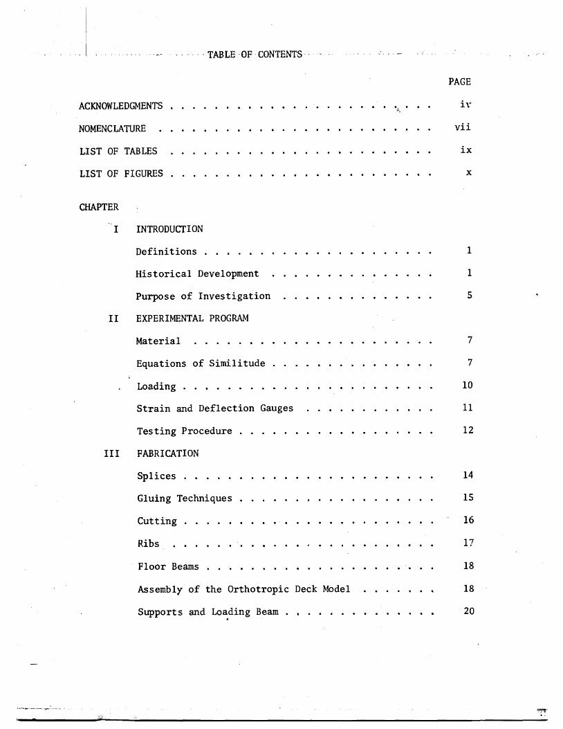
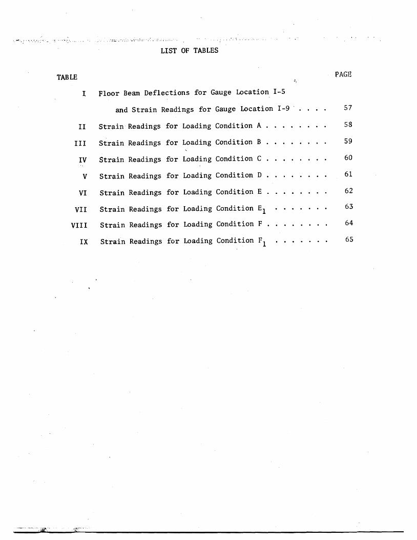
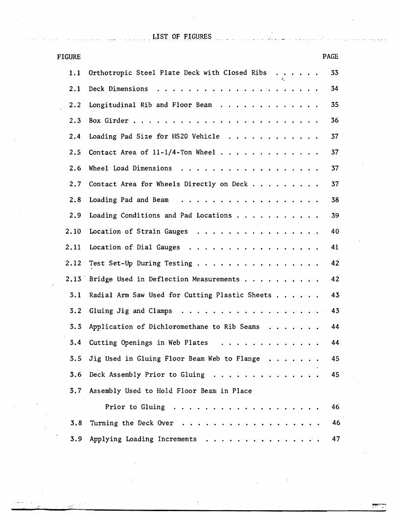

2
(a) A slab which transmits the loads to a series of longitudinal
beams called stringers or ribs (b) Stringers which are carried by
floor beams (c) Floor beams supported by the main girders (d) Main
girders which transmit their load to the bridge supports The main
disadvantage of this type of design lies in the fact that each element
is thought to fulfill a separate function resulting in wasted material
and an increase in the dead weight of the bridge Actually the above
elements of the bridge system resist the load as an integral unit when
a load is placed at any point on the bridge the decking and floor
beams distribute it to the main girders in proportion to the relative
rigidities of the different parts of the structure
The first bridge that utilized the deck plate stringers (ribs)
and floor beams acting together was an overpass at Jungingen Germany
in 1934 true economy however was not achieved because the deck and
main carrying members were analyzed as separate elements The main
advantage was its shallow depth which gave it a slender appearance
During the same decade the American Institute of Steel Construction
was experimenting with a similar type of deck construction known as the
battledeck floor It was from tests conducted at Lehigh University on
scale models that a greater reserve strength than that predicted by
bending theory was found in the deck plating (23) It was not until
after World War II when due to a shortage of steel and a need to
replace many long span bridges in Germany that the full economic
realization of orthotropic design was recognized The deck was
3
considered to fully participate in the sttess of the main carrying
members of the bridge
The first bridge using this concept was the Kurpfalz Bridge over
the Neckar River in Mannheim Germany which was opened to traffic in
1950 (19) Other important l~ng-span bridge structures followed in
quick succession But it was not until 1960 that work was begun on
the first orthotropic deck bridge in the Western hemisphere with the
Port Mann Bridge over the Fraser River in Vancouver BC Canada (13)
In the United States the Poplar Street Bridge over the Mississippi
River in St Louis Missouri (22) built in 1966 spurred interest in
orthotropic bridge construction and other bridges of the same type
followed Major orthotropic bridges recently completed in the United
States are the San Mateo-Hayward Bridge across South San Francisco
Bay (8) the San Diego-Coronado Bridge (1) and the Fremont Bridge in
Portland Oregon (14) which is nearing ~ompletion
Long before the advent of orthotropic deck bridges theoretical
studies were conducted on orthotropic plates The first mathematician
to address the problem of anisotropic bodies was Cauchy (4) who in
his paper published in 1828 gave generalized elasticity equations
The first application of the theory of anisotropy to a structural
element such as a plate was attempted by Gehring (11) in 1860
Other theoretical investigations were carried out by Boussinesq (3)
1879 Voigt (25) 1910 and Geckeler (10) 1928 The first comprehensive
4
tteatment of orthotropic plates was presented by Huber (16) in 1914
It was from his works that the solution to orthotropic plate problem
was developed The following equation known as Hubers equation
gives the relationship between deflection and loading
b 4 4 w _ + D r w = P(xy) [11]+ 2H~ ex uy Yb y
4
This is a non-homogenous differential equation because the deflection w
does not appear in the function P(xy) D D and H are the rigidshyx y
ity coefficients while the function P(xy) is the loading intensity at
any point The solution involves first solving the corresponding
homogenous differential equation where P(xy) = 0 and superimposing
this general solution with a particular solution of the non-homogenous
equation The result will vary depending on the relations between the
three rigidities D D and H x y
To treat a stiffened plate as an equivalent orthotropic plate
an assumption is generally made that the spacing of ribs is small
relative to their length between supports In 1946 Guyon (12) proposed
a method of applying orthotropic plate theory to a bridge deck this
was followed by Massonnet (17) who took into account the effect of
torsional rigidity It was in conjunction with the design of the
Cologne-Muelheim Bridge in 1951 that Cornelius (6) first applied
Hubers equation to the problem of computing stresses The most successshy
ful method of th~ application of Hubers equation was developed by
5
Pelikan and Esslinger (21) This method was adopted in the AISC Design
Manual for Orthotropic Steel Plate Deck Bridges (2)
Although there appears to be an abundance of theoretical studies
on the subject of orthotropic plates experimental investigations
known to date most of which have been conducted in conjunction with
the construction of major orthotropic bridges are somewhat limited
Such tests have been carried out in different countries primarily on
prototypes To overcome both physical and economic difficulties of
testing prototypes model tests on bridge structures have been successshy
fully utilized by several investigators Heins and Hails (15) used a
curved stiffened plate model to show the validity of the mathematical
model and the resulting computer program for a bridge with curved
girders Naruoka Okabe and Hori (20) made an experimental study
of an orthotropic bridge model with torsionally soft ribs to check
a proposed mathematical model Troitsky and Azad (24) built and
tested a plastic scale model of an orthotropic box girder with open
ribs
Purpose of Investigation
A two year-study of the behavior of torsionally stiff orthotropic
decks was conducted recently by Erzurumlu and Toprac (9) The
experimental program consisted of prototype tests of deck panels
simply supported by unyielding floor beams In contrast this thesis
evaluates the response of a multiple panel deck supported by flexible
floor beams In order to establish further confidence in the discrete
6
element model and computer program proposed by above investigators
to simulate highway loadings and to keep experimental costs to a minishy
mum a scale model of plastic was considered to be the most appropriate
The object of this investigation may be summarized as follows
(1) To develop adequate scale modelS of plastic for
orthotropic steel bridge decks continuous over flexible
floor beams
(2) To verify the adequacy of a discrete element computer
program (18) used in Reference 9 by subjecting the
bridge model to AASHO vehicle loadings
CHAPTER 2
EXPERIMENTAL PROGRAM
The dimensions of the model to be investigated were chosen so
that a two-lane steel orthotropic bridge deck would be simulated
The material sizes were selected on the basis of availability of
plastic sheets Although the primary objective of the investigation
was not to simulate an existing deck the dimensions as shown in
Figs 21 through 23 with the exception of the box girder fell
very near those of the Poplar Street Bridge (22) and the Fremont
Bridge (14) when a scale factor of 4 was applied
Material
The material used was AcryliteR an acrylic sheet manufactured by
the American Cyanamid Company in Wayne New Jersey Its chemical name
is poly(methylmethacrylate) The modulus of elasticity was determined
by standard coupons taken from the plastic sheets used in fabricating
the deck Its average value was found to be 394 ksi The Poissons
ratio was taken as 035 as suggested by the manufacturer
Equations of Similitude
Principles of similitude governing structural models are well
documented (26) Structural models may be classified as direct and
indirect Direct models are made of the same material as the prototype
and simulate the true response of the prototype including ultimate
strength On the other hand indirect models simply represent the
8
response of the prototype within the elastic range and need not be
fabricated of the same material as the prototype
To illustrate the basic relationship governing the similitude of
geometry and loading the following eqUations are provided for the sake
of clarity By using a scale factor of 4 all lengths in the deck model
are one-fourth the lengths of the prototype
L Lm =-pound
4 [21]
where Lm = length in the model
L = length in the prototypep
Using the same reasoning model deflections are one-fourth the protoshy
type deflections
= L~p [22] ~-~ m 4
where 6 m and L~ p are deflections in the model and prototype respecshy
tively
Strains are related by the strain scale factor
Sf = Epl Em
where Sf = strain scale factor
E = strain in prototypep
E = strain in model m
Considering the deformation lj of a small fiber of some length J on
the tensile side of a beam section
9
[23]6 p = ~ Jp
6 m = fm 1m [24
By substituting Eqs pound21] and [22] into [24]
L ~= [2 S]tm --t4
The substitution of Eq [23] into Eq [25] gives
[26]ip = ~
Therefore the strain scale factor equals one in a true model where
strains at corresponding points in model and prototype are equal
provided the loads are scaled properly
~
Since SE = ~ = 1 loads can be scaled using the following relationshy
ships
p = 6 AP P P
~ =~ and m E m
A EA = m (4) 2
where A and A = areas of the model and prototype respectivelym p
E and E = the modulus of elasticity of model and prototype m p respectively
6 and 6 = the stress in the model and prototype respectivelym p
P = load on the prototyPep
10
From which
[27]Pp = [CAm)4J [Om ~J Since P = (5 A m mm
P E S =-E = (4)2 -pound [28]p P E m m
where S = load scale factorp
P = load on the model m
If the modulus of elasticity of steel is 29000 ksi and that of plastic
is 394 ksi then
P P = -Es = (0000849)P [29]m pp
This means that a load of 100 lbs used in the model test is equivashy
lent to a 1178 k load on the prototype The total weight of one H520
truck is 72 k (Fig 24) (1)
Loading
Scale models of actual trucks would require a minimum length of
7 ft on the deck Because the length of model deck was only 12 ft it
was considered sufficient to simulate only single whe~l and axle loads
The size of t~e loading pad was taken as 6 in by 25 in which is
equivalent to an AASHO HS20 truck wheel contact area (Figs 25 26
and 27) This area is determined assuming that the tire is in direct
11
contact with the deck plate without considering pavement thus represhy
senting the worst condition for local stresses in the vicinity of the
loaded area The applied load was transmitted to the deck through a
l2-in neoprene pad and a steel plate as shown in Fig2S A summary
of all loading positions is shown in Fig 29
Strain and Deflection Gauges
The strain gauges used were Micro-Measurements Inc EA-06-2S0BGshy
120 which are general purpose gauges intended for static and dynamic
stress analysis To overcome the heating problem and the resulting
errors caused by the poor heat sink quality of plastic a method of
pulsing which will be discussed subsequently under testing procedure
was used
The positions of the strain and deflection gauges are shown in
Figs 210 and 211 respectively The gauge installation procedure
as suggested by the manufacturer was followed closely After installashy
tion a piece of cellophane tape was placed over each gauge to protect
the lead wires All lead wires were cut at equal lengths (12 ft) to
ensure that variable lead resistance would not be a factor during
testing The strain gauges were monitored by a Datran II strain recordshy
ing system which consists of a Model 1330 lO-channel scanner a Model
321 strain indicator and a Franklin 1200 Hi-Speed Printer (Fig 212)
A gauge factor of 210 was used for all strain gauges
Deflections of the deck were measured with dial gauges to an
accuracy of 0001 inch The gauges were mounted on a bridge supported
12
on two sides by metal stands (Fig 213) Support deflections also
were monitored and used later to obtain corrected span deflections
Testing Procedure
In testing ~odels madamp of plastic two problems are encountered
which are not significant in metal modelS (a) As mentioned earlier
the temperature of the strain gauges increases due to the insulating
characteristics of the plastic (b) A significant amount of creep occurs
To avoid heating strain gauges weteonly activated during an
actual reading In this manner the presence of current in each circuit
was limited to just a fraction of a second To efficiently take the
readings the Franklin 1200 Hi-Speed Digital Printer was connected to
the strain indicator thereby enabling all ten channels to be read and
recorded within one second
In tests conducted on independent specimens it was found that
significant creep occurred immediately after the application of a load
These tests also showed that after approximately five minutes 95 percent
of the creep had taken place therefore it was decided to take all
readings after a five-minute pause a procedure followed in determining
the value of the modulus of elasticity The testing procedure was
as follows
1 Take initial strain and deflection gauge readings
2 Start timer
3 Apply weights
4 Take immediate readings
13
5 Wait five minutes
6 Take readings
7 Apply next loading increment and repeat cycle until
five increments at 20 pounds each have been added
By using 20-pound increments a total of one hour was necessary to
complete one test as the deck was unloaded the same way Figure 212
shows the complete set-up during one of the tests One person took all
dial gauge readings which were called out to a recorder to reduce the
chance of error
CHAPTER 3
FABRICATION
The orthotropic deck model was built of standard ll6-in and
lIB-in thick sheets of acrylic A laboratory check of these thickshy
nesses revealed that the 116-in sheets were 0061 in thick This
value was used in determining the section properties of the deck model
All connections were made by a gluing process thus simulating welds
in an actual steel deck Prior to fabrication of the model test beams
were built using proposed gluing techniques These beams were subjected
to heavy loadings which verified the adequacy of the welds Due to the
unavailability of desired lengths of material splices were required
Splices
The deck plate required a l2-ft x 6-ft sheet of liB-in acrylic
but the largest size available locally was 10 ft x 6 ft Therefore
a splice two feet from the end of the deck was considered Because the
10-ft x 6-ft sheet was 6 in oversized the splice actually occurred
lB in from the end midway between the last two floor beams This was
considered acceptable as the splice was 3 ft from the points being monishy
tored and in an area where the stresses were low
In order to provide continuous ribs a l2-ft length of 1l6-in
material was needed Again the maximum length that could be purchased
locally was 6 ft Under the circumstances it was determined that a
center splice in the ribs would be acceptable as the deck plate is
15
continuous over the rib splices The tie girder splices were made 18 in
from either end and staggered so that no two splices would coincide
All splices were made butt-joint style When a good fit was
obtained dichloromethane was used as a bonding agent where there were
inconsistencies in the fit PS-30 was used
Gluing Techniques
Dichloromethane a capillary action solvent that produces a medium
strength joint can be used only when parts are closely fitted with
no visible gaps The solvent is applied with a hypodermic needle along
the edge of the joint Capillary action draws the solvent between the
parts softening and swelling the plastic which then permits actual
cohesion of the parts After approximately five minutes the solvent
evaporates leaving a hard J clear joint It was found that a thickened
solvent could be produced by dissolving 3 percent clean plastic chips
in the dichloromethane This more viscous solvent had bonding charactershy
istics similar to the unthickened solvent but was more manageable when
applying
PS-30 a highly viscous polymerizable cement has little or no
solvent action and produces good joint strength after four hours
PS-30 comes in two components A and B Component A is a viscous solushy
tion consisting of a monomer and a polymer while component B is the
catalyst The shelf life of both components is six months the pot
life is only 25 minutes Before mixing the components should be
16
allowed to warm to room temperature for 12 to 24 hours Proportions
required to make PS 30 are
Component A 9S grams or 9S cc Component B S grams or S cc
After stirring for two minutes the mixture was applied to the joint
with a 13 gauge needle and 30 cc syringe
Although it is recommended that a V-type joint be used in conjuncshy
tion with PS-30 for maximum strength because of the small thickness of
the parts no V-grooved joints were used during fabrication PS30
was used only to overcome natural nonconformities in fit
Cutting
The plastic sheets were cut to size by a 10-in radial arm saw or
a l2-in table saw with a No 88 plywood blade To avoid handling the
deck plate it was trimmed to size in place using a 7-in Skillsaw with
a plywood blade
The l-12-in strips used for the rib bottoms were cut on the
radial arm saw (Fig 31) Out of 24 strips cut four were determined
to be unsuitable for use and had to be cut again due to a variance in
width For cutting the 3-in rib webs the blade was set at a 14 degree
angle providing the beveled edge needed for a proper fit to the rib
bottoms and the deck plate (Fig 22) Of the first six strips cut this
way three had to be discarded as they were as much as 14 in out of
alignment At this point it was decided to use the l2-in table saw
to ensure a better edge alignment
17
A total of 44 rib sides and 22 rib bottoms were cut To assure
that the ribs would be 12 ft in length when glued together two sides
and one bottom were bundled taped and then measured and trimmed off
in 6-ft lengths with the radial arm saw
Ribs
In order to hold the rib sides at a 14 degree angle while gluing
to the bottoms an eight-foot gluing jig was constructed to adequately
accommodate the 6-ft rib lengths (Fig 32) Foam rubber 12 in thick
by 1-12 in wide was laid on the bottom of the jig to provide a spring-
like effect so that the rib bottom plate would conform to the rib webs
during the gluing process The following step-by-step process was used
in the fabrication of trapezoidal ribs
1 Lay I-l2-in plastic strip on foam rubber pad
2 Place a I-in by l2-in wood strip on top of the plastic
strip
3 Compress foam pad and clamp in place using large C
clamps (Fig 32)
4 Place rib webs along the two edges of the wooden jig on
the rib bottom plate
5 Using small C clamps fasten rib sides to sides of gl~ing
form (Fig 32)
6 Release large C clamps allowing foam rubber pad to gently
push the rib bottom against the rib webs making a firm
contact
18
1 Apply dithloromethane to inside edge of rib using a hyposhy
dermic needle (Fig 33)
8 Wait 30 minutes then release small C c~amps and remove
finished rib from jig
9 Inspect rib for any opening along line and if necessary
reseal with PS-30
Floor Beams
Fabrication of the floor beams consisted of four steps
1 Cutting 8-in by 6-ft strips for web plates
2 Cutting openings in the web plates as shown in Fig 34
to accommodate the continuous ribs
3 Cutting five lIS-in x 2-l2-in by6-ft flange plates
4 Gluing flanges to the web
Some problems were encountered in making the web openings for the
floor beams The sides of the 3-in deep openings were cut with a radial
arm saw while the 1-12 in bottom was cut with a coping saw The same
technique as in gluing the ribs was used to glue the web to the flange
The flange was placed on a foam rubber pad and a series of clamps were
used to form a jig to keep the web upright (Fig 35) Small wedges were
then slipped under the foam pad where needed to provide the proper fit
Gluing was accomplished by applying dichloromethane to both sides of the
web No PS-30 was needed
Assembly of the Orthotropic Deck Model
After the fabrication of all the basic elements of the orthotropic
19
deck model was completed it was extremely important to follow a well shy
planned sequence of assembly steps The protective paper was first
removed from the deck plate and the ribs were placed on the deck in
their proper positions To provide a means of pushing the deck plate up
against the ribs a large foam rubber pad was placed under the deck (Fig
36) The ribs were positioned by using the notched floor beams as
spacers When all ribs were in their proper position weights were
applied at various locations to provide a tight fit Again wedges were
slipped under the pad to help make the deck conform to the ribs All
ribs were checked visually and with a thin feeler gauge for proper connecshy
tion to the deck The ribs were kept tight against the floor beam
notches by means of thin wooden wedges which were manipulated by a 7-ft
pole with a hook on the end
Pursuant a lengthy process of assuring that every piece was
properly positioned and fitted ribs were glued to the deck using
dichloromethane This assembly was left undisturbed for 24 hours after
gluing before removing weights and floor beams Checks were made for
places that were not welded properly and such points were reglued
using PS-30 After the rib plates were spliced at mid span the floor
beams were repositioned over the ribs More filing of floor beam webs
was needed in order to obtain a Eroper fit In the event of some gaps
(116plusmn in) which were too large to bond with PS-30 J small plastic
wedges were inserted prior to gluing In order to keep the highly
viscous PS-30 from pushing the wedges out during application dichloroshy
methane was used to spot-weld the wedges in place before applying PS-30
20
The floor beams were held in place during the welding process by
heavy steel bars lying over the tops of the ribs and clamped to supports
at each end (Fig 37) Weights were placed on top of the beam flange
to help hold it against the ribs The floor beam was then welded to the
ribs and deck plate After all floor beams were in place the deck was
turned over to check the reliability of the welding (Fig 38)
When it was determined that the welding of basic deck elements was
adequate the model was again turned over and the tie girders were added
The inside web of the tie girder was welded to the deck and floor beams
first The outside web was then installed followed by centering the
flange and welding with dichloromethane The total weight of the
finished assembly was approximately 125 pounds
Supports and Loading Beam
The model deck was simply supported on four corners by 2-in by
3-in steel plates (Fig 21) Two of these plates were placed on fixed
rollers (simulating a pinned joint) while the opposite pair was placed on
standard rollers
The loading beam consisted of a 10-ft aluminum H-shape supported
at loading point or points Two weight hangers were provided on each
end of the loading beam Each calibrated weight consisted of a fiveshy
pound chunk of caulking lead During testing a number of weights were
hung from the loading beam to obtain the desired load (Fig 39)
CHAPTER 4
TEST RESULTS
The Computer Model
A discrete element model capable of handing orthotropic plate
problems (18) was used for the analytical part of this investigation
The model (Fig 41) represents the stiffness geometry and support
conditions of an orthotropic plate continuous over flexible floor
beams The -principal features of this method include the representashy
tion of structural members by a physical model of bars an~ springs
which for analysis are grouped into two orthogonal systems of beams
and replacing the differential equations for orthotropic plates by
their finite-difference equivalent The problem then is reduced to
solving a large number of simultaneous equations rather than one complex
differential equation The computer program developed from the above
model permits the stiffness properties of the orthotropic deck and
floor beams to be included on an individual basis -thus resulting in
a more realistic representation of the bridge deck as an equivalent
orthotropic plate The bending stiffness of the plate in the x- and
y-directions and the Poissons ratio effects are represented by elastic
blocks at the nodal points (Fig 42) Support conditions are simushy
lated by elastic springs of appropriate stiffness at each joint while
twisting stiffness is modeled by torsion bars connected to the rigid
bars between elastic nodal blocks
22
Member stiffness and load values are entered in the ~omputer
program by first dividing the slab into increment widths of hand h x y
in the xmiddot and y-directions respectively Figure 43 shows the coordishy
nates of the deck model under investigation A joint is defined as
the intersection of the station lines in each x- and y-direction while
a mesh is understood to be the area surrounded by four jOints Or~hog-
onal flexural stiffnesses D and D are entered on a per unit width x Y
basis The torsional stiffness H is input on a unit width basis for
each mesh its value is determined with the aid of a separate computer
program following the method in reference (2) A listing of this proshy
gram is provided in Appendix ICa) Applied loads are assumed concenshy
trated at each joint therefore a distributed load must be proportioned
among the surrounding joints on a tributary area basis Unyielding
upports are simulated by introducing very stiff springs (500 kin)
at the joints on the support station line Discrete members such
as floor beams and girders can be entered on an individual basis by
giving their total stiffness values A typical computer output is
given in Appendix I(b)
Idealized Sections
The only function of the tie girders was to provide a flexible
support for the floor beams Therefore no attempt was made to properly
scale the tie girders~ as in an actual bridge their span lengths and
cross-sectional dimensions would be much greater ConsequentlYI
theoretical investigations by Chwalla (5) on determining th~ effective
23
width of the deck acting as the top flange of the tie girder could not
be used Instead this effective width was determined experimentally
by measuring girder deflections for several symmetrical loading condishy
tions and computing the required inertia needed to obtain this deflection
The tie girder inertia value was found to be 4434 in4 which corresshy
ponds to an effective deck width of 20 inches
The effective widths of the orthotropic deck plate acting with
a rib and floor beam were computed using the method outlined in the
AISC Design Manual (2) and others (23) It was determined that because
of its narrow width the tie girder would offer little or no rotational
restraint for the floor beams this justified using the full length of
the floor beam as its effective span when computing the effective
width All idealized sections along with corresponding inertia and
stiffness values are shown in Appendix II
Calculated vs Observed Deflections and Strains
(a) Deflections All deflections were corrected to account for
support movements during loading This was done by using a linear
interpolation of the settlements between supports Although a biaxial
stress field exists in the rib plates the use of uniaxial strain
gauges to determine strains at rib bottoms was justified through
experimental observations made by Erzurumlu and Toprac (9) Linearity
checks were made on deflections and strains for all loading conditions
prior to plotting any profiles
computed and measured center floor beam deflections are shown
in Figs 44 through 49 for all loading conditions At this juncture
24
it should be noted that the mathematical model does not account for
shear deformations The deflection due to s~ear was computed for a
lOO-lb load applied at the center of the floor beam and was found to
be 0023 inches If this correction is applied to the computed deflecshy
tions of Fig 44 the correlation between computed and measured
deflections would be very good with the difference reduced to less than
one percent Examination of floor beam deflection curves for other
loading conditions indicates that when the load is not directly over
the floor beam there is closer agreement between computed and measured
values This substantiates the need for a shear deflection correction
on floor bearns as less shear correction would be needed for smaller
floor beam loads It is interesting to note that good agreement exists
between computed and measured deflections at the tie girder as long as
the load is symmetrically located however as Figs 48 and 49 indishy
date a difference of approximately five percent exists when loads are
positioned in the driving lanes Thus the tie girder inertia value
and corresponding effective deck width are dependent among other things
upon the position of the load which is what Chwallas (5) theoretical
investigations indicated
Good agreement exists between experimental and computed deflecshy
tions of the ribs in Section 1-1 (see Fig 211) for the loading condishy
tions shown in Figs 410 through 417 Generally measured deflections
are slightly more than those computed with the difference seldom
exceeding five percent Again shear deflections may account for
25
some of this discrepancy as the difference is usually greater in the
center of the deck or directly under the loading pads Another possishy
ble cause of discrepancy is the localized distortion effect in a rib
produced by the moving together of the deck plate and the bottom rib
flange resultingmiddot in a lowered moment of inertia and section modulus
when a rib is under load In Fig 411 the computed deflection
directly under the load is greater than the measured deflection This
behavior is believed to be caused by the fact that the wheel load is
input as a point load due to the limitation of the mesh size Because
the 6-in long loading pad is centered over a node it cannot theoretishy
cally affect adjoining nodes In actual behavior however the load
is distributed to some extent to the adjoing nodes thus accounting
for the difference between measured and computed deflections on the
adjoining ribs An examination of Fig 417 reveals the same type of
loading condition resulting in the same relationship between computed
and measured deflections The extent of the discrepancy is not great
in this case as the load on each node is only one-half that of Fig
411 Generally when the load is over the floor beam the rib action
is fairly uniform (Figs 410 413 415 and 416) When the load
is in an adjoining panel centered between floor beams (Fig 412)
there is a slight rise in the center rib The decreased magnitude
of the computed deflection again is due to the load being input as a
point load A check of the strains at this point both theoretical
and measured reveals that the bottom fiber of the loaded rib is in
compression In contrast the adjoining rib bottoms are in tension
26
and thus verify the shape of the curve The deflections and strains
for computer coordinate (66) (floor beam bottom) are given in Table I~
Deflections again vary depending on the position of the load with the
greater percentage difference being when the load is near the floor
beam
(b) Strains Overall strains vary anywhere from 1 to 49 percent
with computed values generally higher than measured values The large
discrepancy between computed and measured strains is probably due to
the following causes
1 Instrumentation error
2 Warping of the deck due to uneven support settlements
3 Idealization of the structure as a discrete element
model
4 In the case of ribs the assumption of a uniaxial
stress field in the rib bottoms
The instrumentation error could be as high as ~20 ~inin
and would account for a larger percent difference between computed and
measured values in low ranges Therefore readings less than lOO~inin
would be too small to verify the adequacy of the discrete element comshy
puter pr~gram
The warping effect could also cause plus or minus strain errors
depending o~ the magnitude andlocation of the sUPPQrt s~ttleIlJ~nt$
27
A safe assumption is that the more warping the greater discrepancy
between computed and measured strains As an illustration referring
to Table I the 30 percent difference in loading condition F could
be due to warping because of the unsymmetrical loading in that case
An examination of the support deflections reveals that Gauge No 7
drops 0049 in while the diagonal corner Gauge No 9 drops only 0011
inches This indicates a warping effect and a possible explanation of
the 30 percent discrepancy
While the accuracy of the discrete element model could be
improved by using a finer grid the mesh size chosen was considered
adequate for the purpose of this investigation and prevented excessive
use of computer time Because the theoretical data generated for
deflections and bending moments are average values there will likely
be some differences between experimental and computed values The
errors introduced by assuming a uniaxial stress field in the rib
bottoms would have some influence on the computed versus measured
relationship which would be more apparent when the ribs are heavily
loaded
Computed and measured strains for most loading conditions are
given in Tables II through IX Keeping in mind the previously
mentioned possile sources of error there is generally a good agreeshy
ment bet~een theory and test results It is interesting to note that
when a load is directly over a rib (Tables III and VIII) the computed
strain is considerably greater than measured strain--38 to 49 percent bull ~ ~
28
This can be partly attributed to the load being input as a concentrated
load and partly to the excessive distortions of the rib plate directly
under the load This localized distortion effect was also noted in the
investigation reported in Reference (9) A check of the floor beam
strains near the girder (Table II) Gauge 1-7 indicates there is tension
present at that location Although the strains are too small to be conshy
clusive it indicates the assumption made earlier which stated that
the tie girder offered little or no rotation restraint for the floor
beam was reasonable
It could be concluded that within the limits of the experishy
mental program the orthotropic deck responds as predicted by a discrete
element computer program in the elastic range
1
CHAPTER 5
CONCLUSIONS AND RECOMMENDATIONS
Conclusions
In view of the findings documented in Chapter 4 it may be conclushy
ded that
1 Plastic sheets of acrylic can be used as a modeling material
for the fabrication of orthotropic deck models Ordinary
woodworking tools are effectively used in the deck construcshy
tion thus keeping costs to a minimum
2 Dichloromethane and PS-30 are compatible an~ effectively
simulate welds in steel orthotropic decks when tests are
conducted within the loading range of this investigation
3 Creep effects of plastic do not adversely influence test
results when proper testing procedures are used
4 Indirect models can be constructed from plastic acrylic
material to test structures as complex as orthotropic decks
5 The discrete~element model proposed by Matlock and Panak (18)
is effective in predicting the moments and deflections
along grid lines of multiple panels of orthotropic decks on
flexible supports
30
Recommendations
Future investigations involving orthotropie bridge decks should l
based on this study be concerned with the following
1 A computer program using a finer mesh size should be run
on this model to see if the results would change signifi shy
cantly
2 The deck should be supported on concrete blocks so that
warping would not be a factor in recorded deflections and
strains
3 The box girders should be properly scaled so that a check
on its torsion restraint could be made
4 The model should be extended to a length such that a full
AASHO Highway vehicle could be simulated as a live load
5 Investigations should be conducted on the interaction of
the rib and floor beam by extensively gauging the areas of
intersection
6 Decks using different types of ribs (open biserrated etc)
should be modeled and their response compared with those
obtained from closed rib models
7 Orthotropic decks on flexible supports should be modeled
with steel as a means of checking the ultimate strength of
the system
REFERENCES
1 American Association of State Highway Officials Standard Specifications for Highway Bridges 1965 Washington DC
2 American Insitute of Steel Construction Design Manual for Orthotropic Steel Deck Bridges New York 1963
3 Boussinesq J V Complements ~ une Etude sur la Th~orie de lEquilibre et du Mouvement des Solides Elastique dont Certaines Dimensions Sont Tres Petites par rapporta LAutre Journal de Mathematique Paris 1879
4 Cauchy A L De la Pression dans un System de Points Materiels Exercices de Mathematique Paris 1928
5 Chwalla E Die Formeln zur Berechnung der vollmittragenden Breitediinner Gurt und Rippenplatten Der Stahlbau No 10
1936
6 Cornelius W Die Berechnung der ebener Flachentrag-Werke mit Hilfe der Theorie der orthogonal-anisotropen Platten Der Stahlbau Vol 21 1952
7 Engineering News-Record Californias Orthotropic Bridge Set to Go October 29 1964
8 Engineering News-Record The San Mateo-Hayward Bridge A Fabrishycation Dream June 23 1966
9 Erzurumlu H and 1oprac A A Research on the Deck Elements of the Ammi System Structures Fatigue Research Laboratory Report No P550-12 The University of Texas Austin March 1970
10 Geckeler J W Elastizitatstheorie anisotroper Korper Handbuck der Physik Band VI Berlin 1928
11 Gehring R De Aequationibus Differentialibus Quihus Aequilihrium et Motus Laminae Crystallinae Definitur Berlin 1860
12 Guyon Y Calcul des Ponts Larges ~ Poutres Multiples Solidaris~es par des Entretoises Annales des Ponts et Chaussees No V Septembre-October 1946
13 Hardenherg G J Design of the Superstructure of the Port Mann Bridge1f The Engineering Journal July 1961
14 Hedefine A and Silano L GI Design of the Fremont Bridge ASCE National Structural Engineering Meeting Portland
32
15 Heins C P and Hails R L Behavior of Stiffened Curved Plate Model Journal of the Structural Division Proceedings of the American Society of Civil Engineers Vol 95 No ST-l1 November 1969
16 Huber M T HDie Grundlagen einer rationellen Berechnung der kreuzweise bewehrten Eisenbetonplatten Zeitschrift des Osterreichischen Ingenieur - und Architekten-Vereines Vol 66 No 30 1914
17 Massonnet Ch Methode de Cal cuI des Ponts a Poutres Multiples Tenant Compte de leur Resistance ~ la Torsion Publicashytions International Association for Bridge and Structural Engineering Vol 10 1950
18 Matlock H and Panak J J A Discrete Element Method of Analysis for Orthogonal Slab and Grid Bridge Floor Systems Center for Highway Research Report No 56-25 The University of Texas Austin May 1972
19 Mayer R Die Kurpfalzbrucke uber den Neckar in Mannheimtt Der Stahlbau Nos 6 7 8 1952
20 Naruoka M Okabe T and Hori K An Experimental Study on Model Continuous Beam Bridge with Steel Deck Publications of International Association for Bridge and Structural Engineering Vol 18 1958
21 Pelikan W and Esslinger M Die Stahlfahrbahn-Berechnung and Konstruktion MAN Forschungsheft No7 1957
22 Shields E J Poplar Street Bridge Design and Fabrication Civil Engineering February 1966
23 Troitsky HS Orthotropic Bridges Theory and Design The James F Lincoln Arc Welding Foundation August 1967
24 Troitsky M S and Azad AK Bending and Torsion in Orthoshytropic Deck Box Girder Journal of the Structural Division Proceedings of the American Society of Civil Engineers Vol 98 No ST-9 September 1972
25 Voigt W Lehrbuch der Kristallphysik Leipzig 1910
26 White Richard N Similitude Requirements for Structural Models Conference Preprint No 469 ASCE National Meeting on Structural Engineering Seattle Washington May 1967
-
P
- () ~ -4 X ) -- tQ - 0 -I ftl
rshy ~ r 1gt
-1
C It (
~
~
shyo
Z g
- c o-Z
Ie
CP C
---
-
-n-G ~
0 1tI lt
0
t IfI Z J ()
Z P
I I
I I
I
I I
I i
I
-tshy I I t I ~
I I I I I
~
t ~
I r-shy
1-shy I I I I I I I I I I
I I I I
I I I
-
I
I I I
I I I
I I
Imiddot
-
bull shy0
--tshyI
I po U
Q r---shy 0
I i
~ 0
I
)0
~ omiddot-0 ~ T bull l
l
~LO II
OOlte
middotOOmiddot~middotmiddot---I
GLQ ~olt -rL1
OO~ 00laquo
gt o obull
tf
CNOIN~HIO
0 ~~HM 9middot21middotCJ1~ bullPti Z
JJd 1fO 1nJS 4MJ ~Q dOl H1 14
1 QJO01 d11t19ff
bullIampZ Ie I~ J~fianlt ~11aM flU iD dol 4tU J ~41~ JatlN~
(l~t1n4Ci( -amiddotl1f14 oN1
01 l7Z til
OJ oz z
01 Oll 9
CHWI
L$ C~HN
~ tdl Nt
dVO ~aHM
1g=3HM NaJ t11 -10 4-a~ l 11NO lt middot21middot)~ I
~JJM irtJ ~del erialJ 4211 J ~oJo ~1J
lfLNO ~1(11l1
~=3a1 IN=lfn~J ClJ10 llJltCnlt i3U (1110C odo 11 11lo~
OZltH --ao~ ~~IC d ~NIO~O 1z middot~Id
fa tt a oe 01 ---~l
Z~
01
~Yiq~~ ~a~rAJJlta
~ta ~o J~ ~fd ~
1 ~shy ()
~ 0 Id
lj~t43001~ N~~Ml~Q t+1r+1ML=aca ltofd d
CI 0
H1aq ~OG1-l -10 ~ clta Ia If CO vd ~
1 0
------
N k I
C () n -till J
~-9ca (1001 d) lY bull ltltlIa N~~Mll ltQ~d -
I~ raquo ~
1 ---1-- 0 f 111
)~
c ~aq 2I001-i N~~Ml Haca 7J001d -~Cd ~ C317J 11 ta~d -(f) -io bull ~I2J LV 011d bull
I 1)1 ---shy-PJ----4---+ 0
Q 9
AI
~-lf11 l J
--shy-~---t----- -
j~
0- lIf
--
-~ o
I Imiddot I I I I
I
I I sa I
bull- bull
tEl - - l=~ Abull -C)
bull ~
I II
I I I
I ta I ~ ~~ lar I j Il~ CP e 0
tIbull
~bull ~ -shy
[l ~ 1-1 -T
bull --1 bull bull bull -~ Jl 1 bull -abull ~ I I I I
~I I JQ
Ql I I I I ~ tf of(
Jl ~
tclXll~~4 1IDD~ _ I - r-
if bull(Jill i I
I
I I
I I
II
I
ot
---
-
II
G ~
-
r 0 ~ tgt
0 ~
Z
~
0 tgt r
G 1gt C lti
I I I I
I I
I I I I
I I I
I 1
-- _shy - - I
I I t
t I
I I I
I I I
1 I
o~ P~ t (~ lt1gt1= c~ bull bull Q )l ~ ~ -
i I
I shy
I I I I I
bull bull oa I
~
1Q I I I i 0 I I I I I - I-4
~
I
~amp~faq 2Joo -I -shy -I r J --1-shy I I I
I I I II
I
_L
ED CD agt
)02z[
lQ ()-C0 ~UQ
)
0 ~ It )10 U
-1-
U t J
t -0 0
42
Fig 212 Test Set-Up During Testing
Fig 213 Bridge Used in Deflection Measurements
43
Fig 3 1 Radial Arm Saw Used fo r Cutting Plastic Sheets
Fig 3 2 Gluing Jig and Clamps
44
I
Fig 33 Application of Dichloromethane to Rib Seams
Fig 34 Cutting Openings in Web Plates
45
Fig 35 Jig Used in Gluing Floor Beam Web to Flange
bull Fig 36 Deck Assembly Prior to Gluing
46
Fig 37 Ass emb ly Us ed to Hol d Floor Beam In Place Prior to Gl uing
Fig 38 Turning the Deck Over
( gJ ) 1=3COH JN~r~1-=3 1~-iZJca HOCl-i LNIOr 11dkl z-v middot91j
( qy) ~L~1d I d0211oHJ2IO -10 1aOH LN3H31~ JJ~ZJC(j -tJl-i
x~~~____________~
2
-r
middotat
x 2~ 1 01 ( ~a ~ C lt~ ~I 0 --u
-~ ~
~~ ~ f) middot)(4
D b-
~o
~4 t IU
1)1 G
J
-n I~flt)(~L1J) middotPN ~9H-(i ~
~ I -1 rT nn rrrr1 TTlVf- d)
bull ~ d~Or lID IIU IIJJ LUJ
)Y 0 (01 q ~V C1JC101
0
() shya r --hTIm I 1111 I~
l~ ~ I1II
D -0 -aN 00~O1 ~ tJ4 o~a ~o - c - -I P
ct 10 -~ lti -shy IQ
1
-) ----- _bull -tt -shy-t
-(p
0
~ 0
I)
-~ ~
~ P
~ ~ 61
0
~
~ ampgt p ~ tt Z 4 m ft
r () 0 F
0 ~ 1gt - ~
w r n ( -4-~ 7shy
r 0 Cgt 0bull ~ ()
7 C 0
bull () G to a
C -I Il 0
0
0 tI
r
0-
0 0-
- Q 0 I
0 I ~
0 0 00
I Z z ( r tT ~ lti
~ ~
- 0
( -l -I t -a 7 ( -4
11 r l1
r ()
~C ~---- ~ ~ shy ~ - 0 8~ ~ tIshy -
bullbull 0 1 0 0 lt) 0 r 1t ~ r (
t - -()
L
) P P ~ C)
Z P Jgto
0
p
~ 1 Qshy
~ s
l Z -4 n f)
r l 0 1
G ro P 1_ Q t( l r ttl ( -- ) Z
r (l 1gt
~ ( () Z 0 Q
() 0 0
()
i I
-
~~ -1)
-~
-~
~~ -
-~ ~
-a
-() II
()
U ~
-~ f(0 1gtshyt(J ~~ e w ~o 0
() C)
~ () -()
i I
9 ~
~
~ t1 L --I rt ll
r -
C) 0 1
~ w I_ 0 t
r w (
-- - -Q
Z
r ~ 1gt Q ~ 7 ~
~
1 r IT (
--
o~ I -z ( I It
~
~
~
~ -~
() shy
~ N l 0 () ~ U
LS
G - ~ 1
rshy)
~
$ 1gt
r shyo l -r r f(1
--l )
7
-
0 It 1 r It t - 0 ~ ~
-Z 0
~ I 0 O~ z I (
~ -~ ---] m ~
N ~
ii ~ 0 -ltP shy ()
IT 1 ~
t
)
~
~ -~
lt)
I
shy Gmiddot ~
-
r (J
It
Qrshy-~ t) l ~ ll () () 1
W bulli
rQ
1gtshyi
w~ r ft ( -t - 0 7shy
r ) 1gt ~ middot ) ~ Z
middot ~
n
- 9
-~ -J IT ~ --shy0 Z II-shy
~ n r
-4 )
z N Ol - fl 0
rshy r ~ Igt 0 ~ Z ~ l
~ Sl-() 0
~~ Ot i i
I shy~ a (l
~ 1)( c~ ((
wo u
0 fT shy
t) t) IT 0
~ 8~ 0 -l
(5 I ----I I Z C Z ( I (T
~ ~ ~ 0 ~
I J~ t1 (( --lshyshy( () 1gtshyZ ~ bull
U It
rshy bulltI shy-II =Jesshy ( --
l -I 0 z 8shy 0shy
fl ~
l (
0
rshy(l
r t) 1gt ~ bull ~
z ~
~ Jgtoo
~
~ o I
~ ~
-)l J
~ ~ 0 z
-I
0 tr -p r 11
n Q Z ~shy P ~ ta 0 1- r - r ~ 1gt ~ ( Q1 ~
(~ 0
t -0 C 0
0 fJ
rshy rn (
-~ ~ ~ -I 0 o 0 0 o bull ~ 8~ I I bull i I Z
--
1--shyZ ( I
-~ en ~ ~ ~
1 ~ -J ( -
0 z --
~C-~~O - f1I -~TI ~r
0II (
--- 0 ~ 0 ~l~ Z 0 1
1Q
Ibull
-~~~ I -~~ _1G -() 0
~o S
rshy f1
r C) 1gt 0 ( 0 Z -0
0
--s U C ~ 11 0
9
-l ( ~
-4shyt) z bull
- 0 n
rshy (t1
--l t) Z lQ
-0 -a fQ () r
r 0 ~
~ ( () Z ~
sgt
0 IT -n r IT ( -l
0 Z Z ( -t ff J
6 -I bull ~ S
N
0 0 ii ~
S) p ~ ~ ~ -0 0 6
8 o ~ 0 i I i I
~ ~ -~ U ft C
shy0 z -- - - Cl1
- r~ - lr-
-~ ( 11 0 1gt
to ) -0 C C f3 -t t Cl1 ~ 0
t~ shy 0 ()0 z
r
r ) 1gt ~ f ~ 7shy9 0
~ -J
t
(p ~
0
C
() 0 ~ 08~ o~
i
~ ~ -J shyl 11 ( -t 0 Z bull-~ rshy Il t ~ --- --I-~
() 7shy
N tl 0 P
Q lQ ~ ~ lt)
r ~
r Il (1 WI
r r 0 0 1gt tgt 0 ~ ( ( tgt a Z z 0 0
t ttl
I ~
1 (
o I
~ c ~ 1Q
ltV 0 Q
- ltY-o o 0 I
C
TABL
E I
FLOO
R BE
AM D
EFLE
CTIO
NS
FOR
GAUG
E LO
CATI
ON
1-5
FL
OOR
BEAM
STR
AIN
RE
ADIN
GS
FOR
GAUG
E LO
CATI
ON
1-9
LOAD
iNG
CON
DIT
ION
r
A
B
C
D
E
F
-
Com
po
Mea
s
Com
po
Mea
s
Com
po
Mea
s
Com
po
Mea
s
Com
po
Mea
s
Com
po
Mea
s
Def
lect
ion
(1
-5)
Inch
es
011
4 0
124
013
5 0
151
011
3 0
124
013
2 0
145
011
0 0
116
013
0 o
~42
Com
pute
d M
easu
red
091
0
89
0
91
091
0
95
09
2
iStr
ain
(I
-9)
Mic
roin
ches
17
5 20
6 61
8 53
1 15
7 17
3 44
6 38
0 12
2 13
7 33
8 26
0
Com
pute
d M
easu
red
-shy~-
085
1
16
----_
__
_
__
shy_
_shy
087
1
17
-_
shy
089
ff
13
0
P =
100
LBS
til
--
J
58
TABLE II
STRAIN READINGS FOR LOADING CONDITION A (1
I
~ (1)
cQ
~ 0 0
~
~ (1) +-gts (1) u
GAUGE NUMBER Computed u in in
Measured AI in in
ComEuted Measured
I-I 873 789 111
1-2 679 660 103
1-3 510 495 103
1-4 361 329 110
1-5 229 202 1 13
1-6 - 1-7 -
-- en
Jl 0 - bull
s 0 +-gt u (1)
til
11 3 205 208 099
11-6 202 229 088
11-8 194 199 097
11-9 183 173
-106
11-10 170 147 116
- -g g instruments
P 100 LBS
ji
I
59
TABLE III
STRAIN READINGS LOADING CONDITION B lt
~ (J)
Ql
~ 0 0 ~
~ (J) ~
53 u
Computed Measured Computed GAUGE NUMBER u inin JIJ inin Measured
I-I 599 599 107
~
1-2 486 495 098
shy
1-3 375 379 099
1-4 272 251 108
1-5 176 156 113
1-6 -
1-7 -
r- en
0
r-I ~ -
I
sect r-I ~ U (J)
U)
-11-3 2429 1635 148
11-6 453 593 076
11-8 238 242 098
11-9 202 174 116
11-10 -
Too small and within the range of tolerance of record1ng instruments
Wheel directly over rib P = 100 LBS
60
TABLE IV
STRAIN READINGS FOR LOADING CONDITION C 11
Computed Measured ComEuted GAUGE NUMBER ~ in in AJ inin Measured
I-I 587 500 117
1-2 601 559 108 I
i
I
~ 4)
CQ
ft 0 0 -c u ft G) +J
5 u I
I I
1-3 531 507 105
1-4 377 326 116
1-5 241 190 127
1-6 -
1-7 -
tI)
c c oi
-c
-c
s 0 +J 0 G)
U)
11-3 198 160 122
11-6 196 184 107
11-8 190 154 123
middot11-9 180 133 135
11-10 -------- shy -
Too small and- within the range of tolerance of record~ng instruments
P = 100 LBS
jl
~11~~---~middot
61
TABLE V
STRAIN READINGS LOADING CONDITION D 11
Computed Measured Computed GAUGE NUMBER u inin M inin Measured
I-I 424 397 107
1-2 427 439 097
a (J)
i
~ 1-3 378 389 097 ft 0 0
u 1-4 275 271 101 ft Q) +oJ s (J) 1-5 178 160 111u
1-6 shy
1-7 shy
11-3 341 293 116
~ 11-6 844 760 111 en c -t et J
II~8 832 731 114 t
s 0 11-9 260 220 118
-If +oJ
-0 Q)
CI)
11-10 192 159 121
Too small and within the range of tolerance of record1ng instruments
P = 100 LBS
c
62 ~ bullbullbull ~ - ~~ ~ ~ W bull
TABLE VI
STRAIN READINGS LOADING CONDITION E
Q)
eQ
Jot 0 0 u Jot Q) +Js Q) u
Computed Measured Co~uted GAUGE NUMBER ~ in lin AJ in lin Measured
I-I 435 395 110
1-2 558 514 109
1-3 495 478 104
1middot4 451 431 105
4241-5 380 112
1-6 206 165 125
1-7 -
(I)
c~ cx gti
I
6 ~
+J (J Q)
Cf)
11-3 185 152 122
11 6 196 181 108 bull
11-8 205 175 117
11-9 209 158 132
11 10 - Too small and wi thin the range or to1erance-of recorc1Jng
instruments P = 100 LBS bull
bull
63
TABLE VII
STRAIN READINGS LOADING CONDITION E1 2
Computed Measured C0RPuted GAUGE NUMBER u in I in M inin Measured
I-I 435 380 114
1 2 331 294 113
1-3 243 195 125
~ 1 4 169 138 122ltD co $-I 0 0 1-5 shy u $-I ltD +l 1-6 shy= ltD
u
1-7 shy
11-3 1
185 137 135
11-6 170 152 112 en
0 5 11-8 153 135 113 bull r 11-9 135 112 1200
- +l -0 ltD
Cf) 11-10 shy Too small and within the range of~ tolerance ofrecording
instruments P = 100 LBS
I
64 ooo _~~ _ bull
TABLE VIII
STRAIN READINGS LOADING CONDITION F
Computed Measured COIDEuted GAUGE NUMBER ~ inin~ ILl in lin Measured
I-I 317 265 120
1-2 388 346 112
1-3 349 331 105~ CD
bull cl
~ 0 0 1-4 313 292 107
14 ~
~ CD 1-5 282 243 116sCD u
1-6 shy
1-7 shy
11-3 309 357 087
~ 11-6 1343 975 138en I 0
c J
14 11-8 337 412 082 I
14
r 0 11-9 339 382 089 0 CD
CI)
11-10 1349 907 149
Too small and within the range of to1erance-or-recora1ng instruments
Load directly over rib P = 100 LBS
65
TABLE IX
STRAIN READINGS LOADING CONDITION F1
-Computed Measured Co~uted
GAUGE NUMBER ~ in lin AI in lin Measured
I-I 317 253 125
1-2 250 206 middot121
~ 1-3 191 146 131 (I)
al
ft 0 0 1-4 shy 11
tI
ft (I) 1-5 shys (I)
u
1-6 shy1-7 shy
11-3 309 331 093
U)
c II-6 197 180 109OM rt - 11
t 11-8 169 140 12111
s 0
OM 11-9 147 112 131CJ (I)
tI)
11-10 shy Too small and within the range of tolerance- of recordLng
instruments P = 100 LBS
- ~~ - - -~~ bullbull gt~~bullbull - ~
SDNI1SI1 ~DO~d ~31ndWOJ
I XION3ddV
67 ~ ~ ~ bull ~ ~ _~ a bull- ~
I(a) PROGRAM USED TO DETERMINE THE TORSIONAL RIGIDITY
JIDI 8-DIP11I O A IlIBCDO 1101
I I RIM THIS PROGRAII FIOS THE TOaSIGIIAL RlalDITY POil ORTlIOllIOmiddot I 11M PIC DICKS WITH fRAPIZOIDIL RSBS 3 RD II-THleDUS 0 tHE DICJCPLAtS I 6
IUQIJ TbullbullTHJCKIIUS O~ THB alB PLATa RDI A-WIDTH 0 TId IlIB ca) Rill la-SPACIIII or TRS RIBS (I
1aUDa DECK bull aIR H8-LH or 0N8 SIDI OF A RIB e-WIItTII 0 tal BASS or tHamp 81B 10 8M s-NODULUS 0 ILAITICITY I O-GDULUS O RIGIDifY S-ACTUAL SPACteO FLOOR 8EAMS 15 READ tlT8AIalWI_bullbull8aGS 80 u-eeHe+ 30 AlaquoAl8~H 0 K-CbullbullA-CtU(AItlbullbull pbullbull- 44 PRIWT -tHE tORSIONAL STII II CK-I--IP so 1CTImiddot3186e 1(Te~fl)middot3YO 10 LI(middotAI+8-CA1bullbulliB~I-CRImiddotAI~3CSImiddot8))OLI--H-CA-+AI--bullbull-aRI-AI-3 100 LLI~~CAI8Le)
10110 c(~a(AI) ce(~e(AJ-~AI)middotlaquo bullbullbullBI)CAIbullbullraquo)C8lC8A)
130 V-middotJtZImiddotfAI-C CAI+CI -(1~16I1-8 Vbullbull(ampI~A)middot3C(EImiddot(AIBLmiddot1150 V3eCLmiddotftlCAI)middota(IRI(H~A-CCI-bullbullCICbullbullCmiddotala160 v-vcveV3) 171 V-V I PRIIIT -Ha TORSI8IIAL RIIUCfIOactoR ISmiddotJV 110 HbullbullbullSC(Vbullbullbullbull)CA+Bl)) S PRIMT-IKE fOBSIOaAL RIGIDITY IS ca-I-I-bullbull 300 DAtA 115bullbull0e3bullbull 3bullbull 3bullbull 30311~19336bull bullbull9 DID
READY ItUN
AX SOPDI 33 fHa TORSIOIIAL ItJr-as II (Kmiddot middot) 19711 THZ TORSIONAL RIDUctlOM ActOR IS O1681~2 THE TORSIaAL RIGIDITY IS (XmiddotI-8IN 151906
il
68
I
Ieb) PROGRAM USED TO COMPUTE DEFLECTIONS AND MOMENTS
~R08 I LOAI) cobullbulllfttr- middot-middotnNE jHit(-lilrTifCNTEIt 0 OIctC Loio- bullbullbull lei
rAil I COttTrtOL DATA- - ---------------
__--y flkl NBIIt-_ -__ bull 3 I-
HOLO RO IRCpoundDtfC PR08 CI-HLt -0 bull - i ~I - HUtt CIRDS-UIJUT TftllltOI[[- I J ~ 4 __t bull
- rI8[ 2~ CGHSTDTrshy
NUM8pound1t 0 tNtItpoundENfS tN x middotDtrtpoundCTlormiddot middotxmiddotmiddotmiddotmiddot middotmiddotmiddotmiddotmiddotmiddot middotmiddotmiddot_middotmiddot middotmiddot-middot middotmiddotmiddot_middot-- middotmiddot -middot-middot--middotmiddotmiddot-----2 ----- middotmiddot-NUits-or-YNcRfMENfs IN dIRECTION My z
INCREMpoundNTLNGTH INX OmiddotIItfImiddot ttx - -- -- -middot-- -i-~middotjmiddotiabullbullbull shyINCItpoundIitNT LENGtH IN ot_poundCTtONmiddotH middotmiddotmiddot middotmiddotmiddot-middot middotmiddot-middotmiddot-middot- -middotmiddotmiddot-~ middotbullbullImiddot+middot
- ---- pbISS-ONS___lTro--- - I SLI8 TICtCNESS cfmiddotaimiddotmiddotmiddotmiddotiiilwmiddotptCljA[-M(hpoundN-fmiddottSmiddotCofllPUfeifmiddot----middot---------
--I spte lIEfJ ti_ tmiddot ncrIL STHSS _ -_-- __ _-_shy
rilL J JOINTmiddotSTIFFNESSINOlOIOmiddotDIT shy
- - - - ---_ JlY -middot middotmiddotmiddot-u_middot -_middot -- ----T----shytn OXmiddot TltU JOINT JOTNT
emiddotmiddotmiddot bull 1 2 middotmiddotmiddotT~-middotmiddot-rlr-Df-- ffJS-C 0middotmiddot-middot-middotmiddot---middot- --middot1---------middot --1middot------ -- -1 o 0bull middotmiddotImiddotmiddotIIJlr-IC-4poundr -1-~ --- ---- -0)---- - -- -- -_---- -----shy
D 24 II 24 -11ltl2 -496tGI -I -0 -I -Ibull __d -6-11middot-- 1 ----------- -----middotmiddotmiddotbullbullZ1--D----- -I ---------- shyJ -12-1 -middot-12-middotD~-middot----middotmiddotr----middot-middotmiddotmiddot---middotr-G7middotI-middot-I _ ---___-_ D II 12 II -1 -a 12fpound+G -0 -0 -0 111 r ---- bull-- --middotmiddot-middot-middot--middot-----lI7R middotT-middot--middotmiddot ----------bull(-- shy1 2~ rr-middot2~ middot-0-----middot--------middot--middot --middotmiddotmiddot-middot middot171poundbullbull[1middot-middotmiddot __middotmiddotmiddotmiddotmiddotmiddot -----bullbull------ --------shybull D I 2 -0 -D -a lffEf -I -I
-TI--TmiddotII-y-l~-middot----T-middot--middot --------------r7~bull - ---- ------ shy_ -- --- ---1 -I ------- --- - ---------T-n-shy
12 bull 12 1 -I -D -I -I -0 bullbull11112middot-ii-middot-z -0 _o-r bullbullbull bull~- ~ jbullbull bullbullbull
middotmiddot-ftmiddot middotmiddottt11 2O~ middot-a 0 ~ 0 -0--- - - - 112 _ - ----_ -__ - ----- --~- -- - -- _---- --~ -shy
fllEmiddot ~ middot JOIN SfI rsSAND LO AO 0 If- CONTlfmiddot-middot-middot-middot-----middot- middot ------------_____
--Iof middot_ltu middot Itbull it ~=~~t~~= ~~ ~ --J(-JOINT JOfNf
0 pound
-rAIL-middot----S1fSrl1NISStJIfImiddot--middot
middotmiddotlto -- TRU MESH -~poundSf
___J___ JI~_~]~ 2~_~ 19pound+IIJ
- raIL middot6~-middotlfjitmiddotmiddotSTlNpoundSS J ATA --~- - -- ---~ -- - ----shy
FROM fARO ---IAft BAitmiddot
n
---__----shy fI1 JSIY
--
__ __
69 l(b) PROGRAM USED TO COMPUTE DEFLECTIONS AND MOMENTS (Cont)
NONE
---------------------------------- shyraBLE 7 MULTIPLE LoaD OaTamp
FRO- lTIfRO--------- ---- ---- ----------- ----- shy Gil ~
JOt T JOINT
--- r-middotmiddot-f--------- -Iooa-II
_ --_ -- ----------~-----
---- ------------- --_------ _ _ ------------~----- ------_----shy
---1
ItOltaM SLag middotOpoundLDCI( -- -[NaUS - middot-middot--------middotmiddot-ltrfSlOijmiddotflffmiddot-O~middot-(jmiddot-69----IfaXIN~- -PTAOTlopIC OECI( iiiI 1973
LiSTie ORTHOTROPIC OEC( --------- -- -------- ~ -
I ------ ~- ----------shy
IItOB (COT ---j--- 0-=-IO=--C-ON=D=I=T=~~middotN---a=-_-9Neuro=_==HEJ _~o~D J_~_Jl~rIt~_F_)~c~ _l_~~()_u_J_M_ ___________
-------- --- _-__------------------------------__--_-------------shy-rAlIlE a USOCl
Staa MOMENTS aRE PElt UNtTMIlTH--middot------------------------------- shymiddot--~ara opoundNfS-i-RE TOTAL P~~ REa
X TWISTING MOMENT bull - TWISTING M(tEltT--middotmiddot----------middot---------------middot----- shy~- 8a aNGLES aRE COCICWYSEmiddotmiddot -~-
SLa x SLas - - --~-~- S( A-B ---(I~GESf- -- 9pound--- ~----------MOM- 0--middotmiddot- x ------ftttINctal xTO--shy8EA x 8poundIM Y TWISTING ~lA8 lARGEST s~
DrIP -- -OMENT-- MOpound --OMtff -OpoundT- - - OENT RpoundampCftON--------shy--~ - -~ ----- ------ - -- ------ shy-~--yen------~ -~-
bull -DIOE-I -211amppound-20 1Damppound-16 1214pound-0 124-O -40 ZSadE-aZ --- _ -6215E-15 3232pound-13 -- ----~ ---------- -------- shyr r~---2S65E-O middot 229I1E-0amp I ampE-13- _middot pound-06- - 9--middot------ shy
1~6~ D I - 2- -~ a06E- 358E-O GE-16 ~r9IE-6-2~209~6 - ~
- - - 10 UE-G 2 j middot3pound-1 1466E-OII 13SE-02 ft- middotr~--6 Z26E-0 3gE-O amp
1133E-2 -- I --Z-6-67E- -695E08
- -- fO SSpoundmiddot2 z4 -59~- 36 bullbullE-08--- - --- --- - - ---1061 pound-a 2
-------- -6167pound-1---1695pound-08 1085E-D2
- 2tt -6Z26pound-I - 3 ca-olt ~~ ------ ~ --1I31E-02 -516pound-1 ~5amp~~-UI - - -- -- 11 3fE -02
11- z~middot- D6E-t_-- 3S8E-D
a - - - 14IE-6 IS2E-d 937t~-07 -ijij O O~ - ~--- --- -- -- - ------ ---------- shyI E-16-2~ 6a9E-D7-2IIr~pound-7-2 9- I o Zbullbull35pound-16-71S1E-01 7 -01 -3-- crshyD----middot----------- shy2835E-16 3334E-14 361-18 -G ma ----- -- -shyO - 72~-a7( pound-07 --~ 3---0------- shy
_d bull 118-16 6041-07 2104E-a--29-~----o - - -~--------------
2815pound-1 -9112~-Ol 9JfIE-01 i44 d bull O ---------- ----------------- shy~ __bullbull-Cbullbull ~-ua ccipound-6 ~ I
IDI6E-D2 a n ---Z-216Jpound--4- 229iiE-~a I f~-16-3133Ea6 --- pound---- --r-bullbull
-----~------ ----726pound-03 - It ----- --- --------------------- ------ ---------- shy
ii
1300N dO S3Il~3dO~d SS3NddI1S
II XION3ddV
71
lt
12000 --middot--middot-- l~ fb ~PAcJ6 (j ~00 lb 00_
~~
~ FhshyN 1-- II II
~()
0 lIZ 12amp di
1fJ J 2 1r
IDfAlleO 5fCTON
L_~middot_90J ~
Aeamp ALItI) DI5TANGfXIV) A)((t) A)(f(n4) ( InA) 1A~L (In)
DE-C~ PLA1Eshy 2500 Oo~Z5 0 I~ OrxPJ7 Ooob2 ooJ~o
~f WampfS L lob 1F~40 J1(01 1 amp111 0middot174amp ~ eq2o 1---shy
~I[ ampoTTO~5 0274 ~oqAamp ob4CJ Z (1edJ 00001 2 middotftJZt7 c II2DEe W~ J Zooo 4 i~ampo b 2gt0 ~03t fOIft1f1~ 44middot11 (1l2D~rz PLAN6~S Of~lamp tgt t610 ~o7o 2amp t~tJ 00000 Z~middotJ~1
~ 7 Mz~ 14fO~12 - - 711070 -----~
I 1~ A~l middotl~ol0- (~tllr7(1 f)1)fJ 1-010 bull ~11J1
1 44 ~4 ft ~ilffNt~~ pound (~~LX44~) bull flAfeJ10middot It_tnt
fie nmiddot 11 E ~ 2DE fl ~T I r roN eeurogtgt
-~gt
U I ~L0 middot~~ s Ou1 qbLmiddot~-IL3middotlcemiddot
amp( LJlJ rA~1 e) fLea degfe WIYl
ILQ1~
Q1b o~
--shy0000
-QtbO~
tJO)L 9ltlt lJ
LJ~middotImiddotc)fL~
L91I
t J I~
ltJ~middotO
1 _shy~---
dJN1 d Holl
LOb or
I)J 00
(tLAI ) J~V+1
0t1J ll
1deg00
(U) 1
1O~q
of 00
(LA I) x ~
CJOb
c( r 0
(tU1) x~
ocgzft
tilJ())OmiddotO
LU) X NV1Cta
ltd9t7O -------
Cd~ -shy
V11c =3 111 dtJ3a
~u) V3~t4 - _-shy
r1 J~OO
--~-- ------------tl-shy---- f~1I t ~ L----------r-~---_J )ampItZ
73
J2A~H
l to
l d
-N ~
)(
10 E~L ED CbtC 1IoN
~ Ieampoj
lI~Lrb=====~ 111 I~
-g lIO
111 2s
1
DI~ANCf A2Eb(lrl1) 1 (t~4-)A~(rf) A~1 (In4) l+Ax(ln 40)X(m)
oo~13ooCo2amp 000(01 OOO~ODpoundG~ PLATr 1 ~amp fP o006f
w~e A 1Zampo4je~O amp~~siooo 2 2 ~AtqiloV~
Z S~6S 00004 20~4e8eoQ4b4F-LAN 6IE OSi~ b ifgt7
L 4~So~2 bCOfgt wmiddot7Egti -~ampe~4 -
10 ~ 4 ~ou (2 6~OX2 S~4J2 4~ ~o(o - 1 027
1 Z1 Z b 4
Flooe erA~ ~1ffNtegt~ cl - (~14-K27Zfraquo= o14e~o~ ~_Inf
rG n- ~ ampXTf rLi 02 F-ooe ~E-A ~ ~1 prN~SS bull
I
LAI JILoo 0 UI-~ ~ shy
Cib~f~ ~i~~ ~ (J-~I Xc ~ t
--UL b L ~ A J1) Imiddot~ lti lt1 l)Itt Q
Jtn -1 ~1 t~ (Ov IA~b~) 1~ ~~~N-I~ ult=
1 ) I 011 - elLA 1 -VLt1)O -1Loz amp
~(llteLoX~ca z f ) -tLo b OUt
tLO(j --~bo ftCl-hcSZ J ~ bebl ~ PJrLQo 00000 ~JLcao ot9Zo ~bo~ bOo Yi 0 LLod ctllZ)
ctQbif fq~z0 VdegVbO qbgso ltbta middot I b~ce 0 I
lt 93 A I ~l-a
11000 01000 rca-ooo ~btoo cvqoo bbLo ~Jv1d ~1~a
(UI) Jx~tI (UI) 1 (t-II ) 11)(~ (itAJ) X1 (tAl) X
~NVJla (zut) V=Jatl I
x
b~middot~ I J l
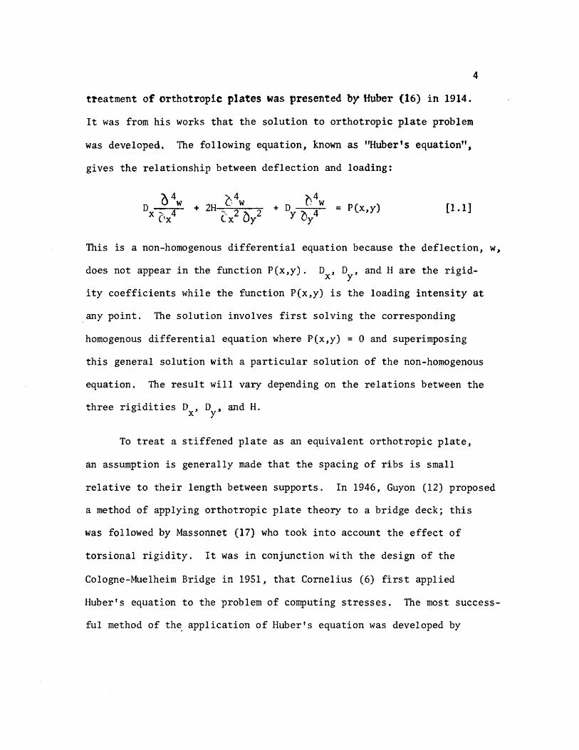
4
tteatment of orthotropic plates was presented by Huber (16) in 1914
It was from his works that the solution to orthotropic plate problem
was developed The following equation known as Hubers equation
gives the relationship between deflection and loading
b 4 4 w _ + D r w = P(xy) [11]+ 2H~ ex uy Yb y
4
This is a non-homogenous differential equation because the deflection w
does not appear in the function P(xy) D D and H are the rigidshyx y
ity coefficients while the function P(xy) is the loading intensity at
any point The solution involves first solving the corresponding
homogenous differential equation where P(xy) = 0 and superimposing
this general solution with a particular solution of the non-homogenous
equation The result will vary depending on the relations between the
three rigidities D D and H x y
To treat a stiffened plate as an equivalent orthotropic plate
an assumption is generally made that the spacing of ribs is small
relative to their length between supports In 1946 Guyon (12) proposed
a method of applying orthotropic plate theory to a bridge deck this
was followed by Massonnet (17) who took into account the effect of
torsional rigidity It was in conjunction with the design of the
Cologne-Muelheim Bridge in 1951 that Cornelius (6) first applied
Hubers equation to the problem of computing stresses The most successshy
ful method of th~ application of Hubers equation was developed by
5
Pelikan and Esslinger (21) This method was adopted in the AISC Design
Manual for Orthotropic Steel Plate Deck Bridges (2)
Although there appears to be an abundance of theoretical studies
on the subject of orthotropic plates experimental investigations
known to date most of which have been conducted in conjunction with
the construction of major orthotropic bridges are somewhat limited
Such tests have been carried out in different countries primarily on
prototypes To overcome both physical and economic difficulties of
testing prototypes model tests on bridge structures have been successshy
fully utilized by several investigators Heins and Hails (15) used a
curved stiffened plate model to show the validity of the mathematical
model and the resulting computer program for a bridge with curved
girders Naruoka Okabe and Hori (20) made an experimental study
of an orthotropic bridge model with torsionally soft ribs to check
a proposed mathematical model Troitsky and Azad (24) built and
tested a plastic scale model of an orthotropic box girder with open
ribs
Purpose of Investigation
A two year-study of the behavior of torsionally stiff orthotropic
decks was conducted recently by Erzurumlu and Toprac (9) The
experimental program consisted of prototype tests of deck panels
simply supported by unyielding floor beams In contrast this thesis
evaluates the response of a multiple panel deck supported by flexible
floor beams In order to establish further confidence in the discrete
6
element model and computer program proposed by above investigators
to simulate highway loadings and to keep experimental costs to a minishy
mum a scale model of plastic was considered to be the most appropriate
The object of this investigation may be summarized as follows
(1) To develop adequate scale modelS of plastic for
orthotropic steel bridge decks continuous over flexible
floor beams
(2) To verify the adequacy of a discrete element computer
program (18) used in Reference 9 by subjecting the
bridge model to AASHO vehicle loadings
CHAPTER 2
EXPERIMENTAL PROGRAM
The dimensions of the model to be investigated were chosen so
that a two-lane steel orthotropic bridge deck would be simulated
The material sizes were selected on the basis of availability of
plastic sheets Although the primary objective of the investigation
was not to simulate an existing deck the dimensions as shown in
Figs 21 through 23 with the exception of the box girder fell
very near those of the Poplar Street Bridge (22) and the Fremont
Bridge (14) when a scale factor of 4 was applied
Material
The material used was AcryliteR an acrylic sheet manufactured by
the American Cyanamid Company in Wayne New Jersey Its chemical name
is poly(methylmethacrylate) The modulus of elasticity was determined
by standard coupons taken from the plastic sheets used in fabricating
the deck Its average value was found to be 394 ksi The Poissons
ratio was taken as 035 as suggested by the manufacturer
Equations of Similitude
Principles of similitude governing structural models are well
documented (26) Structural models may be classified as direct and
indirect Direct models are made of the same material as the prototype
and simulate the true response of the prototype including ultimate
strength On the other hand indirect models simply represent the
8
response of the prototype within the elastic range and need not be
fabricated of the same material as the prototype
To illustrate the basic relationship governing the similitude of
geometry and loading the following eqUations are provided for the sake
of clarity By using a scale factor of 4 all lengths in the deck model
are one-fourth the lengths of the prototype
L Lm =-pound
4 [21]
where Lm = length in the model
L = length in the prototypep
Using the same reasoning model deflections are one-fourth the protoshy
type deflections
= L~p [22] ~-~ m 4
where 6 m and L~ p are deflections in the model and prototype respecshy
tively
Strains are related by the strain scale factor
Sf = Epl Em
where Sf = strain scale factor
E = strain in prototypep
E = strain in model m
Considering the deformation lj of a small fiber of some length J on
the tensile side of a beam section
9
[23]6 p = ~ Jp
6 m = fm 1m [24
By substituting Eqs pound21] and [22] into [24]
L ~= [2 S]tm --t4
The substitution of Eq [23] into Eq [25] gives
[26]ip = ~
Therefore the strain scale factor equals one in a true model where
strains at corresponding points in model and prototype are equal
provided the loads are scaled properly
~
Since SE = ~ = 1 loads can be scaled using the following relationshy
ships
p = 6 AP P P
~ =~ and m E m
A EA = m (4) 2
where A and A = areas of the model and prototype respectivelym p
E and E = the modulus of elasticity of model and prototype m p respectively
6 and 6 = the stress in the model and prototype respectivelym p
P = load on the prototyPep
10
From which
[27]Pp = [CAm)4J [Om ~J Since P = (5 A m mm
P E S =-E = (4)2 -pound [28]p P E m m
where S = load scale factorp
P = load on the model m
If the modulus of elasticity of steel is 29000 ksi and that of plastic
is 394 ksi then
P P = -Es = (0000849)P [29]m pp
This means that a load of 100 lbs used in the model test is equivashy
lent to a 1178 k load on the prototype The total weight of one H520
truck is 72 k (Fig 24) (1)
Loading
Scale models of actual trucks would require a minimum length of
7 ft on the deck Because the length of model deck was only 12 ft it
was considered sufficient to simulate only single whe~l and axle loads
The size of t~e loading pad was taken as 6 in by 25 in which is
equivalent to an AASHO HS20 truck wheel contact area (Figs 25 26
and 27) This area is determined assuming that the tire is in direct
11
contact with the deck plate without considering pavement thus represhy
senting the worst condition for local stresses in the vicinity of the
loaded area The applied load was transmitted to the deck through a
l2-in neoprene pad and a steel plate as shown in Fig2S A summary
of all loading positions is shown in Fig 29
Strain and Deflection Gauges
The strain gauges used were Micro-Measurements Inc EA-06-2S0BGshy
120 which are general purpose gauges intended for static and dynamic
stress analysis To overcome the heating problem and the resulting
errors caused by the poor heat sink quality of plastic a method of
pulsing which will be discussed subsequently under testing procedure
was used
The positions of the strain and deflection gauges are shown in
Figs 210 and 211 respectively The gauge installation procedure
as suggested by the manufacturer was followed closely After installashy
tion a piece of cellophane tape was placed over each gauge to protect
the lead wires All lead wires were cut at equal lengths (12 ft) to
ensure that variable lead resistance would not be a factor during
testing The strain gauges were monitored by a Datran II strain recordshy
ing system which consists of a Model 1330 lO-channel scanner a Model
321 strain indicator and a Franklin 1200 Hi-Speed Printer (Fig 212)
A gauge factor of 210 was used for all strain gauges
Deflections of the deck were measured with dial gauges to an
accuracy of 0001 inch The gauges were mounted on a bridge supported
12
on two sides by metal stands (Fig 213) Support deflections also
were monitored and used later to obtain corrected span deflections
Testing Procedure
In testing ~odels madamp of plastic two problems are encountered
which are not significant in metal modelS (a) As mentioned earlier
the temperature of the strain gauges increases due to the insulating
characteristics of the plastic (b) A significant amount of creep occurs
To avoid heating strain gauges weteonly activated during an
actual reading In this manner the presence of current in each circuit
was limited to just a fraction of a second To efficiently take the
readings the Franklin 1200 Hi-Speed Digital Printer was connected to
the strain indicator thereby enabling all ten channels to be read and
recorded within one second
In tests conducted on independent specimens it was found that
significant creep occurred immediately after the application of a load
These tests also showed that after approximately five minutes 95 percent
of the creep had taken place therefore it was decided to take all
readings after a five-minute pause a procedure followed in determining
the value of the modulus of elasticity The testing procedure was
as follows
1 Take initial strain and deflection gauge readings
2 Start timer
3 Apply weights
4 Take immediate readings
13
5 Wait five minutes
6 Take readings
7 Apply next loading increment and repeat cycle until
five increments at 20 pounds each have been added
By using 20-pound increments a total of one hour was necessary to
complete one test as the deck was unloaded the same way Figure 212
shows the complete set-up during one of the tests One person took all
dial gauge readings which were called out to a recorder to reduce the
chance of error
CHAPTER 3
FABRICATION
The orthotropic deck model was built of standard ll6-in and
lIB-in thick sheets of acrylic A laboratory check of these thickshy
nesses revealed that the 116-in sheets were 0061 in thick This
value was used in determining the section properties of the deck model
All connections were made by a gluing process thus simulating welds
in an actual steel deck Prior to fabrication of the model test beams
were built using proposed gluing techniques These beams were subjected
to heavy loadings which verified the adequacy of the welds Due to the
unavailability of desired lengths of material splices were required
Splices
The deck plate required a l2-ft x 6-ft sheet of liB-in acrylic
but the largest size available locally was 10 ft x 6 ft Therefore
a splice two feet from the end of the deck was considered Because the
10-ft x 6-ft sheet was 6 in oversized the splice actually occurred
lB in from the end midway between the last two floor beams This was
considered acceptable as the splice was 3 ft from the points being monishy
tored and in an area where the stresses were low
In order to provide continuous ribs a l2-ft length of 1l6-in
material was needed Again the maximum length that could be purchased
locally was 6 ft Under the circumstances it was determined that a
center splice in the ribs would be acceptable as the deck plate is
15
continuous over the rib splices The tie girder splices were made 18 in
from either end and staggered so that no two splices would coincide
All splices were made butt-joint style When a good fit was
obtained dichloromethane was used as a bonding agent where there were
inconsistencies in the fit PS-30 was used
Gluing Techniques
Dichloromethane a capillary action solvent that produces a medium
strength joint can be used only when parts are closely fitted with
no visible gaps The solvent is applied with a hypodermic needle along
the edge of the joint Capillary action draws the solvent between the
parts softening and swelling the plastic which then permits actual
cohesion of the parts After approximately five minutes the solvent
evaporates leaving a hard J clear joint It was found that a thickened
solvent could be produced by dissolving 3 percent clean plastic chips
in the dichloromethane This more viscous solvent had bonding charactershy
istics similar to the unthickened solvent but was more manageable when
applying
PS-30 a highly viscous polymerizable cement has little or no
solvent action and produces good joint strength after four hours
PS-30 comes in two components A and B Component A is a viscous solushy
tion consisting of a monomer and a polymer while component B is the
catalyst The shelf life of both components is six months the pot
life is only 25 minutes Before mixing the components should be
16
allowed to warm to room temperature for 12 to 24 hours Proportions
required to make PS 30 are
Component A 9S grams or 9S cc Component B S grams or S cc
After stirring for two minutes the mixture was applied to the joint
with a 13 gauge needle and 30 cc syringe
Although it is recommended that a V-type joint be used in conjuncshy
tion with PS-30 for maximum strength because of the small thickness of
the parts no V-grooved joints were used during fabrication PS30
was used only to overcome natural nonconformities in fit
Cutting
The plastic sheets were cut to size by a 10-in radial arm saw or
a l2-in table saw with a No 88 plywood blade To avoid handling the
deck plate it was trimmed to size in place using a 7-in Skillsaw with
a plywood blade
The l-12-in strips used for the rib bottoms were cut on the
radial arm saw (Fig 31) Out of 24 strips cut four were determined
to be unsuitable for use and had to be cut again due to a variance in
width For cutting the 3-in rib webs the blade was set at a 14 degree
angle providing the beveled edge needed for a proper fit to the rib
bottoms and the deck plate (Fig 22) Of the first six strips cut this
way three had to be discarded as they were as much as 14 in out of
alignment At this point it was decided to use the l2-in table saw
to ensure a better edge alignment
17
A total of 44 rib sides and 22 rib bottoms were cut To assure
that the ribs would be 12 ft in length when glued together two sides
and one bottom were bundled taped and then measured and trimmed off
in 6-ft lengths with the radial arm saw
Ribs
In order to hold the rib sides at a 14 degree angle while gluing
to the bottoms an eight-foot gluing jig was constructed to adequately
accommodate the 6-ft rib lengths (Fig 32) Foam rubber 12 in thick
by 1-12 in wide was laid on the bottom of the jig to provide a spring-
like effect so that the rib bottom plate would conform to the rib webs
during the gluing process The following step-by-step process was used
in the fabrication of trapezoidal ribs
1 Lay I-l2-in plastic strip on foam rubber pad
2 Place a I-in by l2-in wood strip on top of the plastic
strip
3 Compress foam pad and clamp in place using large C
clamps (Fig 32)
4 Place rib webs along the two edges of the wooden jig on
the rib bottom plate
5 Using small C clamps fasten rib sides to sides of gl~ing
form (Fig 32)
6 Release large C clamps allowing foam rubber pad to gently
push the rib bottom against the rib webs making a firm
contact
18
1 Apply dithloromethane to inside edge of rib using a hyposhy
dermic needle (Fig 33)
8 Wait 30 minutes then release small C c~amps and remove
finished rib from jig
9 Inspect rib for any opening along line and if necessary
reseal with PS-30
Floor Beams
Fabrication of the floor beams consisted of four steps
1 Cutting 8-in by 6-ft strips for web plates
2 Cutting openings in the web plates as shown in Fig 34
to accommodate the continuous ribs
3 Cutting five lIS-in x 2-l2-in by6-ft flange plates
4 Gluing flanges to the web
Some problems were encountered in making the web openings for the
floor beams The sides of the 3-in deep openings were cut with a radial
arm saw while the 1-12 in bottom was cut with a coping saw The same
technique as in gluing the ribs was used to glue the web to the flange
The flange was placed on a foam rubber pad and a series of clamps were
used to form a jig to keep the web upright (Fig 35) Small wedges were
then slipped under the foam pad where needed to provide the proper fit
Gluing was accomplished by applying dichloromethane to both sides of the
web No PS-30 was needed
Assembly of the Orthotropic Deck Model
After the fabrication of all the basic elements of the orthotropic
19
deck model was completed it was extremely important to follow a well shy
planned sequence of assembly steps The protective paper was first
removed from the deck plate and the ribs were placed on the deck in
their proper positions To provide a means of pushing the deck plate up
against the ribs a large foam rubber pad was placed under the deck (Fig
36) The ribs were positioned by using the notched floor beams as
spacers When all ribs were in their proper position weights were
applied at various locations to provide a tight fit Again wedges were
slipped under the pad to help make the deck conform to the ribs All
ribs were checked visually and with a thin feeler gauge for proper connecshy
tion to the deck The ribs were kept tight against the floor beam
notches by means of thin wooden wedges which were manipulated by a 7-ft
pole with a hook on the end
Pursuant a lengthy process of assuring that every piece was
properly positioned and fitted ribs were glued to the deck using
dichloromethane This assembly was left undisturbed for 24 hours after
gluing before removing weights and floor beams Checks were made for
places that were not welded properly and such points were reglued
using PS-30 After the rib plates were spliced at mid span the floor
beams were repositioned over the ribs More filing of floor beam webs
was needed in order to obtain a Eroper fit In the event of some gaps
(116plusmn in) which were too large to bond with PS-30 J small plastic
wedges were inserted prior to gluing In order to keep the highly
viscous PS-30 from pushing the wedges out during application dichloroshy
methane was used to spot-weld the wedges in place before applying PS-30
20
The floor beams were held in place during the welding process by
heavy steel bars lying over the tops of the ribs and clamped to supports
at each end (Fig 37) Weights were placed on top of the beam flange
to help hold it against the ribs The floor beam was then welded to the
ribs and deck plate After all floor beams were in place the deck was
turned over to check the reliability of the welding (Fig 38)
When it was determined that the welding of basic deck elements was
adequate the model was again turned over and the tie girders were added
The inside web of the tie girder was welded to the deck and floor beams
first The outside web was then installed followed by centering the
flange and welding with dichloromethane The total weight of the
finished assembly was approximately 125 pounds
Supports and Loading Beam
The model deck was simply supported on four corners by 2-in by
3-in steel plates (Fig 21) Two of these plates were placed on fixed
rollers (simulating a pinned joint) while the opposite pair was placed on
standard rollers
The loading beam consisted of a 10-ft aluminum H-shape supported
at loading point or points Two weight hangers were provided on each
end of the loading beam Each calibrated weight consisted of a fiveshy
pound chunk of caulking lead During testing a number of weights were
hung from the loading beam to obtain the desired load (Fig 39)
CHAPTER 4
TEST RESULTS
The Computer Model
A discrete element model capable of handing orthotropic plate
problems (18) was used for the analytical part of this investigation
The model (Fig 41) represents the stiffness geometry and support
conditions of an orthotropic plate continuous over flexible floor
beams The -principal features of this method include the representashy
tion of structural members by a physical model of bars an~ springs
which for analysis are grouped into two orthogonal systems of beams
and replacing the differential equations for orthotropic plates by
their finite-difference equivalent The problem then is reduced to
solving a large number of simultaneous equations rather than one complex
differential equation The computer program developed from the above
model permits the stiffness properties of the orthotropic deck and
floor beams to be included on an individual basis -thus resulting in
a more realistic representation of the bridge deck as an equivalent
orthotropic plate The bending stiffness of the plate in the x- and
y-directions and the Poissons ratio effects are represented by elastic
blocks at the nodal points (Fig 42) Support conditions are simushy
lated by elastic springs of appropriate stiffness at each joint while
twisting stiffness is modeled by torsion bars connected to the rigid
bars between elastic nodal blocks
22
Member stiffness and load values are entered in the ~omputer
program by first dividing the slab into increment widths of hand h x y
in the xmiddot and y-directions respectively Figure 43 shows the coordishy
nates of the deck model under investigation A joint is defined as
the intersection of the station lines in each x- and y-direction while
a mesh is understood to be the area surrounded by four jOints Or~hog-
onal flexural stiffnesses D and D are entered on a per unit width x Y
basis The torsional stiffness H is input on a unit width basis for
each mesh its value is determined with the aid of a separate computer
program following the method in reference (2) A listing of this proshy
gram is provided in Appendix ICa) Applied loads are assumed concenshy
trated at each joint therefore a distributed load must be proportioned
among the surrounding joints on a tributary area basis Unyielding
upports are simulated by introducing very stiff springs (500 kin)
at the joints on the support station line Discrete members such
as floor beams and girders can be entered on an individual basis by
giving their total stiffness values A typical computer output is
given in Appendix I(b)
Idealized Sections
The only function of the tie girders was to provide a flexible
support for the floor beams Therefore no attempt was made to properly
scale the tie girders~ as in an actual bridge their span lengths and
cross-sectional dimensions would be much greater ConsequentlYI
theoretical investigations by Chwalla (5) on determining th~ effective
23
width of the deck acting as the top flange of the tie girder could not
be used Instead this effective width was determined experimentally
by measuring girder deflections for several symmetrical loading condishy
tions and computing the required inertia needed to obtain this deflection
The tie girder inertia value was found to be 4434 in4 which corresshy
ponds to an effective deck width of 20 inches
The effective widths of the orthotropic deck plate acting with
a rib and floor beam were computed using the method outlined in the
AISC Design Manual (2) and others (23) It was determined that because
of its narrow width the tie girder would offer little or no rotational
restraint for the floor beams this justified using the full length of
the floor beam as its effective span when computing the effective
width All idealized sections along with corresponding inertia and
stiffness values are shown in Appendix II
Calculated vs Observed Deflections and Strains
(a) Deflections All deflections were corrected to account for
support movements during loading This was done by using a linear
interpolation of the settlements between supports Although a biaxial
stress field exists in the rib plates the use of uniaxial strain
gauges to determine strains at rib bottoms was justified through
experimental observations made by Erzurumlu and Toprac (9) Linearity
checks were made on deflections and strains for all loading conditions
prior to plotting any profiles
computed and measured center floor beam deflections are shown
in Figs 44 through 49 for all loading conditions At this juncture
24
it should be noted that the mathematical model does not account for
shear deformations The deflection due to s~ear was computed for a
lOO-lb load applied at the center of the floor beam and was found to
be 0023 inches If this correction is applied to the computed deflecshy
tions of Fig 44 the correlation between computed and measured
deflections would be very good with the difference reduced to less than
one percent Examination of floor beam deflection curves for other
loading conditions indicates that when the load is not directly over
the floor beam there is closer agreement between computed and measured
values This substantiates the need for a shear deflection correction
on floor bearns as less shear correction would be needed for smaller
floor beam loads It is interesting to note that good agreement exists
between computed and measured deflections at the tie girder as long as
the load is symmetrically located however as Figs 48 and 49 indishy
date a difference of approximately five percent exists when loads are
positioned in the driving lanes Thus the tie girder inertia value
and corresponding effective deck width are dependent among other things
upon the position of the load which is what Chwallas (5) theoretical
investigations indicated
Good agreement exists between experimental and computed deflecshy
tions of the ribs in Section 1-1 (see Fig 211) for the loading condishy
tions shown in Figs 410 through 417 Generally measured deflections
are slightly more than those computed with the difference seldom
exceeding five percent Again shear deflections may account for
25
some of this discrepancy as the difference is usually greater in the
center of the deck or directly under the loading pads Another possishy
ble cause of discrepancy is the localized distortion effect in a rib
produced by the moving together of the deck plate and the bottom rib
flange resultingmiddot in a lowered moment of inertia and section modulus
when a rib is under load In Fig 411 the computed deflection
directly under the load is greater than the measured deflection This
behavior is believed to be caused by the fact that the wheel load is
input as a point load due to the limitation of the mesh size Because
the 6-in long loading pad is centered over a node it cannot theoretishy
cally affect adjoining nodes In actual behavior however the load
is distributed to some extent to the adjoing nodes thus accounting
for the difference between measured and computed deflections on the
adjoining ribs An examination of Fig 417 reveals the same type of
loading condition resulting in the same relationship between computed
and measured deflections The extent of the discrepancy is not great
in this case as the load on each node is only one-half that of Fig
411 Generally when the load is over the floor beam the rib action
is fairly uniform (Figs 410 413 415 and 416) When the load
is in an adjoining panel centered between floor beams (Fig 412)
there is a slight rise in the center rib The decreased magnitude
of the computed deflection again is due to the load being input as a
point load A check of the strains at this point both theoretical
and measured reveals that the bottom fiber of the loaded rib is in
compression In contrast the adjoining rib bottoms are in tension
26
and thus verify the shape of the curve The deflections and strains
for computer coordinate (66) (floor beam bottom) are given in Table I~
Deflections again vary depending on the position of the load with the
greater percentage difference being when the load is near the floor
beam
(b) Strains Overall strains vary anywhere from 1 to 49 percent
with computed values generally higher than measured values The large
discrepancy between computed and measured strains is probably due to
the following causes
1 Instrumentation error
2 Warping of the deck due to uneven support settlements
3 Idealization of the structure as a discrete element
model
4 In the case of ribs the assumption of a uniaxial
stress field in the rib bottoms
The instrumentation error could be as high as ~20 ~inin
and would account for a larger percent difference between computed and
measured values in low ranges Therefore readings less than lOO~inin
would be too small to verify the adequacy of the discrete element comshy
puter pr~gram
The warping effect could also cause plus or minus strain errors
depending o~ the magnitude andlocation of the sUPPQrt s~ttleIlJ~nt$
27
A safe assumption is that the more warping the greater discrepancy
between computed and measured strains As an illustration referring
to Table I the 30 percent difference in loading condition F could
be due to warping because of the unsymmetrical loading in that case
An examination of the support deflections reveals that Gauge No 7
drops 0049 in while the diagonal corner Gauge No 9 drops only 0011
inches This indicates a warping effect and a possible explanation of
the 30 percent discrepancy
While the accuracy of the discrete element model could be
improved by using a finer grid the mesh size chosen was considered
adequate for the purpose of this investigation and prevented excessive
use of computer time Because the theoretical data generated for
deflections and bending moments are average values there will likely
be some differences between experimental and computed values The
errors introduced by assuming a uniaxial stress field in the rib
bottoms would have some influence on the computed versus measured
relationship which would be more apparent when the ribs are heavily
loaded
Computed and measured strains for most loading conditions are
given in Tables II through IX Keeping in mind the previously
mentioned possile sources of error there is generally a good agreeshy
ment bet~een theory and test results It is interesting to note that
when a load is directly over a rib (Tables III and VIII) the computed
strain is considerably greater than measured strain--38 to 49 percent bull ~ ~
28
This can be partly attributed to the load being input as a concentrated
load and partly to the excessive distortions of the rib plate directly
under the load This localized distortion effect was also noted in the
investigation reported in Reference (9) A check of the floor beam
strains near the girder (Table II) Gauge 1-7 indicates there is tension
present at that location Although the strains are too small to be conshy
clusive it indicates the assumption made earlier which stated that
the tie girder offered little or no rotation restraint for the floor
beam was reasonable
It could be concluded that within the limits of the experishy
mental program the orthotropic deck responds as predicted by a discrete
element computer program in the elastic range
1
CHAPTER 5
CONCLUSIONS AND RECOMMENDATIONS
Conclusions
In view of the findings documented in Chapter 4 it may be conclushy
ded that
1 Plastic sheets of acrylic can be used as a modeling material
for the fabrication of orthotropic deck models Ordinary
woodworking tools are effectively used in the deck construcshy
tion thus keeping costs to a minimum
2 Dichloromethane and PS-30 are compatible an~ effectively
simulate welds in steel orthotropic decks when tests are
conducted within the loading range of this investigation
3 Creep effects of plastic do not adversely influence test
results when proper testing procedures are used
4 Indirect models can be constructed from plastic acrylic
material to test structures as complex as orthotropic decks
5 The discrete~element model proposed by Matlock and Panak (18)
is effective in predicting the moments and deflections
along grid lines of multiple panels of orthotropic decks on
flexible supports
30
Recommendations
Future investigations involving orthotropie bridge decks should l
based on this study be concerned with the following
1 A computer program using a finer mesh size should be run
on this model to see if the results would change signifi shy
cantly
2 The deck should be supported on concrete blocks so that
warping would not be a factor in recorded deflections and
strains
3 The box girders should be properly scaled so that a check
on its torsion restraint could be made
4 The model should be extended to a length such that a full
AASHO Highway vehicle could be simulated as a live load
5 Investigations should be conducted on the interaction of
the rib and floor beam by extensively gauging the areas of
intersection
6 Decks using different types of ribs (open biserrated etc)
should be modeled and their response compared with those
obtained from closed rib models
7 Orthotropic decks on flexible supports should be modeled
with steel as a means of checking the ultimate strength of
the system
REFERENCES
1 American Association of State Highway Officials Standard Specifications for Highway Bridges 1965 Washington DC
2 American Insitute of Steel Construction Design Manual for Orthotropic Steel Deck Bridges New York 1963
3 Boussinesq J V Complements ~ une Etude sur la Th~orie de lEquilibre et du Mouvement des Solides Elastique dont Certaines Dimensions Sont Tres Petites par rapporta LAutre Journal de Mathematique Paris 1879
4 Cauchy A L De la Pression dans un System de Points Materiels Exercices de Mathematique Paris 1928
5 Chwalla E Die Formeln zur Berechnung der vollmittragenden Breitediinner Gurt und Rippenplatten Der Stahlbau No 10
1936
6 Cornelius W Die Berechnung der ebener Flachentrag-Werke mit Hilfe der Theorie der orthogonal-anisotropen Platten Der Stahlbau Vol 21 1952
7 Engineering News-Record Californias Orthotropic Bridge Set to Go October 29 1964
8 Engineering News-Record The San Mateo-Hayward Bridge A Fabrishycation Dream June 23 1966
9 Erzurumlu H and 1oprac A A Research on the Deck Elements of the Ammi System Structures Fatigue Research Laboratory Report No P550-12 The University of Texas Austin March 1970
10 Geckeler J W Elastizitatstheorie anisotroper Korper Handbuck der Physik Band VI Berlin 1928
11 Gehring R De Aequationibus Differentialibus Quihus Aequilihrium et Motus Laminae Crystallinae Definitur Berlin 1860
12 Guyon Y Calcul des Ponts Larges ~ Poutres Multiples Solidaris~es par des Entretoises Annales des Ponts et Chaussees No V Septembre-October 1946
13 Hardenherg G J Design of the Superstructure of the Port Mann Bridge1f The Engineering Journal July 1961
14 Hedefine A and Silano L GI Design of the Fremont Bridge ASCE National Structural Engineering Meeting Portland
32
15 Heins C P and Hails R L Behavior of Stiffened Curved Plate Model Journal of the Structural Division Proceedings of the American Society of Civil Engineers Vol 95 No ST-l1 November 1969
16 Huber M T HDie Grundlagen einer rationellen Berechnung der kreuzweise bewehrten Eisenbetonplatten Zeitschrift des Osterreichischen Ingenieur - und Architekten-Vereines Vol 66 No 30 1914
17 Massonnet Ch Methode de Cal cuI des Ponts a Poutres Multiples Tenant Compte de leur Resistance ~ la Torsion Publicashytions International Association for Bridge and Structural Engineering Vol 10 1950
18 Matlock H and Panak J J A Discrete Element Method of Analysis for Orthogonal Slab and Grid Bridge Floor Systems Center for Highway Research Report No 56-25 The University of Texas Austin May 1972
19 Mayer R Die Kurpfalzbrucke uber den Neckar in Mannheimtt Der Stahlbau Nos 6 7 8 1952
20 Naruoka M Okabe T and Hori K An Experimental Study on Model Continuous Beam Bridge with Steel Deck Publications of International Association for Bridge and Structural Engineering Vol 18 1958
21 Pelikan W and Esslinger M Die Stahlfahrbahn-Berechnung and Konstruktion MAN Forschungsheft No7 1957
22 Shields E J Poplar Street Bridge Design and Fabrication Civil Engineering February 1966
23 Troitsky HS Orthotropic Bridges Theory and Design The James F Lincoln Arc Welding Foundation August 1967
24 Troitsky M S and Azad AK Bending and Torsion in Orthoshytropic Deck Box Girder Journal of the Structural Division Proceedings of the American Society of Civil Engineers Vol 98 No ST-9 September 1972
25 Voigt W Lehrbuch der Kristallphysik Leipzig 1910
26 White Richard N Similitude Requirements for Structural Models Conference Preprint No 469 ASCE National Meeting on Structural Engineering Seattle Washington May 1967
-
P
- () ~ -4 X ) -- tQ - 0 -I ftl
rshy ~ r 1gt
-1
C It (
~
~
shyo
Z g
- c o-Z
Ie
CP C
---
-
-n-G ~
0 1tI lt
0
t IfI Z J ()
Z P
I I
I I
I
I I
I i
I
-tshy I I t I ~
I I I I I
~
t ~
I r-shy
1-shy I I I I I I I I I I
I I I I
I I I
-
I
I I I
I I I
I I
Imiddot
-
bull shy0
--tshyI
I po U
Q r---shy 0
I i
~ 0
I
)0
~ omiddot-0 ~ T bull l
l
~LO II
OOlte
middotOOmiddot~middotmiddot---I
GLQ ~olt -rL1
OO~ 00laquo
gt o obull
tf
CNOIN~HIO
0 ~~HM 9middot21middotCJ1~ bullPti Z
JJd 1fO 1nJS 4MJ ~Q dOl H1 14
1 QJO01 d11t19ff
bullIampZ Ie I~ J~fianlt ~11aM flU iD dol 4tU J ~41~ JatlN~
(l~t1n4Ci( -amiddotl1f14 oN1
01 l7Z til
OJ oz z
01 Oll 9
CHWI
L$ C~HN
~ tdl Nt
dVO ~aHM
1g=3HM NaJ t11 -10 4-a~ l 11NO lt middot21middot)~ I
~JJM irtJ ~del erialJ 4211 J ~oJo ~1J
lfLNO ~1(11l1
~=3a1 IN=lfn~J ClJ10 llJltCnlt i3U (1110C odo 11 11lo~
OZltH --ao~ ~~IC d ~NIO~O 1z middot~Id
fa tt a oe 01 ---~l
Z~
01
~Yiq~~ ~a~rAJJlta
~ta ~o J~ ~fd ~
1 ~shy ()
~ 0 Id
lj~t43001~ N~~Ml~Q t+1r+1ML=aca ltofd d
CI 0
H1aq ~OG1-l -10 ~ clta Ia If CO vd ~
1 0
------
N k I
C () n -till J
~-9ca (1001 d) lY bull ltltlIa N~~Mll ltQ~d -
I~ raquo ~
1 ---1-- 0 f 111
)~
c ~aq 2I001-i N~~Ml Haca 7J001d -~Cd ~ C317J 11 ta~d -(f) -io bull ~I2J LV 011d bull
I 1)1 ---shy-PJ----4---+ 0
Q 9
AI
~-lf11 l J
--shy-~---t----- -
j~
0- lIf
--
-~ o
I Imiddot I I I I
I
I I sa I
bull- bull
tEl - - l=~ Abull -C)
bull ~
I II
I I I
I ta I ~ ~~ lar I j Il~ CP e 0
tIbull
~bull ~ -shy
[l ~ 1-1 -T
bull --1 bull bull bull -~ Jl 1 bull -abull ~ I I I I
~I I JQ
Ql I I I I ~ tf of(
Jl ~
tclXll~~4 1IDD~ _ I - r-
if bull(Jill i I
I
I I
I I
II
I
ot
---
-
II
G ~
-
r 0 ~ tgt
0 ~
Z
~
0 tgt r
G 1gt C lti
I I I I
I I
I I I I
I I I
I 1
-- _shy - - I
I I t
t I
I I I
I I I
1 I
o~ P~ t (~ lt1gt1= c~ bull bull Q )l ~ ~ -
i I
I shy
I I I I I
bull bull oa I
~
1Q I I I i 0 I I I I I - I-4
~
I
~amp~faq 2Joo -I -shy -I r J --1-shy I I I
I I I II
I
_L
ED CD agt
)02z[
lQ ()-C0 ~UQ
)
0 ~ It )10 U
-1-
U t J
t -0 0
42
Fig 212 Test Set-Up During Testing
Fig 213 Bridge Used in Deflection Measurements
43
Fig 3 1 Radial Arm Saw Used fo r Cutting Plastic Sheets
Fig 3 2 Gluing Jig and Clamps
44
I
Fig 33 Application of Dichloromethane to Rib Seams
Fig 34 Cutting Openings in Web Plates
45
Fig 35 Jig Used in Gluing Floor Beam Web to Flange
bull Fig 36 Deck Assembly Prior to Gluing
46
Fig 37 Ass emb ly Us ed to Hol d Floor Beam In Place Prior to Gl uing
Fig 38 Turning the Deck Over
( gJ ) 1=3COH JN~r~1-=3 1~-iZJca HOCl-i LNIOr 11dkl z-v middot91j
( qy) ~L~1d I d0211oHJ2IO -10 1aOH LN3H31~ JJ~ZJC(j -tJl-i
x~~~____________~
2
-r
middotat
x 2~ 1 01 ( ~a ~ C lt~ ~I 0 --u
-~ ~
~~ ~ f) middot)(4
D b-
~o
~4 t IU
1)1 G
J
-n I~flt)(~L1J) middotPN ~9H-(i ~
~ I -1 rT nn rrrr1 TTlVf- d)
bull ~ d~Or lID IIU IIJJ LUJ
)Y 0 (01 q ~V C1JC101
0
() shya r --hTIm I 1111 I~
l~ ~ I1II
D -0 -aN 00~O1 ~ tJ4 o~a ~o - c - -I P
ct 10 -~ lti -shy IQ
1
-) ----- _bull -tt -shy-t
-(p
0
~ 0
I)
-~ ~
~ P
~ ~ 61
0
~
~ ampgt p ~ tt Z 4 m ft
r () 0 F
0 ~ 1gt - ~
w r n ( -4-~ 7shy
r 0 Cgt 0bull ~ ()
7 C 0
bull () G to a
C -I Il 0
0
0 tI
r
0-
0 0-
- Q 0 I
0 I ~
0 0 00
I Z z ( r tT ~ lti
~ ~
- 0
( -l -I t -a 7 ( -4
11 r l1
r ()
~C ~---- ~ ~ shy ~ - 0 8~ ~ tIshy -
bullbull 0 1 0 0 lt) 0 r 1t ~ r (
t - -()
L
) P P ~ C)
Z P Jgto
0
p
~ 1 Qshy
~ s
l Z -4 n f)
r l 0 1
G ro P 1_ Q t( l r ttl ( -- ) Z
r (l 1gt
~ ( () Z 0 Q
() 0 0
()
i I
-
~~ -1)
-~
-~
~~ -
-~ ~
-a
-() II
()
U ~
-~ f(0 1gtshyt(J ~~ e w ~o 0
() C)
~ () -()
i I
9 ~
~
~ t1 L --I rt ll
r -
C) 0 1
~ w I_ 0 t
r w (
-- - -Q
Z
r ~ 1gt Q ~ 7 ~
~
1 r IT (
--
o~ I -z ( I It
~
~
~
~ -~
() shy
~ N l 0 () ~ U
LS
G - ~ 1
rshy)
~
$ 1gt
r shyo l -r r f(1
--l )
7
-
0 It 1 r It t - 0 ~ ~
-Z 0
~ I 0 O~ z I (
~ -~ ---] m ~
N ~
ii ~ 0 -ltP shy ()
IT 1 ~
t
)
~
~ -~
lt)
I
shy Gmiddot ~
-
r (J
It
Qrshy-~ t) l ~ ll () () 1
W bulli
rQ
1gtshyi
w~ r ft ( -t - 0 7shy
r ) 1gt ~ middot ) ~ Z
middot ~
n
- 9
-~ -J IT ~ --shy0 Z II-shy
~ n r
-4 )
z N Ol - fl 0
rshy r ~ Igt 0 ~ Z ~ l
~ Sl-() 0
~~ Ot i i
I shy~ a (l
~ 1)( c~ ((
wo u
0 fT shy
t) t) IT 0
~ 8~ 0 -l
(5 I ----I I Z C Z ( I (T
~ ~ ~ 0 ~
I J~ t1 (( --lshyshy( () 1gtshyZ ~ bull
U It
rshy bulltI shy-II =Jesshy ( --
l -I 0 z 8shy 0shy
fl ~
l (
0
rshy(l
r t) 1gt ~ bull ~
z ~
~ Jgtoo
~
~ o I
~ ~
-)l J
~ ~ 0 z
-I
0 tr -p r 11
n Q Z ~shy P ~ ta 0 1- r - r ~ 1gt ~ ( Q1 ~
(~ 0
t -0 C 0
0 fJ
rshy rn (
-~ ~ ~ -I 0 o 0 0 o bull ~ 8~ I I bull i I Z
--
1--shyZ ( I
-~ en ~ ~ ~
1 ~ -J ( -
0 z --
~C-~~O - f1I -~TI ~r
0II (
--- 0 ~ 0 ~l~ Z 0 1
1Q
Ibull
-~~~ I -~~ _1G -() 0
~o S
rshy f1
r C) 1gt 0 ( 0 Z -0
0
--s U C ~ 11 0
9
-l ( ~
-4shyt) z bull
- 0 n
rshy (t1
--l t) Z lQ
-0 -a fQ () r
r 0 ~
~ ( () Z ~
sgt
0 IT -n r IT ( -l
0 Z Z ( -t ff J
6 -I bull ~ S
N
0 0 ii ~
S) p ~ ~ ~ -0 0 6
8 o ~ 0 i I i I
~ ~ -~ U ft C
shy0 z -- - - Cl1
- r~ - lr-
-~ ( 11 0 1gt
to ) -0 C C f3 -t t Cl1 ~ 0
t~ shy 0 ()0 z
r
r ) 1gt ~ f ~ 7shy9 0
~ -J
t
(p ~
0
C
() 0 ~ 08~ o~
i
~ ~ -J shyl 11 ( -t 0 Z bull-~ rshy Il t ~ --- --I-~
() 7shy
N tl 0 P
Q lQ ~ ~ lt)
r ~
r Il (1 WI
r r 0 0 1gt tgt 0 ~ ( ( tgt a Z z 0 0
t ttl
I ~
1 (
o I
~ c ~ 1Q
ltV 0 Q
- ltY-o o 0 I
C
TABL
E I
FLOO
R BE
AM D
EFLE
CTIO
NS
FOR
GAUG
E LO
CATI
ON
1-5
FL
OOR
BEAM
STR
AIN
RE
ADIN
GS
FOR
GAUG
E LO
CATI
ON
1-9
LOAD
iNG
CON
DIT
ION
r
A
B
C
D
E
F
-
Com
po
Mea
s
Com
po
Mea
s
Com
po
Mea
s
Com
po
Mea
s
Com
po
Mea
s
Com
po
Mea
s
Def
lect
ion
(1
-5)
Inch
es
011
4 0
124
013
5 0
151
011
3 0
124
013
2 0
145
011
0 0
116
013
0 o
~42
Com
pute
d M
easu
red
091
0
89
0
91
091
0
95
09
2
iStr
ain
(I
-9)
Mic
roin
ches
17
5 20
6 61
8 53
1 15
7 17
3 44
6 38
0 12
2 13
7 33
8 26
0
Com
pute
d M
easu
red
-shy~-
085
1
16
----_
__
_
__
shy_
_shy
087
1
17
-_
shy
089
ff
13
0
P =
100
LBS
til
--
J
58
TABLE II
STRAIN READINGS FOR LOADING CONDITION A (1
I
~ (1)
cQ
~ 0 0
~
~ (1) +-gts (1) u
GAUGE NUMBER Computed u in in
Measured AI in in
ComEuted Measured
I-I 873 789 111
1-2 679 660 103
1-3 510 495 103
1-4 361 329 110
1-5 229 202 1 13
1-6 - 1-7 -
-- en
Jl 0 - bull
s 0 +-gt u (1)
til
11 3 205 208 099
11-6 202 229 088
11-8 194 199 097
11-9 183 173
-106
11-10 170 147 116
- -g g instruments
P 100 LBS
ji
I
59
TABLE III
STRAIN READINGS LOADING CONDITION B lt
~ (J)
Ql
~ 0 0 ~
~ (J) ~
53 u
Computed Measured Computed GAUGE NUMBER u inin JIJ inin Measured
I-I 599 599 107
~
1-2 486 495 098
shy
1-3 375 379 099
1-4 272 251 108
1-5 176 156 113
1-6 -
1-7 -
r- en
0
r-I ~ -
I
sect r-I ~ U (J)
U)
-11-3 2429 1635 148
11-6 453 593 076
11-8 238 242 098
11-9 202 174 116
11-10 -
Too small and within the range of tolerance of record1ng instruments
Wheel directly over rib P = 100 LBS
60
TABLE IV
STRAIN READINGS FOR LOADING CONDITION C 11
Computed Measured ComEuted GAUGE NUMBER ~ in in AJ inin Measured
I-I 587 500 117
1-2 601 559 108 I
i
I
~ 4)
CQ
ft 0 0 -c u ft G) +J
5 u I
I I
1-3 531 507 105
1-4 377 326 116
1-5 241 190 127
1-6 -
1-7 -
tI)
c c oi
-c
-c
s 0 +J 0 G)
U)
11-3 198 160 122
11-6 196 184 107
11-8 190 154 123
middot11-9 180 133 135
11-10 -------- shy -
Too small and- within the range of tolerance of record~ng instruments
P = 100 LBS
jl
~11~~---~middot
61
TABLE V
STRAIN READINGS LOADING CONDITION D 11
Computed Measured Computed GAUGE NUMBER u inin M inin Measured
I-I 424 397 107
1-2 427 439 097
a (J)
i
~ 1-3 378 389 097 ft 0 0
u 1-4 275 271 101 ft Q) +oJ s (J) 1-5 178 160 111u
1-6 shy
1-7 shy
11-3 341 293 116
~ 11-6 844 760 111 en c -t et J
II~8 832 731 114 t
s 0 11-9 260 220 118
-If +oJ
-0 Q)
CI)
11-10 192 159 121
Too small and within the range of tolerance of record1ng instruments
P = 100 LBS
c
62 ~ bullbullbull ~ - ~~ ~ ~ W bull
TABLE VI
STRAIN READINGS LOADING CONDITION E
Q)
eQ
Jot 0 0 u Jot Q) +Js Q) u
Computed Measured Co~uted GAUGE NUMBER ~ in lin AJ in lin Measured
I-I 435 395 110
1-2 558 514 109
1-3 495 478 104
1middot4 451 431 105
4241-5 380 112
1-6 206 165 125
1-7 -
(I)
c~ cx gti
I
6 ~
+J (J Q)
Cf)
11-3 185 152 122
11 6 196 181 108 bull
11-8 205 175 117
11-9 209 158 132
11 10 - Too small and wi thin the range or to1erance-of recorc1Jng
instruments P = 100 LBS bull
bull
63
TABLE VII
STRAIN READINGS LOADING CONDITION E1 2
Computed Measured C0RPuted GAUGE NUMBER u in I in M inin Measured
I-I 435 380 114
1 2 331 294 113
1-3 243 195 125
~ 1 4 169 138 122ltD co $-I 0 0 1-5 shy u $-I ltD +l 1-6 shy= ltD
u
1-7 shy
11-3 1
185 137 135
11-6 170 152 112 en
0 5 11-8 153 135 113 bull r 11-9 135 112 1200
- +l -0 ltD
Cf) 11-10 shy Too small and within the range of~ tolerance ofrecording
instruments P = 100 LBS
I
64 ooo _~~ _ bull
TABLE VIII
STRAIN READINGS LOADING CONDITION F
Computed Measured COIDEuted GAUGE NUMBER ~ inin~ ILl in lin Measured
I-I 317 265 120
1-2 388 346 112
1-3 349 331 105~ CD
bull cl
~ 0 0 1-4 313 292 107
14 ~
~ CD 1-5 282 243 116sCD u
1-6 shy
1-7 shy
11-3 309 357 087
~ 11-6 1343 975 138en I 0
c J
14 11-8 337 412 082 I
14
r 0 11-9 339 382 089 0 CD
CI)
11-10 1349 907 149
Too small and within the range of to1erance-or-recora1ng instruments
Load directly over rib P = 100 LBS
65
TABLE IX
STRAIN READINGS LOADING CONDITION F1
-Computed Measured Co~uted
GAUGE NUMBER ~ in lin AI in lin Measured
I-I 317 253 125
1-2 250 206 middot121
~ 1-3 191 146 131 (I)
al
ft 0 0 1-4 shy 11
tI
ft (I) 1-5 shys (I)
u
1-6 shy1-7 shy
11-3 309 331 093
U)
c II-6 197 180 109OM rt - 11
t 11-8 169 140 12111
s 0
OM 11-9 147 112 131CJ (I)
tI)
11-10 shy Too small and within the range of tolerance- of recordLng
instruments P = 100 LBS
- ~~ - - -~~ bullbull gt~~bullbull - ~
SDNI1SI1 ~DO~d ~31ndWOJ
I XION3ddV
67 ~ ~ ~ bull ~ ~ _~ a bull- ~
I(a) PROGRAM USED TO DETERMINE THE TORSIONAL RIGIDITY
JIDI 8-DIP11I O A IlIBCDO 1101
I I RIM THIS PROGRAII FIOS THE TOaSIGIIAL RlalDITY POil ORTlIOllIOmiddot I 11M PIC DICKS WITH fRAPIZOIDIL RSBS 3 RD II-THleDUS 0 tHE DICJCPLAtS I 6
IUQIJ TbullbullTHJCKIIUS O~ THB alB PLATa RDI A-WIDTH 0 TId IlIB ca) Rill la-SPACIIII or TRS RIBS (I
1aUDa DECK bull aIR H8-LH or 0N8 SIDI OF A RIB e-WIItTII 0 tal BASS or tHamp 81B 10 8M s-NODULUS 0 ILAITICITY I O-GDULUS O RIGIDifY S-ACTUAL SPACteO FLOOR 8EAMS 15 READ tlT8AIalWI_bullbull8aGS 80 u-eeHe+ 30 AlaquoAl8~H 0 K-CbullbullA-CtU(AItlbullbull pbullbull- 44 PRIWT -tHE tORSIONAL STII II CK-I--IP so 1CTImiddot3186e 1(Te~fl)middot3YO 10 LI(middotAI+8-CA1bullbulliB~I-CRImiddotAI~3CSImiddot8))OLI--H-CA-+AI--bullbull-aRI-AI-3 100 LLI~~CAI8Le)
10110 c(~a(AI) ce(~e(AJ-~AI)middotlaquo bullbullbullBI)CAIbullbullraquo)C8lC8A)
130 V-middotJtZImiddotfAI-C CAI+CI -(1~16I1-8 Vbullbull(ampI~A)middot3C(EImiddot(AIBLmiddot1150 V3eCLmiddotftlCAI)middota(IRI(H~A-CCI-bullbullCICbullbullCmiddotala160 v-vcveV3) 171 V-V I PRIIIT -Ha TORSI8IIAL RIIUCfIOactoR ISmiddotJV 110 HbullbullbullSC(Vbullbullbullbull)CA+Bl)) S PRIMT-IKE fOBSIOaAL RIGIDITY IS ca-I-I-bullbull 300 DAtA 115bullbull0e3bullbull 3bullbull 3bullbull 30311~19336bull bullbull9 DID
READY ItUN
AX SOPDI 33 fHa TORSIOIIAL ItJr-as II (Kmiddot middot) 19711 THZ TORSIONAL RIDUctlOM ActOR IS O1681~2 THE TORSIaAL RIGIDITY IS (XmiddotI-8IN 151906
il
68
I
Ieb) PROGRAM USED TO COMPUTE DEFLECTIONS AND MOMENTS
~R08 I LOAI) cobullbulllfttr- middot-middotnNE jHit(-lilrTifCNTEIt 0 OIctC Loio- bullbullbull lei
rAil I COttTrtOL DATA- - ---------------
__--y flkl NBIIt-_ -__ bull 3 I-
HOLO RO IRCpoundDtfC PR08 CI-HLt -0 bull - i ~I - HUtt CIRDS-UIJUT TftllltOI[[- I J ~ 4 __t bull
- rI8[ 2~ CGHSTDTrshy
NUM8pound1t 0 tNtItpoundENfS tN x middotDtrtpoundCTlormiddot middotxmiddotmiddotmiddotmiddot middotmiddotmiddotmiddotmiddotmiddot middotmiddotmiddot_middotmiddot middotmiddot-middot middotmiddotmiddot_middot-- middotmiddot -middot-middot--middotmiddotmiddot-----2 ----- middotmiddot-NUits-or-YNcRfMENfs IN dIRECTION My z
INCREMpoundNTLNGTH INX OmiddotIItfImiddot ttx - -- -- -middot-- -i-~middotjmiddotiabullbullbull shyINCItpoundIitNT LENGtH IN ot_poundCTtONmiddotH middotmiddotmiddot middotmiddotmiddot-middot middotmiddot-middotmiddot-middot- -middotmiddotmiddot-~ middotbullbullImiddot+middot
- ---- pbISS-ONS___lTro--- - I SLI8 TICtCNESS cfmiddotaimiddotmiddotmiddotmiddotiiilwmiddotptCljA[-M(hpoundN-fmiddottSmiddotCofllPUfeifmiddot----middot---------
--I spte lIEfJ ti_ tmiddot ncrIL STHSS _ -_-- __ _-_shy
rilL J JOINTmiddotSTIFFNESSINOlOIOmiddotDIT shy
- - - - ---_ JlY -middot middotmiddotmiddot-u_middot -_middot -- ----T----shytn OXmiddot TltU JOINT JOTNT
emiddotmiddotmiddot bull 1 2 middotmiddotmiddotT~-middotmiddot-rlr-Df-- ffJS-C 0middotmiddot-middot-middotmiddot---middot- --middot1---------middot --1middot------ -- -1 o 0bull middotmiddotImiddotmiddotIIJlr-IC-4poundr -1-~ --- ---- -0)---- - -- -- -_---- -----shy
D 24 II 24 -11ltl2 -496tGI -I -0 -I -Ibull __d -6-11middot-- 1 ----------- -----middotmiddotmiddotbullbullZ1--D----- -I ---------- shyJ -12-1 -middot-12-middotD~-middot----middotmiddotr----middot-middotmiddotmiddot---middotr-G7middotI-middot-I _ ---___-_ D II 12 II -1 -a 12fpound+G -0 -0 -0 111 r ---- bull-- --middotmiddot-middot-middot--middot-----lI7R middotT-middot--middotmiddot ----------bull(-- shy1 2~ rr-middot2~ middot-0-----middot--------middot--middot --middotmiddotmiddot-middot middot171poundbullbull[1middot-middotmiddot __middotmiddotmiddotmiddotmiddotmiddot -----bullbull------ --------shybull D I 2 -0 -D -a lffEf -I -I
-TI--TmiddotII-y-l~-middot----T-middot--middot --------------r7~bull - ---- ------ shy_ -- --- ---1 -I ------- --- - ---------T-n-shy
12 bull 12 1 -I -D -I -I -0 bullbull11112middot-ii-middot-z -0 _o-r bullbullbull bull~- ~ jbullbull bullbullbull
middotmiddot-ftmiddot middotmiddottt11 2O~ middot-a 0 ~ 0 -0--- - - - 112 _ - ----_ -__ - ----- --~- -- - -- _---- --~ -shy
fllEmiddot ~ middot JOIN SfI rsSAND LO AO 0 If- CONTlfmiddot-middot-middot-middot-----middot- middot ------------_____
--Iof middot_ltu middot Itbull it ~=~~t~~= ~~ ~ --J(-JOINT JOfNf
0 pound
-rAIL-middot----S1fSrl1NISStJIfImiddot--middot
middotmiddotlto -- TRU MESH -~poundSf
___J___ JI~_~]~ 2~_~ 19pound+IIJ
- raIL middot6~-middotlfjitmiddotmiddotSTlNpoundSS J ATA --~- - -- ---~ -- - ----shy
FROM fARO ---IAft BAitmiddot
n
---__----shy fI1 JSIY
--
__ __
69 l(b) PROGRAM USED TO COMPUTE DEFLECTIONS AND MOMENTS (Cont)
NONE
---------------------------------- shyraBLE 7 MULTIPLE LoaD OaTamp
FRO- lTIfRO--------- ---- ---- ----------- ----- shy Gil ~
JOt T JOINT
--- r-middotmiddot-f--------- -Iooa-II
_ --_ -- ----------~-----
---- ------------- --_------ _ _ ------------~----- ------_----shy
---1
ItOltaM SLag middotOpoundLDCI( -- -[NaUS - middot-middot--------middotmiddot-ltrfSlOijmiddotflffmiddot-O~middot-(jmiddot-69----IfaXIN~- -PTAOTlopIC OECI( iiiI 1973
LiSTie ORTHOTROPIC OEC( --------- -- -------- ~ -
I ------ ~- ----------shy
IItOB (COT ---j--- 0-=-IO=--C-ON=D=I=T=~~middotN---a=-_-9Neuro=_==HEJ _~o~D J_~_Jl~rIt~_F_)~c~ _l_~~()_u_J_M_ ___________
-------- --- _-__------------------------------__--_-------------shy-rAlIlE a USOCl
Staa MOMENTS aRE PElt UNtTMIlTH--middot------------------------------- shymiddot--~ara opoundNfS-i-RE TOTAL P~~ REa
X TWISTING MOMENT bull - TWISTING M(tEltT--middotmiddot----------middot---------------middot----- shy~- 8a aNGLES aRE COCICWYSEmiddotmiddot -~-
SLa x SLas - - --~-~- S( A-B ---(I~GESf- -- 9pound--- ~----------MOM- 0--middotmiddot- x ------ftttINctal xTO--shy8EA x 8poundIM Y TWISTING ~lA8 lARGEST s~
DrIP -- -OMENT-- MOpound --OMtff -OpoundT- - - OENT RpoundampCftON--------shy--~ - -~ ----- ------ - -- ------ shy-~--yen------~ -~-
bull -DIOE-I -211amppound-20 1Damppound-16 1214pound-0 124-O -40 ZSadE-aZ --- _ -6215E-15 3232pound-13 -- ----~ ---------- -------- shyr r~---2S65E-O middot 229I1E-0amp I ampE-13- _middot pound-06- - 9--middot------ shy
1~6~ D I - 2- -~ a06E- 358E-O GE-16 ~r9IE-6-2~209~6 - ~
- - - 10 UE-G 2 j middot3pound-1 1466E-OII 13SE-02 ft- middotr~--6 Z26E-0 3gE-O amp
1133E-2 -- I --Z-6-67E- -695E08
- -- fO SSpoundmiddot2 z4 -59~- 36 bullbullE-08--- - --- --- - - ---1061 pound-a 2
-------- -6167pound-1---1695pound-08 1085E-D2
- 2tt -6Z26pound-I - 3 ca-olt ~~ ------ ~ --1I31E-02 -516pound-1 ~5amp~~-UI - - -- -- 11 3fE -02
11- z~middot- D6E-t_-- 3S8E-D
a - - - 14IE-6 IS2E-d 937t~-07 -ijij O O~ - ~--- --- -- -- - ------ ---------- shyI E-16-2~ 6a9E-D7-2IIr~pound-7-2 9- I o Zbullbull35pound-16-71S1E-01 7 -01 -3-- crshyD----middot----------- shy2835E-16 3334E-14 361-18 -G ma ----- -- -shyO - 72~-a7( pound-07 --~ 3---0------- shy
_d bull 118-16 6041-07 2104E-a--29-~----o - - -~--------------
2815pound-1 -9112~-Ol 9JfIE-01 i44 d bull O ---------- ----------------- shy~ __bullbull-Cbullbull ~-ua ccipound-6 ~ I
IDI6E-D2 a n ---Z-216Jpound--4- 229iiE-~a I f~-16-3133Ea6 --- pound---- --r-bullbull
-----~------ ----726pound-03 - It ----- --- --------------------- ------ ---------- shy
ii
1300N dO S3Il~3dO~d SS3NddI1S
II XION3ddV
71
lt
12000 --middot--middot-- l~ fb ~PAcJ6 (j ~00 lb 00_
~~
~ FhshyN 1-- II II
~()
0 lIZ 12amp di
1fJ J 2 1r
IDfAlleO 5fCTON
L_~middot_90J ~
Aeamp ALItI) DI5TANGfXIV) A)((t) A)(f(n4) ( InA) 1A~L (In)
DE-C~ PLA1Eshy 2500 Oo~Z5 0 I~ OrxPJ7 Ooob2 ooJ~o
~f WampfS L lob 1F~40 J1(01 1 amp111 0middot174amp ~ eq2o 1---shy
~I[ ampoTTO~5 0274 ~oqAamp ob4CJ Z (1edJ 00001 2 middotftJZt7 c II2DEe W~ J Zooo 4 i~ampo b 2gt0 ~03t fOIft1f1~ 44middot11 (1l2D~rz PLAN6~S Of~lamp tgt t610 ~o7o 2amp t~tJ 00000 Z~middotJ~1
~ 7 Mz~ 14fO~12 - - 711070 -----~
I 1~ A~l middotl~ol0- (~tllr7(1 f)1)fJ 1-010 bull ~11J1
1 44 ~4 ft ~ilffNt~~ pound (~~LX44~) bull flAfeJ10middot It_tnt
fie nmiddot 11 E ~ 2DE fl ~T I r roN eeurogtgt
-~gt
U I ~L0 middot~~ s Ou1 qbLmiddot~-IL3middotlcemiddot
amp( LJlJ rA~1 e) fLea degfe WIYl
ILQ1~
Q1b o~
--shy0000
-QtbO~
tJO)L 9ltlt lJ
LJ~middotImiddotc)fL~
L91I
t J I~
ltJ~middotO
1 _shy~---
dJN1 d Holl
LOb or
I)J 00
(tLAI ) J~V+1
0t1J ll
1deg00
(U) 1
1O~q
of 00
(LA I) x ~
CJOb
c( r 0
(tU1) x~
ocgzft
tilJ())OmiddotO
LU) X NV1Cta
ltd9t7O -------
Cd~ -shy
V11c =3 111 dtJ3a
~u) V3~t4 - _-shy
r1 J~OO
--~-- ------------tl-shy---- f~1I t ~ L----------r-~---_J )ampItZ
73
J2A~H
l to
l d
-N ~
)(
10 E~L ED CbtC 1IoN
~ Ieampoj
lI~Lrb=====~ 111 I~
-g lIO
111 2s
1
DI~ANCf A2Eb(lrl1) 1 (t~4-)A~(rf) A~1 (In4) l+Ax(ln 40)X(m)
oo~13ooCo2amp 000(01 OOO~ODpoundG~ PLATr 1 ~amp fP o006f
w~e A 1Zampo4je~O amp~~siooo 2 2 ~AtqiloV~
Z S~6S 00004 20~4e8eoQ4b4F-LAN 6IE OSi~ b ifgt7
L 4~So~2 bCOfgt wmiddot7Egti -~ampe~4 -
10 ~ 4 ~ou (2 6~OX2 S~4J2 4~ ~o(o - 1 027
1 Z1 Z b 4
Flooe erA~ ~1ffNtegt~ cl - (~14-K27Zfraquo= o14e~o~ ~_Inf
rG n- ~ ampXTf rLi 02 F-ooe ~E-A ~ ~1 prN~SS bull
I
LAI JILoo 0 UI-~ ~ shy
Cib~f~ ~i~~ ~ (J-~I Xc ~ t
--UL b L ~ A J1) Imiddot~ lti lt1 l)Itt Q
Jtn -1 ~1 t~ (Ov IA~b~) 1~ ~~~N-I~ ult=
1 ) I 011 - elLA 1 -VLt1)O -1Loz amp
~(llteLoX~ca z f ) -tLo b OUt
tLO(j --~bo ftCl-hcSZ J ~ bebl ~ PJrLQo 00000 ~JLcao ot9Zo ~bo~ bOo Yi 0 LLod ctllZ)
ctQbif fq~z0 VdegVbO qbgso ltbta middot I b~ce 0 I
lt 93 A I ~l-a
11000 01000 rca-ooo ~btoo cvqoo bbLo ~Jv1d ~1~a
(UI) Jx~tI (UI) 1 (t-II ) 11)(~ (itAJ) X1 (tAl) X
~NVJla (zut) V=Jatl I
x
b~middot~ I J l
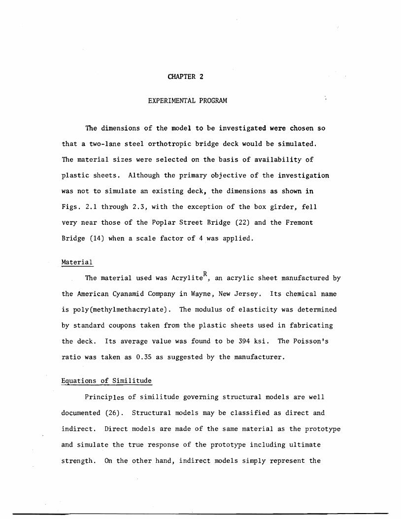
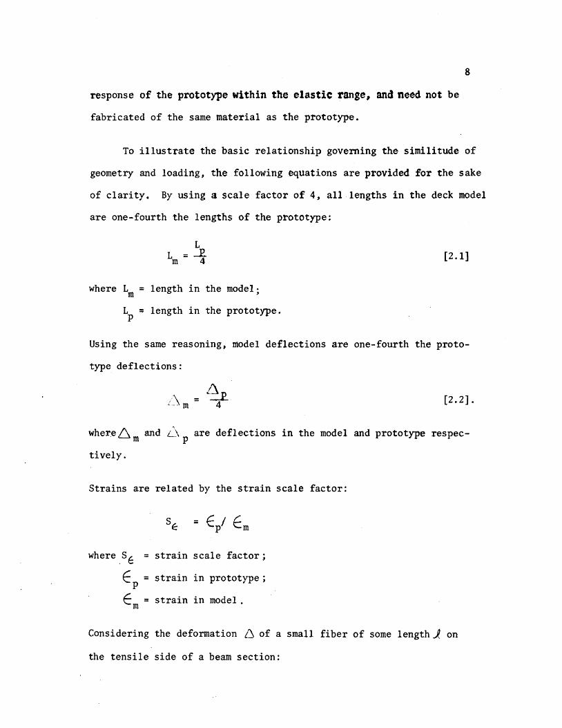
9
[23]6 p = ~ Jp
6 m = fm 1m [24
By substituting Eqs pound21] and [22] into [24]
L ~= [2 S]tm --t4
The substitution of Eq [23] into Eq [25] gives
[26]ip = ~
Therefore the strain scale factor equals one in a true model where
strains at corresponding points in model and prototype are equal
provided the loads are scaled properly
~
Since SE = ~ = 1 loads can be scaled using the following relationshy
ships
p = 6 AP P P
~ =~ and m E m
A EA = m (4) 2
where A and A = areas of the model and prototype respectivelym p
E and E = the modulus of elasticity of model and prototype m p respectively
6 and 6 = the stress in the model and prototype respectivelym p
P = load on the prototyPep
10
From which
[27]Pp = [CAm)4J [Om ~J Since P = (5 A m mm
P E S =-E = (4)2 -pound [28]p P E m m
where S = load scale factorp
P = load on the model m
If the modulus of elasticity of steel is 29000 ksi and that of plastic
is 394 ksi then
P P = -Es = (0000849)P [29]m pp
This means that a load of 100 lbs used in the model test is equivashy
lent to a 1178 k load on the prototype The total weight of one H520
truck is 72 k (Fig 24) (1)
Loading
Scale models of actual trucks would require a minimum length of
7 ft on the deck Because the length of model deck was only 12 ft it
was considered sufficient to simulate only single whe~l and axle loads
The size of t~e loading pad was taken as 6 in by 25 in which is
equivalent to an AASHO HS20 truck wheel contact area (Figs 25 26
and 27) This area is determined assuming that the tire is in direct
11
contact with the deck plate without considering pavement thus represhy
senting the worst condition for local stresses in the vicinity of the
loaded area The applied load was transmitted to the deck through a
l2-in neoprene pad and a steel plate as shown in Fig2S A summary
of all loading positions is shown in Fig 29
Strain and Deflection Gauges
The strain gauges used were Micro-Measurements Inc EA-06-2S0BGshy
120 which are general purpose gauges intended for static and dynamic
stress analysis To overcome the heating problem and the resulting
errors caused by the poor heat sink quality of plastic a method of
pulsing which will be discussed subsequently under testing procedure
was used
The positions of the strain and deflection gauges are shown in
Figs 210 and 211 respectively The gauge installation procedure
as suggested by the manufacturer was followed closely After installashy
tion a piece of cellophane tape was placed over each gauge to protect
the lead wires All lead wires were cut at equal lengths (12 ft) to
ensure that variable lead resistance would not be a factor during
testing The strain gauges were monitored by a Datran II strain recordshy
ing system which consists of a Model 1330 lO-channel scanner a Model
321 strain indicator and a Franklin 1200 Hi-Speed Printer (Fig 212)
A gauge factor of 210 was used for all strain gauges
Deflections of the deck were measured with dial gauges to an
accuracy of 0001 inch The gauges were mounted on a bridge supported
12
on two sides by metal stands (Fig 213) Support deflections also
were monitored and used later to obtain corrected span deflections
Testing Procedure
In testing ~odels madamp of plastic two problems are encountered
which are not significant in metal modelS (a) As mentioned earlier
the temperature of the strain gauges increases due to the insulating
characteristics of the plastic (b) A significant amount of creep occurs
To avoid heating strain gauges weteonly activated during an
actual reading In this manner the presence of current in each circuit
was limited to just a fraction of a second To efficiently take the
readings the Franklin 1200 Hi-Speed Digital Printer was connected to
the strain indicator thereby enabling all ten channels to be read and
recorded within one second
In tests conducted on independent specimens it was found that
significant creep occurred immediately after the application of a load
These tests also showed that after approximately five minutes 95 percent
of the creep had taken place therefore it was decided to take all
readings after a five-minute pause a procedure followed in determining
the value of the modulus of elasticity The testing procedure was
as follows
1 Take initial strain and deflection gauge readings
2 Start timer
3 Apply weights
4 Take immediate readings
13
5 Wait five minutes
6 Take readings
7 Apply next loading increment and repeat cycle until
five increments at 20 pounds each have been added
By using 20-pound increments a total of one hour was necessary to
complete one test as the deck was unloaded the same way Figure 212
shows the complete set-up during one of the tests One person took all
dial gauge readings which were called out to a recorder to reduce the
chance of error
CHAPTER 3
FABRICATION
The orthotropic deck model was built of standard ll6-in and
lIB-in thick sheets of acrylic A laboratory check of these thickshy
nesses revealed that the 116-in sheets were 0061 in thick This
value was used in determining the section properties of the deck model
All connections were made by a gluing process thus simulating welds
in an actual steel deck Prior to fabrication of the model test beams
were built using proposed gluing techniques These beams were subjected
to heavy loadings which verified the adequacy of the welds Due to the
unavailability of desired lengths of material splices were required
Splices
The deck plate required a l2-ft x 6-ft sheet of liB-in acrylic
but the largest size available locally was 10 ft x 6 ft Therefore
a splice two feet from the end of the deck was considered Because the
10-ft x 6-ft sheet was 6 in oversized the splice actually occurred
lB in from the end midway between the last two floor beams This was
considered acceptable as the splice was 3 ft from the points being monishy
tored and in an area where the stresses were low
In order to provide continuous ribs a l2-ft length of 1l6-in
material was needed Again the maximum length that could be purchased
locally was 6 ft Under the circumstances it was determined that a
center splice in the ribs would be acceptable as the deck plate is
15
continuous over the rib splices The tie girder splices were made 18 in
from either end and staggered so that no two splices would coincide
All splices were made butt-joint style When a good fit was
obtained dichloromethane was used as a bonding agent where there were
inconsistencies in the fit PS-30 was used
Gluing Techniques
Dichloromethane a capillary action solvent that produces a medium
strength joint can be used only when parts are closely fitted with
no visible gaps The solvent is applied with a hypodermic needle along
the edge of the joint Capillary action draws the solvent between the
parts softening and swelling the plastic which then permits actual
cohesion of the parts After approximately five minutes the solvent
evaporates leaving a hard J clear joint It was found that a thickened
solvent could be produced by dissolving 3 percent clean plastic chips
in the dichloromethane This more viscous solvent had bonding charactershy
istics similar to the unthickened solvent but was more manageable when
applying
PS-30 a highly viscous polymerizable cement has little or no
solvent action and produces good joint strength after four hours
PS-30 comes in two components A and B Component A is a viscous solushy
tion consisting of a monomer and a polymer while component B is the
catalyst The shelf life of both components is six months the pot
life is only 25 minutes Before mixing the components should be
16
allowed to warm to room temperature for 12 to 24 hours Proportions
required to make PS 30 are
Component A 9S grams or 9S cc Component B S grams or S cc
After stirring for two minutes the mixture was applied to the joint
with a 13 gauge needle and 30 cc syringe
Although it is recommended that a V-type joint be used in conjuncshy
tion with PS-30 for maximum strength because of the small thickness of
the parts no V-grooved joints were used during fabrication PS30
was used only to overcome natural nonconformities in fit
Cutting
The plastic sheets were cut to size by a 10-in radial arm saw or
a l2-in table saw with a No 88 plywood blade To avoid handling the
deck plate it was trimmed to size in place using a 7-in Skillsaw with
a plywood blade
The l-12-in strips used for the rib bottoms were cut on the
radial arm saw (Fig 31) Out of 24 strips cut four were determined
to be unsuitable for use and had to be cut again due to a variance in
width For cutting the 3-in rib webs the blade was set at a 14 degree
angle providing the beveled edge needed for a proper fit to the rib
bottoms and the deck plate (Fig 22) Of the first six strips cut this
way three had to be discarded as they were as much as 14 in out of
alignment At this point it was decided to use the l2-in table saw
to ensure a better edge alignment
17
A total of 44 rib sides and 22 rib bottoms were cut To assure
that the ribs would be 12 ft in length when glued together two sides
and one bottom were bundled taped and then measured and trimmed off
in 6-ft lengths with the radial arm saw
Ribs
In order to hold the rib sides at a 14 degree angle while gluing
to the bottoms an eight-foot gluing jig was constructed to adequately
accommodate the 6-ft rib lengths (Fig 32) Foam rubber 12 in thick
by 1-12 in wide was laid on the bottom of the jig to provide a spring-
like effect so that the rib bottom plate would conform to the rib webs
during the gluing process The following step-by-step process was used
in the fabrication of trapezoidal ribs
1 Lay I-l2-in plastic strip on foam rubber pad
2 Place a I-in by l2-in wood strip on top of the plastic
strip
3 Compress foam pad and clamp in place using large C
clamps (Fig 32)
4 Place rib webs along the two edges of the wooden jig on
the rib bottom plate
5 Using small C clamps fasten rib sides to sides of gl~ing
form (Fig 32)
6 Release large C clamps allowing foam rubber pad to gently
push the rib bottom against the rib webs making a firm
contact
18
1 Apply dithloromethane to inside edge of rib using a hyposhy
dermic needle (Fig 33)
8 Wait 30 minutes then release small C c~amps and remove
finished rib from jig
9 Inspect rib for any opening along line and if necessary
reseal with PS-30
Floor Beams
Fabrication of the floor beams consisted of four steps
1 Cutting 8-in by 6-ft strips for web plates
2 Cutting openings in the web plates as shown in Fig 34
to accommodate the continuous ribs
3 Cutting five lIS-in x 2-l2-in by6-ft flange plates
4 Gluing flanges to the web
Some problems were encountered in making the web openings for the
floor beams The sides of the 3-in deep openings were cut with a radial
arm saw while the 1-12 in bottom was cut with a coping saw The same
technique as in gluing the ribs was used to glue the web to the flange
The flange was placed on a foam rubber pad and a series of clamps were
used to form a jig to keep the web upright (Fig 35) Small wedges were
then slipped under the foam pad where needed to provide the proper fit
Gluing was accomplished by applying dichloromethane to both sides of the
web No PS-30 was needed
Assembly of the Orthotropic Deck Model
After the fabrication of all the basic elements of the orthotropic
19
deck model was completed it was extremely important to follow a well shy
planned sequence of assembly steps The protective paper was first
removed from the deck plate and the ribs were placed on the deck in
their proper positions To provide a means of pushing the deck plate up
against the ribs a large foam rubber pad was placed under the deck (Fig
36) The ribs were positioned by using the notched floor beams as
spacers When all ribs were in their proper position weights were
applied at various locations to provide a tight fit Again wedges were
slipped under the pad to help make the deck conform to the ribs All
ribs were checked visually and with a thin feeler gauge for proper connecshy
tion to the deck The ribs were kept tight against the floor beam
notches by means of thin wooden wedges which were manipulated by a 7-ft
pole with a hook on the end
Pursuant a lengthy process of assuring that every piece was
properly positioned and fitted ribs were glued to the deck using
dichloromethane This assembly was left undisturbed for 24 hours after
gluing before removing weights and floor beams Checks were made for
places that were not welded properly and such points were reglued
using PS-30 After the rib plates were spliced at mid span the floor
beams were repositioned over the ribs More filing of floor beam webs
was needed in order to obtain a Eroper fit In the event of some gaps
(116plusmn in) which were too large to bond with PS-30 J small plastic
wedges were inserted prior to gluing In order to keep the highly
viscous PS-30 from pushing the wedges out during application dichloroshy
methane was used to spot-weld the wedges in place before applying PS-30
20
The floor beams were held in place during the welding process by
heavy steel bars lying over the tops of the ribs and clamped to supports
at each end (Fig 37) Weights were placed on top of the beam flange
to help hold it against the ribs The floor beam was then welded to the
ribs and deck plate After all floor beams were in place the deck was
turned over to check the reliability of the welding (Fig 38)
When it was determined that the welding of basic deck elements was
adequate the model was again turned over and the tie girders were added
The inside web of the tie girder was welded to the deck and floor beams
first The outside web was then installed followed by centering the
flange and welding with dichloromethane The total weight of the
finished assembly was approximately 125 pounds
Supports and Loading Beam
The model deck was simply supported on four corners by 2-in by
3-in steel plates (Fig 21) Two of these plates were placed on fixed
rollers (simulating a pinned joint) while the opposite pair was placed on
standard rollers
The loading beam consisted of a 10-ft aluminum H-shape supported
at loading point or points Two weight hangers were provided on each
end of the loading beam Each calibrated weight consisted of a fiveshy
pound chunk of caulking lead During testing a number of weights were
hung from the loading beam to obtain the desired load (Fig 39)
CHAPTER 4
TEST RESULTS
The Computer Model
A discrete element model capable of handing orthotropic plate
problems (18) was used for the analytical part of this investigation
The model (Fig 41) represents the stiffness geometry and support
conditions of an orthotropic plate continuous over flexible floor
beams The -principal features of this method include the representashy
tion of structural members by a physical model of bars an~ springs
which for analysis are grouped into two orthogonal systems of beams
and replacing the differential equations for orthotropic plates by
their finite-difference equivalent The problem then is reduced to
solving a large number of simultaneous equations rather than one complex
differential equation The computer program developed from the above
model permits the stiffness properties of the orthotropic deck and
floor beams to be included on an individual basis -thus resulting in
a more realistic representation of the bridge deck as an equivalent
orthotropic plate The bending stiffness of the plate in the x- and
y-directions and the Poissons ratio effects are represented by elastic
blocks at the nodal points (Fig 42) Support conditions are simushy
lated by elastic springs of appropriate stiffness at each joint while
twisting stiffness is modeled by torsion bars connected to the rigid
bars between elastic nodal blocks
22
Member stiffness and load values are entered in the ~omputer
program by first dividing the slab into increment widths of hand h x y
in the xmiddot and y-directions respectively Figure 43 shows the coordishy
nates of the deck model under investigation A joint is defined as
the intersection of the station lines in each x- and y-direction while
a mesh is understood to be the area surrounded by four jOints Or~hog-
onal flexural stiffnesses D and D are entered on a per unit width x Y
basis The torsional stiffness H is input on a unit width basis for
each mesh its value is determined with the aid of a separate computer
program following the method in reference (2) A listing of this proshy
gram is provided in Appendix ICa) Applied loads are assumed concenshy
trated at each joint therefore a distributed load must be proportioned
among the surrounding joints on a tributary area basis Unyielding
upports are simulated by introducing very stiff springs (500 kin)
at the joints on the support station line Discrete members such
as floor beams and girders can be entered on an individual basis by
giving their total stiffness values A typical computer output is
given in Appendix I(b)
Idealized Sections
The only function of the tie girders was to provide a flexible
support for the floor beams Therefore no attempt was made to properly
scale the tie girders~ as in an actual bridge their span lengths and
cross-sectional dimensions would be much greater ConsequentlYI
theoretical investigations by Chwalla (5) on determining th~ effective
23
width of the deck acting as the top flange of the tie girder could not
be used Instead this effective width was determined experimentally
by measuring girder deflections for several symmetrical loading condishy
tions and computing the required inertia needed to obtain this deflection
The tie girder inertia value was found to be 4434 in4 which corresshy
ponds to an effective deck width of 20 inches
The effective widths of the orthotropic deck plate acting with
a rib and floor beam were computed using the method outlined in the
AISC Design Manual (2) and others (23) It was determined that because
of its narrow width the tie girder would offer little or no rotational
restraint for the floor beams this justified using the full length of
the floor beam as its effective span when computing the effective
width All idealized sections along with corresponding inertia and
stiffness values are shown in Appendix II
Calculated vs Observed Deflections and Strains
(a) Deflections All deflections were corrected to account for
support movements during loading This was done by using a linear
interpolation of the settlements between supports Although a biaxial
stress field exists in the rib plates the use of uniaxial strain
gauges to determine strains at rib bottoms was justified through
experimental observations made by Erzurumlu and Toprac (9) Linearity
checks were made on deflections and strains for all loading conditions
prior to plotting any profiles
computed and measured center floor beam deflections are shown
in Figs 44 through 49 for all loading conditions At this juncture
24
it should be noted that the mathematical model does not account for
shear deformations The deflection due to s~ear was computed for a
lOO-lb load applied at the center of the floor beam and was found to
be 0023 inches If this correction is applied to the computed deflecshy
tions of Fig 44 the correlation between computed and measured
deflections would be very good with the difference reduced to less than
one percent Examination of floor beam deflection curves for other
loading conditions indicates that when the load is not directly over
the floor beam there is closer agreement between computed and measured
values This substantiates the need for a shear deflection correction
on floor bearns as less shear correction would be needed for smaller
floor beam loads It is interesting to note that good agreement exists
between computed and measured deflections at the tie girder as long as
the load is symmetrically located however as Figs 48 and 49 indishy
date a difference of approximately five percent exists when loads are
positioned in the driving lanes Thus the tie girder inertia value
and corresponding effective deck width are dependent among other things
upon the position of the load which is what Chwallas (5) theoretical
investigations indicated
Good agreement exists between experimental and computed deflecshy
tions of the ribs in Section 1-1 (see Fig 211) for the loading condishy
tions shown in Figs 410 through 417 Generally measured deflections
are slightly more than those computed with the difference seldom
exceeding five percent Again shear deflections may account for
25
some of this discrepancy as the difference is usually greater in the
center of the deck or directly under the loading pads Another possishy
ble cause of discrepancy is the localized distortion effect in a rib
produced by the moving together of the deck plate and the bottom rib
flange resultingmiddot in a lowered moment of inertia and section modulus
when a rib is under load In Fig 411 the computed deflection
directly under the load is greater than the measured deflection This
behavior is believed to be caused by the fact that the wheel load is
input as a point load due to the limitation of the mesh size Because
the 6-in long loading pad is centered over a node it cannot theoretishy
cally affect adjoining nodes In actual behavior however the load
is distributed to some extent to the adjoing nodes thus accounting
for the difference between measured and computed deflections on the
adjoining ribs An examination of Fig 417 reveals the same type of
loading condition resulting in the same relationship between computed
and measured deflections The extent of the discrepancy is not great
in this case as the load on each node is only one-half that of Fig
411 Generally when the load is over the floor beam the rib action
is fairly uniform (Figs 410 413 415 and 416) When the load
is in an adjoining panel centered between floor beams (Fig 412)
there is a slight rise in the center rib The decreased magnitude
of the computed deflection again is due to the load being input as a
point load A check of the strains at this point both theoretical
and measured reveals that the bottom fiber of the loaded rib is in
compression In contrast the adjoining rib bottoms are in tension
26
and thus verify the shape of the curve The deflections and strains
for computer coordinate (66) (floor beam bottom) are given in Table I~
Deflections again vary depending on the position of the load with the
greater percentage difference being when the load is near the floor
beam
(b) Strains Overall strains vary anywhere from 1 to 49 percent
with computed values generally higher than measured values The large
discrepancy between computed and measured strains is probably due to
the following causes
1 Instrumentation error
2 Warping of the deck due to uneven support settlements
3 Idealization of the structure as a discrete element
model
4 In the case of ribs the assumption of a uniaxial
stress field in the rib bottoms
The instrumentation error could be as high as ~20 ~inin
and would account for a larger percent difference between computed and
measured values in low ranges Therefore readings less than lOO~inin
would be too small to verify the adequacy of the discrete element comshy
puter pr~gram
The warping effect could also cause plus or minus strain errors
depending o~ the magnitude andlocation of the sUPPQrt s~ttleIlJ~nt$
27
A safe assumption is that the more warping the greater discrepancy
between computed and measured strains As an illustration referring
to Table I the 30 percent difference in loading condition F could
be due to warping because of the unsymmetrical loading in that case
An examination of the support deflections reveals that Gauge No 7
drops 0049 in while the diagonal corner Gauge No 9 drops only 0011
inches This indicates a warping effect and a possible explanation of
the 30 percent discrepancy
While the accuracy of the discrete element model could be
improved by using a finer grid the mesh size chosen was considered
adequate for the purpose of this investigation and prevented excessive
use of computer time Because the theoretical data generated for
deflections and bending moments are average values there will likely
be some differences between experimental and computed values The
errors introduced by assuming a uniaxial stress field in the rib
bottoms would have some influence on the computed versus measured
relationship which would be more apparent when the ribs are heavily
loaded
Computed and measured strains for most loading conditions are
given in Tables II through IX Keeping in mind the previously
mentioned possile sources of error there is generally a good agreeshy
ment bet~een theory and test results It is interesting to note that
when a load is directly over a rib (Tables III and VIII) the computed
strain is considerably greater than measured strain--38 to 49 percent bull ~ ~
28
This can be partly attributed to the load being input as a concentrated
load and partly to the excessive distortions of the rib plate directly
under the load This localized distortion effect was also noted in the
investigation reported in Reference (9) A check of the floor beam
strains near the girder (Table II) Gauge 1-7 indicates there is tension
present at that location Although the strains are too small to be conshy
clusive it indicates the assumption made earlier which stated that
the tie girder offered little or no rotation restraint for the floor
beam was reasonable
It could be concluded that within the limits of the experishy
mental program the orthotropic deck responds as predicted by a discrete
element computer program in the elastic range
1
CHAPTER 5
CONCLUSIONS AND RECOMMENDATIONS
Conclusions
In view of the findings documented in Chapter 4 it may be conclushy
ded that
1 Plastic sheets of acrylic can be used as a modeling material
for the fabrication of orthotropic deck models Ordinary
woodworking tools are effectively used in the deck construcshy
tion thus keeping costs to a minimum
2 Dichloromethane and PS-30 are compatible an~ effectively
simulate welds in steel orthotropic decks when tests are
conducted within the loading range of this investigation
3 Creep effects of plastic do not adversely influence test
results when proper testing procedures are used
4 Indirect models can be constructed from plastic acrylic
material to test structures as complex as orthotropic decks
5 The discrete~element model proposed by Matlock and Panak (18)
is effective in predicting the moments and deflections
along grid lines of multiple panels of orthotropic decks on
flexible supports
30
Recommendations
Future investigations involving orthotropie bridge decks should l
based on this study be concerned with the following
1 A computer program using a finer mesh size should be run
on this model to see if the results would change signifi shy
cantly
2 The deck should be supported on concrete blocks so that
warping would not be a factor in recorded deflections and
strains
3 The box girders should be properly scaled so that a check
on its torsion restraint could be made
4 The model should be extended to a length such that a full
AASHO Highway vehicle could be simulated as a live load
5 Investigations should be conducted on the interaction of
the rib and floor beam by extensively gauging the areas of
intersection
6 Decks using different types of ribs (open biserrated etc)
should be modeled and their response compared with those
obtained from closed rib models
7 Orthotropic decks on flexible supports should be modeled
with steel as a means of checking the ultimate strength of
the system
REFERENCES
1 American Association of State Highway Officials Standard Specifications for Highway Bridges 1965 Washington DC
2 American Insitute of Steel Construction Design Manual for Orthotropic Steel Deck Bridges New York 1963
3 Boussinesq J V Complements ~ une Etude sur la Th~orie de lEquilibre et du Mouvement des Solides Elastique dont Certaines Dimensions Sont Tres Petites par rapporta LAutre Journal de Mathematique Paris 1879
4 Cauchy A L De la Pression dans un System de Points Materiels Exercices de Mathematique Paris 1928
5 Chwalla E Die Formeln zur Berechnung der vollmittragenden Breitediinner Gurt und Rippenplatten Der Stahlbau No 10
1936
6 Cornelius W Die Berechnung der ebener Flachentrag-Werke mit Hilfe der Theorie der orthogonal-anisotropen Platten Der Stahlbau Vol 21 1952
7 Engineering News-Record Californias Orthotropic Bridge Set to Go October 29 1964
8 Engineering News-Record The San Mateo-Hayward Bridge A Fabrishycation Dream June 23 1966
9 Erzurumlu H and 1oprac A A Research on the Deck Elements of the Ammi System Structures Fatigue Research Laboratory Report No P550-12 The University of Texas Austin March 1970
10 Geckeler J W Elastizitatstheorie anisotroper Korper Handbuck der Physik Band VI Berlin 1928
11 Gehring R De Aequationibus Differentialibus Quihus Aequilihrium et Motus Laminae Crystallinae Definitur Berlin 1860
12 Guyon Y Calcul des Ponts Larges ~ Poutres Multiples Solidaris~es par des Entretoises Annales des Ponts et Chaussees No V Septembre-October 1946
13 Hardenherg G J Design of the Superstructure of the Port Mann Bridge1f The Engineering Journal July 1961
14 Hedefine A and Silano L GI Design of the Fremont Bridge ASCE National Structural Engineering Meeting Portland
32
15 Heins C P and Hails R L Behavior of Stiffened Curved Plate Model Journal of the Structural Division Proceedings of the American Society of Civil Engineers Vol 95 No ST-l1 November 1969
16 Huber M T HDie Grundlagen einer rationellen Berechnung der kreuzweise bewehrten Eisenbetonplatten Zeitschrift des Osterreichischen Ingenieur - und Architekten-Vereines Vol 66 No 30 1914
17 Massonnet Ch Methode de Cal cuI des Ponts a Poutres Multiples Tenant Compte de leur Resistance ~ la Torsion Publicashytions International Association for Bridge and Structural Engineering Vol 10 1950
18 Matlock H and Panak J J A Discrete Element Method of Analysis for Orthogonal Slab and Grid Bridge Floor Systems Center for Highway Research Report No 56-25 The University of Texas Austin May 1972
19 Mayer R Die Kurpfalzbrucke uber den Neckar in Mannheimtt Der Stahlbau Nos 6 7 8 1952
20 Naruoka M Okabe T and Hori K An Experimental Study on Model Continuous Beam Bridge with Steel Deck Publications of International Association for Bridge and Structural Engineering Vol 18 1958
21 Pelikan W and Esslinger M Die Stahlfahrbahn-Berechnung and Konstruktion MAN Forschungsheft No7 1957
22 Shields E J Poplar Street Bridge Design and Fabrication Civil Engineering February 1966
23 Troitsky HS Orthotropic Bridges Theory and Design The James F Lincoln Arc Welding Foundation August 1967
24 Troitsky M S and Azad AK Bending and Torsion in Orthoshytropic Deck Box Girder Journal of the Structural Division Proceedings of the American Society of Civil Engineers Vol 98 No ST-9 September 1972
25 Voigt W Lehrbuch der Kristallphysik Leipzig 1910
26 White Richard N Similitude Requirements for Structural Models Conference Preprint No 469 ASCE National Meeting on Structural Engineering Seattle Washington May 1967
-
P
- () ~ -4 X ) -- tQ - 0 -I ftl
rshy ~ r 1gt
-1
C It (
~
~
shyo
Z g
- c o-Z
Ie
CP C
---
-
-n-G ~
0 1tI lt
0
t IfI Z J ()
Z P
I I
I I
I
I I
I i
I
-tshy I I t I ~
I I I I I
~
t ~
I r-shy
1-shy I I I I I I I I I I
I I I I
I I I
-
I
I I I
I I I
I I
Imiddot
-
bull shy0
--tshyI
I po U
Q r---shy 0
I i
~ 0
I
)0
~ omiddot-0 ~ T bull l
l
~LO II
OOlte
middotOOmiddot~middotmiddot---I
GLQ ~olt -rL1
OO~ 00laquo
gt o obull
tf
CNOIN~HIO
0 ~~HM 9middot21middotCJ1~ bullPti Z
JJd 1fO 1nJS 4MJ ~Q dOl H1 14
1 QJO01 d11t19ff
bullIampZ Ie I~ J~fianlt ~11aM flU iD dol 4tU J ~41~ JatlN~
(l~t1n4Ci( -amiddotl1f14 oN1
01 l7Z til
OJ oz z
01 Oll 9
CHWI
L$ C~HN
~ tdl Nt
dVO ~aHM
1g=3HM NaJ t11 -10 4-a~ l 11NO lt middot21middot)~ I
~JJM irtJ ~del erialJ 4211 J ~oJo ~1J
lfLNO ~1(11l1
~=3a1 IN=lfn~J ClJ10 llJltCnlt i3U (1110C odo 11 11lo~
OZltH --ao~ ~~IC d ~NIO~O 1z middot~Id
fa tt a oe 01 ---~l
Z~
01
~Yiq~~ ~a~rAJJlta
~ta ~o J~ ~fd ~
1 ~shy ()
~ 0 Id
lj~t43001~ N~~Ml~Q t+1r+1ML=aca ltofd d
CI 0
H1aq ~OG1-l -10 ~ clta Ia If CO vd ~
1 0
------
N k I
C () n -till J
~-9ca (1001 d) lY bull ltltlIa N~~Mll ltQ~d -
I~ raquo ~
1 ---1-- 0 f 111
)~
c ~aq 2I001-i N~~Ml Haca 7J001d -~Cd ~ C317J 11 ta~d -(f) -io bull ~I2J LV 011d bull
I 1)1 ---shy-PJ----4---+ 0
Q 9
AI
~-lf11 l J
--shy-~---t----- -
j~
0- lIf
--
-~ o
I Imiddot I I I I
I
I I sa I
bull- bull
tEl - - l=~ Abull -C)
bull ~
I II
I I I
I ta I ~ ~~ lar I j Il~ CP e 0
tIbull
~bull ~ -shy
[l ~ 1-1 -T
bull --1 bull bull bull -~ Jl 1 bull -abull ~ I I I I
~I I JQ
Ql I I I I ~ tf of(
Jl ~
tclXll~~4 1IDD~ _ I - r-
if bull(Jill i I
I
I I
I I
II
I
ot
---
-
II
G ~
-
r 0 ~ tgt
0 ~
Z
~
0 tgt r
G 1gt C lti
I I I I
I I
I I I I
I I I
I 1
-- _shy - - I
I I t
t I
I I I
I I I
1 I
o~ P~ t (~ lt1gt1= c~ bull bull Q )l ~ ~ -
i I
I shy
I I I I I
bull bull oa I
~
1Q I I I i 0 I I I I I - I-4
~
I
~amp~faq 2Joo -I -shy -I r J --1-shy I I I
I I I II
I
_L
ED CD agt
)02z[
lQ ()-C0 ~UQ
)
0 ~ It )10 U
-1-
U t J
t -0 0
42
Fig 212 Test Set-Up During Testing
Fig 213 Bridge Used in Deflection Measurements
43
Fig 3 1 Radial Arm Saw Used fo r Cutting Plastic Sheets
Fig 3 2 Gluing Jig and Clamps
44
I
Fig 33 Application of Dichloromethane to Rib Seams
Fig 34 Cutting Openings in Web Plates
45
Fig 35 Jig Used in Gluing Floor Beam Web to Flange
bull Fig 36 Deck Assembly Prior to Gluing
46
Fig 37 Ass emb ly Us ed to Hol d Floor Beam In Place Prior to Gl uing
Fig 38 Turning the Deck Over
( gJ ) 1=3COH JN~r~1-=3 1~-iZJca HOCl-i LNIOr 11dkl z-v middot91j
( qy) ~L~1d I d0211oHJ2IO -10 1aOH LN3H31~ JJ~ZJC(j -tJl-i
x~~~____________~
2
-r
middotat
x 2~ 1 01 ( ~a ~ C lt~ ~I 0 --u
-~ ~
~~ ~ f) middot)(4
D b-
~o
~4 t IU
1)1 G
J
-n I~flt)(~L1J) middotPN ~9H-(i ~
~ I -1 rT nn rrrr1 TTlVf- d)
bull ~ d~Or lID IIU IIJJ LUJ
)Y 0 (01 q ~V C1JC101
0
() shya r --hTIm I 1111 I~
l~ ~ I1II
D -0 -aN 00~O1 ~ tJ4 o~a ~o - c - -I P
ct 10 -~ lti -shy IQ
1
-) ----- _bull -tt -shy-t
-(p
0
~ 0
I)
-~ ~
~ P
~ ~ 61
0
~
~ ampgt p ~ tt Z 4 m ft
r () 0 F
0 ~ 1gt - ~
w r n ( -4-~ 7shy
r 0 Cgt 0bull ~ ()
7 C 0
bull () G to a
C -I Il 0
0
0 tI
r
0-
0 0-
- Q 0 I
0 I ~
0 0 00
I Z z ( r tT ~ lti
~ ~
- 0
( -l -I t -a 7 ( -4
11 r l1
r ()
~C ~---- ~ ~ shy ~ - 0 8~ ~ tIshy -
bullbull 0 1 0 0 lt) 0 r 1t ~ r (
t - -()
L
) P P ~ C)
Z P Jgto
0
p
~ 1 Qshy
~ s
l Z -4 n f)
r l 0 1
G ro P 1_ Q t( l r ttl ( -- ) Z
r (l 1gt
~ ( () Z 0 Q
() 0 0
()
i I
-
~~ -1)
-~
-~
~~ -
-~ ~
-a
-() II
()
U ~
-~ f(0 1gtshyt(J ~~ e w ~o 0
() C)
~ () -()
i I
9 ~
~
~ t1 L --I rt ll
r -
C) 0 1
~ w I_ 0 t
r w (
-- - -Q
Z
r ~ 1gt Q ~ 7 ~
~
1 r IT (
--
o~ I -z ( I It
~
~
~
~ -~
() shy
~ N l 0 () ~ U
LS
G - ~ 1
rshy)
~
$ 1gt
r shyo l -r r f(1
--l )
7
-
0 It 1 r It t - 0 ~ ~
-Z 0
~ I 0 O~ z I (
~ -~ ---] m ~
N ~
ii ~ 0 -ltP shy ()
IT 1 ~
t
)
~
~ -~
lt)
I
shy Gmiddot ~
-
r (J
It
Qrshy-~ t) l ~ ll () () 1
W bulli
rQ
1gtshyi
w~ r ft ( -t - 0 7shy
r ) 1gt ~ middot ) ~ Z
middot ~
n
- 9
-~ -J IT ~ --shy0 Z II-shy
~ n r
-4 )
z N Ol - fl 0
rshy r ~ Igt 0 ~ Z ~ l
~ Sl-() 0
~~ Ot i i
I shy~ a (l
~ 1)( c~ ((
wo u
0 fT shy
t) t) IT 0
~ 8~ 0 -l
(5 I ----I I Z C Z ( I (T
~ ~ ~ 0 ~
I J~ t1 (( --lshyshy( () 1gtshyZ ~ bull
U It
rshy bulltI shy-II =Jesshy ( --
l -I 0 z 8shy 0shy
fl ~
l (
0
rshy(l
r t) 1gt ~ bull ~
z ~
~ Jgtoo
~
~ o I
~ ~
-)l J
~ ~ 0 z
-I
0 tr -p r 11
n Q Z ~shy P ~ ta 0 1- r - r ~ 1gt ~ ( Q1 ~
(~ 0
t -0 C 0
0 fJ
rshy rn (
-~ ~ ~ -I 0 o 0 0 o bull ~ 8~ I I bull i I Z
--
1--shyZ ( I
-~ en ~ ~ ~
1 ~ -J ( -
0 z --
~C-~~O - f1I -~TI ~r
0II (
--- 0 ~ 0 ~l~ Z 0 1
1Q
Ibull
-~~~ I -~~ _1G -() 0
~o S
rshy f1
r C) 1gt 0 ( 0 Z -0
0
--s U C ~ 11 0
9
-l ( ~
-4shyt) z bull
- 0 n
rshy (t1
--l t) Z lQ
-0 -a fQ () r
r 0 ~
~ ( () Z ~
sgt
0 IT -n r IT ( -l
0 Z Z ( -t ff J
6 -I bull ~ S
N
0 0 ii ~
S) p ~ ~ ~ -0 0 6
8 o ~ 0 i I i I
~ ~ -~ U ft C
shy0 z -- - - Cl1
- r~ - lr-
-~ ( 11 0 1gt
to ) -0 C C f3 -t t Cl1 ~ 0
t~ shy 0 ()0 z
r
r ) 1gt ~ f ~ 7shy9 0
~ -J
t
(p ~
0
C
() 0 ~ 08~ o~
i
~ ~ -J shyl 11 ( -t 0 Z bull-~ rshy Il t ~ --- --I-~
() 7shy
N tl 0 P
Q lQ ~ ~ lt)
r ~
r Il (1 WI
r r 0 0 1gt tgt 0 ~ ( ( tgt a Z z 0 0
t ttl
I ~
1 (
o I
~ c ~ 1Q
ltV 0 Q
- ltY-o o 0 I
C
TABL
E I
FLOO
R BE
AM D
EFLE
CTIO
NS
FOR
GAUG
E LO
CATI
ON
1-5
FL
OOR
BEAM
STR
AIN
RE
ADIN
GS
FOR
GAUG
E LO
CATI
ON
1-9
LOAD
iNG
CON
DIT
ION
r
A
B
C
D
E
F
-
Com
po
Mea
s
Com
po
Mea
s
Com
po
Mea
s
Com
po
Mea
s
Com
po
Mea
s
Com
po
Mea
s
Def
lect
ion
(1
-5)
Inch
es
011
4 0
124
013
5 0
151
011
3 0
124
013
2 0
145
011
0 0
116
013
0 o
~42
Com
pute
d M
easu
red
091
0
89
0
91
091
0
95
09
2
iStr
ain
(I
-9)
Mic
roin
ches
17
5 20
6 61
8 53
1 15
7 17
3 44
6 38
0 12
2 13
7 33
8 26
0
Com
pute
d M
easu
red
-shy~-
085
1
16
----_
__
_
__
shy_
_shy
087
1
17
-_
shy
089
ff
13
0
P =
100
LBS
til
--
J
58
TABLE II
STRAIN READINGS FOR LOADING CONDITION A (1
I
~ (1)
cQ
~ 0 0
~
~ (1) +-gts (1) u
GAUGE NUMBER Computed u in in
Measured AI in in
ComEuted Measured
I-I 873 789 111
1-2 679 660 103
1-3 510 495 103
1-4 361 329 110
1-5 229 202 1 13
1-6 - 1-7 -
-- en
Jl 0 - bull
s 0 +-gt u (1)
til
11 3 205 208 099
11-6 202 229 088
11-8 194 199 097
11-9 183 173
-106
11-10 170 147 116
- -g g instruments
P 100 LBS
ji
I
59
TABLE III
STRAIN READINGS LOADING CONDITION B lt
~ (J)
Ql
~ 0 0 ~
~ (J) ~
53 u
Computed Measured Computed GAUGE NUMBER u inin JIJ inin Measured
I-I 599 599 107
~
1-2 486 495 098
shy
1-3 375 379 099
1-4 272 251 108
1-5 176 156 113
1-6 -
1-7 -
r- en
0
r-I ~ -
I
sect r-I ~ U (J)
U)
-11-3 2429 1635 148
11-6 453 593 076
11-8 238 242 098
11-9 202 174 116
11-10 -
Too small and within the range of tolerance of record1ng instruments
Wheel directly over rib P = 100 LBS
60
TABLE IV
STRAIN READINGS FOR LOADING CONDITION C 11
Computed Measured ComEuted GAUGE NUMBER ~ in in AJ inin Measured
I-I 587 500 117
1-2 601 559 108 I
i
I
~ 4)
CQ
ft 0 0 -c u ft G) +J
5 u I
I I
1-3 531 507 105
1-4 377 326 116
1-5 241 190 127
1-6 -
1-7 -
tI)
c c oi
-c
-c
s 0 +J 0 G)
U)
11-3 198 160 122
11-6 196 184 107
11-8 190 154 123
middot11-9 180 133 135
11-10 -------- shy -
Too small and- within the range of tolerance of record~ng instruments
P = 100 LBS
jl
~11~~---~middot
61
TABLE V
STRAIN READINGS LOADING CONDITION D 11
Computed Measured Computed GAUGE NUMBER u inin M inin Measured
I-I 424 397 107
1-2 427 439 097
a (J)
i
~ 1-3 378 389 097 ft 0 0
u 1-4 275 271 101 ft Q) +oJ s (J) 1-5 178 160 111u
1-6 shy
1-7 shy
11-3 341 293 116
~ 11-6 844 760 111 en c -t et J
II~8 832 731 114 t
s 0 11-9 260 220 118
-If +oJ
-0 Q)
CI)
11-10 192 159 121
Too small and within the range of tolerance of record1ng instruments
P = 100 LBS
c
62 ~ bullbullbull ~ - ~~ ~ ~ W bull
TABLE VI
STRAIN READINGS LOADING CONDITION E
Q)
eQ
Jot 0 0 u Jot Q) +Js Q) u
Computed Measured Co~uted GAUGE NUMBER ~ in lin AJ in lin Measured
I-I 435 395 110
1-2 558 514 109
1-3 495 478 104
1middot4 451 431 105
4241-5 380 112
1-6 206 165 125
1-7 -
(I)
c~ cx gti
I
6 ~
+J (J Q)
Cf)
11-3 185 152 122
11 6 196 181 108 bull
11-8 205 175 117
11-9 209 158 132
11 10 - Too small and wi thin the range or to1erance-of recorc1Jng
instruments P = 100 LBS bull
bull
63
TABLE VII
STRAIN READINGS LOADING CONDITION E1 2
Computed Measured C0RPuted GAUGE NUMBER u in I in M inin Measured
I-I 435 380 114
1 2 331 294 113
1-3 243 195 125
~ 1 4 169 138 122ltD co $-I 0 0 1-5 shy u $-I ltD +l 1-6 shy= ltD
u
1-7 shy
11-3 1
185 137 135
11-6 170 152 112 en
0 5 11-8 153 135 113 bull r 11-9 135 112 1200
- +l -0 ltD
Cf) 11-10 shy Too small and within the range of~ tolerance ofrecording
instruments P = 100 LBS
I
64 ooo _~~ _ bull
TABLE VIII
STRAIN READINGS LOADING CONDITION F
Computed Measured COIDEuted GAUGE NUMBER ~ inin~ ILl in lin Measured
I-I 317 265 120
1-2 388 346 112
1-3 349 331 105~ CD
bull cl
~ 0 0 1-4 313 292 107
14 ~
~ CD 1-5 282 243 116sCD u
1-6 shy
1-7 shy
11-3 309 357 087
~ 11-6 1343 975 138en I 0
c J
14 11-8 337 412 082 I
14
r 0 11-9 339 382 089 0 CD
CI)
11-10 1349 907 149
Too small and within the range of to1erance-or-recora1ng instruments
Load directly over rib P = 100 LBS
65
TABLE IX
STRAIN READINGS LOADING CONDITION F1
-Computed Measured Co~uted
GAUGE NUMBER ~ in lin AI in lin Measured
I-I 317 253 125
1-2 250 206 middot121
~ 1-3 191 146 131 (I)
al
ft 0 0 1-4 shy 11
tI
ft (I) 1-5 shys (I)
u
1-6 shy1-7 shy
11-3 309 331 093
U)
c II-6 197 180 109OM rt - 11
t 11-8 169 140 12111
s 0
OM 11-9 147 112 131CJ (I)
tI)
11-10 shy Too small and within the range of tolerance- of recordLng
instruments P = 100 LBS
- ~~ - - -~~ bullbull gt~~bullbull - ~
SDNI1SI1 ~DO~d ~31ndWOJ
I XION3ddV
67 ~ ~ ~ bull ~ ~ _~ a bull- ~
I(a) PROGRAM USED TO DETERMINE THE TORSIONAL RIGIDITY
JIDI 8-DIP11I O A IlIBCDO 1101
I I RIM THIS PROGRAII FIOS THE TOaSIGIIAL RlalDITY POil ORTlIOllIOmiddot I 11M PIC DICKS WITH fRAPIZOIDIL RSBS 3 RD II-THleDUS 0 tHE DICJCPLAtS I 6
IUQIJ TbullbullTHJCKIIUS O~ THB alB PLATa RDI A-WIDTH 0 TId IlIB ca) Rill la-SPACIIII or TRS RIBS (I
1aUDa DECK bull aIR H8-LH or 0N8 SIDI OF A RIB e-WIItTII 0 tal BASS or tHamp 81B 10 8M s-NODULUS 0 ILAITICITY I O-GDULUS O RIGIDifY S-ACTUAL SPACteO FLOOR 8EAMS 15 READ tlT8AIalWI_bullbull8aGS 80 u-eeHe+ 30 AlaquoAl8~H 0 K-CbullbullA-CtU(AItlbullbull pbullbull- 44 PRIWT -tHE tORSIONAL STII II CK-I--IP so 1CTImiddot3186e 1(Te~fl)middot3YO 10 LI(middotAI+8-CA1bullbulliB~I-CRImiddotAI~3CSImiddot8))OLI--H-CA-+AI--bullbull-aRI-AI-3 100 LLI~~CAI8Le)
10110 c(~a(AI) ce(~e(AJ-~AI)middotlaquo bullbullbullBI)CAIbullbullraquo)C8lC8A)
130 V-middotJtZImiddotfAI-C CAI+CI -(1~16I1-8 Vbullbull(ampI~A)middot3C(EImiddot(AIBLmiddot1150 V3eCLmiddotftlCAI)middota(IRI(H~A-CCI-bullbullCICbullbullCmiddotala160 v-vcveV3) 171 V-V I PRIIIT -Ha TORSI8IIAL RIIUCfIOactoR ISmiddotJV 110 HbullbullbullSC(Vbullbullbullbull)CA+Bl)) S PRIMT-IKE fOBSIOaAL RIGIDITY IS ca-I-I-bullbull 300 DAtA 115bullbull0e3bullbull 3bullbull 3bullbull 30311~19336bull bullbull9 DID
READY ItUN
AX SOPDI 33 fHa TORSIOIIAL ItJr-as II (Kmiddot middot) 19711 THZ TORSIONAL RIDUctlOM ActOR IS O1681~2 THE TORSIaAL RIGIDITY IS (XmiddotI-8IN 151906
il
68
I
Ieb) PROGRAM USED TO COMPUTE DEFLECTIONS AND MOMENTS
~R08 I LOAI) cobullbulllfttr- middot-middotnNE jHit(-lilrTifCNTEIt 0 OIctC Loio- bullbullbull lei
rAil I COttTrtOL DATA- - ---------------
__--y flkl NBIIt-_ -__ bull 3 I-
HOLO RO IRCpoundDtfC PR08 CI-HLt -0 bull - i ~I - HUtt CIRDS-UIJUT TftllltOI[[- I J ~ 4 __t bull
- rI8[ 2~ CGHSTDTrshy
NUM8pound1t 0 tNtItpoundENfS tN x middotDtrtpoundCTlormiddot middotxmiddotmiddotmiddotmiddot middotmiddotmiddotmiddotmiddotmiddot middotmiddotmiddot_middotmiddot middotmiddot-middot middotmiddotmiddot_middot-- middotmiddot -middot-middot--middotmiddotmiddot-----2 ----- middotmiddot-NUits-or-YNcRfMENfs IN dIRECTION My z
INCREMpoundNTLNGTH INX OmiddotIItfImiddot ttx - -- -- -middot-- -i-~middotjmiddotiabullbullbull shyINCItpoundIitNT LENGtH IN ot_poundCTtONmiddotH middotmiddotmiddot middotmiddotmiddot-middot middotmiddot-middotmiddot-middot- -middotmiddotmiddot-~ middotbullbullImiddot+middot
- ---- pbISS-ONS___lTro--- - I SLI8 TICtCNESS cfmiddotaimiddotmiddotmiddotmiddotiiilwmiddotptCljA[-M(hpoundN-fmiddottSmiddotCofllPUfeifmiddot----middot---------
--I spte lIEfJ ti_ tmiddot ncrIL STHSS _ -_-- __ _-_shy
rilL J JOINTmiddotSTIFFNESSINOlOIOmiddotDIT shy
- - - - ---_ JlY -middot middotmiddotmiddot-u_middot -_middot -- ----T----shytn OXmiddot TltU JOINT JOTNT
emiddotmiddotmiddot bull 1 2 middotmiddotmiddotT~-middotmiddot-rlr-Df-- ffJS-C 0middotmiddot-middot-middotmiddot---middot- --middot1---------middot --1middot------ -- -1 o 0bull middotmiddotImiddotmiddotIIJlr-IC-4poundr -1-~ --- ---- -0)---- - -- -- -_---- -----shy
D 24 II 24 -11ltl2 -496tGI -I -0 -I -Ibull __d -6-11middot-- 1 ----------- -----middotmiddotmiddotbullbullZ1--D----- -I ---------- shyJ -12-1 -middot-12-middotD~-middot----middotmiddotr----middot-middotmiddotmiddot---middotr-G7middotI-middot-I _ ---___-_ D II 12 II -1 -a 12fpound+G -0 -0 -0 111 r ---- bull-- --middotmiddot-middot-middot--middot-----lI7R middotT-middot--middotmiddot ----------bull(-- shy1 2~ rr-middot2~ middot-0-----middot--------middot--middot --middotmiddotmiddot-middot middot171poundbullbull[1middot-middotmiddot __middotmiddotmiddotmiddotmiddotmiddot -----bullbull------ --------shybull D I 2 -0 -D -a lffEf -I -I
-TI--TmiddotII-y-l~-middot----T-middot--middot --------------r7~bull - ---- ------ shy_ -- --- ---1 -I ------- --- - ---------T-n-shy
12 bull 12 1 -I -D -I -I -0 bullbull11112middot-ii-middot-z -0 _o-r bullbullbull bull~- ~ jbullbull bullbullbull
middotmiddot-ftmiddot middotmiddottt11 2O~ middot-a 0 ~ 0 -0--- - - - 112 _ - ----_ -__ - ----- --~- -- - -- _---- --~ -shy
fllEmiddot ~ middot JOIN SfI rsSAND LO AO 0 If- CONTlfmiddot-middot-middot-middot-----middot- middot ------------_____
--Iof middot_ltu middot Itbull it ~=~~t~~= ~~ ~ --J(-JOINT JOfNf
0 pound
-rAIL-middot----S1fSrl1NISStJIfImiddot--middot
middotmiddotlto -- TRU MESH -~poundSf
___J___ JI~_~]~ 2~_~ 19pound+IIJ
- raIL middot6~-middotlfjitmiddotmiddotSTlNpoundSS J ATA --~- - -- ---~ -- - ----shy
FROM fARO ---IAft BAitmiddot
n
---__----shy fI1 JSIY
--
__ __
69 l(b) PROGRAM USED TO COMPUTE DEFLECTIONS AND MOMENTS (Cont)
NONE
---------------------------------- shyraBLE 7 MULTIPLE LoaD OaTamp
FRO- lTIfRO--------- ---- ---- ----------- ----- shy Gil ~
JOt T JOINT
--- r-middotmiddot-f--------- -Iooa-II
_ --_ -- ----------~-----
---- ------------- --_------ _ _ ------------~----- ------_----shy
---1
ItOltaM SLag middotOpoundLDCI( -- -[NaUS - middot-middot--------middotmiddot-ltrfSlOijmiddotflffmiddot-O~middot-(jmiddot-69----IfaXIN~- -PTAOTlopIC OECI( iiiI 1973
LiSTie ORTHOTROPIC OEC( --------- -- -------- ~ -
I ------ ~- ----------shy
IItOB (COT ---j--- 0-=-IO=--C-ON=D=I=T=~~middotN---a=-_-9Neuro=_==HEJ _~o~D J_~_Jl~rIt~_F_)~c~ _l_~~()_u_J_M_ ___________
-------- --- _-__------------------------------__--_-------------shy-rAlIlE a USOCl
Staa MOMENTS aRE PElt UNtTMIlTH--middot------------------------------- shymiddot--~ara opoundNfS-i-RE TOTAL P~~ REa
X TWISTING MOMENT bull - TWISTING M(tEltT--middotmiddot----------middot---------------middot----- shy~- 8a aNGLES aRE COCICWYSEmiddotmiddot -~-
SLa x SLas - - --~-~- S( A-B ---(I~GESf- -- 9pound--- ~----------MOM- 0--middotmiddot- x ------ftttINctal xTO--shy8EA x 8poundIM Y TWISTING ~lA8 lARGEST s~
DrIP -- -OMENT-- MOpound --OMtff -OpoundT- - - OENT RpoundampCftON--------shy--~ - -~ ----- ------ - -- ------ shy-~--yen------~ -~-
bull -DIOE-I -211amppound-20 1Damppound-16 1214pound-0 124-O -40 ZSadE-aZ --- _ -6215E-15 3232pound-13 -- ----~ ---------- -------- shyr r~---2S65E-O middot 229I1E-0amp I ampE-13- _middot pound-06- - 9--middot------ shy
1~6~ D I - 2- -~ a06E- 358E-O GE-16 ~r9IE-6-2~209~6 - ~
- - - 10 UE-G 2 j middot3pound-1 1466E-OII 13SE-02 ft- middotr~--6 Z26E-0 3gE-O amp
1133E-2 -- I --Z-6-67E- -695E08
- -- fO SSpoundmiddot2 z4 -59~- 36 bullbullE-08--- - --- --- - - ---1061 pound-a 2
-------- -6167pound-1---1695pound-08 1085E-D2
- 2tt -6Z26pound-I - 3 ca-olt ~~ ------ ~ --1I31E-02 -516pound-1 ~5amp~~-UI - - -- -- 11 3fE -02
11- z~middot- D6E-t_-- 3S8E-D
a - - - 14IE-6 IS2E-d 937t~-07 -ijij O O~ - ~--- --- -- -- - ------ ---------- shyI E-16-2~ 6a9E-D7-2IIr~pound-7-2 9- I o Zbullbull35pound-16-71S1E-01 7 -01 -3-- crshyD----middot----------- shy2835E-16 3334E-14 361-18 -G ma ----- -- -shyO - 72~-a7( pound-07 --~ 3---0------- shy
_d bull 118-16 6041-07 2104E-a--29-~----o - - -~--------------
2815pound-1 -9112~-Ol 9JfIE-01 i44 d bull O ---------- ----------------- shy~ __bullbull-Cbullbull ~-ua ccipound-6 ~ I
IDI6E-D2 a n ---Z-216Jpound--4- 229iiE-~a I f~-16-3133Ea6 --- pound---- --r-bullbull
-----~------ ----726pound-03 - It ----- --- --------------------- ------ ---------- shy
ii
1300N dO S3Il~3dO~d SS3NddI1S
II XION3ddV
71
lt
12000 --middot--middot-- l~ fb ~PAcJ6 (j ~00 lb 00_
~~
~ FhshyN 1-- II II
~()
0 lIZ 12amp di
1fJ J 2 1r
IDfAlleO 5fCTON
L_~middot_90J ~
Aeamp ALItI) DI5TANGfXIV) A)((t) A)(f(n4) ( InA) 1A~L (In)
DE-C~ PLA1Eshy 2500 Oo~Z5 0 I~ OrxPJ7 Ooob2 ooJ~o
~f WampfS L lob 1F~40 J1(01 1 amp111 0middot174amp ~ eq2o 1---shy
~I[ ampoTTO~5 0274 ~oqAamp ob4CJ Z (1edJ 00001 2 middotftJZt7 c II2DEe W~ J Zooo 4 i~ampo b 2gt0 ~03t fOIft1f1~ 44middot11 (1l2D~rz PLAN6~S Of~lamp tgt t610 ~o7o 2amp t~tJ 00000 Z~middotJ~1
~ 7 Mz~ 14fO~12 - - 711070 -----~
I 1~ A~l middotl~ol0- (~tllr7(1 f)1)fJ 1-010 bull ~11J1
1 44 ~4 ft ~ilffNt~~ pound (~~LX44~) bull flAfeJ10middot It_tnt
fie nmiddot 11 E ~ 2DE fl ~T I r roN eeurogtgt
-~gt
U I ~L0 middot~~ s Ou1 qbLmiddot~-IL3middotlcemiddot
amp( LJlJ rA~1 e) fLea degfe WIYl
ILQ1~
Q1b o~
--shy0000
-QtbO~
tJO)L 9ltlt lJ
LJ~middotImiddotc)fL~
L91I
t J I~
ltJ~middotO
1 _shy~---
dJN1 d Holl
LOb or
I)J 00
(tLAI ) J~V+1
0t1J ll
1deg00
(U) 1
1O~q
of 00
(LA I) x ~
CJOb
c( r 0
(tU1) x~
ocgzft
tilJ())OmiddotO
LU) X NV1Cta
ltd9t7O -------
Cd~ -shy
V11c =3 111 dtJ3a
~u) V3~t4 - _-shy
r1 J~OO
--~-- ------------tl-shy---- f~1I t ~ L----------r-~---_J )ampItZ
73
J2A~H
l to
l d
-N ~
)(
10 E~L ED CbtC 1IoN
~ Ieampoj
lI~Lrb=====~ 111 I~
-g lIO
111 2s
1
DI~ANCf A2Eb(lrl1) 1 (t~4-)A~(rf) A~1 (In4) l+Ax(ln 40)X(m)
oo~13ooCo2amp 000(01 OOO~ODpoundG~ PLATr 1 ~amp fP o006f
w~e A 1Zampo4je~O amp~~siooo 2 2 ~AtqiloV~
Z S~6S 00004 20~4e8eoQ4b4F-LAN 6IE OSi~ b ifgt7
L 4~So~2 bCOfgt wmiddot7Egti -~ampe~4 -
10 ~ 4 ~ou (2 6~OX2 S~4J2 4~ ~o(o - 1 027
1 Z1 Z b 4
Flooe erA~ ~1ffNtegt~ cl - (~14-K27Zfraquo= o14e~o~ ~_Inf
rG n- ~ ampXTf rLi 02 F-ooe ~E-A ~ ~1 prN~SS bull
I
LAI JILoo 0 UI-~ ~ shy
Cib~f~ ~i~~ ~ (J-~I Xc ~ t
--UL b L ~ A J1) Imiddot~ lti lt1 l)Itt Q
Jtn -1 ~1 t~ (Ov IA~b~) 1~ ~~~N-I~ ult=
1 ) I 011 - elLA 1 -VLt1)O -1Loz amp
~(llteLoX~ca z f ) -tLo b OUt
tLO(j --~bo ftCl-hcSZ J ~ bebl ~ PJrLQo 00000 ~JLcao ot9Zo ~bo~ bOo Yi 0 LLod ctllZ)
ctQbif fq~z0 VdegVbO qbgso ltbta middot I b~ce 0 I
lt 93 A I ~l-a
11000 01000 rca-ooo ~btoo cvqoo bbLo ~Jv1d ~1~a
(UI) Jx~tI (UI) 1 (t-II ) 11)(~ (itAJ) X1 (tAl) X
~NVJla (zut) V=Jatl I
x
b~middot~ I J l
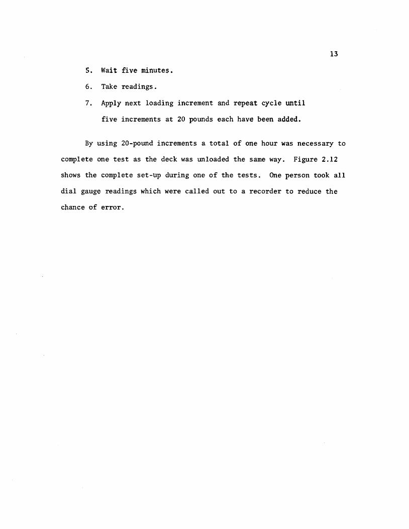
13
5 Wait five minutes
6 Take readings
7 Apply next loading increment and repeat cycle until
five increments at 20 pounds each have been added
By using 20-pound increments a total of one hour was necessary to
complete one test as the deck was unloaded the same way Figure 212
shows the complete set-up during one of the tests One person took all
dial gauge readings which were called out to a recorder to reduce the
chance of error
CHAPTER 3
FABRICATION
The orthotropic deck model was built of standard ll6-in and
lIB-in thick sheets of acrylic A laboratory check of these thickshy
nesses revealed that the 116-in sheets were 0061 in thick This
value was used in determining the section properties of the deck model
All connections were made by a gluing process thus simulating welds
in an actual steel deck Prior to fabrication of the model test beams
were built using proposed gluing techniques These beams were subjected
to heavy loadings which verified the adequacy of the welds Due to the
unavailability of desired lengths of material splices were required
Splices
The deck plate required a l2-ft x 6-ft sheet of liB-in acrylic
but the largest size available locally was 10 ft x 6 ft Therefore
a splice two feet from the end of the deck was considered Because the
10-ft x 6-ft sheet was 6 in oversized the splice actually occurred
lB in from the end midway between the last two floor beams This was
considered acceptable as the splice was 3 ft from the points being monishy
tored and in an area where the stresses were low
In order to provide continuous ribs a l2-ft length of 1l6-in
material was needed Again the maximum length that could be purchased
locally was 6 ft Under the circumstances it was determined that a
center splice in the ribs would be acceptable as the deck plate is
15
continuous over the rib splices The tie girder splices were made 18 in
from either end and staggered so that no two splices would coincide
All splices were made butt-joint style When a good fit was
obtained dichloromethane was used as a bonding agent where there were
inconsistencies in the fit PS-30 was used
Gluing Techniques
Dichloromethane a capillary action solvent that produces a medium
strength joint can be used only when parts are closely fitted with
no visible gaps The solvent is applied with a hypodermic needle along
the edge of the joint Capillary action draws the solvent between the
parts softening and swelling the plastic which then permits actual
cohesion of the parts After approximately five minutes the solvent
evaporates leaving a hard J clear joint It was found that a thickened
solvent could be produced by dissolving 3 percent clean plastic chips
in the dichloromethane This more viscous solvent had bonding charactershy
istics similar to the unthickened solvent but was more manageable when
applying
PS-30 a highly viscous polymerizable cement has little or no
solvent action and produces good joint strength after four hours
PS-30 comes in two components A and B Component A is a viscous solushy
tion consisting of a monomer and a polymer while component B is the
catalyst The shelf life of both components is six months the pot
life is only 25 minutes Before mixing the components should be
16
allowed to warm to room temperature for 12 to 24 hours Proportions
required to make PS 30 are
Component A 9S grams or 9S cc Component B S grams or S cc
After stirring for two minutes the mixture was applied to the joint
with a 13 gauge needle and 30 cc syringe
Although it is recommended that a V-type joint be used in conjuncshy
tion with PS-30 for maximum strength because of the small thickness of
the parts no V-grooved joints were used during fabrication PS30
was used only to overcome natural nonconformities in fit
Cutting
The plastic sheets were cut to size by a 10-in radial arm saw or
a l2-in table saw with a No 88 plywood blade To avoid handling the
deck plate it was trimmed to size in place using a 7-in Skillsaw with
a plywood blade
The l-12-in strips used for the rib bottoms were cut on the
radial arm saw (Fig 31) Out of 24 strips cut four were determined
to be unsuitable for use and had to be cut again due to a variance in
width For cutting the 3-in rib webs the blade was set at a 14 degree
angle providing the beveled edge needed for a proper fit to the rib
bottoms and the deck plate (Fig 22) Of the first six strips cut this
way three had to be discarded as they were as much as 14 in out of
alignment At this point it was decided to use the l2-in table saw
to ensure a better edge alignment
17
A total of 44 rib sides and 22 rib bottoms were cut To assure
that the ribs would be 12 ft in length when glued together two sides
and one bottom were bundled taped and then measured and trimmed off
in 6-ft lengths with the radial arm saw
Ribs
In order to hold the rib sides at a 14 degree angle while gluing
to the bottoms an eight-foot gluing jig was constructed to adequately
accommodate the 6-ft rib lengths (Fig 32) Foam rubber 12 in thick
by 1-12 in wide was laid on the bottom of the jig to provide a spring-
like effect so that the rib bottom plate would conform to the rib webs
during the gluing process The following step-by-step process was used
in the fabrication of trapezoidal ribs
1 Lay I-l2-in plastic strip on foam rubber pad
2 Place a I-in by l2-in wood strip on top of the plastic
strip
3 Compress foam pad and clamp in place using large C
clamps (Fig 32)
4 Place rib webs along the two edges of the wooden jig on
the rib bottom plate
5 Using small C clamps fasten rib sides to sides of gl~ing
form (Fig 32)
6 Release large C clamps allowing foam rubber pad to gently
push the rib bottom against the rib webs making a firm
contact
18
1 Apply dithloromethane to inside edge of rib using a hyposhy
dermic needle (Fig 33)
8 Wait 30 minutes then release small C c~amps and remove
finished rib from jig
9 Inspect rib for any opening along line and if necessary
reseal with PS-30
Floor Beams
Fabrication of the floor beams consisted of four steps
1 Cutting 8-in by 6-ft strips for web plates
2 Cutting openings in the web plates as shown in Fig 34
to accommodate the continuous ribs
3 Cutting five lIS-in x 2-l2-in by6-ft flange plates
4 Gluing flanges to the web
Some problems were encountered in making the web openings for the
floor beams The sides of the 3-in deep openings were cut with a radial
arm saw while the 1-12 in bottom was cut with a coping saw The same
technique as in gluing the ribs was used to glue the web to the flange
The flange was placed on a foam rubber pad and a series of clamps were
used to form a jig to keep the web upright (Fig 35) Small wedges were
then slipped under the foam pad where needed to provide the proper fit
Gluing was accomplished by applying dichloromethane to both sides of the
web No PS-30 was needed
Assembly of the Orthotropic Deck Model
After the fabrication of all the basic elements of the orthotropic
19
deck model was completed it was extremely important to follow a well shy
planned sequence of assembly steps The protective paper was first
removed from the deck plate and the ribs were placed on the deck in
their proper positions To provide a means of pushing the deck plate up
against the ribs a large foam rubber pad was placed under the deck (Fig
36) The ribs were positioned by using the notched floor beams as
spacers When all ribs were in their proper position weights were
applied at various locations to provide a tight fit Again wedges were
slipped under the pad to help make the deck conform to the ribs All
ribs were checked visually and with a thin feeler gauge for proper connecshy
tion to the deck The ribs were kept tight against the floor beam
notches by means of thin wooden wedges which were manipulated by a 7-ft
pole with a hook on the end
Pursuant a lengthy process of assuring that every piece was
properly positioned and fitted ribs were glued to the deck using
dichloromethane This assembly was left undisturbed for 24 hours after
gluing before removing weights and floor beams Checks were made for
places that were not welded properly and such points were reglued
using PS-30 After the rib plates were spliced at mid span the floor
beams were repositioned over the ribs More filing of floor beam webs
was needed in order to obtain a Eroper fit In the event of some gaps
(116plusmn in) which were too large to bond with PS-30 J small plastic
wedges were inserted prior to gluing In order to keep the highly
viscous PS-30 from pushing the wedges out during application dichloroshy
methane was used to spot-weld the wedges in place before applying PS-30
20
The floor beams were held in place during the welding process by
heavy steel bars lying over the tops of the ribs and clamped to supports
at each end (Fig 37) Weights were placed on top of the beam flange
to help hold it against the ribs The floor beam was then welded to the
ribs and deck plate After all floor beams were in place the deck was
turned over to check the reliability of the welding (Fig 38)
When it was determined that the welding of basic deck elements was
adequate the model was again turned over and the tie girders were added
The inside web of the tie girder was welded to the deck and floor beams
first The outside web was then installed followed by centering the
flange and welding with dichloromethane The total weight of the
finished assembly was approximately 125 pounds
Supports and Loading Beam
The model deck was simply supported on four corners by 2-in by
3-in steel plates (Fig 21) Two of these plates were placed on fixed
rollers (simulating a pinned joint) while the opposite pair was placed on
standard rollers
The loading beam consisted of a 10-ft aluminum H-shape supported
at loading point or points Two weight hangers were provided on each
end of the loading beam Each calibrated weight consisted of a fiveshy
pound chunk of caulking lead During testing a number of weights were
hung from the loading beam to obtain the desired load (Fig 39)
CHAPTER 4
TEST RESULTS
The Computer Model
A discrete element model capable of handing orthotropic plate
problems (18) was used for the analytical part of this investigation
The model (Fig 41) represents the stiffness geometry and support
conditions of an orthotropic plate continuous over flexible floor
beams The -principal features of this method include the representashy
tion of structural members by a physical model of bars an~ springs
which for analysis are grouped into two orthogonal systems of beams
and replacing the differential equations for orthotropic plates by
their finite-difference equivalent The problem then is reduced to
solving a large number of simultaneous equations rather than one complex
differential equation The computer program developed from the above
model permits the stiffness properties of the orthotropic deck and
floor beams to be included on an individual basis -thus resulting in
a more realistic representation of the bridge deck as an equivalent
orthotropic plate The bending stiffness of the plate in the x- and
y-directions and the Poissons ratio effects are represented by elastic
blocks at the nodal points (Fig 42) Support conditions are simushy
lated by elastic springs of appropriate stiffness at each joint while
twisting stiffness is modeled by torsion bars connected to the rigid
bars between elastic nodal blocks
22
Member stiffness and load values are entered in the ~omputer
program by first dividing the slab into increment widths of hand h x y
in the xmiddot and y-directions respectively Figure 43 shows the coordishy
nates of the deck model under investigation A joint is defined as
the intersection of the station lines in each x- and y-direction while
a mesh is understood to be the area surrounded by four jOints Or~hog-
onal flexural stiffnesses D and D are entered on a per unit width x Y
basis The torsional stiffness H is input on a unit width basis for
each mesh its value is determined with the aid of a separate computer
program following the method in reference (2) A listing of this proshy
gram is provided in Appendix ICa) Applied loads are assumed concenshy
trated at each joint therefore a distributed load must be proportioned
among the surrounding joints on a tributary area basis Unyielding
upports are simulated by introducing very stiff springs (500 kin)
at the joints on the support station line Discrete members such
as floor beams and girders can be entered on an individual basis by
giving their total stiffness values A typical computer output is
given in Appendix I(b)
Idealized Sections
The only function of the tie girders was to provide a flexible
support for the floor beams Therefore no attempt was made to properly
scale the tie girders~ as in an actual bridge their span lengths and
cross-sectional dimensions would be much greater ConsequentlYI
theoretical investigations by Chwalla (5) on determining th~ effective
23
width of the deck acting as the top flange of the tie girder could not
be used Instead this effective width was determined experimentally
by measuring girder deflections for several symmetrical loading condishy
tions and computing the required inertia needed to obtain this deflection
The tie girder inertia value was found to be 4434 in4 which corresshy
ponds to an effective deck width of 20 inches
The effective widths of the orthotropic deck plate acting with
a rib and floor beam were computed using the method outlined in the
AISC Design Manual (2) and others (23) It was determined that because
of its narrow width the tie girder would offer little or no rotational
restraint for the floor beams this justified using the full length of
the floor beam as its effective span when computing the effective
width All idealized sections along with corresponding inertia and
stiffness values are shown in Appendix II
Calculated vs Observed Deflections and Strains
(a) Deflections All deflections were corrected to account for
support movements during loading This was done by using a linear
interpolation of the settlements between supports Although a biaxial
stress field exists in the rib plates the use of uniaxial strain
gauges to determine strains at rib bottoms was justified through
experimental observations made by Erzurumlu and Toprac (9) Linearity
checks were made on deflections and strains for all loading conditions
prior to plotting any profiles
computed and measured center floor beam deflections are shown
in Figs 44 through 49 for all loading conditions At this juncture
24
it should be noted that the mathematical model does not account for
shear deformations The deflection due to s~ear was computed for a
lOO-lb load applied at the center of the floor beam and was found to
be 0023 inches If this correction is applied to the computed deflecshy
tions of Fig 44 the correlation between computed and measured
deflections would be very good with the difference reduced to less than
one percent Examination of floor beam deflection curves for other
loading conditions indicates that when the load is not directly over
the floor beam there is closer agreement between computed and measured
values This substantiates the need for a shear deflection correction
on floor bearns as less shear correction would be needed for smaller
floor beam loads It is interesting to note that good agreement exists
between computed and measured deflections at the tie girder as long as
the load is symmetrically located however as Figs 48 and 49 indishy
date a difference of approximately five percent exists when loads are
positioned in the driving lanes Thus the tie girder inertia value
and corresponding effective deck width are dependent among other things
upon the position of the load which is what Chwallas (5) theoretical
investigations indicated
Good agreement exists between experimental and computed deflecshy
tions of the ribs in Section 1-1 (see Fig 211) for the loading condishy
tions shown in Figs 410 through 417 Generally measured deflections
are slightly more than those computed with the difference seldom
exceeding five percent Again shear deflections may account for
25
some of this discrepancy as the difference is usually greater in the
center of the deck or directly under the loading pads Another possishy
ble cause of discrepancy is the localized distortion effect in a rib
produced by the moving together of the deck plate and the bottom rib
flange resultingmiddot in a lowered moment of inertia and section modulus
when a rib is under load In Fig 411 the computed deflection
directly under the load is greater than the measured deflection This
behavior is believed to be caused by the fact that the wheel load is
input as a point load due to the limitation of the mesh size Because
the 6-in long loading pad is centered over a node it cannot theoretishy
cally affect adjoining nodes In actual behavior however the load
is distributed to some extent to the adjoing nodes thus accounting
for the difference between measured and computed deflections on the
adjoining ribs An examination of Fig 417 reveals the same type of
loading condition resulting in the same relationship between computed
and measured deflections The extent of the discrepancy is not great
in this case as the load on each node is only one-half that of Fig
411 Generally when the load is over the floor beam the rib action
is fairly uniform (Figs 410 413 415 and 416) When the load
is in an adjoining panel centered between floor beams (Fig 412)
there is a slight rise in the center rib The decreased magnitude
of the computed deflection again is due to the load being input as a
point load A check of the strains at this point both theoretical
and measured reveals that the bottom fiber of the loaded rib is in
compression In contrast the adjoining rib bottoms are in tension
26
and thus verify the shape of the curve The deflections and strains
for computer coordinate (66) (floor beam bottom) are given in Table I~
Deflections again vary depending on the position of the load with the
greater percentage difference being when the load is near the floor
beam
(b) Strains Overall strains vary anywhere from 1 to 49 percent
with computed values generally higher than measured values The large
discrepancy between computed and measured strains is probably due to
the following causes
1 Instrumentation error
2 Warping of the deck due to uneven support settlements
3 Idealization of the structure as a discrete element
model
4 In the case of ribs the assumption of a uniaxial
stress field in the rib bottoms
The instrumentation error could be as high as ~20 ~inin
and would account for a larger percent difference between computed and
measured values in low ranges Therefore readings less than lOO~inin
would be too small to verify the adequacy of the discrete element comshy
puter pr~gram
The warping effect could also cause plus or minus strain errors
depending o~ the magnitude andlocation of the sUPPQrt s~ttleIlJ~nt$
27
A safe assumption is that the more warping the greater discrepancy
between computed and measured strains As an illustration referring
to Table I the 30 percent difference in loading condition F could
be due to warping because of the unsymmetrical loading in that case
An examination of the support deflections reveals that Gauge No 7
drops 0049 in while the diagonal corner Gauge No 9 drops only 0011
inches This indicates a warping effect and a possible explanation of
the 30 percent discrepancy
While the accuracy of the discrete element model could be
improved by using a finer grid the mesh size chosen was considered
adequate for the purpose of this investigation and prevented excessive
use of computer time Because the theoretical data generated for
deflections and bending moments are average values there will likely
be some differences between experimental and computed values The
errors introduced by assuming a uniaxial stress field in the rib
bottoms would have some influence on the computed versus measured
relationship which would be more apparent when the ribs are heavily
loaded
Computed and measured strains for most loading conditions are
given in Tables II through IX Keeping in mind the previously
mentioned possile sources of error there is generally a good agreeshy
ment bet~een theory and test results It is interesting to note that
when a load is directly over a rib (Tables III and VIII) the computed
strain is considerably greater than measured strain--38 to 49 percent bull ~ ~
28
This can be partly attributed to the load being input as a concentrated
load and partly to the excessive distortions of the rib plate directly
under the load This localized distortion effect was also noted in the
investigation reported in Reference (9) A check of the floor beam
strains near the girder (Table II) Gauge 1-7 indicates there is tension
present at that location Although the strains are too small to be conshy
clusive it indicates the assumption made earlier which stated that
the tie girder offered little or no rotation restraint for the floor
beam was reasonable
It could be concluded that within the limits of the experishy
mental program the orthotropic deck responds as predicted by a discrete
element computer program in the elastic range
1
CHAPTER 5
CONCLUSIONS AND RECOMMENDATIONS
Conclusions
In view of the findings documented in Chapter 4 it may be conclushy
ded that
1 Plastic sheets of acrylic can be used as a modeling material
for the fabrication of orthotropic deck models Ordinary
woodworking tools are effectively used in the deck construcshy
tion thus keeping costs to a minimum
2 Dichloromethane and PS-30 are compatible an~ effectively
simulate welds in steel orthotropic decks when tests are
conducted within the loading range of this investigation
3 Creep effects of plastic do not adversely influence test
results when proper testing procedures are used
4 Indirect models can be constructed from plastic acrylic
material to test structures as complex as orthotropic decks
5 The discrete~element model proposed by Matlock and Panak (18)
is effective in predicting the moments and deflections
along grid lines of multiple panels of orthotropic decks on
flexible supports
30
Recommendations
Future investigations involving orthotropie bridge decks should l
based on this study be concerned with the following
1 A computer program using a finer mesh size should be run
on this model to see if the results would change signifi shy
cantly
2 The deck should be supported on concrete blocks so that
warping would not be a factor in recorded deflections and
strains
3 The box girders should be properly scaled so that a check
on its torsion restraint could be made
4 The model should be extended to a length such that a full
AASHO Highway vehicle could be simulated as a live load
5 Investigations should be conducted on the interaction of
the rib and floor beam by extensively gauging the areas of
intersection
6 Decks using different types of ribs (open biserrated etc)
should be modeled and their response compared with those
obtained from closed rib models
7 Orthotropic decks on flexible supports should be modeled
with steel as a means of checking the ultimate strength of
the system
REFERENCES
1 American Association of State Highway Officials Standard Specifications for Highway Bridges 1965 Washington DC
2 American Insitute of Steel Construction Design Manual for Orthotropic Steel Deck Bridges New York 1963
3 Boussinesq J V Complements ~ une Etude sur la Th~orie de lEquilibre et du Mouvement des Solides Elastique dont Certaines Dimensions Sont Tres Petites par rapporta LAutre Journal de Mathematique Paris 1879
4 Cauchy A L De la Pression dans un System de Points Materiels Exercices de Mathematique Paris 1928
5 Chwalla E Die Formeln zur Berechnung der vollmittragenden Breitediinner Gurt und Rippenplatten Der Stahlbau No 10
1936
6 Cornelius W Die Berechnung der ebener Flachentrag-Werke mit Hilfe der Theorie der orthogonal-anisotropen Platten Der Stahlbau Vol 21 1952
7 Engineering News-Record Californias Orthotropic Bridge Set to Go October 29 1964
8 Engineering News-Record The San Mateo-Hayward Bridge A Fabrishycation Dream June 23 1966
9 Erzurumlu H and 1oprac A A Research on the Deck Elements of the Ammi System Structures Fatigue Research Laboratory Report No P550-12 The University of Texas Austin March 1970
10 Geckeler J W Elastizitatstheorie anisotroper Korper Handbuck der Physik Band VI Berlin 1928
11 Gehring R De Aequationibus Differentialibus Quihus Aequilihrium et Motus Laminae Crystallinae Definitur Berlin 1860
12 Guyon Y Calcul des Ponts Larges ~ Poutres Multiples Solidaris~es par des Entretoises Annales des Ponts et Chaussees No V Septembre-October 1946
13 Hardenherg G J Design of the Superstructure of the Port Mann Bridge1f The Engineering Journal July 1961
14 Hedefine A and Silano L GI Design of the Fremont Bridge ASCE National Structural Engineering Meeting Portland
32
15 Heins C P and Hails R L Behavior of Stiffened Curved Plate Model Journal of the Structural Division Proceedings of the American Society of Civil Engineers Vol 95 No ST-l1 November 1969
16 Huber M T HDie Grundlagen einer rationellen Berechnung der kreuzweise bewehrten Eisenbetonplatten Zeitschrift des Osterreichischen Ingenieur - und Architekten-Vereines Vol 66 No 30 1914
17 Massonnet Ch Methode de Cal cuI des Ponts a Poutres Multiples Tenant Compte de leur Resistance ~ la Torsion Publicashytions International Association for Bridge and Structural Engineering Vol 10 1950
18 Matlock H and Panak J J A Discrete Element Method of Analysis for Orthogonal Slab and Grid Bridge Floor Systems Center for Highway Research Report No 56-25 The University of Texas Austin May 1972
19 Mayer R Die Kurpfalzbrucke uber den Neckar in Mannheimtt Der Stahlbau Nos 6 7 8 1952
20 Naruoka M Okabe T and Hori K An Experimental Study on Model Continuous Beam Bridge with Steel Deck Publications of International Association for Bridge and Structural Engineering Vol 18 1958
21 Pelikan W and Esslinger M Die Stahlfahrbahn-Berechnung and Konstruktion MAN Forschungsheft No7 1957
22 Shields E J Poplar Street Bridge Design and Fabrication Civil Engineering February 1966
23 Troitsky HS Orthotropic Bridges Theory and Design The James F Lincoln Arc Welding Foundation August 1967
24 Troitsky M S and Azad AK Bending and Torsion in Orthoshytropic Deck Box Girder Journal of the Structural Division Proceedings of the American Society of Civil Engineers Vol 98 No ST-9 September 1972
25 Voigt W Lehrbuch der Kristallphysik Leipzig 1910
26 White Richard N Similitude Requirements for Structural Models Conference Preprint No 469 ASCE National Meeting on Structural Engineering Seattle Washington May 1967
-
P
- () ~ -4 X ) -- tQ - 0 -I ftl
rshy ~ r 1gt
-1
C It (
~
~
shyo
Z g
- c o-Z
Ie
CP C
---
-
-n-G ~
0 1tI lt
0
t IfI Z J ()
Z P
I I
I I
I
I I
I i
I
-tshy I I t I ~
I I I I I
~
t ~
I r-shy
1-shy I I I I I I I I I I
I I I I
I I I
-
I
I I I
I I I
I I
Imiddot
-
bull shy0
--tshyI
I po U
Q r---shy 0
I i
~ 0
I
)0
~ omiddot-0 ~ T bull l
l
~LO II
OOlte
middotOOmiddot~middotmiddot---I
GLQ ~olt -rL1
OO~ 00laquo
gt o obull
tf
CNOIN~HIO
0 ~~HM 9middot21middotCJ1~ bullPti Z
JJd 1fO 1nJS 4MJ ~Q dOl H1 14
1 QJO01 d11t19ff
bullIampZ Ie I~ J~fianlt ~11aM flU iD dol 4tU J ~41~ JatlN~
(l~t1n4Ci( -amiddotl1f14 oN1
01 l7Z til
OJ oz z
01 Oll 9
CHWI
L$ C~HN
~ tdl Nt
dVO ~aHM
1g=3HM NaJ t11 -10 4-a~ l 11NO lt middot21middot)~ I
~JJM irtJ ~del erialJ 4211 J ~oJo ~1J
lfLNO ~1(11l1
~=3a1 IN=lfn~J ClJ10 llJltCnlt i3U (1110C odo 11 11lo~
OZltH --ao~ ~~IC d ~NIO~O 1z middot~Id
fa tt a oe 01 ---~l
Z~
01
~Yiq~~ ~a~rAJJlta
~ta ~o J~ ~fd ~
1 ~shy ()
~ 0 Id
lj~t43001~ N~~Ml~Q t+1r+1ML=aca ltofd d
CI 0
H1aq ~OG1-l -10 ~ clta Ia If CO vd ~
1 0
------
N k I
C () n -till J
~-9ca (1001 d) lY bull ltltlIa N~~Mll ltQ~d -
I~ raquo ~
1 ---1-- 0 f 111
)~
c ~aq 2I001-i N~~Ml Haca 7J001d -~Cd ~ C317J 11 ta~d -(f) -io bull ~I2J LV 011d bull
I 1)1 ---shy-PJ----4---+ 0
Q 9
AI
~-lf11 l J
--shy-~---t----- -
j~
0- lIf
--
-~ o
I Imiddot I I I I
I
I I sa I
bull- bull
tEl - - l=~ Abull -C)
bull ~
I II
I I I
I ta I ~ ~~ lar I j Il~ CP e 0
tIbull
~bull ~ -shy
[l ~ 1-1 -T
bull --1 bull bull bull -~ Jl 1 bull -abull ~ I I I I
~I I JQ
Ql I I I I ~ tf of(
Jl ~
tclXll~~4 1IDD~ _ I - r-
if bull(Jill i I
I
I I
I I
II
I
ot
---
-
II
G ~
-
r 0 ~ tgt
0 ~
Z
~
0 tgt r
G 1gt C lti
I I I I
I I
I I I I
I I I
I 1
-- _shy - - I
I I t
t I
I I I
I I I
1 I
o~ P~ t (~ lt1gt1= c~ bull bull Q )l ~ ~ -
i I
I shy
I I I I I
bull bull oa I
~
1Q I I I i 0 I I I I I - I-4
~
I
~amp~faq 2Joo -I -shy -I r J --1-shy I I I
I I I II
I
_L
ED CD agt
)02z[
lQ ()-C0 ~UQ
)
0 ~ It )10 U
-1-
U t J
t -0 0
42
Fig 212 Test Set-Up During Testing
Fig 213 Bridge Used in Deflection Measurements
43
Fig 3 1 Radial Arm Saw Used fo r Cutting Plastic Sheets
Fig 3 2 Gluing Jig and Clamps
44
I
Fig 33 Application of Dichloromethane to Rib Seams
Fig 34 Cutting Openings in Web Plates
45
Fig 35 Jig Used in Gluing Floor Beam Web to Flange
bull Fig 36 Deck Assembly Prior to Gluing
46
Fig 37 Ass emb ly Us ed to Hol d Floor Beam In Place Prior to Gl uing
Fig 38 Turning the Deck Over
( gJ ) 1=3COH JN~r~1-=3 1~-iZJca HOCl-i LNIOr 11dkl z-v middot91j
( qy) ~L~1d I d0211oHJ2IO -10 1aOH LN3H31~ JJ~ZJC(j -tJl-i
x~~~____________~
2
-r
middotat
x 2~ 1 01 ( ~a ~ C lt~ ~I 0 --u
-~ ~
~~ ~ f) middot)(4
D b-
~o
~4 t IU
1)1 G
J
-n I~flt)(~L1J) middotPN ~9H-(i ~
~ I -1 rT nn rrrr1 TTlVf- d)
bull ~ d~Or lID IIU IIJJ LUJ
)Y 0 (01 q ~V C1JC101
0
() shya r --hTIm I 1111 I~
l~ ~ I1II
D -0 -aN 00~O1 ~ tJ4 o~a ~o - c - -I P
ct 10 -~ lti -shy IQ
1
-) ----- _bull -tt -shy-t
-(p
0
~ 0
I)
-~ ~
~ P
~ ~ 61
0
~
~ ampgt p ~ tt Z 4 m ft
r () 0 F
0 ~ 1gt - ~
w r n ( -4-~ 7shy
r 0 Cgt 0bull ~ ()
7 C 0
bull () G to a
C -I Il 0
0
0 tI
r
0-
0 0-
- Q 0 I
0 I ~
0 0 00
I Z z ( r tT ~ lti
~ ~
- 0
( -l -I t -a 7 ( -4
11 r l1
r ()
~C ~---- ~ ~ shy ~ - 0 8~ ~ tIshy -
bullbull 0 1 0 0 lt) 0 r 1t ~ r (
t - -()
L
) P P ~ C)
Z P Jgto
0
p
~ 1 Qshy
~ s
l Z -4 n f)
r l 0 1
G ro P 1_ Q t( l r ttl ( -- ) Z
r (l 1gt
~ ( () Z 0 Q
() 0 0
()
i I
-
~~ -1)
-~
-~
~~ -
-~ ~
-a
-() II
()
U ~
-~ f(0 1gtshyt(J ~~ e w ~o 0
() C)
~ () -()
i I
9 ~
~
~ t1 L --I rt ll
r -
C) 0 1
~ w I_ 0 t
r w (
-- - -Q
Z
r ~ 1gt Q ~ 7 ~
~
1 r IT (
--
o~ I -z ( I It
~
~
~
~ -~
() shy
~ N l 0 () ~ U
LS
G - ~ 1
rshy)
~
$ 1gt
r shyo l -r r f(1
--l )
7
-
0 It 1 r It t - 0 ~ ~
-Z 0
~ I 0 O~ z I (
~ -~ ---] m ~
N ~
ii ~ 0 -ltP shy ()
IT 1 ~
t
)
~
~ -~
lt)
I
shy Gmiddot ~
-
r (J
It
Qrshy-~ t) l ~ ll () () 1
W bulli
rQ
1gtshyi
w~ r ft ( -t - 0 7shy
r ) 1gt ~ middot ) ~ Z
middot ~
n
- 9
-~ -J IT ~ --shy0 Z II-shy
~ n r
-4 )
z N Ol - fl 0
rshy r ~ Igt 0 ~ Z ~ l
~ Sl-() 0
~~ Ot i i
I shy~ a (l
~ 1)( c~ ((
wo u
0 fT shy
t) t) IT 0
~ 8~ 0 -l
(5 I ----I I Z C Z ( I (T
~ ~ ~ 0 ~
I J~ t1 (( --lshyshy( () 1gtshyZ ~ bull
U It
rshy bulltI shy-II =Jesshy ( --
l -I 0 z 8shy 0shy
fl ~
l (
0
rshy(l
r t) 1gt ~ bull ~
z ~
~ Jgtoo
~
~ o I
~ ~
-)l J
~ ~ 0 z
-I
0 tr -p r 11
n Q Z ~shy P ~ ta 0 1- r - r ~ 1gt ~ ( Q1 ~
(~ 0
t -0 C 0
0 fJ
rshy rn (
-~ ~ ~ -I 0 o 0 0 o bull ~ 8~ I I bull i I Z
--
1--shyZ ( I
-~ en ~ ~ ~
1 ~ -J ( -
0 z --
~C-~~O - f1I -~TI ~r
0II (
--- 0 ~ 0 ~l~ Z 0 1
1Q
Ibull
-~~~ I -~~ _1G -() 0
~o S
rshy f1
r C) 1gt 0 ( 0 Z -0
0
--s U C ~ 11 0
9
-l ( ~
-4shyt) z bull
- 0 n
rshy (t1
--l t) Z lQ
-0 -a fQ () r
r 0 ~
~ ( () Z ~
sgt
0 IT -n r IT ( -l
0 Z Z ( -t ff J
6 -I bull ~ S
N
0 0 ii ~
S) p ~ ~ ~ -0 0 6
8 o ~ 0 i I i I
~ ~ -~ U ft C
shy0 z -- - - Cl1
- r~ - lr-
-~ ( 11 0 1gt
to ) -0 C C f3 -t t Cl1 ~ 0
t~ shy 0 ()0 z
r
r ) 1gt ~ f ~ 7shy9 0
~ -J
t
(p ~
0
C
() 0 ~ 08~ o~
i
~ ~ -J shyl 11 ( -t 0 Z bull-~ rshy Il t ~ --- --I-~
() 7shy
N tl 0 P
Q lQ ~ ~ lt)
r ~
r Il (1 WI
r r 0 0 1gt tgt 0 ~ ( ( tgt a Z z 0 0
t ttl
I ~
1 (
o I
~ c ~ 1Q
ltV 0 Q
- ltY-o o 0 I
C
TABL
E I
FLOO
R BE
AM D
EFLE
CTIO
NS
FOR
GAUG
E LO
CATI
ON
1-5
FL
OOR
BEAM
STR
AIN
RE
ADIN
GS
FOR
GAUG
E LO
CATI
ON
1-9
LOAD
iNG
CON
DIT
ION
r
A
B
C
D
E
F
-
Com
po
Mea
s
Com
po
Mea
s
Com
po
Mea
s
Com
po
Mea
s
Com
po
Mea
s
Com
po
Mea
s
Def
lect
ion
(1
-5)
Inch
es
011
4 0
124
013
5 0
151
011
3 0
124
013
2 0
145
011
0 0
116
013
0 o
~42
Com
pute
d M
easu
red
091
0
89
0
91
091
0
95
09
2
iStr
ain
(I
-9)
Mic
roin
ches
17
5 20
6 61
8 53
1 15
7 17
3 44
6 38
0 12
2 13
7 33
8 26
0
Com
pute
d M
easu
red
-shy~-
085
1
16
----_
__
_
__
shy_
_shy
087
1
17
-_
shy
089
ff
13
0
P =
100
LBS
til
--
J
58
TABLE II
STRAIN READINGS FOR LOADING CONDITION A (1
I
~ (1)
cQ
~ 0 0
~
~ (1) +-gts (1) u
GAUGE NUMBER Computed u in in
Measured AI in in
ComEuted Measured
I-I 873 789 111
1-2 679 660 103
1-3 510 495 103
1-4 361 329 110
1-5 229 202 1 13
1-6 - 1-7 -
-- en
Jl 0 - bull
s 0 +-gt u (1)
til
11 3 205 208 099
11-6 202 229 088
11-8 194 199 097
11-9 183 173
-106
11-10 170 147 116
- -g g instruments
P 100 LBS
ji
I
59
TABLE III
STRAIN READINGS LOADING CONDITION B lt
~ (J)
Ql
~ 0 0 ~
~ (J) ~
53 u
Computed Measured Computed GAUGE NUMBER u inin JIJ inin Measured
I-I 599 599 107
~
1-2 486 495 098
shy
1-3 375 379 099
1-4 272 251 108
1-5 176 156 113
1-6 -
1-7 -
r- en
0
r-I ~ -
I
sect r-I ~ U (J)
U)
-11-3 2429 1635 148
11-6 453 593 076
11-8 238 242 098
11-9 202 174 116
11-10 -
Too small and within the range of tolerance of record1ng instruments
Wheel directly over rib P = 100 LBS
60
TABLE IV
STRAIN READINGS FOR LOADING CONDITION C 11
Computed Measured ComEuted GAUGE NUMBER ~ in in AJ inin Measured
I-I 587 500 117
1-2 601 559 108 I
i
I
~ 4)
CQ
ft 0 0 -c u ft G) +J
5 u I
I I
1-3 531 507 105
1-4 377 326 116
1-5 241 190 127
1-6 -
1-7 -
tI)
c c oi
-c
-c
s 0 +J 0 G)
U)
11-3 198 160 122
11-6 196 184 107
11-8 190 154 123
middot11-9 180 133 135
11-10 -------- shy -
Too small and- within the range of tolerance of record~ng instruments
P = 100 LBS
jl
~11~~---~middot
61
TABLE V
STRAIN READINGS LOADING CONDITION D 11
Computed Measured Computed GAUGE NUMBER u inin M inin Measured
I-I 424 397 107
1-2 427 439 097
a (J)
i
~ 1-3 378 389 097 ft 0 0
u 1-4 275 271 101 ft Q) +oJ s (J) 1-5 178 160 111u
1-6 shy
1-7 shy
11-3 341 293 116
~ 11-6 844 760 111 en c -t et J
II~8 832 731 114 t
s 0 11-9 260 220 118
-If +oJ
-0 Q)
CI)
11-10 192 159 121
Too small and within the range of tolerance of record1ng instruments
P = 100 LBS
c
62 ~ bullbullbull ~ - ~~ ~ ~ W bull
TABLE VI
STRAIN READINGS LOADING CONDITION E
Q)
eQ
Jot 0 0 u Jot Q) +Js Q) u
Computed Measured Co~uted GAUGE NUMBER ~ in lin AJ in lin Measured
I-I 435 395 110
1-2 558 514 109
1-3 495 478 104
1middot4 451 431 105
4241-5 380 112
1-6 206 165 125
1-7 -
(I)
c~ cx gti
I
6 ~
+J (J Q)
Cf)
11-3 185 152 122
11 6 196 181 108 bull
11-8 205 175 117
11-9 209 158 132
11 10 - Too small and wi thin the range or to1erance-of recorc1Jng
instruments P = 100 LBS bull
bull
63
TABLE VII
STRAIN READINGS LOADING CONDITION E1 2
Computed Measured C0RPuted GAUGE NUMBER u in I in M inin Measured
I-I 435 380 114
1 2 331 294 113
1-3 243 195 125
~ 1 4 169 138 122ltD co $-I 0 0 1-5 shy u $-I ltD +l 1-6 shy= ltD
u
1-7 shy
11-3 1
185 137 135
11-6 170 152 112 en
0 5 11-8 153 135 113 bull r 11-9 135 112 1200
- +l -0 ltD
Cf) 11-10 shy Too small and within the range of~ tolerance ofrecording
instruments P = 100 LBS
I
64 ooo _~~ _ bull
TABLE VIII
STRAIN READINGS LOADING CONDITION F
Computed Measured COIDEuted GAUGE NUMBER ~ inin~ ILl in lin Measured
I-I 317 265 120
1-2 388 346 112
1-3 349 331 105~ CD
bull cl
~ 0 0 1-4 313 292 107
14 ~
~ CD 1-5 282 243 116sCD u
1-6 shy
1-7 shy
11-3 309 357 087
~ 11-6 1343 975 138en I 0
c J
14 11-8 337 412 082 I
14
r 0 11-9 339 382 089 0 CD
CI)
11-10 1349 907 149
Too small and within the range of to1erance-or-recora1ng instruments
Load directly over rib P = 100 LBS
65
TABLE IX
STRAIN READINGS LOADING CONDITION F1
-Computed Measured Co~uted
GAUGE NUMBER ~ in lin AI in lin Measured
I-I 317 253 125
1-2 250 206 middot121
~ 1-3 191 146 131 (I)
al
ft 0 0 1-4 shy 11
tI
ft (I) 1-5 shys (I)
u
1-6 shy1-7 shy
11-3 309 331 093
U)
c II-6 197 180 109OM rt - 11
t 11-8 169 140 12111
s 0
OM 11-9 147 112 131CJ (I)
tI)
11-10 shy Too small and within the range of tolerance- of recordLng
instruments P = 100 LBS
- ~~ - - -~~ bullbull gt~~bullbull - ~
SDNI1SI1 ~DO~d ~31ndWOJ
I XION3ddV
67 ~ ~ ~ bull ~ ~ _~ a bull- ~
I(a) PROGRAM USED TO DETERMINE THE TORSIONAL RIGIDITY
JIDI 8-DIP11I O A IlIBCDO 1101
I I RIM THIS PROGRAII FIOS THE TOaSIGIIAL RlalDITY POil ORTlIOllIOmiddot I 11M PIC DICKS WITH fRAPIZOIDIL RSBS 3 RD II-THleDUS 0 tHE DICJCPLAtS I 6
IUQIJ TbullbullTHJCKIIUS O~ THB alB PLATa RDI A-WIDTH 0 TId IlIB ca) Rill la-SPACIIII or TRS RIBS (I
1aUDa DECK bull aIR H8-LH or 0N8 SIDI OF A RIB e-WIItTII 0 tal BASS or tHamp 81B 10 8M s-NODULUS 0 ILAITICITY I O-GDULUS O RIGIDifY S-ACTUAL SPACteO FLOOR 8EAMS 15 READ tlT8AIalWI_bullbull8aGS 80 u-eeHe+ 30 AlaquoAl8~H 0 K-CbullbullA-CtU(AItlbullbull pbullbull- 44 PRIWT -tHE tORSIONAL STII II CK-I--IP so 1CTImiddot3186e 1(Te~fl)middot3YO 10 LI(middotAI+8-CA1bullbulliB~I-CRImiddotAI~3CSImiddot8))OLI--H-CA-+AI--bullbull-aRI-AI-3 100 LLI~~CAI8Le)
10110 c(~a(AI) ce(~e(AJ-~AI)middotlaquo bullbullbullBI)CAIbullbullraquo)C8lC8A)
130 V-middotJtZImiddotfAI-C CAI+CI -(1~16I1-8 Vbullbull(ampI~A)middot3C(EImiddot(AIBLmiddot1150 V3eCLmiddotftlCAI)middota(IRI(H~A-CCI-bullbullCICbullbullCmiddotala160 v-vcveV3) 171 V-V I PRIIIT -Ha TORSI8IIAL RIIUCfIOactoR ISmiddotJV 110 HbullbullbullSC(Vbullbullbullbull)CA+Bl)) S PRIMT-IKE fOBSIOaAL RIGIDITY IS ca-I-I-bullbull 300 DAtA 115bullbull0e3bullbull 3bullbull 3bullbull 30311~19336bull bullbull9 DID
READY ItUN
AX SOPDI 33 fHa TORSIOIIAL ItJr-as II (Kmiddot middot) 19711 THZ TORSIONAL RIDUctlOM ActOR IS O1681~2 THE TORSIaAL RIGIDITY IS (XmiddotI-8IN 151906
il
68
I
Ieb) PROGRAM USED TO COMPUTE DEFLECTIONS AND MOMENTS
~R08 I LOAI) cobullbulllfttr- middot-middotnNE jHit(-lilrTifCNTEIt 0 OIctC Loio- bullbullbull lei
rAil I COttTrtOL DATA- - ---------------
__--y flkl NBIIt-_ -__ bull 3 I-
HOLO RO IRCpoundDtfC PR08 CI-HLt -0 bull - i ~I - HUtt CIRDS-UIJUT TftllltOI[[- I J ~ 4 __t bull
- rI8[ 2~ CGHSTDTrshy
NUM8pound1t 0 tNtItpoundENfS tN x middotDtrtpoundCTlormiddot middotxmiddotmiddotmiddotmiddot middotmiddotmiddotmiddotmiddotmiddot middotmiddotmiddot_middotmiddot middotmiddot-middot middotmiddotmiddot_middot-- middotmiddot -middot-middot--middotmiddotmiddot-----2 ----- middotmiddot-NUits-or-YNcRfMENfs IN dIRECTION My z
INCREMpoundNTLNGTH INX OmiddotIItfImiddot ttx - -- -- -middot-- -i-~middotjmiddotiabullbullbull shyINCItpoundIitNT LENGtH IN ot_poundCTtONmiddotH middotmiddotmiddot middotmiddotmiddot-middot middotmiddot-middotmiddot-middot- -middotmiddotmiddot-~ middotbullbullImiddot+middot
- ---- pbISS-ONS___lTro--- - I SLI8 TICtCNESS cfmiddotaimiddotmiddotmiddotmiddotiiilwmiddotptCljA[-M(hpoundN-fmiddottSmiddotCofllPUfeifmiddot----middot---------
--I spte lIEfJ ti_ tmiddot ncrIL STHSS _ -_-- __ _-_shy
rilL J JOINTmiddotSTIFFNESSINOlOIOmiddotDIT shy
- - - - ---_ JlY -middot middotmiddotmiddot-u_middot -_middot -- ----T----shytn OXmiddot TltU JOINT JOTNT
emiddotmiddotmiddot bull 1 2 middotmiddotmiddotT~-middotmiddot-rlr-Df-- ffJS-C 0middotmiddot-middot-middotmiddot---middot- --middot1---------middot --1middot------ -- -1 o 0bull middotmiddotImiddotmiddotIIJlr-IC-4poundr -1-~ --- ---- -0)---- - -- -- -_---- -----shy
D 24 II 24 -11ltl2 -496tGI -I -0 -I -Ibull __d -6-11middot-- 1 ----------- -----middotmiddotmiddotbullbullZ1--D----- -I ---------- shyJ -12-1 -middot-12-middotD~-middot----middotmiddotr----middot-middotmiddotmiddot---middotr-G7middotI-middot-I _ ---___-_ D II 12 II -1 -a 12fpound+G -0 -0 -0 111 r ---- bull-- --middotmiddot-middot-middot--middot-----lI7R middotT-middot--middotmiddot ----------bull(-- shy1 2~ rr-middot2~ middot-0-----middot--------middot--middot --middotmiddotmiddot-middot middot171poundbullbull[1middot-middotmiddot __middotmiddotmiddotmiddotmiddotmiddot -----bullbull------ --------shybull D I 2 -0 -D -a lffEf -I -I
-TI--TmiddotII-y-l~-middot----T-middot--middot --------------r7~bull - ---- ------ shy_ -- --- ---1 -I ------- --- - ---------T-n-shy
12 bull 12 1 -I -D -I -I -0 bullbull11112middot-ii-middot-z -0 _o-r bullbullbull bull~- ~ jbullbull bullbullbull
middotmiddot-ftmiddot middotmiddottt11 2O~ middot-a 0 ~ 0 -0--- - - - 112 _ - ----_ -__ - ----- --~- -- - -- _---- --~ -shy
fllEmiddot ~ middot JOIN SfI rsSAND LO AO 0 If- CONTlfmiddot-middot-middot-middot-----middot- middot ------------_____
--Iof middot_ltu middot Itbull it ~=~~t~~= ~~ ~ --J(-JOINT JOfNf
0 pound
-rAIL-middot----S1fSrl1NISStJIfImiddot--middot
middotmiddotlto -- TRU MESH -~poundSf
___J___ JI~_~]~ 2~_~ 19pound+IIJ
- raIL middot6~-middotlfjitmiddotmiddotSTlNpoundSS J ATA --~- - -- ---~ -- - ----shy
FROM fARO ---IAft BAitmiddot
n
---__----shy fI1 JSIY
--
__ __
69 l(b) PROGRAM USED TO COMPUTE DEFLECTIONS AND MOMENTS (Cont)
NONE
---------------------------------- shyraBLE 7 MULTIPLE LoaD OaTamp
FRO- lTIfRO--------- ---- ---- ----------- ----- shy Gil ~
JOt T JOINT
--- r-middotmiddot-f--------- -Iooa-II
_ --_ -- ----------~-----
---- ------------- --_------ _ _ ------------~----- ------_----shy
---1
ItOltaM SLag middotOpoundLDCI( -- -[NaUS - middot-middot--------middotmiddot-ltrfSlOijmiddotflffmiddot-O~middot-(jmiddot-69----IfaXIN~- -PTAOTlopIC OECI( iiiI 1973
LiSTie ORTHOTROPIC OEC( --------- -- -------- ~ -
I ------ ~- ----------shy
IItOB (COT ---j--- 0-=-IO=--C-ON=D=I=T=~~middotN---a=-_-9Neuro=_==HEJ _~o~D J_~_Jl~rIt~_F_)~c~ _l_~~()_u_J_M_ ___________
-------- --- _-__------------------------------__--_-------------shy-rAlIlE a USOCl
Staa MOMENTS aRE PElt UNtTMIlTH--middot------------------------------- shymiddot--~ara opoundNfS-i-RE TOTAL P~~ REa
X TWISTING MOMENT bull - TWISTING M(tEltT--middotmiddot----------middot---------------middot----- shy~- 8a aNGLES aRE COCICWYSEmiddotmiddot -~-
SLa x SLas - - --~-~- S( A-B ---(I~GESf- -- 9pound--- ~----------MOM- 0--middotmiddot- x ------ftttINctal xTO--shy8EA x 8poundIM Y TWISTING ~lA8 lARGEST s~
DrIP -- -OMENT-- MOpound --OMtff -OpoundT- - - OENT RpoundampCftON--------shy--~ - -~ ----- ------ - -- ------ shy-~--yen------~ -~-
bull -DIOE-I -211amppound-20 1Damppound-16 1214pound-0 124-O -40 ZSadE-aZ --- _ -6215E-15 3232pound-13 -- ----~ ---------- -------- shyr r~---2S65E-O middot 229I1E-0amp I ampE-13- _middot pound-06- - 9--middot------ shy
1~6~ D I - 2- -~ a06E- 358E-O GE-16 ~r9IE-6-2~209~6 - ~
- - - 10 UE-G 2 j middot3pound-1 1466E-OII 13SE-02 ft- middotr~--6 Z26E-0 3gE-O amp
1133E-2 -- I --Z-6-67E- -695E08
- -- fO SSpoundmiddot2 z4 -59~- 36 bullbullE-08--- - --- --- - - ---1061 pound-a 2
-------- -6167pound-1---1695pound-08 1085E-D2
- 2tt -6Z26pound-I - 3 ca-olt ~~ ------ ~ --1I31E-02 -516pound-1 ~5amp~~-UI - - -- -- 11 3fE -02
11- z~middot- D6E-t_-- 3S8E-D
a - - - 14IE-6 IS2E-d 937t~-07 -ijij O O~ - ~--- --- -- -- - ------ ---------- shyI E-16-2~ 6a9E-D7-2IIr~pound-7-2 9- I o Zbullbull35pound-16-71S1E-01 7 -01 -3-- crshyD----middot----------- shy2835E-16 3334E-14 361-18 -G ma ----- -- -shyO - 72~-a7( pound-07 --~ 3---0------- shy
_d bull 118-16 6041-07 2104E-a--29-~----o - - -~--------------
2815pound-1 -9112~-Ol 9JfIE-01 i44 d bull O ---------- ----------------- shy~ __bullbull-Cbullbull ~-ua ccipound-6 ~ I
IDI6E-D2 a n ---Z-216Jpound--4- 229iiE-~a I f~-16-3133Ea6 --- pound---- --r-bullbull
-----~------ ----726pound-03 - It ----- --- --------------------- ------ ---------- shy
ii
1300N dO S3Il~3dO~d SS3NddI1S
II XION3ddV
71
lt
12000 --middot--middot-- l~ fb ~PAcJ6 (j ~00 lb 00_
~~
~ FhshyN 1-- II II
~()
0 lIZ 12amp di
1fJ J 2 1r
IDfAlleO 5fCTON
L_~middot_90J ~
Aeamp ALItI) DI5TANGfXIV) A)((t) A)(f(n4) ( InA) 1A~L (In)
DE-C~ PLA1Eshy 2500 Oo~Z5 0 I~ OrxPJ7 Ooob2 ooJ~o
~f WampfS L lob 1F~40 J1(01 1 amp111 0middot174amp ~ eq2o 1---shy
~I[ ampoTTO~5 0274 ~oqAamp ob4CJ Z (1edJ 00001 2 middotftJZt7 c II2DEe W~ J Zooo 4 i~ampo b 2gt0 ~03t fOIft1f1~ 44middot11 (1l2D~rz PLAN6~S Of~lamp tgt t610 ~o7o 2amp t~tJ 00000 Z~middotJ~1
~ 7 Mz~ 14fO~12 - - 711070 -----~
I 1~ A~l middotl~ol0- (~tllr7(1 f)1)fJ 1-010 bull ~11J1
1 44 ~4 ft ~ilffNt~~ pound (~~LX44~) bull flAfeJ10middot It_tnt
fie nmiddot 11 E ~ 2DE fl ~T I r roN eeurogtgt
-~gt
U I ~L0 middot~~ s Ou1 qbLmiddot~-IL3middotlcemiddot
amp( LJlJ rA~1 e) fLea degfe WIYl
ILQ1~
Q1b o~
--shy0000
-QtbO~
tJO)L 9ltlt lJ
LJ~middotImiddotc)fL~
L91I
t J I~
ltJ~middotO
1 _shy~---
dJN1 d Holl
LOb or
I)J 00
(tLAI ) J~V+1
0t1J ll
1deg00
(U) 1
1O~q
of 00
(LA I) x ~
CJOb
c( r 0
(tU1) x~
ocgzft
tilJ())OmiddotO
LU) X NV1Cta
ltd9t7O -------
Cd~ -shy
V11c =3 111 dtJ3a
~u) V3~t4 - _-shy
r1 J~OO
--~-- ------------tl-shy---- f~1I t ~ L----------r-~---_J )ampItZ
73
J2A~H
l to
l d
-N ~
)(
10 E~L ED CbtC 1IoN
~ Ieampoj
lI~Lrb=====~ 111 I~
-g lIO
111 2s
1
DI~ANCf A2Eb(lrl1) 1 (t~4-)A~(rf) A~1 (In4) l+Ax(ln 40)X(m)
oo~13ooCo2amp 000(01 OOO~ODpoundG~ PLATr 1 ~amp fP o006f
w~e A 1Zampo4je~O amp~~siooo 2 2 ~AtqiloV~
Z S~6S 00004 20~4e8eoQ4b4F-LAN 6IE OSi~ b ifgt7
L 4~So~2 bCOfgt wmiddot7Egti -~ampe~4 -
10 ~ 4 ~ou (2 6~OX2 S~4J2 4~ ~o(o - 1 027
1 Z1 Z b 4
Flooe erA~ ~1ffNtegt~ cl - (~14-K27Zfraquo= o14e~o~ ~_Inf
rG n- ~ ampXTf rLi 02 F-ooe ~E-A ~ ~1 prN~SS bull
I
LAI JILoo 0 UI-~ ~ shy
Cib~f~ ~i~~ ~ (J-~I Xc ~ t
--UL b L ~ A J1) Imiddot~ lti lt1 l)Itt Q
Jtn -1 ~1 t~ (Ov IA~b~) 1~ ~~~N-I~ ult=
1 ) I 011 - elLA 1 -VLt1)O -1Loz amp
~(llteLoX~ca z f ) -tLo b OUt
tLO(j --~bo ftCl-hcSZ J ~ bebl ~ PJrLQo 00000 ~JLcao ot9Zo ~bo~ bOo Yi 0 LLod ctllZ)
ctQbif fq~z0 VdegVbO qbgso ltbta middot I b~ce 0 I
lt 93 A I ~l-a
11000 01000 rca-ooo ~btoo cvqoo bbLo ~Jv1d ~1~a
(UI) Jx~tI (UI) 1 (t-II ) 11)(~ (itAJ) X1 (tAl) X
~NVJla (zut) V=Jatl I
x
b~middot~ I J l
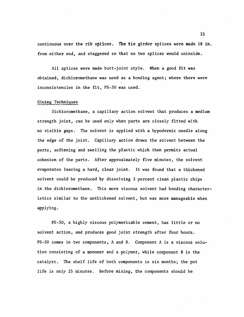

16
allowed to warm to room temperature for 12 to 24 hours Proportions
required to make PS 30 are
Component A 9S grams or 9S cc Component B S grams or S cc
After stirring for two minutes the mixture was applied to the joint
with a 13 gauge needle and 30 cc syringe
Although it is recommended that a V-type joint be used in conjuncshy
tion with PS-30 for maximum strength because of the small thickness of
the parts no V-grooved joints were used during fabrication PS30
was used only to overcome natural nonconformities in fit
Cutting
The plastic sheets were cut to size by a 10-in radial arm saw or
a l2-in table saw with a No 88 plywood blade To avoid handling the
deck plate it was trimmed to size in place using a 7-in Skillsaw with
a plywood blade
The l-12-in strips used for the rib bottoms were cut on the
radial arm saw (Fig 31) Out of 24 strips cut four were determined
to be unsuitable for use and had to be cut again due to a variance in
width For cutting the 3-in rib webs the blade was set at a 14 degree
angle providing the beveled edge needed for a proper fit to the rib
bottoms and the deck plate (Fig 22) Of the first six strips cut this
way three had to be discarded as they were as much as 14 in out of
alignment At this point it was decided to use the l2-in table saw
to ensure a better edge alignment
17
A total of 44 rib sides and 22 rib bottoms were cut To assure
that the ribs would be 12 ft in length when glued together two sides
and one bottom were bundled taped and then measured and trimmed off
in 6-ft lengths with the radial arm saw
Ribs
In order to hold the rib sides at a 14 degree angle while gluing
to the bottoms an eight-foot gluing jig was constructed to adequately
accommodate the 6-ft rib lengths (Fig 32) Foam rubber 12 in thick
by 1-12 in wide was laid on the bottom of the jig to provide a spring-
like effect so that the rib bottom plate would conform to the rib webs
during the gluing process The following step-by-step process was used
in the fabrication of trapezoidal ribs
1 Lay I-l2-in plastic strip on foam rubber pad
2 Place a I-in by l2-in wood strip on top of the plastic
strip
3 Compress foam pad and clamp in place using large C
clamps (Fig 32)
4 Place rib webs along the two edges of the wooden jig on
the rib bottom plate
5 Using small C clamps fasten rib sides to sides of gl~ing
form (Fig 32)
6 Release large C clamps allowing foam rubber pad to gently
push the rib bottom against the rib webs making a firm
contact
18
1 Apply dithloromethane to inside edge of rib using a hyposhy
dermic needle (Fig 33)
8 Wait 30 minutes then release small C c~amps and remove
finished rib from jig
9 Inspect rib for any opening along line and if necessary
reseal with PS-30
Floor Beams
Fabrication of the floor beams consisted of four steps
1 Cutting 8-in by 6-ft strips for web plates
2 Cutting openings in the web plates as shown in Fig 34
to accommodate the continuous ribs
3 Cutting five lIS-in x 2-l2-in by6-ft flange plates
4 Gluing flanges to the web
Some problems were encountered in making the web openings for the
floor beams The sides of the 3-in deep openings were cut with a radial
arm saw while the 1-12 in bottom was cut with a coping saw The same
technique as in gluing the ribs was used to glue the web to the flange
The flange was placed on a foam rubber pad and a series of clamps were
used to form a jig to keep the web upright (Fig 35) Small wedges were
then slipped under the foam pad where needed to provide the proper fit
Gluing was accomplished by applying dichloromethane to both sides of the
web No PS-30 was needed
Assembly of the Orthotropic Deck Model
After the fabrication of all the basic elements of the orthotropic
19
deck model was completed it was extremely important to follow a well shy
planned sequence of assembly steps The protective paper was first
removed from the deck plate and the ribs were placed on the deck in
their proper positions To provide a means of pushing the deck plate up
against the ribs a large foam rubber pad was placed under the deck (Fig
36) The ribs were positioned by using the notched floor beams as
spacers When all ribs were in their proper position weights were
applied at various locations to provide a tight fit Again wedges were
slipped under the pad to help make the deck conform to the ribs All
ribs were checked visually and with a thin feeler gauge for proper connecshy
tion to the deck The ribs were kept tight against the floor beam
notches by means of thin wooden wedges which were manipulated by a 7-ft
pole with a hook on the end
Pursuant a lengthy process of assuring that every piece was
properly positioned and fitted ribs were glued to the deck using
dichloromethane This assembly was left undisturbed for 24 hours after
gluing before removing weights and floor beams Checks were made for
places that were not welded properly and such points were reglued
using PS-30 After the rib plates were spliced at mid span the floor
beams were repositioned over the ribs More filing of floor beam webs
was needed in order to obtain a Eroper fit In the event of some gaps
(116plusmn in) which were too large to bond with PS-30 J small plastic
wedges were inserted prior to gluing In order to keep the highly
viscous PS-30 from pushing the wedges out during application dichloroshy
methane was used to spot-weld the wedges in place before applying PS-30
20
The floor beams were held in place during the welding process by
heavy steel bars lying over the tops of the ribs and clamped to supports
at each end (Fig 37) Weights were placed on top of the beam flange
to help hold it against the ribs The floor beam was then welded to the
ribs and deck plate After all floor beams were in place the deck was
turned over to check the reliability of the welding (Fig 38)
When it was determined that the welding of basic deck elements was
adequate the model was again turned over and the tie girders were added
The inside web of the tie girder was welded to the deck and floor beams
first The outside web was then installed followed by centering the
flange and welding with dichloromethane The total weight of the
finished assembly was approximately 125 pounds
Supports and Loading Beam
The model deck was simply supported on four corners by 2-in by
3-in steel plates (Fig 21) Two of these plates were placed on fixed
rollers (simulating a pinned joint) while the opposite pair was placed on
standard rollers
The loading beam consisted of a 10-ft aluminum H-shape supported
at loading point or points Two weight hangers were provided on each
end of the loading beam Each calibrated weight consisted of a fiveshy
pound chunk of caulking lead During testing a number of weights were
hung from the loading beam to obtain the desired load (Fig 39)
CHAPTER 4
TEST RESULTS
The Computer Model
A discrete element model capable of handing orthotropic plate
problems (18) was used for the analytical part of this investigation
The model (Fig 41) represents the stiffness geometry and support
conditions of an orthotropic plate continuous over flexible floor
beams The -principal features of this method include the representashy
tion of structural members by a physical model of bars an~ springs
which for analysis are grouped into two orthogonal systems of beams
and replacing the differential equations for orthotropic plates by
their finite-difference equivalent The problem then is reduced to
solving a large number of simultaneous equations rather than one complex
differential equation The computer program developed from the above
model permits the stiffness properties of the orthotropic deck and
floor beams to be included on an individual basis -thus resulting in
a more realistic representation of the bridge deck as an equivalent
orthotropic plate The bending stiffness of the plate in the x- and
y-directions and the Poissons ratio effects are represented by elastic
blocks at the nodal points (Fig 42) Support conditions are simushy
lated by elastic springs of appropriate stiffness at each joint while
twisting stiffness is modeled by torsion bars connected to the rigid
bars between elastic nodal blocks
22
Member stiffness and load values are entered in the ~omputer
program by first dividing the slab into increment widths of hand h x y
in the xmiddot and y-directions respectively Figure 43 shows the coordishy
nates of the deck model under investigation A joint is defined as
the intersection of the station lines in each x- and y-direction while
a mesh is understood to be the area surrounded by four jOints Or~hog-
onal flexural stiffnesses D and D are entered on a per unit width x Y
basis The torsional stiffness H is input on a unit width basis for
each mesh its value is determined with the aid of a separate computer
program following the method in reference (2) A listing of this proshy
gram is provided in Appendix ICa) Applied loads are assumed concenshy
trated at each joint therefore a distributed load must be proportioned
among the surrounding joints on a tributary area basis Unyielding
upports are simulated by introducing very stiff springs (500 kin)
at the joints on the support station line Discrete members such
as floor beams and girders can be entered on an individual basis by
giving their total stiffness values A typical computer output is
given in Appendix I(b)
Idealized Sections
The only function of the tie girders was to provide a flexible
support for the floor beams Therefore no attempt was made to properly
scale the tie girders~ as in an actual bridge their span lengths and
cross-sectional dimensions would be much greater ConsequentlYI
theoretical investigations by Chwalla (5) on determining th~ effective
23
width of the deck acting as the top flange of the tie girder could not
be used Instead this effective width was determined experimentally
by measuring girder deflections for several symmetrical loading condishy
tions and computing the required inertia needed to obtain this deflection
The tie girder inertia value was found to be 4434 in4 which corresshy
ponds to an effective deck width of 20 inches
The effective widths of the orthotropic deck plate acting with
a rib and floor beam were computed using the method outlined in the
AISC Design Manual (2) and others (23) It was determined that because
of its narrow width the tie girder would offer little or no rotational
restraint for the floor beams this justified using the full length of
the floor beam as its effective span when computing the effective
width All idealized sections along with corresponding inertia and
stiffness values are shown in Appendix II
Calculated vs Observed Deflections and Strains
(a) Deflections All deflections were corrected to account for
support movements during loading This was done by using a linear
interpolation of the settlements between supports Although a biaxial
stress field exists in the rib plates the use of uniaxial strain
gauges to determine strains at rib bottoms was justified through
experimental observations made by Erzurumlu and Toprac (9) Linearity
checks were made on deflections and strains for all loading conditions
prior to plotting any profiles
computed and measured center floor beam deflections are shown
in Figs 44 through 49 for all loading conditions At this juncture
24
it should be noted that the mathematical model does not account for
shear deformations The deflection due to s~ear was computed for a
lOO-lb load applied at the center of the floor beam and was found to
be 0023 inches If this correction is applied to the computed deflecshy
tions of Fig 44 the correlation between computed and measured
deflections would be very good with the difference reduced to less than
one percent Examination of floor beam deflection curves for other
loading conditions indicates that when the load is not directly over
the floor beam there is closer agreement between computed and measured
values This substantiates the need for a shear deflection correction
on floor bearns as less shear correction would be needed for smaller
floor beam loads It is interesting to note that good agreement exists
between computed and measured deflections at the tie girder as long as
the load is symmetrically located however as Figs 48 and 49 indishy
date a difference of approximately five percent exists when loads are
positioned in the driving lanes Thus the tie girder inertia value
and corresponding effective deck width are dependent among other things
upon the position of the load which is what Chwallas (5) theoretical
investigations indicated
Good agreement exists between experimental and computed deflecshy
tions of the ribs in Section 1-1 (see Fig 211) for the loading condishy
tions shown in Figs 410 through 417 Generally measured deflections
are slightly more than those computed with the difference seldom
exceeding five percent Again shear deflections may account for
25
some of this discrepancy as the difference is usually greater in the
center of the deck or directly under the loading pads Another possishy
ble cause of discrepancy is the localized distortion effect in a rib
produced by the moving together of the deck plate and the bottom rib
flange resultingmiddot in a lowered moment of inertia and section modulus
when a rib is under load In Fig 411 the computed deflection
directly under the load is greater than the measured deflection This
behavior is believed to be caused by the fact that the wheel load is
input as a point load due to the limitation of the mesh size Because
the 6-in long loading pad is centered over a node it cannot theoretishy
cally affect adjoining nodes In actual behavior however the load
is distributed to some extent to the adjoing nodes thus accounting
for the difference between measured and computed deflections on the
adjoining ribs An examination of Fig 417 reveals the same type of
loading condition resulting in the same relationship between computed
and measured deflections The extent of the discrepancy is not great
in this case as the load on each node is only one-half that of Fig
411 Generally when the load is over the floor beam the rib action
is fairly uniform (Figs 410 413 415 and 416) When the load
is in an adjoining panel centered between floor beams (Fig 412)
there is a slight rise in the center rib The decreased magnitude
of the computed deflection again is due to the load being input as a
point load A check of the strains at this point both theoretical
and measured reveals that the bottom fiber of the loaded rib is in
compression In contrast the adjoining rib bottoms are in tension
26
and thus verify the shape of the curve The deflections and strains
for computer coordinate (66) (floor beam bottom) are given in Table I~
Deflections again vary depending on the position of the load with the
greater percentage difference being when the load is near the floor
beam
(b) Strains Overall strains vary anywhere from 1 to 49 percent
with computed values generally higher than measured values The large
discrepancy between computed and measured strains is probably due to
the following causes
1 Instrumentation error
2 Warping of the deck due to uneven support settlements
3 Idealization of the structure as a discrete element
model
4 In the case of ribs the assumption of a uniaxial
stress field in the rib bottoms
The instrumentation error could be as high as ~20 ~inin
and would account for a larger percent difference between computed and
measured values in low ranges Therefore readings less than lOO~inin
would be too small to verify the adequacy of the discrete element comshy
puter pr~gram
The warping effect could also cause plus or minus strain errors
depending o~ the magnitude andlocation of the sUPPQrt s~ttleIlJ~nt$
27
A safe assumption is that the more warping the greater discrepancy
between computed and measured strains As an illustration referring
to Table I the 30 percent difference in loading condition F could
be due to warping because of the unsymmetrical loading in that case
An examination of the support deflections reveals that Gauge No 7
drops 0049 in while the diagonal corner Gauge No 9 drops only 0011
inches This indicates a warping effect and a possible explanation of
the 30 percent discrepancy
While the accuracy of the discrete element model could be
improved by using a finer grid the mesh size chosen was considered
adequate for the purpose of this investigation and prevented excessive
use of computer time Because the theoretical data generated for
deflections and bending moments are average values there will likely
be some differences between experimental and computed values The
errors introduced by assuming a uniaxial stress field in the rib
bottoms would have some influence on the computed versus measured
relationship which would be more apparent when the ribs are heavily
loaded
Computed and measured strains for most loading conditions are
given in Tables II through IX Keeping in mind the previously
mentioned possile sources of error there is generally a good agreeshy
ment bet~een theory and test results It is interesting to note that
when a load is directly over a rib (Tables III and VIII) the computed
strain is considerably greater than measured strain--38 to 49 percent bull ~ ~
28
This can be partly attributed to the load being input as a concentrated
load and partly to the excessive distortions of the rib plate directly
under the load This localized distortion effect was also noted in the
investigation reported in Reference (9) A check of the floor beam
strains near the girder (Table II) Gauge 1-7 indicates there is tension
present at that location Although the strains are too small to be conshy
clusive it indicates the assumption made earlier which stated that
the tie girder offered little or no rotation restraint for the floor
beam was reasonable
It could be concluded that within the limits of the experishy
mental program the orthotropic deck responds as predicted by a discrete
element computer program in the elastic range
1
CHAPTER 5
CONCLUSIONS AND RECOMMENDATIONS
Conclusions
In view of the findings documented in Chapter 4 it may be conclushy
ded that
1 Plastic sheets of acrylic can be used as a modeling material
for the fabrication of orthotropic deck models Ordinary
woodworking tools are effectively used in the deck construcshy
tion thus keeping costs to a minimum
2 Dichloromethane and PS-30 are compatible an~ effectively
simulate welds in steel orthotropic decks when tests are
conducted within the loading range of this investigation
3 Creep effects of plastic do not adversely influence test
results when proper testing procedures are used
4 Indirect models can be constructed from plastic acrylic
material to test structures as complex as orthotropic decks
5 The discrete~element model proposed by Matlock and Panak (18)
is effective in predicting the moments and deflections
along grid lines of multiple panels of orthotropic decks on
flexible supports
30
Recommendations
Future investigations involving orthotropie bridge decks should l
based on this study be concerned with the following
1 A computer program using a finer mesh size should be run
on this model to see if the results would change signifi shy
cantly
2 The deck should be supported on concrete blocks so that
warping would not be a factor in recorded deflections and
strains
3 The box girders should be properly scaled so that a check
on its torsion restraint could be made
4 The model should be extended to a length such that a full
AASHO Highway vehicle could be simulated as a live load
5 Investigations should be conducted on the interaction of
the rib and floor beam by extensively gauging the areas of
intersection
6 Decks using different types of ribs (open biserrated etc)
should be modeled and their response compared with those
obtained from closed rib models
7 Orthotropic decks on flexible supports should be modeled
with steel as a means of checking the ultimate strength of
the system
REFERENCES
1 American Association of State Highway Officials Standard Specifications for Highway Bridges 1965 Washington DC
2 American Insitute of Steel Construction Design Manual for Orthotropic Steel Deck Bridges New York 1963
3 Boussinesq J V Complements ~ une Etude sur la Th~orie de lEquilibre et du Mouvement des Solides Elastique dont Certaines Dimensions Sont Tres Petites par rapporta LAutre Journal de Mathematique Paris 1879
4 Cauchy A L De la Pression dans un System de Points Materiels Exercices de Mathematique Paris 1928
5 Chwalla E Die Formeln zur Berechnung der vollmittragenden Breitediinner Gurt und Rippenplatten Der Stahlbau No 10
1936
6 Cornelius W Die Berechnung der ebener Flachentrag-Werke mit Hilfe der Theorie der orthogonal-anisotropen Platten Der Stahlbau Vol 21 1952
7 Engineering News-Record Californias Orthotropic Bridge Set to Go October 29 1964
8 Engineering News-Record The San Mateo-Hayward Bridge A Fabrishycation Dream June 23 1966
9 Erzurumlu H and 1oprac A A Research on the Deck Elements of the Ammi System Structures Fatigue Research Laboratory Report No P550-12 The University of Texas Austin March 1970
10 Geckeler J W Elastizitatstheorie anisotroper Korper Handbuck der Physik Band VI Berlin 1928
11 Gehring R De Aequationibus Differentialibus Quihus Aequilihrium et Motus Laminae Crystallinae Definitur Berlin 1860
12 Guyon Y Calcul des Ponts Larges ~ Poutres Multiples Solidaris~es par des Entretoises Annales des Ponts et Chaussees No V Septembre-October 1946
13 Hardenherg G J Design of the Superstructure of the Port Mann Bridge1f The Engineering Journal July 1961
14 Hedefine A and Silano L GI Design of the Fremont Bridge ASCE National Structural Engineering Meeting Portland
32
15 Heins C P and Hails R L Behavior of Stiffened Curved Plate Model Journal of the Structural Division Proceedings of the American Society of Civil Engineers Vol 95 No ST-l1 November 1969
16 Huber M T HDie Grundlagen einer rationellen Berechnung der kreuzweise bewehrten Eisenbetonplatten Zeitschrift des Osterreichischen Ingenieur - und Architekten-Vereines Vol 66 No 30 1914
17 Massonnet Ch Methode de Cal cuI des Ponts a Poutres Multiples Tenant Compte de leur Resistance ~ la Torsion Publicashytions International Association for Bridge and Structural Engineering Vol 10 1950
18 Matlock H and Panak J J A Discrete Element Method of Analysis for Orthogonal Slab and Grid Bridge Floor Systems Center for Highway Research Report No 56-25 The University of Texas Austin May 1972
19 Mayer R Die Kurpfalzbrucke uber den Neckar in Mannheimtt Der Stahlbau Nos 6 7 8 1952
20 Naruoka M Okabe T and Hori K An Experimental Study on Model Continuous Beam Bridge with Steel Deck Publications of International Association for Bridge and Structural Engineering Vol 18 1958
21 Pelikan W and Esslinger M Die Stahlfahrbahn-Berechnung and Konstruktion MAN Forschungsheft No7 1957
22 Shields E J Poplar Street Bridge Design and Fabrication Civil Engineering February 1966
23 Troitsky HS Orthotropic Bridges Theory and Design The James F Lincoln Arc Welding Foundation August 1967
24 Troitsky M S and Azad AK Bending and Torsion in Orthoshytropic Deck Box Girder Journal of the Structural Division Proceedings of the American Society of Civil Engineers Vol 98 No ST-9 September 1972
25 Voigt W Lehrbuch der Kristallphysik Leipzig 1910
26 White Richard N Similitude Requirements for Structural Models Conference Preprint No 469 ASCE National Meeting on Structural Engineering Seattle Washington May 1967
-
P
- () ~ -4 X ) -- tQ - 0 -I ftl
rshy ~ r 1gt
-1
C It (
~
~
shyo
Z g
- c o-Z
Ie
CP C
---
-
-n-G ~
0 1tI lt
0
t IfI Z J ()
Z P
I I
I I
I
I I
I i
I
-tshy I I t I ~
I I I I I
~
t ~
I r-shy
1-shy I I I I I I I I I I
I I I I
I I I
-
I
I I I
I I I
I I
Imiddot
-
bull shy0
--tshyI
I po U
Q r---shy 0
I i
~ 0
I
)0
~ omiddot-0 ~ T bull l
l
~LO II
OOlte
middotOOmiddot~middotmiddot---I
GLQ ~olt -rL1
OO~ 00laquo
gt o obull
tf
CNOIN~HIO
0 ~~HM 9middot21middotCJ1~ bullPti Z
JJd 1fO 1nJS 4MJ ~Q dOl H1 14
1 QJO01 d11t19ff
bullIampZ Ie I~ J~fianlt ~11aM flU iD dol 4tU J ~41~ JatlN~
(l~t1n4Ci( -amiddotl1f14 oN1
01 l7Z til
OJ oz z
01 Oll 9
CHWI
L$ C~HN
~ tdl Nt
dVO ~aHM
1g=3HM NaJ t11 -10 4-a~ l 11NO lt middot21middot)~ I
~JJM irtJ ~del erialJ 4211 J ~oJo ~1J
lfLNO ~1(11l1
~=3a1 IN=lfn~J ClJ10 llJltCnlt i3U (1110C odo 11 11lo~
OZltH --ao~ ~~IC d ~NIO~O 1z middot~Id
fa tt a oe 01 ---~l
Z~
01
~Yiq~~ ~a~rAJJlta
~ta ~o J~ ~fd ~
1 ~shy ()
~ 0 Id
lj~t43001~ N~~Ml~Q t+1r+1ML=aca ltofd d
CI 0
H1aq ~OG1-l -10 ~ clta Ia If CO vd ~
1 0
------
N k I
C () n -till J
~-9ca (1001 d) lY bull ltltlIa N~~Mll ltQ~d -
I~ raquo ~
1 ---1-- 0 f 111
)~
c ~aq 2I001-i N~~Ml Haca 7J001d -~Cd ~ C317J 11 ta~d -(f) -io bull ~I2J LV 011d bull
I 1)1 ---shy-PJ----4---+ 0
Q 9
AI
~-lf11 l J
--shy-~---t----- -
j~
0- lIf
--
-~ o
I Imiddot I I I I
I
I I sa I
bull- bull
tEl - - l=~ Abull -C)
bull ~
I II
I I I
I ta I ~ ~~ lar I j Il~ CP e 0
tIbull
~bull ~ -shy
[l ~ 1-1 -T
bull --1 bull bull bull -~ Jl 1 bull -abull ~ I I I I
~I I JQ
Ql I I I I ~ tf of(
Jl ~
tclXll~~4 1IDD~ _ I - r-
if bull(Jill i I
I
I I
I I
II
I
ot
---
-
II
G ~
-
r 0 ~ tgt
0 ~
Z
~
0 tgt r
G 1gt C lti
I I I I
I I
I I I I
I I I
I 1
-- _shy - - I
I I t
t I
I I I
I I I
1 I
o~ P~ t (~ lt1gt1= c~ bull bull Q )l ~ ~ -
i I
I shy
I I I I I
bull bull oa I
~
1Q I I I i 0 I I I I I - I-4
~
I
~amp~faq 2Joo -I -shy -I r J --1-shy I I I
I I I II
I
_L
ED CD agt
)02z[
lQ ()-C0 ~UQ
)
0 ~ It )10 U
-1-
U t J
t -0 0
42
Fig 212 Test Set-Up During Testing
Fig 213 Bridge Used in Deflection Measurements
43
Fig 3 1 Radial Arm Saw Used fo r Cutting Plastic Sheets
Fig 3 2 Gluing Jig and Clamps
44
I
Fig 33 Application of Dichloromethane to Rib Seams
Fig 34 Cutting Openings in Web Plates
45
Fig 35 Jig Used in Gluing Floor Beam Web to Flange
bull Fig 36 Deck Assembly Prior to Gluing
46
Fig 37 Ass emb ly Us ed to Hol d Floor Beam In Place Prior to Gl uing
Fig 38 Turning the Deck Over
( gJ ) 1=3COH JN~r~1-=3 1~-iZJca HOCl-i LNIOr 11dkl z-v middot91j
( qy) ~L~1d I d0211oHJ2IO -10 1aOH LN3H31~ JJ~ZJC(j -tJl-i
x~~~____________~
2
-r
middotat
x 2~ 1 01 ( ~a ~ C lt~ ~I 0 --u
-~ ~
~~ ~ f) middot)(4
D b-
~o
~4 t IU
1)1 G
J
-n I~flt)(~L1J) middotPN ~9H-(i ~
~ I -1 rT nn rrrr1 TTlVf- d)
bull ~ d~Or lID IIU IIJJ LUJ
)Y 0 (01 q ~V C1JC101
0
() shya r --hTIm I 1111 I~
l~ ~ I1II
D -0 -aN 00~O1 ~ tJ4 o~a ~o - c - -I P
ct 10 -~ lti -shy IQ
1
-) ----- _bull -tt -shy-t
-(p
0
~ 0
I)
-~ ~
~ P
~ ~ 61
0
~
~ ampgt p ~ tt Z 4 m ft
r () 0 F
0 ~ 1gt - ~
w r n ( -4-~ 7shy
r 0 Cgt 0bull ~ ()
7 C 0
bull () G to a
C -I Il 0
0
0 tI
r
0-
0 0-
- Q 0 I
0 I ~
0 0 00
I Z z ( r tT ~ lti
~ ~
- 0
( -l -I t -a 7 ( -4
11 r l1
r ()
~C ~---- ~ ~ shy ~ - 0 8~ ~ tIshy -
bullbull 0 1 0 0 lt) 0 r 1t ~ r (
t - -()
L
) P P ~ C)
Z P Jgto
0
p
~ 1 Qshy
~ s
l Z -4 n f)
r l 0 1
G ro P 1_ Q t( l r ttl ( -- ) Z
r (l 1gt
~ ( () Z 0 Q
() 0 0
()
i I
-
~~ -1)
-~
-~
~~ -
-~ ~
-a
-() II
()
U ~
-~ f(0 1gtshyt(J ~~ e w ~o 0
() C)
~ () -()
i I
9 ~
~
~ t1 L --I rt ll
r -
C) 0 1
~ w I_ 0 t
r w (
-- - -Q
Z
r ~ 1gt Q ~ 7 ~
~
1 r IT (
--
o~ I -z ( I It
~
~
~
~ -~
() shy
~ N l 0 () ~ U
LS
G - ~ 1
rshy)
~
$ 1gt
r shyo l -r r f(1
--l )
7
-
0 It 1 r It t - 0 ~ ~
-Z 0
~ I 0 O~ z I (
~ -~ ---] m ~
N ~
ii ~ 0 -ltP shy ()
IT 1 ~
t
)
~
~ -~
lt)
I
shy Gmiddot ~
-
r (J
It
Qrshy-~ t) l ~ ll () () 1
W bulli
rQ
1gtshyi
w~ r ft ( -t - 0 7shy
r ) 1gt ~ middot ) ~ Z
middot ~
n
- 9
-~ -J IT ~ --shy0 Z II-shy
~ n r
-4 )
z N Ol - fl 0
rshy r ~ Igt 0 ~ Z ~ l
~ Sl-() 0
~~ Ot i i
I shy~ a (l
~ 1)( c~ ((
wo u
0 fT shy
t) t) IT 0
~ 8~ 0 -l
(5 I ----I I Z C Z ( I (T
~ ~ ~ 0 ~
I J~ t1 (( --lshyshy( () 1gtshyZ ~ bull
U It
rshy bulltI shy-II =Jesshy ( --
l -I 0 z 8shy 0shy
fl ~
l (
0
rshy(l
r t) 1gt ~ bull ~
z ~
~ Jgtoo
~
~ o I
~ ~
-)l J
~ ~ 0 z
-I
0 tr -p r 11
n Q Z ~shy P ~ ta 0 1- r - r ~ 1gt ~ ( Q1 ~
(~ 0
t -0 C 0
0 fJ
rshy rn (
-~ ~ ~ -I 0 o 0 0 o bull ~ 8~ I I bull i I Z
--
1--shyZ ( I
-~ en ~ ~ ~
1 ~ -J ( -
0 z --
~C-~~O - f1I -~TI ~r
0II (
--- 0 ~ 0 ~l~ Z 0 1
1Q
Ibull
-~~~ I -~~ _1G -() 0
~o S
rshy f1
r C) 1gt 0 ( 0 Z -0
0
--s U C ~ 11 0
9
-l ( ~
-4shyt) z bull
- 0 n
rshy (t1
--l t) Z lQ
-0 -a fQ () r
r 0 ~
~ ( () Z ~
sgt
0 IT -n r IT ( -l
0 Z Z ( -t ff J
6 -I bull ~ S
N
0 0 ii ~
S) p ~ ~ ~ -0 0 6
8 o ~ 0 i I i I
~ ~ -~ U ft C
shy0 z -- - - Cl1
- r~ - lr-
-~ ( 11 0 1gt
to ) -0 C C f3 -t t Cl1 ~ 0
t~ shy 0 ()0 z
r
r ) 1gt ~ f ~ 7shy9 0
~ -J
t
(p ~
0
C
() 0 ~ 08~ o~
i
~ ~ -J shyl 11 ( -t 0 Z bull-~ rshy Il t ~ --- --I-~
() 7shy
N tl 0 P
Q lQ ~ ~ lt)
r ~
r Il (1 WI
r r 0 0 1gt tgt 0 ~ ( ( tgt a Z z 0 0
t ttl
I ~
1 (
o I
~ c ~ 1Q
ltV 0 Q
- ltY-o o 0 I
C
TABL
E I
FLOO
R BE
AM D
EFLE
CTIO
NS
FOR
GAUG
E LO
CATI
ON
1-5
FL
OOR
BEAM
STR
AIN
RE
ADIN
GS
FOR
GAUG
E LO
CATI
ON
1-9
LOAD
iNG
CON
DIT
ION
r
A
B
C
D
E
F
-
Com
po
Mea
s
Com
po
Mea
s
Com
po
Mea
s
Com
po
Mea
s
Com
po
Mea
s
Com
po
Mea
s
Def
lect
ion
(1
-5)
Inch
es
011
4 0
124
013
5 0
151
011
3 0
124
013
2 0
145
011
0 0
116
013
0 o
~42
Com
pute
d M
easu
red
091
0
89
0
91
091
0
95
09
2
iStr
ain
(I
-9)
Mic
roin
ches
17
5 20
6 61
8 53
1 15
7 17
3 44
6 38
0 12
2 13
7 33
8 26
0
Com
pute
d M
easu
red
-shy~-
085
1
16
----_
__
_
__
shy_
_shy
087
1
17
-_
shy
089
ff
13
0
P =
100
LBS
til
--
J
58
TABLE II
STRAIN READINGS FOR LOADING CONDITION A (1
I
~ (1)
cQ
~ 0 0
~
~ (1) +-gts (1) u
GAUGE NUMBER Computed u in in
Measured AI in in
ComEuted Measured
I-I 873 789 111
1-2 679 660 103
1-3 510 495 103
1-4 361 329 110
1-5 229 202 1 13
1-6 - 1-7 -
-- en
Jl 0 - bull
s 0 +-gt u (1)
til
11 3 205 208 099
11-6 202 229 088
11-8 194 199 097
11-9 183 173
-106
11-10 170 147 116
- -g g instruments
P 100 LBS
ji
I
59
TABLE III
STRAIN READINGS LOADING CONDITION B lt
~ (J)
Ql
~ 0 0 ~
~ (J) ~
53 u
Computed Measured Computed GAUGE NUMBER u inin JIJ inin Measured
I-I 599 599 107
~
1-2 486 495 098
shy
1-3 375 379 099
1-4 272 251 108
1-5 176 156 113
1-6 -
1-7 -
r- en
0
r-I ~ -
I
sect r-I ~ U (J)
U)
-11-3 2429 1635 148
11-6 453 593 076
11-8 238 242 098
11-9 202 174 116
11-10 -
Too small and within the range of tolerance of record1ng instruments
Wheel directly over rib P = 100 LBS
60
TABLE IV
STRAIN READINGS FOR LOADING CONDITION C 11
Computed Measured ComEuted GAUGE NUMBER ~ in in AJ inin Measured
I-I 587 500 117
1-2 601 559 108 I
i
I
~ 4)
CQ
ft 0 0 -c u ft G) +J
5 u I
I I
1-3 531 507 105
1-4 377 326 116
1-5 241 190 127
1-6 -
1-7 -
tI)
c c oi
-c
-c
s 0 +J 0 G)
U)
11-3 198 160 122
11-6 196 184 107
11-8 190 154 123
middot11-9 180 133 135
11-10 -------- shy -
Too small and- within the range of tolerance of record~ng instruments
P = 100 LBS
jl
~11~~---~middot
61
TABLE V
STRAIN READINGS LOADING CONDITION D 11
Computed Measured Computed GAUGE NUMBER u inin M inin Measured
I-I 424 397 107
1-2 427 439 097
a (J)
i
~ 1-3 378 389 097 ft 0 0
u 1-4 275 271 101 ft Q) +oJ s (J) 1-5 178 160 111u
1-6 shy
1-7 shy
11-3 341 293 116
~ 11-6 844 760 111 en c -t et J
II~8 832 731 114 t
s 0 11-9 260 220 118
-If +oJ
-0 Q)
CI)
11-10 192 159 121
Too small and within the range of tolerance of record1ng instruments
P = 100 LBS
c
62 ~ bullbullbull ~ - ~~ ~ ~ W bull
TABLE VI
STRAIN READINGS LOADING CONDITION E
Q)
eQ
Jot 0 0 u Jot Q) +Js Q) u
Computed Measured Co~uted GAUGE NUMBER ~ in lin AJ in lin Measured
I-I 435 395 110
1-2 558 514 109
1-3 495 478 104
1middot4 451 431 105
4241-5 380 112
1-6 206 165 125
1-7 -
(I)
c~ cx gti
I
6 ~
+J (J Q)
Cf)
11-3 185 152 122
11 6 196 181 108 bull
11-8 205 175 117
11-9 209 158 132
11 10 - Too small and wi thin the range or to1erance-of recorc1Jng
instruments P = 100 LBS bull
bull
63
TABLE VII
STRAIN READINGS LOADING CONDITION E1 2
Computed Measured C0RPuted GAUGE NUMBER u in I in M inin Measured
I-I 435 380 114
1 2 331 294 113
1-3 243 195 125
~ 1 4 169 138 122ltD co $-I 0 0 1-5 shy u $-I ltD +l 1-6 shy= ltD
u
1-7 shy
11-3 1
185 137 135
11-6 170 152 112 en
0 5 11-8 153 135 113 bull r 11-9 135 112 1200
- +l -0 ltD
Cf) 11-10 shy Too small and within the range of~ tolerance ofrecording
instruments P = 100 LBS
I
64 ooo _~~ _ bull
TABLE VIII
STRAIN READINGS LOADING CONDITION F
Computed Measured COIDEuted GAUGE NUMBER ~ inin~ ILl in lin Measured
I-I 317 265 120
1-2 388 346 112
1-3 349 331 105~ CD
bull cl
~ 0 0 1-4 313 292 107
14 ~
~ CD 1-5 282 243 116sCD u
1-6 shy
1-7 shy
11-3 309 357 087
~ 11-6 1343 975 138en I 0
c J
14 11-8 337 412 082 I
14
r 0 11-9 339 382 089 0 CD
CI)
11-10 1349 907 149
Too small and within the range of to1erance-or-recora1ng instruments
Load directly over rib P = 100 LBS
65
TABLE IX
STRAIN READINGS LOADING CONDITION F1
-Computed Measured Co~uted
GAUGE NUMBER ~ in lin AI in lin Measured
I-I 317 253 125
1-2 250 206 middot121
~ 1-3 191 146 131 (I)
al
ft 0 0 1-4 shy 11
tI
ft (I) 1-5 shys (I)
u
1-6 shy1-7 shy
11-3 309 331 093
U)
c II-6 197 180 109OM rt - 11
t 11-8 169 140 12111
s 0
OM 11-9 147 112 131CJ (I)
tI)
11-10 shy Too small and within the range of tolerance- of recordLng
instruments P = 100 LBS
- ~~ - - -~~ bullbull gt~~bullbull - ~
SDNI1SI1 ~DO~d ~31ndWOJ
I XION3ddV
67 ~ ~ ~ bull ~ ~ _~ a bull- ~
I(a) PROGRAM USED TO DETERMINE THE TORSIONAL RIGIDITY
JIDI 8-DIP11I O A IlIBCDO 1101
I I RIM THIS PROGRAII FIOS THE TOaSIGIIAL RlalDITY POil ORTlIOllIOmiddot I 11M PIC DICKS WITH fRAPIZOIDIL RSBS 3 RD II-THleDUS 0 tHE DICJCPLAtS I 6
IUQIJ TbullbullTHJCKIIUS O~ THB alB PLATa RDI A-WIDTH 0 TId IlIB ca) Rill la-SPACIIII or TRS RIBS (I
1aUDa DECK bull aIR H8-LH or 0N8 SIDI OF A RIB e-WIItTII 0 tal BASS or tHamp 81B 10 8M s-NODULUS 0 ILAITICITY I O-GDULUS O RIGIDifY S-ACTUAL SPACteO FLOOR 8EAMS 15 READ tlT8AIalWI_bullbull8aGS 80 u-eeHe+ 30 AlaquoAl8~H 0 K-CbullbullA-CtU(AItlbullbull pbullbull- 44 PRIWT -tHE tORSIONAL STII II CK-I--IP so 1CTImiddot3186e 1(Te~fl)middot3YO 10 LI(middotAI+8-CA1bullbulliB~I-CRImiddotAI~3CSImiddot8))OLI--H-CA-+AI--bullbull-aRI-AI-3 100 LLI~~CAI8Le)
10110 c(~a(AI) ce(~e(AJ-~AI)middotlaquo bullbullbullBI)CAIbullbullraquo)C8lC8A)
130 V-middotJtZImiddotfAI-C CAI+CI -(1~16I1-8 Vbullbull(ampI~A)middot3C(EImiddot(AIBLmiddot1150 V3eCLmiddotftlCAI)middota(IRI(H~A-CCI-bullbullCICbullbullCmiddotala160 v-vcveV3) 171 V-V I PRIIIT -Ha TORSI8IIAL RIIUCfIOactoR ISmiddotJV 110 HbullbullbullSC(Vbullbullbullbull)CA+Bl)) S PRIMT-IKE fOBSIOaAL RIGIDITY IS ca-I-I-bullbull 300 DAtA 115bullbull0e3bullbull 3bullbull 3bullbull 30311~19336bull bullbull9 DID
READY ItUN
AX SOPDI 33 fHa TORSIOIIAL ItJr-as II (Kmiddot middot) 19711 THZ TORSIONAL RIDUctlOM ActOR IS O1681~2 THE TORSIaAL RIGIDITY IS (XmiddotI-8IN 151906
il
68
I
Ieb) PROGRAM USED TO COMPUTE DEFLECTIONS AND MOMENTS
~R08 I LOAI) cobullbulllfttr- middot-middotnNE jHit(-lilrTifCNTEIt 0 OIctC Loio- bullbullbull lei
rAil I COttTrtOL DATA- - ---------------
__--y flkl NBIIt-_ -__ bull 3 I-
HOLO RO IRCpoundDtfC PR08 CI-HLt -0 bull - i ~I - HUtt CIRDS-UIJUT TftllltOI[[- I J ~ 4 __t bull
- rI8[ 2~ CGHSTDTrshy
NUM8pound1t 0 tNtItpoundENfS tN x middotDtrtpoundCTlormiddot middotxmiddotmiddotmiddotmiddot middotmiddotmiddotmiddotmiddotmiddot middotmiddotmiddot_middotmiddot middotmiddot-middot middotmiddotmiddot_middot-- middotmiddot -middot-middot--middotmiddotmiddot-----2 ----- middotmiddot-NUits-or-YNcRfMENfs IN dIRECTION My z
INCREMpoundNTLNGTH INX OmiddotIItfImiddot ttx - -- -- -middot-- -i-~middotjmiddotiabullbullbull shyINCItpoundIitNT LENGtH IN ot_poundCTtONmiddotH middotmiddotmiddot middotmiddotmiddot-middot middotmiddot-middotmiddot-middot- -middotmiddotmiddot-~ middotbullbullImiddot+middot
- ---- pbISS-ONS___lTro--- - I SLI8 TICtCNESS cfmiddotaimiddotmiddotmiddotmiddotiiilwmiddotptCljA[-M(hpoundN-fmiddottSmiddotCofllPUfeifmiddot----middot---------
--I spte lIEfJ ti_ tmiddot ncrIL STHSS _ -_-- __ _-_shy
rilL J JOINTmiddotSTIFFNESSINOlOIOmiddotDIT shy
- - - - ---_ JlY -middot middotmiddotmiddot-u_middot -_middot -- ----T----shytn OXmiddot TltU JOINT JOTNT
emiddotmiddotmiddot bull 1 2 middotmiddotmiddotT~-middotmiddot-rlr-Df-- ffJS-C 0middotmiddot-middot-middotmiddot---middot- --middot1---------middot --1middot------ -- -1 o 0bull middotmiddotImiddotmiddotIIJlr-IC-4poundr -1-~ --- ---- -0)---- - -- -- -_---- -----shy
D 24 II 24 -11ltl2 -496tGI -I -0 -I -Ibull __d -6-11middot-- 1 ----------- -----middotmiddotmiddotbullbullZ1--D----- -I ---------- shyJ -12-1 -middot-12-middotD~-middot----middotmiddotr----middot-middotmiddotmiddot---middotr-G7middotI-middot-I _ ---___-_ D II 12 II -1 -a 12fpound+G -0 -0 -0 111 r ---- bull-- --middotmiddot-middot-middot--middot-----lI7R middotT-middot--middotmiddot ----------bull(-- shy1 2~ rr-middot2~ middot-0-----middot--------middot--middot --middotmiddotmiddot-middot middot171poundbullbull[1middot-middotmiddot __middotmiddotmiddotmiddotmiddotmiddot -----bullbull------ --------shybull D I 2 -0 -D -a lffEf -I -I
-TI--TmiddotII-y-l~-middot----T-middot--middot --------------r7~bull - ---- ------ shy_ -- --- ---1 -I ------- --- - ---------T-n-shy
12 bull 12 1 -I -D -I -I -0 bullbull11112middot-ii-middot-z -0 _o-r bullbullbull bull~- ~ jbullbull bullbullbull
middotmiddot-ftmiddot middotmiddottt11 2O~ middot-a 0 ~ 0 -0--- - - - 112 _ - ----_ -__ - ----- --~- -- - -- _---- --~ -shy
fllEmiddot ~ middot JOIN SfI rsSAND LO AO 0 If- CONTlfmiddot-middot-middot-middot-----middot- middot ------------_____
--Iof middot_ltu middot Itbull it ~=~~t~~= ~~ ~ --J(-JOINT JOfNf
0 pound
-rAIL-middot----S1fSrl1NISStJIfImiddot--middot
middotmiddotlto -- TRU MESH -~poundSf
___J___ JI~_~]~ 2~_~ 19pound+IIJ
- raIL middot6~-middotlfjitmiddotmiddotSTlNpoundSS J ATA --~- - -- ---~ -- - ----shy
FROM fARO ---IAft BAitmiddot
n
---__----shy fI1 JSIY
--
__ __
69 l(b) PROGRAM USED TO COMPUTE DEFLECTIONS AND MOMENTS (Cont)
NONE
---------------------------------- shyraBLE 7 MULTIPLE LoaD OaTamp
FRO- lTIfRO--------- ---- ---- ----------- ----- shy Gil ~
JOt T JOINT
--- r-middotmiddot-f--------- -Iooa-II
_ --_ -- ----------~-----
---- ------------- --_------ _ _ ------------~----- ------_----shy
---1
ItOltaM SLag middotOpoundLDCI( -- -[NaUS - middot-middot--------middotmiddot-ltrfSlOijmiddotflffmiddot-O~middot-(jmiddot-69----IfaXIN~- -PTAOTlopIC OECI( iiiI 1973
LiSTie ORTHOTROPIC OEC( --------- -- -------- ~ -
I ------ ~- ----------shy
IItOB (COT ---j--- 0-=-IO=--C-ON=D=I=T=~~middotN---a=-_-9Neuro=_==HEJ _~o~D J_~_Jl~rIt~_F_)~c~ _l_~~()_u_J_M_ ___________
-------- --- _-__------------------------------__--_-------------shy-rAlIlE a USOCl
Staa MOMENTS aRE PElt UNtTMIlTH--middot------------------------------- shymiddot--~ara opoundNfS-i-RE TOTAL P~~ REa
X TWISTING MOMENT bull - TWISTING M(tEltT--middotmiddot----------middot---------------middot----- shy~- 8a aNGLES aRE COCICWYSEmiddotmiddot -~-
SLa x SLas - - --~-~- S( A-B ---(I~GESf- -- 9pound--- ~----------MOM- 0--middotmiddot- x ------ftttINctal xTO--shy8EA x 8poundIM Y TWISTING ~lA8 lARGEST s~
DrIP -- -OMENT-- MOpound --OMtff -OpoundT- - - OENT RpoundampCftON--------shy--~ - -~ ----- ------ - -- ------ shy-~--yen------~ -~-
bull -DIOE-I -211amppound-20 1Damppound-16 1214pound-0 124-O -40 ZSadE-aZ --- _ -6215E-15 3232pound-13 -- ----~ ---------- -------- shyr r~---2S65E-O middot 229I1E-0amp I ampE-13- _middot pound-06- - 9--middot------ shy
1~6~ D I - 2- -~ a06E- 358E-O GE-16 ~r9IE-6-2~209~6 - ~
- - - 10 UE-G 2 j middot3pound-1 1466E-OII 13SE-02 ft- middotr~--6 Z26E-0 3gE-O amp
1133E-2 -- I --Z-6-67E- -695E08
- -- fO SSpoundmiddot2 z4 -59~- 36 bullbullE-08--- - --- --- - - ---1061 pound-a 2
-------- -6167pound-1---1695pound-08 1085E-D2
- 2tt -6Z26pound-I - 3 ca-olt ~~ ------ ~ --1I31E-02 -516pound-1 ~5amp~~-UI - - -- -- 11 3fE -02
11- z~middot- D6E-t_-- 3S8E-D
a - - - 14IE-6 IS2E-d 937t~-07 -ijij O O~ - ~--- --- -- -- - ------ ---------- shyI E-16-2~ 6a9E-D7-2IIr~pound-7-2 9- I o Zbullbull35pound-16-71S1E-01 7 -01 -3-- crshyD----middot----------- shy2835E-16 3334E-14 361-18 -G ma ----- -- -shyO - 72~-a7( pound-07 --~ 3---0------- shy
_d bull 118-16 6041-07 2104E-a--29-~----o - - -~--------------
2815pound-1 -9112~-Ol 9JfIE-01 i44 d bull O ---------- ----------------- shy~ __bullbull-Cbullbull ~-ua ccipound-6 ~ I
IDI6E-D2 a n ---Z-216Jpound--4- 229iiE-~a I f~-16-3133Ea6 --- pound---- --r-bullbull
-----~------ ----726pound-03 - It ----- --- --------------------- ------ ---------- shy
ii
1300N dO S3Il~3dO~d SS3NddI1S
II XION3ddV
71
lt
12000 --middot--middot-- l~ fb ~PAcJ6 (j ~00 lb 00_
~~
~ FhshyN 1-- II II
~()
0 lIZ 12amp di
1fJ J 2 1r
IDfAlleO 5fCTON
L_~middot_90J ~
Aeamp ALItI) DI5TANGfXIV) A)((t) A)(f(n4) ( InA) 1A~L (In)
DE-C~ PLA1Eshy 2500 Oo~Z5 0 I~ OrxPJ7 Ooob2 ooJ~o
~f WampfS L lob 1F~40 J1(01 1 amp111 0middot174amp ~ eq2o 1---shy
~I[ ampoTTO~5 0274 ~oqAamp ob4CJ Z (1edJ 00001 2 middotftJZt7 c II2DEe W~ J Zooo 4 i~ampo b 2gt0 ~03t fOIft1f1~ 44middot11 (1l2D~rz PLAN6~S Of~lamp tgt t610 ~o7o 2amp t~tJ 00000 Z~middotJ~1
~ 7 Mz~ 14fO~12 - - 711070 -----~
I 1~ A~l middotl~ol0- (~tllr7(1 f)1)fJ 1-010 bull ~11J1
1 44 ~4 ft ~ilffNt~~ pound (~~LX44~) bull flAfeJ10middot It_tnt
fie nmiddot 11 E ~ 2DE fl ~T I r roN eeurogtgt
-~gt
U I ~L0 middot~~ s Ou1 qbLmiddot~-IL3middotlcemiddot
amp( LJlJ rA~1 e) fLea degfe WIYl
ILQ1~
Q1b o~
--shy0000
-QtbO~
tJO)L 9ltlt lJ
LJ~middotImiddotc)fL~
L91I
t J I~
ltJ~middotO
1 _shy~---
dJN1 d Holl
LOb or
I)J 00
(tLAI ) J~V+1
0t1J ll
1deg00
(U) 1
1O~q
of 00
(LA I) x ~
CJOb
c( r 0
(tU1) x~
ocgzft
tilJ())OmiddotO
LU) X NV1Cta
ltd9t7O -------
Cd~ -shy
V11c =3 111 dtJ3a
~u) V3~t4 - _-shy
r1 J~OO
--~-- ------------tl-shy---- f~1I t ~ L----------r-~---_J )ampItZ
73
J2A~H
l to
l d
-N ~
)(
10 E~L ED CbtC 1IoN
~ Ieampoj
lI~Lrb=====~ 111 I~
-g lIO
111 2s
1
DI~ANCf A2Eb(lrl1) 1 (t~4-)A~(rf) A~1 (In4) l+Ax(ln 40)X(m)
oo~13ooCo2amp 000(01 OOO~ODpoundG~ PLATr 1 ~amp fP o006f
w~e A 1Zampo4je~O amp~~siooo 2 2 ~AtqiloV~
Z S~6S 00004 20~4e8eoQ4b4F-LAN 6IE OSi~ b ifgt7
L 4~So~2 bCOfgt wmiddot7Egti -~ampe~4 -
10 ~ 4 ~ou (2 6~OX2 S~4J2 4~ ~o(o - 1 027
1 Z1 Z b 4
Flooe erA~ ~1ffNtegt~ cl - (~14-K27Zfraquo= o14e~o~ ~_Inf
rG n- ~ ampXTf rLi 02 F-ooe ~E-A ~ ~1 prN~SS bull
I
LAI JILoo 0 UI-~ ~ shy
Cib~f~ ~i~~ ~ (J-~I Xc ~ t
--UL b L ~ A J1) Imiddot~ lti lt1 l)Itt Q
Jtn -1 ~1 t~ (Ov IA~b~) 1~ ~~~N-I~ ult=
1 ) I 011 - elLA 1 -VLt1)O -1Loz amp
~(llteLoX~ca z f ) -tLo b OUt
tLO(j --~bo ftCl-hcSZ J ~ bebl ~ PJrLQo 00000 ~JLcao ot9Zo ~bo~ bOo Yi 0 LLod ctllZ)
ctQbif fq~z0 VdegVbO qbgso ltbta middot I b~ce 0 I
lt 93 A I ~l-a
11000 01000 rca-ooo ~btoo cvqoo bbLo ~Jv1d ~1~a
(UI) Jx~tI (UI) 1 (t-II ) 11)(~ (itAJ) X1 (tAl) X
~NVJla (zut) V=Jatl I
x
b~middot~ I J l