Embed Size (px)
Citation preview
International Journal of Scientific & Engineering Research Volume 12, Issue 4, April-2021 858
ISSN 2229-5518
IJSER © 2021
http://www.ijser.org
Response of Railway Steel Bridges to Rail and Wheel Defects
Hanan H. Eltobgy, Ahmed Abdel Moamen Khalil, Emad E. Darwish, Mohamed Saber
Abstract— This paper aims to investigate the structural behaviour of railway steel bridges due to track defects, such as ab-normal rail or wheel surfaces, rail corrugation, rail wear or breakage, as well as wheel flats. The dynamic models were es-tablished using the application of the finite element software ABAQUS to simulate the structure as a train-track-bridge (TTB) interaction model. Benha's railway steel-truss-bridge was used in this study. The part simulated of the bridge's super-structure consisted of 2 spans, in total lengths of 124.8 meters. The train runs through open deck floor (i.e., non-ballasted track). The track is fixed directly to the bridge stringers. The FEMs in the TTB category were established to study the effect of rail defects on the bridge’s elements response (acceleration and strains) and to predict the dynamic amplification factors. Results obtained from the TTB models, related to the simulation of track defects were compared against those mentioned in both Euro and UIC codes. The response for all defects inherent with the dynamic amplification increased by 10% and 20% for the cross girders and stringers, respectively. Defected Track had a significant effect on the bridge acceleration, displace-ment, and strains. FEM results exceeded the allowable limit proposed by the international codes.
INDEX TERMS— STEEL BRIDGES, TRAIN-TRACK-BRIDGE, DYNAMIC AMPLIFICATION FACTOR, RAIL CORRUGATION, WEAR, WHEEL FLAT.
—————————— ——————————
1 INTRODUCTION
ailway bridges are considered critical elements of any railway network. The railway track on the bridge deck was subdivided into three categories: Open Bridge Deck,
Ballasted Deck Bridge, and Direct Fixation Deck [1]. Tracks have a significant role in the railway system as their defects are the most frequent cause of train derailments; in addition to their direct impact on the bridge structural behaviour due to the train-track-bridge (TTB) interaction phenomenon. TTB interaction phenomenon has very prominent role on the bridge’s response. The dynamic impact on the structural ele-ments of the bridge resulted from the train speed, produces abnormal behaviour due to rail defects, thus, directly influ-ences the working status and the bridge service life. On the other hand, the unexpected behaviour of bridge structure due to track defects affects in turn the running safety and stability of trains movement over bridges. Therefore, the structural behaviour of the TTB system associated with track defects rep-resents a fundamental problem that requisite careful consider-ation in the design of bridges. Thus, it has become a mandato-ry to carry out extensive studies on the dynamic interaction along with the train and bridge systems. In view of that, it was necessary to take into consideration the influence of track de-
fects on the bridge’s response in simulating the railway track structures inherent with the TTB interaction phenomena. The track’s random irregularity has remarkable effect on the TTB dynamic interaction, especially in the high-speed operation. The existing track random irregularity should be considered in the simulation of the dynamic TTB interactions [2].
The track irregularities can be analysed in the railway bridge design through the dynamic amplification factor equa-tions described in international union code of railway UIC 776-1R [3] and European code EN 1991-2 [4].
The track irregularities included in the dynamic amplifica-
tion factor were assumed as a vertical dip 2mm, and 6mm ex-isting in the track over lengths of 1.0m, and 3.0m, respectively, under unsprung mass of 2t per axle [5]. The dynamic amplifi-cation is usually aggravated with low quality railway tracks and the effect of track irregularity of various wavelengths triggered obvious changes in the bridge fundamental frequen-cy occurred during train passages [6]-[8]. Furthermore, the shorter wavelengths represented important factors for safety analyses (wheel-rail forces) and structural assessment, while longer wavelengths related more to the vehicle ride quality [9]. The dynamic amplification at critical speed was found to be approximately 2.5 times larger compared with those values recommended by codes [10]. Random vertical track irregulari-ties contributed to high frequency oscillations with large am-plitudes in vertical accelerations of the composite (steel - con-crete) bridge Marian [11]. Local rail and wheel defects pro-duced large amplitude excitations compared to smooth track. Type of rail defect has a major impact on vibration levels [12]. Wheel/rail irregularities such as spalling, rail corrugation, wheel out of roundness, and flat spots could significantly in-crease the dynamic effect, particularly at high-speed [13, 14]. The track-short defects such as loose fishplate bolts as well as
R
——————————————
Hanan H. Eltobgy, Associate Professor Steel Structures and Bridges, Civil
Eng. Department, Faculty of Engineering, Shoubra, Benha University,
Egypt. E-mail: [email protected]
Ahmed Abdel Moamen Khalil, Associate Professor, Railway Engineering
Civil Eng. Department, Faculty of Engineering, Shoubra, Benha University,
Egypt. E-mail: [email protected].
Emad Darwish, Lecturer, Civil Eng. Department, Faculty of Engineering,
Shoubra, Benha University, Egypt. E-mail: [email protected]
Mohamed Saber, Department of Structural Engineering, Egyptian Company
for Cairo Metro (ECM), Cairo, Egypt. E-mail:
IJSER
International Journal of Scientific & Engineering Research Volume 12, Issue 4, April-2021 859
ISSN 2229-5518
IJSER © 2021
http://www.ijser.org
the contact between fishplates and the rail head produced large contact force variation [15]. Track spectrums as de-scribed by the power spectral density (PSD) are commonly used to generate the random track irregularities [16]. [17] stud-ied structural behaviour of railway steel bridges due to track defects. [18] investigated the behaviour of steel railway bridg-es under the effect defected rail welds.
The current study meant to investigate the structural be-
haviour of railway steel bridges due to the most critical track defects liable to produce dynamic effect resulting from the rolling contact between wheel and rail. These defects as identi-fied by [5], include rail corrugation, excessive rail wear, rail breakage, worn wheel (flats or spots), and defects of welded or jointed rail. The study used the finite element program ABAQUS [19] taking into consideration the TTB interaction phenomenon. Regarding the simulation of the interaction be-tween train and bogies suspension system, the train car body and their bogies were modelled as rigid beams [6]. Bogies’ masses and train car body were replicated as mass elements, including the translational and rotational inertial properties of each, foucusing in the middle point of the rigid elements. The suspension systems were modelled as spring-dashpot assem-bly.
2 DESCRIPTION OF BRIDGE
Bridge: Benha Bridge is one of the steel rail-way bridges that
has been built in Egypt since 1965, located on Damietta branch
of the Nile River at 46.290 km on Cairo-Alexandria railway
track as defined by the Egyptian National Railway Authority,
ENR. The bridge has a total length of 320m divided into five
bays. Four bays consist of two continuous spans and a simply
supported middle bay swing span. This work focuses on the
continuous spans at the end of the bridge (62.4 m). The
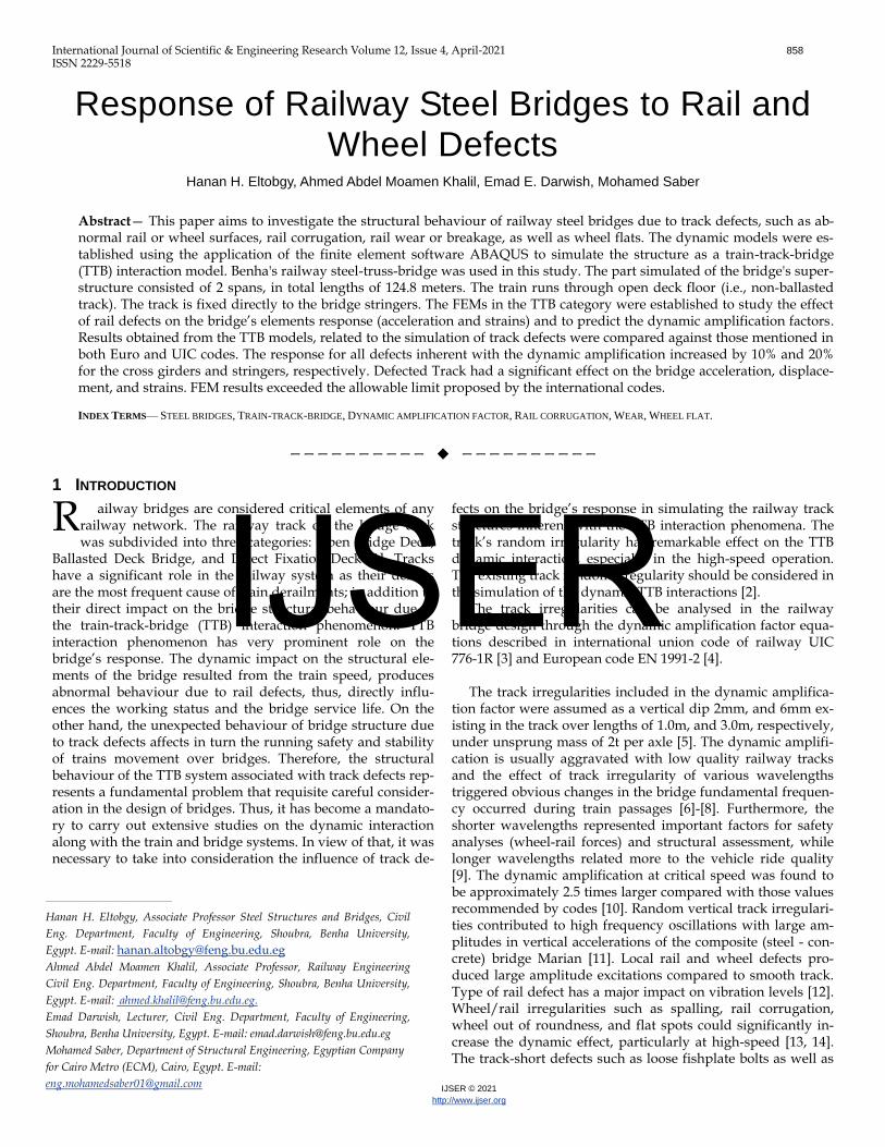
structural system of Benha railway bridge is drawn in figs.1- 3.
The substructure of the bridge consists of seven reinforced
concrete supports (Five piers inside the Nile and two
abutments on both sides). The bridge superstructure is made
of warren trusses assembled by rivets with constant depth of
8.0 m, and with upper and lower bracing system. The distance
between main trusses is 9.15 m. The bridge also has a
transversal cross-sectional portal frames arranged every 6.3m.
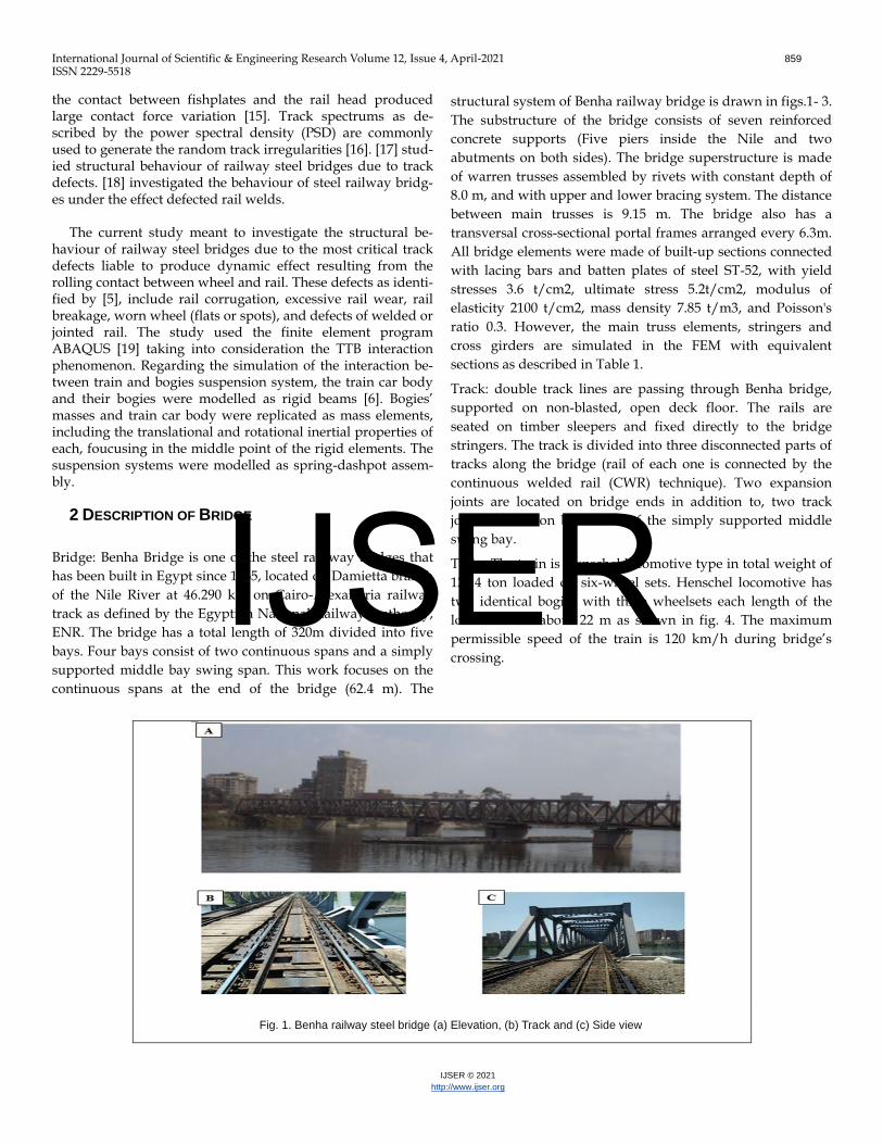
All bridge elements were made of built-up sections connected
with lacing bars and batten plates of steel ST-52, with yield
stresses 3.6 t/cm2, ultimate stress 5.2t/cm2, modulus of
elasticity 2100 t/cm2, mass density 7.85 t/m3, and Poisson's
ratio 0.3. However, the main truss elements, stringers and
cross girders are simulated in the FEM with equivalent
sections as described in Table 1.
Track: double track lines are passing through Benha bridge,
supported on non-blasted, open deck floor. The rails are
seated on timber sleepers and fixed directly to the bridge
stringers. The track is divided into three disconnected parts of
tracks along the bridge (rail of each one is connected by the
continuous welded rail (CWR) technique). Two expansion
joints are located on bridge ends in addition to, two track
joints located on both ends of the simply supported middle
swing bay.
Train: The train is Henschel locomotive type in total weight of
128.4 ton loaded on six-wheel sets. Henschel locomotive has
two identical bogies with three wheelsets each length of the
locomotive is about 22 m as shown in fig. 4. The maximum
permissible speed of the train is 120 km/h during bridge’s
crossing.
Fig. 1. Benha railway steel bridge (a) Elevation, (b) Track and (c) Side view
IJSER
International Journal of Scientific & Engineering Research Volume 12, Issue 4, April-2021 860
ISSN 2229-5518
IJSER © 2021
http://www.ijser.org
Fig. 2. Benha railway steel bridge overall elevation
Fig. 3. Benha railway steel bridge cross sections and statical system
TABLE 1
STEEL SECTION PROFILES BASED ON BRIDGE DESIGN DRAWINGS
Section Profile Bft Bfb Tft Tfb dw tw PROFILE
XG-L I-Section 350 350 40 40 1100 20
XG-U I-Section 280 280 25 25 550 12
STR I-Section 250 250 25 25 850 10
BC1 2C-[RHS] 550 550 6 6 500 14
BC2 2C-[RHS] 550 550 6 6 500 36
BC3 2C-[RHS] 550 550 6 6 500 30
UC1 2C-[RHS] 550 550 10 10 500 26
UC2 2C-[RHS] 550 550 15 15 500 15
UC3 2C-[RHS] 550 550 10 10 500 16
VER I-Section 300 300 25 25 500 11
D1 I-Section 400 400 45 45 500 20
D2 2C-[RHS] 450 450 13 13 400 28
D3 2C-[RHS] 450 450 10 10 400 18
D4 2C-[RHS] 450 450 6 6 400 12
UBR 2C-[RHS] 160 160 8 8 400 4
LBR 2L-[TS] 125 -- 12 -- 140 25
SBR L-Section 100 -- 10 -- 100 10
IJSER
International Journal of Scientific & Engineering Research Volume 12, Issue 4, April-2021 861
ISSN 2229-5518
IJSER © 2021
http://www.ijser.org
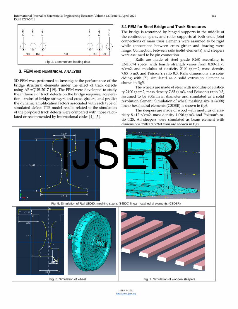
Fig. 2. Locomotives loading data
3. FEM AND NUMERICAL ANALYSIS
3D FEM was performed to investigate the performance of the bridge structural elements under the effect of track defects using ABAQUS 2017 [19]. The FEM were developed to study the influence of track defects on the bridge response, accelera-tion, strains of bridge stringers and cross girders, and predict the dynamic amplification factors associated with each type of simulated defect. TTB model results related to the simulation of the proposed track defects were compared with those calcu-lated or recommended by international codes [4], [5].
3.1 FEM for Steel Bridge and Track Structures
The bridge is restrained by hinged supports in the middle of the continuous spans, and roller supports at both ends. Joint connections of main truss elements were assumed to be rigid while connections between cross girder and bracing were hinge. Connection between rails (solid elements) and sleepers were assumed to be pin connection.
Rails are made of steel grade R260 according to EN13674 specs, with tensile strength varies from 8.80-11.75 t/cm2, and modulus of elasticity 2100 t/cm2, mass density 7.85 t/m3, and Poisson's ratio 0.3. Rails dimensions are coin-ciding with [5], simulated as a solid extrusion element as shown in fig5.
The wheels are made of steel with modulus of elastici-ty 2100 t/cm2, mass density 7.85 t/m3, and Poisson's ratio 0.3, assumed to be 800mm in diameter and simulated as a solid revolution element. Simulation of wheel meshing size is (4608) linear hexahedral elements (C3D8R) is shown in fig6.
The sleepers are made of wood with modulus of elas-ticity 8.412 t/cm2, mass density 1.096 t/m3, and Poisson's ra-tio 0.25. All sleepers were simulated as beam element with dimensions 250x150x2600mm are shown in fig7.
Fig. 5. Simulation of Rail UIC60, meshing size is (34500) linear hexahedral elements (C3D8R)
Fig. 6. Simulation of wheel Fig. 7. Simulation of wooden sleepers
IJSER
International Journal of Scientific & Engineering Research Volume 12, Issue 4, April-2021 862
ISSN 2229-5518
IJSER © 2021
http://www.ijser.org
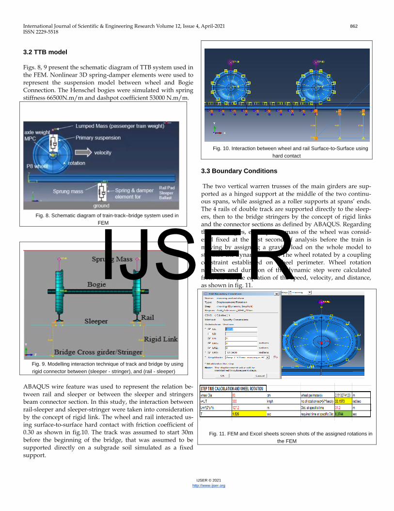
3.2 TTB model
Figs. 8, 9 present the schematic diagram of TTB system used in the FEM. Nonlinear 3D spring-damper elements were used to represent the suspension model between wheel and Bogie Connection. The Henschel bogies were simulated with spring stiffness 66500N.m/m and dashpot coefficient 53000 N.m/m.
Fig. 8. Schematic diagram of train-track–bridge system used in
FEM
ABAQUS wire feature was used to represent the relation be-tween rail and sleeper or between the sleeper and stringers beam connector section. In this study, the interaction between rail-sleeper and sleeper-stringer were taken into consideration by the concept of rigid link. The wheel and rail interacted us-ing surface-to-surface hard contact with friction coefficient of 0.30 as shown in fig.10. The track was assumed to start 30m before the beginning of the bridge, that was assumed to be supported directly on a subgrade soil simulated as a fixed support.
Fig. 10. Interaction between wheel and rail Surface-to-Surface using
hard contact
3.3 Boundary Conditions
The two vertical warren trusses of the main girders are sup-ported as a hinged support at the middle of the two continu-ous spans, while assigned as a roller supports at spans’ ends. The 4 rails of double track are supported directly to the sleep-ers, then to the bridge stringers by the concept of rigid links and the connector sections as defined by ABAQUS. Regarding the train bogies, each sprung mass of the wheel was consid-ered fixed at the first second of analysis before the train is moving by assigning a gravity load on the whole model to stabilize the dynamic model. The wheel rotated by a coupling constraint established on wheel perimeter. Wheel rotation numbers and duration of the dynamic step were calculated from the simple equation of the speed, velocity, and distance, as shown in fig. 11.
Fig. 11. FEM and Excel sheets screen shots of the assigned rotations in
the FEM
Fig. 9. Modelling interaction technique of track and bridge by using
rigid connector between (sleeper - stringer), and (rail - sleeper)
IJSER
International Journal of Scientific & Engineering Research Volume 12, Issue 4, April-2021 863
ISSN 2229-5518
IJSER © 2021
http://www.ijser.org
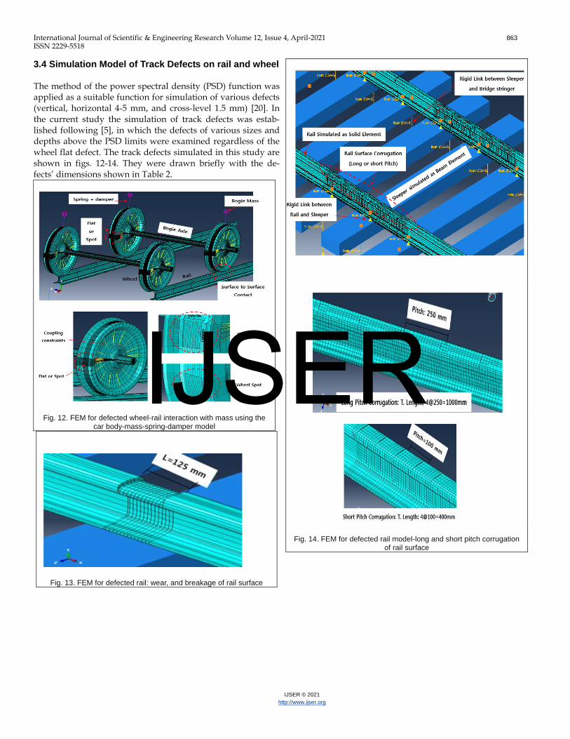
3.4 Simulation Model of Track Defects on rail and wheel
The method of the power spectral density (PSD) function was applied as a suitable function for simulation of various defects (vertical, horizontal 4-5 mm, and cross-level 1.5 mm) [20]. In the current study the simulation of track defects was estab-lished following [5], in which the defects of various sizes and depths above the PSD limits were examined regardless of the wheel flat defect. The track defects simulated in this study are shown in figs. 12-14. They were drawn briefly with the de-fects’ dimensions shown in Table 2.
Fig. 13. FEM for defected rail: wear, and breakage of rail surface
Fig. 14. FEM for defected rail model-long and short pitch corrugation of rail surface
Fig. 12. FEM for defected wheel-rail interaction with mass using the car body-mass-spring-damper model
IJSER
International Journal of Scientific & Engineering Research Volume 12, Issue 4, April-2021 864
ISSN 2229-5518
IJSER © 2021
http://www.ijser.org
4. VALIDATION OF THE TTB MODEL
Dynamic analysis was established to determine the vertical acceleration and dynamic response of the displacement (dy-namic factor). The dynamic model of TTB was simulated by considering a weld defect as a vertical dip (step-up) 7.5mm on the welded rail joint near mid-span. The results of TTB model for smooth track and the track with weld defect were com-pared with the driving safety requirements recommended by international codes [4, 5] as shown in Table 3, where the max
imum evaluated response was compared with the allowable values specified by code.
Figs. 15, 16 presented the time history chart of the maximum vertical acceleration at mid-span for smooth track at speeds 50km/h and 120 km/h, indicating that the maxi-mum acceleration was within the allowable values presented by codes, (a max ≤ 5 m/s2).
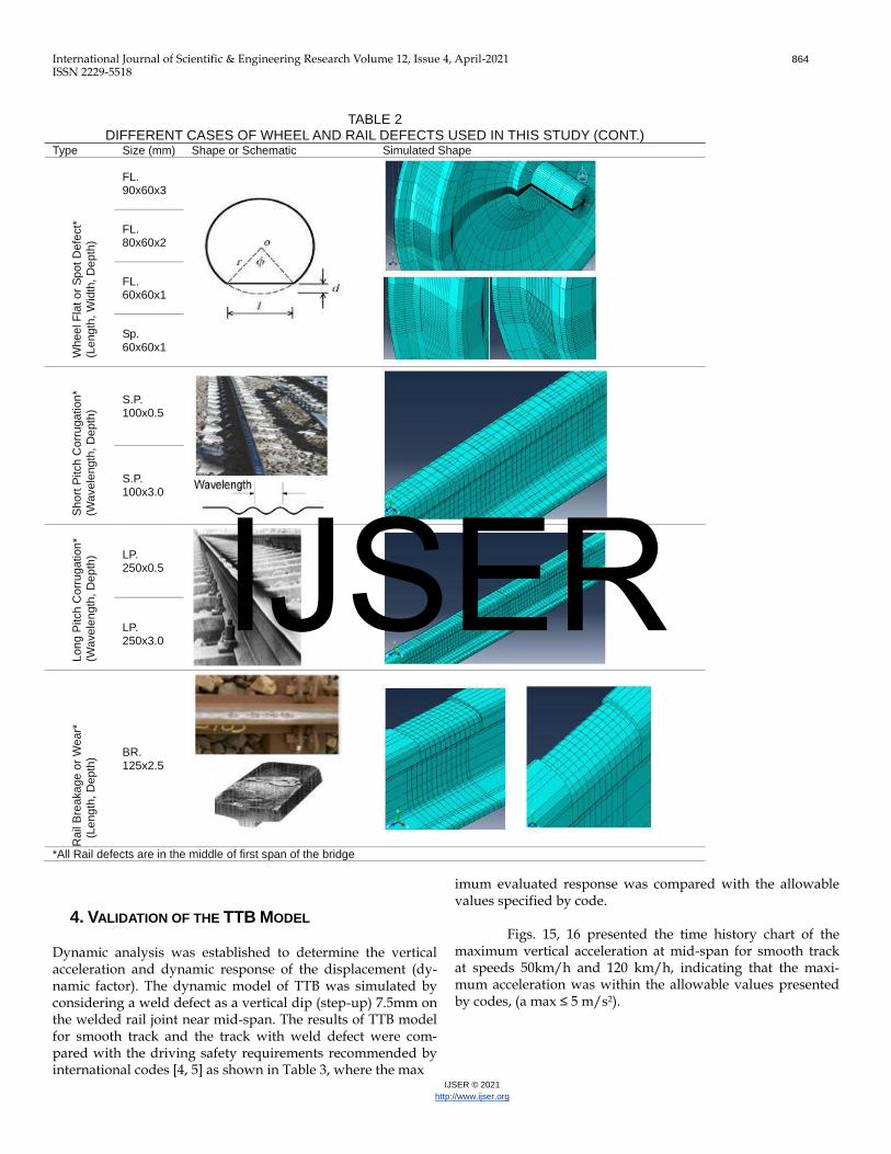
TABLE 2 DIFFERENT CASES OF WHEEL AND RAIL DEFECTS USED IN THIS STUDY (CONT.)
Type Size (mm) Shape or Schematic Simulated Shape
Wheel F
lat or
Spot D
efe
ct*
(Length
, W
idth
, D
epth
)
FL. 90x60x3
FL. 80x60x2
FL. 60x60x1
Sp. 60x60x1
Short
Pitch C
orr
ugation*
(Wavele
ngth
, D
epth
)
S.P. 100x0.5
S.P. 100x3.0
Long P
itch C
orr
ugation*
(Wavele
ngth
, D
epth
) LP. 250x0.5
LP. 250x3.0
Rail
Bre
akage o
r W
ear*
(Length
, D
epth
) BR. 125x2.5
*All Rail defects are in the middle of first span of the bridge
IJSER
International Journal of Scientific & Engineering Research Volume 12, Issue 4, April-2021 865
ISSN 2229-5518
IJSER © 2021
http://www.ijser.org
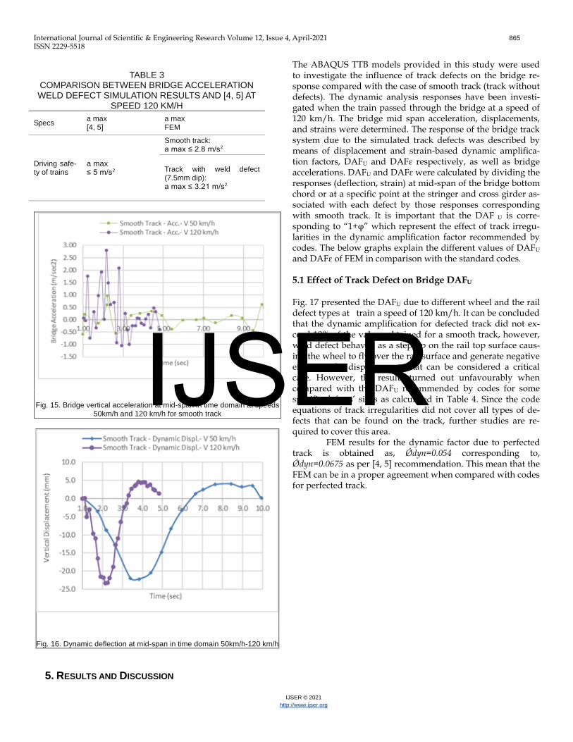
TABLE 3
COMPARISON BETWEEN BRIDGE ACCELERATION WELD DEFECT SIMULATION RESULTS AND [4, 5] AT
SPEED 120 KM/H
Specs a max [4, 5]
a max FEM
Driving safe-ty of trains
a max ≤ 5 m/s2
Smooth track: a max ≤ 2.8 m/s2
Track with weld defect (7.5mm dip): a max ≤ 3.21 m/s2
Fig. 15. Bridge vertical acceleration at mid-span in time domain at speeds 50km/h and 120 km/h for smooth track
Fig. 16. Dynamic deflection at mid-span in time domain 50km/h-120 km/h
5. RESULTS AND DISCUSSION
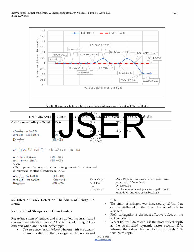
The ABAQUS TTB models provided in this study were used to investigate the influence of track defects on the bridge re-sponse compared with the case of smooth track (track without defects). The dynamic analysis responses have been investi-gated when the train passed through the bridge at a speed of 120 km/h. The bridge mid span acceleration, displacements, and strains were determined. The response of the bridge track system due to the simulated track defects was described by means of displacement and strain-based dynamic amplifica-tion factors, DAFU and DAFɛ respectively, as well as bridge accelerations. DAFU and DAFɛ were calculated by dividing the responses (deflection, strain) at mid-span of the bridge bottom chord or at a specific point at the stringer and cross girder as-sociated with each defect by those responses corresponding with smooth track. It is important that the DAF U is corre-sponding to “1+φ” which represent the effect of track irregu-larities in the dynamic amplification factor recommended by codes. The below graphs explain the different values of DAFU and DAFɛ of FEM in comparison with the standard codes. 5.1 Effect of Track Defect on Bridge DAFU
Fig. 17 presented the DAFU due to different wheel and the rail defect types at train a speed of 120 km/h. It can be concluded that the dynamic amplification for defected track did not ex-ceed 10% of the values obtained for a smooth track, however, weld defect behaved as a step up on the rail top surface caus-ing the wheel to fly over the rail surface and generate negative effect on the displacement, that can be considered a critical case. However, the results turned out unfavourably when compared with the DAFU recommended by codes for some specific defects’ sizes as calculated in Table 4. Since the code equations of track irregularities did not cover all types of de-fects that can be found on the track, further studies are re-quired to cover this area.
FEM results for the dynamic factor due to perfected track is obtained as, Ǿdyn=0.054 corresponding to, Ǿdyn=0.0675 as per [4, 5] recommendation. This mean that the FEM can be in a proper agreement when compared with codes for perfected track.
IJSER
International Journal of Scientific & Engineering Research Volume 12, Issue 4, April-2021 866
ISSN 2229-5518
IJSER © 2021
http://www.ijser.org
Fig. 17. Comparison between the dynamic factors (displacement based) of FEM and Codes
TABLE 42
DYNAMIC AMPLIFICATION FACTOR CALCULATION ACCORDING TO CODES ([1+Ǿ+Ǿ´])
Calculation according to EN 1991-2(2003) [4, 5] FEM
where,
φ'dyn represent the effect of track in perfect geometrical condition, and
φ'' represent the effect of track irregularities.
V=120 km/h
K= 0.0756
no = 3.455
Ǿ = 0.0675
Ǿdyn=0.054
V=33.33m/s
no=3.455
α =1
Øˊˊ=0.00006
Ǿdyn=0.009 for the case of short pitch corru-
gation with 0.5mm depth
Øˊˊdyn=0.054,
for the case of short pitch corrugation with
3mm depth and case of rail breakage
5.2 Effect of Track Defect on The Strain of Bridge Ele-ments
5.2.1 Strain of Stringers and Cross Girders
Regarding strain of stringer and cross girder, the strain-based dynamic amplification factor DAFɛ is plotted in Fig. 18 for different wheel and the rail defect types.
• The response for all defects inherent with the dynam-ic amplification of the cross girder did not exceed
10%. • The strain of stringers was increased by 20%m, that
can be attributed to the direct fixation of rails to stringers.
• Pitch corrugation is the most effective defect on the stringer strain.
• Wheel flat with 3mm depth is the most critical depth as the strain-based dynamic factor reaches 15%, whereas the values dropped to approximately 10% with 2mm depth.
IJSER
International Journal of Scientific & Engineering Research Volume 12, Issue 4, April-2021 867
ISSN 2229-5518
IJSER © 2021
http://www.ijser.org
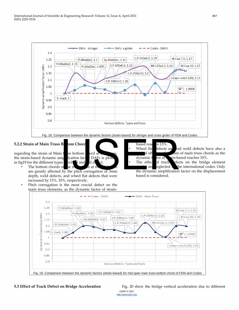
Fig. 18. Comparison between the dynamic factors (strain-based) for stringer and cross girder of FEM and Codes
5.2.2 Strain of Main Truss Bottom Chord
regarding the strain of Main truss bottom chord at mid span, the strain-based dynamic amplification factor DAFɛ is plotted in fig19 for the different types of wheel and rail defect.
• The bottom chords of the main truss at the mid-span are greatly affected by the pitch corrugation of 3mm depth, weld defects, and wheel flat defects that were increased by 13%, 10%, respectively.
• Pitch corrugation is the most crucial defect on the main truss elements, as the dynamic factor of strain-
based reaches 13%. • Wheel flat defects and rail weld defects have also a
critical effect on the strain of main truss chords as the dynamic factor of strain-based reaches 10%.
• The effect of track defects on the bridge element strains are neglected by the international codes. Only the dynamic amplification factor on the displacement based is considered.
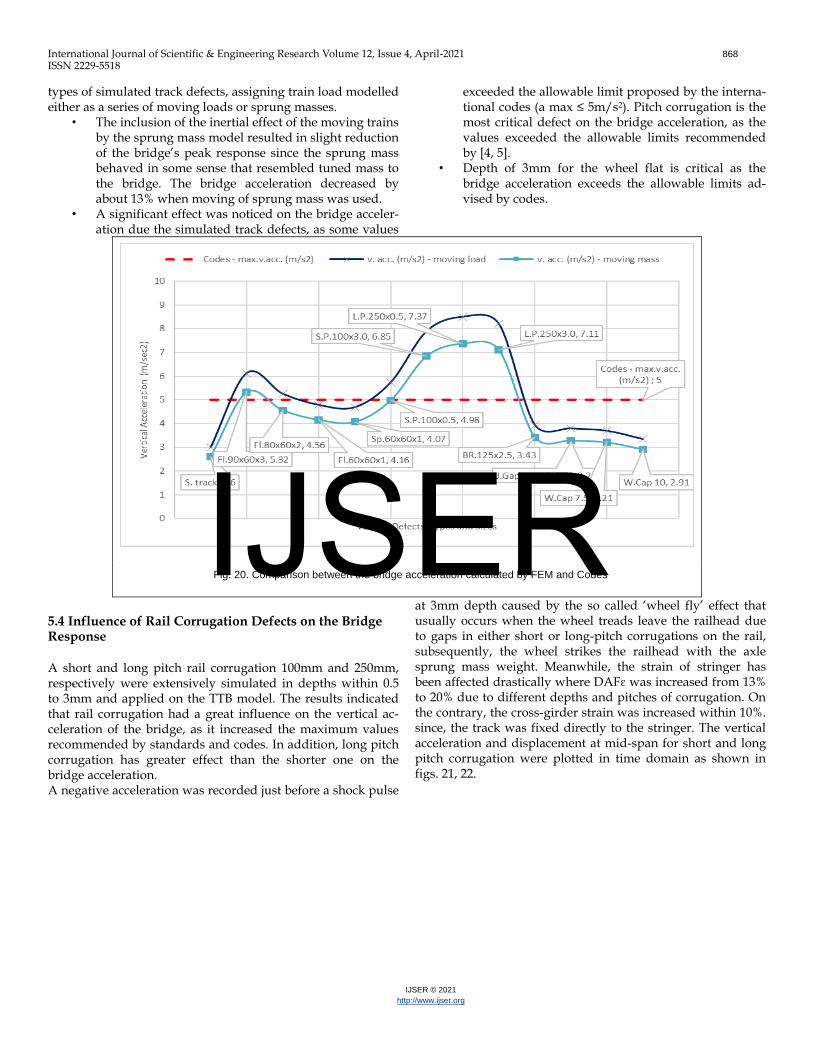
Fig. 19. Comparison between the dynamic factors (strain-based) for mid span main truss bottom chord of FEM and Codes 5.3 Effect of Track Defect on Bridge Acceleration Fig. 20 show the bridge vertical acceleration due to different
IJSER
International Journal of Scientific & Engineering Research Volume 12, Issue 4, April-2021 868
ISSN 2229-5518
IJSER © 2021
http://www.ijser.org
types of simulated track defects, assigning train load modelled either as a series of moving loads or sprung masses.
• The inclusion of the inertial effect of the moving trains by the sprung mass model resulted in slight reduction of the bridge’s peak response since the sprung mass behaved in some sense that resembled tuned mass to the bridge. The bridge acceleration decreased by about 13% when moving of sprung mass was used.
• A significant effect was noticed on the bridge acceler-ation due the simulated track defects, as some values
exceeded the allowable limit proposed by the interna-tional codes (a max ≤ 5m/s2). Pitch corrugation is the most critical defect on the bridge acceleration, as the values exceeded the allowable limits recommended by [4, 5].
• Depth of 3mm for the wheel flat is critical as the bridge acceleration exceeds the allowable limits ad-vised by codes.
Fig. 20. Comparison between the bridge acceleration calculated by FEM and Codes
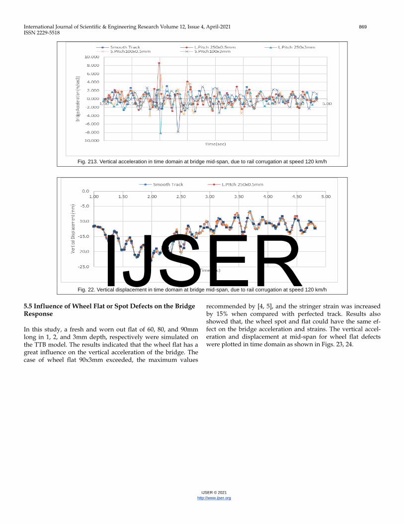
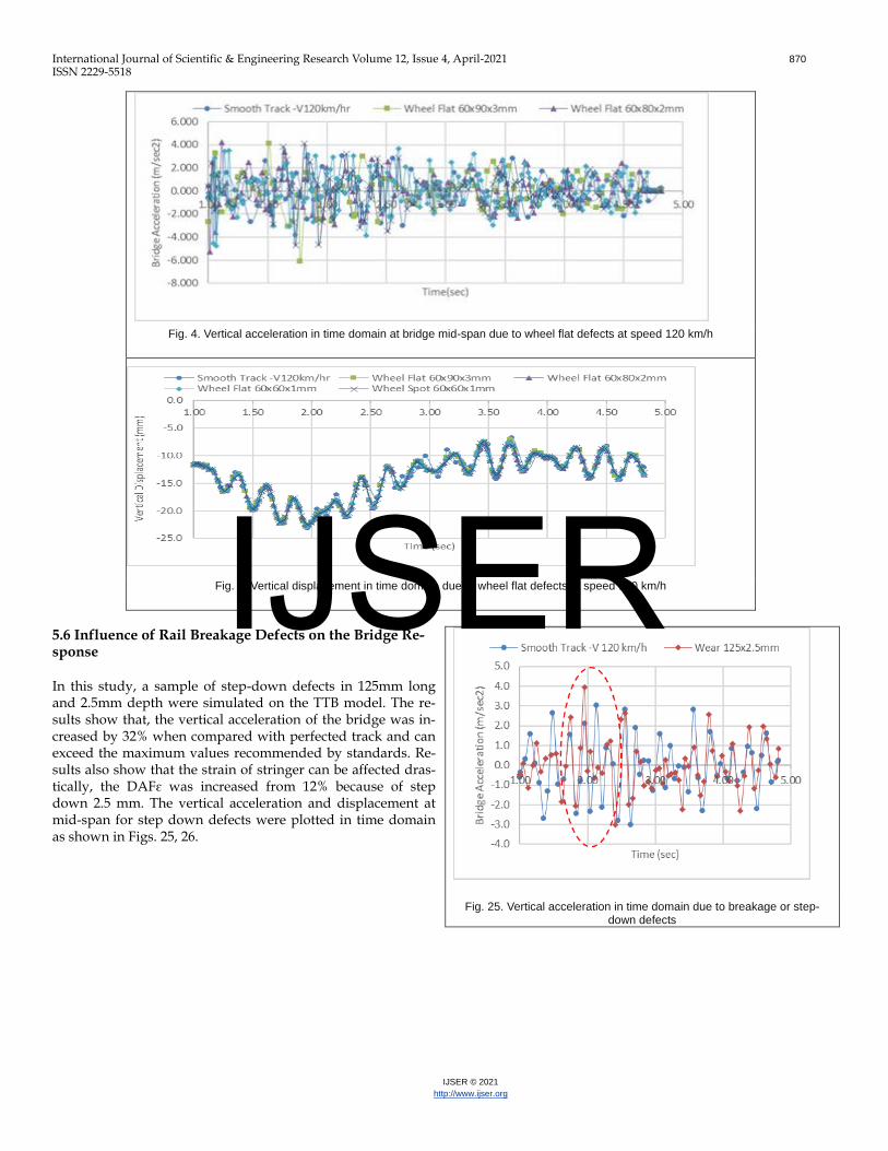
5.4 Influence of Rail Corrugation Defects on the Bridge Response
A short and long pitch rail corrugation 100mm and 250mm, respectively were extensively simulated in depths within 0.5 to 3mm and applied on the TTB model. The results indicated that rail corrugation had a great influence on the vertical ac-celeration of the bridge, as it increased the maximum values recommended by standards and codes. In addition, long pitch corrugation has greater effect than the shorter one on the bridge acceleration. A negative acceleration was recorded just before a shock pulse
at 3mm depth caused by the so called ‘wheel fly’ effect that usually occurs when the wheel treads leave the railhead due to gaps in either short or long-pitch corrugations on the rail, subsequently, the wheel strikes the railhead with the axle sprung mass weight. Meanwhile, the strain of stringer has been affected drastically where DAFɛ was increased from 13% to 20% due to different depths and pitches of corrugation. On the contrary, the cross-girder strain was increased within 10%. since, the track was fixed directly to the stringer. The vertical acceleration and displacement at mid-span for short and long pitch corrugation were plotted in time domain as shown in figs. 21, 22.
IJSER
International Journal of Scientific & Engineering Research Volume 12, Issue 4, April-2021 869
ISSN 2229-5518
IJSER © 2021
http://www.ijser.org
Fig. 213. Vertical acceleration in time domain at bridge mid-span, due to rail corrugation at speed 120 km/h
Fig. 22. Vertical displacement in time domain at bridge mid-span, due to rail corrugation at speed 120 km/h
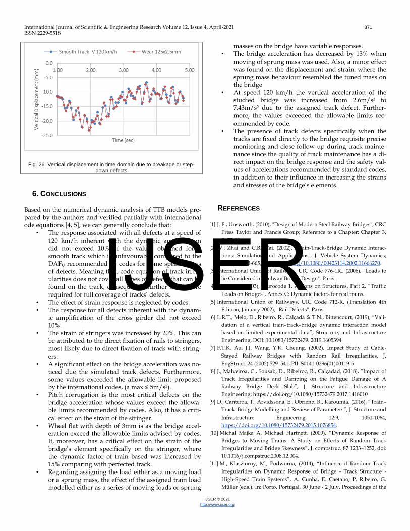
5.5 Influence of Wheel Flat or Spot Defects on the Bridge Response
In this study, a fresh and worn out flat of 60, 80, and 90mm long in 1, 2, and 3mm depth, respectively were simulated on the TTB model. The results indicated that the wheel flat has a great influence on the vertical acceleration of the bridge. The case of wheel flat 90x3mm exceeded, the maximum values
recommended by [4, 5], and the stringer strain was increased by 15% when compared with perfected track. Results also showed that, the wheel spot and flat could have the same ef-fect on the bridge acceleration and strains. The vertical accel-eration and displacement at mid-span for wheel flat defects were plotted in time domain as shown in Figs. 23, 24.
IJSER
International Journal of Scientific & Engineering Research Volume 12, Issue 4, April-2021 870
ISSN 2229-5518
IJSER © 2021
http://www.ijser.org
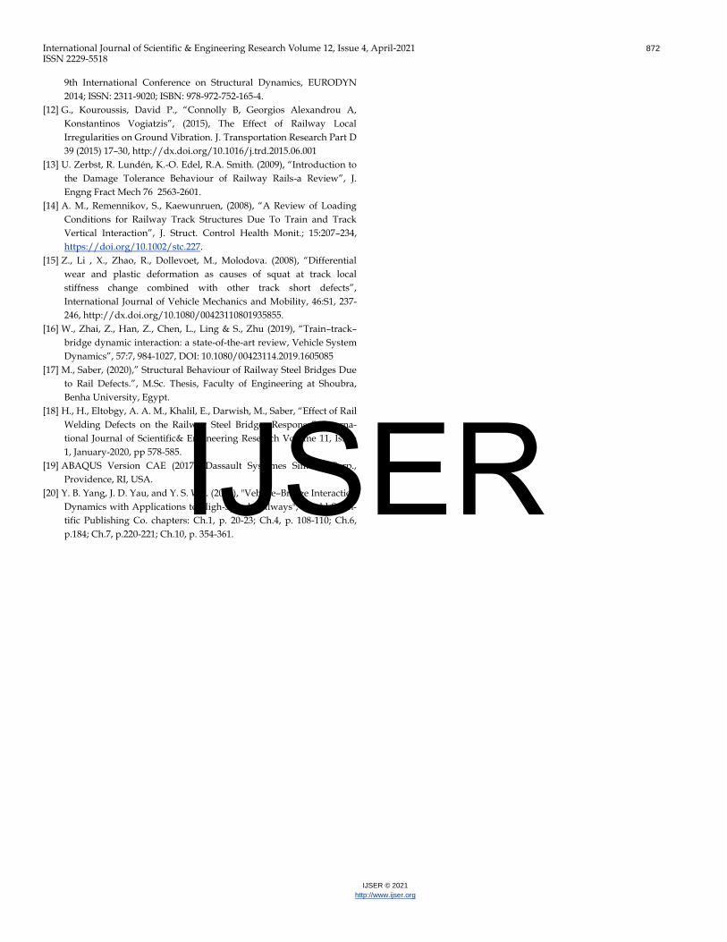
5.6 Influence of Rail Breakage Defects on the Bridge Re-sponse
In this study, a sample of step-down defects in 125mm long and 2.5mm depth were simulated on the TTB model. The re-sults show that, the vertical acceleration of the bridge was in-creased by 32% when compared with perfected track and can exceed the maximum values recommended by standards. Re-sults also show that the strain of stringer can be affected dras-tically, the DAFɛ was increased from 12% because of step down 2.5 mm. The vertical acceleration and displacement at mid-span for step down defects were plotted in time domain as shown in Figs. 25, 26.
Fig. 25. Vertical acceleration in time domain due to breakage or step-down defects
Fig. 4. Vertical acceleration in time domain at bridge mid-span due to wheel flat defects at speed 120 km/h
Fig. 5. Vertical displacement in time domain due to wheel flat defects at speed 120 km/h IJSER
International Journal of Scientific & Engineering Research Volume 12, Issue 4, April-2021 871
ISSN 2229-5518
IJSER © 2021
http://www.ijser.org
Fig. 26. Vertical displacement in time domain due to breakage or step-down defects
6. CONCLUSIONS
Based on the numerical dynamic analysis of TTB models pre-pared by the authors and verified partially with international ode equations [4, 5], we can generally conclude that:
• The response associated with all defects at a speed of 120 km/h inherent with the dynamic amplification did not exceed 10% of the values obtained for a smooth track which is unfavourably compared to the DAFU recommended by codes for some specific sizes of defects. Meaning that, code equation of track irreg-ularities does not cover all types of defects that can be found on the track, consequently further studies are required for full coverage of tracks’ defects.
• The effect of strain response is neglected by codes. • The response for all defects inherent with the dynam-
ic amplification of the cross girder did not exceed 10%.
• The strain of stringers was increased by 20%. This can be attributed to the direct fixation of rails to stringers, most likely due to direct fixation of track with string-ers.
• A significant effect on the bridge acceleration was no-ticed due the simulated track defects. Furthermore, some values exceeded the allowable limit proposed by the international codes, (a max ≤ 5m/s2).
• Pitch corrugation is the most critical defects on the bridge acceleration whose values exceed the allowa-ble limits recommended by codes. Also, it has a criti-cal effect on the strain of the stringer.
• Wheel flat with depth of 3mm is as the bridge accel-eration exceed the allowable limits advised by codes. It, moreover, has a critical effect on the strain of the bridge’s element specifically on the stringer, where the dynamic factor of train based was increased by 15% comparing with perfected track.
• Regarding assigning the load either as a moving load or a sprung mass, the effect of the assigned train load modelled either as a series of moving loads or sprung
masses on the bridge have variable responses. • The bridge acceleration has decreased by 13% when
moving of sprung mass was used. Also, a minor effect was found on the displacement and strain. where the sprung mass behaviour resembled the tuned mass on the bridge
• At speed 120 km/h the vertical acceleration of the studied bridge was increased from 2.6m/s2 to 7.43m/s2 due to the assigned track defect. Further-more, the values exceeded the allowable limits rec-ommended by code.
• The presence of track defects specifically when the tracks are fixed directly to the bridge requisite precise monitoring and close follow-up during track mainte-nance since the quality of track maintenance has a di-rect impact on the bridge response and the safety val-ues of accelerations recommended by standard codes, in addition to their influence in increasing the strains and stresses of the bridge’s elements.
REFERENCES
[1] J. F., Unsworth, (2010), "Design of Modern Steel Railway Bridges", CRC
Press Taylor and Francis Group; Reference to a Chapter: Chapter 3,
P. 77-80.
[2] W., Zhai and C.B., Cai. (2002), "Train-Track-Bridge Dynamic Interac-
tions: Simulation and Applications", J. Vehicle System Dynamics;
37:sup1, 653-665, https://doi.org/10.1080/00423114.2002.11666270.
[3] International Union of Railways. UIC Code 776-1R., (2006), "Loads to
be Considered in Railway Bridge Design". Paris.
[4] EN 1991-2 (2003), "Eurocode 1, Actions on Structures, Part 2, “Traffic
Loads on Bridges", Annex C: Dynamic factors for real trains.
[5] International Union of Railways. UIC Code 712-R. (Translation 4th
Edition, January 2002), "Rail Defects". Paris.
[6] L.R.T., Melo, D., Ribeiro, R., Calçada & T.N., Bittencourt, (2019), “Vali-
dation of a vertical train–track–bridge dynamic interaction model
based on limited experimental data”, Structure, and Infrastructure
Engineering, DOI: 10.1080/15732479. 2019.1605394
[7] F.T.K. Au, J.J. Wang, Y.K. Cheung. (2002), Impact Study of Cable-
Stayed Railway Bridges with Random Rail Irregularities. J.
EngStruct. 24 (2002) 529–541, PII: S0141-0296(01)00119-5
[8] J., Malveiroa, C., Sousab, D., Ribeiroc, R., Calçadad, (2018), “Impact of
Track Irregularities and Damping on the Fatigue Damage of A
Railway Bridge Deck Slab”, J. Structure and Infrastructure
Engineering; https://doi.org/10.1080/15732479.2017.1418010
[9] D., Canteroa, T., Arvidssona, E., Obrienb, R., Karoumia, (2016), “Train–
Track–Bridge Modelling and Review of Parameters”, J. Structure and
Infrastructure Engineering, 12:9, 1051-1064,
https://doi.org/10.1080/15732479.2015.1076854.
[10] Michal Majka A, Michael Hartnett. (2009), “Dynamic Response of
Bridges to Moving Trains: A Study on Effects of Random Track
Irregularities and Bridge Skewness”, J. compstruc. 87 1233–1252, doi:
10.1016/j.compstruc.2008.12.004.
[11] M., Klasztorny, M., Podworna, (2014), “Influence if Random Track
Irregularities on Dynamic Response of Bridge - Track Structure -
High-Speed Train Systems”, A. Cunha, E. Caetano, P. Ribeiro, G.
Müller (eds.). In: Porto, Portugal, 30 June - 2 July, Proceedings of the
IJSER
International Journal of Scientific & Engineering Research Volume 12, Issue 4, April-2021 872
ISSN 2229-5518
IJSER © 2021
http://www.ijser.org
9th International Conference on Structural Dynamics, EURODYN
2014; ISSN: 2311-9020; ISBN: 978-972-752-165-4.
[12] G., Kouroussis, David P., “Connolly B, Georgios Alexandrou A,
Konstantinos Vogiatzis”, (2015), The Effect of Railway Local
Irregularities on Ground Vibration. J. Transportation Research Part D
39 (2015) 17–30, http://dx.doi.org/10.1016/j.trd.2015.06.001
[13] U. Zerbst, R. Lundén, K.-O. Edel, R.A. Smith. (2009), “Introduction to
the Damage Tolerance Behaviour of Railway Rails-a Review”, J.
Engng Fract Mech 76 2563-2601.
[14] A. M., Remennikov, S., Kaewunruen, (2008), “A Review of Loading
Conditions for Railway Track Structures Due To Train and Track
Vertical Interaction”, J. Struct. Control Health Monit.; 15:207–234,
https://doi.org/10.1002/stc.227.
[15] Z., Li , X., Zhao, R., Dollevoet, M., Molodova. (2008), “Differential
wear and plastic deformation as causes of squat at track local
stiffness change combined with other track short defects”,
International Journal of Vehicle Mechanics and Mobility, 46:S1, 237-
246, http://dx.doi.org/10.1080/00423110801935855.
[16] W., Zhai, Z., Han, Z., Chen, L., Ling & S., Zhu (2019), “Train–track–
bridge dynamic interaction: a state-of-the-art review, Vehicle System
Dynamics”, 57:7, 984-1027, DOI: 10.1080/00423114.2019.1605085
[17] M., Saber, (2020),” Structural Behaviour of Railway Steel Bridges Due
to Rail Defects.”, M.Sc. Thesis, Faculty of Engineering at Shoubra,
Benha University, Egypt.
[18] H., H., Eltobgy, A. A. M., Khalil, E., Darwish, M., Saber, “Effect of Rail
Welding Defects on the Railway Steel Bridges Response”, Interna-
tional Journal of Scientific& Engineering Research Volume 11, Issue
1, January-2020, pp 578-585.
[19] ABAQUS Version CAE (2017), Dassault Systèmes Simulia Corp.,
Providence, RI, USA.
[20] Y. B. Yang, J. D. Yau, and Y. S. Wu. (2004), "Vehicle–Bridge Interaction
Dynamics with Applications to High-Speed Railways", World Scien-
tific Publishing Co. chapters: Ch.1, p. 20-23; Ch.4, p. 108-110; Ch.6,
p.184; Ch.7, p.220-221; Ch.10, p. 354-361.
IJSER