Embed Size (px)
Citation preview
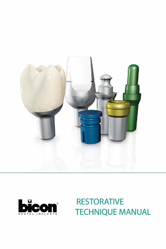
RESTORATIVE TECHNIQUE MANUAL

1
CERAmo-mETAL REsToRATIons 2–11
DIRECT ABuTmEnT LEvEL ImpREssIon 3
CEmEnTATIon oF CRown 4
InDIRECT ABuTmEnT LEvEL ImpREssIon 5–6
non-shouLDERED ABuTmEnT sELECTIon GuIDE 7–8
ImpREssIon opTIons 9
TEmpoRIzATIon opTIons 10
ABuTmEnT sELECTIon GuIDE 11
BREvIs™ ovERDEnTuRE sysTEm . . . . . . . . . . . . . . . . . . . . . . . . 12–22
BREvIs™ ABuTmEnT sysTEm 13–14
BREvIs™ ChAIRsIDE TEChnIquE 15–20
InDIRECT TRAnsFER TEChnIquE 21
REmovInG/InsERTInG RuBBER o-RInG 22
LoCAToR® ABuTmEnT sysTEm . . . . . . . . . . . . . . . . . . . . . . . . . 23–28
LoCAToR® ABuTmEnT sysTEm 24–25
LoCAToR® ChAIRsIDE TEChnIquE 26–27
LoCAToR® housInG CAp AssEmBLy 28
AppEnDIX . . . . . . . . . . . . . . . . . . . . . . . . . . . . . . . . . . . . . . . . . . . 29–37
IAC® poLIshInG TEChnIquE 30
mAXILLARy AnTERIoR sEATInG GuIDE 31–32
ADDInG InTER-pRoXImAL ConTACTs To An IAC® 33–34
suRGICAL TEmpLATE FABRICATIon 35–37
ABuTmEnT REmovAL TEChnIquE 38
TABLE Of CONTENTS

2
CERAmo-mETAL REsToRATIons
3
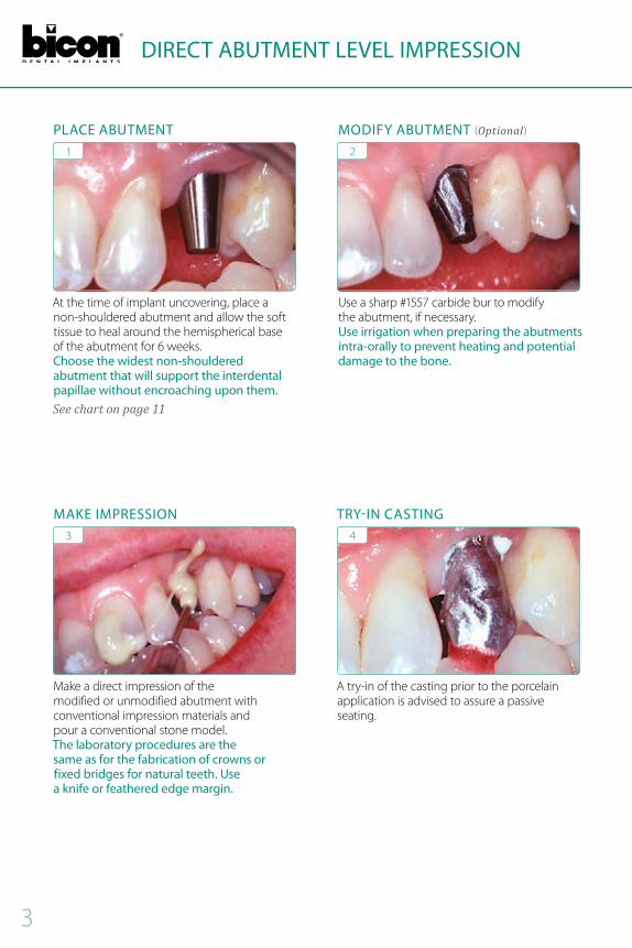
DIRECT ABUTMENT LEVEL IMPRESSION
At the time of implant uncovering, place a non-shouldered abutment and allow the soft tissue to heal around the hemispherical base of the abutment for 6 weeks Choose the widest non-shouldered abutment that will support the interdental papillae without encroaching upon them.See chart on page 11
1
PLACE ABUTMENT
make a direct impression of the modified or unmodified abutment with conventional impression materials and pour a conventional stone model The laboratory procedures are the same as for the fabrication of crowns or fixed bridges for natural teeth. Use a knife or feathered edge margin.
3
MAkE IMPRESSION
use a sharp #1557 carbide bur to modify the abutment, if necessary Use irrigation when preparing the abutments intra-orally to prevent heating and potential damage to the bone.
2
MODIfy ABUTMENT (Optional)
A try-in of the casting prior to the porcelain application is advised to assure a passive seating
4
TRy-IN CASTINg

4
KEys To suCCEss■■ Choose the widest abutment to accommodate the edentulous space without encroaching upon the interdental papillae
■■ 3 5mm abutments are recommended only for mandibular incisors; 4 0mm abutments are primarily used for maxillary laterals and bicuspids; 5 0mm abutments are more universal in their use; 6 5mm and 7 5mm abutments are ideally suited for molars
■■ The abutment can rotate 360˚ to reach a desired position or to achieve parallelism prior to seating
■■ use an abutment preparation holder (260-101-395) when modifying abutments extra-orally
■■ use irrigation when preparing an abutment intra-orally
■■ Do not make an impression with the emergence cuff
■■ The use of retraction cord is not necessary ■■ An emergence cuff can act as a means of gingival retraction
■■ The casting may end with a knife or feathered edge margin anywhere along the coronal aspect of the abutment
■■ use minimal amount of cement at the cervical margin to avoid hydraulic forces which may prevent the crown from seating fully
CEMENTATION Of CROwN
After any needed occlusal, interproximal, or aesthetic contouring, cement the crown conventionally with minimal cement only at the cervical aspect of the crown to avoid adverse hydraulic forces Care must be taken to remove all extraneous cement
5
CROwN
Recheck the occlusion after cementation
6
RECHECk OCCLUSION

5
INDIRECT ABUTMENT LEVEL IMPRESSION wITH PLASTIC SLEEVE*
Definitively seat the abutment with a gentle tapping force snap impression sleeves onto the unmodified abutment See chart on page 11
1
SNAP ON SLEEVES
orientate the external flat(s) of the colored abutment transfer die with the internal flat(s) of the correspondingly colored non-shouldered impression sleeve prior to snapping it into the impression It is imperative that the correct abutment transfer die be used. The diameter and height of the transfer die should match the diameter and height of the abutment
3
INSERT ABUTMENT TRANSfER DIE
snap the appropriate impression sleeve or temporization sleeve onto the colored abutment transfer die and modify as necessary
5
SNAP ON SLEEVES
Inject impression material around the impression sleeves and make impression
2
INJECT IMPRESSION MATERIAL
pour a soft tissue or stone model
4
fABRICATE MODEL
Incorporate the sleeve into the wax pattern for the metal casting
6
wAxINg

6
INDIRECT ABUTMENT LEVEL IMPRESSION wITH PLASTIC SLEEVE*
*SEE PAgES 7 AND 8 fOR PROSTHETIC COMPONENTS
Try-in metal casting for a passive fit
7
TRy-IN CASTINg
Final view of cemented Ceramo-metal restoration
9
fINAL CROwNS
Apply porcelain following normal layering techniques until the crown is completed
PORCELAIN APPLICATION8
KEys To suCCEss■■ The diameter and height of the transfer dies are sized to match the diameter and height of the abutments
■■ It is paramount that the proper abutment transfer die height be chosen to pour the stone model since all transfer dies of the same color will snap into the impression sleeve of that color
■■ The temporization sleeves are more retentive than the impression sleeves

7
NON-SHOULDERED ABUTMENT SELECTION gUIDE
4.0mm Diameter 5.0mm Diameter 6.5mm Diameter 7.5mm Diameter
0˚ 15˚ 25˚ 0˚ 15˚ 0˚ 15˚ 0˚ 15˚ 25˚ 0˚ 15˚ 0˚ 15˚ 0˚ 15˚ 0˚ 15˚ 0˚ 15˚
4 .0 x 6 .5 0˚260-340-001
4 .0 x 6 .5 15˚260-340-015
4 .0 x 10 0˚260-340-101
4 .0 x 10 15˚260-340-115
5 .0 x 5 .0 0˚260-350-050
5 .0 x 5 .0 15˚260-350-055
5 .0 x 6 .5 0˚260-350-001
5 .0 x 6 .5 15˚260-350-015
5 .0 x 6 .5 25˚260-350-025
5 .0 x 10 0˚260-350-101
5 .0 x 10 15˚260-350-115
5 .0 x 12 0˚260-350-201
5 .0 x 12 15˚260-350-215
6 .5 x 5 .0 0˚260-365-050
6 .5 x 5 .0 15˚260-365-055
6 .5 x 6 .5 0˚260-365-001
6 .5 x 6 .5 15˚260-365-015
7 .5 x 8 .0 0˚260-375-801
7 .5 x 8 .0 15˚260-375-815
4 .0 x 6 .5 0˚260-240-001
4 .0 x 6 .5 15˚260-240-015
4 .0 x 6 .5 25˚260-240-025
4 .0 x 10 0˚260-240-101
4 .0 x 10 15˚260-240-115
5 .0 x 6 .5 0˚260-250-001
5 .0 x 6 .5 15˚260-250-015
5 .0 x 6 .5 25˚260-250-025
5 .0 x 10 0˚260-250-111
5 .0 x 10 15˚260-250-115
6 .5 x 5 .0 0˚260-265-050
6 .5 x 5 .0 15˚260-265-055
4 .0 x 6 .5 0˚260-140-002
4 .0 x 6 .5 15˚260-140-015
4 .0 x 6 .5 25˚260-140-025
4 .0 x 10 0˚260-140-101
4 .0 x 10 15˚260-140-115
5 .0 x 5 .0 0˚260-150-050
5 .0 x 5 .0 15˚260-150-055
5 .0 x 6 .5 0˚260-150-001
5 .0 x 6 .5 15˚260-150-015
5 .0 x 6 .5 25˚260-150-025
5 .0 x 12 0˚260-150-201
5 .0 x 12 15˚260-150-215
ReStoRAtive/LABoRAtoRy Kit
4 .0 x 6 .5mm260-140-465
4 .0 x 10mm260-140-410
5 .0 x 5 .0mm260-150-450
5 .0 x 6 .5mm260-150-465
5 .0 x 10mm260-150-410
5 .0 x 12mm260-150-412
6 .5 x 5 .0mm 260-165-450
6 .5 x 6 .5mm260-165-465
7 .5 x 8 .0mm260-175-480
4 .0mm260-140-165
5 .0mm260-150-165
5 .0mm260-150-165
6 .5mm260-165-165
7 .5mm260-175-165
10.0
6.5
5.0
Top of Implant
10.0
mm
2.5mm
2.5mm
12.0
Top of Implant
10.0
8.0
6.5
5.0
12.0
mm
12.0
10.0
8.0
6.5
5.0
12.0
mm
12.0
10.0
6.5
5.0
Top of Implant
12.0
mm
3.0mm
™
IMPLANTS 3.0mm Post
2.5mm Post
2.0mm Post
™
IMPLANTSNARROW
™™
■■ snap-on sleeves are only specific for abutment diameter ■■ Abutment height is not a criterion for proper selection of snap-on sleeves
noTEs

8
4.0mm Diameter 5.0mm Diameter 6.5mm Diameter 7.5mm Diameter
0˚ 15˚ 25˚ 0˚ 15˚ 0˚ 15˚ 0˚ 15˚ 25˚ 0˚ 15˚ 0˚ 15˚ 0˚ 15˚ 0˚ 15˚ 0˚ 15˚
4 .0 x 6 .5 0˚260-340-001
4 .0 x 6 .5 15˚260-340-015
4 .0 x 10 0˚260-340-101
4 .0 x 10 15˚260-340-115
5 .0 x 5 .0 0˚260-350-050
5 .0 x 5 .0 15˚260-350-055
5 .0 x 6 .5 0˚260-350-001
5 .0 x 6 .5 15˚260-350-015
5 .0 x 6 .5 25˚260-350-025
5 .0 x 10 0˚260-350-101
5 .0 x 10 15˚260-350-115
5 .0 x 12 0˚260-350-201
5 .0 x 12 15˚260-350-215
6 .5 x 5 .0 0˚260-365-050
6 .5 x 5 .0 15˚260-365-055
6 .5 x 6 .5 0˚260-365-001
6 .5 x 6 .5 15˚260-365-015
7 .5 x 8 .0 0˚260-375-801
7 .5 x 8 .0 15˚260-375-815
4 .0 x 6 .5 0˚260-240-001
4 .0 x 6 .5 15˚260-240-015
4 .0 x 6 .5 25˚260-240-025
4 .0 x 10 0˚260-240-101
4 .0 x 10 15˚260-240-115
5 .0 x 6 .5 0˚260-250-001
5 .0 x 6 .5 15˚260-250-015
5 .0 x 6 .5 25˚260-250-025
5 .0 x 10 0˚260-250-111
5 .0 x 10 15˚260-250-115
6 .5 x 5 .0 0˚260-265-050
6 .5 x 5 .0 15˚260-265-055
4 .0 x 6 .5 0˚260-140-002
4 .0 x 6 .5 15˚260-140-015
4 .0 x 6 .5 25˚260-140-025
4 .0 x 10 0˚260-140-101
4 .0 x 10 15˚260-140-115
5 .0 x 5 .0 0˚260-150-050
5 .0 x 5 .0 15˚260-150-055
5 .0 x 6 .5 0˚260-150-001
5 .0 x 6 .5 15˚260-150-015
5 .0 x 6 .5 25˚260-150-025
5 .0 x 12 0˚260-150-201
5 .0 x 12 15˚260-150-215
ReStoRAtive/LABoRAtoRy Kit
4 .0 x 6 .5mm260-140-465
4 .0 x 10mm260-140-410
5 .0 x 5 .0mm260-150-450
5 .0 x 6 .5mm260-150-465
5 .0 x 10mm260-150-410
5 .0 x 12mm260-150-412
6 .5 x 5 .0mm 260-165-450
6 .5 x 6 .5mm260-165-465
7 .5 x 8 .0mm260-175-480
4 .0mm260-140-165
5 .0mm260-150-165
5 .0mm260-150-165
6 .5mm260-165-165
7 .5mm260-175-165
Top of Implant
10.0
mm
2.5mm
10.0
6.5
5.0
2.5mm Top of Implant
12.0
mm
12.0
10.0
8.0
6.5
5.0
12.0
mm
12.0
10.0
8.0
6.5
5.0
12.0
10.0
6.5
5.0
Top of Implant
12.0
mm
3.0mm
■■ Transfer dies correspond to exact diameter and height of abutment placed ■■ Because of machining tolerances, sleeves may not reach the height of contour for some angled abutments

9
IMPRESSION OPTIONS
opTIon T wo: DIRECT ABuTmEnT LEvEL ImpREssIon1 2 3 4
Choose an appropriately sized abutment and definitively seat the abutment with a gentle tapping force .
The abutment may be modified intra-orally with irrigation or extra-orally with a #1557 carbide bur, if necessary .
Inject impression material around abutment for a direct impression . Pour a stone model .
Fabricate crown conventionally at laboratory . Insert crown with minimal cement .
opTIon ThREE: InDIRECT ABuTmEnT LEvEL ImpREssIon1 2 3 4
Definitively seat the abutment with a gentle tapping force . Snap impression sleeves onto the unmodified abutment .
Inject impression material around the impression sleeves and make impression .
Withdraw the plastic impression sleeves in the impression . Choose appropriately sized aluminum transfer die and insert the die into the plastic sleeve .
Pour a soft tissue model . Fabricate crowns conventionally . See Bicon Technique Manuals for further information on this procedure .
opTIon onE: ImpLAnT-LEvEL ImpREssIon1
4
2
5
3
6
Choose the appropriately sized titanium impression post according to the diameter of the implant well .
Inject impression material around the plastic impression sleeve and make impression .
Insert the titanium impression post into the well of the implant with finger pressure only .
After making the impression, plastic impression sleeve should be withdrawn within the impression while titanium post remains in the implant well .
Snap the appropriate impression sleeve onto the impression post .
Remove titanium impression post from implant . Assemble the post with the appropriate implant analog . Insert this unit into the plastic sleeve in the impression . Pour soft tissue model . The laboratory technician may now choose the proper abutment for a PFM or IAC® restoration .
Impression Post
Titanium
Impression SleevePlastic
Implant Analog
Titanium
3.0mm Post
2.5mm Post
2.0mm Post

10
TEMPORIzATION OPTIONS
opTIon onE: TRAnsITIonAL REsToRATIon wITh sLEEvE1
5
2
6
3
7
4
8
Insert appropriate non-shouldered or stealth shouldered abutment . The diameter of the abutment is dictated by the anatomy of the interdental papillae . The abutment should support the papillae without encroaching upon them .
Insert appropriate non-shouldered or stealth shouldered abutment . The diameter of the abutment is dictated by the anatomy of the interdental papillae . The abutment should support the papillae without encroaching upon them .
Tap the abutment in the long axis of the abutment post and implant well .
Tap the abutment in the long axis of the abutment post and implant well .
Orientate the internal flat(s) of the appropriate temporization sleeve with the external flat(s) of the abutment prior to snapping it onto the abutment .
Orientate the internal flat(s) of the appropriate temporization sleeve with the external flat(s) of the abutment prior to snapping it onto the abutment .
Confirm the appropriateness of the temporization sleeve with a vacuum formed template . Adjust the sleeve as necessary .
Confirm the appropriateness of the temporization sleeve with a vacuum formed template . Adjust the sleeve as necessary .
1 2
At time of uncovering, place a temporary abutment . The abutment will support the soft tissue and assist in the formation of the gingival sulcus . The abutment may be modified to achieve the desired contour . Transitional crowns should not be placed on temporary abutments . See Bicon catalogs for a complete listing of abutment sizes and shapes that are available .
opTIon T wo: TEmpoRIzATIon wITh A TEmpoRARy ABuTmEnT43
opTIon ThREE: A TRAnsITIonAL pRosThEsIs In ThE AEsThETIC zonE2 3 4
Choose appropriately sized temporary abutment . See Option #2 above .
Insert temporary abutment into the implant well and gently seat the abutment by tapping on the head of the abutment . Removal of the abutment may be achieved with a variety of extraction forceps .
In aesthetic areas, a flipper may be inserted for aesthetics and function while tissue is healing around the temporary abutments .
View of inserted provisional restoration .
1
4.0 x 4.5 4.0 x 6.5 5.0 x 4.5 5.0 x 6.5

11
ABUTMENT SELECTION gUIDE
non-shouLDERED ABuTmEnTsThe chart below contains recommendations only Actual clinical conditions and the clinician’s assessment of the patient should be the main criteria for choosing the size of an abutment for a particular situation
■■ 5 0mm DIAmETER
4 0mm DIAmETER or wIDER
4 0mm DIAmETER or wIDER
3 5mm DIAmETER or wIDER
6 5mm DIAmETER or wIDER
6 5mm DIAmETER or wIDER
5 0mm DIAmETER or wIDER 5 0mm DIAmETER
or wIDER
mAXILLA mAnDIBLE
12
BREvIs™ ovERDEnTuRE sysTEm
13
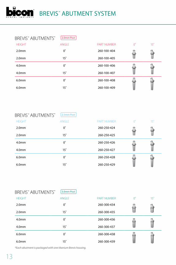
BREvIs™ ABuTmEnTs* 2.0mm Post
hEIGhT AnGLE pART numBER 0˚ 15˚
2.0mm 0˚ 260-100-404
2.0mm 15˚ 260-100-405
4.0mm 0˚ 260-100-406
4.0mm 15˚ 260-100-407
6.0mm 0˚ 260-100-408
6.0mm 15˚ 260-100-409
BREvIs™ ABuTmEnTs* 3.0mm Post
hEIGhT AnGLE pART numBER 0˚ 15˚
2.0mm 0˚ 260-300-434
2.0mm 15˚ 260-300-435
4.0mm 0˚ 260-300-436
4.0mm 15˚ 260-300-437
6.0mm 0˚ 260-300-438
6.0mm 15˚ 260-300-439
*Each abutment is packaged with one titanium Brevis housing.
BREvIs™ ABuTmEnTs* 2.5mm Post
hEIGhT AnGLE pART numBER 0˚ 15˚
2.0mm 0˚ 260-250-424
2.0mm 15˚ 260-250-425
4.0mm 0˚ 260-250-426
4.0mm 15˚ 260-250-427
6.0mm 0˚ 260-250-428
6.0mm 15˚ 260-250-429
BREVIS™ ABUTMENT SySTEM

14
REsToRATIvE ComponEnTsDEsCRIpTIon pART numBER
Brevis Abutment Chairside kit 260-100-212 Rubber O-Ring Brevis Housing
Brevis Impression kit without Housing 260-100-218
Impression Cap Aluminum Transfer Die
Brevis Abutment Impression kit 260-100-217
Rubber O-Ring Brevis Housing Impression Cap Aluminum Transfer Die
Brevis Rubber O-Rings: Hard(10) 260-100-013
Rubber O-RingsEnhanced Retention
Rubber O-RingsLight RetentionBrevis Rubber O-Rings: Soft(10) 260-100-014
BREVIS™ ABUTMENT SySTEM
The design of the Bicon abutment system is such that the hemispherical base of the abutment does not sit flush with the neck of the implant By design, there is a space below the abutment post when the abutment is fully seated when viewing this on a radiograph, it can be seen as a radiolucency The following diagram depicts the final seating of a Brevis™ abutment as well as the method for measuring each abutment
mEAsuREmEnT GuIDE
The height of the Brevis™ abutment is measured from the top of the implant to the shoulder of the Brevis™ abutment The available heights are 2 0, 4 0 or 6 0mm The total height from the top of the implant to the top of the abutment is approximately 5 0, 7 0 or 9 0mm, respectively
3 0mm2 0mm
3 0mm4 0mm
3 0mm
height
6 0mm
15
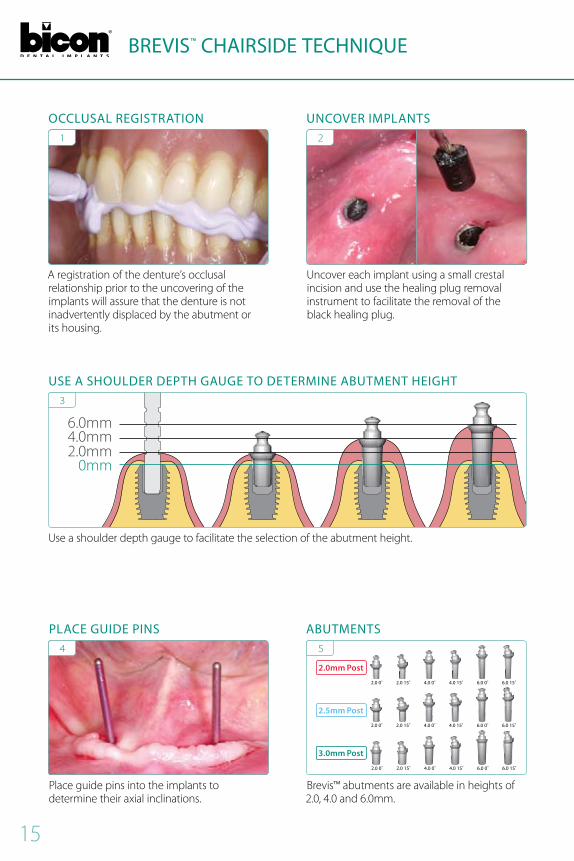
BREVIS™ CHAIRSIDE TECHNIQUE
A registration of the denture’s occlusal relationship prior to the uncovering of the implants will assure that the denture is not inadvertently displaced by the abutment or its housing
1
OCCLUSAL REgISTRATION
4.0 15˚
4.0 15˚
6.0 0˚
6.0 0˚
4.0 0˚
4.0 0˚
2.0 15˚
2.0 15˚
2.0 0˚
2.0 0˚
6.0 15˚
6.0 15˚
2.0 0˚ 6.0 15˚6.0 0˚4.0 15˚4.0 0˚2.0 15˚
2.0mm Post
2.5mm Post
3.0mm Post
5
ABUTMENTS
Brevis™ abutments are available in heights of 2 0, 4 0 and 6 0mm
uncover each implant using a small crestal incision and use the healing plug removal instrument to facilitate the removal of the black healing plug
2
UNCOVER IMPLANTS
use a shoulder depth gauge to facilitate the selection of the abutment height
USE A SHOULDER DEPTH gAUgE TO DETERMINE ABUTMENT HEIgHT
6 0mm4 0mm2 0mm
0mm
3
place guide pins into the implants to determine their axial inclinations
PLACE gUIDE PINS4

16
BREVIS™ CHAIRSIDE TECHNIQUE
place soft wax in the denture to act as a pressure indicator to determine the relative position of the abutments
7
PLACE BLUE wAx
Rotate a combination of 0˚ and/or 15˚ angled abutments to achieve parallelism prior to their being seated
6
PARALLEL ABUTMENTS
place a Brevis™ housing on each abutment intra-orally See #11
10
BREVIS™ HOUSINg
Liberally relieve denture to accommodate the Brevis™ housings Confirm clearance for housings by placing the denture over the housings
9
RELIEVE DENTURE
Alternatively, the top of the abutment may be marked with a felt tip pen to indicate the location of the abutment on the denture
8
MARk ABUTMENTS
CONTINUED NExT PAgE

17
BREVIS™ CHAIRSIDE TECHNIQUE
place the Brevis™ housings and a piece of rubber dam over the abutments to act as an apron to prevent acrylic from locking onto an abutment Ensure that the rubber dam protects the undercut of the abutment from acrylic by placing it above the shoulder of the abutment.
11
PLACE HOUSINgS
Inject flowable acrylic around the Brevis™ housings and into the relieved portions of the existing denture
13
INJECT ACRyLIC
Inject vaseline™ under the rubber dam aprons to serve as an additional precaution to prevent acrylic from locking under the abutments during the chairside pickup of the Brevis™ housings
12
INJECT VASELINE™
place the denture into the mouth and instruct patient to clench bilaterally on cotton rolls to assure proper seating of the denture.
14
ASSURE PROPER SEATINg

18
BREVIS™ CHAIRSIDE TECHNIQUE
polish the excess acrylic around the Brevis™ housings after the removal of the rubber dam
15
POLISH ExCESS ACRyLIC
Radiograph of two Bicon implants and Brevis™ abutments It is paramount that overdentures be completely tissue borne and only implant retained. If the acrylic is too viscous or only placed in the denture, it may cause displacement of the housing resulting in a misalignment of the housing and excessive wear of the rubber o-rings.
16
RADIOgRAPH
KEys To suCCEss■■ use an occlusal registration jig to prevent inadvertent displacement of the denture during the chairside technique
■■ use the 15˚ Brevis™ abutment to help achieve parallelism for non-parallel implants
■■ The denture should noT rock or pivot on the abutments or the housings
■■ Do not make a direct impression of the overdenture abutments
■■ use a rubber dam and vaseline™ to prevent locking of the denture beneath the undercut of the abutments
■■ place acrylic into a syringe for ease of use and greater control
■■ A too viscous mix of acrylic may inappropriately displace the orientation of the Brevis™ housing on the abutment
■■ It is essential for the patient to clench bilaterally on cotton rolls to ensure proper seating of the housings in the denture
■■ If the denture is too retentive, slightly relieve the inside of the o-ring lumen with a round bur
■■ A common cause of accelerated o-ring wear is a Brevis™ housing whose retentive acrylic was polymerized while the Brevis™ housing was not appropriately aligned on the abutment
noTEIf the denture is inadvertently locked onto the Brevis™ abutment, it is advisable to tap it off rather than attempting to cut it off The denture may be notched to facilitate the placement of a tapping instrument Either the denture will be removed from the abutment or the abutment will be removed from the implant
19
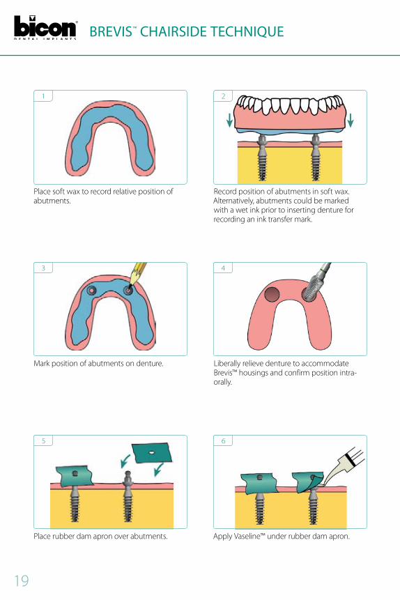
BREVIS™ CHAIRSIDE TECHNIQUE
place soft wax to record relative position of abutments
1
mark position of abutments on denture
3
place rubber dam apron over abutments
5
Record position of abutments in soft wax Alternatively, abutments could be marked with a wet ink prior to inserting denture for recording an ink transfer mark
2
Liberally relieve denture to accommodate Brevis™ housings and confirm position intra-orally
4
Apply vaseline™ under rubber dam apron
6

20
BREVIS™ CHAIRSIDE TECHNIQUE
snap Brevis™ housing onto abutments
7
place minimal acrylic into relieved denture
9
polish excess acrylic from denture
11
sufficiently apply fluid acrylic to Brevis™ housing to prevent displacement of housing upon insertion of denture
8
patient clenches bilaterally on cotton rolls while acrylic sets
10
21
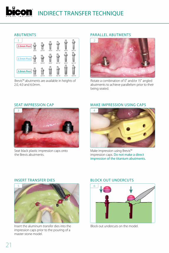
INDIRECT TRANSfER TECHNIQUE
seat black plastic impression caps onto the Brevis abutments
3
SEAT IMPRESSION CAP
Insert the aluminum transfer dies into the impression caps prior to the pouring of a master stone model
5
INSERT TRANSfER DIES
make impression using Brevis™ impression caps Do not make a direct impression of the titanium abutments.
4
MAkE IMPRESSION USINg CAPS
Block out undercuts on the model
6
BLOCk OUT UNDERCUTS
4.0 15˚
4.0 15˚
6.0 0˚
6.0 0˚
4.0 0˚
4.0 0˚
2.0 15˚
2.0 15˚
2.0 0˚
2.0 0˚
6.0 15˚
6.0 15˚
2.0 0˚ 6.0 15˚6.0 0˚4.0 15˚4.0 0˚2.0 15˚
2.0mm Post
2.5mm Post
3.0mm Post
1
ABUTMENTS
Brevis™ abutments are available in heights of 2 0, 4 0 and 6 0mm
2
PARALLEL ABUTMENTS
Rotate a combination of 0˚ and/or 15˚ angled abutments to achieve parallelism prior to their being seated
22
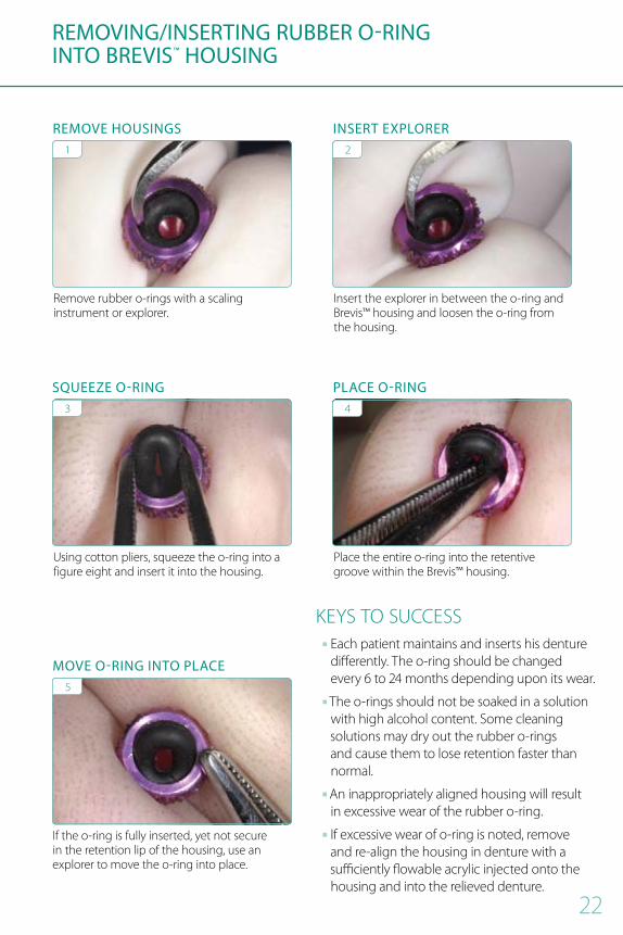
REMOVINg/INSERTINg RUBBER O-RINgINTO BREVIS™ HOUSINg
Remove rubber o-rings with a scaling instrument or explorer
1
REMOVE HOUSINgS
using cotton pliers, squeeze the o-ring into a figure eight and insert it into the housing
3
SQUEEzE O-RINg
If the o-ring is fully inserted, yet not secure in the retention lip of the housing, use an explorer to move the o-ring into place
5
MOVE O-RINg INTO PLACE
Insert the explorer in between the o-ring and Brevis™ housing and loosen the o-ring from the housing
2
INSERT ExPLORER
place the entire o-ring into the retentive groove within the Brevis™ housing
4
PLACE O-RINg
KEys To suCCEss■■ Each patient maintains and inserts his denture differently The o-ring should be changed every 6 to 24 months depending upon its wear
■■ The o-rings should not be soaked in a solution with high alcohol content some cleaning solutions may dry out the rubber o-rings and cause them to lose retention faster than normal
■■ An inappropriately aligned housing will result in excessive wear of the rubber o-ring
■■ If excessive wear of o-ring is noted, remove and re-align the housing in denture with a sufficiently flowable acrylic injected onto the housing and into the relieved denture

23
LoCAToR® ABuTmEnT sysTEm

24
LoCAToR® ABuTmEnTs* 2.0mm Post
hEIGhT DIAmETER pART numBER
1.0mm 4.0mm 260-200-501
2.0mm 4.0mm 260-200-502
3.0mm 4.0mm 260-200-503
4.0mm 4.0mm 260-200-504
5.0mm 4.0mm 260-200-505
LoCAToR® ABuTmEnTs* 3.0mm Post
hEIGhT DIAmETER pART numBER
1.0mm 4.0mm 260-300-501
2.0mm 4.0mm 260-300-502
3.0mm 4.0mm 260-300-503
4.0mm 4.0mm 260-300-504
5.0mm 4.0mm 260-300-505
LOCATOR® ABUTMENT SySTEM
*Each Locator® abutment is packaged with a male processing kit.
LoCAToR® ABuTmEnT ConsIDERATIons■■ Bicon strongly recommends the use of the Brevis abutment due to its flexibility in achieving parallelism with angled abutments.
■■ Locator® Abutments are not available in the 2.5mm Post.■■ The Locator® Attachment features a denture component with a skirt that easily locates the mating implant abutment
■■ The self-aligning ability of the attachment aids the patient in positioning their prosthesis in a similar manner as a guide plane created by a milled bar
■■ The implant retained overdenture can be properly seated without damage to the attachment components This is especially important for a patient lacking anatomical structures necessary to orient their denture due to a severely resorbed mandibular ridge

25
LOCATOR® ABUTMENT SySTEM
LoCAToR® ACCEssoRIEsDEsCRIpTIon pART numBER
Locator Male Processing kit (2) 260-100-519
2.3 kg
(5.0 lb.) Retention
Male
1.4 kg (3.0 lb.)
Retention Male
0.7 kg (1.5 lb.)
Retention Male
ProcessingMale
Metal Housing
Cap
BlockoutSpacer
Locator Extended Range green Cap (4) 260-100-521
1.4 kg (3.0 lb.)
Retention Cap
0.9 kg (2.0 lb.)
Retention Cap
0.5 kg (1.0 lb.)
Retention Cap
Locator Extended Range Orange Cap (4) 260-100-525
Locator Extended Range Red Cap (4) 260-100-526
Locator Impression kit 260-100-524
Locator Impression Cap Locator Impression Analog
Locator Core Tool 260-101-839
Locator Core Tool
LoCAToR® ABuTmEnT wITh housInG
mEAsuREmEnT GuIDEThe height of the Locator® abutment is measured from the bottom of the gold portion of the abutment to the shoulder of the Locator® abutment The available heights are 1 0, 2 0, 3 0, 4 0, or 5 0mm
0 56mm1 0mm 2 0mm 3 0mm 4 0mm 5 0mm

26
LOCATOR® CHAIRSIDE TECHNIQUE
healing plug being removed with a straight curette
1
REMOVE HEALINg PLUg
Insert and gently seat abutment
5
INSERT LOCATOR® ABUTMENT
1 0mm 2 0mm 3 0mm 4 0mm 5 0mm6 0mm4 0mm2 0mm
0mm
use depth gauge to measure and select the appropriate Locator® Abutments
3
USE A SHOULDER DEPTH gAUgE TO DETERMINE ABUTMENT HEIgHT
Guide pin inserted into the well of each implant
2
INSERT gUIDE PINS
LOCATOR® ABUTMENTS
1 0mm 1 0mm3 0mm 3 0mm2 0mm 2 0mm4 0mm 4 0mm5 0mm 5 0mm
42.0mm Post 3.0mm Post
Blockout spacer being placed over a Locator® Abutment
PLACE BLOCkOUT SPACER
CONTINUED NExT PAgE
6

27
LOCATOR® CHAIRSIDE TECHNIQUE
marker ink being placed on the housing to indicate its location relative to denture
Denture being inserted
Black ink indicating housing position Acrylic bur being used to provide room for the housing
Flowable acrylic being injected into the denture
Flowable acrylic being injected around the housing caps
1
3
5
2
4
6
MARk HOUSINg
LOCATE HOUSINg POSITION
INJECT ACRyLIC INTO DENTURE
INSERT DENTURE
PROVIDE ROOM fOR HOUSINg
INJECT ACRyLIC AROUND CAPS

28
LOCATOR® CHAIRSIDE TECHNIQUE & HOUSINg CAP
view of denture after being cleaned and polished
Denture being inserted patient applying occlusal force while metal housing caps are being secured into the denture
Removal of the processing male from the metal housing cap with Locator® Core Tool
Locator® Core Tool is being used to hold a pink 1 4 kg (3 0 lb) retention male
Insertion of a pink 1 4 kg (3 0 lb) retention male into the metal housing cap
view of housing cap with its retention male
7
1
3
8
2
4
CLEAN AND POLISH DENTURE
PROCESSINg MALE REMOVAL
INSERT RETENTION MALE
INSERT DENTURE
HOLD RETENTION MALE
ASSEMBLED CAP

29
AppEnDIX

30
IAC® POLISHINg TECHNIQUE
IAC® poLIshInG KITDEsCRIpTIon pART numBER
IAC® Polishing kit 260-103-033
1 2 3
IAC®MARk INTER- PROxIMAL CONTACTS
SILICONE PRE-POLISHINg DISk
4 5 6
PINk CERAMIC POLISHINg DISk
SILICONE CARBIDE BRUSH
DIAMOND POLISHINg PASTE
7 8 9
SOfT gOAT HAIR BRUSH COTTON BUffINg wHEEL THE POLISHED IAC®
31
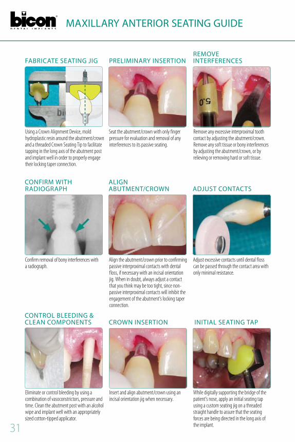
MAxILLARy ANTERIOR SEATINg gUIDE
Using a Crown Alignment Device, mold hydroplastic resin around the abutment/crown and a threaded Crown Seating Tip to facilitate tapping in the long axis of the abutment post and implant well in order to properly engage their locking taper connection .
Confirm removal of bony interferences with a radiograph .
Seat the abutment/crown with only finger pressure for evaluation and removal of any interferences to its passive seating .
Align the abutment/crown prior to confirming passive interproximal contacts with dental floss, if necessary with an incisal orientation jig . When in doubt, always adjust a contact that you think may be too tight, since non-passive interproximal contacts will inhibit the engagement of the abutment’s locking taper connection .
Remove any excessive interproximal tooth contact by adjusting the abutment/crown . Remove any soft tissue or bony interferences by adjusting the abutment/crown, or by relieving or removing hard or soft tissue .
Adjust excessive contacts until dental floss can be passed through the contact area with only minimal resistance .
fABRICATE SEATINg JIg
CONfIRM wITH RADIOgRAPH
Eliminate or control bleeding by using a combination of vasoconstrictors, pressure and time . Clean the abutment post with an alcohol wipe and implant well with an appropriately sized cotton-tipped applicator .
CONTROL BLEEDINg & CLEAN COMPONENTS
PRELIMINARy INSERTION
ALIgN ABUTMENT/CROwN
Insert and align abutment/crown using an incisal orientation jig when necessary .
CROwN INSERTION
REMOVE INTERfERENCES
ADJUST CONTACTS
While digitally supporting the bridge of the patient’s nose, apply an initial seating tap using a custom seating jig on a threaded straight handle to assure that the seating forces are being directed in the long axis of the implant .
INITIAL SEATINg TAP
32
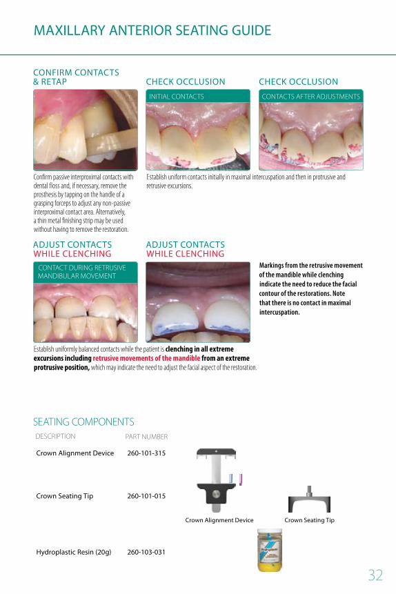
MAxILLARy ANTERIOR SEATINg gUIDE
Markings from the retrusive movement of the mandible while clenching indicate the need to reduce the facial contour of the restorations. Note that there is no contact in maximal intercuspation.
sEATInG ComponEnTsDEsCRIpTIon pART numBER
Crown Alignment Device 260-101-315
Crown Alignment Device Crown Seating Tip
Crown Seating Tip 260-101-015
Hydroplastic Resin (20g) 260-103-031
Confirm passive interproximal contacts with dental floss and, if necessary, remove the prosthesis by tapping on the handle of a grasping forceps to adjust any non-passive interproximal contact area . Alternatively, a thin metal finishing strip may be used without having to remove the restoration .
Establish uniformly balanced contacts while the patient is clenching in all extreme excursions including retrusive movements of the mandible from an extreme protrusive position, which may indicate the need to adjust the facial aspect of the restoration .
Establish uniform contacts initially in maximal intercuspation and then in protrusive and retrusive excursions .
InITIAL ConTACTs
ConTACT DuRInG RETRusIvE mAnDIBuLAR movEmEnT
CONfIRM CONTACTS & RETAP
ADJUST CONTACTS wHILE CLENCHINg
ADJUST CONTACTS wHILE CLENCHINg
CHECk OCCLUSION CHECk OCCLUSION
ConTACTs AFTER ADJusTmEnTs
33
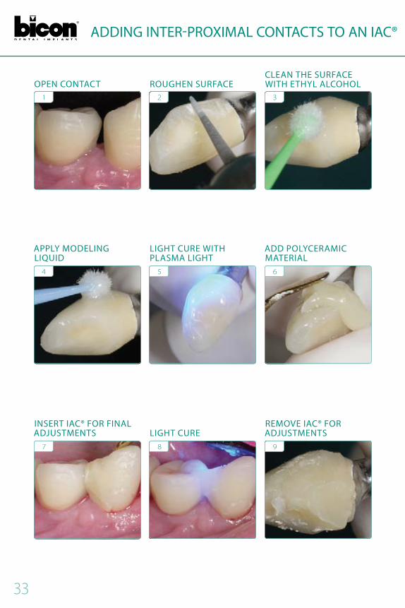
ADDINg INTER-PROxIMAL CONTACTS TO AN IAC®
1
4
7
2
5
8
3
6
9
OPEN CONTACT
APPLy MODELINg LIQUID
INSERT IAC® fOR fINAL ADJUSTMENTS
ROUgHEN SURfACE
LIgHT CURE wITH PLASMA LIgHT
LIgHT CURE
CLEAN THE SURfACE wITH ETHyL ALCOHOL
ADD POLyCERAMIC MATERIAL
REMOVE IAC® fOR ADJUSTMENTS

34
ADDINg INTER-PROxIMAL CONTACTS TO AN IAC® ADDINg INTER-PROxIMAL CONTACTS TO AN IAC®
10
13
11
14
12
15
REMOVE ExCESS MATERIAL
USE COTTON BUffINg wHEEL
USE PINk POLISHINg DISk
INSERT IAC®
USE SOfT gOAT HAIR BRUSH
CLOSED CONTACT wITH SEATED IAC®
35
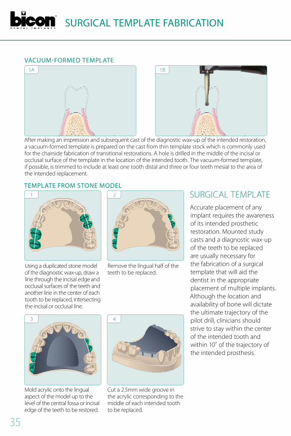
SURgICAL TEMPLATE fABRICATION
Remove the lingual half of the teeth to be replaced
Cut a 2 5mm wide groove in the acrylic corresponding to the middle of each intended tooth to be replaced
mold acrylic onto the lingual aspect of the model up to the level of the central fossa or incisal edge of the teeth to be restored
suRGICAL TEmpLATEAccurate placement of any implant requires the awareness of its intended prosthetic restoration mounted study casts and a diagnostic wax-up of the teeth to be replaced are usually necessary for the fabrication of a surgical template that will aid the dentist in the appropriate placement of multiple implants Although the location and availability of bone will dictate the ultimate trajectory of the pilot drill, clinicians should strive to stay within the center of the intended tooth and within 10˚ of the trajectory of the intended prosthesis
1A
1
3
1B
2
4
VACUUM-fORMED TEMPLATE
TEMPLATE fROM STONE MODEL
After making an impression and subsequent cast of the diagnostic wax-up of the intended restoration, a vacuum-formed template is prepared on the cast from thin template stock which is commonly used for the chairside fabrication of transitional restorations A hole is drilled in the middle of the incisal or occlusal surface of the template in the location of the intended tooth The vacuum-formed template, if possible, is trimmed to include at least one tooth distal and three or four teeth mesial to the area of the intended replacement
using a duplicated stone model of the diagnostic wax-up, draw a line through the incisal edge and occlusal surfaces of the teeth and another line in the center of each tooth to be replaced, intersecting the incisal or occlusal line

36
SURgICAL TEMPLATE fABRICATION
FABRICATIon oF pALATAL TEmpLATE FRom EXIsTInG pRosThEsIsFor larger edentulous areas, fabricate a palatal template by using an existing removable prosthesis when fabricating the palatal template, the buccal aspect is inclined from the incisal edge or central fossa of the proposed teeth back to the crest of the alveolar ridge, which is represented on a duplicated prosthesis as the greatest concavity on the alveolar ridge side of the prosthesis Insert denture into alginate in
denture duplicator
1
Fill other side with alginate Close and allow alginate to set
2 3 4
Apply separating medium
Fill alginate mold with acrylic Close and allow acrylic to set
5 6 7
open and remove denture
CONTINUED NExT PAgE

37
SURgICAL TEMPLATE fABRICATION
open and remove duplicated denture
Draw a line in the middle of each tooth and a line representing greatest concavity on the tissue side
8 9
Cut a 2 0mm wide groove in center of each tooth joining the lines representing the middle of each tooth and greatest concavity of the tissue side
Remove the buccal acrylic along the slope joining the two lines representing the middle of each tooth and greatest concavity of the tissue side
10 11
Trim excess incisal length to prevent interference with head of handpiece
Template determines mesio-distal positioning Availability of bone determines final bucco-lingual angulation
12 13
KEys To suCCEss■■ The trajectory of the pilot bur will be the trajectory of the implant and the trajectory of a straight abutment
■■ The final implant osteotomy, to the extent possible, should be centered in the middle of the intended prosthetic tooth
■■ An appropriate mesio-distal positioning of a pilot osteotomy is more critical than a slightly off-axis trajectory
■■ Both the vacuum-formed and palatal templates are placed in cold sterilization prior to their being used to facilitate achieving an appropriate trajectory for the pilot bur
0˚ 15˚

38
ABUTMENT REMOVAL TECHNIQUE
ABuTmEnT FoRCEpsDEsCRIpTIon pART numBER
Abutment Removal forceps (Upper) 260-801-055
Abutment Removal forceps (Lower) 260-801-056
SEATED ABUTMENTOPTION 1: TwIST AND PULL OPTION 2: TAP OUT
ABuTmEnT
SEATED CROwNOPTION 1: PROTECT CROwN TwIST AND PULL OPTION 2: TAP OUT
CRown

Copyright © 2014 Bicon LIT-260 R0214
world headquarters501 ArborwayBoston, MA 02130 USATEL 800.88.BICON ■ 617.524.4443FAX 800.28.BICON ■ 617.524.0096www.bicon.com ■ [email protected]