Embed Size (px)
Citation preview

Restoring DIC Microscopy Images fromMultiple Shear Directions
Zhaozheng Yin1 Dai Fei Elmer Ker2 Takeo Kanade1
1Robotics Institute, 2Department of Biological SciencesCarnegie Mellon University, Pittsburgh, US
Abstract. Differential Interference Contrast (DIC) microscopy is a non-destructiveimaging modality that has been widely used by biologists to capture microscopyimages of live biological specimens. However, as a qualitative technique, DIC mi-croscopy records specimen’s physical properties in an indirect way by mappingthe gradient of specimen’s optical path length (OPL) into the image intensity. Inthis paper, we propose to restore DIC microscopy images by quantitatively esti-mating specimen’s OPL from a collection of DIC images captured from multipleshear directions. We acquire the DIC images by rotating the specimen dish on themicroscope stage and design an Iterative Closest Point algorithm to register theimages. The shear directions of the image dataset are automatically estimated byour coarse-to-fine grid search algorithm. We develop a direct solver on a regular-ized quadratic cost function to restore DIC microscopy images. The restorationfrom multiple shear directions decreases the ambiguity among different individ-ual restorations. The restored DIC images are directly proportional to specimen’sphysical measurements, which is very amenable for microscopy image analysissuch as cell segmentation.
1 Introduction
Under a traditional brightfield microscope, living specimens such as cells are colorlessand transparent because they are predominantly phase objects that absorb and scatterlittle illumination light. That is, cells do not significantly alter the amplitude of the lightwaves passing through them and as a result, produces little or no contrast when viewedunder a brightfield microscope. For tissue culture cells, a cell’s optical path length (OPL,product of its refractive index and geometric thickness) is normally different from thatof the surrounding medium (about 0.125µm or a quarter wavelength of green light).This optical path difference induces a small phase difference between the light wavespassing through cells and those traversing the surrounding medium. Since human eyesare sensitive to amplitude differences between light waves as opposed to phase differ-ences, Differential Interference Contrast (DIC) microscopy technique was invented in1950s to convert these minute phase variations to intensity changes that can be easilydetected by human eyes (see textbook [12]).
The DIC microscope works by splitting a polarized illumination light wave intotwo component waves that are spatially displaced (sheared) along a specific direction,and then recombining the two waves after they travel through adjacent locations on the
2 Zhaozheng Yin, Dai Fei Elmer Ker, and Takeo Kanade
specimen plate. The recombination (interference) is sensitive to phase variations be-tween the two component waves. An adjustable bias (bias retardation) can be addedinto the phase variation. Because the phase variation between the two waves is causedby OPL difference at two adjacent locations, this microscopy imaging technique is thencalled “differential interference,” and the observed intensity in DIC images is propor-tional to the OPL gradient along the shear direction. The relief-like images generatedby DIC microscopy have the pseudo 3D shadow-cast effects as if the specimens areilluminated from an oblique lighting resource (e.g. Fig. 1(a,b)), but this artifact only in-dicates the orientation of a specimen’s OPL gradient rather than the real topographicalstructure.
1.1 Related Work
Since the intensity of a DIC image is not a linear mapping of specimen’s inherent prop-erties such as refractive index, thickness or OPL, this has triggered strong researchinterest in reconstructing the original physical properties of specimens from DIC im-ages. We summarize the related work in three aspects: hardware-related techniques,reconstruction from a single DIC image and reconstruction using multiple DIC images.
(1) Arnison et al. [1] proposed a hardware extension to the conventional differentialinterference by inserting an extra quarter wave plate in the optical layout of a DICmicroscope, and restored the phase objects by varying bias setting and using geometricphase-shift techniques. Shribak et al. [15] developed an orientation-independent DICmicroscopy by adding liquid crystal devices in the common DIC microscopes. Thesetup of these new optical configurations might be complicated and inaccessible to thecommon biology labs.
(2) Noticing the gradient interpretation of DIC images, line integration methodswere developed to reconstruct DIC images [8]. The line-by-line integration along sheardirection introduces new streaking artifacts in reconstructed images and it is sensitiveto gradient noise, thus Hilbert transform [2] and other ad hoc techniques such as low-pass filtering [7] were explored to reduce the streaking artifacts to a certain degree.General image processing algorithms such as deconvolution by Wiener filter [7, 11]or by Landweber iterations [6] have been applied to reconstruct optical path lengthfrom DIC images. A preconditioning approach was recently proposed in [10] wherethe DIC image is reconstructed by minimizing a nonnegative mixed-norm constrainedcost function. We reimplemented these three types of approaches and applied them on apair of DIC images of the same specimens captured from two different shear directions.As shown in Fig. 1(c) and (d), we can observe the streak artifacts by line integration.Fig. 1(e) and (f) show the unsatisfactory restoration results by Wiener filtering with 1%noise-to-signal power ratio of the additive noise. The deconvolution performance de-pends on the prior knowledge of various hardware parameters (such as shear directionsand bias setting) and image noise models. Fig. 1(g) and (h) show the reconstructionresults by the preconditioning method. It is time-consuming to estimate the direct mea-surement on specimens by the iterative preconditioning method.
From Fig. 1, we have a common observation that the reconstructions of the imagepair (Fig. 1(c,d), Fig. 1(e,f), and Fig. 1(g,h)) are not the same for the same specimens.That is, when biologists analyze specimens, they will obtain different measurements

Restoring DIC Microscopy Images from Multiple Shear Directions 3
Fig. 1. Reconstructing optical path length from DIC images. (a,b) Two DIC image of the samespecimens captured from two different shear directions (the arrow denotes the shear direction θ);(c,d) Reconstruction by line integration enhanced by low-pass filtering; (e,f) Reconstruction bydeconvolution (Wiener filtering); (g,h) Reconstruction by preconditioning.
on the specimen’s optical path length according to different shear directions. This isvery undesirable because biologist don’t know which direction-specific reconstructionunveils the real properties of specimens.
(3) A few approaches have been proposed to restore specimen’s properties frommultiple DIC images [1, 6, 9, 13, 15]. These approaches either rotate prisms, change biassettings or step the shear azimuth to capture multiple DIC images, and they require atleast two images captured from a pair of orthogonal shear directions. Without specially-designed hardware, it is hard to rotate the specimen dish or prism manually by exact 90degrees to satisfy the orthogonal requirement.
1.2 Our Proposal
We propose a novel approach to restore DIC microscopy images captured from multipleshear directions without the strict orthogonal requirement. In Section 2, we derived aclosed-form solution for the restoration. Since the DIC images were captured by man-ually rotating the dish on the stage of a common DIC microscope, there are Euclideantransformation (rotation and translation) among captured DIC images. We designed anIterative Closest Point (ICP) algorithm to register the image dataset (Section 3). Ratherthan measuring the shear directions of the DIC images manually, we propose a coarse-to-fine grid search algorithm to find the shear directions automatically (Section 4). Weshow our experiment results in Section 5 with the conclusion followed in Section 6.
2 Problem Formulation and Restoration Method
Based on the gradient interpretation of DIC images, we have the following simplifiedDIC imaging model

4 Zhaozheng Yin, Dai Fei Elmer Ker, and Takeo Kanade
Fig. 2. Estimate the optical path length in DIC images. (a) The three observed gradient signalsalong different shear directions; (b) The three signals after integration do not intersect in theOPL space (i.e. there is no consensus among the restored signals); (c) We propose to restoreDIC images (i.e. estimate the optical path length) by minimize the total distance to all integratedsignals; (d) The spatial smooth constraint (gray mesh) is considered during the restoration; (e)The restoration result using three DIC images.
g = ∇θf (1)
where g(u, v) is an observed DIC image1, ∇θ is the gradient operator along the sheardirection θ and f(u, v) is the DIC image to be restored. This imaging model is alsoused by some other DIC reconstruction methods such as the iterative preconditioningmethod [10] and deconvolution by Landweber iteration [6]. More accurate and compli-cated DIC imaging models can be referred to [14].
Based on Eq.1, the DIC image can be restored by applying line-by-line integrationon the observed gradient g along the shear direction θ
f =
∫g dxθ (2)
where xθ denotes a location on the lines along the shear direction. For a line on thespecimen plate with M locations, we can observe M − 1 gradient values by DIC mi-croscopy. The line integration method reverses the differential problem by estimatingthe OPL values at M locations from observed M − 1 gradient values, thus there aremore unknowns than available equations. The under-constrained equation system plusthe image acquisition noise may make the restored signal inconsistent when we per-form line integration along different shear directions. As shown in Fig. 2(a), at a spec-imen location, three gradient signals are extracted from three DIC images along theirshear directions. When we integrate the three gradient signals independently (Fig. 2(b)),the three reconstructed signals do not intersect in the OPL space - they have differentrestoration values on f at the same specimen location! To avoid the ambiguity andachieve the consensus among different restorations, we propose to estimate the true f
1 We drop the 2D location indices (u, v) in all the equations for concise expressions.
Restoring DIC Microscopy Images from Multiple Shear Directions 5
in a least-square sense. In other words, the real f at that location should have the mini-mum total distance to all integrated signal curves (Fig. 2(c)). Thus, we are looking foran image f to minimize
K∑i=1
∫R2
(f −∫
gi dxθi)2dx (3)
where i indexes the K DIC images captured from different shear directions θi on thesame specimens, x = (u, v) is a pixel location on the 2D Euclidean space R2. Theminimization on Eq. 3 needs to carry out the line integration
∫gi dx
θi explicitly foreach DIC image. However, the line integration itself is not a satisfactory restorationas we see in Fig. 1(c) and (d). Instead, we propose to restore f by minimizing a costfunction in the gradient domain directly
K∑i=1
∫R2
(∇θif − gi)2dx. (4)
The goal is to compute an f whose gradients along different shear directions are as closeas possible to the corresponding given gradients, gi’s. After mapping the pixel locationfrom 2D Euclidean space to a new surface defined by the K shear directions
{x = (u, v),x ∈ R2} → {θ = (θ1, θ2, · · · , θK),θ ∈ Θ} (5)
and using the commutativity of∑
and∫
operations, the cost function (Eq. 4) is con-verted into ∫
Θ
K∑i=1
(∇θif − gi)2dθ. (6)
Eq. 6 only measures the fidelity of the restoration to all the observed data. We en-hances the data fidelity with smooth and sparse regularizations and propose the follow-ing objective function for restoration
O(f) =
∫Θ
[(K∑i=1
(dθi ∗ f − gi)2
)+ ωs(a ∗ f)2 + ωrf
2
]dθ (7)
where dθ is a differential kernel along the shear direction θ, “*” is the convolution op-eration, dθi ∗ f is equivalent to ∇θif , a is a kernel for local smooth, ωs and ωr areweighting coefficients for the smooth and sparse regularizations, respectively. dθi canbe defined by a directional first-derivative-of-Gaussian kernel [10]. The smooth con-straint encourages nearby pixels to have the same restoration values (Fig. 2(d)). Forexample, we can regularize a restored pixel value to be close to the average of its neigh-boring pixels (i.e. a = [1 1 1; 1 − 8 1; 1 1 1]/8 for 8-connected neighborhood). Thel2 sparse regularization penalizes large f values and enforces the restored backgroundpixels (with equal OPL at adjacent locations) to be close to zero. A stronger sparseregularization is using l1 norm but there is no closed-form solution for that. More dis-cussions on the regularizations can be referred to the rich research work on compressivesensing [3].
The solution that minimizes Eq. 7 must satisfy the Euler-Lagrange equation

6 Zhaozheng Yin, Dai Fei Elmer Ker, and Takeo Kanade
Fig. 3. Restoring a DIC image. (a) An input image; (b) Restoration by inverse filtering; (c) Ourrestoration by minimizing a regularized cost function.
∂E
∂f−
K∑i=1
∂
∂θi
∂E
∂fθi= 0 (8)
where fθi is a shorthand notation of dθi ∗ f and E is the integrand inside Eq. 7
E =
(K∑i=1
(dθi ∗ f − gi)2
)+ ωs(a ∗ f)2 + ωrf
2. (9)
Substituting E into Eq. 8 for the differentiating, we have
2ωsa ∗ a ∗ f + 2ωrf − 2
K∑i=1
dθi ∗ (dθi ∗ f − gi) = 0. (10)
Now, applying Fourier transform, F , on both sides of this equation, we obtain
2ωsA2 · F + 2ωrF− 2
K∑i=1
D2θi · F + 2
K∑i=1
Dθi ·Gi = 0 (11)
where A = F{a}, F = F{f}, Dθi = F{dθi}, Gi = F{gi}, “·” denotes the element-wise production and D2
θi= Dθi ·Dθi . Solving Eq. 11 for F, we have
F = −(
K∑i=1
Dθi ·Gi)./(ωsA2 + ωr −
K∑i=1
D2θi). (12)
where “./” denotes the element-wise division. f is then restored by f = F−1{F}.Fig. 2(e) shows a restored result using three images with different shear directions.
For a single DIC image with shear direction θ, the direct solution is
F = −(Dθ ·G)./(ωsA2 + ωr −D2
θ). (13)
If without regularizations (ωs = ωr = 0), Eq. 13 is degraded into an inverse filtering
F = G./Dθ. (14)
However, the simple inverse filtering can not restore a correct DIC image (Fig. 3(b)),which justifies the needs of regularization. As a comparison, our restoration by Eq. 13with ωs = 0.1 and ωr = 0.001 is shown in Fig. 3(c) that is much better than the inversefiltering. Please note that the restoration from a single shear direction (Eq. 13) contains
Restoring DIC Microscopy Images from Multiple Shear Directions 7
ambiguity to measure the real specimen property thus we have derived solution (Eq. 12)to restore DIC images from multiple shear directions. Eq. 13 is only used in Algorithm2 (Section 4) for estimating the shear direction of each individual DIC image.
3 Register a Collection of DIC Images
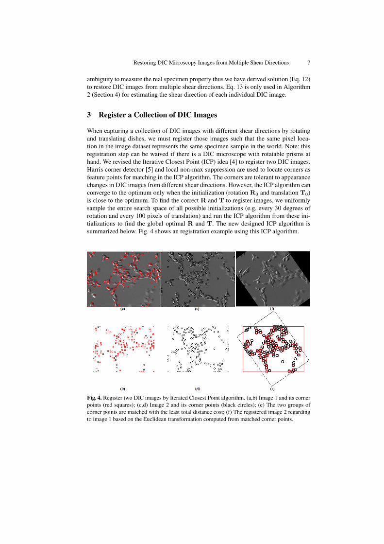
When capturing a collection of DIC images with different shear directions by rotatingand translating dishes, we must register those images such that the same pixel loca-tion in the image dataset represents the same specimen sample in the world. Note: thisregistration step can be waived if there is a DIC microscope with rotatable prisms athand. We revised the Iterative Closest Point (ICP) idea [4] to register two DIC images.Harris corner detector [5] and local non-max suppression are used to locate corners asfeature points for matching in the ICP algorithm. The corners are tolerant to appearancechanges in DIC images from different shear directions. However, the ICP algorithm canconverge to the optimum only when the initialization (rotation R0 and translation T0)is close to the optimum. To find the correct R and T to register images, we uniformlysample the entire search space of all possible initializations (e.g. every 30 degrees ofrotation and every 100 pixels of translation) and run the ICP algorithm from these ini-tializations to find the global optimal R and T. The new designed ICP algorithm issummarized below. Fig. 4 shows an registration example using this ICP algorithm.
Fig. 4. Register two DIC images by Iterated Closest Point algorithm. (a,b) Image 1 and its cornerpoints (red squares); (c,d) Image 2 and its corner points (black circles); (e) The two groups ofcorner points are matched with the least total distance cost; (f) The registered image 2 regardingto image 1 based on the Euclidean transformation computed from matched corner points.
8 Zhaozheng Yin, Dai Fei Elmer Ker, and Takeo Kanade
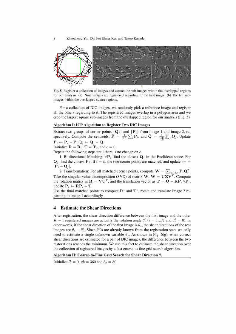
Fig. 5. Register a collection of images and extract the sub-images within the overlapped regionsfor our analysis. (a): Nine images are registered regarding to the first image. (b) The ten sub-images within the overlapped square regions.
For a collection of DIC images, we randomly pick a reference image and registerall the others regarding to it. The registered images overlap in a polygon area and wecrop the largest square sub-images from the overlapped region for our analysis (Fig. 5).
Algorithm I: ICP Algorithm to Register Two DIC Images
Extract two groups of corner points {Qj} and {Pi} from image 1 and image 2, re-spectively. Compute the centroids: P̄ = 1
|P|∑i Pi, and Q̄ = 1
|Q|∑j Qj . Update
Pi ← Pi − P̄, Qj ← Qj − Q̄.Initialize R = R0, T = T0, and c = 0.Repeat the following steps until there is no change on c.
1. Bi-directional Matching: ∀Pi, find the closest Qj in the Euclidean space. ForQj , find the closest Pk. If i = k, the two corner points are matched, and update c+ =|Pi −Qj |.
2. Transformation: For all matched corner points, compute W =∑<i,j> PiQ
Tj .
Take the singular value decomposition (SVD) of matrix W, W = UΣVT . Computethe rotation matrix as R = VUT , and the translation vector as T = Q̄ − RP̄. ∀Pi,update Pi ← RPi + T.Use the final matched points to compute R∗ and T∗, rotate and translate image 2 re-garding to image 1 accordingly.
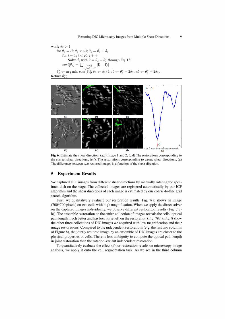
4 Estimate the Shear DirectionsAfter registration, the shear direction difference between the first image and the otherK − 1 registered images are actually the rotation angle θir (i = 1...K and θ1r = 0). Inother words, if the shear direction of the first image is θs, the shear directions of the restimages are θs − θir. Since θir’s are already known from the registration step, we onlyneed to estimate a single unknown variable θs. As shown in Fig. 6(g), when correctshear directions are estimated for a pair of DIC images, the difference between the tworestorations reaches the minimum. We use this fact to estimate the shear direction overthe collection of registered images by a fast coarse-to-fine grid search algorithm.
Algorithm II: Coarse-to-Fine Grid Search for Shear Direction θsInitialize lb = 0, ub = 360 and δθ = 30.
Restoring DIC Microscopy Images from Multiple Shear Directions 9
while δθ > 1for θs = lb; θs < ub; θs = θs + δθ
for i = 1; i < K; i+ +Solve fi with θ = θs − θir through Eq. 13;
cost[θs] =∑
i6=ji,j=1...K
|fi − fj |
θ∗s ← arg min cost[θs]; δθ ← δθ/4; lb← θ∗s − 2δθ; ub← θ∗s + 2δθ;Return θ∗s ;
Fig. 6. Estimate the shear direction. (a,b) Image 1 and 2; (c,d) The restorations corresponding tothe correct shear directions; (e,f): The restorations corresponding to wrong shear directions; (g)The difference between two restored images is a function of the shear direction.
5 Experiment Results
We captured DIC images from different shear directions by manually rotating the spec-imen dish on the stage. The collected images are registered automatically by our ICPalgorithm and the shear directions of each image is estimated by our coarse-to-fine gridsearch algorithm.
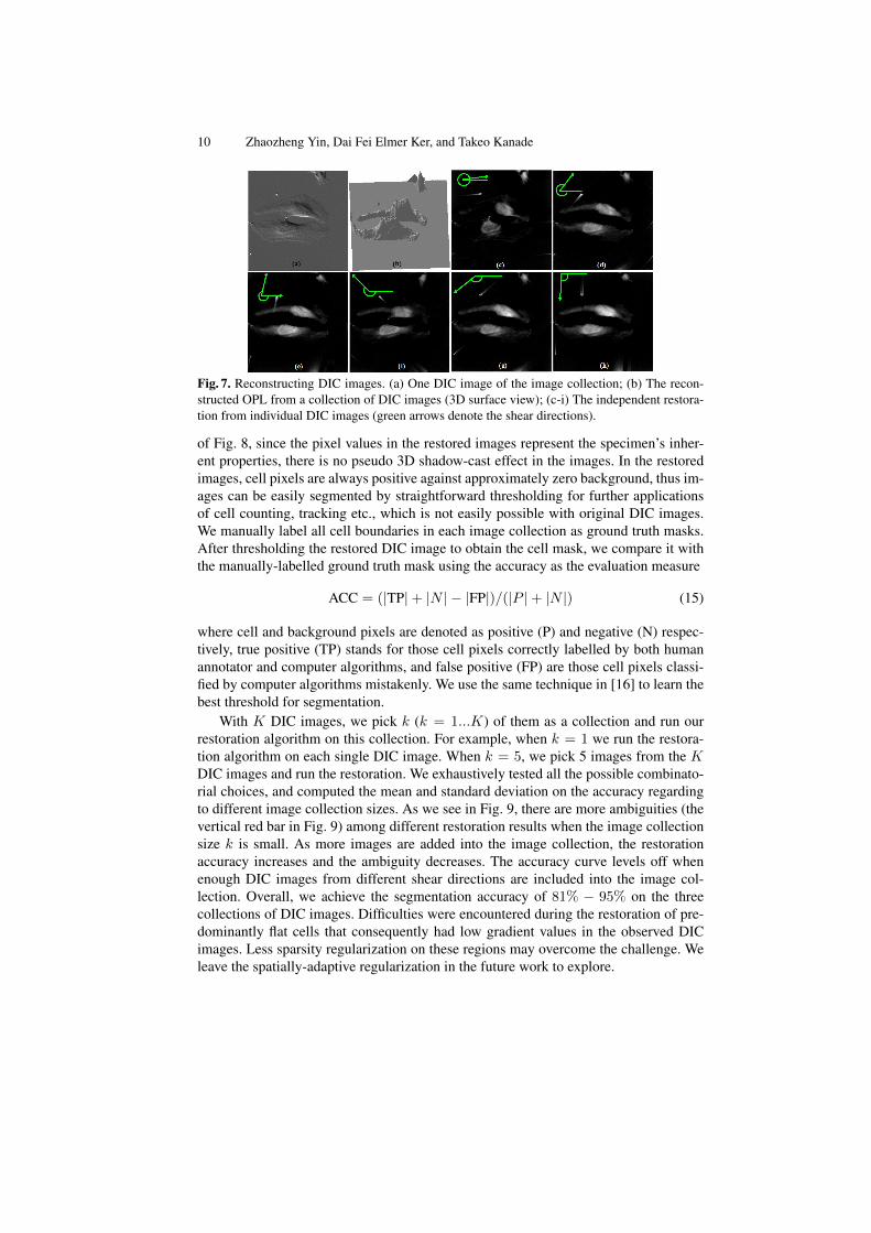
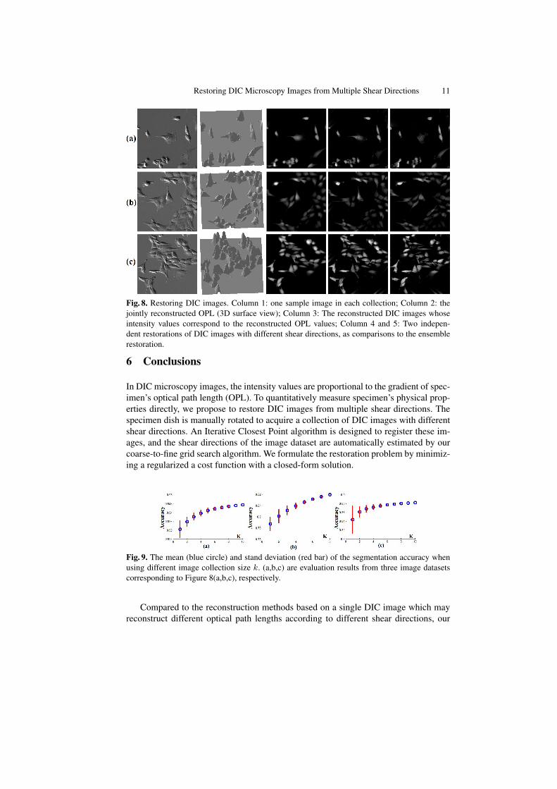
First, we qualitatively evaluate our restoration results. Fig. 7(a) shows an image(700*700 pixels) on two cells with high magnification. When we apply the direct solveron the captured images individually, we observe different restoration results (Fig. 7(c-h)). The ensemble restoration on the entire collection of images reveals the cells’ opticalpath length much better and has less noise left on the restoration (Fig. 7(b)). Fig. 8 showthe other three collections of DIC images we acquired with low magnification and theirimage restorations. Compared to the independent restorations (e.g. the last two columnsof Figure 8), the jointly restored image by an ensemble of DIC images are closer to thephysical properties of cells. There is less ambiguity to compute the optical path lengthin joint restoration than the rotation-variant independent restoration.
To quantitatively evaluate the effect of our restoration results on microscopy imageanalysis, we apply it onto the cell segmentation task. As we see in the third column
10 Zhaozheng Yin, Dai Fei Elmer Ker, and Takeo Kanade
Fig. 7. Reconstructing DIC images. (a) One DIC image of the image collection; (b) The recon-structed OPL from a collection of DIC images (3D surface view); (c-i) The independent restora-tion from individual DIC images (green arrows denote the shear directions).
of Fig. 8, since the pixel values in the restored images represent the specimen’s inher-ent properties, there is no pseudo 3D shadow-cast effect in the images. In the restoredimages, cell pixels are always positive against approximately zero background, thus im-ages can be easily segmented by straightforward thresholding for further applicationsof cell counting, tracking etc., which is not easily possible with original DIC images.We manually label all cell boundaries in each image collection as ground truth masks.After thresholding the restored DIC image to obtain the cell mask, we compare it withthe manually-labelled ground truth mask using the accuracy as the evaluation measure
ACC = (|TP|+ |N | − |FP|)/(|P |+ |N |) (15)
where cell and background pixels are denoted as positive (P) and negative (N) respec-tively, true positive (TP) stands for those cell pixels correctly labelled by both humanannotator and computer algorithms, and false positive (FP) are those cell pixels classi-fied by computer algorithms mistakenly. We use the same technique in [16] to learn thebest threshold for segmentation.
With K DIC images, we pick k (k = 1...K) of them as a collection and run ourrestoration algorithm on this collection. For example, when k = 1 we run the restora-tion algorithm on each single DIC image. When k = 5, we pick 5 images from the KDIC images and run the restoration. We exhaustively tested all the possible combinato-rial choices, and computed the mean and standard deviation on the accuracy regardingto different image collection sizes. As we see in Fig. 9, there are more ambiguities (thevertical red bar in Fig. 9) among different restoration results when the image collectionsize k is small. As more images are added into the image collection, the restorationaccuracy increases and the ambiguity decreases. The accuracy curve levels off whenenough DIC images from different shear directions are included into the image col-lection. Overall, we achieve the segmentation accuracy of 81% − 95% on the threecollections of DIC images. Difficulties were encountered during the restoration of pre-dominantly flat cells that consequently had low gradient values in the observed DICimages. Less sparsity regularization on these regions may overcome the challenge. Weleave the spatially-adaptive regularization in the future work to explore.
Restoring DIC Microscopy Images from Multiple Shear Directions 11
Fig. 8. Restoring DIC images. Column 1: one sample image in each collection; Column 2: thejointly reconstructed OPL (3D surface view); Column 3: The reconstructed DIC images whoseintensity values correspond to the reconstructed OPL values; Column 4 and 5: Two indepen-dent restorations of DIC images with different shear directions, as comparisons to the ensemblerestoration.
6 Conclusions
In DIC microscopy images, the intensity values are proportional to the gradient of spec-imen’s optical path length (OPL). To quantitatively measure specimen’s physical prop-erties directly, we propose to restore DIC images from multiple shear directions. Thespecimen dish is manually rotated to acquire a collection of DIC images with differentshear directions. An Iterative Closest Point algorithm is designed to register these im-ages, and the shear directions of the image dataset are automatically estimated by ourcoarse-to-fine grid search algorithm. We formulate the restoration problem by minimiz-ing a regularized a cost function with a closed-form solution.
Fig. 9. The mean (blue circle) and stand deviation (red bar) of the segmentation accuracy whenusing different image collection size k. (a,b,c) are evaluation results from three image datasetscorresponding to Figure 8(a,b,c), respectively.
Compared to the reconstruction methods based on a single DIC image which mayreconstruct different optical path lengths according to different shear directions, our
12 Zhaozheng Yin, Dai Fei Elmer Ker, and Takeo Kanade
method is orientation-invariant. Without the strict requirement of at least two orthog-onal shear directions as needed by the previous multiple-image-based reconstructiontechniques, our approach can restore DIC images from various shear directions. Asqualitatively and quantitatively proved by our experiments, restoration from multipleshear directions can decrease the ambiguity among different individual restorations.The restored DIC images are directly proportional to specimen’s physical measure-ments without the pseudo 3D effect, which is very amenable for microscopy imageanalysis such as cell segmentation.
Acknowledgements
We would like to thank Dr. Frederick Lanni for useful discussions and assistance withDIC microscopy. This work was supported by NIH grants RO1EB004343 & RO1EB007369.
References1. Arnison, M., Larkin, K., Sheppard, C., Smith, N., Cogswell, C.: Linear phase imaging using
differential interference contrast microscopy. J. Microsc. 214, 7–12 (2003)2. Arnison, M., Cogswell, C., Smith, N., Fekete, P., Larkin, K.: Using the hilbert transform for
3d visualization of differential interference contrast microscope images. J. Microsc. 199(1),79–84 (2000)
3. Baraniuk, R.: Compressive sensing. IEEE Sig. Proc. Mag. 24(4), 118–121 (2007)4. Besel, P., Mckay, N.: A method for registration of 3-d shapes. IEEE Trans. on Pattern Recog-
nition and Machine Intelligence 14(2), 239–256 (1992)5. Harris, C., Stephens, M.: A combined corner and edge detector. In: the 4th Alvey Vision
Conference (1988)6. Heise, B., Arminger, B.: Some aspects about quantitative reconstruction for differential in-
terference contrast (dic) microscopy. In: ICIAM07 (2007)7. Heise, B., Snnleitner, A., Klement, E.: Dic image reconstruction on large cell scans. Mi-
croscopy Research and Techniques 66, 312–320 (2005)8. Kam, Z.: Microscopic differential interference contrast image processing by line integration
(lid) and deconvolution. Bioimaging 6, 166–176 (1998)9. King, S., Libertun, A., Piestun, R., Cogswell, C.: Quantitative phase microscopy through
differential interference imaging. J. BioMed. Opt. 13, 024020 (2008)10. Li, K., Kanade, T.: Nonnegative mixed-norm preconditioning for microscopy image segmen-
tation. In: Information Processing in Medical Imaging (2009)11. Munster, E., Vliet, L., Aten, J.: Reconstruction of optical path length distributions from im-
ages obtained by a wide-field differential interference contrast microscope. J. Microsc. 188,149–157 (1997)
12. Murphy, D.: Fundamentals of Light Microscopy and Electronic Imaging. Wiley (2001)13. Preza, C.: Rotational-diversity phase estimation from differential-interference-contrast mi-
croscopy images. J. of the Opt. Soc. of America A 17(3), 415–424 (2000)14. Preza, C., Snyder, D., Conchello, J.A.: Theoretical development and experimental evaluation
of imaging models for differential interference contrast microscopy. J. Opt. Soc. Am. A16(9), 2185–2199 (1999)
15. Shribak, M., LaFountain, J., Biggs, D., Inoue, S.: Orientation-independent differential inter-ference contrast (dic) microscopy and its combination with orientation-independent polar-ization system. J. Biomed. Opt. 13(1), 014011 (2008)
16. Yin, Z., Li, K., Kanade, T., Chen, M.: Understanding the optics to aid microscopy imagesegmentation. In: Medical Image Computing and Computer Assisted Intervention (2010)