Embed Size (px)
Citation preview

Results of ITER Superconducting Magnet R&D
Peide WENG
1, Neil MITCHELL
1, Kiyoshi OKUNO
2
1 ITER Organization Cadarache, 13108 Saint Paul Lez Durance, France
2 ITER Superconducting Magnet Technology Group, JAEA, Japan
Email contact of main author: [email protected]
Abstract
The ITER magnets are among the most time-critical of the tokomak components. Over the
last two years, as well as finalising the magnet design, the final elements of the magnet R&D
have been completed. These elements include the resolution of the Nb3Sn strand performance
degradation reported for some conductor samples, the PF conductor performance
demonstration in the PF insert coil, the CS conductor jacket, the studies of radiation resistant
insulation, a basic demonstration of the performance of the uniaxial glass fibre pre-
compression rings (an important element in the TF coil out of plane support) and 68 kA HTS
current leads.
The focus of the work is now moving to qualification of components made under industrial
conditions, the qualification of processes and tooling and the fabrication process optimisation
to reduce costs. First in this respect are the fabrication routes for the TF coil radial plates and
structures, and the design/manufacture of the TF coil winding, transfer and insulation tooling.
Overall the progress in the work shows that a satisfactory performance of Nb3Sn conductor
could be reached; and the manufacture feasibility of the ITER magnet is confirmed.
1, Introduction
The ITER magnet system consists of 18 Toroidal Field (TF) coils, a 6-module Central
Solenoid (CS) coil, 6 Poloidal Field (PF) coils, 9 pairs of Correction Coils (CC) as well as 31
feeders for the magnet power, cooling and instrumentation supply[1] [2].
Both TF and CS coils operate at high fields and use Nb3Sn-type superconductor. The PF coils
and CCs use NbTi superconductor, all coils are cooled with 4.5 K supercritical helium. The
conductor is a cable-in-conduit conductor with a circular multistage cable around a small
central cooling spiral tube. The operating currents are 40-45 kA for the CS, 45-55kA for the
PF coils and 68 kA for the TF coils. The CC coils use10 kA conductor without central cooling
tube. Each coil is connected through a feeder to the current leads and valves located outside
the main cryostat and bio-shield in the coil terminal boxes (CTBs), ITER has a total of 60
current leads using high temperature superconductor (HTS).The R&D for ITER magnet
technology, especially the conductor development has been ongoing for years.
2, TF conductor
The TF and CS model coils were the most important ITER magnet R&D activity, successfully
completed and tested at the end of the EDA in 2000-2003. The model coil program showed
that, although Nb3Sn conductors could provide the required performance, there was some
degradation of the strand performance within the cable, which needed to be addressed. The
ITER conductors were modified accordingly to provide an extra margin to compensate the
degradation. However, following this, some short sample measurements seemed to show a
more dramatic fall off in performance compared to strand behaviour and the degradation
increasing with cycling. The degradation is clearly related to transverse loads on cables, either
local or cumulative.

An urgent R&D programme was launched in 2006 and carried out by CN, EU, KO, JA, RF,
US DAs as well as directly funded IO contracts PSI/CRPP in the last two years. The main
objectives of the program are: -1- to investigate early results that suggest TF conductor will
not meet performance requirements, and -2- to confirm that the TF conductor can provide the
required performance under the applied operating conditions (especially as regards magnetic
loads).
The degradation has been traced to filament fracture under the local and cumulative magnetic
loads in the cable. Tests on strands to simulate loads in cables have been done by Twente
University and the effect of bending and pinching was investigated. The results of strands
from different suppliers show a wide variation in sensitivity with the internal tin strand
appearing more sensitive. Work by FSU confirmed the correlation with filament fracture.
Further investigations of the problems found in short samples suggest that these are
sometimes related to the sample itself rather than the conductor design. Between 2006 and
2008 a large database of conductor tests (both full-size ITER and sub-size) clearly indicate
that large SULTAN samples are sensitive to the joint current distribution, even if the joint
resistance is low overall, and this effect is sufficient in some cases to result in an incorrect
degradation assessment. The biggest accomplishment in TF conductor R&D during the last
two years, however, is that it was clearly shown that long twist pitches can improve conductor
performance. The cable design has therefore been adjusted with longer twist pitch in the inner
cabling stages, while at the same time, the sample joint was improved by solder filling. The
instrumentation of the SULTAN sample was also modified in order to provide a better base
for both the electrical and calorimetric assessments of Tcs. Up to now, 9 prototype TF
conductor samples (with 18 different conductor legs) have been tested. Fig. 1 shows the test
results of SULTAN samples, the V pair (No1-3) is for the samples tested earlier and V star
(No4-8) is the result with the modified instrumentation. The poor performance of sample 6
was caused by an obvious mistake in sample preparation. Sufficient ‘good samples’ were
found to demonstrate that all strands perform adequately in the reference configurations with
margin (i.e. target Tcs >6 K, required 5.7 K). Fig 2 shows a sample Tcs change with the
cycling load [2] [3].
New analysis codes able to simulate the impact of the joints were developed. However, since
the joint non-uniformity is not known, it is not possible to reconstruct the sc performance of a
sample distorted by current non-uniformity. All “suspicious” samples are being remade with
new joints and are being re-tested.
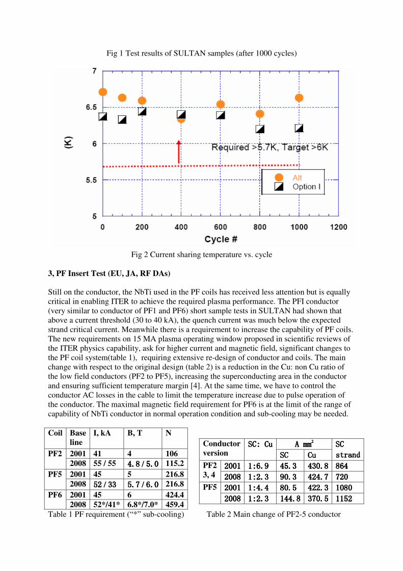
Fig 1 Test results of SULTAN samples (after 1000 cycles)
Fig 2 Current sharing temperature vs. cycle
3, PF Insert Test (EU, JA, RF DAs)
Still on the conductor, the NbTi used in the PF coils has received less attention but is equally
critical in enabling ITER to achieve the required plasma performance. The PFI conductor
(very similar to conductor of PF1 and PF6) short sample tests in SULTAN had shown that
above a current threshold (30 to 40 kA), the quench current was much below the expected
strand critical current. Meanwhile there is a requirement to increase the capability of PF coils.
The new requirements on 15 MA plasma operating window proposed in scientific reviews of
the ITER physics capability, ask for higher current and magnetic field, significant changes to
the PF coil system(table 1), requiring extensive re-design of conductor and coils. The main
change with respect to the original design (table 2) is a reduction in the Cu: non Cu ratio of
the low field conductors (PF2 to PF5), increasing the superconducting area in the conductor
and ensuring sufficient temperature margin [4]. At the same time, we have to control the
conductor AC losses in the cable to limit the temperature increase due to pulse operation of
the conductor. The maximal magnetic field requirement for PF6 is at the limit of the range of
capability of NbTi conductor in normal operation condition and sub-cooling may be needed.
Coil Base
line
I, kA B, T N
2001 41 4 106 PF2
2008 55 / 55 4.84.84.84.8 / 5.05.05.05.0 115.2
2001 45 5 216.8 PF5
2008 55552222 / 33333333 5.75.75.75.7 / 6.06.06.06.0 216.8
2001 45 6 424.4 PF6
2008 52*/41* 6.8*/7.0* 459.4
Table 1 PF requirement (“*” sub-cooling) Table 2 Main change of PF2-5 conductor
A mmA mmA mmA mm
2222 Conductor
version SCSCSCSC:::: CuCuCuCu
SCSCSCSC CuCuCuCu
SC SC SC SC
strandstrandstrandstrand
2001200120012001 1:6.91:6.91:6.91:6.9 45.345.345.345.3 430.8430.8430.8430.8 864864864864 PF2
3, 4 2008200820082008 1:2.31:2.31:2.31:2.3 90.390.390.390.3 424.7424.7424.7424.7 720720720720
2001200120012001 1:4.41:4.41:4.41:4.4 80.580.580.580.5 422.3422.3422.3422.3 1080108010801080 PF5
2008200820082008 1:2.31:2.31:2.31:2.3 144.8144.8144.8144.8 370.5370.5370.5370.5 1152115211521152
The Poloidal Field Conductor Insert (PFI) coil is a single layer solenoid completed in 2007
and tested in the bore of the CSMC facility (Fig.3) in Naka in July 2008 [5]. This insert coil
tested a long length of conductor very close to that used in the PF1 and PF6 coils as a
demonstration of the conductor and joint technology that will be applied to the ITER PF coils
and to confirm that the design margin for these coils is adequate to achieve the peak PF6
operating conditions and that the AC losses fall within the expected range of values.
The test programme includes the characterization of the conductor DC and AC performances
at the PF1 and PF6 operating conditions, the tracking of sudden quenches, the intermediate
joint resistance and the AC loss characteristics of the conductor and variations with cycling.
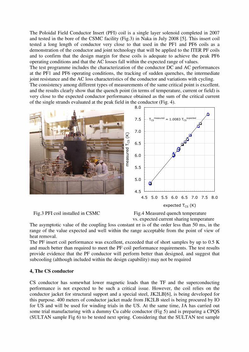
The consistency among different types of measurements of the same critical point is excellent.
and the results clearly show that the quench point (in terms of temperature, current or field) is
very close to the expected conductor performance obtained as the sum of the critical current
of the single strands evaluated at the peak field in the conductor (Fig. 4).
Fig.3 PFI coil installed in CSMC Fig.4 Measured quench temperature
vs. expected current sharing temperature
The asymptotic value of the coupling loss constant nτ is of the order less than 50 ms, in the
range of the value expected and well within the range acceptable from the point of view of
heat removal.
The PF insert coil performance was excellent, exceeded that of short samples by up to 0.5 K
and much better than required to meet the PF coil performance requirements. The test results
provide evidence that the PF conductor will perform better than designed, and suggest that
subcooling (although included within the design capability) may not be required
4, The CS conductor
CS conductor has somewhat lower magnetic loads than the TF and the superconducting
performance is not expected to be such a critical issue. However, the coil relies on the
conductor jacket for structural support and a special steel, JK2LB[6], is being developed for
this purpose. 400 meters of conductor jacket made from JK2LB steel is being procured by IO
for US and will be used for winding trials in the US. At the same time, JA has carried out
some trial manufacturing with a dummy Cu cable conductor (Fig 5) and is preparing a CPQS
(SULTAN sample Fig 6) to be tested next spring. Considering that the SULTAN test sample
TCSmeasured = 1.0083 TCS
expected
4.5
5.0
5.5
6.0
6.5
7.0
7.5
8.0
4.5 5.0 5.5 6.0 6.5 7.0 7.5 8.0
expected TCS (K)
measured TCS (K)

can not simulate the hoop strain effect, IO (in agreement with JA and US) is proposing a
modification of the CSMC facility at JAEA to test conductor loops and to enable simulation
of hoop strain effects.
Fig 6 CS cable
Fig.5 CS dummy conductor
5, Radiation Resistant Insulation (EUDA, ATI, CEA)
On the insulation, we well know that the epoxy resin is at the limits of its radiation resistance
at the ITER fluence level of 10 MGy (1022
n/m2) therefore a new radiation resistant resin
based on Cyanate ester has been selected for the TF coils and large scale impregnation trials
are underway to demonstrate its compatibility with industrial usage. This resin will provide a
radiation life of over 20MGy, twice the original ITER requirement. The Cyanate ester resins
are expensive but the cost could be reduced by blending with epoxy.
There are two main R&D issues:-1- the incorrect curing of cyanate ester can lead to
exothermic runaway reaction, and -2- the pot life of the resin is very important for the
impregnation quality of big size ITER coils. The resin should have enough fluidity and 24-48
hours pot life is required. Impregnation of a TF winding section under industrial conditions
has been performed to demonstrate that the reaction can be controlled (Fig 7). The sample
fabrication shows that the high steel to resin ratio makes exothermic reaction easy to control,
and the pot life of blended CE can be unlimited practically. The characterization of epoxy –
CE blend samples shows that blended CE (60 %CE, 40% epoxy) can offer the same radiation
resistance, and achieve about two times the ITER design basis with much lower price [7]. Fig
8 shows the Epoxy and Ep oxy -Cyanate Ester Blends radiation resistance test results.
Radiation resistance of insulation materials
in 90° direction to glass-Kapton wrapping
0
50
100
150
200
250
300
350
0 5E+21 1E+22 1,5E+22 2E+22
Accumulated neutron fluence (E>0.1 MeV) [m-²]
UTS 90°
[MPa]
pure CE (T1)
CE/DGEBF 40/60 (T2)
CE/DGEBF 30/70 (T8)
CE/DGEBF 20/80 (T10)
DGEBA Orlitherm (T6)
(Tension)

Fig. 7 Epoxy-CE blend sample Fig. 8 Epxoy-Cyanate Ester blends radiation resistance
6. Precompression Ring R&D (EU and ENEA Frascati)
A critical element of the TF coil structural support system are the pre-compression rings that
are used to pre-compress the poloidal keys at top and bottom of the inner straight leg of the
TF coils, suppressing gap opening and greatly reducing the cyclic fatigue stresses. These rings
are made of impregnated uniaxial glass fibre and are pretensioned at room temperature up to
about 300-400MPa.
Two subsize (1/5 scale) rings (Fig. 9) have been tested [8]. The tests have shown failure at
stresses well above 1200 MPa, much higher than the design value of 440MPa (Fig 10), and no
creep over 120 days at room temperature at stress levels of 990 MPa. After that, the
manufacturing procedure was optimised, and five more rings under fabrication. Higher failure
stress is expected
Fig. 9 Subsize pre-compression ring Fig. 10 Test results of R2 ring
7. R&D of TF coil manufacture
The manufacturing optimisation has focused on the TF coil winding, the TF coil radial plates
and the TF coil structures. A radial plate is a 14 m × 9 m D-shaped plate having a groove for
the conductor on each surface, made of 316LN steel. Tight requirements on dimensional
accuracy are required, for example, a flatness of 2 mm over the entire plate. A full scale
demonstration on the radial plates manufacturing [9] has been started with industry. In the
manufacturing procedures developed so far, seven segments are either machined separately
using small milling machines, or formed by laser welding of extruded profiles, and then
assembled together by a laser welding machine to form a complete radial plate (fig. 11). The
conductor has to be wound to the shape of the groove in the plate with a high degree of
accuracy, to enable it to be fitted. A winding machine which achieves the required accuracy
has been manufactured and tested. Industrial development of appropriate combinations of
forging, welding and machining to minimise costs of the massive steel structures around the
winding pack are underway.
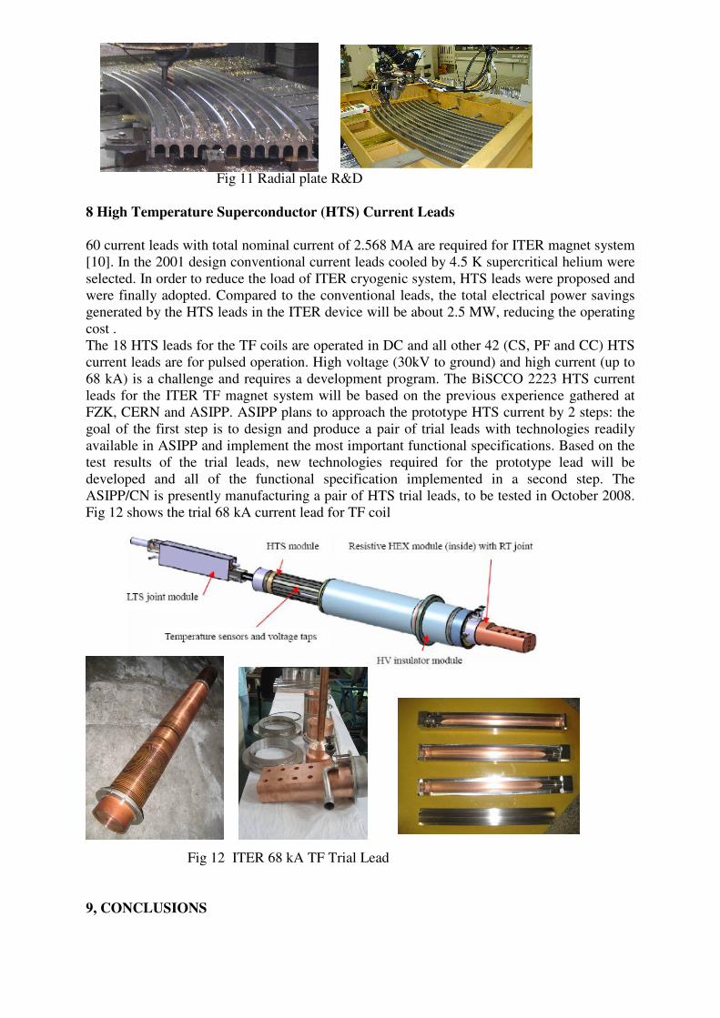
Fig 11 Radial plate R&D
8 High Temperature Superconductor (HTS) Current Leads
60 current leads with total nominal current of 2.568 MA are required for ITER magnet system
[10]. In the 2001 design conventional current leads cooled by 4.5 K supercritical helium were
selected. In order to reduce the load of ITER cryogenic system, HTS leads were proposed and
were finally adopted. Compared to the conventional leads, the total electrical power savings
generated by the HTS leads in the ITER device will be about 2.5 MW, reducing the operating
cost .
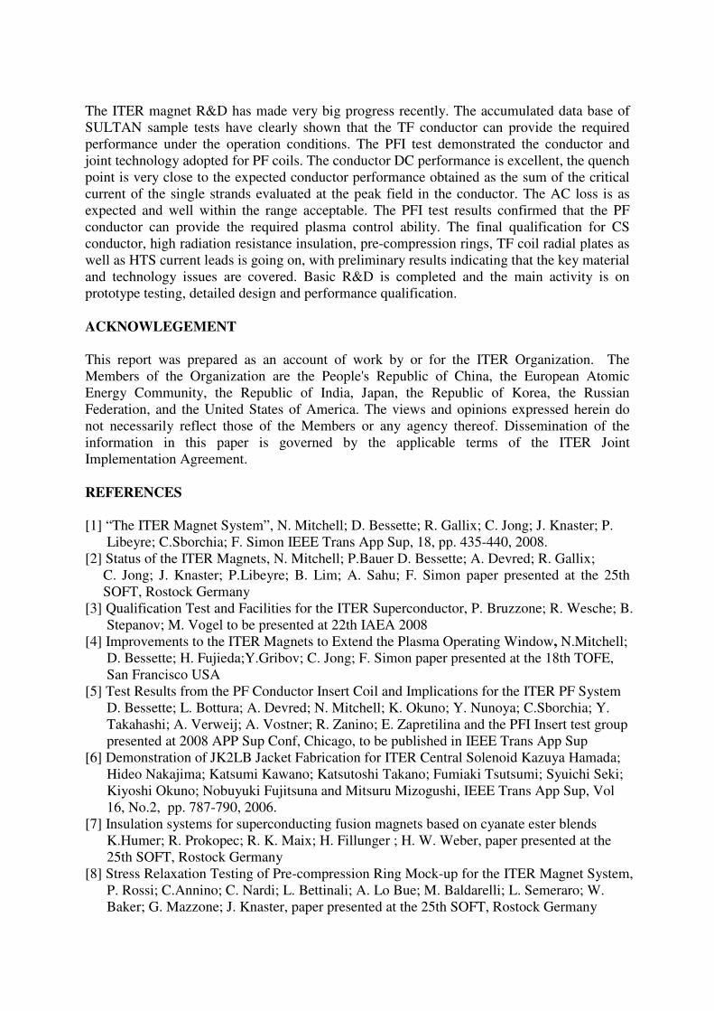
The 18 HTS leads for the TF coils are operated in DC and all other 42 (CS, PF and CC) HTS
current leads are for pulsed operation. High voltage (30kV to ground) and high current (up to
68 kA) is a challenge and requires a development program. The BiSCCO 2223 HTS current
leads for the ITER TF magnet system will be based on the previous experience gathered at
FZK, CERN and ASIPP. ASIPP plans to approach the prototype HTS current by 2 steps: the
goal of the first step is to design and produce a pair of trial leads with technologies readily
available in ASIPP and implement the most important functional specifications. Based on the
test results of the trial leads, new technologies required for the prototype lead will be
developed and all of the functional specification implemented in a second step. The
ASIPP/CN is presently manufacturing a pair of HTS trial leads, to be tested in October 2008.
Fig 12 shows the trial 68 kA current lead for TF coil
Fig 12 ITER 68 kA TF Trial Lead
9, CONCLUSIONS
The ITER magnet R&D has made very big progress recently. The accumulated data base of
SULTAN sample tests have clearly shown that the TF conductor can provide the required
performance under the operation conditions. The PFI test demonstrated the conductor and
joint technology adopted for PF coils. The conductor DC performance is excellent, the quench
point is very close to the expected conductor performance obtained as the sum of the critical
current of the single strands evaluated at the peak field in the conductor. The AC loss is as
expected and well within the range acceptable. The PFI test results confirmed that the PF
conductor can provide the required plasma control ability. The final qualification for CS
conductor, high radiation resistance insulation, pre-compression rings, TF coil radial plates as
well as HTS current leads is going on, with preliminary results indicating that the key material
and technology issues are covered. Basic R&D is completed and the main activity is on
prototype testing, detailed design and performance qualification.
ACKNOWLEGEMENT
This report was prepared as an account of work by or for the ITER Organization. The
Members of the Organization are the People's Republic of China, the European Atomic
Energy Community, the Republic of India, Japan, the Republic of Korea, the Russian
Federation, and the United States of America. The views and opinions expressed herein do
not necessarily reflect those of the Members or any agency thereof. Dissemination of the
information in this paper is governed by the applicable terms of the ITER Joint
Implementation Agreement.
REFERENCES
[1] “The ITER Magnet System”, N. Mitchell; D. Bessette; R. Gallix; C. Jong; J. Knaster; P.
Libeyre; C.Sborchia; F. Simon IEEE Trans App Sup, 18, pp. 435-440, 2008.
[2] Status of the ITER Magnets, N. Mitchell; P.Bauer D. Bessette; A. Devred; R. Gallix;
C. Jong; J. Knaster; P.Libeyre; B. Lim; A. Sahu; F. Simon paper presented at the 25th
SOFT, Rostock Germany
[3] Qualification Test and Facilities for the ITER Superconductor, P. Bruzzone; R. Wesche; B.
Stepanov; M. Vogel to be presented at 22th IAEA 2008
[4] Improvements to the ITER Magnets to Extend the Plasma Operating Window, N.Mitchell;
D. Bessette; H. Fujieda;Y.Gribov; C. Jong; F. Simon paper presented at the 18th TOFE,
San Francisco USA
[5] Test Results from the PF Conductor Insert Coil and Implications for the ITER PF System
D. Bessette; L. Bottura; A. Devred; N. Mitchell; K. Okuno; Y. Nunoya; C.Sborchia; Y.
Takahashi; A. Verweij; A. Vostner; R. Zanino; E. Zapretilina and the PFI Insert test group
presented at 2008 APP Sup Conf, Chicago, to be published in IEEE Trans App Sup
[6] Demonstration of JK2LB Jacket Fabrication for ITER Central Solenoid Kazuya Hamada;
Hideo Nakajima; Katsumi Kawano; Katsutoshi Takano; Fumiaki Tsutsumi; Syuichi Seki;
Kiyoshi Okuno; Nobuyuki Fujitsuna and Mitsuru Mizogushi, IEEE Trans App Sup, Vol
16, No.2, pp. 787-790, 2006.
[7] Insulation systems for superconducting fusion magnets based on cyanate ester blends
K.Humer; R. Prokopec; R. K. Maix; H. Fillunger ; H. W. Weber, paper presented at the
25th SOFT, Rostock Germany
[8] Stress Relaxation Testing of Pre-compression Ring Mock-up for the ITER Magnet System,
P. Rossi; C.Annino; C. Nardi; L. Bettinali; A. Lo Bue; M. Baldarelli; L. Semeraro; W.
Baker; G. Mazzone; J. Knaster, paper presented at the 25th SOFT, Rostock Germany
[9] Manufacturing Study and Trial Fabrication of Radial Plate for ITER Toroidal Field Coil
K. Abe; H. Nakajima; K. Hamada; K. Okuno; H. Yamaoka and N. Maruyama, IEEE
Trans App Sup, Vol 16, No.2, pp. 807-810, 2006.
[10] R&D Towards HTS Current Leads for ITER, Pierre Bauer; Yanfang Bi; Anyi Cheng;
Arnaud Devred; Kaisong Ding; Xiongyi Huang; Kun Lu; Neil Mitchell; Ananta K. Sahu;
Guang Shen; Yuntao Song; Tingzhi Zhou presented at 2008 App Sup Conf, Chicago, to be
published in IEEE Trans App Sup