Embed Size (px)
DESCRIPTION
Results of the run with the new electronics. A.Kuzmin, Yu.Usov, V.Shebalin, B.Shwartz. New electronics configuration New electronics in the experiment Results on the consistency, timing and noise reduction. Operation without injection veto. New+ ECL electronics. New electronics. - PowerPoint PPT Presentation
Citation preview
Dec.11, 2008 ECL parallel session, Super B 1
Results of the run with the new electronics
A.Kuzmin, Yu.Usov, V.Shebalin, B.Shwartz
1. New electronics configuration
2. New electronics in the experiment
3. Results on the consistency, timing and noise reduction.
4. Operation without injection veto.
Dec.11, 2008 ECL parallel session, Super B 2
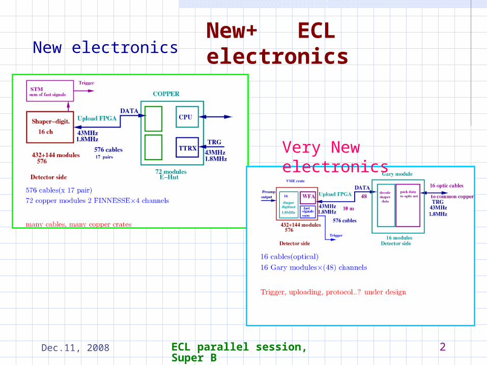
New+ ECL electronicsNew electronics
Very New electronics
Dec.11, 2008 ECL parallel session, Super B 3
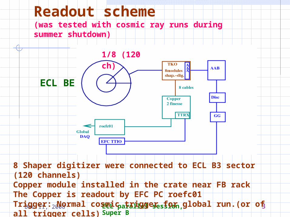
Readout scheme(was tested with cosmic ray runs during summer shutdown)
8 Shaper digitizer were connected to ECL B3 sector (120 channels)Copper module installed in the crate near FB rackThe Copper is readout by EFC PC roefc01Trigger: Normal cosmic trigger for global run.(or of all trigger cells)
ECL BE
1/8 (120 ch)
Dec.11, 2008 ECL parallel session, Super B 4
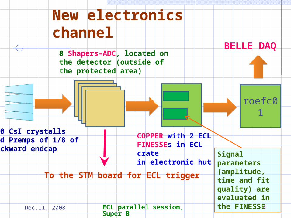
New electronics channel
8 Shapers-ADC, located on the detector (outside of the protected area)
120 CsI crystalls and Premps of 1/8 ofbackward endcap
COPPER with 2 ECL FINESSEs in ECL crate in electronic hut
roefc01
BELLE DAQ
To the STM board for ECL trigger
Signal parameters (amplitude, time and fit quality) are evaluated in the FINESSE
Dec.11, 2008 ECL parallel session, Super B 5
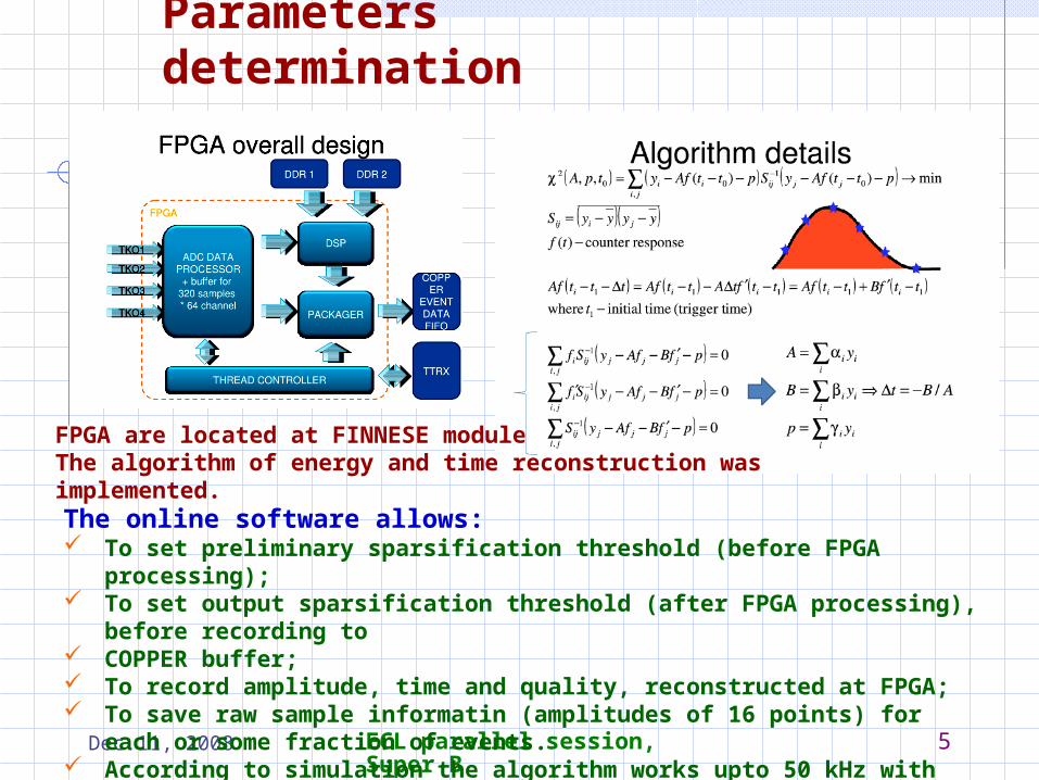
Parameters determination
FPGA are located at FINNESE moduleThe algorithm of energy and time reconstruction was implemented.
The online software allows: To set preliminary sparsification threshold (before FPGA processing); To set output sparsification threshold (after FPGA processing), before recording to COPPER buffer; To record amplitude, time and quality, reconstructed at FPGA; To save raw sample informatin (amplitudes of 16 points) for each or some fraction of
events. According to simulation the algorithm works upto 50 kHz with occupancy < 1=3.
Dec.11, 2008 ECL parallel session, Super B 6
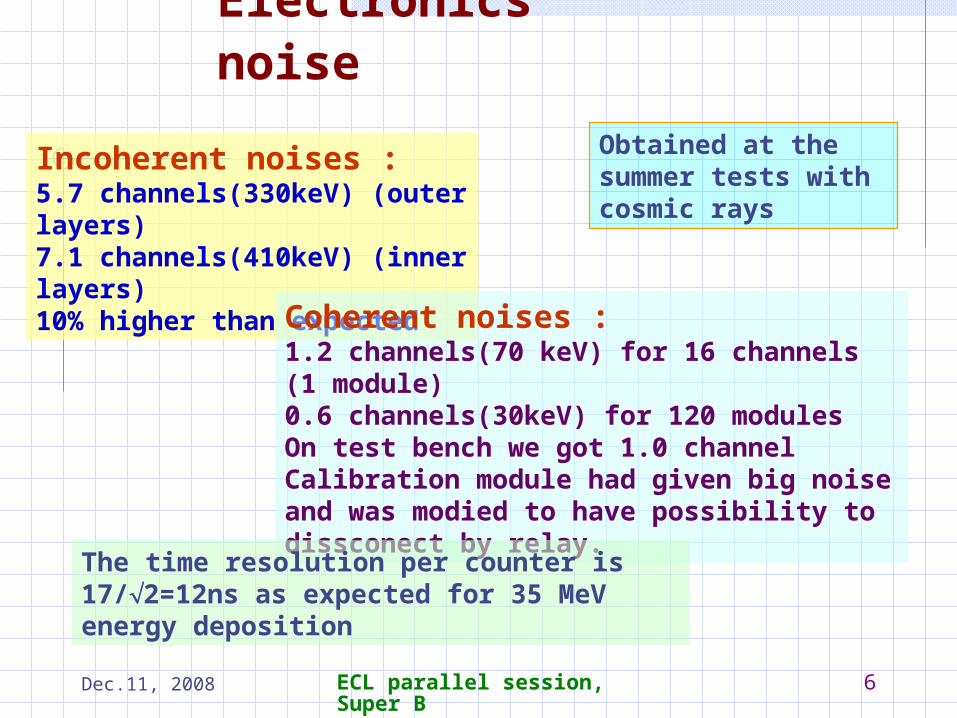
Electronics noise
Incoherent noises :5.7 channels(330keV) (outer layers)7.1 channels(410keV) (inner layers)10% higher than expected
Coherent noises :1.2 channels(70 keV) for 16 channels (1 module)0.6 channels(30keV) for 120 modulesOn test bench we got 1.0 channelCalibration module had given big noise and was modied to have possibility to dissconect by relay.
The time resolution per counter is 17/2=12ns as expected for 35 MeV energy deposition
Obtained at the summer tests with cosmic rays
Dec.11, 2008 ECL parallel session, Super B 7
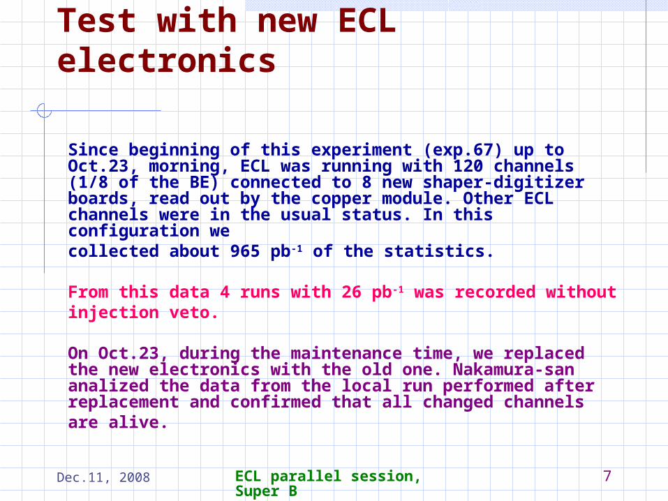
Test with new ECL electronics
Since beginning of this experiment (exp.67) up to Oct.23, morning, ECL was running with 120 channels (1/8 of the BE) connected to 8 new shaper-digitizer boards, read out by the copper module. Other ECL channels were in the usual status. In this configuration wecollected about 965 pb-1 of the statistics.
From this data 4 runs with 26 pb-1 was recorded withoutinjection veto.
On Oct.23, during the maintenance time, we replaced the new electronics with the old one. Nakamura-san analized the data from the local run performed after replacement and confirmed that all changed channelsare alive.
Dec.11, 2008 ECL parallel session, Super B 8
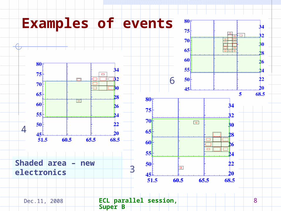
Examples of events
4
6
3Shaded area – new electronics
Dec.11, 2008 ECL parallel session, Super B 9
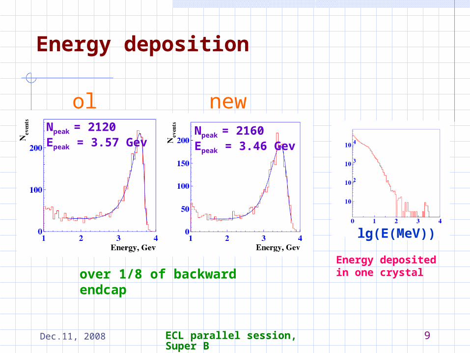
Energy deposition
newoldNpeak = 2120Epeak = 3.57 Gev
Npeak = 2160Epeak = 3.46 Gev
over 1/8 of backward endcap
lg(E(MeV))
Energy deposited in one crystal
Dec.11, 2008 ECL parallel session, Super B 10
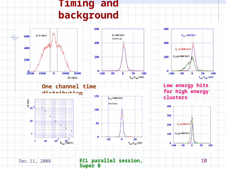
Timing and background
One channel time distribution Low energy hits for high energy clusters
Dec.11, 2008 ECL parallel session, Super B 11
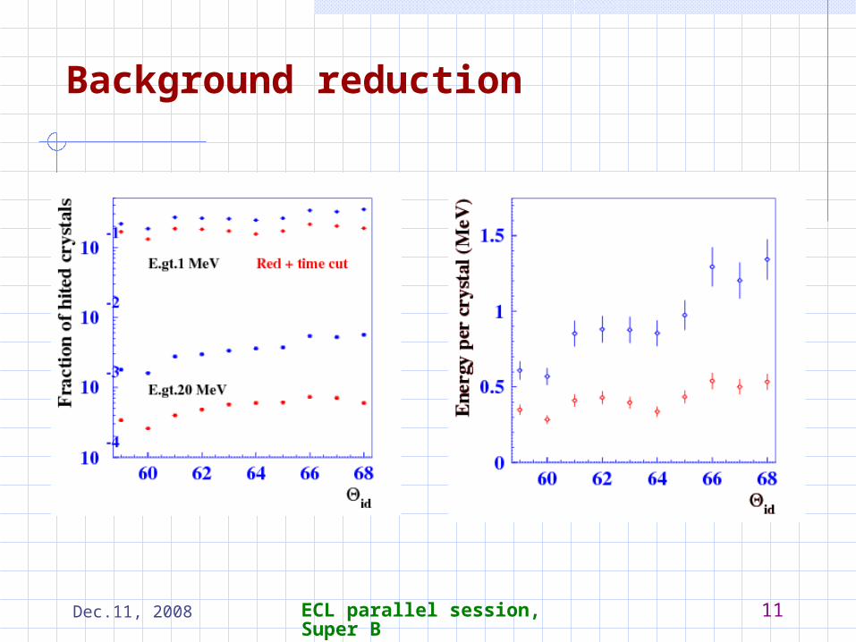
Background reduction
Dec.11, 2008 ECL parallel session, Super B 12
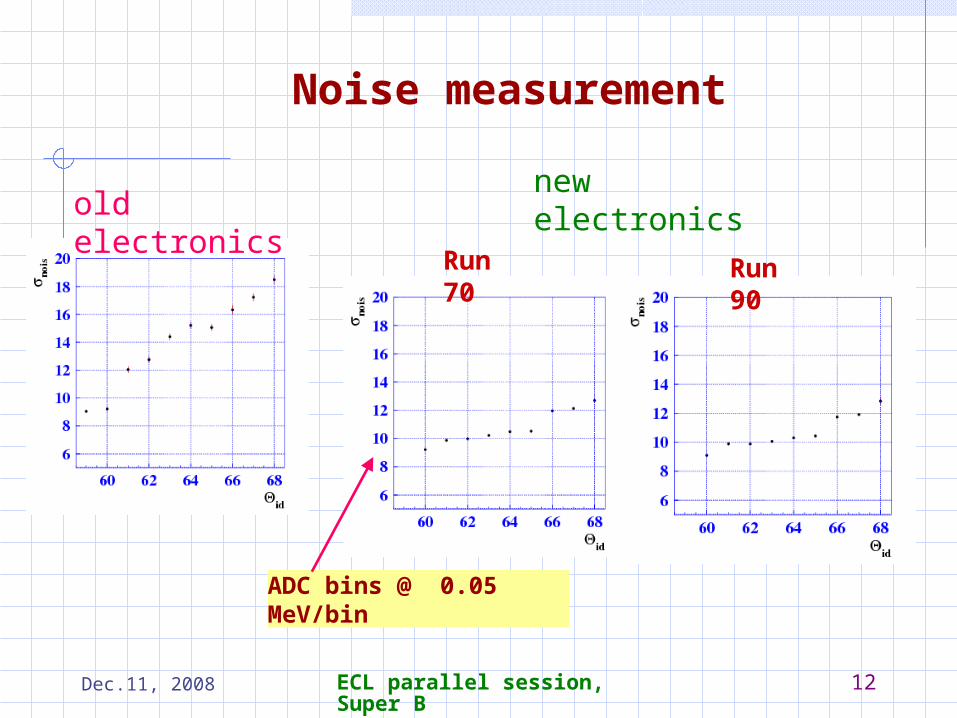
Noise measurement
old electronicsnew electronics
Run 70 Run 90
ADC bins @ 0.05 MeV/bin

Dec.11, 2008 ECL parallel session, Super B 13
Injection studyHER
LER
all
HER
all events
FE.and.BE
bad inj.time
old
new

Dec.11, 2008 ECL parallel session, Super B 14
Summary of the new electronics tests and plans System works and allows to record data from COPPER
The data evaluated by FINNESSE are consistent with that taken by the old electronics
The recorded data shows parameters close to expected.
Data quality vs. injection time are studied. A decrease of veto gate looks to be possible.
Plans: Further study pile-up noise suppression
To analyse data with sampling storage to get information about time noise correlation, as well as fit procedure and hardware reliability.
To analyse run without injection veto.
Implementation of the data from the new electronics to the standard data processing procedures: cluster reconstruction, Bhabha calibration etc.
Dec.11, 2008 ECL parallel session, Super B 15
Shaper ADC18 bit
Fast shaper
Vref.
PA
ADC
XILINX CYCLONE
DDR
DeSer.
Ser
control1
2
ALTERA
Parallel data
Serial data
215
Temperature
Fast out
DATA
1
16
1
16
16
Control
SHAPER-ADC
(temporarily)
3
15
14
13
2
Clock,Trigger
1010
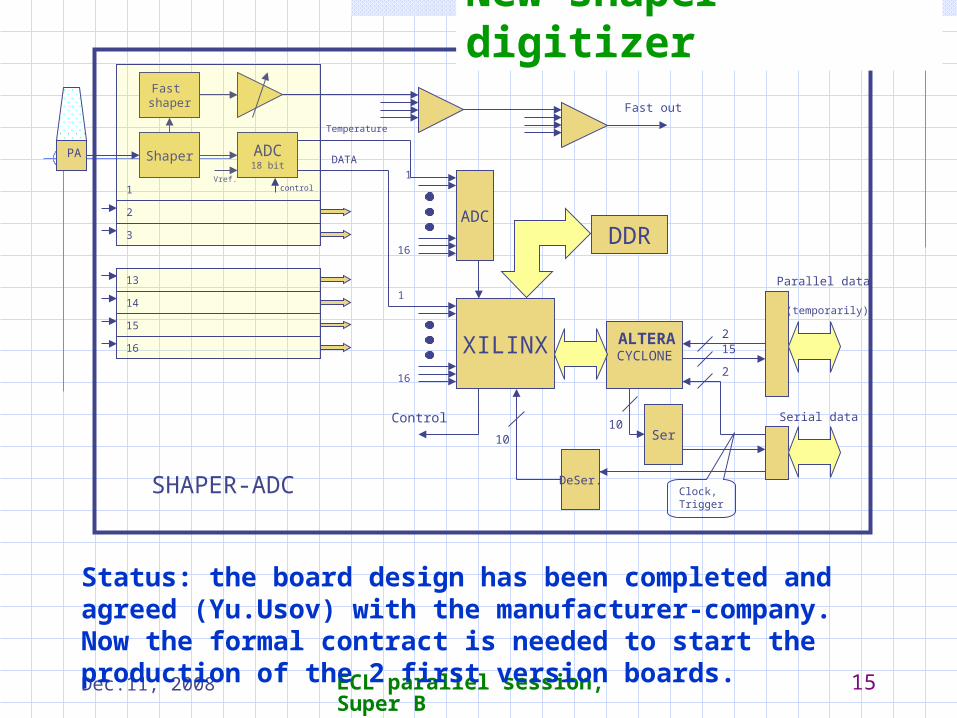
New shaper-digitizer
Status: the board design has been completed and agreed (Yu.Usov) with the manufacturer-company. Now the formal contract is needed to start the production of the 2 first version boards.
Dec.11, 2008 ECL parallel session, Super B 16
Back up slides
Dec.11, 2008 ECL parallel session, Super B 17
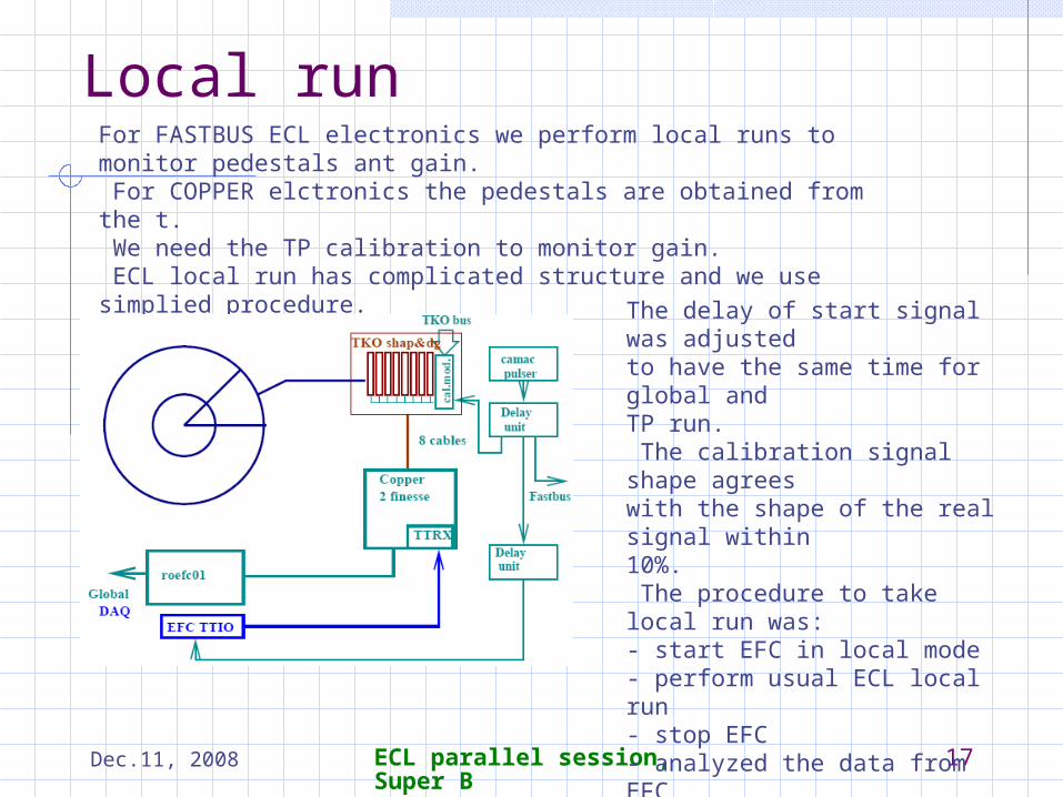
Local runFor FASTBUS ECL electronics we perform local runs to monitor pedestals ant gain. For COPPER elctronics the pedestals are obtained from the t. We need the TP calibration to monitor gain. ECL local run has complicated structure and we use simplied procedure.
The delay of start signal was adjustedto have the same time for global andTP run. The calibration signal shape agreeswith the shape of the real signal within10%. The procedure to take local run was:- start EFC in local mode- perform usual ECL local run- stop EFC- analyzed the data from EFC
Dec.11, 2008 ECL parallel session, Super B 18
Summer time - goals of the test
In the last summer shutdown 120 channels of the ECL BE were connected to the new shaper-digitizer boards. The goals of the test were:
Measurement of the noise and coherent noises
at detector Test of reliability of the readout at high rates Test of calibration procedure Long term test of the FPGA logic
Dec.11, 2008 ECL parallel session, Super B 19
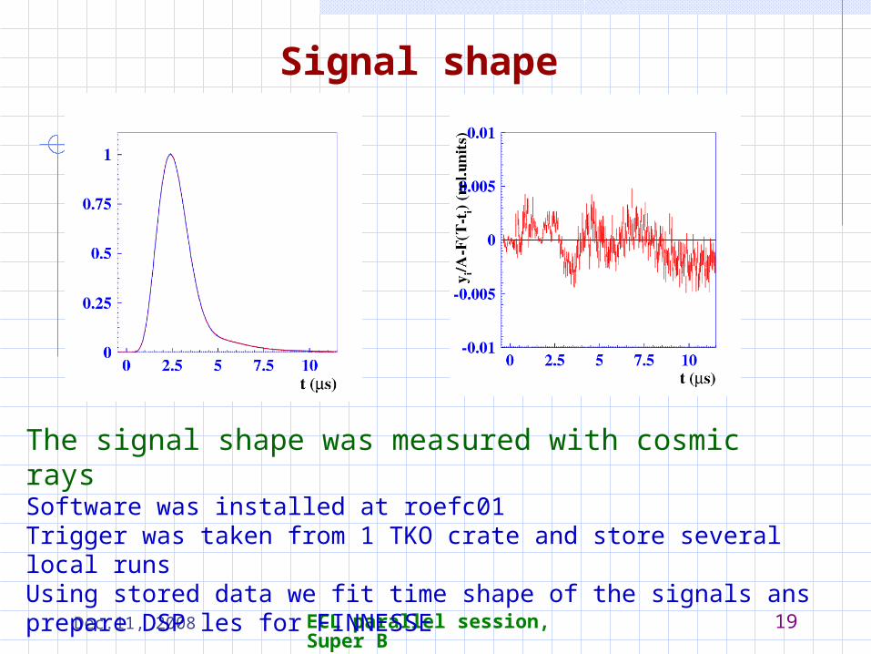
The signal shape was measured with cosmic rays Software was installed at roefc01Trigger was taken from 1 TKO crate and store several local runsUsing stored data we fit time shape of the signals ans prepare DSP les for FINNESSE
Signal shape
Dec.11, 2008 ECL parallel session, Super B 20
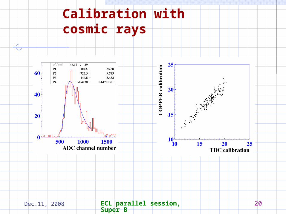
Calibration with cosmic rays

Dec.11, 2008 ECL parallel session, Super B 21
Consistency
We searched for possible events with some inconsistence in FASTBUS and COPPER data
Shaded area – new electronics

Dec.11, 2008 ECL parallel session, Super B 22
Electronics noise
Incoherent noises :5.7 channels(330keV) (outer layers)7.1 channels(410keV) (inner layers)10% higher than expected
Coherent noises :1.2 channels(70 keV) for 16 channels (1 module)0.6 channels(30keV) for 120 modulesOn test bench we got 1.0 channelCalibration module had given big noise and was modied to have possibility to dissconect by relay.
Dec.11, 2008 ECL parallel session, Super B 23
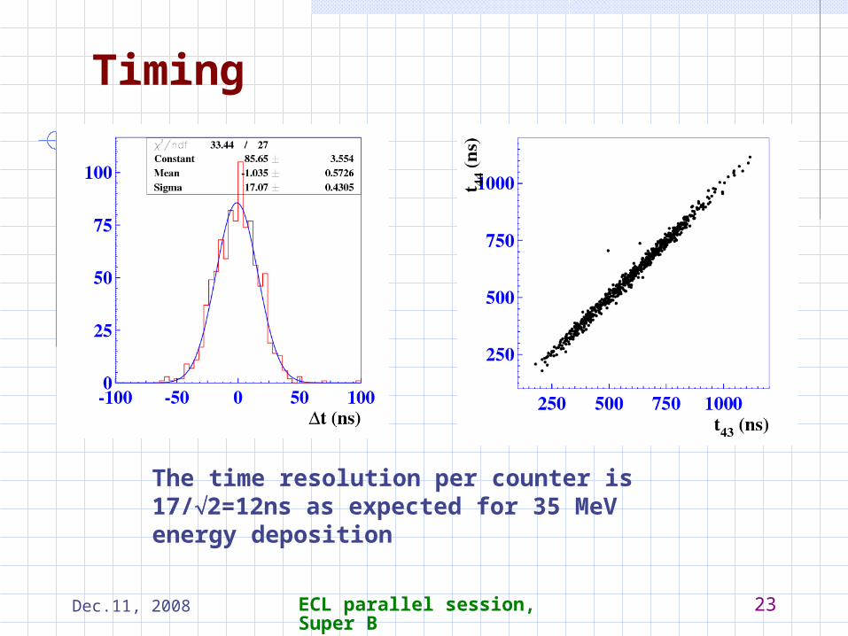
Timing
The time resolution per counter is 17/2=12ns as expected for 35 MeV energy deposition
Dec.11, 2008 ECL parallel session, Super B 24