Embed Size (px)
Citation preview
RESUME OF THE REPORTS OF THE TECHNICAL SUBJECTS
1. STANDARD OF THE QUESTION PAPER
The Chief Examiners reported that the standard of the paper was similar or comparedfavourably with those of the previous years and that the questions were within the scopeof the syllabus.
2. PERFORMANCE OF CANDIDATES
The Chief Examiners’ reports graded candidates’ performance from generally goodperformance to below average.
Subjects that recorded good performance were:Auto Mechanics 3, Building Construction 2 and Woodwork 2.Average performance was reported in Technical Drawing 2 & 3, Electronics 2,Woodwork 3, Metalwork 2 & 3, and ICT 2.
Subjects that recorded below average performance were: Building Construction 3, ICT 3,Auto Mechanic 2 and Electronics 3.
3. A SUMMARY OF CANDIDATES’ STRENGTHS
The following were identified as strengths of the candidates:
(1) ORDERLY PRESENTATION OF ANSWERSMajority of candidates offering Technical Drawing 2, ICT 2, and Auto Mechanics 3presented their work systematically and followed the demands of the rubrics.Most candidates for Metalwork 3 produced neat and clean filings.
(2) APPLICATION OF KNOWLEDGE AND SKILLSMajority of candidates of Metalwork 3, Auto Mechanic 3 and Technical Drawing 2demonstrated insightful knowledge and good skills in producing their artifacts andsketches.
(3) DEMONSTRATION OF PRACTICAL SKILLSMost of the candidates offering Woodwork 3, Metalwork 3, ICT 3, Auto Mechanic 3and Technical Drawing 3 exhibited the required skills to execute the tasks requestedby the questions.
4. A SUMMARY OF CANDIDATES’ WEAKNESSES
The Chief Examiners identified the following as weaknesses of the candidates:(1) Inadequate preparation for the examination

Majority of candidates for ICT 2, Auto Mechanic 2 and Building Construction 2 werereported to have not prepared adequately for the examination. Their responsesdemonstrated limited knowledge in the basics of their respective subjects.
(2) POOR PRACTICAL SKILLSA few candidates for Woodwork 3 were unable to read and interpret the workingdrawings correctly. Most candidates for ICT 3 were unable to create the databaserelationship and saved HTML files as “txt” files.
Most candidates for Metalwork 3 demonstrated they lacked effective control ofcutting tools, filing was excessively carried through and some candidates kept burrsand sharp edges on their finished work.
(3) POOR COMMUNICATION SKILLSMost candidates for Auto Mechanics 3 demonstrated their poor communication skillsthrough their oral responses to oral questions put to them. This was also evident incandidates written responses in Building Construction 2, Metalwork 2, ICT 2 andAuto Mechanic 2.
5. SUGGESTED REMEDIES
The following suggestions were enumerated by the Chief Examiners to help improveupon candidates’ weaknesses:(1) Teachers should endeavour to complete their syllabuses with candidates so that they
can answer questions from all areas of the syllabus.(2) Teachers should as much as possible match theory with practice to enable candidates
to grasp abstract concepts better.(3) Candidates should be encouraged to buy relevant or recommended text books and
reading materials on their subject and study them to broaden their knowledge on thesubject.
(4) Teachers should take candidates to industrial visits to link theory to practice.(5) Candidates should be provided with the necessary tools, equipment and materials to
enable them produce neat and accurate work.(6) Candidates should be encouraged to make time for reading story books to equip them
enough to communicate well orally and in writing.

APPLIED ELECTRICITY 2
1. GENERAL COMMENTS
The standard of this year’s paper has not changed much from the previous years.
There has been slight improvement in candidates’ performance in the direct current andalternating current section of the syllabus.
However, candidates’ performance in the electronics section of the syllabus is not verymuch encouraging as expected. Efforts must be made to allocate equal time to bothsections of the syllabus.
2. A SUMMARY OF CANDIDATES’ STRENGTHS
Candidates’ strengths were noted in the following areas:(i) Sketch and label of a BAR MAGNET and Electromagnet.(ii) Stating differences between bar magnet and electromagnet.(iii) Solving problems in RLC a.c series circuit and how to determine IMPEDANCE,
total current and phase angle.(iv) Application of semiconductor diodes; Advantages of transistors over valves.(v) Definition of a fuse and naming types of fuses.
3. A SUMMARY OF CANDIDATES’ WEAKNESSES
Weaknesses were noted on the following questions:(i) The difference between a shunt motor and a shunt generator. This ought to be
known before one could calculate to get correct answers for the terminal voltage,back e.m.f., armature resistance and armature current.
(ii) Labelling and drawing symbols for TRIAC and THYRISTOR.(iii) To calculate the voltage gain and output voltage from a given non-inverting
operational amplifier circuit.(iv) Advantages of FM over AM and the formula to use to calculate the wavelength of
a radio signal with a velocity given.
4. SUGGESTED REMEDIES
(i) Class and homework exercises must be given to students.(ii) The syllabus must be completed before examinations are taken.
5. DETAILED COMMENTS
Question 1
(a) Sketch and label the following:(i) a bar magnet;(ii) an electromagnet.
(b) State two differences each between a bar magnet and an electromagnet.
A very popular and well answered question by majority of the candidates. Manycandidates had no difficulty to draw the bar magnet. However, some candidates couldnot sketch an electromagnet properly.
The following points must be noted:
(a) The soft iron bar cannot operate as an electromagnet without coil or windingaround it.
(b) An electromagnet needs external source of supply to function while a bar magnetdoes not. Hence magnetism of an electromagnet is not permanent unlike that of abar magnet.
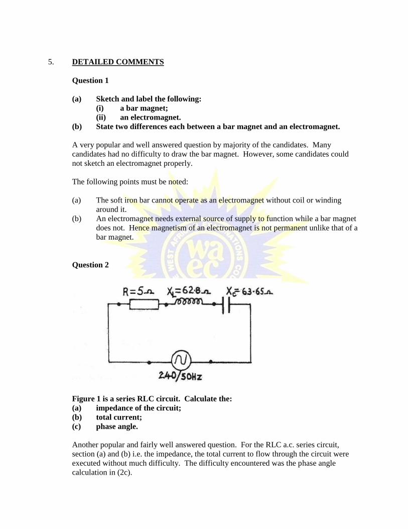
Question 2
Figure 1 is a series RLC circuit. Calculate the:(a) impedance of the circuit;(b) total current;(c) phase angle.
Another popular and fairly well answered question. For the RLC a.c. series circuit,section (a) and (b) i.e. the impedance, the total current to flow through the circuit wereexecuted without much difficulty. The difficulty encountered was the phase anglecalculation in (2c).

The sketch of the impedance triangle by some of the candidates should have helped agreat deal in calculating the phase angle.
From the impedance triangle the angle θ can be calculated using either
Cosθ Tanθ Sinθ
Z
R
R
XL
Z
XL
Question 3
(a) Define a fuse.(b) List two types of fuses.(c) State three reasons for earthing in an electrical installation.
(a) The protective device fuse was quite well defined. However, (b) and (c) whichasked for different types of fuses and reasons for earthing, exposed somecandidates for their lack of simple skill in electrical installation work.
The common type of fuses in electrical installation work are: rewirable fuse,cartridge fuse, high breaking capacity fuse.
Some reasons for earthing are the following: To prevent electric shock and fireoutbreak.
Question 4
A shunt motor has the following features:Back e.m.f. (Eb) = 220V;Field resistance (r.f.) = 150 ΩField current (If) = 1.5.A;Supply current (I) = 31.5A.

Calculate the:(a) terminal voltage;(b) armature resistance;(c) power output at the motor shaft.
Not popular and poorly answered question. Many candidates failed to arrive at thecorrect answers due to lack of understanding of the principle of operation of a d.c. shuntmotor.
The quantities required to calculate the values are as follows:
(a) Terminal voltage Vt = If x rf .Where If = field current and rf = field resistance
(b) Armature resistancea
bta I
EVr
Ea = back emfIa= armature current
(c) Power output of the motor (mechanical) Po = Eb x Ia
Question 5
(a) State three(i) applications of a semiconductor diode;(ii) advantages of transistors over valves.
(b) Draw a labelled circuit symbol of the following:(a) a triac;(b) athyristor.
Section (a) The application of semiconductor diodes and advantages of transistorsover thermionic valves did not pose much problem to the candidates.
However, the drawing and labelling of circuit symbols for the following devices werepoorly carried out:(i) a triac;(ii) athyristor.
Question 6
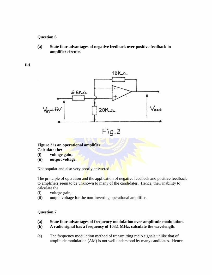
(a) State four advantages of negative feedback over positive feedback inamplifier circuits.
(b)
Figure 2 is an operational amplifier.Calculate the:(i) voltage gain;(ii) output voltage.
Not popular and also very poorly answered.
The principle of operation and the application of negative feedback and positive feedbackto amplifiers seem to be unknown to many of the candidates. Hence, their inability tocalculate the(i) voltage gain;(ii) output voltage for the non-inverting operational amplifier.
Question 7
(a) State four advantages of frequency modulation over amplitude modulation.(b) A radio signal has a frequency of 103.1 MHz, calculate the wavelength.
(a) The frequency modulation method of transmitting radio signals unlike that ofamplitude modulation (AM) is not well understood by many candidates. Hence,
their failure to mention some advantages of frequency modulation over that ofAM.
(b) Some candidates managed to calculate the wavelength correctly assuming thevelocity of light not given in the question as 3 x 10⁸ m/s with the radio signalfrequency of 103.1 MHz.

APPLIED ELECTRICITY 3
1. GENERAL COMMENTS
The paper was well set. The two questions had no ambiguous or incorrect meanings.The questions were within the syllabus and the standard was very good. Candidates’performance has every year been improving and the very few whose performances areweak show that the candidates do not attend classes and therefore could not use theapparatus and hence had wrong instrument readings.
2. A SUMMARY OF CANDIDATES’ STRENGTHS
(i) Most candidates are now interested in the practical exercises and are able to docorrect connections of the circuits.
(ii) A number of the candidates are able to use their digital multimeters.(iii) Candidates who performed very well were able to link the theory lesson to the
practicals and as a result were able to answer neatly all that was required in eachexperiment.
3. A SUMMARY OF CANDIDATES’ WEAKNESSES
(i) Candidates did not know that question 2 was a curve and therefore could notrespond to the question.
(ii) A number of candidates mixed up the instrument readings, i.e. the instrumentranges selected were not considered as milliamperes or amperes.
(iii) Whatever displacement that appeared on their digital meters were just recorded,e.g. 0.009A on Ampere range was taken 9A as compared with 9mA range.
4. SUGGESTED REMEDIES
(1) More experiments should be carried out with the teachers.(2) Regular use of the digital/analog meters. Conversion of milliammeter reading to
ammeter reading should be taught.
5. DETAILED COMMENTS
Candidates were provided with the following apparatus:onevariac transformer (0 – 20 V) a.c.;one ammeter (0 – 1A) a.c;one voltmeter (0 – 15 V) a.c;four 10 Ω, 5 W resistors;one 20 Ω, 5 W resistors;1.5 mm2PVC cables;a set of hand tools.

Question 1
AIM: To verify the relationship between current and voltage at constant resistance.
(a) Connect the circuit as shown in Figure 1.(b) Ask the supervisor to check the circuit connection.(c) Copy Table 1 into your answer booklet.
Voltage (V) Current (A) Resistance (R) = V/I02468
10
(d) Switch on the variac.(e) Set the variac to 0 V.(f) Read and record the ammeter readings in Table 1.(g) Increase the variac voltage in steps of 2 V to 10 V and record the
corresponding ammeter reading in Table 1.(h) Switch off the variac.(i) Complete Table 1.(j) Plot a graph of voltage (V) on the vertical axis against current (A) on the
horizontal axis.(k) Determine the slope of the graph.(l) Comment on the graph.
Majority of the candidates performed the connections correctly.

In this practical paper, it has been observed that candidates always have problem withquestions that come with graph work.
This goes to show that candidates need to work very hard on graph work.
Performance of candidates was generally average.
Question 2
AIM: To verify the relationship between current and resistance at constant voltage.
(a) Connect the circuit as shown in Figure 2.(b) Ask the supervisor to check the circuit connection.(c) Copy Table 2 into your answer booklet.
Resistance (Ω) Current (A) Voltage (V) = IR10203040
(d) Switch on the variac and set it to 10 V.(e) Read and record the ammeter readings in Table 2.(f) Switch off the variac(g) Repeat steps (d) to (f) for each corresponding series connected total
resistance value shown in Table 2.(h) Complete Table 2.(i) Plot a graph of current (A) on the vertical axis against resistance (Ω) on the
horizontal axis.(j) Comment on the graph.

Majority of the candidates performed the experiments correctly and therefore had goodreadings.
Instead of a variac to perform the experiment most schools used transformers.
Candidates’ performance was fair.
AUTO MECHANICS 2
1. GENERAL COMMENTS
Candidates’ performance has drastically plummeted even though the standard of papercompared with those of previous years has been the same.
2. A SUMMARY OF CANDIDATES’ STRENGTHS
Only one or two candidates showed some excellence in some of the answers provided tosome of the question.
For example in Question 2 which required candidates to explain the term ‘Valve Timing’a candidate stated that ‘Valve timing is an orderly way of setting the valves to open andclose at the right time’.
On explaining what ‘Valve Overlap’ means another candidates stated ‘Valve overlap’ isthe period where both exhaust and inlet valve per cylinder open to allow the momentumof the escaping exhaust gas to draw fresh charge into the cylinder.
Again, another candidate in answering Question 4(b), stated that the coil serves a step uptransformer by increasing the voltage needed to ignite the compressed fuel and airmixture.
These answers were commendable and encouraging.
3. A SUMMARY OF CANDIDATES’ WEAKNESSES
Weaknesses identified were as follows:
(1) Gross lack of knowledge in the subject.(2) Poor communication (written); language very hazy.(3) Poor sketches and diagrams which were not workable.
4. SUGGESTED REMEDIES
(1) It is important that both teachers and candidates get serious with the subject. Thebest methodology for teaching the subject is to match theory with practice. Thisenables candidates/students to grasp abstract concepts better.
(2) Candidates should be encouraged to buy some relevant or recommendedtextbooks on the subject and study.

(3) Industrial visits cannot be over emphasized if school workshops are not properlyequipped.
5. DETAILED COMMENTS
Question 1
(a)(i) A good number of candidates could not answer the question properly.Answers expected for (a)(i) included:- It resists sideways slipping- It ensures even wear- It ensures quiet running- It does not wear rapidly
(a)(ii) Answers expected for (a)(ii) which are demerits of pattern X were- It is not very good on fore and after grip.- It has poor road grip or traction
(a)(iii) Candidates were to give two characteristics of pattern Y. Answersexpected include the following:- It has good wear resistance or lasts longer- It has good steering characteristics or it has good road grip/tractionor good braking effect.- It is used on trailers and farm implement.
(b) (i) A good number of candidates listed tube and tubeless tyres whichwas wrong. The two types of tyre construction are:(1) Radial Ply and(2) Cross Ply tyre constructions.
(ii) This part required candidates to explain the difference between the twotypes of tyre construction listed in (b)(i). Candidates displayed gross lackof knowledge.
The difference between cross ply and radial ply tyres is that, in the crossply there are alternate plies which are arranged so that their cords cross,i.e. about 40º to the circumference, while in the radial ply, the cords of theplies do not cross but are arranged radially, i.e. at 90º to the tangents of thewheel.
(c) The candidates were to list two types of wheel. Candidates’ performance wasvery bad. Answers expected include:- pressed steel- disc or ventilated disc- wire wheel or spoke wheel- alloy wheel
Question 2
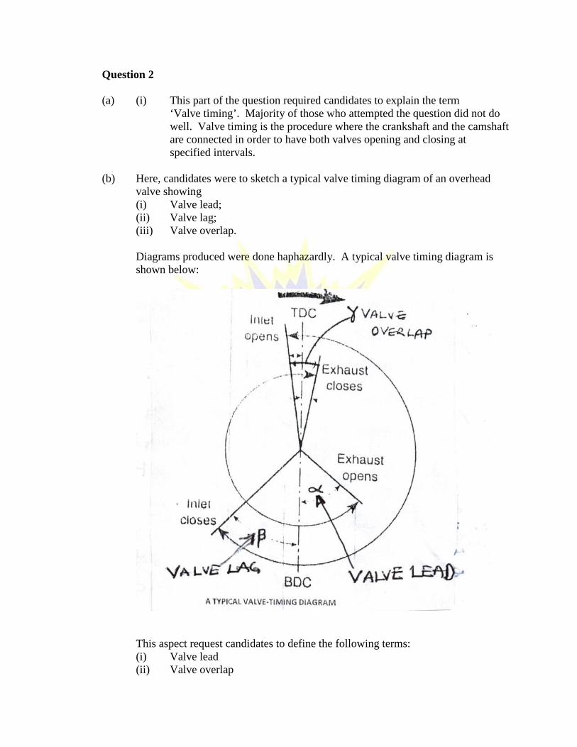
(a) (i) This part of the question required candidates to explain the term‘Valve timing’. Majority of those who attempted the question did not dowell. Valve timing is the procedure where the crankshaft and the camshaftare connected in order to have both valves opening and closing atspecified intervals.
(b) Here, candidates were to sketch a typical valve timing diagram of an overheadvalve showing(i) Valve lead;(ii) Valve lag;(iii) Valve overlap.
Diagrams produced were done haphazardly. A typical valve timing diagram isshown below:
This aspect request candidates to define the following terms:(i) Valve lead(ii) Valve overlap
The majority of definitions were nothing to write home about. What is required isas follows:(i) Valve lead is the early opening of the inlet valve before the piston
reaching the top dead centre or early opening of the exhaust valve beforethe piston reaches the bottom dead centre (BDC).
(ii) Valve overlap is the period when both inlet and exhaust valves remainopened at the same time OR opening of the inlet valve when the exhaust isabout to close
Question 3
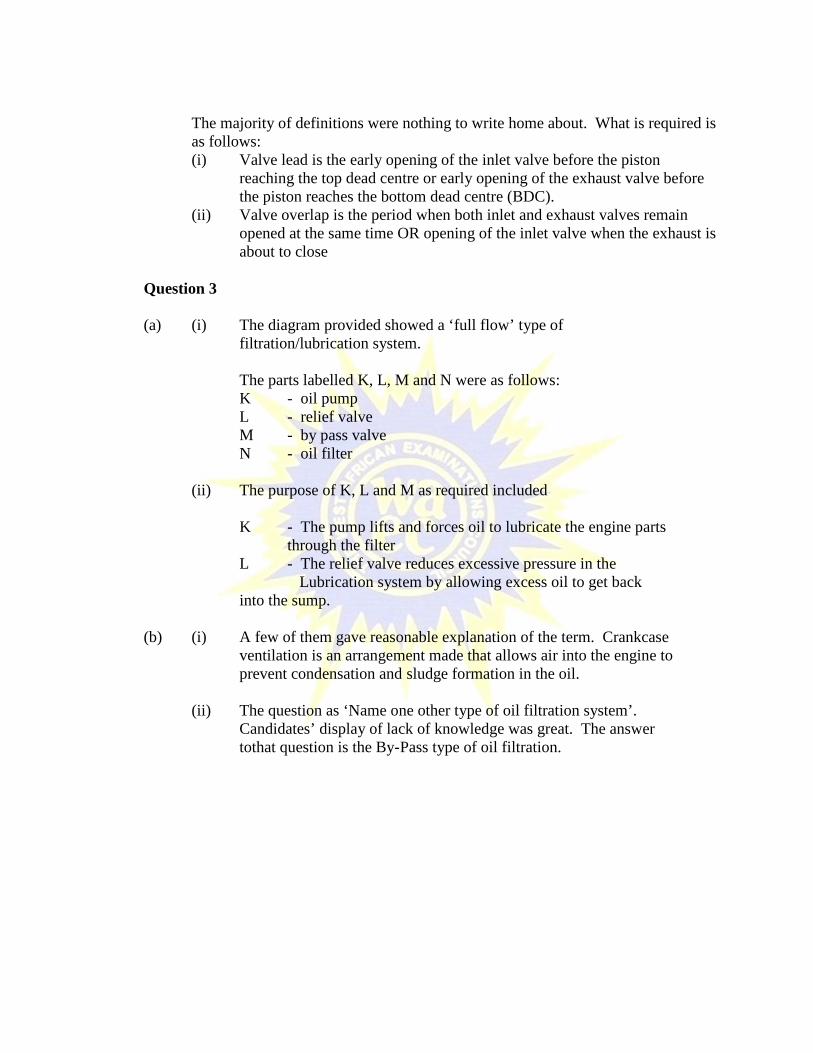
(a) (i) The diagram provided showed a ‘full flow’ type offiltration/lubrication system.
The parts labelled K, L, M and N were as follows:K - oil pumpL - relief valveM - by pass valveN - oil filter
(ii) The purpose of K, L and M as required included
K - The pump lifts and forces oil to lubricate the engine partsthrough the filter
L - The relief valve reduces excessive pressure in theLubrication system by allowing excess oil to get back
into the sump.
(b) (i) A few of them gave reasonable explanation of the term. Crankcaseventilation is an arrangement made that allows air into the engine toprevent condensation and sludge formation in the oil.
(ii) The question as ‘Name one other type of oil filtration system’.Candidates’ display of lack of knowledge was great. The answertothat question is the By-Pass type of oil filtration.
Question 4
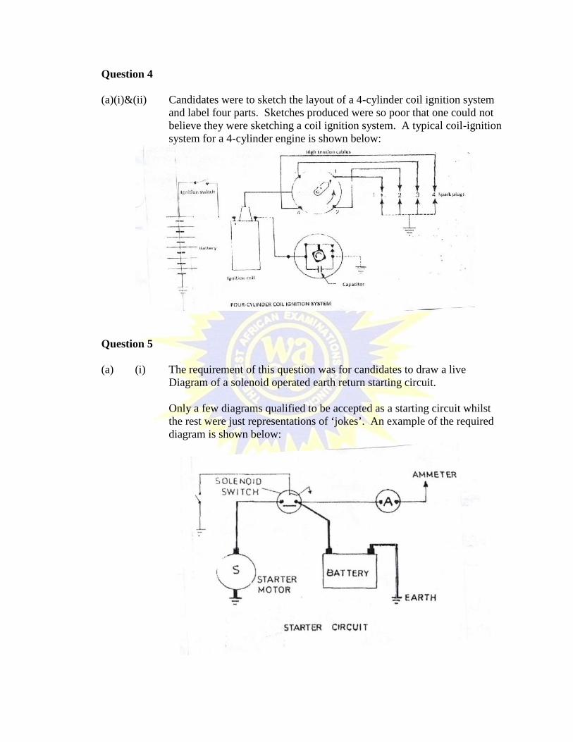
(a)(i)&(ii) Candidates were to sketch the layout of a 4-cylinder coil ignition systemand label four parts. Sketches produced were so poor that one could notbelieve they were sketching a coil ignition system. A typical coil-ignitionsystem for a 4-cylinder engine is shown below:
Question 5
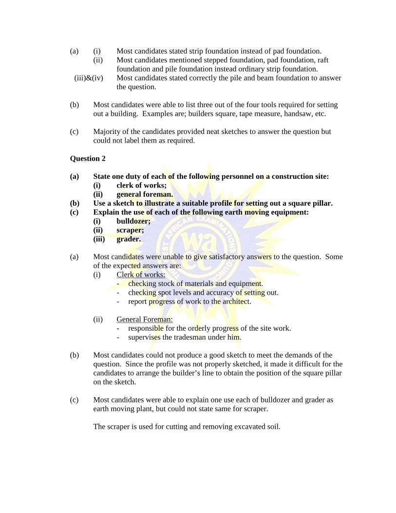
(a) (i) The requirement of this question was for candidates to draw a liveDiagram of a solenoid operated earth return starting circuit.
Only a few diagrams qualified to be accepted as a starting circuit whilstthe rest were just representations of ‘jokes’. An example of the requireddiagram is shown below:

(b) Candidates were to label the following parts on the circuit as shown:- battery- starter switch- solenoid switch and- starter motor
(c) Again, candidates were to name two parts of an alternator. A few could name thetwo parts correctly. Parts of the alternator included:- stator- rotor- slip ring- brushes- field winding- shaft- pole pieces- drive end- drive bracket- bushes- heat sink- rectifier/diode- regulator- capacitor

AUTO MECHANICS 3
1. GENERAL COMMENTS
The standard of the paper is comparable to that of previous years.
The performance of candidates indicated a little improvement over that of the pastyear.
2. A SUMMARY OF CANDIDATES’ STRENGTHS
(1) Candidates selected tools and equipment correctly and took the necessary safetyprecautions in handling them.
(2) Candidates performed the tasks with confidence.(3) The candidates followed the necessary procedures demanded by the questions.
3. A SUMMARY OF CANDIDATES’ WEAKNESSES
(1) Some candidates used wrong tools for the jobs.(2) Candidates’ inability to identify the location of some components of the engine.(3) Inadequate knowledge of candidates in the subject matter rendered candidates
unable to carry out some tasks.(4) Candidates’ inability to assemble some of the parts they dismantled.(5) Inability to communicate effectively.
4. SUGGESTED REMEDIES
(1) Schools should be encouraged to engage practical oriented teachers to traincandidates.
(2) Students should be encouraged to read books to improve upon their grammar andcommunication skills.
(3) Students should be encouraged to visit local vehicle mechanics to learn andunderstand the trade.
(4) Names of component parts of engines should be taught during theoretical andpractical lessons.
5. DETAILED COMMENTS
The Auto Mechanics 3 (Practical) paper comprise two questions:Question 1 – Diesel Fuel InjectorQuestion 2 – Cylinder Head Assembly

QUESTION 1 - DIESEL FUEL INJECTOR
(a) Candidates were able to identify and remove the injector following the necessaryprocedures, e.g. removal of pressure, leak off pipes and securing bolts of injector.
(b) Candidates were able to fix the injector to the test rig facing downwards andoperated the lever. Some were not able to read pressure correctly.
(c) Candidates removed the injector from test rig, fit it in the vice, dismantled andcleaned parts.
(d) Candidates clamped the injector in the vice but some were guided beforeassemblying it.
(e) Candidates mounted the injector to the test rig, primed the lever increased orreduced spring tension with shims to correct spray pattern. Some could not readthe pressure on the gauge and were guided by the examiner.
(f) Candidates removed injector and finally frightened with securing bolt and pipesconnected.
(g) Some two relevant questions asked were(1) State one cause of a diesel engine emitting black smoke.(2) Why is it necessary to maintain a standing pressure between the line of the
fuel injection pump and the injector?(h) With selection and handling of tools and equipment some student used wrong
ones for the wrong job. The setup was not proper. Most of the tools andequipment were obsolete, this resulted in candidates not able to use themconfidently.
QUESTION 2
(a) Candidates found it difficult to identify valve, but when guided as cylinder headcover were able to remove nuts and bolt to take it off.
(b) Candidates were able to remove retaining bolts and remove rocker shaft assembly.(c) Candidates were able to remove securing circlip and pull out rocker arm.(d) Candidates inspected the rocker arm, sleeve face for wear and crack. Some could
not determine the degree of wear.(e) Candidates pushed in the spring, pushed the rocker arm, place washer and
securing pin.(f) Candidates mounted the shaft assembly in positon, guided the securing bolts,
aligned the rocker arm to their respective valves and finally tightened the bolts,but some had to be guided to finally tighten bolts sequentially.
(g) Candidates replaced gasket, valve cover, guided bolts and finally tightened themsequentially.
(h) Some two relevant questions asked were(1) Why is it important to tighten bolts sequentially?(2) Why is the inlet valve sometimes larger than the exhaust valve?
(i) Candidates observed safety regulations as regards neatness, handling ofcomponents, tools and equipment.

BUILDING CONSTRUCTION 2
1. GENERAL COMMENTS
The standard of the paper satisfied the needs and demands of the syllabus and comparedfavourably with that of the previous years. It tested all the domains required in shapingthe knowledge and skills of the candidates.
2. A SUMMARY OF CANDIDATES’ STRENGTHS
(1) Most candidates produced good sketches and legible handwritings.(2) Majority of candidates numbered their questions neatly.
3. A SUMMARY OF CANDIDATES’ WEAKNESSES
(1) Most candidates could not read and understand the questions very well.(2) Most candidates could not express themselves very well in the English Language
to answer questions.(3) Most candidates could not label their sketches very well.
4. SUGGESTED REMEDIES
(1) Teachers should prepare candidates very well by completing their syllabus withstudents.
(2) Candidates should make time for reading textbooks and story books to equipthemselves enough to communicate very well orally and in writing.
(3) Teachers should stress on the importance of labelling and teach candidates theproper methods of labelling.
5. DETAILED COMMENTS
Question 1
(a) Specify one type of foundation suitable for each of the following:(i) reinforced concrete framed building;(ii) sandcreteblockwall on a moderately firm ground;(iii) brickwall domestic building on a made-up ground;(iv) a two storey building on a deep marshy clay soil.
(b) List four tools used in setting out a building.(c) Sketch a cross section through a substructural wall and label the following
parts:(i) concrete strip of foundation;(ii) sandcreteblockwall;(iii) hardcore filling;(iv) damproof course.
(a) (i) Most candidates stated strip foundation instead of pad foundation.(ii) Most candidates mentioned stepped foundation, pad foundation, raft
foundation and pile foundation instead ordinary strip foundation.(iii)&(iv) Most candidates stated correctly the pile and beam foundation to answer
the question.
(b) Most candidates were able to list three out of the four tools required for settingout a building. Examples are; builders square, tape measure, handsaw, etc.
(c) Majority of the candidates provided neat sketches to answer the question butcould not label them as required.
Question 2
(a) State one duty of each of the following personnel on a construction site:(i) clerk of works;(ii) general foreman.
(b) Use a sketch to illustrate a suitable profile for setting out a square pillar.(c) Explain the use of each of the following earth moving equipment:
(i) bulldozer;(ii) scraper;(iii) grader.
(a) Most candidates were unable to give satisfactory answers to the question. Someof the expected answers are:(i) Clerk of works:
- checking stock of materials and equipment.- checking spot levels and accuracy of setting out.- report progress of work to the architect.
(ii) General Foreman:- responsible for the orderly progress of the site work.- supervises the tradesman under him.
(b) Most candidates could not produce a good sketch to meet the demands of thequestion. Since the profile was not properly sketched, it made it difficult for thecandidates to arrange the builder’s line to obtain the position of the square pillaron the sketch.
(c) Most candidates were able to explain one use each of bulldozer and grader asearth moving plant, but could not state same for scraper.
The scraper is used for cutting and removing excavated soil.

Question 3
(a) State six stages involved in fixing tongue and groove timber flooring to ahardened concrete floor slab using embedded battens.
(b) Name one suitable material for the manufacture of each of the followingfittings:(i) shower rose;(ii) wash basin;(iii) bath tub.
(a) Most candidates did not attempt this question and the few that attempted it couldnot answer it well. The stages involved include:- treating the exposed battens and timber boards with the required
preservations.- measuring and cutting the timber boards to the required sizes.- laying bituminous felt or bitumen on the concrete slab.
(b) Most candidates could not give satisfactory responses.
The required answers include:- shower rose: - stainless steel, plastic- wash basin: - ceramics, plastic, porcelain.- bath tub: - ceramics, plastic, stainless steel..
Question 4
(a) State five functions of plaster in a building.(b) Sketch a pictorial view of each of the following:
(i) Quartering gauge;(ii) Gauge box.
(c) List two materials used in the manufacture of cement.
(a) Majority of candidates were able to state the five functions of plaster on building.The few that would not state all at least stated three of them.
(b) The sketch of the quatering gauge was a bother to most candidates. Majority ofthem were however able to sketch the gauge box very well.
(c) Majority of candidates who attempted this question were able to answer thisquestion very well.

Question 5
(a) State the function of each of the following parts as used in door construction:(i) transome;(ii) muntin;(iii) hardwood threshold.
(b) State two functions of a roof covering.(c) Sketch a timber stair of two steps and label the following parts:
(i) nosing;(ii) going;(iii) tread.
(a) Most candidates could not answer this question satisfactorily.- Transome: provides horizontal separation between the door and thefan-light.- Muntin: creates spaces vertical for the panels.- Hardwood threshold: throws off rainwater at the floor level blown bystorm.
(b) Candidates were able to answer this question very well.
(c) Most candidates stated fairly good answers to satisfy the demands of the question.

BUILDING CONSTRUCTION 3
1. GENERAL COMMENTS
The standard of the paper compared favourably with that of the previous year.Candidates’ performance was average being slightly better than that of the previous year.
2. A SUMMARY OF CANDIDATES’ STRENGTHS
Candidates showed remarkable improvement in:(i) numbering their work neatly.(ii) spacing out their work for clarity.(iii) sketching proportionally and with much clarity.
3. A SUMMARY OF CANDIDATES’ WEAKNESSES
(1) Candidates could not use technical terms or jargons effectively to answerquestions and where they attempted, they were wrongly used.
(2) Candidates demonstrated their weakness in the practical aspects of the subject byshying away from practical oriented questions.
4. SUGGESTED REMEDIES
(1) Teachers should introduce and encourage candidates to use technical terms andjargons in their expressions and responses.
(2) Students offering Building Construction should be given sometime on thetimetable to visit building sites to observe and familiarize themselves with theday-to-day activities on sites.
(3) Teachers should try as much as possible to link theory to practise to help studentsto understand what they are taught very well.
5. DETAILED COMMENTS
Question 1
(a) Fig. 1 shows the front view of a domestic building with sandcreteblockwallson a strip foundation. The external and internal wall surfaces of the buildingare finished with cement sand mortar. Use it to answer the followingquestions:

(i) Identify the elements labelled A, B and C.(ii) State one function of each of the elements labelled B and C.
(b) The floor of the building is finished with terrazzo tiles. Sketch a cross-sectionthrough the external wall from foundation to the finished floor level andlabel the following parts:(i) terrazzo tiles;(ii) ground floor slab;(iii) finished ground level;(iv) foundation concrete.
(c) (i) Sketch to show how the door frame is fixed to the blockwall as thewalling processes.
(ii) State six stages involved in hanging the wooden door to the existingframe in (c)(i).
(d) (i) List in sequence, eight operations involved in applying a three-coatrender to the external surface of the wall using a ready mix mortar.
(ii) State four reasons for rendering the external surface of the wall.
(a) Almost all candidates attempted as a compulsory question with good answers. Afew however indicated element B as glass/glazed window instead of fanlight.Candidates’ responses were good.
(b) Candidates sketches and labelling of the parts were generally good. A fewhowever were confused about the position of earth filling and finished groundlevel.

(c) (i) Most candidates sketched the wood frame and wall without the fixinglugs, wood block, pads or nails.
(ii) Most candidates lacked the technique knowledge needed to answer thisquestion. The required answers include:(1) compare the dimensions of the door to those of the frame;(2) reduce the size of the door to fit the frame;(3) mark the positions of the hinges on the door and frame;(4) screw the hinges to the door.
(d) Majority of the candidates could not answer the first part well. The sequencingwas poorly expressed, mortar dabs to gauge thickness of the first coat as atechnical element were not mentioned.
The second part of this question was equally poorly attended to. The requiredanswers were:(1) to check rainwater penetration through the wall;(2) to provide a uniform and fair surface;(3) to allow for ease of painting and application of other finishes.
Question 2
(a) State ten stages involved in transferring the markings on a profile board fora strip foundation to the ground for the trench excavation works.
(b) State three reasons for levelling and ramming the bottom of a trenchexcavation to receive the foundation concrete.
(c) Describe a method of preventing rising subsoil moisture from getting to thetop surface of a ground floor slab.
`(a) Very few candidates attempted this question. The stages were no clearly stated.
It was quite a difficult question to the candidates. Among the required answersare:(1) check the accuracy of the setting out and marking out of the trench lines
on the profile boards;(2) stretch the ranging lines on the points marked on the profile boards.
(b) No candidate answered this question correctly. Among the reasons for levellingand ramming bottom of trench excavation are:(1) provided a level base for the foundation concrete;(2) provided a firm base for the strip foundation;(3) eliminated void spaces beneath the foundation concrete.
(c) Most candidates stated the use of DPM to prevent the rise of moisture but couldnot explain it very well. Among the methods is the use of thick dense concretewith or without Damp Proof Membrane (DPM) over the foundation walls.
Question 3
(a) (i) State three chemicals used in preserving timber.(ii) Describe two methods of applying a preservative to a sawn timber.
(b) Sketch a longitudinal section through a concrete staircase and label thefollowing parts:(i) landing;(ii) tread;(iii) riser;(iv) flight.
(d) Explain the purpose of a rag bolt in roof construction.
(a) (i) Candidates could not list three chemicals used in preserving timberThe required answers are:(1) creosote;(2) solignum;(3) bromide solution;(4) phenolformaladehyde.
(ii) Candidates could not provide any good descriptions. Majority deviatedand rather described methods used in the seasoning of timber. Therequired answers include:(1) pressure impregnation: Wood put in a pressure tank and chemical
forced into the pores of the timber.(2) immersing the wood in chemical for the pore to absorb chemical.
(b) A very popular question among the candidates. Majority of the sketches weregood and well labelled.
(c) Most candidates gave very good explanations to answer this question.
Question 4
(a) Explain the difference between a raft foundation and a wide strip foundation.(b) Explain the following terms in relation to concrete works:
(i) batching;(ii) placing;(iii) curing.
(c) Use a sketch to illustrate how a metal shield is used to prevent termites fromentering a building and label the following parts:
(i) finished ground level;(ii) strip foundation;(iii) metal shield;(iv) external wall.
(a) Candidates’ responses were very poor. The required answers include:The raft foundation covers the entire ground floor plan area of the building whilethe width of the wide strip foundation is wider than three times the thickness ofthe wall it supports.
(b) Candidates answered this question poorly. Candidates lacked the theory andactual technical terms to answer the question.(i) Batching: Is measuring concrete materials either by volume or weight.(ii) Placing: A process of putting the mixed concrete it its final position before
stiffening occurs.(iii) Curing: A method of keeping a newly laid concrete moist until it gains
sufficient strength.
(c) Majority of candidates were able to sketch a section through a floor but could notlocate the exact position where the metal shield should be placed. The metalshield is placed in the external wall beneath the oversite concrete.
Question 5
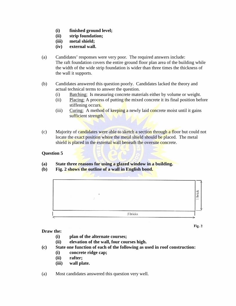
(a) State three reasons for using a glazed window in a building.(b) Fig. 2 shows the outline of a wall in English bond.
Draw the:(i) plan of the alternate courses;(ii) elevation of the wall, four courses high.
(c) State one function of each of the following as used in roof construction:(i) concrete ridge cap;(ii) rafter;(iii) wall plate.
(a) Most candidates answered this question very well.

(b) This question was poorly answered by candidates. Majority of candidates couldnot sketch the plan of the alternate courses of an English bond nor the elevation ofthe wall.
(c) Majority of candidates provided accurate responses to answer this question. Afew however could not state the position and function of the rafter satisfactorily.The rafter spans from the eaves to the ridge in a pitch roof in order to support thepurlins.
Question 6
(a) State three reasons for shoring the walls of a building.(b) Sketch an independent metal scaffold and label the following parts:
(i) standard;(ii) guard rail;(iii) toe board;(iv) sole plate;(v) external wall;(vi) platform.
(c) State three factors that influence the choice of a roof type of a domesticbuilding.
(a) Most candidates produced poor responses. The required answers include:(1) to repair a defective lower part of the wall;(2) to rebuild or deepen the existing foundation;(3) to allow for making an opening in an existing wall.
(b) Majority of candidates produced good sketches and labelling to answer thisquestion.
(c) Most candidates’ responses were not satisfactory. The required responsesinclude:(1) climatic conditions of the area;(2) span of the building or walls to be roofed;(3) availability of materials for its construction.

ELECTRONICS 2
1. GENERAL COMMENTS
The standard of the paper was good and compared favourably with that of the previousyears.
The overall performance compared with that of the previous years is generally poor.
2. A SUMMARY OF CANDIDATES’ STRENGTHS
(1) Some of the candidates had indepth knowledge of capacitive circuit.(2) Some of the candidates also had knowledge about sources of power supply.
3. A SUMMARY OF CANDIDATES’ WEAKNESSES
(1) Majority of the candidates did not demonstrate knowledge and understandingof electronics.
(2) Most of the candidates did not answer their questions satisfactorily.(3) Most of the candidates did not understand the questions properly.(4) Most of the candidates did not prepare adequately for the examination.
4. SUGGESTED REMEDIES
(1) Candidates should prepare adequately towards future examination.(2) Candidates should be taught the techniques of answering questions.(3) Candidates should read widely on Electronics textbooks and periodicals to
broaden their knowledge in the subject.(4) Some recommended textbooks on Electronics should be made available to
students.
5. DETAILED COMMENTS
Question 1
(a) Define the term voltage regulation.(b) List five sources of power supply.(c) State three advantages of full-wave bridge rectifier over centre-tapped
rectifier.
(a) Candidates’ response to the question was very poor. Candidates could not definevoltage regulation correctly. Voltage regulation is defined as a measure of thedegree to which a power supply source maintains its output voltage stability undervarying load conditions orA change in the supply’s terminal voltage from no-loadto full load.

(b) Candidates’ response to the question were fair. The appropriate responses are:- a.c generators- d.c. generators- solar cells- power packs- accumulators- hydro- nuclear- wind
(c) Majority of the candidates could not respond to this question. The appropriateresponses are:(i) The need for a centre-tapped transformer is eliminated.(ii) It is less expensive.(iii) The PIV rating of the diode is one-half times that of the centre-tapped
circuit for the same d.c supply.(iv) It is smaller in size.(v) Output is doubled.
Candidates’ performance was fair.
Question 2
Figure 1, is a capacitive circuit.
Use the information given in Figure 1 to calculate the:(a) total equivalent capacitance of the circuit;(b) voltage across the 20 µF capacitor.

(a& b) Performance of candidates was average. The appropriate responses are asfollows:Equivalent capacitance of the cct:
(a) Capacitance of parallel capacitors= C1 + C2 + C3
= 6 + 8 + 16= 30 µF
=20
1
30
1
=60
5
60
32
= 12µF
(b) Q = cV= 12µF x 30 V= 360 µ C
V20 =C
Q
=20
360
= 18 V
Question 3
(a) Draw and label a positive clipping circuit diagram.(b) Describe the principle of operation in (a).
(a) Majority of candidates could not respond to the question. The appropriateresponses are:

(b) For positive half cycle of input, diode is forward biased and short circuited. Henceoutput is zero. For the negative half cycle of input, diode is reversed biased andopen circuited.
Question 4
(a) State Faraday’s law of electromagnetic induction.(b) With the aid of a labelled diagram, describe the principle of operation of an
electric bell.
(a) Candidates’ response to this question was poor. Few candidates were able to stateFaraday’s law of electromagnetic induction correctly. The appropriate responseis: Whenever there is relative motion between magnetic flux and coil, an e.m.f. isinduced. The rate of change of flux linkage is directly proportional to themagnitude of e.m.f. induced.
(b) Majority of candidates could not draw, label and describe the principle ofoperation of an electric bell.
The appropriate responses are:
LABELLED DIAGRAM OF AN ELECTRIC BELL
PRINCIPLE OF OPERATION OF AN ELECTRIC BELL
When the switch is pushed or closed, the circuit is completed and current flowsthrough the electromagnetic coil. As a consequence, the iron striker is attracted tothe electromagnet and strikes the bell. As the striker moves towards the bell, thecontact is broken so that current stops flowing through the coil whichconsequently loses its magnetism. The compressed spring is released and returnsthe striker to its original position which makes a new contact and so electricityflows again. This cycle is repeated for as long as the switch is closed.
Question 5
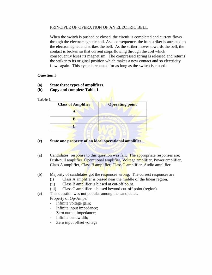
(a) State three types of amplifiers.(b) Copy and complete Table 1.
Table 1Class of Amplifier Operating point
A
B
C
(c) State one property of an ideal operational amplifier.
(a) Candidates’ response to this question was fair. The appropriate responses are:Push-pull amplifier, Operational amplifier, Voltage amplifier, Power amplifier,Class A amplifier, Class B amplifier, Class C amplifier, Audio amplifier.
(b) Majority of candidates got the responses wrong. The correct responses are:(i) Class A amplifier is biased near the middle of the linear region.(ii) Class B amplifier is biased at cut-off point.(iii) Class C amplifier is biased beyond cut-off point (region).
(c) This question was not popular among the candidates.Property of Op-Amps:- Infinite voltage gain;- Infinite input impedance;- Zero output impedance;- Infinite bandwidth;- Zero input offset voltage

Question 6
(a) Define the term modulation.(b) Draw and label the block diagram of an AM radio transmitter.
(a) Candidates’ response to this question was good. The appropriate response is:Modulation is defined as the process of changing some characteristics, i.eamplitude, phase or frequency of a carrier wave in accordance with the magnitudeof the information signal.ORDefined as the process of superimposing low frequency signals on high frequencycarriers.
(b) Candidates’ response to this question was below average. Some candidates couldnot draw and label the block diagram of an AM radio transmitter, correctly.
BLOCK DIAGRAM OF AN A.M. TRANSMITTER
Question 7
(a) Sketch the circuit diagram of the following logic gates:(i) two-input diode-resistor OR gate;(ii) two-input diode-resistor AND gate.

(b) In Figure 2, write the Boolean expression for the output Y.
(a)(i&ii) This question was not popular among the candidates. Majority of thecandidates could not sketch the circuit diagram of the logic gates.
(i) TWO-INPUT DIODE-RESISTOR OR GATE
(b) Majority of the candidates could not write the Boolean expression for the outputY.
Output Y = ).( CBA OR Y = ).( CBAD

ELECTRONICS 3
1. GENERAL COMMENTS
The standard of the paper is comparable to that of the previous years.
Performance of the candidates compared with that of the previous year was at par.
2. A SUMMARY OF CANDIDATES’ STRENGTHS
(1) Candidates presented neat table of readings.(2) Majority of the candidates understood the circuit diagram and successfully
performed the two experiments.(3) Values obtained by most of the candidates were accurate making them draw good
graphs.
3. A SUMMARY OF CANDIDATES’ WEAKNESSES
(1) Candidates did not apply the theory knowledge of zener diode characteristicsin the practical performance.
(2) Candidates lacked the concept that zener diode connected in series will add up thereverse breakdown voltage.
(3) Most candidates could not comment on both experiments correctly.
4. SUGGESTED REMEDIES
(1) Teachers should teach candidates how to select correct scales and ranges ofthe measuring instruments.
(2) Candidates are to be exposed to more laboratory work to build their confidenceand skill in the practical activities.
5. DETAILED COMMENTS
Candidates were provided with the following apparatus:one d.c. variable power supply units (0-50 V);one ammeter (0 – 10 mA);one voltmeter (0 – 50 V);two 1 kΩ, ½ W resistors;four BZV55 Zener diodes (6 V) or its equivalent;one toggle switch;one soldering iron with resin-cored solder;Veroboard/Quick test board;Connecting wires;Long-nose plier;Side cutter.
Question 1
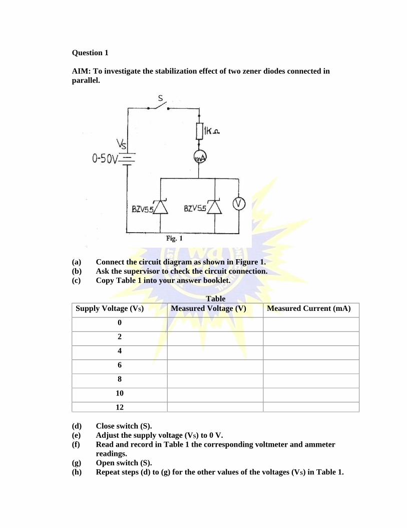
AIM: To investigate the stabilization effect of two zener diodes connected inparallel.
(a) Connect the circuit diagram as shown in Figure 1.(b) Ask the supervisor to check the circuit connection.(c) Copy Table 1 into your answer booklet.
TableSupply Voltage (VS) Measured Voltage (V) Measured Current (mA)
0
2
4
6
8
10
12
(d) Close switch (S).(e) Adjust the supply voltage (VS) to 0 V.(f) Read and record in Table 1 the corresponding voltmeter and ammeter
readings.(g) Open switch (S).(h) Repeat steps (d) to (g) for the other values of the voltages (VS) in Table 1.

(i) Plot a graph of the measured voltage (V) on the vertical axis against themeasured current (mA) on the horizontal axis.
(j) State the voltage at which the stabilization effect started.(k) From the graph in step (i), briefly comment on the experiment.
Experiment one tested the reverse characteristic of two 6V zener diodes connected inparallel across a voltage source.
Majority of the candidates obtained good results but were not able to state thestabilization voltage and comment on the experiment.
The performance of the candidates was general fair.
Question 2
AIM: To investigate the stabilization effect of two zener diodes connected in series.

(a) Connect the circuit diagram as shown in Figure 2.(b) Ask the supervisor to check the circuit connection.(c) Copy Table 2 into your answer booklet.
TableSupply Voltage (VS) Measured Voltage (V)
0
8
12
16
20
12
(d) Close switch (S).(e) Adjust the supply voltage (VS) to 0 V.(f) Read and record in Table 2, the corresponding voltmeter reading.(g) Open switch (S).(h) Repeat steps (d) to (g) for the other values of the voltage (VS) in Table 2.(i) Plot a graph of the output voltage (V) on the vertical axis against the supply
voltage (VS) on the horizontal axis.(j) State the voltage at which the stabilization effect started.(k) Briefly comment on the result of the experiment.
Majority of the candidates failed to recall the concept that the two diodes breakdownvoltages will add up to 12 V before stabilization voltage.
Performance of the candidates was generally fair.

INFORMATION AND COMMUNICATION TECHNOLOGY(ELECTIVE) 2
1. GENERAL COMMENTS
This paper happened to be the third May/June ICT (Elective) paper 2 administered. Thestandard of the paper compared favourably with the previous papers in the areas ofcontent and level of difficulty.
The paper was well within reach of the candidates and the general performance was notmuch different from that of the first two.
On the whole, the performance was just average.
2. A SUMMARY OF CANDIDATES’ STRENGTHS
(1) In general, candidates responded to the questions as demanded by the rubrics.
(2) A few candidates exhibited good knowledge of the subject matter.
(3) A greater number of candidates expressed themselves much better in the EnglishLanguage than exhibited before.
3. A SUMMARY OF CANDIDATES’ WEAKNESSES
The following were the main candidates’ weaknesses identified:
(1) Inability to appreciate the key requirements of the questions.
(2) Apparent inadequate preparations.
(3) Little or no evidence that candidates planned answers before writing them down.
(4) Poor communication skills.
(5) Some of the candidates had bad handwriting.
(6) Some candidates demonstrated in their answers that they had little or noknowledge of the examination syllabus.

4. SUGGESTED REMEDIES
(1) Candidates should carefully read through the questions, selecting those to beattempted and planning the answers before writing them out.
(2) Candidates should learn with suitable textbooks and material on ICT andcarefully use the Internet as a learning tool.
(3) Candidates should avoid the use of inappropriate standards of communicationsuch as those on the various social media platforms.
(4) Candidates should allow for time to read through their answers to correct anyerrors as well as add further details.
(5) Teachers of the ICT Elective subject should learn to adhere to the syllabus asmuch as possible.
5. DETAILED COMMENTS (QUESTION BY QUESTION)
Question 1
(a) What is e-learning?(b) State five advantages of e-learning.(c) Outline three constraints in using multimedia for teaching.
Majority of the candidates answered the (a) and (b) parts fairly well but (c) waspoorly tackled by almost all the candidates. The following is the solution:
(a) E-learning is the use of electronic educational technology in teaching andL earning.
(b) Advantages of e-learning:(i) Facilitates distance education.(ii) Reduces travel time and cost.(iii) Teaching and learning can be extended to a larger audience.(iv) Classwork can be scheduled around work and family.(v) Teaching and learning can take place at any location.(vi) Students can work at their own pace.(vii) Easy communication between students and teachers and vice versa.
(c) Constraints in using multimedia:(i) Absence of electrical power supply.(ii) Non-acceptance of digital culture.(iii) Lack of user’s familiarity with equipment.

(iv) Resistance to change.(v) Non-availability of digital equipment.
(vi) Lack of appropriate skills of both teachers and students.(viii) Lack of time required to plan, design, develop and evaluate multimedia
activities.
Question 2
State five features of:(a) an electronic spreadsheet application;(b) a QBASIC programming language.
Almost all the candidates who attempted this question got the requirements entirelywrong. They approached both parts of the question in terms of what is seen on thecomputer screen when a spreadsheet program is launched and the essentials of QBASIC.
The required solution follows:
(a) Features of an electronic spreadsheet application:(i) Supports the idea of variables.(ii) Use of formulae.(iii) Use of functions.(iv) Supports ‘what if?’ analysis.(v) Provides a wide range of graphs.(vi) Dynamic calculations.
(b) Features of a QBASIC programming language:(i) Simple and easy to learn.(ii) Automatically checks syntax.(iii) Automatically capitalizes the reserved words.(iv) Allows users to break lengthy programs into modules.(v) Has dynamic program debugging feature.(vi) Supports local and global variables.(vii) Interprets a statement at a time to the CPU.(viii) Contains two windows – program window and immediate window.(ix) Can run nearly under all DOS and Windows operating systems.
Question 3
(a) A Ghanaian company operating in Nigeria has its files on a storage system inAbuja. The company’s backup files are kept on another storage system inAccra.(i) State the two storage systems involved.(ii) Give one reason for these different storage locations.

(b) (i) List three components of the central processing unit.(ii) State a function each of the three components listed in 3(b)(i).
Most of the candidates, for (a), referred to Primary and Secondary storage – completedeviations.
The suggested solution is as follows:(a) (i) - Main Server/Database Server/File Server.
- Backup Server/Database Server/File Server.
(iii) The company keeps its backup in Accra so that it can easilyrecover/restore lost or damaged documents in case of any disaster inAbuja.
(b) (i) Components of the Central Processing Unit:- Arithmetic Logic Unit- Register- Control Unit- Memory Unit
(ii) Function of component:- Arithmetic Logic Unit: Carries out the arithmetic e.g. Add, Subtract, Multiply and Divide. Performs certain logical operations e.g. Testing whether two data
items match.
- Register: Data and instructions pass in and out of the processor through the
memory data register (MDR). All data and instructions pass in and out of main storage through the
memory buffer register (MBR). I/O devices connected to the processor via a bus also have a data
buffer register which serves a similar purpose as the MBR.
- Control Unit: The nerve centre of the computer. Co-ordinates and controls all hardware operations. Deals with each instruction in turn in a two-stage operation called the
fetch-execute cycle.
- Memory Unit: Memory buffer that temporarily stores data the processor needs,
allowing the processor to retrieve the data faster than if it came frommain memory.
Holds random data, usually on first in first out, or first in last out basis.
Question 4
State five roles of information in the society.
A good number of the candidates were preoccupied with the attributes of usefulinformation, viz. accuracy, timeliness, etc., an indication that they did not pay attention tothe requirements of the question.
The recommended solution is:
The roles of information in the society include:
1. Keeping people informed on current issues.
People, both in and outside the corporate institution, require information for them tobe abreast with current events that may directly or indirectly impact on what theyengage in.
2. Proving facts for decision making.
Individuals, especially managers, depend on some amount of information to enablethem make the decisions required of them. Information, it is said, is the trigger forthe decision making process.
3. Making facts available for a firm to compete effectively in its industry.
The management of an organization need information on other firms within itsindustry in order to craft strategies for effective competition.
4. Facilitating plans for development.
The government needs information to enable it come up with plans for infrastructuraland other development projects.
5. Enabling business decisions on what will make organisations more successful.
Information on demand and supply, for example, will make it possible for themanagement of organisations to decide on production and sales that will make foroptimum success.
6. Keeping the security agencies informed on relevant issues.
The security agencies require information that will help in their work of protectingthe state and individuals Such information may come from in or outside the country..

Question 5
Explain the following database terms:
(a) Field;(b) Query;(c) Record;(d) Design View(e) Datasheet View.
This was the question that attracted the worst of answers. The general knowledge ondatabase terminologies was extremely poor.
The suggested solution is as follows:
(a) Field: An element or column in a database table/file that contains a specific itemor information.
(b) Query: A question/request about the data stored in a database.
(c) Record: An element or row in a database/file that contains a collection of dataabout an item.
(d) Design View: A database window in which tables are designed for a database.
(e) Datasheet View: A database window that displays data from a table, form, report orquery for changes (e.g. editing, viewing, addition, deletion and searching) to beeffected.

INFORMATION AND COMMUNICATION TECHNOLOGY(ELECTIVE) 3
1. GENERAL COMMENTS
The standard of the paper and that of the previous years' examination is the same. It wasnoted that, candidates’ performance was better than the previous year.
It has, however, been observed that performances continued to be localized even thoughthe level has reduced, i.e. excellent performances are concentrated at certain schoolswhile bad performances are also concentrated at certain schools. The variance ofperformances at localities is insignificant.
This year has continued to see candidates scoring high marks in the HTML andDatabase. The Excel question was poorly attacked. Candidates had problems with the taxcomputation and the cell protection.
2. A SUMMARY OF CANDIDATES’ STRENGTHS
(1) Candidates were able to enter data.(2) Candidates were able to code HTML.
3. A SUMMARY OF CANDIDATES’ WEAKNESSES
(1) An insignificant few number of candidates used Microsoft Excel for the databaseapplication.
(2) Some candidates did not name objects properly.(3) Usage of the header facility in the table was not good.(4) Many candidates were unable to create the database relationships.(5) Candidates had difficulty in protecting excel cells.(6) Candidates could not correctly calculate tax.(7) HTML files were saved as “.txt” files.
4. SUGGESTED REMEDIES
(1) Teachers must cultivate logical reasoning skill in candidates to help in thedevelopment of programming skills.
(2) Teachers must pay attention to the curriculum .They must stress on technicalapproach in teaching ICT.
(3) Candidates must be encouraged and assisted to pick up personal ICT projectsstructured in a manner which will compel them to eventually be practical in theirapproach to the subject and cover significant aspects of the subject.

5. DETAILED COMMENTS (QUESTION BY QUESTION)
Question 1
HTML
The question required candidates to create an html web page. It required the use of a TextEditor.
The solution to the question is expected to follow the pattern explained below.
HTML is a standard and the layout follows a specific structure to allow for correct interpretationfor presentation. The structure of an html document is as follows:
<!DOCTYPE html><html><head><title>Title of the document</title></head>
<body>The content of the document......</body>
</html>
It must be noted that the title is part of the head tag. Placing it outside the head is not a correctstructuring even though you can have the title correctly displayed.
The body tag is not part of head tag as some have sort to do.Even though an example of indentation has been given in the question, candidates still fail toindent properly.
Indentation is not considered critical for the structure tags i.e. html, head, title, and body, but thelines coded between the opening and closing sets of any of the tags are critical.
NOTE: <ol> …</ol> is the tag for Ordered HTML Lists. <li>…</li> is the tag for listing theitems one by one. Note that the <ol> and </ol> tags are aligned vertically while <li> and </li>tags are also aligned vertically but pushed inside the <ol>..</ol> tag. i.e. indented.
The arrangement<p><u>Items</u></p>

has been given in the question as an example, yet, candidates did not performindentation.<p>….</p> is a set of paragraph tags. Within this paragraph a content of theparagraph is entered as Items. This content is underlined using the <u>….</u> set of tags.
At the completion of the work candidates work will look similar to the codes below:
<!DOCTYPE html><html><head><title>
Candidates' name and Index Number goes here</title></head>
<body><p>
My top THREE subjects are:</p>
<!-- List the items using Ordered HTML Lists as implied in the lineabove. -->
<ol><li> Mathematics </li><li> English Language </li><li> Life Skills</li>
</ol>
</body>
</html>
Some candidates used wrong tags such as<li1> Mathematics</li1><li2>English Language</li2><li3>Life Skills</li3></html><UI> MATHEMATICS</U1><U2> ENGLISH </U2>
Some HTML files were coded correctly but saved as text files. The editor used seems to havehad a default “.txt” extension. It added it to the ORDERED_LIST.HTML typed by the candidate.
With the use of unclosed title tag and nobody tag some candidates had all their content shown inthe title during display.

Question 2
EXCEL
Candidates were not able to carry out this work except for an exceptional few.
a. Some created the tables in Access.
b. This question requires candidates to formal the cells under Monthly_Salary, Tax andNet_Salary columns to have the 1000 separator(,), two decimal places and the GhanaCedi symbol (GH¢).
c. Tax calculation is not done by just picking the gross and looking at the range it fits in forthe percentage to be applied. The application of tax rates is done by splitting the salaryinto the five tax ranges and applying the appropriate tax rate and finally summing up thetaxes to arrive at the final tax.
Candiates may also use cell functions to introduce a comditional computation of thetaxes.This requires programming skills.
d. For the calculation of Net_Salary, the formula was given as:
Net_Salary = Monthly_Salary – Tax
e. For the cell protection, any entry in any column apart from the Monthly_Salary columnwill provide an error message on-screen. The following steps can be followed to effectthis protection:
(1) Select cells to be unlocked after protection(2) Unlock these cells(3) Remove the check against “Lock”(4) Protect the worksheet
Question 3
DATABASEa. The requirement is to use a database application to create a database of student data and
name it TERM in the folder created.
The exact naming of the database is critical. Its placement in the folder created iscritical. You can manually search for a document on the computer through varioustechniques even if you forgot the name. However, during the execution of a program,the name and its location must be exact otherwise the program cannot find it.

Some candidates used Microsoft Excel to answer this question which was wrong.
b. Three tables were required to be created defining the fields appropriately:-STUDENTDETAILS, SUBJECT, and SUBJECTSELECTION.
Defining the fields appropriately implies that the field names must be correct and theirdata types must be correct. A table with wrong field data types is not a correct table.
Some candidates did not name the tables properly. Others defined all fields as type Text.This is not correct in some instances.
c. Appropriate keys are to be used in the created tables to create the relationships among thethree tables.
To finally link the relationships, select the primary key from STUDENTDETAIL tableand dragg it to the same field in the SUBJECTSELECTION table.
Repeat the steps and create the relationship betwen the primary key in the SUBJECTtable and the SUBJECTSELECTION table. The result is as follows:
d. Calculations of BMI is to be saved as QRYBMI.The formula for the calculation wasgiven as :
BMI = WEIGHT--------------------------
HEIGHT X HEIGHT
The query in sql view is as follows:
SELECT STUDENTDETIAL.[INDEX _NO], STUDENTDETIAL.[STUDENT_NAME], STUDENTDETIAL.[DAT-OF _BIRTH], STUDENTDETIAL.HEIGHT,STUDENTDETIAL.WEIGHT, ([WEIGHT]/([HEIGHT]*[HEIGHT])) AS QRYBMIFROM STUDENTDETIAL;
Some candidtes missed the use of the brackets in code expression of the formula for thecomputation of the BMI.

METALWORK 2
1. GENERAL COMMENTS
Generally, the standard of the paper and candidates’ performance compared favourablywith those of previous years.
2. A SUMMARY OF CANDIDATES’ STRENGTHS
The responses of some students were encouraging.
3. A SUMMARY OF CANDIDATES’ WEAKNESSES
Majority of the candidates could not sketch properly.
4. SUGGESTED REMEDIES
Teachers should give enough activities involving sketching to students.
5. DETAILED COMMENTS
Question 1
(a) State four sources of danger in the workshop.
(b) In a tabular form, classify the following into ferrous and non- ferrous metals:(i) Copper;(ii) Zinc;(iii) Wrought iron;(iv) Brass;(v) Aluminium;(vi) Lead;(vii) Carbon steel;(viii) Cast iron.
(c) State one use each of the following:(i) Lead;(ii) Wrought iron.
(a) This part of the question required candidates to state four sources of danger in theworkshop. Majority of the candidates provided good sources of danger.
(b) The classification of the given metals into ferrous and non-ferrous metals and in atabular form was done properly by some candidates, however, some candidatesfailed to prepare the table.

(c) Candidates could state one use each of lead and wrought iron.
Question 2
(a) Explain the following operations:(i) Drilling;(ii) Grinding.
(b)
(i) Identify the machine shown in the sketch above.(ii) Name the parts labelled U, V, W, X and Y.
(c) Make a sketch of a curved snips.
(a) Some candidates could explain drilling and grinding operations.
(b) Majority of the candidates could identify the machine shown in the sketch andwere able to name the parts labelled U, V, W, X and Y.
(c) Majority of the candidates could not sketch curved snips.
Question 3
(a) State the results of the following operations:(i) Quenching hot carbon steel in water;(ii) Heating mild steel in a box full of carbon.
(b) Explain why patterns are slightly made oversized.(c) List three types of fuel used in forging.(d) Sketch the following forging tools:
(i) flatter;(ii) hot sett.
(a) Performance generally was good since candidates could state the results ofquenching hot carbon steel in water and heating mild steel in a box full of carbon.
(b) Some candidates could not explain why patterns are slightly made oversized.
(c) Candidates could list three types of fuel used in forging.
(d) Majority of the candidates could sketch the flatter and hot sett correctly.
(e) Some candidates were able to state one use each of the tools sketched in (d)above.
Question 4
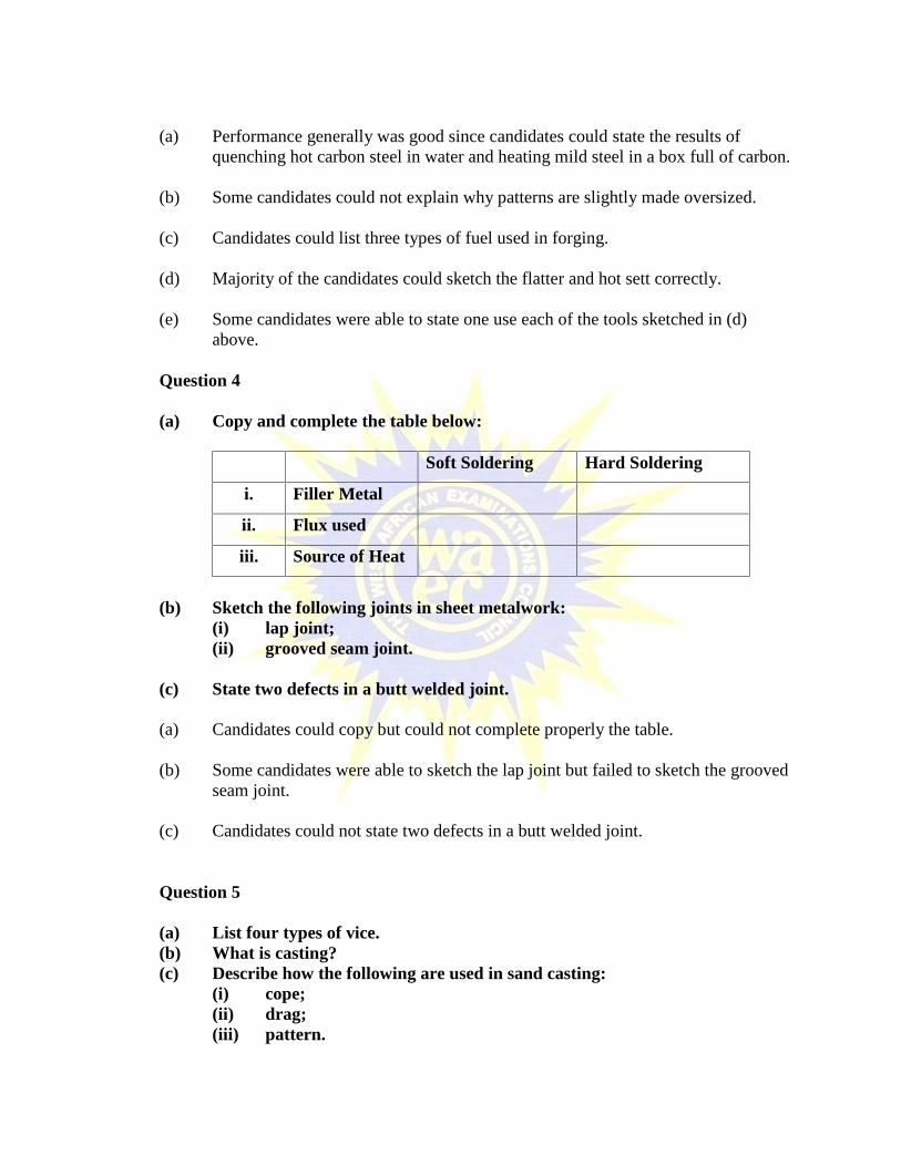
(a) Copy and complete the table below:
Soft Soldering Hard Soldering
i. Filler Metal
ii. Flux used
iii. Source of Heat
(b) Sketch the following joints in sheet metalwork:(i) lap joint;(ii) grooved seam joint.
(c) State two defects in a butt welded joint.
(a) Candidates could copy but could not complete properly the table.
(b) Some candidates were able to sketch the lap joint but failed to sketch the groovedseam joint.
(c) Candidates could not state two defects in a butt welded joint.
Question 5
(a) List four types of vice.(b) What is casting?(c) Describe how the following are used in sand casting:
(i) cope;(ii) drag;(iii) pattern.

(a) A few of the candidates could list four types of vice. Types of vice include, pin,leg, machine, bench and hand.
(b) Performance was good.
(c) Candidates could describe how to use cope, drag and pattern in sand casting.
METALWORK 3
1. GENERAL COMMENTS
Generally, the candidates performed extremely well and the exercise was quitemanageable. Candidates could complete the exercise within the specified time.
Candidates’ performance could be compared with those of previous years and there hadbeen a vast improvement in their practical skills.
The marking scheme used in the marking recognized all levels of performance andawarded marks fairly and accordingly.
2. A SUMMARY OF CANDIDATES’ STRENGTHS
(1) Candidates had showed great improvement in their abilities - of using variouscutting tools, to cut out the given shapes/forms.
(2) Candidates also produced neat and clean filings.(3) Candidates adhered to safe working practices – this was manifested in the
artefacts the candidates produced.
3. A SUMMARY OF CANDIDATES’ WEAKNESSES
(1) Some candidates were deficient in accurate performance – they worked quiteabove the given tolerance.
(2) They lacked effective control of cutting tools – filing was excessively carriedthrough.
(3) Some candidates still keep burrs and sharp edges on their finished work.(4) Candidates failed to smear oil on parts filed.(5) Bags used to pack finished work were not produced to the specified dimensions –
This made handling difficult especially when test items had to be removed fromthe bag.
4. SUGGESTED REMEDIES
(1) Candidates should be encouraged to mark out the work profile using the givendimensions from a working drawing first before attempting to cut through thescribed and dot punched lines.
(2) Candidates should be encouraged to finish workpieces by removing all burrs andsharp edges.
(3) Candidates should be provided with the necessary tools, equipment and materialsto enable them produce neat and clean work.
5. DETAILED COMMENTS
Candidates were provided with two practical questions, and candidates wererequired to answer any one of the two questions – either Question 1 which involvedexercise in fitting, or Question 2 covering exercise in machinery.
Question 1 -FITTING EXERCISE
PART A
Candidates were given one flat mild steel plate, 82 mm x 62 mm x 3 mm to producethe shape shown as Part A in the working drawing.
The candidates were expected to file work to the given overall dimensions 80 mm x60 mm. After obtaining the true rectangular shape, the candidates were expected tomark out the shape or profile accurately on the flat mild steel plate.
The candidates would be further required to dot punch through the scribed linesbefore attempting to cut out the shape for further smooth filing to get close to thespecified size within the given tolerance.
The inner part of the fork could be drilled out before completing the cut with a flatchisel. Clean file the chiselled slot to complete the part.
PART B
Candidates were expected to cut this square piece measuring 40 mm x 40 mm fromthe given mild steel plate of 42 mm x 42 mm x 3 mm. It meant that the candidateswere expected to file 2mm metal from the given work piece to obtain the final size of40 mm x 40 mm.
The sharp edges ought to be removed to facilitate assembly of the two parts.
The fit between Part A and Part B in assembly ought to result in transition fit.
Majority of the candidates were able to follow the correct procedures to produce theoverall assembly.
Question 2 - MACHINING EXERCISE
Candidates were supplied with one piece free cutting mild steel rod, Ø50 mm x 80mm to produce a simple machined part per the given working drawing: Ø45 x 65mm.
This consisted of two shoulders of 15 mm each with a middle shaft of Ø35 x 35 mm.The two shoulders Ø45 x 15 mm were to be knurled with diamond knurling tool.
In addition to the aforementioned features, candidates were expected to drill a Ø15hole at the middle of the 35 mm shaft.
Majority of the candidates failed to attempt this question probably due to lack of therequisite machines and tools to produce the work.
The few candidates who attempted this could not do any extraordinary work as comparedto candidates who attempted the fitting exercise.
TECHNICAL DRAWING 2
1. GENERAL COMMENTS
Candidates’ performance compared with those of previous years were on the average.The standard of the paper, that is, quality of questions and the marking scheme wereperfect and precise.
Generally, candidates did well in the selection of questions and penial work were on theaverage.
2. A SUMMARY OF CANDIDATES’ STRENGTHS
Most candidates used the correct grade of pencils for their drawings. TheOutlinesof objects were clearly differentiated from the construction lines. Thepencil work was neat. Hatch lines were drawn to the correct spacing and to theangle of inclination, i.e for producing the shear force diagram in Question 5.Where some of the given views were to be copied, candidates did well in suchsituations. For Question 5, the scale conversion and arrow heads wereappropriate and neatly done.
3. A SUMMARY OF CANDIDATES’ WEAKNESSES
Few candidates still used BB pencils for their drawings and the output was dirty.Outlines of objects and construction lines could not be clearly identified, both lines weresimilar in thickness. The given elevation for question one was poorly copied. Themiddle portion K of the pipe was wrongly drawn thus the development of K was poor.Projection lines were not at right angles to the edge. The divisions on the pipe diameterwere not on the same as that on its circumference. Candidates copied the two givenelevations instead of the isometric projection. The lowest point P was wronglypositioned; the faces were poorly produced, the cylinder was placed opposite withdifferent dimensions and the slot omitted. Candidates could not draw the isometriccircles at the ends of the cylinder, some used freehand whilst others produced completecircles. Construction of the true length; the given views were inaccurately produced.The horizontal distance was either more or less than the given 80 mm. This affected theinclination of the line in the elevation. Some used freehand to draw the arc. The verticaltrace was wrong the others did not show it at all. The candidates who attempted question5 did poor work. The beam was not drawn to the correct scale. The scale conversion waswrong. The arrow heads were poorly drawn. The force lines were represented with dotsand straight lines. Candidates could not draw parallel lines to each other, especially whendrawing parallel lines under the space diagram to that of the radial lines in force diagram.

4. SUGGESTED REMEDIES
The recommended pencils for Technical Drawing are HB and HH and not the BB.Candidates should know the types of lines and their applications, e.g the constructionlines and outlines. Candidates should read, understand and digest each question verywell. Question 2 required the construction of an ellipse using the major axis and thedistance between foci points. But candidates used the distance between the foci as theminor axes and produced poor construction. Candidates should practise all the methodsfor constructing ellipse. Question 3 required conversion of orthographic projection toisometric. The lowest point P was not used, thus candidates produced different views,some drawing it as oblique production. The isometric axes should be drawn firstfollowed by the overall dimension to produce the isometric box in which the object couldbe drawn bearing in mind the placement of the lowest point. The true length of line couldbe obtained using either rabatment or auxiliary method. Ideally the rabatment methodcould give a better vertical and horizontal traces. Question 5 required the conversion ofthe given beam length and the three forces to the appropriate lengths in mm. Length ofthe beam 2000 mm became 100 mm (scale 1 mm = 20 mm) and forces 20 KN, 25 KNand 10 KN ) were converted to 20 mm, 25 mm and 10 mm (scale 1 mm = 1 KN)respectively. Drawing parallel lines to radial lines from the force diagram are bestproduced using set squares. Candidates are advised to practise more work on parallellines.
5. DETAILED COMMENTS
Question 1
Draw the given front elevation. Project from the elevation to obtain plan. Divide theplan into equal parts, preferably 12. Project from the numbered points on thecircumference to the two joints of the middle pipe K. Draw at right angles to theintersecting points on K a length of circumference of the pipe. Divide the baselength into the same number of division on plan. Locate the correspondingintersecting points of the perpendicular and that from the joints on K. Drawsmooth curves through the points to obtain the development.
Candidates who produced the elevation correctly were few and they did well for thedevelopment. Other candidates did poor work on the joints of pipe K. Theinterpenetration was not well inclined at the correct angles. Thus the projections toobtain the circumferences for both on top and bottom were wrongly done. Somecandidates divided the circumference more than that on the plan. There pencil work wasnot encouraging.

Question 2
Construction of Ellipse, normal and tangentThe major axis, 120 mm, is drawn and divided into two equal parts. From the midpoint of the major axis a distance 40 mm is measured at both sides to obtain the focipoints (i.e the distance between foci is 80 mm apart). With foci points as centres anda radius 60 mm (i.e half the major axis) draw arcs to intersect each other at both ontop and below the major axis. The distance between the points of intersections givesthe minor axis. The construction of the ellipse could then be constructed using therectangular, concentric or the trammel method since the major and minor axes areknown. Use any method for the ellipse construction. Point ‘P’ above the major axisand at 35 mm to the right of the minor axis is located. Join the foci points to point Pand bisect the angle to obtain the normal. Draw perpendicular at point P to thenormal for tangent.
Few candidates drew the ellipse with the normal and tangent to perfection. Others drewthe ellipse but were unable to construct the normal and tangent. The rest of thecandidates who attempted the question used freehand to produce the ellipse. Some didnot construct the tangent but used straight edge to draw it. Generally, most candidateswho used the correct method for the ellipse did not state the length of the minor axis.
Question 3
Isometric Projection of the blockVisualize the two given views as an object and produce a freehand sketch of theobject. Draw isometric box with the overall dimensions (100 x 100 x 120) mmbearing mind the position of the lowest point P. The number of fces produced whenthe block is perfectly drawn are thirteen.
Few candidates’ drawings were excellent. Others did a good work but did not use thelowest point P. Some candidates did poor work. The two webs were omitted and theisometric circles were drawn as full circles using a pair of compasses, others usedfreehand for producing the isometric circles.
Question 4
True views of a line.There are two methods for producing the true length of the line (auxiliary andrabatment). One point of the line in the elevation is used as a centre and a radiusequal to the length of the line is used to draw an arc down to intersect the horizontalline from the centre point. A straight line is projected down from this point ofintersection down to cut the extended line from the other point of the line in the planview. The distance between the intersecting point and the stationary point give thetrue length of the line. The traces of the line are produced by extending both lines tointersect the joint of the two planes.
Few candidates attempted the question and di average work. Other candidates used theauxiliary method and did fair work. Candidates are advised to practise more work on thetrue and traces of lines. Some used freehand for drawing arcs instead of using a pair ofcompasses.
Question 5
Simply supported beam
The Space DiagramDraw the given beam of length 2000 mm to 100 mm (i.e scale 1 mm = 20 mm).Locate the three loads and the reactions at the correct positions. Label the spaceswith Bow’s Notation.
Determination of the ReactionsDraw the force line (scale 1 mm = 1 KN) and locate the pollar distance of 50 mm.Draw radial lines to obtain the force diagram. Draw parallel lines to the radial linesunder the space diagram to obtain the link or furnicular polygon. Draw a parallelline from the p0olar point to the closing line of the furnicular polygon to intersectthe force line. The intersecting point on the force line gives the magnitudes of thetwo reactions. Measure and convert the lengths into forces. (scale 1 mm = 1 KN).
Shear force diagramReverse the shear force diagram and draw horizontal lines through the five pointson the force line. The intersecting points of each of the horizontal line and that ofthe corresponding vertical line from the forces and the reactions give the points forthe shear force diagram. Draw outlines and hatch.
Few candidates’ work was excellent. Some of the candidates could not interprete thescale to draw the beam and position of the forces. Such candidates could not continuetheir work. Some candidates drew the space diagram but unable to construct the forceline (1 mm = 1 KN) thus the force diagram was poorly done. Those candidates whoproduced the force diagram poorly could not construct the link of furnicular polygon toperfection. Some did not draw the parallel line to the closing line of the furnicularpolygon. Thus the magnitudes of the reactions were left out. Majority of candidates’work on the shear force diagram was poor. Location of the vertical lines from the threeforces and two reactions were inaccurate. The hatch lines were uneven. None of thecandidates did not show the shear force under the 20 KN.
TECHNICAL DRAWING 3
1. GENERAL COMMENTS
The quality and the type of questions has been maintained as previous years. Theperformance of candidates as compared to the previous years was encouraging, especiallycandidates who offered mechanical drawing.
2. A SUMMARY OF CANDIDATES’ STRENGTHS
(1) General performance of candidates was encouraging as compared to previousyears.
(2) Candidates who offered mechanical engineering drawing scored higher marksthan those who offered building drawing.
(3) The draughtsmanship of a few candidates was highly recommendable.
3. A SUMMARY OF CANDIDATES’ WEAKNESSES
(1) Freehand sketching had always been a problem of candidates.(2) Identification and conversion of orthographic into pictorial isometric drawing is
also challenge.(3) Scaling was also a big challenge to candidates who offered the building drawing
option.(4) Most of the candidates drew with their own scale. Sectioning was not well done.(5) Identification of parts to be sectioned was also a challenge.
4. SUGGESTED REMEDIES
(1) Teachers should encourage the use of the scale rule in building drawing.(2) They should also set assignments frequently which will involve the use of the
scale rule.(3) Teachers should organize field trips for students to other workshops.(4) Constant sketching exercises of basic tools, to sharpen students sketching skills.(5) The use of teaching and learning materials like models, showing sections of
components can go a long way to give students better understanding of sectionalviews of machine components.

5. DETAILED COMMENTS
Question 1
The figure below shows two views of a block drawn in first angle orthographicprojection. Make a freehand pictorial sketch of the block, making X the lowestpoint.
Most candidates chose to use guided instruments to draw the block, which the rubricsexplicitly warned against and its unacceptable.
Few candidates drew in freehand which was commendable, but failed to give some of therequired details of the block. Greater number of candidates failed to identify the block tobe drawn.
Candidates’ performance was average
Question 2
Make a freehand pictorial sketch of a builder’s square
Most candidates who attempted this question did well by drawing the required tool,unfortunately few candidates drew in two dimensional views which was not required.Most of the candidates also ignored the calibrations on the tool.

Few of the candidates drew the engineer’s try square instead of the builder’s square.
Candidates’ performance was good.
Question 3
Make a neat freehand pictorial sketch of a Junior hacksaw.
Very few candidates attempted this question and it is evident in the answers provided thatthe candidates are not conversant with the tool or do not know the tool.
The few candidates who attempted the question drew various types of saws as theanswer.
Candidates’ performance was average.
Question 4
A sketch plan of a bungalow with accompanying specification from foundation toroof was provided. Candidates were asked to study the given specification anddraw to a scale of 1:100 a floor plan and a rear elevation. And to a scale of 1:50 asectional elevation on plane P – P.
Most candidates provided good answers to the question but provided the front view of thebuilding as the rear view. This means they did not understand the word rear which meantthe back view.
Scaling was also a problem in most cases, especially in the drawing of the sectionalelevation. Candidates could draw to the scale provided by the question.

The use of the BS 1149 for building drawing should be strictly adhered to, so as to usethe correct convention of materials and parts in drawing. It will be noted that, candidateswere not conversant with the BS (British Standards) code.
Question 5
The figure above shows the three views of a machine component in first angleprojection.Draw full size, the following:(a) front elevation;(b) sectional plan Y – Y;(c) section end elevation X – X.(Hidden details are required on the sectional views)
Sections was therefore in question, candidates had a few work to do, sectioning whichwas being tested was not explicit. This allowed candidates who attempted this questionfaired very well.
Candidates’ performance was generally good.

WOODWORK 2
1. GENERAL COMMENTS
The standard of the paper compared favourably with that of the previous year. There hasbeen a little improvement of candidates’ performance over that of the previous year.
2. A SUMMARY OF CANDIDATES’ STRENGTHS
(1) Production of neat drawings;(2) Good dimensioning of drawings;(3) Good pencil work.
3. A SUMMARY OF CANDIDATES’ WEAKNESSES
(1) Inability to draw border lines and title blocks.(2) Lack of knowledge in the use of machines for preparing timber for work.(3) Candidates’ non-adherence to instructions or rubrics of the examinations.
4. SUGGESTED REMEDIES
(1) Tutors should introduce students to the use of border lines and title block andinsist that candidates use them in their class exercises and end of termexaminations.
(2) Teachers should take students through the processes involved in the effective useof the various machines used in the workshop.
(3) Teachers should try as much as possible to treat all topics in the syllabus.(4) Teachers should impress upon candidates to strictly adhere to the rubrics of the
examinations.
5. DETAILED COMMENTS
Question 1
(a) The piece in Figure 1 is to be prepared using the following machines; jointer,radial arm saw, hicknesser and rip saw.Use a line diagram to show the improvement of the piece through themachines in the correct sequence.

(b) List four operations carried out on the circular saw machine.(c) Name two types of portable sander.
(a) Some candidates failed to realize that some of the machines could be used morethan once in the sequence of operations. Because the machines were four innumber, they produced only four steps. The correct sequence is:
Radial Arm Saw→Jointer→RipSaw→Jointer→Thicknesser→Radial Arm Saw
(b)&(c) Majority of candidates answered these questions very well.
Question 3
(a) List four manufactured boards.(b) Name one timber defect caused by each of the following:
(i) drying timber too rapidly;(ii) improper stacking.
(c) State two advantages of casein glue over animal glue.
(a) Candidates performed very well in this question. However, a few candidatesmentioned veneer which is not a board.
(b) This question was very popular among candidates and they performed very wellin the question.
(c) Candidates’ responses were not very apt to answer this question. Among therequired answers are:
(1) casein glue takes shorter time to prepare than animal glue;(2) casein glue is more resistant to water than animal glue;(3) casein glue is easier to apply/ use than animal glue.
Question 4
(a) Name the two wood lathe centres.(b) List two types of wood stain.(c) State one purpose of quality control in mass production.(d) Sketch an upholstery ripping tool.
This question was not popular among the candidates. Very few candidates attempted thisquestion. The required answers include:
(a) Wood Lathe Centre- live/drive centres- dead/tailstock centres.

(b) Types of Stain- oil stain- water stain- spirit stain
(c) Purpose of Quality Control- ensures products meet specifications- ensures that standard is maintained- dictates and corrects faults
(d) Most candidates could not sketch the upholstery ripping tool. They rathersketched different types of chisels used in woodwork.
SECTION B
Question 1
Design an open wall cabinet to be used in a school’s sport office. The cabinet hastwo partitions and two shelves. It is made with 18 mm plywood.
The overall dimensions of the unit are:
Width - 450;Depth - 200;Height- 300.
(All dimensions in millimetres)
Make two preliminary freehand pictorial sketches each for a different design of thecabinet.
Candidates were able to produce the preliminary sketches. A few however failed toproduce the partitions and the shelves. Some candidates also produced only shelvesliving out the partitions. Again, candidates were to produce open wall cabinet, somecandidates provided doors thereby covering the partitions and shelves. Candidates shouldendeavour to work to satisfy the specifications given.
Question 2
Select one of the sketches in Question1 and indicate the selected sketch with a tick(√). To a scale of 1:5;
(a) (i) draw the isometric view;(ii) dimension the view indicating the sizes of the members and
compartments.(b) Name two joints to be used in constructing the cabinet.

(a) Most candidates were not able to draw the selected sketch in an isometric view,which is the 30º slant. Some drew in oblique, perspective and orthographic. Indimensioning the object, a few candidates dimensioned the overall lengths andwidths and left out the components.
(b) Majority of candidates were able to name the joints used in constructing thecabinet.

WOODWORK 3
1. GENERAL COMMENTS
The standard of the paper compared favourably with that of the previous years. Thequestions were syllabic and were of the acceptable level of difficulty. Candidates’performance compares favourably with that of last year.
2. A SUMMARY OF CANDIDATES’ STRENGTHS
Most candidates demonstrated their strengths in:(1) good interpretation of working drawings;(2) marking-out objects accurately;(3) production of a very good work
3. A SUMMARY OF CANDIDATES’ WEAKNESSES
(1) Candidates’ failure to use well sharpened cutting tools;(2) Candidates’ inability to saw accurately on the marked line but in the waste.
4. SUGGESTED REMEDIES
(1) Teachers should teach students the basic techniques of sawing and chisellingaccurately through constant practice.
(2) Teachers should ensure that candidates use the correct and appropriate tools forevery operation.
(3) School authorities and teachers should be well to provide easy to work, straightgrain type of wood to make the practical test less cumbersome for the candidates.

5. DETAILED COMMENTS
Candidates were given working drawings of a mirror frame. They were required tointerpret the drawings and construct the mirror frame, using already preparedworkpieces.
The work involved the following processes:(a) construction of mitred corner bridle joint;(b) construction of stopped haunched mortise and tenon joint;(c) construction of through mortise and tenon joint;(d) rebating;(e) finishing.

(a) Mitred Corner Bridle Joint
This question was attempted by all the candidates. Some of them were able tomark-out accurately and produced remarkable good joints. However, a few of thecandidates lacked the requisite skills to cut and remove waste wood from the pinsand sockets and as a result produced very poor work.
(i) Cleaning of the sockets were not properly done, candidates used blindtools. Some sockets were cut larger than the pins and could not fitproperly.
(ii) Some candidates cut the pins on the stiles instead on the rails. Some pinswere also not centralized, were not cut to size and were not properlycleaned.
(b) Stopped Haunched Mortise and Tenon Joint
Majority of the candidates attempted this question. Some of them were able tomark-out accurately and produced very good joints. However, a few of themcould not provide the haunches. The few who provided the haunches were notout of proportion. Some of the candidates could not clean the mortises properlydue to their inability to sue well sharpened tools. The bottoms of both the mortiseand that of the haunching could not be cleaned properly. A few of the candidatesconstructed through mortises instead of stopped mortises whiles the rest couldonly cut ordinary common mortise and tenon joint.
(c) Through Mortise and Tenon Joint
The construction of the through mortise and tenon joints which form the base ofthe mirror frame was attempted by all the candidates. Some of the candidates didremarkably well in this question. However, a few of the candidates constructedstopped mortise and tenon joint instead of the through mortise and tenon joints.Others also constructed notch and barefaced tenon joint instead of the throughmortise and tenon joint.
(d) Rebates
About half of the candidates did not attempt this question. A few candidates wereable to provide accurate rebating, others provided shallow rebates with very roughbottoms and broken edges. A few others also provided grooves instead of rebates.
(e) Finishing
Candidates were expected to put all the workpieces together to form the completemirror frame. Clean up all the joints and marked-out pencil lines for a pleasantappeal.

(i) Assembling
Majority of the candidates were able to assemble the work, a few didpartial assemble and very few could not assemble but tied the workpiecestogether for easy identification.
(ii) Dressing
Almost all the candidates failed to dress the work to give it the neededappeal.
This has been a perennial problem.