Embed Size (px)
Citation preview
SHAPE MEMORY ALLOY ACTUATED MICRO-FLOW EFFECTORSFOR VORTEX MANIPULATION
F.C. Wong, C.A. Rabbath, N. Hamel, D. CorriveauDefence R&D Canada - Valcartier
Quebec, Qc, CauadaContact: [email protected]
N. LechevinUniversite du Quebec 11 Trois-Rivieres, Quebec, Qc
O. BoissonneaultNumerica, Quebec, Qc
S. ChenInstitute ofAerospace Research
National Research Council ofCanada, Ottawa, On
Received August 2006, Accepted March 2007No. 06-CSME-36, E.LC. Accession 2955
ABSTRACTSmart structures are seen as an enabling technology for designing innovative control actuation systems
for future missiles. In this study, the feasibility of employing shape memory alloy (SMA)~actuated miCroflow effectors to control the vortex shedding behaviour that produces side forces on slender body missilesis examined. Supersonic wind tunnel tests were performed on a slender fmless missile equipped withstatic micro-flow effectors on a conical nose to determine suitable configurations that could generatesignificant side forces. Shape memory alloy actuators for the flow effector were developed usingnumerical techniques and validated experimentally. Matching the force-displacement characteristics ofthe SMA actuator to the micro-flow effector force-displacement requirement was accomplished by acompliant transmission mechanism. The dynamic performance of the micro-flow effector was assuredwith a two-step variable structure control law. Closed-loop test results showed that the control law wascapable ofproviding effective displacement control up to 1.0 Hz.
MICRO-EFFECTEURS ACTIONNES PAR ALLIAGES AMEMOIRE DE FORMEPOUR LA MANIPULATION DES T9URBILLONS
RESUMELes structures intelligentes sont per~ues comme nne technologie qui permet la conception de
systemes d'actuation innovateurs pour les missiles de demain. Dans cette etude, la faisabilite desmicro-effecteurs actionnes par nn alliage it memoire de forme (AMF) a ete examinee. Ces microeffecteurs servent it la commande des tourbillons qui produisent les forces laterales aux missiles.Les tests ont ete effectues dans nne soufflerie supersonique avec nn missileeffile et sanS ailette.Le missile a ete dote de micro-effecteurs statiques sur nne nez conique pour determiner lesconfigurations qui peuvent generer des forces laterales significatives. Les actionneurs AMF ontete developpes avec les techniques numeriques et valides experimentalement. Lescaracteristiques. en force et deplacements de I'actionneur AMF ont ete harmonise avec lescomportements exiges par Ie micro-effecteur en utilisant nne transmission elastique. Laperformance dynarnique du micro-effecteur a ete assuree par nne loi de commande variable endeux etapes. Les resultats en boucle fermee ont montre que la loi est capable de contralerefficacement Ie deplacement du micro-effecteur jusqu'it I Hz.
Transactions afthe CSME Ide la SCGM Vol. 31, Na. 1, 2007 19
1. INTRODUCTION
New technologies in aerospace are often developed to increase the speed, range and maneuverabilityofaerovehicles while reducing the volume and weight of its components. Flight control actuation systemsfor missiles, for example, have been improved with the introduction of electromechanical systems toreplace large hydraulic or pneumatic systems. More recently, systems using smart structures conceptshave been examined to replace traditional control actuation systems (1), (2). If small control surfaces canbe placed at strategic locations on the body to influence the macroscopic downstream flow, it is possibleto create large aerodynamic forces that affect the body's attitude. Patel (3) demonstrated the effectivenessofeight deployable flow effectors to control the vortex shedding that produces yaw forces on a subsonicmissile. The flow effectors were situated concentrically on a missile nose cone and located 41 mm fromthe tip. The flow effectors measured 9 mm long by 0.8 mm wide by 3 mm high and were deployed 1 mminto the airstream by a pneumatic actuation system. Massey (4) showed that small pin flow effectorscould be employed to modify shOCk wave structures for supersonic projectile trajectory control. The pinswere located at the aft-end ofthe projectile and were displaced 3.3 mm into the airflow by a rockermechanism and a pneumatic actuator. Along similar lines, Patel (5) established the feasability ofusingspoilers that were situated on the boattail ofa subsonic projectile to promote flow separation as a meansfor flight control. The arc-shaped flow effectors varied in length from 10 to 50 mm and in height from 1to 2 mm. Actuation was achieved using electromechanical solenoids.
In Refs. (3) to (5), attention was focused on finding the flow effector configurations that would allowsignificant aerodynamic forces to be generated through the manipulation of flow structures. Little wasdone to develop a lightweight actuation system that could fit in constrained space of a missile or projectileto actuate the flow effector. Smart structures based on materials such as shape memory alloys offer theopportunity to create compact, solid-state actuation systems by virtue ofthe material's ability to convertelectricaI energy to mechanical energy within its microstructure. In this study, a nose-mounted floweffector actuation system to alter vortex shedding behaviour and subsequently control the side forces onslender missiles is presented. First, the aerodynamic basis for the flow effector's geometry, force anddisplacement requirements is provided. Then, issues concerning the actuator behaviour and design oftheforce-displacement transmission mechanism are discussed. Finally, the method used to obtain closed-loopcontrol ofthe flow effector displacement is presented.
2. BACKGROUND
A wind tunnel and computational fluid dynamic (CFD) study was performed to determine thegeometry and actuation reqnirements for a flow effector configuration that could alter vortex sheddingstructures to produce significant side forces on a missile body at moderate angles-of-attack.
2.1 Wind Tunnel Model
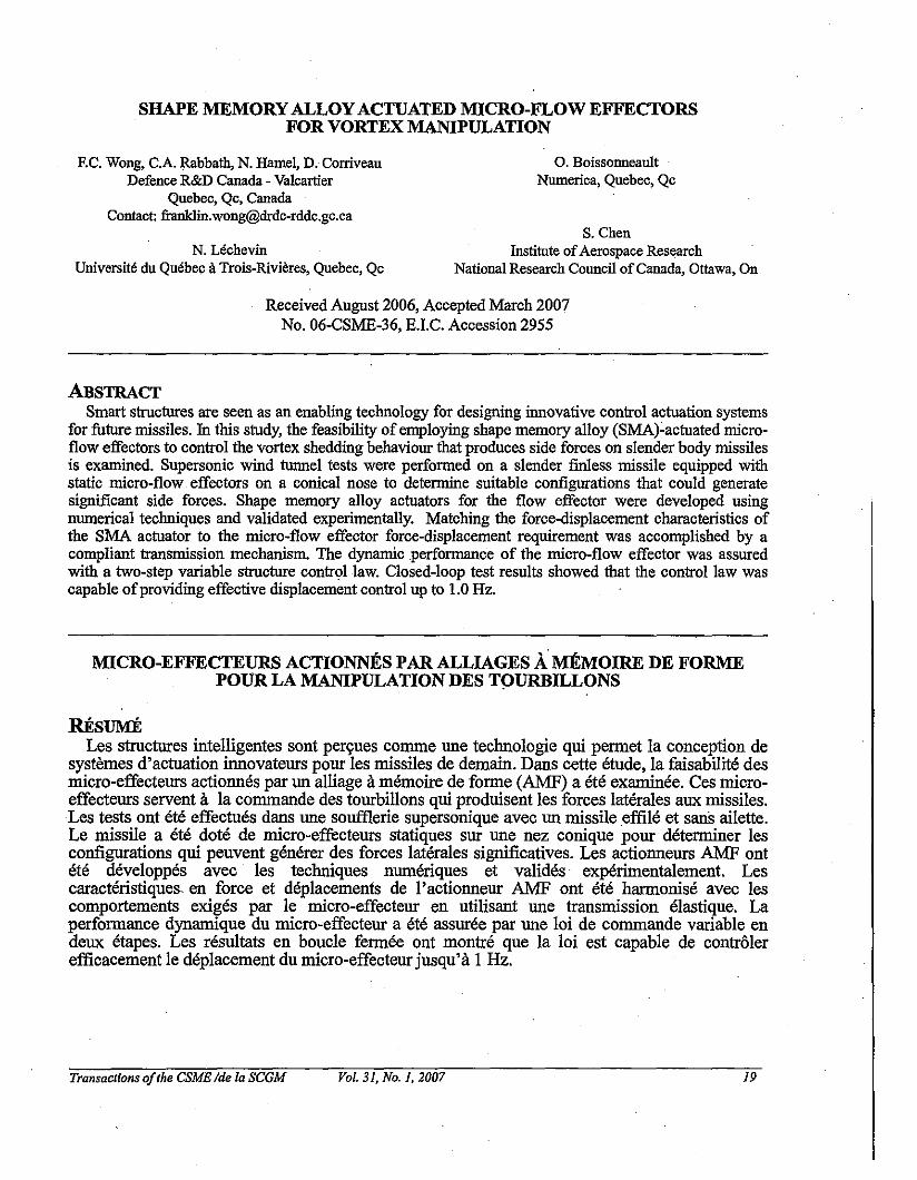
The baseline missile configuration is shown in Fig. 1. The model consisted ofa cylindrical bodyhaving a diameter of30 mm and length of300 mm with a conical nose that was 90 mm long.Trapezoidal-shaped flow effectors measuring 2.67 mm long by 1 mm high by 0.79 mm thick wereselected to disturb the flow along the nose and to create asymmetries that would induce side forces. Sincethe flow effectors were small in relationto the nose diameter and length, they were called micro-floweffectors.
Transactions ofthe CSME Ide la SCGM Vol. 31, No. 1,2007 20
E~·l-!!~-:.., ~ .. "" "'1--- ,I'
----- +--+--'.'!'!',;,....
-~---
LLril---r-
Figure 1: Missile and Flow Effector Configurations
The nose cone was eqllipped with disks onto which different configllrations ofstatic micro-floweffectors (also called keys) were mOllnted. The nose-disk assembly was designed sllch that the disks couldbe indexed in 45 deg. steps. One disk is located at a distance of25.32 mm from the nose tip whereas asecond row ofmicro-flow effectors is situated at 38.02 mm from the tip. For the purposes ofthisdiscllssion, only the resnlts ofthe single micro-flow effector, clean body (no fins) confignration will beshown. Discussion ofthe complete aerodynamic study may be fOllnd in (6) and (7).
2.2 - Experimental and Numerical Results
Aerodynamic data were obtained at a supersonic flow condition ofMach 1.5 for angles-of-attackbetween 0 and 20 deg. The results for the measured side force coefficients are shown in Fig. 2 fordifferent micro-flow effector angular positions as measured clockwise from the z-axis. Depending on theangular location ofthe flow effector, the magnitude ofthe side force coefficient varied between 0.06 to0.70. Furthermore, the variation in side force was symmetric for flow effector configurations located atcomplementary angular positions (e.g. 90 and 270 deg.). The lateral force coefficients increased as theangle ofattack increased with peak magnitudes occuring at an angle-of-attack between 15 and 20 deg.Following the peak, a redllction in lateral force was observed for all confignrations. The asymmetry in themagnitude ofthe side forces in the figure when comparing the port and starboard data is thought to becallsed a micro-asymmetry in the model and is not related to the micro-flow effectors themselves.
Transactions ofthe CSME Ide la SCGM Vol. 31, No.1, 2007 21
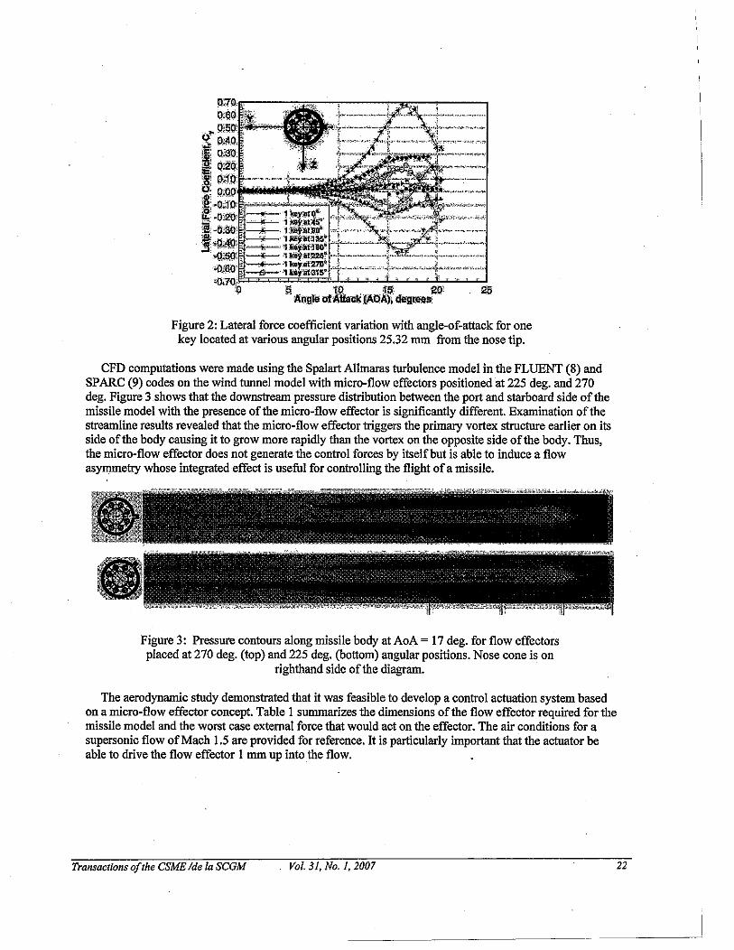
Figure 2: Lateral force coefficient variation with angle-of-attack for onekey located at various angular positions 25.32 mm from the nose tip.
CFD computations were made using the Spalart AIlmaras turbulence model in the FLUENT (8) andSPARC (9) codes on the wind tunnel model with micro-flow effectors positioned at 225 deg. and 270deg. Figure 3 shows that the downstream pressure distribution between the port and starboard side ofthemissile model with the presence ofthe micro-flow effector is significantly different. Examination ofthestreamline results revealed that the micro-flow effector triggers the primary vortex structure earlier on itsside ofthe body causing it to grow more rapidly than the vortex on the opposite side ofthe body. Thus,the micro-flow effector does not generate the control forces by itselfbut is able to induce a flowasymmetry whose integrated effect is useful for controlling the flight ofa missile.
Figure 3: Pressure contours along missile body at AoA = 17 deg. for flow effectorsplaced at 270 deg. (top) and 225 deg. (bottom) angular positions. Nose cone is on
righthand side ofthe diagram.
The aerodynamic study demonstrated that it was feasible to develop a control actuation system basedon a micro-flow effector concept. Table I summarizes the dimensions ofthe flow effector required for themissile model and the worst case external force that would act on the effector. The air conditions for asupersonic flow ofMach 1.5 are provided for reference. It is particularly important that the actuator beable to drive the flow effector I mm up into the flow.
Transactions ojthe CSME Ide la SCGM Vol. 31, No.1, 2007 22
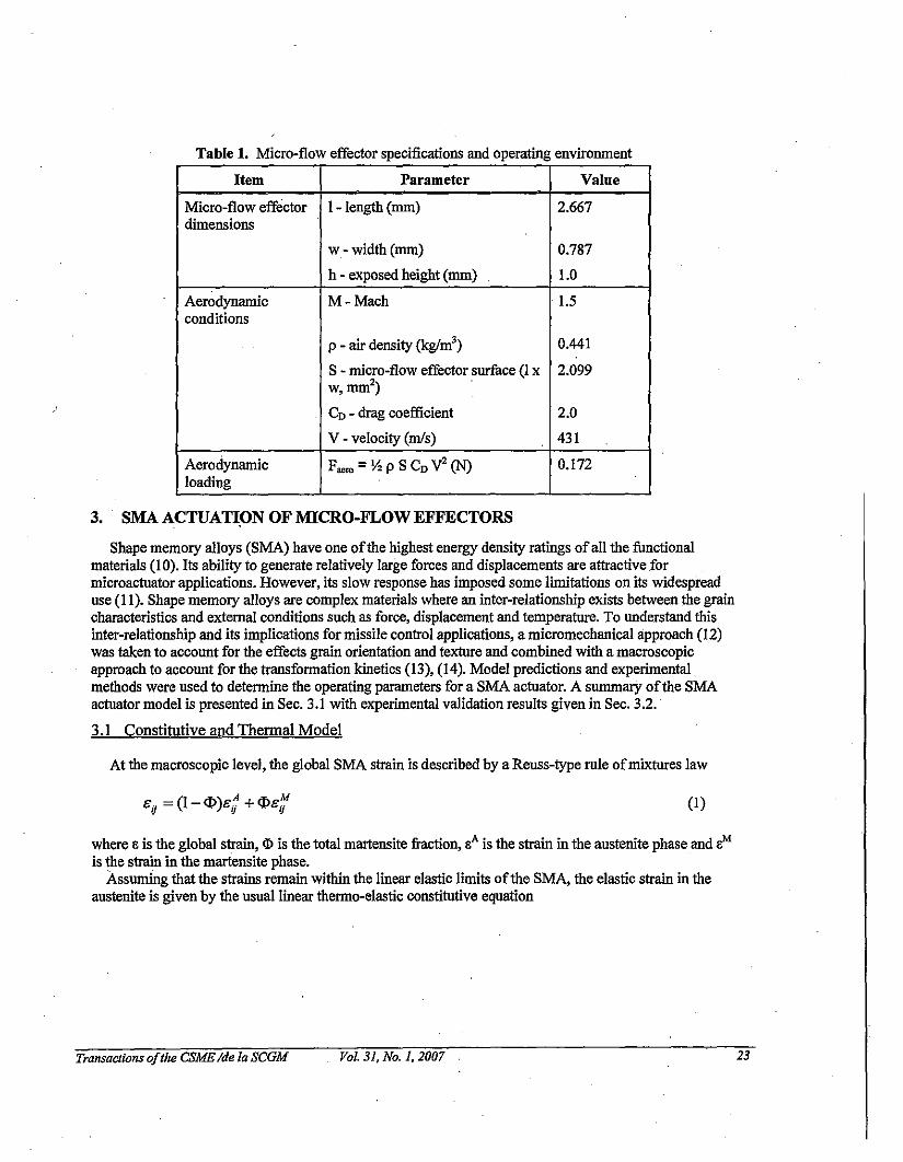
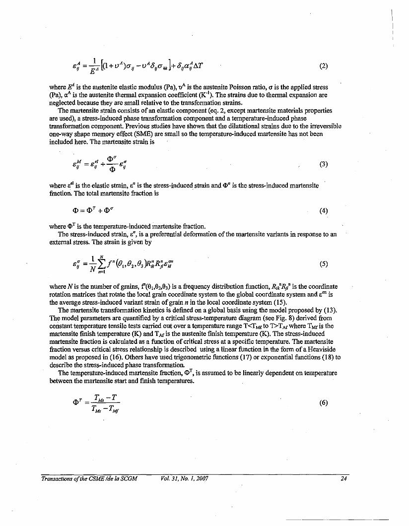
Table 1. Micro-flow effector specifications and operating environment
Item Parameter Value
Micro-flow effector 1- length (nun) 2.667dimensions
w - width (nun) 0.787
h - exposed height (nun) 1.0
Aerodynamic M-Mach 1.5conditions
p - air density (kglm') 0.441
S - micro-flow effector surface (l x 2.099w, nun2) .
CD - drag coefficient 2.0
V - velocity (mls) 431
Aerodynamic F"ro = Y:z p S CD V2 (N) 0.172loading
3. SMA ACTUATION OF MICRO-FLOW EFFECTORS
Shape memory alloys (SMA) have one ofthe highest energy density ratings ofall the functionalmaterials (10). Its ability to generate relatively large forces and displacements are attractive formicroactuator applications. However, its slow response has imposed some limitations on its widespreaduse (II). Shape memory alloys are complex materials where an inter-relationship exists between the graincharacteristics and external conditions such as force, displacement and temperature. To understand thisinter-relationship and its implications for missile control applications, a micromechanical approach (12)was taken to account for the effects grain orientation and texture and combined with a macroscopicapproach to account for the transformation kinetics (13), (14). Model predictions and experimental.methods were used to determine the operating parameters for a SMA actuator. A summary ofthe SMAactuator model is presented in Sec. 3.1 with experimental validation results given in Sec. 3.2.
3.1 Constitutive and Thermal Model
At the macroscopic level, the global SMA strain is described by a Reuss-type rule ofmixtures law
(I)
where a is the global strain, cD is the total martensite fraction, aA is the strain in the austenite phase and aMis the strain in the martensite phase.
Assuming that the strains remain within the linear elastic limits ofthe SMA, the elastic strain in theaustenite is given by the usual linear thermo-elastic constitutive equation
Transactions ofthe CSME Ide la SCGM Vol. 31, No. 1,2007 23
(2)
where E' is the austenite elastic modulus (pa), uAis the austenite Poisson ratio, CJ is the applied stress(pa), aAis the austenite thermal expansion coefficient (K'). The strains due to thermal expansion areneglected because they are small relative to the transformation strains.
The martensite strain consists ofan elastic component (eq. 2, except martensite materials propertiesare used), a stress-induced phase transformation component and a temperature-induced phasetransformation component. Previous studies have shown that the dilatational strains due to the irreversibleone-way shape memory effect (SME) are small so the temperature-induced martensite has not beenincluded here. The martensite strain is
where s" is the elastic strain, s" is the stress-induced strain and <I)" is the stress-induced martensitefraction. The total martensite fraction is
<I> =<l>T + <1>"
(3)
(4)
where <l)T is the temperature-induced martensite fraction.The stress-induced strain, s", is a preferential deformation ofthe martensite variants in response to an
external stress. The strain is given by
(5)
where N is the number ofgrains, f''(81)82,83) is a frequency distribution function, Rik'R/ is the coordinaterotation matrices that rotate the local grain coordinate system to the global coordinate system and son isthe average stress-induced variant strain ofgrain n in the local coordinate system (15).
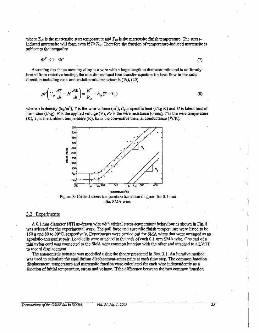
The martensite transformation kinetics is defined on a global basis using the model proposed by (13).The model parameters are quantified by a critical stress-temperature diagram (see Fig. 8) derived fromconstant temperature tensile tests carried out over a temperature range T<rMf to 1'>TAf where TMf is themartensite finish temperature (K) and TAr is the austenite finish temperature (K). The stress-inducedmartensite fraction is calculated as a function of critical stress at a specific temperature. The martensitefraction versus critical stress relationship is described using a linear function in the form of a Heavisidemodel as proposed in (16). Others have used trigonometric functions (17) or exponential functions (18) todescribe the stress-induced phase transformation.
The temperature-induced martensite fraction, <DT, is assumed to be linearly dependent on temperature
between the martensite start and finish temperatures.
Transactions ofthe CSME Ide la SCGM Vol. 31, No.1, 2007
(6)
24
where TAb is the martensite start temperature and TMfis the martensite finish temperature. The stressinduced martensite will form even if1>TM,. Therefore the fraction oftemperature-induced martensite issubject to the inequality
(7)
Assuming the shape memory alloy is a wire with a large length to diameter ratio and is uniformlyheated from resistive heating, the one-dimensional heat transfer equation for heat flow in the radialdirection including exo- and endothermic behaviour is (19), (20)
(dT dcj») E'pV C --H- =--h (T-T)
Pdt dt R th a
"(8)
where p is density (kg/m3), Vi~ the wire volume (m3
), Cpis specific heat (J/kg K) and His latent heat offormation (J/kg), E is the applied voltage (V), R" is the wire resistance (ohms), T is the wire temperature(K), Ta is the ambient temperature (K), hlh is the convective thermal conductance (WIK).
i •I •
550
500
450
400
~350
~ 300m 250•Vi '00
1SO
aMI
a..
£\loI •
Mf Ms320 340 ,.. AI 350 400
Temperature COK)
Figure 8: Critical stress-temperature transition diagram for 0.1 mmdia. SMA wire.
3.2 Experiments
A 0.1 mm diameter NiTi as-drawn wire with critical stress-temperature behaviour as shown in Fig. 8was selected for the experimental work. The pull force and austenite finish temperature were listed to be150 g and 80 to 90aC, respectively. Experiments were carried out for SMA wires that were arranged as anagonistic-antagonist pair. Load cells were attached to the ends ofeach 0.1 mm SMA wire. One end ofathin nylon cord was connected to the SMA wire commonjunction with the other end attached to a LVDTto record displacement.
The antagonistic actuator was modelled using the theory'presented in Sec. 3.1. An iterative methodwas used to calculate the eqnilibrium displacement-stress pairs at each time step. The commonjunctiondisplacement, temperature and martensite fraction were calculated for each wire independently as afunction'ofinitial temperature, stress and voltage. Ifthe difference between the two common junction
Transactions ofthe CSME fde fa SCGM Vol. 31. No. 1.2007 25
displacements exceeded a tolerance value, the initial stress would be adjusted until the predicted commonjunction displacement difference was within an acceptable error.
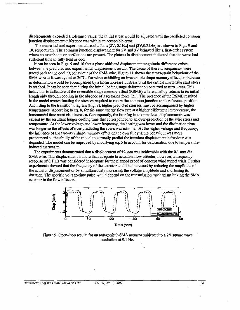
The numerical and experimental results for a [2V, O.IHz] and [3V,0.25Hz] are shown in Figs. 9 and10, respectively. The common junction displacement for 2V and 3V behaved like a first-order systemwhere no overshoots or oscillations are present. The plateau in displacement indicated that the wires hadsufficient time to fully heat or cool.
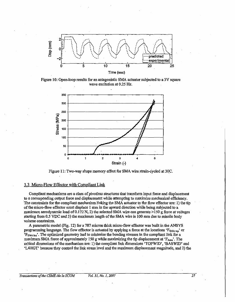
It can be seen in Figs. 9 and 10 that a phase shift and displacement magnitude difference existsbetween the predicted and experimental displacement results. The cause ofthese discrepancies weretraced back to the cooling behaviour of the SMA wire. Figure II shows the stress-strain behaviour of theSMA wire as it was cycled at 30°C. For wires exhibiting an irreversible shape memory effect, an increasein deformation would be accompanied by a linear increase in stress until the critical martensite start stressis reached. It can be seen that during the initial loading stage deformation occurred at zero stress. Thisbehaviour is mdicative ofthe reversible shape memory effect (RSME) where an alloy returns to its initiallength only through cooling in the absence ofa restoring force (21). The presence ofthe RSME resultedin the model overestimating the stresses required to return the common junction to its reference position.According to the transition diagram (Fig. 8), higher predicted stresses must be accompanied by highertemperatures. According to eq. 8, for the same energy flow rate at a higher differential temperature, theincremental time must also increase. Consequently, the time lag in the predicted displacements wascaused by the resultant longer cooling time that corresponded to an over-prediction of thewire stress andtemperature. At the lower voltage and lower frequency, the heating was lower and the dissipation timewas longer so the effects ofover predicting the stress was minimal. At the higher voltage and frequency,the influence ofthe two-way shape memory effect on the overall dynamic behaviour was morepronounced so the ability of the model to correctly predict the transient displacement behaviour wasdegraded. The model can be improved by modifying eq. 5 to account for deformation due to temperatureinduced martensite.
The experiments demonstrated that a displacement of±2 mm was achievable with the 0.1 mm dia.SMA wire. This displacement is more than adequate to actuate a flow effector, however, a frequencyresponse of0.1 Hz was considered inadequate for the planned proofofconcept wind tunnel trials. Furtherexperiments showed that the frequency ofthe actuator could be increased by reducing the amplitude ofthe actuator displacement or by simultaneously increasing the voltage amplitude and shortening itsduration. The specific voltage-time pulse would depend on the transmission mechanism linking the SMAactuator to the flow effector.
'E'2,
•,s. ,co. 0
is
0 10
-predl!:led---6
llme(soo)
Figure 9: Open-loop results for an antagonistic SMA actuator subjected to a 2V square waveexcitation at 0.1 Hz.
Transactions ofthe CSYE Ide la SCGM Vol. 31, No.1, 2007 26
2 ---, ,"'~~l
E, ,, , ,, , ,
E , , ,~ 0:
, ,, ,a. , , ,.!Il , , ,,0 , ,,
-2' ......'
0 5 10 15
-predicted- - -experimental
20 25
Time (sec)
Figure 10: Open-loop results for an antagonistic SMA actuator subjected to a 3V squarewave excitation at 0.25 Hz.
543
Strain (-)2
~
(/i.
//h
~ IIf Io
o
50
350
'iii'c..e 200III
~ 150
100
250
300
Figure II: Two-way shape memory effect for SMA wirestrain-cycled at 30C.
3.3 Micro-Flow Effector with Compliant Link
Compliant mechanisms are a class ofpivotiess structures that transform input force and displacementto a corresponding output force and displacement while attempting to maximize mechanical efficiency..The constraints for the compliant mechanism linking the SMA actuator to the flow effector are: I) the tipofthe micro-flow effector must displace I mm in the upward direction while being subjected to amaximum aerodynamic load of0.172 N, 2) the selected SMA wire can generate >150 g force at voltagesstarting from 0.5 VDC and 3) the maximum length ofthe SMA wire is 100 mm due to missile bodyvolume constraints.
A parametric model (Fig. 12) for a 787 micron thick micro-flow effector was built in the ANSYSprogramming language. The flow effector is actuated by applying a force at the locations 'FsMA to; or'FsMA bol'. The optimized geometry had to minimire the bending stresses in the compliant link for amaximum SMA force of approximately 150 g while maximizing the tip displacement at 'FA'"'' Thecritical dimensions of the mechanism are: I) the compliant link dimensions 'TOPWID', 'BASWID' and'L4HGT' because they control the link stress level and the maximum displacement magnitude, and 2) the
Transactions ofthe CSME Ide 10 SCGM Vol. 31, No.1, 2007 27
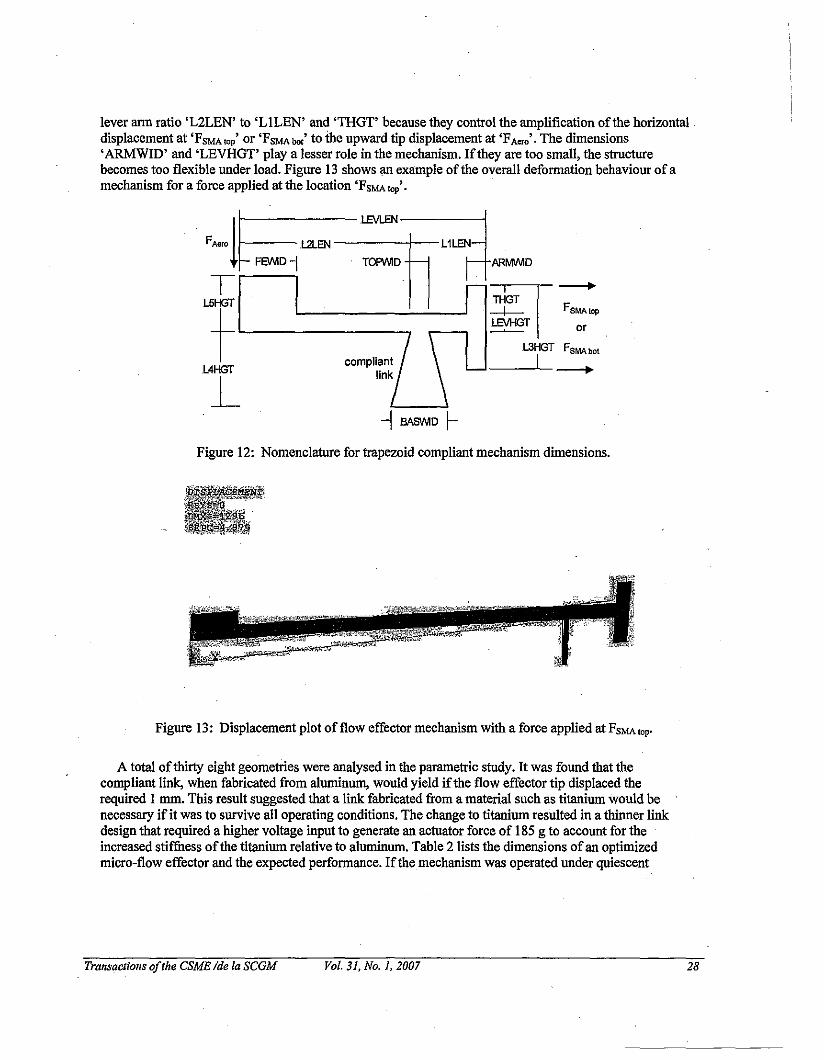
lever ann ratio 'L2LEN' to 'LILEN' and 'THGT' because they control the amplification ofthe horizontaldisplacement at 'FSMA to; or 'FsMA bot' to the npward tip displacement at 'FA',.' . The dimensions'ARMWID' and 'LEVHGT' playa lesser role in the mechanism. Ifthey are too small, the structurebecomes too flexible under load. Figure 13 shows an example of the overall deformation behaviour of amechanism for a force applied at the location 'FsMA top'.
FA,..lf---L.2LEN LEVLEN~~Dl 'h -'-rl
'- ~_---, ~T or
l3HGT FSMAbotL4HGT I __
L-I .8AS\IIi1D \-
Figure 12: Nomenclature for trapezoid compliant mechanism dimensions.
Figure 13: Displacement plot of flow effector mechanism with a force applied at FSMA top.
A total of thirty eight geometries were analysed in the parametric study. It was found that thecompliant link, when fabricated from aluminum, would yield ifthe flow effector tip displaced thereqnired I mm. This result suggested that a link fabricated from a material such as titanium would benecessary if it was to survive all operating conditions. The change to titanium resulted in a thinner linkdesign that required a higher voltage input to generate an actuator force of 185 g to account for theincreased stiffuess ofthe titanium relative to aluminum. Table 2 lists the dimensions ofan optimizedmicro-flow effector and the expected performance. Ifthe mechanism was operated under quiescent
Transactions ofthe CSME Ide 10 scaM Vol. 31, No.1, 2007 28
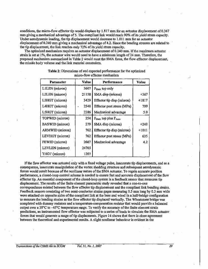
conditions, the micro-flow effector tip would displace by 1.817 mm for an actuator displacement of0.367mm giving a mechanical advantage of5. The compliant link would reach 90% of its yield stress capacity.Under aerodynamic loading, the tip displacement would decrease to 1.011 mm for an actuatordisplacement of0.240 mm giving a mechanical advantage of4.2. Since the bending stresses are related tothe tip displacement, the link reaches only 72% of its yield stress capacity.
The optimized mechanism requires an actuator displacement of0.240 mm. Ifthe maximum actuatorstrain is set at 1%, the actuator wire would need to have a minimum length of24 mm. Therefore, theproposed mechanism summarized in Table 2 would meet the SMA force, the flow effector displacement,the missile body volume and the link material constraints.
Table 2: Dimensions ofand expected performance for the optimizedmicro-flow effector mechanism
Parameter Value Performance Value
L1LEN (micron) 3607 FSMA top ouly
L2LEN (micron) 21158 SMA disp (micron) +367
L3HGT (micron) 3429 Effector tip disp (micron) +1817
L4HGT (micron) . 2540 Effector post stress (MFa) 799
L5HGT (micron) 2286 Mechanical advantage 5.0
TOPWID (micron) 254 FSMA top plus FA=
BASWID (micron) 279 SMA disp (micron) +240
ARMWID (micron) 762 Effector tip disp (micron) +lOll
LEVHGT (micron) 762 Effector post stress (MFa) 635
FEWID (micron) 2667 Mechanical advantage 4.2
LEVLEN (micron) 24765
THGT (micron) 1207
Ifthe flow effector was actuated only with a fixed voltage pulse, inaccurate tip displacements, and as aconsequence, inaccurate manipulation of the vortex shedding structure and subsequent aerodynamicforces would result because ofthe noulinear nature ofthe SMA actuator. To regain accurate positionperformance, a closed-loop control scheme is needed to ensure fast and accurate displacement ofthe floweffector tip. An essential component ofthe closed-loop system is a feedback sensor that measures tipdisplacement. The results ofthe finite element parametric study revealed that a one-to-onecorrespondence existed between the flow effector tip displacement and the compliant link bending strains.Feedback sensors consisting oftwo semi-conductor strains gages measuring 0.5 mm long by 0.3 mm widewere attached on opposite sides ofthe compliant link at the base and wired in a half-bridge configurationto measure.the bending strains as the flow effector tip displaced vertically. The Wheatstone bridge wascompleted with dummy resistors and a temperature-compensation resistor that would provide a balancedoutput over a 38°C to -45°C temperature range. To veritY the accuracy ofthe finite element strainpredictions, an instrumented flow effector was subjected to a series ofloads to simulate the SMA actuatorforces that would generate a range oftip displacments. Figure 14 shows that there is close agreementbetween the theoretical and experimental results. A slight noulinear behaviour is evident in the
Transactions ofthe CSMEliIe la SCGM Vol. 31, No.1, 2007 29
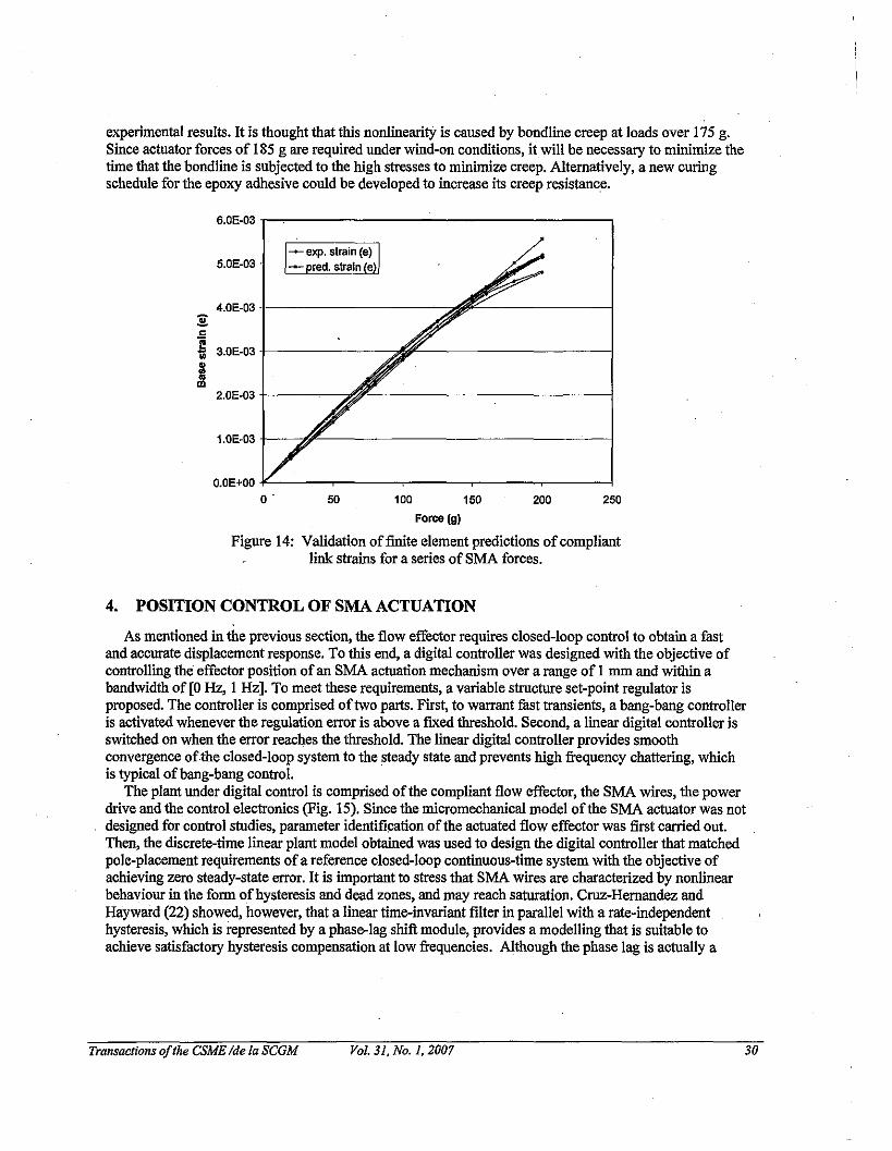
experimental results. It is thought that this nonlinearity is caused by bondline creep at loads over 175 g.Since actuator forces of 185 g are required under wind-on conditions, it will be necessary to minimize thetime that the bondline is subjected to the high stresses to minimize creep. Alternatively, a new curingschedule for the epoxy adhesive could be developed to increase its creep resistaoce.
6.OE-03
5.0E-03
4.0E-03:gc
l 3.0E-03m
=III 2.0E-03
1.0E-03
O.OE+OO -lL---~---~---,..---~---~o . 50 100 150 200 250
Force (g)
Figure 14: Validation offmite element predictions ofcompliantlink strains for a series of SMA forces.
4. POSITION CONTROL OF SMA ACTUATION
As mentioned in the previous section, the flow effector requires closed-loop control to obtain a fastand accurate displacement response. To this end, a digital controller was designed with the objective ofcontrolling the effector position of an SMA actuation mecltanism over a range of I mm and within abandwidth of [0 Hz, I Hz]. To meet these requirements, a variable structure set-point regulator isproposed. The controller is comprised oftwo parts. First, to warrant fast transients, a bang-bang controlleris activated whenever the regulation error is above a fIxed threshold. Second, a linear digital controller isswitched on when the error reaches the threshold. The linear digital controller provides smoothconvergence ofthe closed-loop system to the steady state and prevents high frequency chattering, whichis typical ofbang-bang control.
The plant under digital control is comprised ofthe compliant flow effector, the SMA wires, the powerdrive and the control electronics (Fig. 15). Since the micromechauical model of the SMA actuator was notdesigned for control studies, parameter identifIcation ofthe actuated flow effector was fIrst carried out.Then, the discrete-time linear plant model obtained was used to design the digital controller that matchedpole-placement requirements ofa reference closed-loop continuous-time system with the objective ofachieving zero steady-state error. It is importaot to stress that SMA wires are characterized by nonlinearbehaviour in the fonn ofhysteresis and dead zones, and may reach saturation. Cruz-Hernandez andHayward (22) showed, however, that a linear time-invariant f1Iter in parallel with a rate-independenthysteresis, which is represented by a phase-lag shift module, provides a modelling that is suitable toachieve satisfactory hysteresis compensation at low frequencies. Although the phase lag is actually a
Transactions oJthe CSME Ide la SCGM Vol. 31, No.1, 2007 30
function ofthe magnitude ofthe controller output, we simplify the problem by assumiog a constant phaselag characterization. First, a nonparametric identification ofthe SMA was achieved. Then, the phase bodeplot was used to devise a phasor, i.e. a phase compensator that compensates for the delay induced by thehysteresis over a specific bandwidth. The parameter identification adopted in this paper is the parametricequivalent ofthe approach proposed in (22); Experimental results show that the two-step variables~cture controller satisfies the required specifications.
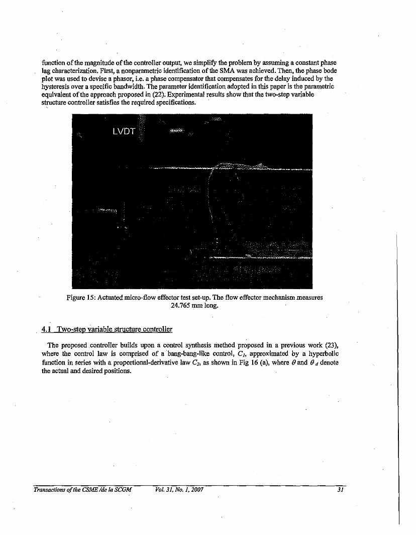
Figure 15: Actuated micro-flow effector test set-up. The flow effector mechanism measures24.765 mm long.
4. I Two-step variable structure controller
The proposed .controller builds upon a control synthesis method proposed in a previous work (23),where the control law is comprised of a ·bang-bang-like control, C], approximated by a hyperbolicfunction in series with a proportional-derivative law C2, as shown in Fig 16 (a), where (J and (J d denotethe actual and desired positions.
Transactions ofthe CSME Ide 10 SCGM Vol. 31, No.1, 2007 31
y
Flap
SMA actuator
Controle e r------lC I
----;-...,...-j-~ I~,~,e4 u I
I Iw I I
I C IL J
(a)
~---~--------------I
I+. '" (liJ IFlap error dynamic' I
IIJ
--~----------------I
+ II y w II~ SMA actuator C, I~---------------------~
(b)
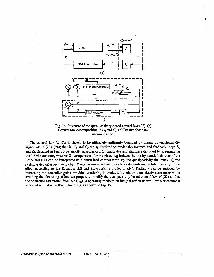
Fig. 16. Structure ofthe quasipassivity-based control law (23). (a)Control law decomposition in C1 and C2• (b) Passive feedback
decomposition.
The control law (Ch C2) is shown to be ultimately uniformly bounded by means of quasipassivityarguments in (23), (24); that is, Cl and C2 are synthesized to render the forward and feedback loops ~1
and ~2, depicted in Fig. 16(b), strictly quasipassive. ~1 passivates and stabilizes the plant by assuming anideal SMA actuator, whereas ~l compensates for the phase lag induced by the hysteretic behavior of theSMA and thus can be interpreted as a phase-lead compensator. By the quasipassivity theorem (24), thesystem trajectories approach a ball B(e",r) as t--+oo, where the radius r depends on the total memory.of thealloy, according to the Krasnoselskii and Prokrovskii's model in (24). Radius r can be reduced byincreasing the controller gains provided chattering is avoided. To obtain zero steady-state error whileavoiding the chattering effect, we propose to modify the quasipassivity-based control law of (23) so thatthe controller can switch from the (Cl ,C2) operating mode to an integral action control law that ensures aset-point regulation without chattering, as shown in Fig. 17.
TransacJions ofthe CSME Ide la SCGM Vol. 31, No.1, 2007 32
Control law
Output ofthe Ban(7-han(7 controlouter-loop
~ jf. ',1.\roll control/
d' e v SMA dm
, Digital t actuation
0-- Control -0lelse Law
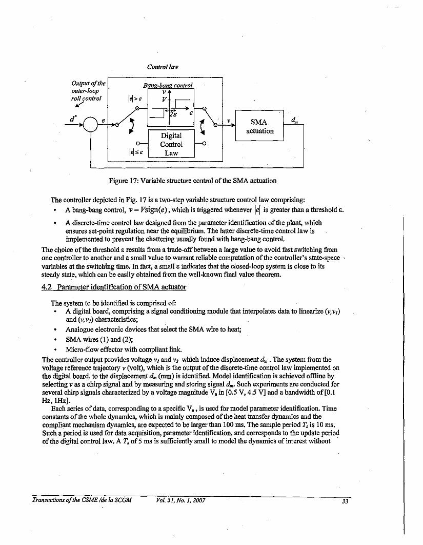
Figure 17: Variable stroctnre control oftbe SMA actuation
The controller depicted in Fig. 17 is a two-step variable strocture control law comprising:• A bang-bang control, v =Vsign(e) , which is triggered whenever lei is greater than a tbreshold E.
• A discrete-time control law designed from tbe parameter identification oftbeplant, whichensures set-point regulation near tbe equilibrium. The latter discrete-time control law isimplemented to prevent tbe chattering usually found witb bang-bang control.
The choice oftbe tbreshold E results from a trade-off between a large value to avoid fast switching fromone controller to anotber and a small value to warrant reliable computation oftbe controller's state-space .variables attbe switching time. In fact, a small E indicates that tbe closed-loop system is close to itssteady state, which can be easily obtained from tbe well-known final value tbeorem.
4.2 Parameter identification ofSMA actuator
The system to be identified is comprised of:• A digital board, comprising a sigual conditioning module tbat interpolates data to linearize (v, VI)
and (v,V2) characteristics;• Analogue electrouic devices tbat select tbe SMA wire to heat;• SMA wires (1) and (2);• Micro-flow effector witb compliant link.
The controller output provides voltage VI and V2 which induce displacement dm • The system from tbevoltage reference trajectory V (volt), which is tbe output oftbe discrete-time control law implemented ontbe digital board, to tbe displacement dm (rom) is identified. Model identification is achieved offline byselecting vasa chirp signal and by measuring and storing sigual dm' Such experiments are conducted forseveral chirp signals characterized by a voltage maguitude Va in [0.5 V, 4.5 V] and a bandwidtb of [0.1Hz,IHz].
Each series ofdata, corresponding to a specific Va , is used for model parameter identification. Timeconstants oftbe whole dynamics, which is mainly composed oftbe heat transfer dynamics and tbecompliant mechanism dynamics, are expected to be larger tban 100 ms. The sample period Ts is 10 ms.Such a period is used for data acquisition, parameter identification, and corresponds to tbe update periodoftbe digital control law. A Ts of5 ms is sufficiently small to model tbe dynamics of interest witbout .
Transactions ofthe CSME Ide la SCGM Vol. 31, No.1, 2007 33
overloading the acquisition and computing capabilities ofthe computer. The autoregressive ARX model(eq. 9) is used for parameter identification (25).
yet) + aIy(t -1) + ... + anay(t - na) =bluet - d) + ... + bnbu(t - d - nb + I) (9)
where input u and output y represent voltage v and displacement dm, respectively; na is the number ofpoles; nb-l is the number ofzeros and d is the pure delay, assumed to be an integer multiple ofT,. Theidentification is performed according to the following algorithm:
FOR each Va GET (v, dm)FOR na= 1 to 5
FOR nb= 1 to 5FORd=lt05
(a!," ..ana,b!,"..,bnh ) =ARX(v,dm,na,nb,d)END END END END
(10)
This algorithm is implemented under Matlab Identification Toolbox. Iterations performed in eq. 10 areintended to give a set ofparameters that provide the best fitting ratio. Ouly fitting ratios greater than 80 %are considered. .
4.3 Discrete-time control ofthe actuator
SMA modelDigital control lawOutput ofthe outer-loopII 1YO ';"0
1
~p(q-I)
~q-dB(q-I)
~~ 1-=1L(q-') -q A(q-')
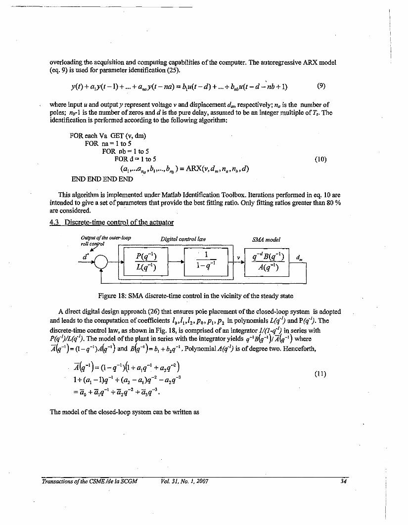
Figure 18: SMA discrete-time control in the vicinity ofthe steady state
A direct digital design approach (26) that ensures pole placement ofthe closed-loop system is adopted
and leads to the computation ofcoefficients 10,/1,lz'Po,p" pz in polynomials L(q·J) and P(q·J). The
discrete-time control law, as shown in Fig. 18, is comprised ofan integrator l/(l_q·J) in series withP(q·J)/L(q·J). The model ofthe plant in series with the integrator yields q-'B(q-')/ A(q-I) where
A(q-')= (l_q-I)A(q-') and B(q-')= bI +b2q-'. PolynomiaIA(q,J) is ofdegree two. Henceforth,
:4{q-') =(1- q-'){I +a,q-' + azq-z)
1+(aI-I)q-' +(az _a,)q-2 -azq-3- - -1 - -2 - -3=ao+ aIq + azq + a3q .
(11)
The model ofthe closed-loop system can be written as
Transactions ofthe CSME Ide la SCGM Vol. 31. No.1, 2007 34
dm
_ q-dpB7- LA+q-dBP (12)
whereA'(q-l) is a polynomial ofdegree 5. Let z, =e"T, , for 1=1,...5, the zeros ofA'. Therefore, poles
ofthe closed-loop transfer function dn/d' are equal to z" 1=1 ...5, ifthe coefficients ofL(q-I) and p(q-I)
and satisfy the following system 26 when d=1 .
0 0 0 0 0 I.,
a. a.a, 0 hi 0 0 II
,a. a,a, h2 hi 0 12
,a2 a. a2= ,a, a2 a, 0 h2 hi P. a,0 a, a2 0 0 h2
,P, a.
0 0 a, 0 0 0,
P2 as
where 0'" for i=;I,...5, are such that
A*(-l). ·-1 *-2 *-3 *-4 ·-5q =a. +a,q +a2q +a,q +a.q +asq~ -1 X-1 X-1 X-1 X-I }= q -z, q -Z2 q -z, q -z. q -zs
(13)
(14)
The identified model gives rise to undershoot that is caused by unstable zeros. It was found thatlocating dominating poles ofdn/a at $1 =$2 =-3, while $, =$4 =$S =-30, gave satisfactory responses interms ofthe rise time and the transients.
4.4 Exoerimental results
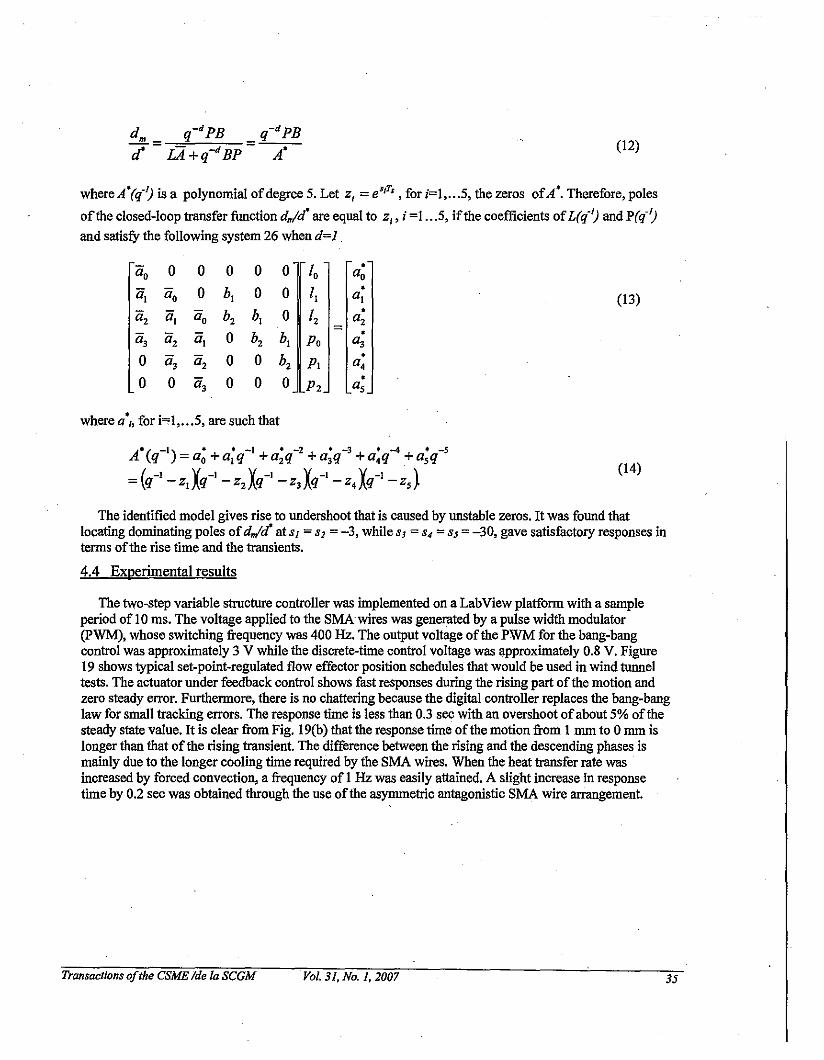
The two-step variable structure controller was implemented on a LabView platform with a sampleperiod of 10 ms. The voltage applied to the SMAwires was generated by a pulse width modulator(PWM), whose switching frequency was 400 Hz. The output voltage ofthe PWM for the bang-bangcontrol was approximately 3 V while the discrete-time control voltage was approximately 0.8 V. Figure19 shows typical set-point-regulated flow effector position schedules that would be used in wind tunneltests. The actuator under feedback control shows fast responses during the rising part ofthe motion andzero steady error. Furthermore, there is no chattering because the digital controller replaces the bang-banglaw for small tracking errors. The response time is less than 0.3 sec with an overshoot ofabout 5% ofthesteady state value. It is clear from Fig. 19(b) that the response time ofthe motion from I nun to 0 nun islonger than that of the rising transient. The difference between the rising and the descending phases ismainly due to the longer cooling time required by the SMA wires. When the heat transfer rate wasincreased by forced convection, a frequency of I Hz was easily attained. A slight increase in responsetime by 0.2 sec was obtained through the use ofthe asymmetric antagouistic SMA wire arrangement.
Transactions ofthe CSME Ide la SCGM Vol. 31. No.1. 2007 35
------ ---
"-- j;- Ij~
_._--
~~.exp ..,,. 2016
v1412
-- ._-
10
o_."------··--'l-·-···l\-·--·,,'-··--·----!I·--·-~-··--!------4
,
l 0.6
! 0.4
\0.2 t-,-,..f··-·..,.·--·---··--·~H----I-·· +-·-···-·-·--·!\\--·I
\0""-~oo ~oo
(a) (b)
Figure 19: Experimental results ofthe SMA micro-flow effector set-point regulation.(a) piecewise constant command of0.25 Hz; (b) Square wave of0.5 Hz.
5. CONCLUSIONS
A study was carried out to examine the feasibility ofemploying shape memory alloy-actuated microflow effectors to control the vortex shedding structure that produce side forces on slender body missiles.Wind tunuel tests on a missile model showed that useful side forces could be generated with static microflow effectors. Shape memory alloy (SMA)-actuated micro-flow effectors were developed to achieveactive side force control. The numerical SMA actuator displacement results compared well with theexperimental data though the presence ofthe reversible shape memory effect in the SMA wire caused thestress and temperature behaviour to be overpredicted. Matching ofthe SMA actuator to the flow effectorkinematic requirements was accomplished through a compliant mechanism. A two-step variable structurecontrol law consisting ofa bang-bang and discrete-time controller was synthesized. Closed-loop testresults showed that the proposed SMA micro-flow effector control scheme was capable ofprovidingeffective displacement control up to 1.0 Hz.
6. FUTURE WORK
Future work will focus on wind tunuel testing the missile model with a gang ofposition controlledmicro-flow effectors. A four micro-flow effector assembly covering angular positions 90, 135,225 and270 deg. is being fabricated. The flow effectors at the different angular positions will be actuated as themissile model is pitched through various angles of attack to study transient vortex shedding and side forcecontrol. Methods to increase actuator response times in the cooling phase will be investigated. Inparticular, the compliant transmission geometry will be re-examined to investigate whether a largermechanical advantage for the bottom SMA _wire can be obtained from the asymmetric moment arm tospeed the flow effector displacement response.
ACKNOWLEDGEMENTS
This work was fmanced by the Defence R&D Canada Technology Investment Fund under the project"Supersonic Missile Flight Control by Manipulation ofthe Flow Structures using Micro-ActuatedSurfaces".
Transactions of/he CSME Ide la SCGM Vol_ 31, No.1, 2007 36
7.0 REFERENCES
1. Barrett, R, (1996) "Active aeroelastic tailoring ofan adaptive Flexspar stabilator", Smart Mater.Stroct., Vol. 5, pp. 723-730.
2. Barrett, R., Stutts, J., (1997) ''Modeling, design and testing ofa barrel-launched adaptive munition",4th SPIE Symp. on Smart Stroctures andMaterials, San Diego, CA, March.
3. Patel, M., Tilmann, C.P., Ng, T.T., (2004) "Closed-Loop Missile Yaw Control via Manipulation ofForebody Flow Asymmetries", J. Spacecraft and Rockets, Vol. 41, No.3, pp. 436-443.
4. Massey, K.C., McMichael, J., Warnock, T., Hay, F., (2004) "Design and Wind"Tunnel Testing ofGuidance Pins for Supersonic Projectiles", 23rdArmy Science Conference, Orlando, FL, Paper DO01, Nov.
5. Patel, M.P., Lopera, J., Ng, T.T., (2004) "Active Boattailing and Aerodynamic Control Fins forManeuvering Weapons", 2ndAlAA Flow Control Conference, Portland, OR, Paper AIAA 2004-2696,July.
6. Corriveau, D., Hamel, N., Wong F.C., (2006) "Side Force Generation Mechanism on a Missile withNose-Mounted Micro-Structures", AIAA 2006-3000, 24th Applied Aerodynamics Conference, SanFrancisco, CA, June.
7. Chen, S., Khalid, M., (2005) ''Numerical Studies for Slender Body Flight Contrul using FlowEffectors", CFD2005, St. John's, Newfoundland, July.
8. FLUENT 6.1 User's Guide, Fluent Inc. (2003) Fluent Inc.9. Magagnato, F., (1999) "SPARC, Structure Parallel Research Code", Department ofFlnid Machinery,
University ofKarlsruhe, Karlsruhe, Germany.10. Wolfe, T.B., Faulkner, M.G., Walfaardt, J., (2005) "Development ofa shape memory alloy actuator
for a robotic eye prosthesis", Smart Mater. Stroct., Vol. 14, pp. 759-768.II. E1ahinia, M.H., Ahmadian, M., Ashrafiuon, H., (2004) "Design ofa Kahnan filter for rotary shape
memory alloy actuators", Smart Mater. Stroct., Vol. 13, pp. 691-697.12. Patoor, E., Eberhardt, A., Berveiller, M., (1988) "Thermomechanical Behaviour of Shape Memory
Alloys", Arch. Mech., Vol. 40, pp. 775-794.13. Brinson, L.C., (1993) "One-Dimensional Constitutive Behavior ofShape Memory Alloys:
Thermomechanical Derivation with Non-Constant Material Functions and Redefined MartensiteInternal Variables", J. Intel!. Mater. Syst. Struct., Vol. 4, pp. 229-242.
14. Huang, W., (1999) "Modified Shape Memory Alloy (SMA) Model for SMA Wire Base ActuatorDesign", J. Intel!. Mater. Syst. Struct., Vol. 10, pp. 221-231.
IS. Wong, F.C., Boissonneault, 0., Terriault, P., (2005) ''Hybrid Micro-Macro-mechanical ConstitutiveModel for Shape Memory Alloys", Proc. 12th SPIE Int. Symposia on Smart Structures and Materials,Paper 5761-55, March.
16. Terriault, P., Volkov, A., Trochu, F., (2003) "Chap. 16 Structure-Analytical Model" in ShapeMemory Alloys: Fundamentals, Modeling and Applications, V. Brailovski, S. Prokoshkin,P.Terriault, F. Trochu Eds., Universite du Quebec, Ecole de technologie superieure, pp. 586-615.
'17. Liang, C., Rogers, CA., (1992) "Design of Shape Memory Alloy Actuators", J. Mech. Design, Vol.114, pp. 223-230.
18. Jayender; J., Patel, R.V., Nikumb, S., Ostojic, M., (2005) ''H-infmity Loop Shaping Controller forShape Memory Alloy Actuators", Proc. 44th IEEE Can! on Decision and Control and EuropeanControl Can! 2005, Seville; Spain, December.
19. Shanin, A.R., Meckl, P.H., Jones, J.D., Thrasher, M.A., (1994) "Enchanced Cooling ofShapeMemory Alloy Wires Using Semiconductor Heat Pump Modules",J. Intel!. Mater. Syst. and Struct.,Vol. 5, pp. 95-104.
Transactions ofthe CSME Ide la SCGM Vol. 31, No.1, 2007 37
20. Bhattacharyya, A., Lagoudas, D.C., Wang, Y., Kiura, V.K., (1995) "On the role ofthermoelectricheat transfer in the design of SMA actuators: theoretical modeling and experiment", Smart Mater.Struct., Vol. 4, pp. 252-263.
21. Prokoshkin, S.D., (2003) "Chap. 4 Shape Memory Effects" in Shape Memory Alloys:Fundamentals, Modeling and Applications, V. Brailovski, S. Prokoshkin, P. Terriault, F. TrochuEds., Universite du Quebec, Ecole de technologie superieure, pp. 124-125.
22. Cruz-Hernandez, J.M. and Hayward, V., (200 I ) "Phase Control Approach to Hysteresis Reduction,"IEEE Transactions on Control Systems Technology, Vol. 9, No. I, pp. 17-26.
23. N. Lechevin, C.A. Rabbath, F.C. Wong et O. Boissonneault, "Quasipassivity-based Robust NonlinearFlap Positioning Control Using Shape Memory Alloy Micro-Actuators," Trans. ofthe CanadianSocietyfor Mechanical Engineering, Vol. 29, No.2, pp. 143-162, Invited paper, Special Edition, June2005.
24. I.G. Polushin and RJ. Marquez, "Boundedness Properties ofNonlinear Quasi-Dissipative Systems,"IEEE Trans Auto. Contr., Vol.. 49, No. 12, pp.2257-2261, 2004.
25. Ljung, L., (1999) System Identification - Theory for the User, Prentice Hall, Upper Saddle River,N.J., 2nd edition. . .
26. Astrom, K.J. and Wittenmark, B., (1990) Computer-Controlled Systems: Theory and Design, PrenticeHall, NJ.
Transactions ofthe CSME Ide ta SCGM Vol. 31, No.1, 2007 38