Embed Size (px)
Citation preview

• Sizes: 2–60” (50–1500 mm)• ASME Classes: 150–2500 • API: 2000–5000
Retainerless Design for Fugitive Emission Control
This is a condensed catalog, Code: VEL-PQCV-2006 CONDSome technical information may
have been removed. For a complete version of this catalog, please contact
Velan’s Communications Departmentand request VEL-PQCV-2006.

VELAN’S COMPANY PROFILE
HEAD OFFICE & PLANT 5
GENERAL INFORMATIONTel: (514) 748-7743 Fax: (514) [email protected]
NOTE: The material in this catalog is for general information. For specific performance data and proper material selection, consult yourVelan representative. Although every attempt has been made to ensure that the information contained in this catalog is correct, Velanreserves the right to change designs, materials or specifications without notice.
MONTREAL, CANADA 115,000 sq. ft. (10,683 m2) 2 –60” (50 –1500 mm) dual plate check valves, 3 –48” (80 –1200 mm) triple-offset butterfly valves,3⁄8 –2” (10 –50 mm) metal & resilient seated ball valves
ENGLANDVELAN VALVES LTD.Unit 1, Pinfold RoadLakeside Business ParkThurmaston Leicester LE4 8AS Tel: 44-116 269-5172Fax: 44-116 269-3695
ITALYVELAN SRLVia Delle Industrie 9/520050 Mezzago,Tel: (39) 039 624-1101Fax: (39) 039 688-3357
FRANCEVELAN S.A.S90, rue Challemel LacourF 69 367 Lyon Cedex 7 Tel: (33) 4 78 61 67 00Fax: (33) 4 78 72 12 18
PORTUGALVELAN VÁLVULASINDUSTRIAIS, LDA.Av. Ary dos Santos1679-018 FamoesTel: (351-21) 934-7800Fax: (351-21) 934-7809
TAIWANVELAN-VALVACP.O. Box 2020Taichung, TaiwanR.O.C.Tel: (04) 2792649Fax: (886) 42750855
KOREAVELAN LTD.1060-4 Shingil-DongAnsan City, Kyunggi-do 425-833Tel: (82) 31-491-2811Fax: (82) 31-491-2813
CANADAVELAN INC.HEAD OFFICE & PLANT 57007 Côte de LiesseMontreal, QC H4T 1G2Tel: (514) 748-7743Fax: (514) 748-8635
PLANT 12125 Ward AvenueMontreal, QC H4M 1T6Tel: (514) 748-7743Fax: (514) 748-8635
PLANT 2 / 7550 McArthur Ave.Montreal, QC H4T 1X8Tel: (514) 748-7743Fax: (514) 341-3032
PLANT 4 / 61010 Cowie StreetGranby, QC J2J 1E7Tel: (450) 378-2305Fax: (450) 378-6865
U.S.A.VELAN VALVECORPORATION PLANT 394 Avenue CWilliston, VT 05495-9732Tel: (802) 863-2562Fax: (802) 862-4014
ENGLANDVELAN VALVES LTD.Unit 1, Pinfold RoadLakeside Business ParkThurmaston Leicester LE4 8AS Tel: 44-116 269-5172Fax: 44-116 269-3695
GERMANYVELAN GmbH Daimlerstrasse 8 D-47877 Willich Tel: (49) 2154-4938-0Fax: (49) 2154-4938-99
MANUFACTURING LOCATIONS DISTRIBUTION CENTERS U.S.A.VELCAL537 Stone Road, Unit "A"Benicia, CA 94510Tel: (707) 745-4507Fax: (707) 745-4708
VELEAST605 Commerce Park Drive SEMarietta, GA 30060Tel: (770) 420-2010Fax: (770) 420-7063
VELNORTH94 Avenue CWilliston, VT 05495-9732Tel: (802) 651-0867Fax: (802) 865-3030
Velan has sales offices & distributors located worldwide.Visit the Velan website at www.velan.comfor an updated contact list.
© 2006 Velan Inc. All Rights Reserved.
CONTENTSCompany Profile . . . . . . . . . . . . . . . . . . . . . 2Manufacturing Program . . . . . . . . . . . . . . 3Application Industries . . . . . . . . . . . . . . . . . 4Total Quality & Process Improvement . . . 5Engineered Solutions . . . . . . . . . . . . . . . . . 6Design Features . . . . . . . . . . . . . . . . . . . 7–8Standard Materials & Specifications 9–10Wafer Type PW Valves . . . . . . . . . . . . 11–12Lug Type PL & PM Valves . . . . . . . . . 13–14Flanged Type PF & PG Valves . . . . . 15–16Special Services . . . . . . . . . . . . . . . . . . . . 17Engineering Data . . . . . . . . . . . . . . . . . . . . 18Specification of Valve Materials and Bolt Circle Diameter Data . . . . . . . . 19Installation/Service . . . . . . . . . . . . . . . . . 20How to Order . . . . . . . . . . . . . . . . . . . . . . . 21
Velan is one of the world's leading manufacturers of industrial steel valves,supplying gate, globe, check, ball, butterfly and knife gate valves for criticalapplications in the chemical, petrochemical, oil and gas, fossil and nuclear power,cogeneration, pulp and paper and cryogenic industries. See the back cover of thiscatalog for a summary of the many quality products that Velan designs andmanufactures.
Founded in 1950, Velan earned a reputation for excellence as a major supplier offorged valves for nuclear power plants and the U.S. Navy. Velan Inc. pioneered manydesigns which became industry standards, including bellows seal valves, allstainless steel knife gate valves and forged valves up to 24".
Velan valves are manufactured in 12 specialized manufacturing plants, including fivein Canada and U.S.A., four in Europe and three in Asia. We have a total of over 1,500employees, 75% of whom are located in our North American operations.
Velan’s Proquip Dual Plate Check Valves are high quality valves built for long, reliableservice life in critical services. From offshore oil platforms, to nuclear power plants,to petroleum refineries, leading construction/engineering firms and industrial enduser companies rely on Proquip Dual Plate Check Valves to keep their operationsrunning smoothly. The wide product line extends from valves for cryogenics to hightemperatures and pressures (ASME 2500), standard to specialty materials (monel,inconel, titanium) and sizes up to 60”.
2

3
MANUFACTURING PROGRAM
STANDARD PRODUCTION RANGEFor valve sizes, ASME Classes and designs not shown below, please consult Velan’s Engineering Department.
WAFER TYPE - PW
LUG TYPE - PL & PM
FLANGED TYPE - PF & PG
HUB END TYPE - PH
ASME CLASS150 300 600 900 1500 2500
2–60” 2–60” 2–60” 2–48” 2–24” 2–12”(50–1500 mm) (50–1500 mm) (50–1500 mm) (50–1200 mm) (50–600 mm) (50–300 mm)
ASME CLASS150 300 600 900 1500 2500
2–60” 2–60” 2–60” 2–48” 2–24” 2–12”(50–1500 mm) (50–1500 mm) (50–1500 mm) (50–1200 mm) (50–600 mm) (50–300 mm)
API2000 3000 5000
21/16–203/4” 21/16–203/4” 21/16–11”
ASME CLASS150 300 600 900
12–60” 12–60” 12–60” 12–48”(300–1500 mm) (300–1500 mm) (300–1500 mm) (300–1200 mm)
ASME CLASS600 900 1500 2500
2–12” 2–12” 2–12” 2–12”(50–300 mm) (50–300 mm) (50–300 mm) (50–300 mm)

4
APPLICATIONS IN MAJOR INDUSTRIES
Fossil, Nuclear & Cogeneration Power
Refining
Petrochemicals
Chemical
Pulp & Paper
Marine
Water & Wastewater
Mining
Offshore
LNG & Cryogenics
All over the world, Velan valves are used by theworld’s leading industrial companies to help keeptheir operating facilities running smoothly. In fact,Velan valves have a long history of provingthemselves in many of the industrial world’stoughest applications.

5
Our aim is to offer products and services which not only meet, but clearly exceed,
the expectations of our customers.
Through training, teamwork and performance, our employees strive to achieve
continuous improvement of all processes.
Our goal is Total Quality and On-Time Delivery; our method is Total Commitment.
A.K. Velan,Founder and C.E.O.
CERTIFICATES/APPROVALS
Velan holds all major applicable approvals, including ISO 9001:2000, PED, ASME N/NPT, TÜV, and TA-Luft.Velan’s comprehensive quality program is fully compliantwith the most stringent industry standards and has beensurveyed and audited by leading organizations, regulatory bodies, utilities and architect/engineers from around the world.
Velan’s number one priority is quality. From order entry to design engineering to the shop floor, the entirecompany is totally committed to offering products andservices that not only meet, but exceed customerexpectations. All Velan valves are designed and manu-factured with an emphasis on low emissions, safety,simple maintenance, ease of operation, and above all,long and reliable service life.
TOTAL PROCESS IMPROVEMENT
While Velan has always made quality a priority, in 1990the company adopted a formal Total Quality ManagementProgram, aimed at improving production processes andwas awarded ISO 9001 status the following year.
Today, Velan’s Total Process Improvement Programbrings together a group of industry best practices,including Lean Manufacturing and Six-Sigma, with the goal of creating a more balanced and efficientproduction system.
TOTAL PROCESS IMPROVEMENTPROGRAM:● Total Quality Management Program
(since 1990)● Lean Manufacturing● Six-Sigma
CERTIFICATIONS/APPROVALS:● ISO 9001:2000 (since1991) ● PED● ASME N and NPT (since 1970)● AD2000-Merkblatt HP 0 and A4/TRD 110● TA-Luft● QA Program fully compliant with
NCA 4000, ASME NQA-1 and 10 CFR 50 Appendix B
● Quality Programs surveyed by ASME and audited by NUPIC, Northrop GrummanNewport News, DCMA, utilities, architect/engineers and other organizations fromaround the world
TOTAL QUALITY & PROCESS IMPROVEMENT

6
Velan’s Engineering Design and Applications Group iscomprised of approximately 50 professional engineerswith extensive experience in critical applications across a broad range of industries. Equipped with advancedsoftware applications, including finite element analysis(FEA), computational fluid dynamics (CFD) and 3D solidmodeling, Velan engineers design superior quality valvesthat meet the most demanding performance require-ments. Velan’s R&D facilities, equipped with steam boilersand superheaters, flow loops and cryogenic test stands,provide the company with extensive testing capabilities.
Whether we are refining the design of our standardvalves, or engineering valves to meet the demands of aspecific application, Velan’s vast engineering resourcescan handle the task. In fact, Velan has a long history ofpartnering with major architect/engineers, electric utilitiesand other end users to develop innovative solutions fortheir valving needs.
Velan’s production machinery and equipment are speciallyengineered to meet the requirements of advanced largevalve manufacturing. This includes large CNC horizontaland vertical boring mills with tool changers, CNC lathesand CNC machining centers. Over 150 CNC machines arein operation in Velan’s North American plants.
All welding techniques employed at Velan are inaccordance with qualified welding procedures for SMAW, GTAW, GMAW, PTAW and SAW processes.
Production testing equipment is designed to safely andefficiently test high and low pressure valves in strictaccordance with industry codes and standards, as well as customer imposed criteria.
ENGINEERED SOLUTIONS
A PF24-013D10-3DB is lifted from a cryogenic testing tank.
A vertical work station with live spindle, working on a 36” Class300 Double Flanged Type PF valve body, allows for turning, mil-ling, drilling and tapping operations as applicable in one set-up.
A robotic weldingsystem applies aStellite depositonto a 10” Class150 Wafer Type PWbody seat withGMAW process.
FEA used to plot stress intensity andtotal deformation.

BODY SURFACE WITH UNINTERRUPTED GASKET SURFACEProquip dual plate check valves use an internalretention method which does not encroach on thegasket sealing surface. Other retainerless designs havean internal retention method incorporating a specialkey and retaining screws. These components encroachon the serrated sealing face area restricting the kind ofgasket that can be used. Furthermore, the screws cancorrode making maintenance difficult.
THE ADVANTAGES OF DUAL PLATE CHECK VALVES VERSUS SWING CHECK VALVES
COST SAVING DESIGNThe inherent design of the dual plate check valveresults in significantly reduced weight whencompared to conventional full-bodied swing checkvalves. As valves increase in size the dual platecheck valves can be as little as one fifth the weightof the equivalent full-bodied unit. This results insavings in initial cost, space and pipe supportelement installation.
REDUCED LINE SHOCKTo minimize or eliminate line shock, check valvesmust close as quickly as possible prior to the flowhaving an opportunity to reverse. As each of thediscs in dual plate check valves are only half the size of that of a full bodied check, they experiencereduced fluid drag and can move more quickly to the closed position. Their swing radius is one halfthat of the conventional check valves. The leadingedge distance from open to closed position is halved, in turn reducing the travel time by 50%.
The reduced weight of a dual plate valve disc versus the full bodied swing check is a major factor in minimizing slamming and water hammer.The heavier full bodied disc has greater momentumwhen swinging closed, causing it to slam into thevalve seat (in large valve sizes the disc can weigh up to a ton).
LOWER PRESSURE DROP ANDINCREASED Cv FOR VALVES 24”AND LARGERThe two factors that affect pressure drop across any valve are:
1) The unobstructed flow area.
2) The energy required to maintain the valve in the open position. Specifically, full-bodied swingcheck valves have a disc which is hinged at thetop with gravity working to keep it in the closedposition. Flow must provide sufficient energy toovercome this force of gravity and lift the disc.This energy requirement increases dramaticallyin larger sizes.
Dual plate check valves are designed such that the discs are hinged at their sides like a door,eliminating the effect of gravity. Consequently, very little energy is needed to open the valve and maintain this position, resulting in lowerenergy costs.
7
SUPERIOR PERFORMANCE OF THE
LAPPED BODY & DISC SEATS The heart of each valve is the seat/seal interface. Proquip valves are manufactured using the mostupdated machining methods and equipment to achievemaximum flatness with a fine lapped finish. The endresult is valves that easily meet and exceed testrequirements of API 598 for metal-seated check valves.
INTRINSICALLYFIRE SAFE With no drilling throughthe body wall, the Proquipdual plate check valve isintrinsically fire safe.
Wafer Type - PW Dual Plate CheckValve shown

8
PROQUIP DUAL PLATE CHECK VALVE DESIGN
SHOCK BUMPERS The Proquip design utilizesheavy duty “shock bumpers“on the back of each disc.These bumpers meet when thevalve is in the full openposition thus preventing thediscs from striking the stoppin. This arrangement reducesthe shock force on the hinges,ensuring internal componentshave an extended cycle lifewith minimal wear under themost severe serviceconditions.
SUPERIOR HINGE DESIGNIn order to eliminate seat wear during the opening cycle,all dual plate check valves incorporate clearance betweenthe hinge pin and holders, or hinge pin and disc bore.This clearance allows the disc assembly to lift off theseat prior to disc rotation preventing the heel of eachdisc from scraping across the body seat. Conventionaldesigns have an oversize bore in the discs or bearings,allowing constant side to side movement of discs andincreased chance of premature failure.
The patented Proquip hinge pin slot allows movement in only one axis preventing premature wear. The discs,therefore, last longer and the useful life of the valve isextended.
The Proquip dual platecheck valve’s body isessentially a short, heavywall cylinder with no holesthrough the body wall.There is no need forretainers and leakage tothe outside is impossible.
RETAINERLESS BODY DESIGN
Shock bumper
Conventional dual plate check valves requireholes through the body wall to facilitate theinstallation of the hinge and stop pins. Theseholes are sealed by threaded pipe plugs calledretainers. After being in service for a period oftime, these plugs often leak due to temperaturecycling, vibration and other causes.
Conventional dual platecheck valve design with
pin retainers.
Pin retainer
HIGH TORSION SPRING For potentially severe applications, a high torsionspring ensures the valve closes as quickly as possible.
Proquip patented design: Slot permits movementin direction of flow only (no rattling).

9
BODY AND ALL PARTS
1
5
5
9
2
3
4*8
7
10
10
6
11
9
11
Type PW Wafer dual plate check valve design shown.
*Disc seat visible on other side of disc
PART
1 Body 7 Hinge pin(1)
2 Body seat 8 Stop pin(1)
3 Disc(1) 9 Retainer pin(1)
4 Disc seat 10 Lock washer(1)
5 Holder(1) 11 Lock pin(1)
6 Spring(1)
(1) Spare part components as required.

19 10
6
8
5
4
3
2
7
10
11
ITEM APPLICABLE SPECIFICATION
Wall thickness and general valve design API 594
Pressure-temperature rating ASME B16.34
Face-to-face dimensions API 594
Flange design2–24” (50–600 mm) ASME B16.5
26” (650 mm) B16.47 Series A
Testing API 598
Materials ASTM
10
STANDARD MATERIALS & SPECIFICATIONS
CARBON STEEL (1)
FIGURE NO. ➀ BODY ➂ DISC ➁ BODY SEAT ➃ DISC SEAT ➅ SPRING WETTED PARTS (2)
_ _ _ _ -_ 02D10-3DB A216 Gr. WCB A351 Gr. CF8M Same as Body Same as Disc Inconel X-750 316 SS_ _ _ _ -_ 02D13-3DB A216 Gr. WCB A351 Gr. CF8M Viton A Same as Disc Inconel X-750 316 SS_ _ _ _ -_ 02D19-3DB A216 Gr. WCB A351 Gr. CF8M Stellite overlay Same as Disc Inconel X-750 316 SS_ _ _ _ -_ 02E18-3EB A216 Gr. WCB A217 Gr. CA15 410 SS overlay Same as Disc Inconel X-750 410 SS (3)
_ _ _ _ -_ 02E19-3EB A216 Gr. WCB A217 Gr. CA15 Stellite overlay Same as Disc Inconel X-750 410 SS (3)
FIGURE NO. ➀ BODY ➂ DISC ➁ BODY SEAT ➃ DISC SEAT ➅ SPRING WETTED PARTS (2)
_ _ _ _ -_ 31D10-3DB A352 Gr. LCC A351 Gr. CF8M Same as Body Same as Disc Inconel X-750 316 SS_ _ _ _ -_ 31D11-3DB A352 Gr. LCC A351 Gr. CF8M Buna-N Same as Disc Inconel X-750 316 SS_ _ _ _ -_ 31D19-3DB A352 Gr. LCC A351 Gr. CF8M Stellite overlay Same as Disc Inconel X-750 316 SS
LOW TEMPERATURE CARBON STEEL
FIGURE NO. ➀ BODY ➂ DISC ➁ BODY SEAT ➃ DISC SEAT ➅ SPRING WETTED PARTS (2)
_ _ _ _ -_ 13D10-3DB A351 Gr. CF8M A351 Gr. CF8M Same as Body Same as Disc Inconel X-750 316 SS_ _ _ _ -_ 13D13-3DB A351 Gr. CF8M A351 Gr. CF8M Viton A Same as Disc Inconel X-750 316 SS_ _ _ _ -_ 13D19-3DB A351 Gr. CF8M A351 Gr. CF8M Stellite overlay Same as Disc Inconel X-750 316 SS
STAINLESS STEEL
DESIGN SPECIFICATIONS
(1) For alternative materials, please consult the HTO table on Page 25.(2) Wetted parts comprise the following components: Holders, Hinge Pin, Stop Pin and Retainer Pins (part numbers 5, 7, 8, and 9).(3) The Lock Washer and Lock Pin (part numbers 10 and 11) remain as 316 SS.

11
DIMENSIONS & WEIGHTS
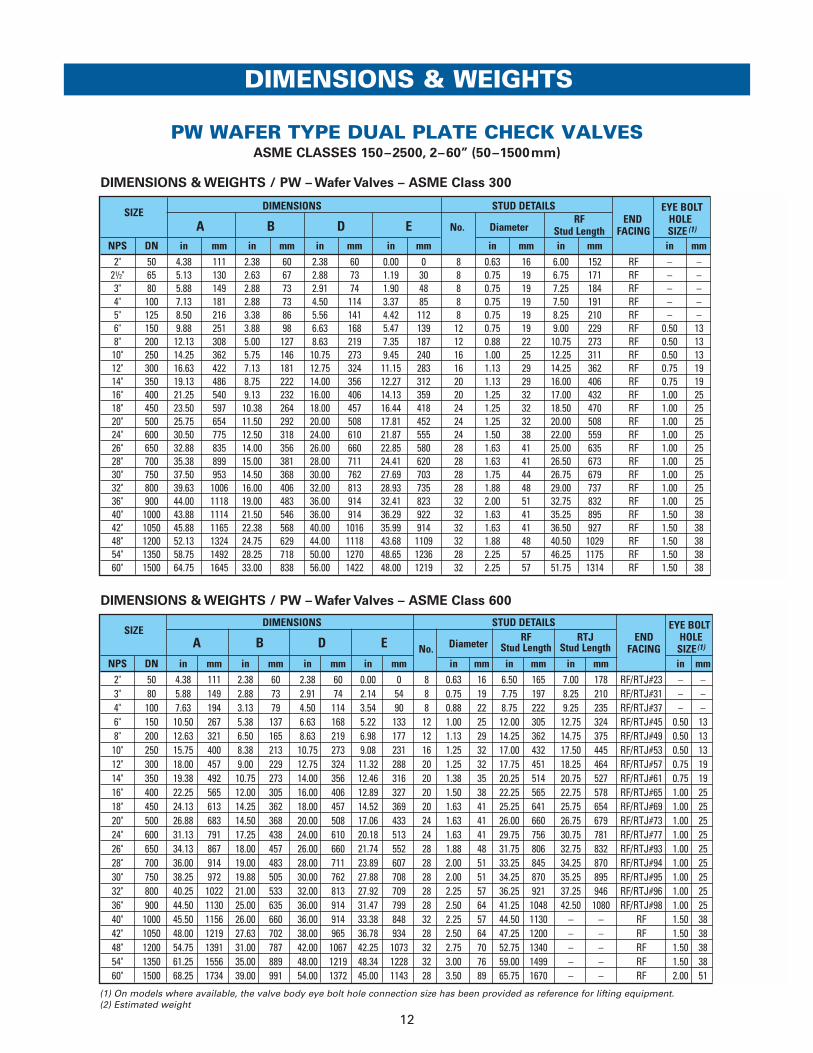
PW WAFER TYPE DUAL PLATE CHECK VALVES ASME CLASSES 150–2500, 2–60” (50–1500mm)
SIZEDIMENSIONS STUD DETAILS EYE BOLT
A B D E No. DiameterRF END HOLE
APPROXIMATE
Stud Length FACING SIZE (1)WEIGHT
NPS DN in mm in mm in mm in mm in mm in mm in mm lbs kg
2" 50 4.13 105 2.38 60 2.38 60 0.00 0 4 0.63 16 5.75 146 RF – – 6 321/2" 65 4.88 124 2.63 67 2.88 73 1.05 27 4 0.63 16 6.25 159 RF – – 11 53" 80 5.38 137 2.88 73 2.88 73 1.68 43 4 0.63 16 6.75 171 RF – – 11 54" 100 6.88 175 2.88 73 4.50 114 3.37 85 8 0.63 16 6.75 171 RF – – 18 85" 125 7.75 197 3.38 86 5.56 141 4.42 112 8 0.75 19 7.50 191 RF – – 28 136" 150 8.75 222 3.88 98 6.63 168 5.62 143 8 0.75 19 8.00 203 RF 0.50 13 31 148" 200 11.00 279 5.00 127 8.63 219 7.35 187 8 0.75 19 9.50 241 RF 0.50 13 57 2610" 250 13.38 340 5.75 146 10.75 273 9.45 240 12 0.88 22 10.50 267 RF 0.50 13 98 4512" 300 16.13 410 7.13 181 12.75 324 11.15 283 12 0.88 22 12.25 311 RF 0.75 19 140 6414" 350 17.75 451 7.25 184 14.00 356 12.23 311 12 1.00 25 12.75 324 RF 0.75 19 170 7716" 400 20.25 514 7.50 191 16.00 406 13.99 355 16 1.13 29 13.25 337 RF 1.00 25 230 10418" 450 21.63 549 8.00 203 18.00 457 15.95 405 16 1.13 29 14.25 362 RF 1.00 25 270 12320" 500 23.88 606 8.63 219 20.00 508 17.78 452 20 1.25 32 15.25 387 RF 1.00 25 360 16324" 600 28.25 718 8.75 222 24.00 610 21.29 541 20 1.25 32 16.00 406 RF 1.00 25 480 21826" 650 30.50 775 14.00 356 26.00 660 21.96 558 24 1.25 32 23.25 591 RF 1.00 25 1000 45428" 700 32.75 832 15.00 381 28.00 711 22.06 560 28 1.25 32 24.50 622 RF 1.00 25 1200 54430" 750 34.75 883 12.00 305 30.00 762 27.80 706 28 1.25 32 21.75 552 RF 1.00 25 1000 45432" 800 37.00 940 14.00 356 32.00 813 29.25 743 28 1.50 38 24.75 629 RF 1.00 25 1400 63536" 900 41.25 1048 14.50 368 36.00 914 33.40 848 32 1.50 38 26.00 660 RF 1.00 25 1750 79440" 1000 45.75 1162 17.00 432 40.00 1016 37.56 954 36 1.50 38 28.50 724 RF 1.50 38 2600 117942" 1050 48.00 1219 17.00 432 42.00 1067 39.20 996 36 1.50 38 29.00 737 RF 1.50 38 2850 129348" 1200 54.50 1384 20.63 524 48.00 1219 43.06 1094 44 1.50 38 31.00 787 RF 1.50 38 4400 199654" 1350 61.00 1549 23.25 591 54.00 1372 50.44 1281 44 1.75 44 35.75 908 RF 1.50 38 5500(2) 2495(2)
60" 1500 67.50 1715 26.00 660 60.00 1524 55.68 1414 52 1.75 44 38.75 984 RF 1.50 38 7200(2) 3266(2)
DIMENSIONS & WEIGHTS / PW – Wafer Type – ASME Class 150
(1) On models where available, the valve body eye bolt hole connection size has been provided as reference for lifting equipment. (2) Estimated weight
12
SIZEDIMENSIONS STUD DETAILS EYE BOLT
A B D E No. DiameterRF RTJ END HOLE
APPROXIMATE
Stud Length Stud Length FACING SIZE(1)WEIGHT
NPS DN in mm in mm in mm in mm in mm in mm in mm in mm lbs kg2" 50 4.38 111 2.38 60 2.38 60 0.00 0 8 0.63 16 6.50 165 7.00 178 RF/RTJ#23 – – 6.5 33" 80 5.88 149 2.88 73 2.91 74 2.14 54 8 0.75 19 7.75 197 8.25 210 RF/RTJ#31 – – 13 64" 100 7.63 194 3.13 79 4.50 114 3.54 90 8 0.88 22 8.75 222 9.25 235 RF/RTJ#37 – – 24 116" 150 10.50 267 5.38 137 6.63 168 5.22 133 12 1.00 25 12.00 305 12.75 324 RF/RTJ#45 0.50 13 69 318" 200 12.63 321 6.50 165 8.63 219 6.98 177 12 1.13 29 14.25 362 14.75 375 RF/RTJ#49 0.50 13 116 5310" 250 15.75 400 8.38 213 10.75 273 9.08 231 16 1.25 32 17.00 432 17.50 445 RF/RTJ#53 0.50 13 210 9512" 300 18.00 457 9.00 229 12.75 324 11.32 288 20 1.25 32 17.75 451 18.25 464 RF/RTJ#57 0.75 19 300 13614" 350 19.38 492 10.75 273 14.00 356 12.46 316 20 1.38 35 20.25 514 20.75 527 RF/RTJ#61 0.75 19 430 19516" 400 22.25 565 12.00 305 16.00 406 12.89 327 20 1.50 38 22.25 565 22.75 578 RF/RTJ#65 1.00 25 650 29518" 450 24.13 613 14.25 362 18.00 457 14.52 369 20 1.63 41 25.25 641 25.75 654 RF/RTJ#69 1.00 25 850 38620" 500 26.88 683 14.50 368 20.00 508 17.06 433 24 1.63 41 26.00 660 26.75 679 RF/RTJ#73 1.00 25 1125 51024" 600 31.13 791 17.25 438 24.00 610 20.18 513 24 1.63 41 29.75 756 30.75 781 RF/RTJ#77 1.00 25 1750 79426" 650 34.13 867 18.00 457 26.00 660 21.74 552 28 1.88 48 31.75 806 32.75 832 RF/RTJ#93 1.00 25 1950 88528" 700 36.00 914 19.00 483 28.00 711 23.89 607 28 2.00 51 33.25 845 34.25 870 RF/RTJ#94 1.00 25 2300 104330" 750 38.25 972 19.88 505 30.00 762 27.88 708 28 2.00 51 34.25 870 35.25 895 RF/RTJ#95 1.00 25 2850 129332" 800 40.25 1022 21.00 533 32.00 813 27.92 709 28 2.25 57 36.25 921 37.25 946 RF/RTJ#96 1.00 25 3200 145236" 900 44.50 1130 25.00 635 36.00 914 31.47 799 28 2.50 64 41.25 1048 42.50 1080 RF/RTJ#98 1.00 25 4700 213240" 1000 45.50 1156 26.00 660 36.00 914 33.38 848 32 2.25 57 44.50 1130 – – RF 1.50 38 5200 235942" 1050 48.00 1219 27.63 702 38.00 965 36.78 934 28 2.50 64 47.25 1200 – – RF 1.50 38 6000 272248" 1200 54.75 1391 31.00 787 42.00 1067 42.25 1073 32 2.75 70 52.75 1340 – – RF 1.50 38 8600 390154" 1350 61.25 1556 35.00 889 48.00 1219 48.34 1228 32 3.00 76 59.00 1499 – – RF 1.50 38 12100(2) 5489(2)
60" 1500 68.25 1734 39.00 991 54.00 1372 45.00 1143 28 3.50 89 65.75 1670 – – RF 2.00 51 17000(2) 7711(2)
DIMENSIONS & WEIGHTS / PW – Wafer Valves – ASME Class 600
DIMENSIONS & WEIGHTS
PW WAFER TYPE DUAL PLATE CHECK VALVES ASME CLASSES 150–2500, 2–60” (50–1500mm)
DIMENSIONS & WEIGHTS / PW – Wafer Valves – ASME Class 300
SIZEDIMENSIONS STUD DETAILS EYE BOLT
A B D E No. DiameterRF END HOLE
APPROXIMATE
Stud Length FACING SIZE (1)WEIGHT
NPS DN in mm in mm in mm in mm in mm in mm in mm lbs kg2" 50 4.38 111 2.38 60 2.38 60 0.00 0 8 0.63 16 6.00 152 RF – – 6.5 3
21/2" 65 5.13 130 2.63 67 2.88 73 1.19 30 8 0.75 19 6.75 171 RF – – 13 63" 80 5.88 149 2.88 73 2.91 74 1.90 48 8 0.75 19 7.25 184 RF – – 13 64" 100 7.13 181 2.88 73 4.50 114 3.37 85 8 0.75 19 7.50 191 RF – – 18 85" 125 8.50 216 3.38 86 5.56 141 4.42 112 8 0.75 19 8.25 210 RF – – 28 136" 150 9.88 251 3.88 98 6.63 168 5.47 139 12 0.75 19 9.00 229 RF 0.50 13 40 188" 200 12.13 308 5.00 127 8.63 219 7.35 187 12 0.88 22 10.75 273 RF 0.50 13 68 3110" 250 14.25 362 5.75 146 10.75 273 9.45 240 16 1.00 25 12.25 311 RF 0.50 13 110 5012" 300 16.63 422 7.13 181 12.75 324 11.15 283 16 1.13 29 14.25 362 RF 0.75 19 170 7714" 350 19.13 486 8.75 222 14.00 356 12.27 312 20 1.13 29 16.00 406 RF 0.75 19 290 13216" 400 21.25 540 9.13 232 16.00 406 14.13 359 20 1.25 32 17.00 432 RF 1.00 25 400 18118" 450 23.50 597 10.38 264 18.00 457 16.44 418 24 1.25 32 18.50 470 RF 1.00 25 520 23620" 500 25.75 654 11.50 292 20.00 508 17.81 452 24 1.25 32 20.00 508 RF 1.00 25 700 31824" 600 30.50 775 12.50 318 24.00 610 21.87 555 24 1.50 38 22.00 559 RF 1.00 25 1050 47626" 650 32.88 835 14.00 356 26.00 660 22.85 580 28 1.63 41 25.00 635 RF 1.00 25 1250 56728" 700 35.38 899 15.00 381 28.00 711 24.41 620 28 1.63 41 26.50 673 RF 1.00 25 1500 68030" 750 37.50 953 14.50 368 30.00 762 27.69 703 28 1.75 44 26.75 679 RF 1.00 25 1650 74832" 800 39.63 1006 16.00 406 32.00 813 28.93 735 28 1.88 48 29.00 737 RF 1.00 25 2000 90736" 900 44.00 1118 19.00 483 36.00 914 32.41 823 32 2.00 51 32.75 832 RF 1.00 25 2700 122540" 1000 43.88 1114 21.50 546 36.00 914 36.29 922 32 1.63 41 35.25 895 RF 1.50 38 3400 154242" 1050 45.88 1165 22.38 568 40.00 1016 35.99 914 32 1.63 41 36.50 927 RF 1.50 38 4200 190548" 1200 52.13 1324 24.75 629 44.00 1118 43.68 1109 32 1.88 48 40.50 1029 RF 1.50 38 7350 333454" 1350 58.75 1492 28.25 718 50.00 1270 48.65 1236 28 2.25 57 46.25 1175 RF 1.50 38 7300(2) 3311(2)
60" 1500 64.75 1645 33.00 838 56.00 1422 48.00 1219 32 2.25 57 51.75 1314 RF 1.50 38 10000(2) 4536(2)
(1) On models where available, the valve body eye bolt hole connection size has been provided as reference for lifting equipment. (2) Estimated weight

13
DIMENSIONS & WEIGHTS / PL & PM – Solid Lug Type – ASME Class 150
(1) On models where available, the valve body eye bolt hole connection size has been provided as reference for lifting equipment. (2) Estimated weight
SIZEDIMENSIONS STUD DETAILS EYE BOLT
A B D E No. DiameterRF END HOLE
APPROXIMATE
Stud Length FACING SIZE (1) WEIGHT
NPS DN in mm in mm in mm in mm in mm in mm in mm lbs kg
2" 50 6.00 152 2.38 60 2.38 60 0.00 0 4 0.63 16 2.75 70 RF – – 9 421/2" 65 7.00 178 2.63 67 2.88 73 1.05 27 4 0.63 16 2.75 70 RF – – 24 113" 80 7.50 191 2.88 73 2.88 73 1.68 43 4 0.63 16 3.00 76 RF – – 18 84" 100 9.00 229 2.88 73 4.50 114 3.37 85 8 0.63 16 3.00 76 RF – – 33 155" 125 10.00 254 3.38 86 5.56 141 4.42 112 8 0.75 19 3.25 83 RF – – 53 246" 150 11.00 279 3.88 98 6.63 168 5.62 143 8 0.75 19 3.25 83 RF 0.50 13 53 248" 200 13.50 343 5.00 127 8.63 219 7.35 187 8 0.75 19 3.50 89 RF 0.50 13 130 5910" 250 16.00 406 5.75 146 10.75 273 9.45 240 12 0.88 22 3.75 95 RF 0.50 13 216 9812" 300 19.00 483 7.13 181 12.75 324 11.15 283 12 0.88 22 3.75 95 RF 0.75 19 270 12314" 350 21.00 533 7.25 184 14.00 356 12.23 311 12 1.00 25 4.25 108 RF 0.75 19 330 15016" 400 23.50 597 1.50 38 16.00 406 13.99 355 16 1.00 25 4.25 108 RF 1.00 25 420 19118" 450 25.00 635 8.00 203 18.00 457 15.95 405 16 1.13 29 4.75 121 RF 1.00 25 500 22720" 500 27.50 699 8.63 219 20.00 508 17.78 452 20 1.13 29 5.00 127 RF 1.00 25 650 29524" 600 32.00 813 8.75 222 24.00 610 21.29 541 20 1.25 32 5.50 140 RF 1.00 25 850 38626" 650 34.25 870 14.00 356 26.00 660 21.96 558 24 1.25 32 6.50 165 RF 1.00 25 1600 72628" 700 36.50 927 15.00 381 28.00 711 22.06 560 28 1.25 32 6.50 165 RF 1.00 25 1900 86230" 750 38.75 984 12.00 305 30.00 762 27.80 706 28 1.25 32 6.75 171 RF 1.00 25 1700 77132" 800 41.75 1060 14.00 356 32.00 813 29.25 743 28 1.50 38 7.50 191 RF 1.00 25 2400 108936" 900 46.00 1168 14.50 368 36.00 914 33.40 848 32 1.50 38 8.00 203 RF 1.00 25 2800 127040" 1000 50.75 1289 17.00 432 40.00 1016 37.56 954 36 1.50 38 8.00 203 RF 1.50 38 4100 186042" 1050 53.00 1346 17.00 432 42.00 1067 39.20 996 36 1.50 38 8.25 210 RF 1.50 38 4400 199648" 1200 59.50 1511 20.63 524 48.00 1219 43.06 1094 44 1.50 38 8.75 222 RF 1.50 38 6600 299454" 1350 66.25 1683 23.25 591 54.00 1372 50.44 1281 44 1.75 44 9.75 248 RF 1.50 38 8300(2) 3765(2)
60" 1500 73.00 1854 26.00 660 60.00 1524 55.68 1414 52 1.75 44 10.25 260 RF 2.00 51 10700(2) 4853(2)
DIMENSIONS & WEIGHTS
PL & PM SOLID LUG TYPE DUAL PLATE CHECK VALVES ASME CLASSES 150–900, 2–60” (50–1500mm)

14
SIZEDIMENSIONS STUD DETAILS EYE BOLT
A B D E No. Diameter RF RTJ END HOLEAPPROXIMATE
Stud Length Stud Length FACING SIZE (1) WEIGHT
NPS DN in mm in mm in mm in mm in mm in mm in mm in mm lbs kg2" 50 6.50 165 2.38 60 2.38 60 0.00 0 8 0.63 16 3.25 83 3.75 95 RF/RTJ#23 – – 18 83" 80 8.25 210 2.88 73 2.91 74 2.14 54 8 0.75 19 3.75 95 4.25 108 RF/RTJ#31 – – 33 154" 100 10.75 273 3.13 79 4.50 114 3.54 90 8 0.88 22 4.25 108 4.75 121 RF/RTJ#37 – – 86 396" 150 14.00 356 5.38 137 6.63 168 5.22 133 12 1.00 25 5.00 127 5.50 140 RF/RTJ#45 0.50 13 172 788" 200 16.50 419 6.50 165 8.63 219 6.98 177 12 1.13 29 5.75 146 6.00 152 RF/RTJ#49 0.50 13 312 14210" 250 20.00 508 8.38 213 10.75 273 9.08 231 16 1.25 32 6.25 159 6.75 171 RF/RTJ#53 0.50 13 515 23412" 300 22.00 559 9.00 229 12.75 324 11.32 288 20 1.25 32 6.50 165 6.75 171 RF/RTJ#57 0.75 19 550 25014" 350 23.75 603 10.75 273 14.00 356 12.46 316 20 1.38 35 6.75 171 7.25 184 RF/RTJ#61 0.75 19 800 36316" 400 27.00 686 12.00 305 16.00 406 12.89 327 20 1.50 38 7.50 191 7.75 197 RF/RTJ#65 1.00 25 1150 52218" 450 29.25 743 14.25 362 18.00 457 14.52 369 20 1.63 41 8.00 203 8.50 216 RF/RTJ#69 1.00 25 1550 70320" 500 32.00 813 14.50 368 20.00 508 17.06 433 24 1.63 41 8.25 210 9.00 229 RF/RTJ#73 1.00 25 1900 86224" 600 37.00 940 17.50 445 24.00 610 20.18 513 24 1.63 41 8.75 222 9.50 241 RF/RTJ#77 1.00 25 3000 136126" 650 40.00 1016 18.00 457 26.00 660 21.74 552 28 1.88 48 9.50 241 10.50 267 RF/RTJ#93 1.00 25 3400 154228" 700 42.25 1073 19.00 483 28.00 711 23.89 607 28 2.00 51 10.00 254 11.00 279 RF/RTJ#94 1.00 25 4000 181430" 750 44.50 1130 19.88 505 30.00 762 27.88 708 28 2.00 51 10.25 260 11.25 286 RF/RTJ#95 1.00 25 4700 213232" 800 47.00 1194 21.00 533 32.00 813 27.92 709 28 2.25 57 11.00 279 12.00 305 RF/RTJ#96 1.00 25 5400 244936" 900 51.75 1314 25.00 635 36.00 914 31.47 799 28 2.50 64 11.75 298 13.00 330 RF/RTJ#98 1.00 25 7800 353840" 1000 52.00 1321 26.00 660 36.00 914 33.38 848 32 2.25 57 12.50 318 – – RF 1.50 38 8100 367442" 1050 55.25 1403 27.63 702 38.00 965 36.78 934 28 2.50 64 13.50 343 – – RF 1.50 38 9600 435548" 1200 62.75 1594 31.00 787 42.00 1067 42.25 1073 32 2.75 70 15.00 381 – – RF 1.50 38 13700 621454" 1350 70.00 1778 35.00 889 48.00 1219 48.34 1228 32 3.00 76 16.50 419 – – RF 2.00 51 19200(2) 8709(2)
60" 1500 78.50 1994 39.00 991 54.00 1372 45.00 1143 28 3.50 89 18.75 476 – – RF 2.50 64 29200(2) 13245(2)
DIMENSIONS & WEIGHTS / PL & PM – Solid Lug Type – ASME Class 600
DIMENSIONS & WEIGHTS
PL & PM SOLID LUG TYPE DUAL PLATE CHECK VALVES ASME CLASSES 150–900, 2–60” (50–1500mm)
SIZEDIMENSIONS STUD DETAILS EYE BOLT
A B D E No. DiameterRF END HOLE
APPROXIMATE
Stud Length FACING SIZE (1)WEIGHT
NPS DN in mm in mm in mm in mm in mm in mm in mm lbs kg
2" 50 6.50 165 2.38 60 2.38 60 0.00 0 8 0.63 16 2.75 70 RF – – 18 821/2" 65 7.50 191 2.63 67 2.88 73 1.19 30 8 0.75 19 3.25 83 RF – – 26 123" 80 8.25 210 2.88 73 2.91 74 1.90 48 8 0.75 19 3.50 89 RF – – 33 154" 100 10.00 254 2.88 73 4.50 114 3.37 85 8 0.75 19 3.50 89 RF – – 55 255" 125 11.00 279 3.38 86 5.56 141 4.42 112 8 0.75 19 3.75 95 RF – – 70 326" 150 12.50 318 3.88 98 6.63 168 5.47 139 12 0.75 19 3.75 95 RF 0.50 13 99 458" 200 15.00 381 5.00 127 8.63 219 7.35 187 12 0.88 22 4.25 108 RF 0.50 13 143 6510" 250 17.50 445 5.75 146 10.75 273 9.45 240 16 1.00 25 4.75 121 RF 0.50 13 233 10612" 300 20.50 521 7.13 181 12.75 324 11.15 283 16 1.13 29 5.25 133 RF 0.75 19 350 15914" 350 23.00 584 8.75 222 14.00 356 12.27 312 20 1.13 29 5.25 133 RF 0.75 19 550 25016" 400 25.50 648 9.13 232 16.00 406 14.13 359 20 1.25 32 5.75 146 RF 1.00 25 750 34018" 450 28.00 711 10.38 264 18.00 457 16.44 418 24 1.25 32 6.00 152 RF 1.00 25 950 43120" 500 30.50 775 11.50 292 20.00 508 17.81 452 24 1.25 32 6.00 152 RF 1.00 25 1250 56724" 600 36.00 914 12.50 318 24.00 610 21.87 555 24 1.50 38 7.00 178 RF 1.00 25 1850 83926" 650 38.25 972 14.00 356 26.00 660 22.85 580 28 1.63 41 7.75 197 RF 1.00 25 2200 99828" 700 40.75 1035 15.00 381 28.00 711 24.41 620 28 1.63 41 8.25 210 RF 1.00 25 2700 122530" 750 43.00 1092 14.50 368 30.00 762 27.69 703 28 1.75 44 8.75 222 RF 1.00 25 2800 127032" 800 45.25 1149 16.00 406 32.00 813 28.93 735 28 1.88 48 9.25 235 RF 1.00 25 3400 154236" 900 50.00 1270 19.00 483 36.00 914 32.41 823 32 2.00 51 9.75 248 RF 1.00 25 4600 208740" 1000 48.75 1238 21.50 546 36.00 914 36.29 922 32 1.63 41 9.25 235 RF 1.50 38 5100 231342" 1050 50.75 1289 22.38 568 40.00 1016 35.99 914 32 1.63 41 9.50 241 RF 1.50 38 6100 276748" 1200 57.75 1467 24.75 629 44.00 1118 43.68 1109 32 1.88 48 10.50 267 RF 1.50 38 10000 453654" 1350 65.25 1657 28.25 718 50.00 1270 48.65 1236 28 2.25 57 12.25 311 RF 1.50 38 11300 512660" 1500 71.25 1810 33.00 838 56.00 1422 48.00 1219 32 2.25 57 12.75 324 RF 2.00 51 14800 6713
DIMENSIONS & WEIGHTS / PL & PM – Solid Lug Type – ASME Class 300
(1) On models where available, the valve body eye bolt hole connection size has been provided as reference for lifting equipment. (2) Estimated weight

15
DIMENSIONS & WEIGHTS / PF & PG – Double Flanged Type – ASME Class 150
SIZEDIMENSIONS STUD DETAILS
A B D ENo.(1) Diameter
RF END APPROXIMATE
Stud Length FACINGWEIGHT
NPS DN in mm in mm in mm in mm in mm in mm lbs kg
12" 300 19.00 483 7.13 181 12.75 324 11.15 283 12 0.88 22 4.75 121 RF 279 12714" 350 21.00 533 7.25 184 14.00 356 12.23 311 12 1.00 25 5.25 133 RF 319 14516" 400 23.50 597 1.50 38 16.00 406 13.99 355 16 1.00 25 5.50 140 RF 387 17618" 450 25.00 635 8.00 203 18.00 457 15.95 405 16 1.13 29 6.00 152 RF 460 20920" 500 27.50 699 8.63 219 20.00 508 17.78 452 20 1.13 29 6.25 159 RF 600 27224" 600 32.00 813 8.75 222 24.00 610 21.29 541 20 1.25 32 7.00 178 RF 862 39126" 650 34.25 870 14.00 356 26.00 660 21.96 558 24 1.25 32 8.75 222 RF 1500 68028" 700 36.50 927 15.00 381 28.00 711 22.06 560 28 1.25 32 9.00 229 RF 1700 77130" 750 38.75 984 12.00 305 30.00 762 27.80 706 28 1.25 32 9.25 235 RF 1750 79432" 800 41.75 1060 14.00 356 32.00 813 29.25 743 28 1.50 38 10.50 267 RF 2300 104336" 900 46.00 1168 14.50 368 36.00 914 33.40 848 32 1.50 38 11.25 286 RF 2525 114540" 1000 50.75 1289 17.00 432 40.00 1016 37.56 954 36 1.50 38 11.25 286 RF 3900 176942" 1050 53.00 1346 17.00 432 42.00 1067 39.20 996 36 1.50 38 11.75 298 RF 4220 191448" 1200 59.50 1511 20.63 524 48.00 1219 43.06 1094 44 1.50 38 12.50 318 RF 5900 267654" 1350 66.25 1683 23.25 591 54.00 1372 50.44 1281 44 1.75 44 14.00 356 RF 7700(2) 3493(2)
60" 1500 73.00 1854 26.00 660 60.00 1524 55.68 1414 52 1.75 44 15.00 381 RF 10000(2) 4536(2)
DIMENSIONS & WEIGHTS / PF & PG – Double Flanged Type – ASME Class 300
SIZEDIMENSIONS STUD DETAILS
A B D ENo.(1) Diameter
RF END APPROXIMATE
Stud Length FACINGWEIGHT
NPS DN in mm in mm in mm in mm in mm in mm lbs kg12" 300 20.50 521 7.13 181 12.75 324 11.15 283 16 1.13 29 6.75 171 RF 336 15214" 350 23.00 584 8.75 222 14.00 356 12.27 312 20 1.13 29 7.00 178 RF 431 19616" 400 25.50 648 9.13 232 16.00 406 14.13 359 20 1.25 32 7.50 191 RF 675 30618" 450 28.00 711 10.38 264 18.00 457 16.44 418 24 1.25 32 7.75 197 RF 850 38620" 500 30.50 775 11.50 292 20.00 508 17.81 452 24 1.25 32 8.25 210 RF 1078 48924" 600 36.00 914 12.50 318 24.00 610 21.87 555 24 1.50 38 9.25 235 RF 1965 89126" 650 38.25 972 14.00 356 26.00 660 22.85 580 28 1.63 41 10.50 267 RF 2200 99828" 700 40.75 1035 15.00 381 28.00 711 24.41 620 28 1.63 41 11.00 279 RF 2600 117930" 750 43.00 1092 14.50 368 30.00 762 27.69 703 28 1.75 44 11.75 298 RF 3525 159932" 800 45.25 1149 16.00 406 32.00 813 28.93 735 28 1.88 48 12.75 324 RF 3300 149736" 900 50.00 1270 19.00 483 36.00 914 32.41 823 32 2.00 51 13.25 337 RF 4700 213240" 1000 48.75 1238 21.50 546 36.00 914 36.29 922 32 1.63 41 13.25 337 RF 4900 222342" 1050 50.75 1289 22.38 568 40.00 1016 35.99 914 32 1.63 41 13.75 349 RF 5000 226848" 1200 57.75 1467 24.75 629 44.00 1118 43.68 1109 32 1.88 48 15.25 387 RF 7400 335754" 1350 65.25 1657 28.25 718 50.00 1270 48.65 1236 28 2.25 57 17.50 445 RF 10600 (2) 4808(2)
60" 1500 71.25 1810 33.00 838 56.00 1422 48.00 1219 32 2.25 57 18.75 476 RF 13000(2) 5897(2)
DIMENSIONS & WEIGHTS
PF & PG DOUBLE FLANGED TYPE DUAL PLATE CHECK VALVES ASME CLASSES 150–900, 12–60” (300–1500mm)
(1) The number of studs is per flange. Multiply the number of studs by 2 for valve installation requirements (2) Estimated weight

16
(1) The number of studs is per flange. Multiply the number of studs by 2 for valve installation requirements (2) Estimated weight
SIZEDIMENSIONS STUD DETAILS
A B D ENo.(1)
DiameterRF RTJ END
APPROXIMATE
Stud Length Stud Length FACINGWEIGHT
NPS DN in mm in mm in mm in mm in mm in mm in mm lbs kg
12" 300 22.00 559 9.00 229 12.75 324 11.32 288 20 1.25 32 8.50 216 9.00 229 RF/RTJ#57 550 249
14" 350 23.75 603 10.75 273 14.00 356 12.46 316 20 1.38 35 9.00 229 9.50 241 RF/RTJ#61 846 384
16" 400 27.00 686 12.00 305 16.00 406 12.89 327 20 1.50 38 9.75 248 10.25 260 RF/RTJ#65 1010 458
18" 450 29.25 743 14.25 362 18.00 457 14.52 369 20 1.63 41 10.50 267 11.00 279 RF/RTJ#69 1320 599
20" 500 32.00 813 14.50 368 20.00 508 17.06 433 24 1.63 41 11.25 286 11.75 298 RF/RTJ#73 1700 771
24" 600 37.00 940 17.50 445 24.00 610 20.18 513 24 1.63 41 12.25 311 13.00 330 RF/RTJ#77 2580 1170
26" 650 40.00 1016 18.00 457 26.00 660 21.74 552 28 1.88 48 13.25 337 14.25 362 RF/RTJ#93 3100 1406
28" 700 42.25 1073 19.00 483 28.00 711 23.89 607 28 2.00 51 14.00 356 15.00 381 RF/RTJ#94 3800 1724
30" 750 44.50 1130 19.88 505 30.00 762 27.88 708 28 2.00 51 14.00 356 15.00 381 RF/RTJ#95 5390 2445
32" 800 47.00 1194 21.00 533 32.00 813 27.92 709 28 2.25 57 14.75 375 16.00 406 RF/RTJ#96 5000 2268
36" 900 51.75 1314 25.00 635 36.00 914 31.47 799 28 2.50 64 16.00 406 17.00 432 RF/RTJ#98 6700 3039
42" 1050 55.25 1403 27.63 702 38.00 965 36.78 934 28 2.50 64 19.50 495 – – RF 9400 4264
48" 1200 62.75 1594 31.00 787 42.00 1067 42.25 1073 32 2.75 70 21.75 552 – – RF 13600 6169
54" 1350 70.00 1778 35.00 889 48.00 1219 48.34 1228 32 3.00 76 23.75 603 – – RF 18500(2) 8392(2)
60" 1500 78.50 1994 39.00 991 54.00 1372 45.00 1143 28 3.50 89 26.75 679 – – RF 23400(2) 10614(2)
DIMENSIONS & WEIGHTS / PF & PG – Double Flanged Type – ASME Class 600
SIZEDIMENSIONS STUD DETAILS
A B D ENo.(1)
DiameterRF RTJ END
APPROXIMATE
Stud Length Stud Length FACINGWEIGHT
NPS DN in mm in mm in mm in mm in mm in mm in mm lbs kg
12" 300 24.00 610 11.50 292 12.75 324 9.98 253 20 1.38 35 8.75 222 9.25 235 RF/RTJ#57 770 349
14" 350 25.25 641 14.00 356 14.00 356 9.30 236 20 1.50 38 9.25 235 10.00 254 RF/RTJ#62 1240 563
16" 400 27.75 705 15.13 384 16.00 406 12.25 311 20 1.63 41 10.00 254 10.75 273 RF/RTJ#66 1210 549
18" 450 31.00 787 17.75 451 18.00 457 14.06 357 20 1.88 48 11.00 279 11.75 298 RF/RTJ#70 1845 837
20" 500 33.75 857 17.75 451 20.00 508 17.06 433 20 2.00 51 12.00 305 12.75 324 RF/RTJ#74 3940 1787
24" 600 41.00 1041 19.50 495 24.00 610 16.56 421 20 2.50 64 14.00 356 15.00 381 RF/RTJ#78 4175 1894
26" 650 42.75 1086 21.00 533 24.00 610 20.51 521 20 2.75 70 17.50 445 19.00 483 RF/RTJ#100 5000 2268
28" 700 46.00 1168 22.63 575 26.00 660 21.53 547 20 3.00 76 18.50 470 19.75 502 RF/RTJ#101 6000 2722
30" 750 48.50 1232 26.00 660 28.00 711 27.88 708 20 3.00 76 19.00 483 20.50 521 RF/RTJ#102 7000 3175
32" 800 51.75 1314 26.00 660 30.00 762 25.33 643 20 3.25 83 20.25 514 21.75 552 RF/RTJ#103 8500 3856
36" 900 57.50 1461 28.25 718 34.00 864 31.47 799 20 3.50 89 21.75 552 23.50 597 RF/RTJ#105 11300 5126
40" 1000 59.50 1511 30.00 762 34.00 864 32.61 828 24 3.50 89 23.75 603 – – RF 13700 6214
42" 1050 61.50 1562 31.00 787 36.00 914 34.61 879 24 3.50 89 24.50 622 – – RF 15000 6804
48" 1200 70.25 1784 34.00 864 42.00 1067 41.67 1058 24 4.00 102 27.75 705 – – RF 21100 9571
DIMENSIONS & WEIGHTS / PF & PG – Double Flanged Type – ASME Class 900
DIMENSIONS & WEIGHTS
PF & PG DOUBLE FLANGED TYPE DUAL PLATE CHECK VALVES ASME CLASSES 150–900, 12–60” (300–1500mm)

17
SPECIAL SERVICES
Velan is a leader in cryogenic valve technology for reliability and low fugitive emissions and we offer a wide range ofengineered valve solutions for cryogenic applications.
Valves for cryogenic service are supplied with austenitic stainless steel bodies and trim materials for good corrosionprotection and minimal heat loss.
TESTING:Valves can be qualification tested at cryogenictemperatures with nitrogen or helium gas.
SPECIAL CLEANING:All cryogenic valves are thoroughly degreased, cleaned,and pipe ends sealed to prevent contamination.
FIGURE NO. ➀ BODY ➂ DISC ➁ BODY SEAT ➃ DISC SEAT ➅ SPRING WETTED PARTS (1)
_ _ _ _ -_ 13D10-3DB A351 Gr. CF8M A351 Gr. CF8M Same as Body Same as Disc Inconel X-750 316 SS_ _ _ _ -_ 13D19-3DB A351 Gr. CF8M A351 Gr. CF8M Stellite overlay Same as Disc Inconel X-750 316 SS
STANDARD TRIMS FOR CRYOGENIC SERVICE
(1) Wetted parts comprise the following components: Holders, Hinge Pin, Stop Pin, and Retainer Pins (part numbers 5, 7, 8 and 9).
SOUR GAS SERVICE
CRYOGENIC SERVICE
All Proquip Dual Plate Check valves can meet the material requirements of NACE when required.
For material selection and figure number designation please contact the factory.
Velan holds ASME N Certificate of authorization to manufacture nuclear valves and components inClasses I, II and III in its U.S. and Canadian plants. Strict quality control in all facets of procurementof material and production assures conformance to all ASME requirements for nuclear service.
For further information on valve selection please contact the factory.
NUCLEAR SERVICE

18
ASME B16.34 PRESSURE-TEMPERATURE RATINGS
TEMP. GAGE WORKING PRESSURE BY RATING NUMBER, bar
°C PN 20 PN 50 PN 100 PN 150 PN 250 PN 420 PN 76038 19.6 51.1 102.1 153.2 255.3 425.5 765.850 19.2 50.1 100.2 150.2 250.4 417.3 751.1
100 17.7 46.4 92.8 139.1 231.9 386.5 695.7150 15.8 45.2 90.5 135.7 226.1 376.9 678.4200 14.0 43.8 87.6 131.5 219.1 365.2 657.3250 12.1 41.7 83.4 125.2 208.6 347.7 625.8300 10.2 38.7 77.5 116.2 193.7 322.8 581.0350 8.4 37.0 73.9 110.9 184.8 308.0 554.4375 7.4 36.5 72.9 109.4 182.3 303.9 547.0400 6.5 34.5 69.0 103.5 172.5 287.5 517.5425 5.6 28.8 57.5 86.3 143.8 239.6 431.4450(1) 4.7 20.0 40.1 60.1 100.2 166.9 300.5475(1) 3.7 13.5 27.1 40.6 67.7 112.9 203.2500(1) 2.8 8.8 17.6 26.4 44.0 73.3 131.9525(1) 1.9 5.2 10.4 15.5 25.9 43.2 77.7540(1) 1.3 3.3 6.5 9.8 16.3 27.2 48.9
TEMP. WORKING PRESSURE by classes, psig
°F 150 300 600 900 1500 2500 4500
100 285 740 1480 2220 3705 6170 11110200 260 675 1350 2025 3375 5625 10120300 230 655 1315 1970 3280 5470 9845400 200 635 1270 1900 3170 5280 9505500 170 600 1200 1795 2995 4990 8980600 140 550 1095 1640 2735 4560 8210650 125 535 1075 1610 2685 4475 8055700 110 535 1065 1600 2665 4440 7990750 95 505 1010 1510 2520 4200 7560800 80 410 825 1235 2060 3430 6170850(1) 65 270 535 805 1340 2230 4010900(1) 50 170 345 515 860 1430 2570950(1) 35 105 205 310 515 860 1545
1000(1) 20 50 105 155 260 430 770
A216 Gr. WCB
(1) Permissible, but not recommended for prolonged usage above 800°F (427°C).
TEMP. GAGE WORKING PRESSURE BY RATING NUMBER, bar
°C PN 20 PN 50 PN 100 PN 150 PN 250 PN 420 PN 76038 19.0 49.7 99.3 149.0 248.3 413.8 744.850 18.3 48.1 96.3 144.4 240.6 401.0 721.9
100 16.1 42.3 84.6 126.8 211.0 351.7 633.2150 14.8 38.6 77.1 115.7 192.4 320.8 577.7200 13.6 35.8 71.2 107.0 178.5 297.2 535.2250 12.0 33.5 66.8 100.3 167.0 278.2 500.8300 10.2 31.6 63.1 95.0 158.1 263.6 474.6350 8.3 30.4 61.0 91.3 152.3 253.9 456.9375 7.4 29.6 59.9 89.7 149.3 249.1 448.3400 6.5 29.3 59.0 88.2 147.2 245.4 441.9425 5.6 29.0 58.3 87.3 145.6 242.9 437.2450 4.6 29.0 57.7 86.7 144.3 240.4 432.8475 3.7 28.7 57.3 86.1 143.4 239.0 430.3500 2.8 27.3 54.8 82.1 136.7 228.0 410.5525 1.9 25.2 50.6 75.9 126.4 210.7 379.2550(3) 1.4(1) 24.0 47.8 71.8 119.8 199.5 359.0575(3) 1.4(1) 22.8 45.4 68.3 114.1 190.1 341.9600(3) 1.4(1) 19.9 39.9 59.7 99.5 166.0 298.6625(3) 1.4(1) 15.7 31.7 47.4 79.2 131.7 237.3650(3) 1.4(1) 12.6 25.3 37.9 63.2 105.7 189.8675(3) 1.4(1) 10.1 20.6 30.8 51.4 86.1 154.8700(3) 1.4(1) 8.3 16.9 25.1 42.0 69.8 125.8725(3) 1.4(1) 6.9 13.9 21.1 35.0 58.2 104.9750(3) 1.4(1) 5.7 11.3 17.1 28.7 47.7 85.7775(3) 1.4(1) 4.6 9.0 13.7 22.8 38.1 68.4800(3) 1.4(1) 3.5 7.0 10.6 17.4 29.2 52.6
TEMP. WORKING PRESSURE BY CLASSES, psig
°F 150 300 600 900 1500 2500 4500100 275 720 1440 2160 3600 6000 10800200 235 620 1240 1860 3095 5160 9290300 215 560 1120 1680 2795 4660 8390400 195 515 1025 1540 2570 4280 7705500 170 480 955 1435 2390 3980 7165600 140 450 900 1355 2255 3760 6770650 125 445 890 1330 2220 3700 6660700 110 430 870 1305 2170 3620 6515750 95 425 855 1280 2135 3560 6410800 80 420 845 1265 2110 3520 6335850 65 420 835 1255 2090 3480 6265900 50 415 830 1245 2075 3460 6230950 35 385 775 1160 1930 3220 5795
1000 20 350 700 1050 1750 2915 52451050(3) 20(1) 345 685 1030 1720 2865 51551100(3) 20(1) 305 610 915 1525 2545 45751150(3) 20(1) 235 475 710 1185 1970 35501200(3) 20(1) 185 370 555 925 1545 27751250(3) 20(1) 145 295 440 735 1230 22101300(3) 20(1) 115 235 350 585 970 17501350(3) 20(1) 95 190 290 480 800 14401400(3) 20(1) 75 150 225 380 630 11301450(3) 20(1) 60 115 175 290 485 8751500(3) 20(1) 40 85 125 205 345 620
A351 Gr. CF8M(3), A351 Gr. CF3M(2)
TEMP. GAGE WORKING PRESSURE BY RATING NUMBER, bar
°C PN 20 PN 50 PN 100 PN 150 PN 250 PN 420 PN 760-29 to 38 19.8 51.7 103.4 155.1 258.6 430.9 775.7
50 19.5 51.7 103.4 155.1 258.6 430.9 775.7100 17.7 51.5 103.0 154.6 257.6 429.4 773.0150 15.8 50.2 100.3 150.5 250.8 418.1 752.6200 13.8 48.6 97.2 145.8 243.2 405.4 729.7250 12.1 46.3 92.7 139.0 231.8 386.2 694.8300 10.2 42.9 85.7 128.6 214.4 357.1 642.6325 9.3 41.4 82.6 124.0 206.6 344.3 619.6350 8.4 40.0 80.0 120.1 200.1 333.5 600.3375 7.4 37.8 75.7 113.5 189.2 315.3 567.5400 6.5 34.7 69.4 104.2 173.6 289.3 520.8425 5.5 28.8 57.5 86.3 143.8 239.7 431.5450 4.6 23.0 46.0 69.0 115.0 191.7 345.1475 3.7 17.1 34.2 51.3 85.4 142.4 256.3500 2.8 11.6 23.2 34.7 57.9 96.5 173.7538 1.4 5.9 11.8 17.7 29.5 49.2 88.6
TEMP. WORKING PRESSURE BY CLASSES, psig
°F 150 300 600 900 1500 2500 4500
-20 to100 290 750 1500 2250 3750 6250 11250200 260 750 1500 2250 3750 6250 11250300 230 730 1455 2185 3640 6070 10925400 200 705 1405 2110 3520 5865 10555500 170 665 1330 1995 3325 5540 9965600 140 605 1210 1815 3025 5040 9070650 125 590 1175 1765 2940 4905 8825700 110 555 1110 1665 2775 4630 8330750 95 505 1015 1520 2535 4230 7610800 80 410 825 1235 2055 3430 6170850 65 320 640 955 1595 2655 4785900 50 225 445 670 1115 1855 3345950 35 135 275 410 685 1145 2055
1000 20 85 170 255 430 715 1285
A352 Gr. LCC
(1) For welding end valves only. Flanged end ratings terminate at 1000°F (538°C).(2) CF3M: Not to be used over 850°F (454°C).(3) At temperatures over 1000°F (538°C), use only when the carbon content is 0.04% or higher.

19
ALLOY STEEL STAINLESS STEEL BAR STOCKDESCRIPTION CARBON STEEL
11⁄4 CR 1⁄2 Mo 21⁄4 CR-1 Mo 5 CR 9 CR-1Mo 13 CR 316 316L 304 13 CR SSASTM A216 A352 A217 A217 A217 A217 A217 A351 A351 A351 A479 A 479
DESIGNATION WCB LCC WC6 WC9 C5 C12 CA15 CF8M CF3M CF8 410 (1) 316
Carbon 0.25(1) 0.25 0.20 0.18 0.20 0.20 0.15 0.08 0.03 0.08 0.15 0.08Manganese 1.00 1.20 0.50-0.80 0.40-0.70 0.40-0.70 0.35-0.65 1.00 1.50 1.50 1.50 1.00 2.00Phosphorus 0.04 0.04 0.04 0.40 0.04 0.04 0.04 0.04 0.04 0.04 0.040 0.045
Sulphur 0.045 0.045 0.045 0.045 0.045 0.045 0.040 0.040 0.040 0.040 0.030 0.030Silicon 0.60 0.60 0.60 0.60 0.75 1.00 1.50 1.50 1.50 2.00 1.00 1.00Nickel 0.50 0.50 0.50 0.50 0.50 0.50 1.00 9.00-12.00 9.00-13.00 8.00-11.00 — 10.00-14.00
Chromium 0.50 0.50 1.00-1.50 2.00-2.75 4.00-6.50 8.00-10.00 11.5-14.0 18.00-21.00 17.00-21.00 18.00-21.00 11.50-13.50 16.00-18.00Molybdenum 0.20 0.20 0.45-0.65 0.90-1.20 0.45-0.65 0.90-1.20 0.50 2.0-3.00 2.0-3.00 0.50 – 2.00-3.00
Copper 0.30 0.30 0.50 — 0.50 0.50 — — — — –
Heat Treat. AnnealQuench
Temper Temper Temper Temper Solution anneal Class 2 Sol. Ann.& TemperTensile
70,00070,000- 70,000- 70,000- 90,000- 90,000- 90,000-
70,000 70,000 70,000110,000
psi min. 95,000 90,000 90,000 115,000 115,000 115,000 75,000Yield psi min. 36,000 40,000 40,000 40,000 60,000 60,000 65,000 30,000 30,000 30,000 85,000 30,000Elong. % Min. 22 22 20 20 18 18 18 30 30 35 15 30
R. Area % Min. 35 35 35 35 35 35 30 — — — 45 40Hardness HB 187 max. 200 max. 207 max. 207 max. 241 max. 241 max. 327-381 — 187 max. — 269 max. –
TYPICAL BODY, DISC, HOLDER AND PIN MATERIALS
COM
POSI
TIO
N %
SPECIFICATION OF VALVE MATERIALS
BOLT CIRCLE DIAMETER DATA
(1) Velan standard: 0.25 or less.
SIZE ASME CLASSES
NPS DN 150 300 600 900 1500 2500in mm in mm in mm in mm in mm in mm
2" 50 4.75 121 5.00 127 5.00 127 6.50 165 6.50 165 6.75 17121/2" 65 5.50 140 5.88 149 5.88 149 7.50 191 7.50 191 7.75 1973" 80 6.00 152 6.63 168 6.62 168 7.50 191 8.00 203 9.00 2294" 100 7.50 191 7.88 200 8.50 216 9.25 235 9.50 241 10.75 2735" 125 8.50 216 9.25 235 10.50 267 11.00 279 11.50 292 12.75 3246" 150 9.50 241 10.63 270 11.50 292 12.50 318 12.50 318 14.50 3688" 200 11.75 298 13.00 330 13.75 349 15.50 394 15.50 394 17.25 43810" 250 14.25 362 15.25 387 17.00 432 18.50 470 19.00 483 21.25 54012" 300 17.00 432 17.75 451 19.25 489 21.00 533 22.50 572 24.38 61914" 350 18.75 476 20.25 514 20.75 527 22.00 559 25.00 635 – –16" 400 21.25 540 22.50 572 23.75 603 24.25 616 27.75 705 – –18" 450 22.75 578 24.75 629 25.75 654 27.00 686 30.50 775 – –20" 500 25.00 635 27.00 686 28.50 724 29.50 749 32.75 832 – –24" 600 29.50 749 32.00 813 33.00 838 35.50 902 39.00 991 – –26" 650 31.75 806 34.50 876 36.00 914 37.50 953 – – – –28" 700 34.00 864 37.00 940 38.00 965 40.25 1022 – – – –30" 750 36.00 914 39.25 997 40.25 1022 42.75 1086 – – – –32" 800 38.50 978 41.50 1054 42.50 1080 45.50 1156 – – – –36" 900 42.75 1086 46.00 1168 47.00 1194 50.75 1289 – – – –40" 1000 47.25 1200 45.50 1156 47.75 1213 52.75 1340 – – – –42" 1050 49.50 1257 47.50 1207 50.50 1283 54.75 1391 – – – –48" 1200 56.00 1422 54.00 1372 57.50 1461 62.50 1588 – – – –54" 1350 62.75 1594 61.00 1549 64.25 1632 – – – – – –60" 1500 69.25 1759 67.00 1702 71.75 1822 – – – – – –
The additional Bolt Circle Diameter Data below may be used in conjunction with Dimensional Data found on pages 10–18
(Source: ASME B16.5 for valves 2–24”, and ASME B16.47 Series A for valves larger than 24”)

20
INSTALLATION/SERVICE RECOMMENDATIONS
CHECK VALVESDual Plate Check Valves must be installed with the arrowin the direction of the normal flow. This must be checkedcarefully before installing the valve. Placing a checkvalve in the opposite direction to the flow will preventthe disc from operating in the intended manner.
The preferred orientation is vertical upward flow orhorizontal. The valve may be installed in otherorientations, but any deviation from vertical or horizontalis a compromise to the design of the valve. Installationupside-down is not recommended. If installed horizontal,pins MUST be vertical.
NOTE: Before installation remove the rust preventivecoating with any hydrocarbon solvent, such askerosene, varsol etc.
NOTE: All check valves should be installed at least tenpipe diameters away from upstream pumps, elbows,fittings or equipment. If closer installation is required,please consult Velan’s Field Engineering ServicesDepartment.
HORIZONTAL PIPE VERTICAL PIPE
ACCEPTABLE INSTALLATION ORIENTATIONS
For further information please consult Velan's Proquip Dual Plate installation and operation manual.
Pins must be 90º vertical for proper installation.
FLOW FLOW

DUAL PLATE CHECK VALVE TYPEPF - Double flange, drilled through constructionPG - Double flange, tapped constructionPH - Hub end connection, drilled through constructionPL - Solid lug, threaded constructionPM - Solid lug, drilled through constructionPT - Wafer (Cast Iron, Ductile Iron only)PW - WaferPZ - Butt Weld end connection
SIZE OF CONNECTIONCustomers have the choice of specifying valve size as part of the valvefigure number (B) using the numbers below, or indicating valve sizeseparately.EXAMPLES:PW12-202D17-3DB (valve size is part of figure number)4” PW-202D17-3DB (valve size is shown separately)
PRESSURE RATING
0 - ASME 150 4 - ASME 2500 A - ASME 125 E - API 50001 - ASME 300 5 - ASME 4500 B - ASME 250 F - API 100002 - ASME 600 6 - ASME 400 C - API 20003 - ASME 1500 7 - ASME 900 D - API 3000
BODY MATERIAL
08 - 2” (50 mm)09 - 21/2” (65 mm)10 - 3” (80 mm)12 - 4” (100 mm)13 - 5” (125 mm)14 - 6” (150 mm)15 - 8” (200 mm)16 - 10” (250 mm)18 - 12” (300 mm)19 - 14” (350 mm)20 - 16” (400 mm)21 - 18” (450 mm)
22 - 20” (500 mm)23 - 22” (550 mm)24 - 24” (600 mm)26 - 26” (650 mm)28 - 28” (700 mm)30 - 30” (750 mm)32 - 32” (800 mm)34 - 34” (850 mm)36 - 36” (900 mm)40 - 40” (1000 mm)42 - 42” (1050 mm)44 - 44” (1100 mm)
46 - 46” (1150 mm)48 - 48” (1200 mm)50 - 50” (1250 mm)52 - 52” (1300 mm)54 - 54” (1350 mm)56 - 56” (1400 mm)58 - 58” (1450 mm)60 - 60” (1500 mm)
API 6A SIZES:AA - 21/16”AJ - 29/16”BB - 31/8”CA - 41/16”DB - 51/8”EA - 71/16”GO - 9”JO - 11”LK - 135/8”PM - 163/4”TM - 203/4”
21
HOW TO ORDER DUAL PLATE CHECK VALVES
SEATINGSURFACES
DISCMATERIAL
BODYMATERIAL
A C D E F
VALVETYPE
PRESSURERATINGSIZE
B I
ENDCONNECTION
WETTEDPARTS
HSPRING
G
– –
D
C
B
DISC MATERIALA - Cast Iron M - ASTM A494 Gr. M35-1B - ASTM A216 Gr. WCB N - ASTM A352 Gr. CA6NMC - Ductile Iron P - ASTM A217 Gr. WC9D - ASTM A351 Gr. CF8M Q - ASTM A351 Gr. CN7ME - ASTM A217 Gr. CA15 R - ASTM A890 Gr. 4A/UNS S31803-22% Cr. DuplexF - ASTM A494 CU5MCuC S - ASTM A890 Gr. 5A/UNS S32750-25% Cr. Duplex G - ASTM A494 Gr.CW12MW T - ASTM A351 Gr. CF8
/ UNS N10276 U - ASTM A217 Gr. C5H - ASTM B148 Gr. C95800 - V - ASTM A217 Gr. C12
Nickel Aluminum-Bronze W - ASTM A351 Gr. CF8CJ - ASTM A494 Gr. CW6MC X - Special, as per P.O.
/ UNS N06625 Y - ASTM A217 Gr. WC6K - ASTM B367 Gr. C2 Z - ASTM A351 Gr. CK3MCuN/L - ASTM A352 Gr. LCC UNS S31254-6% Moly
SEATING SURFACESBody seating surface only10 - Same as Body 15 - Teflon® 20 - Monel®
11 - Buna-N® 16 - Hastelloy 21 - EPDM®
12 - Neoprene® 17 - 316 Stainless Steel 22 - Inconel 62513 - Viton A® 18 - 410 Stainless Steel 23 - 304 Stainless Steel14 - Silicone® 19 - Stellite® 28 - Viton B®
Disc seating surface only10 - Same as Disc 43 - Viton A® 47 - 316 Stainless Steel41 - Buna-N® 44 - Silicone® 48 - 410 Stainless Steel42 - Neoprene® 45 - Teflon® 49 - Stellite®
Body and Disc seating surfaces86 - Hastelloy 89 - Stellite®
87 - 316 Stainless Steel 92 - Stellite® Body seat and 410 SS Disc seat88 - 410 Stainless Steel 93 - Stellite® Body seat and 316 SS Disc seat
SPRING MATERIAL1 - 316 Stainless Steel 4 - Monel 400® 7 - Inconel 625®
2 - Inconel 600® 5 - Inconel 718® 8 - Carpenter 20®
3 - Inconel X-750® 6 - Hastelloy C276® 0 - Special
WETTED PARTS (1)
D - 316 Stainless Steel R - UNS S31803 / 22% Cr. DuplexE - 410 Stainless Steel S - UNS S32750 / S32760 / 25% Cr. DuplexG - Hastelloy C276® T - 304 Stainless SteelJ - UNS N06625/Inconel 625® W - 347 Stainless SteelK - Titanium Z - UNS S31254 / 6% Moly.M - UNS N04400/Monel 400®
Q - UNS N08020 / Alloy 20
END CONNECTIONA - Raised Face, 125 - 175 AARH finish (Smooth)B - Raised Face, 175 - 250 AARH finish (Standard)C - Ring Type JointH - Hub End (specify model and joint size)J - Raised Face, 250 - 500 AARH finishN - Flat Face, 125 - 175 AARH finish (Smooth)P - Flat Face, 175 - 250 AARH finishW- Weld End (specify pipe wall thickness)
G
H
I
(1) Wetted parts comprise the following components: Holders, Hinge Pin, Stop Pin andRetainer Pins.
P W 1 2 2 0 2 D 1 7 3 D BExample: 4”, wafer type dual plate check valve, ASME Class 600, WCB body, CF8M disc, 316 stainless steel seating surfaces,
Inconel X-750 springs, 316 SS wetted parts, and raised face with 175-250 AARH finish on end facing.
A E
F
02 - ASTM A216 Gr. WCB04 - ASTM A217 Gr. C505 - ASTM A217 Gr. WC606 - ASTM A217 Gr. WC907 - ASTM A126 Gr. B Cast Iron09 - ASTM A217 Gr. C1211 - ASTM A351 Gr. CF813 - ASTM A351 Gr. CF8M15 - ASTM A351 Gr. CF8C17 - ASTM A536 Ductile Iron 60/40/1819 - ASTM A494 Gr. M35-121 - ASTM A494 Gr. CW12MW/
UNS N1027623 - ASTM A351 Gr. CN7M26 - ASTM A350 Gr. LF230 - ASTM A217 Gr. CA1531 - ASTM A352 Gr. LCC
32 - ASTM A890 Gr. 4A / UNS S31803- 22% Cr. Duplex
33 - ASTM A494 Gr. CW6MC / UNS N06625
35 - ASTM A351 Gr. CK3MCuN/UNS S31254 - 6% Moly
40 - ASTM B367 Gr. C245 - ASTM A890 Gr. 6A / UNS S3276048 - ASTM A890 Gr. 5A / UNS S32750
- 25% Cr. Duplex52 - ASTM B148 Gr. C95800
- Nickel Aluminum-Bronze53 - ASTM A352 Gr. CA6NM