Embed Size (px)
Citation preview
Deepa & Ranjani, Cogent Engineering (2015), 2: 1017243http://dx.doi.org/10.1080/23311916.2015.1017243
ELECTRICAL & ELECTRONIC ENGINEERING | RETRACTION
RETRACTED ARTICLE: Dynamic voltage restorer controller using grade algorithmS. Deepa1* and M. Ranjani2
Abstract: This paper deals with the terminology and various issues about power quality problems. This problem occurs owing to voltage sag, swell, harmonics, and surges. The sustained overvoltage and undervoltage originated from power system may often damage/or disrupt computerized process. Voltage sags and harmonics disturb the power quality and this can be overcome by custom power device called dynamic voltage restorer (DVR). The DVR is normally installed between the source voltage and critical or sensitive load. The vital role of DVR depends on the efficiency of the control technique involved in switching circuit of the inverter. In this paper, Combination of improved grade algorithm with fuzzy membership function is used to decide the Proportional-Integral coefficients. The DVR works well both in bal-anced and unbalanced conditions of voltages. The simulation results show the efficiency of the proposed method.
Subjects: Technology; Engineering & Technology; Electrical & Electronic Engineering; Systems & Control
Keywords: GRADE algorithm; fuzzy logic; DVR; matrix converter
1. IntroductionPower quality problems in industrial applications concern a range of disturbances, such as voltage sags and swells, flicker, interruptions, harmonic distortion. Preventing such phenomena is particu-larly important because of the increasing heavy automation of almost all the industrial processes.
*Corresponding author: S. Deepa, Electrical Department, Panimalar Institute of Technology, Chennai, IndiaE-mail: [email protected]
Reviewing editor:James Lam, University of Hong Kong, Hong Kong
Additional information is available at the end of the article
ABOUT THE AUTHORS S. Deepa obtained her BE degree from Periyar University in 2003 and her PG degree from Annamalai University in 2005. She completed her PhD degree from Sathyabama University. Her research interest is in the area of power quality.
M. Ranjani obtained her BE degree from Periyar University in 2003 and PG degree from Anna University in 2005. She is presently doing her research at Sathyabama University. Her research interest is in the electrical machines.
PUBLIC INTEREST STATEMENTThis paper deals with the terminology and various issues about power quality problems. This problem occurs owing to voltage sag, swell, harmonics, and surges. The sustained overvoltage and undervoltage originated from power system may often damage/or disrupt computerized process. Voltage sags and harmonics disturb the power quality and this can be overcome by custom power device called dynamic voltage restorer (DVR). The DVR is normally installed between the source voltage and critical or sensitive load. The vital role of DVR depends on the efficiency of the control technique involved in switching circuit of the inverter. In this paper, combination of improved grade algorithm with fuzzy membership function is used to decide the Proportional-Integral coefficients. The DVR works well both in balanced and unbalanced conditions of voltages. The simulation results show the efficiency of the proposed method.
Received: 11 August 2014Accepted: 30 January 2015Published: 13 March 2015
© 2015 The Author(s). This open access article is distributed under a Creative Commons Attribution (CC-BY) 4.0 license.
Page 1 of 11
This article has been retracted. Please see Retraction Statement (http://dx.doi.org/10.1080/23311916.2015.1131915)
Page 2 of 11
Deepa & Ranjani, Cogent Engineering (2015), 2: 1017243http://dx.doi.org/10.1080/23311916.2015.1017243
Electronics devices hold real promise for making distributed energy applications more efficient and cost-effective. The need to develop advanced power electronics interfaces for the distributed appli-cations with increased functionality (such as improved power quality, voltage/volt-amperes reactive (VAR) support), compatibility (such as reduced distributed energy fault contributions), and flexible operation (such as operation with various distributed energy sources).
The inverters were used both for feeding power from distributed generators to the transmission grid and power to various types of electronic loads. In recent years, the number of power resources connected to power systems (voltage grids) has increased and there has been a move toward con-necting small power resources to the medium- and low-voltage network (Boonchiaml, Apiratikull, & Mithulananthan, 2006). Power quality standards for connection of an inverter to the grid are still under development, since before there have been a few similar high-power applications. In Omar and Rahim (2009), it is that the power quality is determined by the voltage quality, when the voltage is a controlled variable. To deliver a good AC power, the controlled pulse width modulation (PWM) inverter and L–C output filter have to convert a DC voltage source (e.g. batteries) to a sinusoidal AC voltage with low-voltage THD and fast transient response under load disturbances. Another impor-tant aspect of power quality is harmonic distortion. General requirements for harmonic distortion are found in standard (Teke, Bayindir, & Tumay, 2010) and particularly for connection of distributed resources to the grid.
The Control unit is the heart of the dynamic voltage restorer (DVR) where its main function is to detect the presence of voltage sags in the system, calculating the required compensating voltage for the DVR, and generate the reference voltage for PWM generator to trigger on the PWM inverter. The components of the control system unit are dq0-transformation, Phase-lock-loop (PLL) and the Proportional-Integral (PI) with Fuzzy Logic Controller. PI Controller is a feedback controller that drives the plant to be controlled with a weighted sum of the error (difference between output and desired set-point) and the integral of that value (Panda, Mahapatra, Bagarty, & Behera, 2011).
A new fuzzy logic (FL) method has been applied to custom power devices, especially for active power filters. The operation of the DVR is like that of active power filters, in that both compensators must respond very fast to the request from abruptly changing reference signals. In the literature, FL control of DVR is based on dq synchronous reference frame. In three-phase supply, voltages trans-form into d and q coordinates. The reference values for Vd and Vq are compared with these trans-formed values and the voltage errors obtained. FL controllers evaluating nine linguistic rules process these errors. Resulting outputs are retransformed into three-phase domain and compared with a carrier signal to generate PWM inverter signals (Mattavelli, Rossetto, Spiazzi, & Tenti, 1997).
In the present paper, a new method based on grade efficiently finds PI controller parameters. Multi-goal optimization with fuzzy membership function has also been used to improve THD and voltage SAG indices. Examining the DVR functionality in the presence of the range of network errors shows the proposed algorithm efficiency.
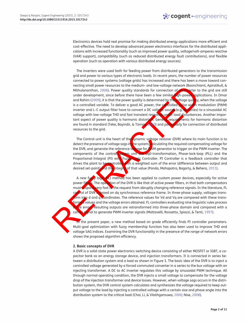
2. Basic concepts of DVRA DVR is a solid-state power electronics switching device consisting of either MOSFET or IGBT, a ca-pacitor bank as an energy storage device, and injection transformers. It is connected in series be-tween a distribution system and a load as shown in Figure 1. The basic idea of the DVR is to inject a controlled voltage generated by a forced commuted converter in a series to the bus voltage with an injecting transformer. A DC to AC inverter regulates this voltage by sinusoidal PWM technique. All through normal operating condition, the DVR injects a small voltage to compensate for the voltage drop of the injection transformer and device losses. However, when voltage sags occurs in the distri-bution system, the DVR control system calculates and synthesizes the voltage required to keep out-put voltage to the load by injecting a controlled voltage with a certain size and phase angle into the distribution system to the critical load (Choi, Li, & Vilathgamuwa, 2000; Nise, 2008).
Page 3 of 11
Deepa & Ranjani, Cogent Engineering (2015), 2: 1017243http://dx.doi.org/10.1080/23311916.2015.1017243
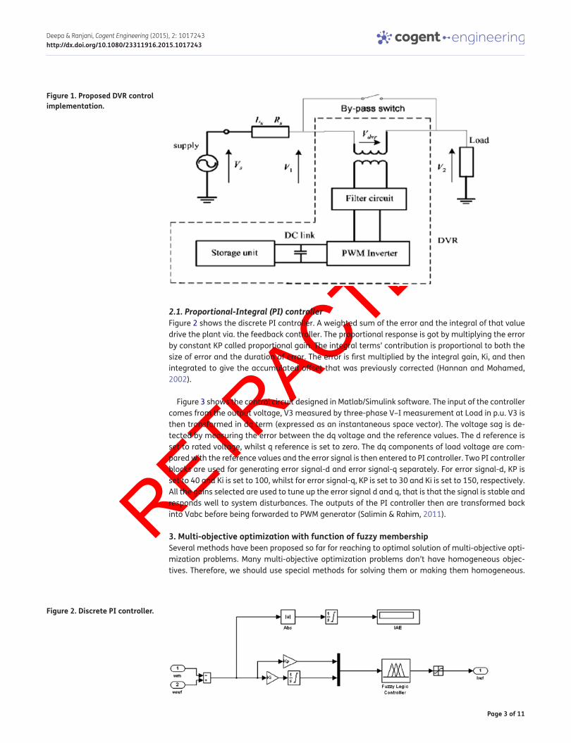
2.1. Proportional-Integral (PI) controllerFigure 2 shows the discrete PI controller. A weighted sum of the error and the integral of that value drive the plant via. the feedback controller. The proportional response is got by multiplying the error by constant KP called proportional gain. The integral terms’ contribution is proportional to both the size of error and the duration of error. The error is first multiplied by the integral gain, Ki, and then integrated to give the accumulated offset that was previously corrected (Hannan and Mohamed, 2002).
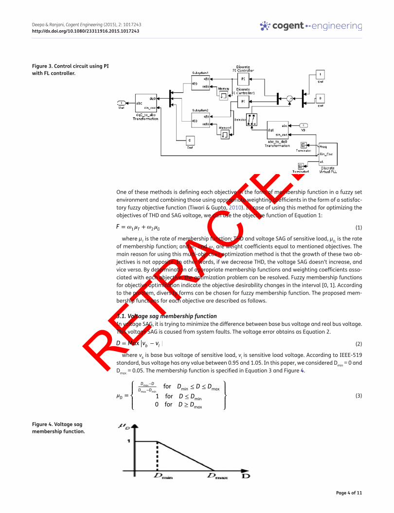
Figure 3 shows the control circuit designed in Matlab/Simulink software. The input of the controller comes from the output voltage, V3 measured by three-phase V–I measurement at Load in p.u. V3 is then transformed in dq term (expressed as an instantaneous space vector). The voltage sag is de-tected by measuring the error between the dq voltage and the reference values. The d reference is set to rated voltage, whilst q reference is set to zero. The dq components of load voltage are com-pared with the reference values and the error signal is then entered to PI controller. Two PI controller blocks are used for generating error signal-d and error signal-q separately. For error signal-d, KP is set to 40 and Ki is set to 100, whilst for error signal-q, KP is set to 30 and Ki is set to 150, respectively. All the gains selected are used to tune up the error signal d and q, that is that the signal is stable and responds well to system disturbances. The outputs of the PI controller then are transformed back into Vabc before being forwarded to PWM generator (Salimin & Rahim, 2011).
3. Multi-objective optimization with function of fuzzy membershipSeveral methods have been proposed so far for reaching to optimal solution of multi-objective opti-mization problems. Many multi-objective optimization problems don’t have homogeneous objec-tives. Therefore, we should use special methods for solving them or making them homogeneous.
Figure 1. Proposed DVR control implementation.
Figure 2. Discrete PI controller.
Page 4 of 11
Deepa & Ranjani, Cogent Engineering (2015), 2: 1017243http://dx.doi.org/10.1080/23311916.2015.1017243
One of these methods is defining each objective in the form of membership function in a fuzzy set environment and combining those using appropriate weighting coefficients in the form of a satisfac-tory fuzzy objective function (Tiwari & Gupta, 2010). In case of using this method for optimizing the objectives of THD and SAG voltage, we can use the objective function of Equation 1:
where μT is the rate of membership function; THD and voltage SAG of sensitive load, μD, is the rate of membership function; and ω1 and ω2 are weight coefficients equal to mentioned objectives. The main reason for using this multi-objective optimization method is that the growth of these two ob-jectives is not opposite. In other words, if we decrease THD, the voltage SAG doesn’t increase, and vice versa. By determination of appropriate membership functions and weighting coefficients asso-ciated with each objective, the optimization problem can be resolved. Fuzzy membership functions for objective optimization indicate the objective desirability changes in the interval [0, 1]. According to the problem, diversity forms can be chosen for fuzzy membership function. The proposed mem-bership functions for each objective are described as follows.
3.1. Voltage sag membership functionIn voltage SAG, it is trying to minimize the difference between base bus voltage and real bus voltage. This voltage SAG is caused from system faults. The voltage error obtains as Equation 2.
where vb is base bus voltage of sensitive load, vl is sensitive load voltage. According to IEEE-519 standard, bus voltage has any value between 0.95 and 1.05. In this paper, we considered Dmin = 0 and Dmax = 0.05. The membership function is specified in Equation 3 and Figure 4.
(1)F = �1�T + �
2�D
(2)D = Max ||vb − vl |
(3)�D =
⎧⎪⎨⎪⎩
Dmax
−D
Dmax
−Dmin
for Dmin
≤ D ≤ Dmax
1 for D ≤ Dmin
0 for D ≥ Dmax
⎫⎪⎬⎪⎭
Figure 4. Voltage sag membership function.
Figure 3. Control circuit using PI with FL controller.

Page 5 of 11
Deepa & Ranjani, Cogent Engineering (2015), 2: 1017243http://dx.doi.org/10.1080/23311916.2015.1017243
3.2. Voltage THD membership functionThe THD may cause irreversible effects on the sensitive load. Thus, voltage harmonic minimization can be an attractive objective. THD index is intended to determine the harmonic distortion that the membership function is specified in Equation 4 and Figure 5.
In this paper, two FL controller block is used for error signal-d and error signal-q. The process is also same as before except the controller now is FL. For both blocks (error signal-d and q), the FL control-ler consists of three linguistic variables the inputs of which are; negative (N), zero (Z), and positive (P). Each parameter form linguistic variables for error signal. Figures 6–8, respectively, show the rule viewer and surface viewer of the fuzzy controller employed.
The basic rule of FL gives the relationship between input and output. The basic rule editor compiled using the basic rules that are already available in MATLAB. Once organized into basic rule, then the examination is performed accordingly to the rule and the rule surface viewer.
Rule surface is used to see the pattern of decision-making rule base used. Rule viewer is used for approximate reasoning result FL. Entering the second input value on the rule viewer gives the result of reasoning by FL.
(4)�T =
⎧⎪⎨⎪⎩
Tmax
−T
Tmax
−Tmin
for Tmin
≤ T ≤ Tmax
1 for T ≤ Tmin
0 for T ≥ Tmax
⎫⎪⎬⎪⎭
Figure 5. Voltage THD membership function.
Figure 6. Simulink rule viewer of d reference for FL controller.

Page 6 of 11
Deepa & Ranjani, Cogent Engineering (2015), 2: 1017243http://dx.doi.org/10.1080/23311916.2015.1017243
4. GRADE optimization algorithmThe GRADE algorithm combines the features of the differential evolution with those of the traditional genetic algorithms’. It uses the simplified differential operator, but contrary to the differential evolu-tion, the GRADE method uses the algorithmic scheme very similar to the standard genetic algorithm.
The genetic operators can be written as follows:
Mutation—If a certain chromosome xi(g) was chosen to be mutated, a random chromosome xRP is generated and the new chromosome xk(g + 1) is computed using the following relation:
where MR is a parameter called mutation rate, The parameter MR is no more constant, but for each new chromosome created by mutation is randomly chosen from the interval {0,1}.
Crossing-over—The relation defining the crossing-over operator is given as:
(5)xk(g + 1) = xi(g) +MR(xRP ¡ xi(g)
(6)xk(g + 1) = max(xq(g);xr(g)) + CR(xq(g) ¡ xr(g))
Figure 8. Surface viewer for FL controller.
Figure 7. Simulink rule viewer of q reference for FL controller.
Page 7 of 11
Deepa & Ranjani, Cogent Engineering (2015), 2: 1017243http://dx.doi.org/10.1080/23311916.2015.1017243
Selection—This method uses modified tournament strategy to reduce the population size: two chromosomes are randomly chosen, compared, and the worse is rejected. Therefore, the popula-tion size is decreased by one. This step is repeated until the population reaches its original size.
The GRADE algorithm has only three parameters: pool rate, radioactivity, and CL parameter.
Algorithm and flow chart
(1) As the first step, the initial population is generated randomly and the objective function value is assigned to all chromosomes in the population. The size of the population is defined as the number of variables of the objective function multiplied by parameter pop rate.
(2) Several new chromosomes are created using the mutation operators—the mutation and the local mutation (their total number depends on the value of a parameter called radioactivity—it gives the mutation probability).
(3) More new chromosomes are created using the simplified differential operator; the whole amount of chromosomes in the population is now doubled.
(4) The objective function values are assigned to all newly created chromosomes.
(5) The selection operator applies to the double-sized population. Hence, the amount of individu-als decreases to its original value.
(6) Steps 2–5 are repeated until a stopping criterion is reached.
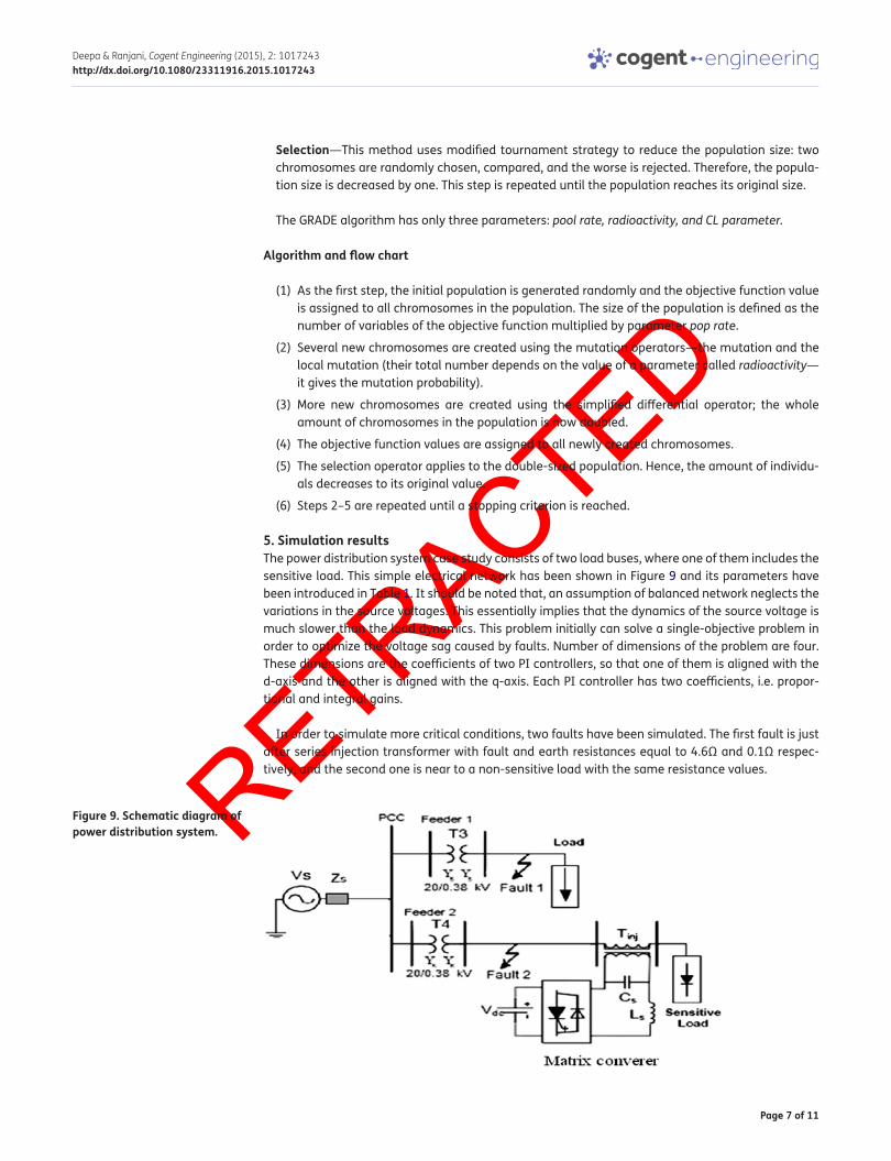
5. Simulation resultsThe power distribution system case study consists of two load buses, where one of them includes the sensitive load. This simple electrical network has been shown in Figure 9 and its parameters have been introduced in Table 1. It should be noted that, an assumption of balanced network neglects the variations in the source voltages. This essentially implies that the dynamics of the source voltage is much slower than the load dynamics. This problem initially can solve a single-objective problem in order to optimize the voltage sag caused by faults. Number of dimensions of the problem are four. These dimensions are the coefficients of two PI controllers, so that one of them is aligned with the d-axis and the other is aligned with the q-axis. Each PI controller has two coefficients, i.e. propor-tional and integral gains.
In order to simulate more critical conditions, two faults have been simulated. The first fault is just after series injection transformer with fault and earth resistances equal to 4.6Ω and 0.1Ω respec-tively, and the second one is near to a non-sensitive load with the same resistance values.
Figure 9. Schematic diagram of power distribution system.
Page 8 of 11
Deepa & Ranjani, Cogent Engineering (2015), 2: 1017243http://dx.doi.org/10.1080/23311916.2015.1017243
A GRADE algorithm with 80 iterations had been used to solve the problem. Simulation results revealed an improvement in the voltage sag of sensitive load, but in terms of harmonic index (THD), the sensitive load was not in proper condition (Table 2).
Under fault conditions at first, each objective of the problem has been turned into a fuzzy mem-bership function to solve the problem of optimization (Figure 10). In solving process, each objective has the same weight and coefficients, which are ω1 = ω2 = 0.5. We used improved GRADE algorithm to ensure that the problem results in the local optimization are not entangled. Firstly, this problem was solved using a GRADE algorithm with 80 iterations. And then, it was solved using the proposed algorithm with the same number of iterations. The obtained results from these two algorithms are given in Table 3.
Table 3 shows, maximum, minimum, and average indices of fitness function for both algorithms for an equal number of iterations. It is clear that the proposed algorithm has lower average and bet-ter responses in comparison with the standard grade algorithm. It should be noted that in order to maximize the fitness function mentioned in Equation 1, its negative variable is minimized. The con-vergence curve of the best response of proposed algorithm is shown in Figure 11.
According to this figure, the proposed algorithm reaches an acceptable response in a few itera-tions. The algorithm of this problem has been solved by 40 runs. The simulation results of PCC
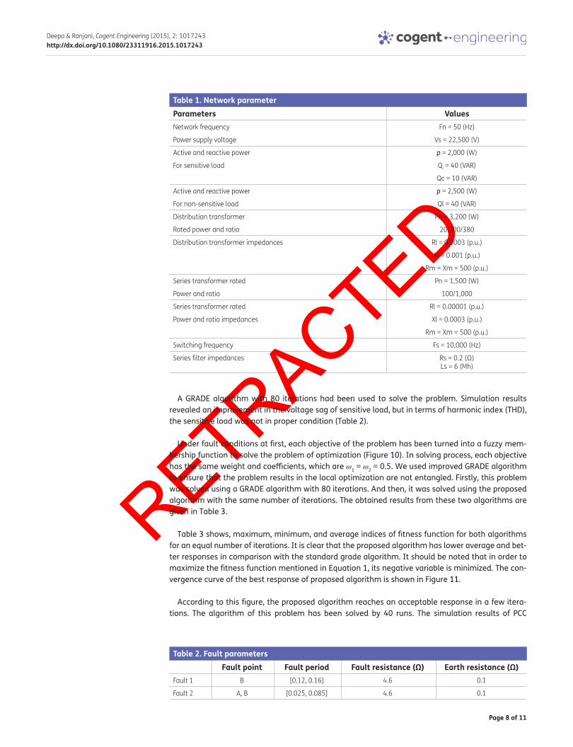
Table 1. Network parameterParameters ValuesNetwork frequency Fn = 50 (Hz)
Power supply voltage Vs = 22,500 (V)
Active and reactive power p = 2,000 (W)
For sensitive load Ql = 40 (VAR)
Qc = 10 (VAR)
Active and reactive power p = 2,500 (W)
For non-sensitive load Ql = 40 (VAR)
Distribution transformer
Rated power and ratio
Pn = 3,200 (W)
20,000/380
Distribution transformer impedances Rl = 0.0003 (p.u.)
Xl = 0.001 (p.u.)
Rm = Xm = 500 (p.u.)
Series transformer rated Pn = 1,500 (W)
Power and ratio 100/1,000
Series transformer rated Rl = 0.00001 (p.u.)
Power and ratio impedances Xl = 0.0003 (p.u.)
Rm = Xm = 500 (p.u.)
Switching frequency Fs = 10,000 (Hz)
Series filter impedances Rs = 0.2 (Ω)Ls = 6 (Mh)
Table 2. Fault parametersFault point Fault period Fault resistance (Ω) Earth resistance (Ω)
Fault 1 B [0.12, 0.16] 4.6 0.1
Fault 2 A, B [0.025, 0.085] 4.6 0.1

Page 9 of 11
Deepa & Ranjani, Cogent Engineering (2015), 2: 1017243http://dx.doi.org/10.1080/23311916.2015.1017243
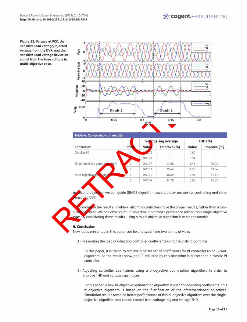
voltage, sensitive load voltage, injected DVR voltage, and the sensitive load voltage deviation from its reference value are shown in the Figure 12. Improvement in THD signal and deviation signal of baseline voltage coming from network faults in the algorithm are to be scrutinized. The result has been shown in Table 4.
In addition, results of two other controllers are given in Table 4.
As it is clear, performance of the proposed controller based on bi-objective GRADE Algorithm im-proved in comparison with single-objective type in terms of both the power quality indices. We can report that in the proposed controller, both average voltage and voltage THD indices have decreased in comparison to classical PI controllers. In other words, by considering control signal of voltage THD
Figure 10. Voltage at PCC, the sensitive load voltage, injected voltage from DVR, and the sensitive load voltage deviation signal from the base voltage in single-objective case.
Table 3. The different indices in both algorithmsMinimum Maximum Average
Standard grade algorithm −0.5747 −0.5361 −0.5554
Proposed grade algorithm −0.583 −0.5693 −0.5762
Figure 11. The best convergence curve of proposed algorithm.
Page 10 of 11
Deepa & Ranjani, Cogent Engineering (2015), 2: 1017243http://dx.doi.org/10.1080/23311916.2015.1017243
as second objective, we can guide GRADE algorithm toward better answer for controlling and com-pensating DVR.
According to the results in Table 4, all of the controllers have the proper results, rather than a clas-sical controller. We can observe multi-objective algorithm’s preference rather than single-objective type. By considering these results, using a multi-objective algorithm is more reasonable.
6. ConclusionNew ideas presented in this paper can be analyzed from two points of view:
(1) Presenting the idea of adjusting controller coefficients using heuristic algorithms:
In this paper, it is trying to achieve a better set of coefficients for PI controller using GRADE algorithm. As the results show, the PI adjusted by this algorithm is better than a classic PI controller.
(2) Adjusting controller coefficients using a bi-objective optimization algorithm, in order to improve THD and voltage sag indices:
In this paper, a new bi-objective optimization algorithm is used for adjusting coefficients. This bi-objective algorithm is based on the fuzzification of the aforementioned objectives. Simulation results revealed better performance of this bi-objective algorithm over the single-objective algorithm and classic control from voltage sag and voltage THD.
Figure 12. Voltage at PCC, the sensitive load voltage, injected voltage from the DVR, and the sensitive load voltage deviation signal from the base voltage in multi-objective case.
Table 4. Comparison of results
Controller StateVoltage sag average THD (%)
Value Improve (%) Value Improve (%)Classical PI 1 0.0205 – 4.87 –
2 0.0273 – 3.94 –
Single-objective grade algorithm 1 0.0177 13.66 1.46 70.02
2 0.0203 25.64 1.59 59.64
Multi-objective grade algorithm 1 0.0131 36.09 0.91 81.31
2 0.0178 34.79 0.96 75.63

Page 11 of 11
Deepa & Ranjani, Cogent Engineering (2015), 2: 1017243http://dx.doi.org/10.1080/23311916.2015.1017243
© 2015 The Author(s). This open access article is distributed under a Creative Commons Attribution (CC-BY) 4.0 license.You are free to: Share — copy and redistribute the material in any medium or format Adapt — remix, transform, and build upon the material for any purpose, even commercially.The licensor cannot revoke these freedoms as long as you follow the license terms.
Under the following terms:Attribution — You must give appropriate credit, provide a link to the license, and indicate if changes were made. You may do so in any reasonable manner, but not in any way that suggests the licensor endorses you or your use. No additional restrictions You may not apply legal terms or technological measures that legally restrict others from doing anything the license permits.
Cogent Engineering (ISSN: 2331-1916) is published by Cogent OA, part of Taylor & Francis Group. Publishing with Cogent OA ensures:• Immediate, universal access to your article on publication• High visibility and discoverability via the Cogent OA website as well as Taylor & Francis Online• Download and citation statistics for your article• Rapid online publication• Input from, and dialog with, expert editors and editorial boards• Retention of full copyright of your article• Guaranteed legacy preservation of your article• Discounts and waivers for authors in developing regionsSubmit your manuscript to a Cogent OA journal at www.CogentOA.com
FundingThe authors received no direct funding for this research.
Author detailsS. Deepa1
E-mail: [email protected]. Ranjani2
E-mail: [email protected] Electrical Department, Panimalar Institute of Technology,
Chennai, India.2 Electrical Department, Sathyabama University, Chennai,
India.
Citation informationCite this article as: Dynamic voltage restorer controller using grade algorithm, S. Deepa & M. Ranjani, Cogent Engineering (2015), 2: 1017243.
ReferencesBoonchiaml, P., Apiratikull, P., & Mithulananthan, N. (2006).
Detailed analysis of load voltage compensation for dynamic voltage restorers. In IEEE Region 10 Conference (TENCON) (pp. 1–4). Hong Kong, China.
Choi, S. S., Li, B. H., & Vilathgamuwa, D. D. (2000). Dynamic voltage restoration with minimum energy injection. IEEE Transactions on Power Systems, 15, 51–57. http://dx.doi.org/10.1109/59.852100
Hannan, M. A., & Mohamed, A. (2002). Modeling and analysis of a 24-pulse dynamic voltage restorer in a distribution system. In Student Conference on Research and
Development Proceedings (pp. 192–195). Shah Alam, Malaysia. http://dx.doi.org/10.1109/SCORED.2002.1033090
Mattavelli, P., Rossetto, L., Spiazzi, G., & Tenti, P. (1997). General-purpose fuzzy controller for DC–DC converter. IEEE Transactions on Power Electronics, 12, 79–86.
Nise, N. S. (2008). Control systems engineering (5th ed.). Hoboken, NJ: Wiley.
Omar, R., & Rahim, N. A. (2009). New control technique applied in dynamic voltage restorer for voltage sag mitigation. In Industrial Electronics and Applications, ICIEA 2009. 4th IEEE Conference (pp. 848–852). Ayer Keroh, Malaysia.
Panda, B., Mahapatra, A. K., Bagarty, D. P., & Behera, S. (2011). Fuzzy logic controller-based dynamic voltage restorer for mitigation of voltage sag. International Journal of Engineering Science and Technology (IJEST), 3, 996–1007.
Salimin, R. H., & Rahim, M. S. A. (2011, June 6–7). Simulation analysis of DVR performance for voltage sag mitigation. In The 5th International Power Engineering and Optimization Conference (PEOCO 2011) (pp. 261–266). Shah Alam, Selangor, Malaysia. http://dx.doi.org/10.1109/PEOCO.2011.5970386
Teke, A., Bayindir, K., & Tumay, M. (2010). Fast sag/swell detection method for fuzzy logic controlled dynamic voltage restorer. IET Generation, Transmission & Distribution, 4(1), 1–12. http://dx.doi.org/10.1049/iet-gtd.2009.0423
Tiwari, H. P. & Gupta, S. K. (2010). Dynamic voltage restorer against voltage sag. International Journal of Innovation, Management and Technology, 1, 232–237.