Embed Size (px)
Citation preview

RetroFAST® Installation Manual FOR USE WITH
(ETV/EPA tested) RetroFAST® .150, .250, .375
RetroFAST Manual © 2012 Bio-Microbics, Inc. Revised December 2012. RetroFAST is a registered trademark used under license by Bio-Microbics, Inc.
RetroFAST®
wastewater treatment systems

INSTALLATION MANUAL FOR USE WITH
(ETV/EPA tested) RetroFAST® .150, .250 and .375
GENERAL INFORMATION The RetroFAST process has been tested and verified in the USEPA (Environmental Protection Agency) ETV (Environmental Technology Verification) program (RetroFAST 0.375 tested). All FAST® products are ETL certified for safety (electrical, environmental, etc.). One or more of the following patents protects this process: 3,966,599; 3,966,608; 3,972,965; 5,156,742. If you have questions regarding any Bio-Microbics products, please contact us:
800-753-FAST (3278) or (913) 422-0707 e-mail: [email protected]
DELIVERY INSPECTION Every FAST® system is designed and inspected to meet stringent quality assurance standards prior to shipment. Check the packaging for signs of shipping damage before and after uncrating the unit. If there is evidence of damage or abuse, notify Bio-Microbics, Inc. at (800) 753-3278 or (913) 422-0707. About FAST®: The FAST® (Fixed Activated Sludge Treatment) system uses naturally occurring bacteria (biomass) to treat sewage for dispersal into the environment. This continuous process provides the biomass with waste (food) and air in a suitable environment. Dead bacteria and non-biodegradable waste settle and accumulate in the bottom of the septic tank for periodic removal. The FAST® process consists of the treatment module and blower. The blower provides air to the system via the air supply pipe. The air supply pipe and draft tube create an air lift. The air lift mixes oxygen and waste throughout the media inside the tank. Bacteria grow on the media and digest the waste. A vent pipe expels harmless vapors created by the process.
Dear Septic System Owner Thank you for purchasing a Bio-Microbics RetroFAST® septic system enhancement to upgrade your existing system. Engineered and manufactured to meet the highest industry standards by the leader in onsite wastewater equipment, the FAST® System is. at the forefront of green technology. Based on environmentally sound and simple scientific principles, the FAST® process is our continued commitment to improve small onsite treatment capabilities. You can take pride in knowing that, with the FAST® system, you will help ensure a clean environment for future generations.
Please take time to read this FAST® Owner’s Manual, you will learn important safety precautions, review detailed information on proper use and care of your system. Designed for minimal operator attention, the FAST® System contains only one moving part – the blower. By consistently following a maintenance schedule and being mindful of what can go down your drains, you can enjoy the lasting benefits FAST® Wastewater Treatment System for decades to come.
Top things you can do to prolong the life of your system:
1. Keep track of the substances entering your system, please review the list of Do’s & Don’ts (see other side for poster). 2. Have the FAST® system inspected and tank pumped as necessary. 3. Keep the FAST® System operating - do not turn off the blower. 4. Care for your drain field or irrigation system (if incorporated into your FAST® System).
If you should desire any further assistance, please contact Bio-Microbics at [email protected] or call us at 800-753-FAST (3278).
Thank you again for using RetroFAST®! Sincerely, Bio-Microbics Team

SYSTEM COMPONENTS RetroFAST® Septic System Enhancement System includes the following components:
LOCATION Always have all utility lines and equipment marked by a locating service prior to performing any work. Failure to do so could result in severe bodily injury or death.
MODULE SIZE AND WEIGHTS
RTF .150 16” L (41 cm) x 16” W (41 cm) x 32” H (81 cm) 74 lbs [33.5 kg]
RTF .250 28” L (71.1 cm) x 24” W (61 cm) x 33.5” H (85.1 cm) 130 lbs [59 kg]
RTF .375 41” L (104.1 cm) x 24” W (61 cm) x 33.5” H (85.1 cm) 156 lbs [70.8 kg]
blower
access Vent / Observation
inlet
settling area
outlet
5
tank RetroFAST® Unit
7
2
13
4
6
air piping
PART NAME PART NUMBER
1 RetroFAST® Lid 010-CVRG25-375
2 Blower 020-1/4HPPAC
3 1.5" Air line gasket 050-GSKT2R
6" O/V gasket 050-GSKT8
RetroFAST® Manual RTF manual
4 Blower housing 250-BBHSFL
5 3" Outlet gasket 050-GSKT3
6 Liner Model dependant
7 Blower piping & screws 720-BLPRTS1/4HP
RetroFAST® systems may be located in the same position relative to the house and water supply as any conventional septic system. However, some basic guidelines should be followed:
1. RetroFAST® system cover is designed to withstand a burial depth of up to 4 feet (1.2 meters). Do not place the tank in a location where it could be subjected to additional weight.
2. RetroFAST® system must be located so that sufficient slope (≥2%, ¼ inch/foot) is provided for the influent and effluent lines.
3. Excessive back pressure must not be placed on the blower. Follow all installation guidelines.
4. Method and arrangement for effluent discharge must not interfere with the system’s operation.
5. If the tank is smaller than the minimum dimensional range specified, the RetroFAST system may not operate properly. The effluent quality could suffer and may not meet standards.

INSTALLATION PROCEDURE *PLEASE NOTE: There maybe associated equipment with your system: pumps (before and/or after the FAST® unit), distribution box, disinfection system, irrigation system, remote alarm, auto dialer, etc.
Only qualified service people should open any access port on a septic system. Infectious organisms exist in a septic tank. Persons coming in contact with wastewater must immediately wash and disinfect all exposed areas and contact their personal physician. Failure to do so could result in severe
sickness or death.
MATERIALS REQUIRED FOR INSTALLATION 1. Septic tank that meets all applicable
requirements and standards
2. Safe lifting mechanism (RetroFAST® units weigh ≤130 lbs [59 kg]
3. Anchor bolts for securing RetroFAST® unit to the tank and blower housing to the concrete base.
4. Piping for observation/vent port, air lines, and vent lines (check installation procedures, specs, and plans to determine the size and type of pipes needed).
5. PVC saw
6. Pipe lubricant/soap
7. PVC primer and glue (weather appropriate)
8. Concrete base for blower assembly
9. Electrical conduit, fittings and specified wires
10. Hammer, drill, and masonry bits appropriate for anchor bolts
Persons coming in contact with wastewater, must immediately wash all exposed areas with disinfecting cleaner and contact your personal physician. Failure to do so could result in severe sickness or death.Hazards exist in confined spaces, such as a septic tank. If entering the tank, use necessary
precautions. Always keep tank openings covered during storage and installation.
MODULE INSTALLATION
For best results, read the entire installation procedure before beginning. Check the tank to ensure it is level within ±1/2” [12 mm]. Before starting installation, take close look of the RetroFAST® unit in its shipping container. Note the position and orientation of all components. The installation procedures will require disassembly of the unit outside the tank, and then reassemble it inside the tank. The airlift sits in the center of the unit, which has a recirculation trough attached to it that protrudes through the edge of the liner, opposite the effluent pipe opening. The media is cut into four (4) pieces that fit together in one specific manner. All of these parts are contained in the liner that has two attached flaps at the top.
NOTICE: You must have your tank pumped out in compliance with local health and environmental regulations prior to RetroFAST® installation. Once the septic tank is pumped out, the installation of the module may begin.
INSTALLING LINER
1. Take all parts including the airlift and media out of the liner. Clear the debris around the septic tank and open the lid.
2. Fold up the module liner and lower it through the manhole of the septic tank. Keep flaps on top of tank as show in pic to the right. Unfold liner inside the tank.
3. Insert proper length of 3” [76 mm] Sch 40 PVC pipe into RetroFAST®’s effluent hole and gasket, being careful to only insert the pipe until it rests on the pipe stops that are in the effluent chamber.
4. Insert the 3” pipe into the outlet of the existing tank (you may have to modify the baffle of the existing tank).
5. Adjust level of the RetroFAST unit so that the 3” outlet pipe rests 1/2–2” [12–51 mm] higher than the existing tank outlet.
6. Seal the 3” outlet pipe to the tank’s existing outlet pipe.
FLAPS
Step 2: Insert Liner
3” outlet gasket & baffle stops
3” outlet pipe must have downward slope
Step 3, 4, and 5: Outlet Pipe

7. Use non-corrosive concrete anchor bolts to fasten the flaps of the RetroFAST® unit to the septic tank or tank’s riser. Place the media back into the liner, being careful to install the pieces with the original orientation
8. Then install the airlift into the center of the media making ‘sure to orient the recirculation trough opposite the effluent hole and so that the end inserts through the small hole in the liner. The airlift MUST be installed so that the “collar” rests on the media as before.
9. AIR LINE Insert cut length of 1.5” [38 mm] air supply pipe through factory provided air line gasket in module lid. Use 6” hole in the lid to connect & glue air supply to air lift coupling. Run the air line to the desired blower location using required piping. Blower piping to RetroFAST® may not exceed 100 ft [30.5 m] total length with ≤ 4 elbows.
ALL CONNECTIONS MUST BE AIR / WATER TIGHT AND PERMANENT.
10. OBSERVATION/VENT PORT (o/v port) Insert desired length of 6” pipe into factory provided gasket then into access hole in lid. Insert pipe until it stops. DO NOT PUSH PIPE TO MEDIA SURFACE!
11. VENTING Numerous options exist for proper venting. Three of the most common are mentioned here. The vent system must be sized properly to avoid excessive back pressure in the system (see table below). It also must not allow surface water to enter the system and must allow internal condensation to drain. DIRECT VENT: The 6” o/v port can have holes drilled in it or a slotted cap put on it. Any cap must be fastened with screws to prevent unauthorized access. The opening(s)
should prevent foreign material from entering the system. REMOTE VENT: Branch the ≥3” vent pipe off the 6” o/v port or manhole below grade and then run the vent pipe to the desired location and terminate above grade. Cover opening with #4-mesh screen or similar. Water accumulating in the vent piping MUST be drained to prevent backpressure. BIOFILTER: This method may require design by a qualified engineer. Run a significant amount of perforated vent line in a trench. Cover the trench with shredded bark mulch. DO NOT cover
the mulch with soil.
NOTE: A biofilter vent must not allow moisture to back into the treatment system.
BLOWER INSTALLATION
Always have all utility lines and equipment marked by a locating service prior to performing any work. All electrical work shall be properly performed by a qualified electrician per all applicable codes. Failure to do so may result in severe bodily injury or death.
The blower housing must be placed on a concrete slab. All conduit/piping should pass through the concrete slab from below. 1. CONNECT SUPPLIED INITIAL PIECES
a. Longest pipe b. Elbow c. Air filter assembly d. Shortest pipe e. Reducer bushing
NOTE: All aonnections must be air/water-tight and permenant. USE TEFLON SEALANT TAPE ON ALL PIPE CONNECTIONS.
2. SECURE BLOWER assembly to housing base using four supplied #14 x 1½” self-tapping screws. Drill screws directly into blower base.
2" air line hole
6" O/V hole
Step 9-10: Lid
Insert trough into recirc hole
Step 7-8: Replace Parts

3. CONNECT AIR LINE from RetroFAST® unit to blower outlet using required 1.5” [3.8 cm] piping. Blower piping to RetroFAST® may not exceed 100 ft [30.5 m] total length and have ≤ 4 elbows. Keep all debris out of air line.
CONTROL PANEL INSTALLATION (OPTIONAL)
All electrical work shall be performed by a qualified electrician per all applicable codes. Failure to do so may result in severe bodily injury or death.
The RetroFAST® system including all electrical parts are ETL (UL equivalent) certified for electrical safety. The optional control panel meets NEMA4X standards for all weather use (not explosive or submerged environments). Bio-Microbics also manufactures other control panels that can control UV systems and sewage pumps. The TRACK system (or other auto-dialers) can connect to these panels.
1. Examine wiring directions inside the supplied FAST® control panel
2. A dedicated breaker is required in the building’s master electrical panel. Make connections between the master panel and FAST® control panel
3. Make connections between the blower and FAST® control panel per the electrical diagram
FINAL INSTALLATION INSPECTION & START UP
It is the responsibility of the installer to ensure that the tank will not float due to hydraulic conditions at the site. Your local FAST® Systems distributor may provide installation inspection services. If you have questions, call Bio-Microbics at 1-800-753-FAST or (913)422-0707.
Persons coming in contact with wastewater, must immediately wash all exposed areas with disinfecting cleaner and contact your personal physician. Failure to do so could result in severe sickness or death.
BEFORE THE UNIT IS BACKFILLED: 1. Fill the tank to the normal operating level. 2. Check for leaks in all water-tight seals. 3. Turn the blower ON and observe the operation of the airlift.
A robust splash should be present. 4. Check for excessive back pressure: Seal all access covers,
place hand about 8 inches [20 cm] from FAST® vent, if air flow is felt then excessive back pressure exists and the system’s vent must be upgraded.
5. Check for proper water level over the media. The normal
water line should be ~2” [5 cm] over the media. 6. Check for proper alarm function. Turn OFF the blower circuit
breaker and wait for the alarm to sound. If the alarm does not sound after 30 seconds, then review the electrical installation procedures.
7. Turn the blower back ON. 8. Backfill the excavation. 9. Lastly, record the FAST® unit’s serial number in the Service
Manual.
ELECTRICAL DIAGRAMS
AMI 110/220 PANEL (2 FRONT LIGHTS)
110VAC “CSI” PANEL W/ 3 FRONT LIGHTS

BLOWER DIAGRAMS ATTENTION: Please refer to side of shipping box for correct Blower
LIMITED WARRANTY
Bio-Microbics, Inc. warrants every new residential FAST® system against defects in materials and workmanship for a period of two years after installation or three years from the date of shipment, subject to the following terms and conditions, (Commercial FAST system for a period of one year after installation or eighteen months from date of shipment, whichever occurs first, subject to the following terms and conditions): During the warranty period, if any part is defective or fails to perform as specified when operating at design conditions, and if the equipment has been installed and is being operated and maintained in accordance with the written instructions provided by Bio-Microbics, Inc., Bio-Microbics, Inc. will repair or replace at its discretion such defective parts free of charge. Defective parts must be returned by owner to Bio-Microbics, Inc.’s factory postage paid, if so requested. The cost of labor and all other expenses resulting from replacement of the defective parts and from installation of parts furnished under this warranty and regular maintenance items such as filters or bulbs shall be borne by the owner. This warranty does not cover general system misuse, aerator components which have been damaged by flooding or any components that have been disassembled by unauthorized persons, improperly installed or damaged due to altered or improper wiring or overload protection. This warranty applies only to the treatment plant and does not include any of the structure wiring, plumbing, drainage, septic tank or disposal system. Bio-Microbics, Inc. is reserves the right to revise, change or modify the construction and/or design of the FAST system, or any component part or parts thereof, without incurring any obligation to make such changes or modifications in present equipment. Bio-Microbics, Inc. is not responsible for consequential or incidental damages of any nature resulting from such things as, but not limited to, defect in design, material, or workmanship, or delays in delivery, replacements or repairs. THIS WARRANTY IS IN LIEU OF ALL OTHER WARRANTIES EXPRESS OR IMPLIED. BIO-MICROBICS SPECIFICALLY DISCLAIMS ANY IMPLIED WARRANTY OF MERCHANTABILITY OR FITNESS FOR A PARTICULAR PURPOSE. NO REPRESENTATIVE OR PERSON IS AUTHORIZED TO GIVE ANY OTHER WARRANTY OR TO ASSUME FOR BIO-MICROBICS, INC., ANY OTHER LIABILITY IN CONNECTION WITH THE SALE OF ITS PRODUCTS.
Fuji Atlantic
Gast FPZ/Lafert
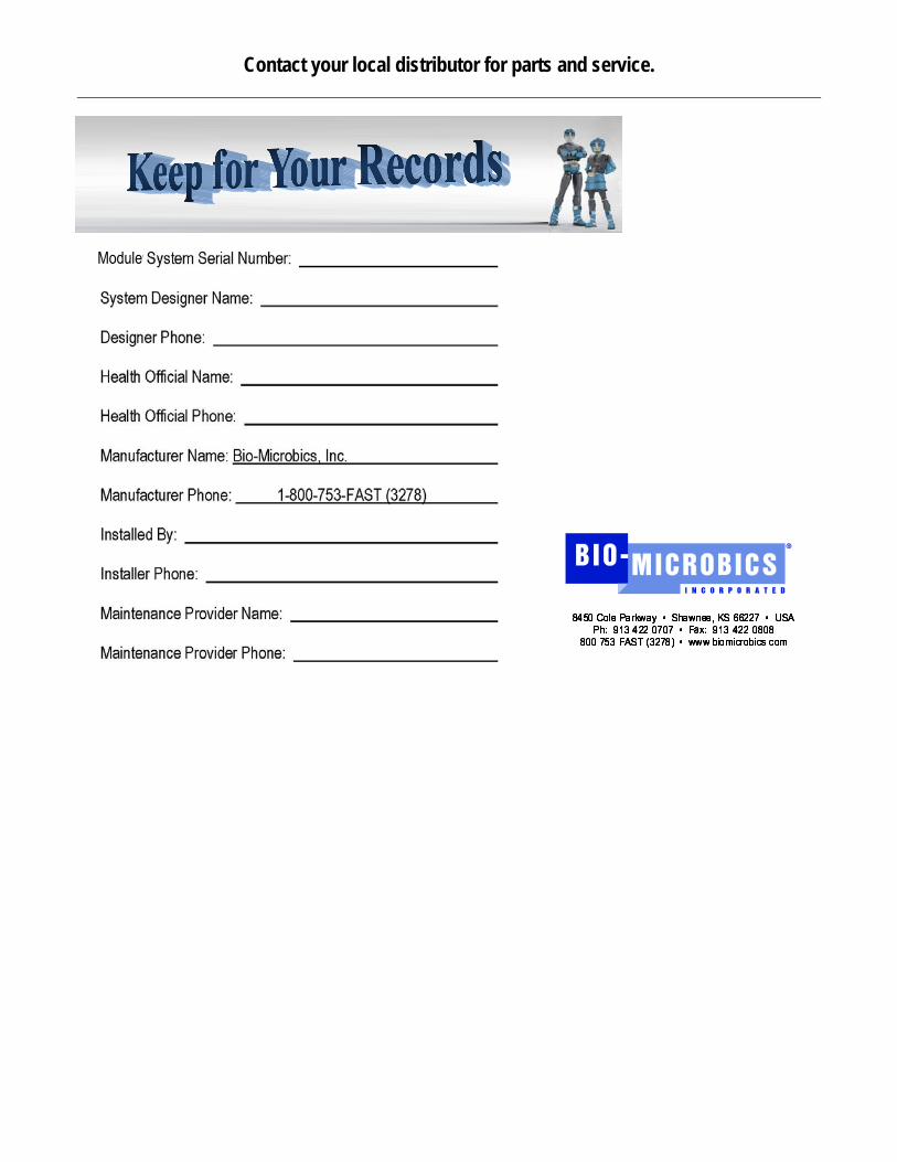
Contact your local distributor for parts and service.