Embed Size (px)
Citation preview

, Report Issued:Revision 1
Report 420-85.687
PACIFIC GAS AND ELECTRIC COMPANY
DEPARTMENT OF ENGINEERING RESEARCH
EVALUATION OF DIABLO CANYON POWER PLANTREACTOR VESSEL MATERIALS BY THE NRC
PRESSURIZED THERMAL SHOCK SCREENING CRITERIA
Prepared By: Approved By:
M. D. SULLIVAN, Consultant R. D KE , Senior Welding Engineer
W.C. upervising MetallurgicalEngineer
pe %23 Cg., 0500027500gg 860i~7
@gal
„gQQCH'gR


~ > o
Revision IReport 420-85.687
SUMMARY
The Diablo Canyon reactor pressure vessel beltline materials have been evaluated
according to the Nuclear Regulatory Commission's Pressurized Thermal Shock (PTS)
Rule. Reference Temperature for Pressurized Thermal Shock, RTPTS, has been
calculated for each weld metal and base metal in the beltline region for neutron
fluences from 1017 n/cm2 through 40 effective full power years design life.
RTPTS for all materials is less than the PTS Rule screening limit of 270F for
base metal and longitudinal welds, and 300F for circumferential welds. With the
present design basis out-in-in fuel loading pattern, Unit 1 could operate for 80
effective full power years, and Unit 2 could operate for 128 effective fullpower years before reaching the PTS Rule screening limit. Since all materials
meet the screening criteria, neither a flux reduction program nor additional
analyses are required to comply with the PTS Rule.
0485a/dk3


Revision 1
Report 420-85.687
TABLE OF CONTENTS
PAGE
UMMARY ~ ~ ~ ~ o ~ ~ ~ ~ ~ ~ ~ ~ ~ ~ ~ ~ t ~ ~ ~ ~ ~ ~ ~ ~ ~ ~ ~ ~ ~ ~ ~ ~ ~ ~ ~ ~ ~ ~ ~ ~ ~ ~ ~ ~ ~ ~ ~ ~ ~ ~ ~ ~ ~ ~ ~ ~ ~S
TABLE OF CONTENTS
LIST OF TABLES ..................................".................. ii).
LIST OF FIGURES ................................................... iv
1 ~.0 INTRODUCTION ................................................. 1
2.0 PTS RULE SCREENING CRITERIA .................................. 3
3.0 EVALUATION OF DCPP MATERIALS ................................. 5
3.1 Weld Metal Compositions ................................. 5
3.2 Weld Metal Initial Reference Temperature, RTNDT ......... 8
3.3 Base Metal Compositions 8
3.4 Base Metal Initial Reference Temperature, RTNDT ........ 9
3.5 End Of Life Fluence 9
3 .6 Prospected RTPTS ~ ~ ~ ~ ~ ~ ~ ~ ~ ~ ~ ~ ~ ~ ~ ~ ~ ~ ~ ~ ~ ~ ~ ~ ~ ~ ~ ~ ~ ~ ~ ~ ~ ~ . ~ ~ ~ ~ ~ 10
4.0 CONCLUSIONS .................................................. 11
5 .0 REFERENCES 13
APPENDIX A: PTS RULE CALCULATIONS FOR DIABLO CANYON UNIT 1
REACTOR VESSEL MATERIALS
APPENDIX B: PTS RULE CALCULATIONS FOR DIABLO CANYON UNIT 2
REACTOR VESSEL MATERIALS
A-1
B-1
0485a/dk3

Revision 1
Report 420-85.687
LIST OF TABLES
PAGE
TABLE 1 Diablo Canyon Reactor Vessel Beltline Region SubmergedArc Weld Materials 14
TABLE 2 Diablo Canyon Unit 1 Submerged Arc Weld Deposit AnalysesFor Reactor Vessel Beltline Region ....................... 15
TABLE 3 Diablo Canyon Unit 2 Submerged Arc Weld Deposit AnalysesFor Reactor Vessel Beltline Region ....................... 16
TABLE 4 Diablo Canyon Unit 1 Reactor Vessel Beltline RegionPlate Materxal ........................................... 17
TABLE 5 Diablo Canyon Unit 2 Reactor Vessel Beltline RegionPlate Material ........................................... 18
TABLE 6 Summary of PTS Rule Evaluation of RPV Beltline Materialsfor Da.ablo Canyon Unit 1 ................................. 19
TABLE 7 Summary of PTS Rule Evaluation of RPV Beltline Materialsfor Diablo Canyon Unit 2 ................................. 20
0485a/dk3


Revision 1
Report 420-85.687
LIST OF FIGURES
PAGE
FIGURE 1 RTPTS As A Function of Neutron Fluence For DCPPUnit 1 Reactor Vessel Materials ........................ 21
FIGURE 2 RTPTS As A Function of Neutron Fluence For DCPPUnit 2 Reactor Vessel Materials ........... ............ 22
0485a/dk3


Revision 1
Report 420-85.687
1.0 INTRODVCTION
Pressurized Thermal Shock (PTS) is the term used to describe an upset event in a
Pressurized Water Reactor which produces a severe overcooling of the inside
surface of the reactor vessel wall, concurrent with or followed by
repressurization. The steep temperature gradient through the wall creates high
tensile stresses, which when coupled with the tensile stress due to internal
pressure could cause cracks to propagate from preexisting defects.
The ability of the pressure vessel to withstand a PTS event is dependent on the
fracture toughness of the materials, and the location, size, and orientation of
any flaws which may exist in the vessel. For a given material, fracture
toughness generally decreases with decreasing temperature and increasing neutron
fluence. Because of the dependence on fluence, a severe PTS event which occurs
after the vessel has experienced significant irradiation is more likely to cause
unstable crack growth than if the same event occurred early in the vessel life.
The NRC has developed screening criteria[1), herein called the PTS Rule, to
identify reactor vessels which may, at some time in the plant life, have
inadequate toughness to safely withstand a PTS event. The measure of fracture
toughness used in the PTS Rule is Reference Temperature for nil-ductilitytransition, RTNDT. RTNDT is based on the temperature at which the material
exhibits a change from ductile to brittle behavior in the dropweight and Charpy
V-notch tests. A low RTNDT indicates that the transition from ductile to
0485a/dk3


Revision 1
Report 420-85.687
brittle behavior occurs at a low temperature and is generally indicative of high
toughness. A high RTNDT indicates that the material can behave in a brittle
manner even at high temperature, and generally indicates low toughness. The
procedure for determining the initial RTNDT is given in ASME Boiler and Pressure
Vessel Code, Section III, Paragraph NB-2331.
The PTS Rule predicts the change in RTNDT as a function of neutron fluence for a
material of a given composition. When the reference temperature is calculated
by the PTS Rule equation, it is called RTPTS to distinguish it from a measured
value of RTNDT. When the predicted RTPTS exceeds the screening limit, neutron
fluence must be reduced so that the screening limit is not exceeded, or
additional analyses must be performed to verify that adequate fracture toughness
exists through the end of life.
The PTS Rule became effective on July 23, 1985 and requires for all operating
Pressurized Water Reactors that projected values of RTPTS from the present time
to the expiration date of the operating license be submitted for all beltline
materials.
In this report the Diablo Canyon Units 1 and 2 reactor vessel materials are
evaluated by the PTS Rule. Values of RTPTS are calculated for each of the
baseline materials through 40 Effective Pull Power Years (EFPY) of operation.
0485a/dk3


Revision 1
Report 420-85.687
2.0 PTS RULE SCREENING CRITERIA
The PTS Rule screening criteria consist of two equations which estimate the
adjusted reference temperature, RTPTS, as a function of weight percent copper
and nickel, fast neutron fluence and initial reference temperature, RTNDT.
RTPTS is the lower of the values calculated by both equations.
Equation 1 is as follows:
RTPTS = I + M + [-10 + 470Cu + 350CuNi] f
Where: "I" is the initial reference temperature, RTNDT, of the subject
material measured as defined in ASME Code, Section III, Paragraph
NB-2331. When a measured value for submerged arc weld metal is not
available, a generic value which is a function of submerged arc flux
type must be used. For all DCPP weld metal, the generic value is -56F.
"M" is the margin to be added to account for uncertainties in the
values of initial RTNDT, copper and nickel content, and the
calculational procedure. When the RTNDT is a measured value, M equals
48F. When it is estimated, M equals 59F.
"Cu" and "Ni" are the best estimates of weight percent of copper and
nickel in the material.
0485a/dk3

0

Revision 1
Report 420-85.687
"f" is the best estimate of fast neutron fluence at the clad/base metal
interface, in units of 10 neutrons/cm
Equation 2 is as follows:
RTPTS = I + M + 283 f
Equation 2 is the upper bound of the Regulatory Guide 1.99, Rev 1[2] curve and
is independent of material chemistry. For all materials in the DCPP reactor
vessels, Equation 1 gave the lower RTPTS, so all values reported here are
calculated by Equation I/1.
The PTS Rule requires that RTPTS be calculated for each plate, forging and weld
in the beltline region. The beltline region is defined as the part of the
vessel that directly surrounds the effective height of the active core, and
other adjacent regions that experience significant fluence. At DCPP, the
beltline region includes only the intermediate, and lower shell courses and the
lower portion of the upper shell course. The remainder of the vessel does not
experience sufficient fluence to be considered in evaluating the most limiting
materials.
The PTS Rule establishes an upper limit on RTPTS of 270F fox. base material and
longitudinal welds and 300F for circumferential welds. When RTPTS for a
material is less than the screening criteria, the material is considered to have
adequate toughness to prevent brittle fracture during a pressurized thermal
0485a/dk3

0
Revision 1Report 420-85.687
shock event. When a material exceeds the screening criteria, additional action
by the owner is required to ensure that the material has adequate fracture
toughness during the period of the operating license.
3.0 EVALUATION OF DCPP MATERIALS
The material properties used in this evaluation were obtained from PGSE report
"Properties of Reactor Vessel Material For Diablo Canyon Units 1 and 2" [3].
This report is the result of an extensive search of fabrication records from
Combustion Engineering, Westinghouse, and the surveillance program reports of
other utilities. Data tables from the above referenced report are also included
in this report for convenience.
3.1 Weld Metal Compositions
Table 1 identifies the submerged arc wi.re heat number, flux type and lot number
for all beltline welds. This information was obtained from Combustion
Engineering records.
Both submerged arc {SAW) and shielded metal arc (SMAW) processes were used to
fabricate the vessel, but the submerged arc process was used predominantly. SMAW
was normally used for rewelding the root pass after backgouging and for repairs.
A review of the SMAW deposit compositions shows that copper content for allwelds was <.04 wt%, and nickel content was approximately 0.5 wtZ. These low
copper and nickel weldments suffer an insignificant shift in RTNDT during
0485a/dk3

Revision 1
Report 420-85.687
the plant lifetime relative to the submerged arc welds. For a weld of the above
composition, an RTNDT shift of only 21F is predicted by the PTS Rule. Because
of the small RTNDT shift, SHAW welds are not of concern, and are not further
discussed in this report.
Host of the submerged arc weld deposit chemistry data were obtained from
Combustion Engineering records. In most cases, CE performed chemical analyses
on either a test weldment used to qualify the combination of submerged arc wire
and flux, or on a production weldment. Analyses results were reported in the
Metallurgy and Materials Laboratory (MML) Log Book. Other analyses were
obtained from DCPP surveillance capsule weldments and surveillance capsule
weldments of other utilities.
Tables 2 and 3 list all available chemical analyses for the weld metal in the
beltline region weld seams for Unit 1 and Unit 2 respectively. Except where
noted, the analyses are of deposited weld metal made with a copper coated weld
wire of the noted heats and flux lots. In most instances the tested weld
deposits were made with the same type of flux and in some instances, with the
same lot of flux as the Diablo Canyon welds.
Tables 6 and 7 are the best estimates of the mechanical and chemical properties
used to predict radiation-induced RTNDT shift by the PTS Rule. To arrive at
these estimates for weld metal chemical composition, the data in Tables 2 and 3
were evaluated using the following criteria to determine the compositions most
representative of the vessel welds.
0485a/dk3

0
Revision 1
Report 420-85.687
Weld metal analysis obtained from a DCPP reactor vessel weld seam was judged to
be the most representative and was used in preference to all other data. Ifmore than one vessel weld analysis was available, a mean value was used.
Analyses obtained from the DCPP surveillance capsule weldments were judged to be
the next most representative and were used in preference to all data except
vessel weldment analysis. Surveillance capsule welds were made at the same time
and with the same welding procedure specification and base plates as the reactor
vessel weldments and were judged to be representative of the vessel welds made
with that wire heat. When both vessel and surveillance capsule data were
available, a mean value was used.
In the absence of the above data sources, a mean value of all available groove
weld data for that wire heat was used. The mean values are not considered as
representative as the vessel weld or surveillance capsule weld data because of
the unknowns about the welds from which the analyses were made.
The intermediate and lower shell longitudinal welds in Unit 1 were made with
Heat 27204 and Linde 1092 flux, the same as used in the Unit 1 surveillance
capsule weldment. For these welds, the composition reported in WCAP 8465,
"Diablo Canyon Unit 1 Reactor Vessel Radiation Surveillance Program [4] was
used.
The composition of the Unit 1 upper shell longitudinal weld made with Heats
12008/27204 was obtained from the Mihama Unit 1 surveillance capsule report[5].
0485a/dk3

Revision 1
Report 420-85.687
For the tandem heats of 21935/12008 in Unit 2, chemical analyses were available
both from the surveillance capsule weldment and from three coupons taken from an
intermediate shell longitudinal weld. These four data points were averaged.
The copper and nickel values for Heats 13253, 10120 and 21935 are averages
of all available deposited weld metal data given in Tables 2 and 3.
3.2 Weld Metal Initial Reference Temperature (RTNDT)
Dropweight and Charpy tests were not routinely performed for reactor vessel weld
metal in the period when the DCPP vessels were fabricated. In more recent
vessels, these tests were required by the ASME Code. For DCPP vessels, only the
weld metal in one test weldment per vessel was tested in this way. Combustion
Engineering performed dropweight and Charpy tests on weldments made from Heats
27204/12008 for Unit 1, and Heats 21935/12008 for Unit 2. When weld metal
dropweight tests were not performed, initial RTNDT had to be estimated in
accordance with the PTS Rule. All of the DCPP weldments were made with either
Linde 1092, 0091, or 124 flux. For these materials, the estimated RTNDT is
-56F. RTNDT for'these materials is given in Tables 6 and 7.
3.3 Base Metal Compositions
The reactor vessel shell plates for both units were supplied by Lukens Steel to
ASTM A 533 Grade B, Class 1, with additional requirements of ASME Code, Section
III, Code Case 1339-2. The compositions of the shell plates were determined
0485a/dk3


Revision 1
Report 420-85.687
from Lukens Steel or Combustion Engineering material test reports. The elements
required by the ASTM material specification were reported, but in most cases
copper was not because it was not controlled by specification. Copper contents
were obtained from the ladle analysis by Lukens Steel Company as reported to
Westinghouse[6]. Chemical compositions of the upper, intermediate, and lower
shell plates are given in Table 4 for Unit 1 and Table 5 for Unit 2.
3.4 Base Metal Initial Reference Temperature (RTNDT)
At the time the DCPP reactor vessels were constructed, ASME Code did not require
both dropweight and transverse Charpy testing of base plate. Therefore RTNDT
values were not readily available, but had to be pieced together from data from
Combustion Engineering and Westinghouse. Combustion Engineering provided
~ dropweight test results for all the .shell plates and Westinghouse performed
transverse Charpy tests for the intermediate and lower shell plates. When
transverse Charpy data were not available, an estimate was made from the
Combustion Engineering longitudinal Charpy data according to the method given in
NUREG 0800, NRC Standard Review Plan, Section 5.3.2 [7]. Tables 6 and 7 show
RTNDT values of the shell plates for Units 1 and 2 respectively.
3.5 End Of Life Fluence
Maximum end of life (EOL) fluences at various locations in the beltline region
were obtained from Westinghouse[8,9] and are the most recent estimates of
fluence at the end of 40 EFPY at stretch capacity of 3565 MWt for the design
basis out-in-in core loading pattern.
0485a/dk3


10Revision 1
Report 420-85.687
The maximum fluence at any location in each vessel is 2.9 x 10 n/cm and19 2
occurs at the lower and intermediate shell plates, the lower to intermediate
shell circumferential weld, and some of the longitudinal welds in the lower
shell. Both units have approximately the same fluence at the same locations
relative to the core. The difference in fluence between longitudinal weld
locations in a shell course is due to the distance of the welds from the corners
" of the core. Welds which are closer to the fuel at the corners of the core will
experience higher fluence.
3.6 Projected RTPTS
RTPTS was calculated by Equation 1 of the PTS Rule for each plate and weld in
the upper, intermediate and lower shell courses for a fluence range of 10»
n/cm2 through end of life at 40 EFPY. Tables 6 and 7 list the material
properties, EOL fluence and EOL RTPTS for all materials in the beltline region.
None of the beltline materials in either unit exceeds the PTS screening limit
during the 40 EFPY design life of the plants. In Unit 1, the maximum RTPTS of
217F occurred in one of the lower shell longitudinal welds, 3-442C, made with
submerged arc wire Heat 27204. In Unit 2 the limiting material is one of the
intermediate shell plates, B5454-2. Figures 1 and 2 plot RTPTS versus fluence
from 1017 n/cm2 through end of life at 40 EFPY for Units 1 and 2 respectively.
The difference, in percent, between the fluence needed to reach the RTPTS
temperature limits and the fluence reached at end of the 40 EFPY design life is
defined as the margin to the PTS screening limit, and is useful as a measure of
life remaining after 40 EFPY. Margin is calculated as follows:
0485a/dk3


Revision IReport 420-85.687
Margin, % = Fluence 8 PTS Screenin Limit - Fluence 8 EOL X 100Fluence 9 PTS Screening Limit
Considerable margin exists for all materials in both Unit I and Unit 2. For
Unit 1 the margin for most materials is greater than 90%. The exceptions are
the lower and intermediate shell longitudinal welds, which have a 56% and 69%
margin respectively. For the limiting lower shell longitudinal weld, the EOL
fluence could increase from the current 2.9 x 10 n/cm to 6.55 x 10 n/cm
before the screening limit is reached. This is equivalent to more than 80 EFPY
of operation.
For Unit 2 the margin for most materials is also greater than 90%. The limiting
intermediate shell plates have a margin of 69% which is equivalent to 128 EFPY
of operation before the screening limit is reached.
4.0 CONCLUSXONS
The PTS Rule evaluations of the reactor vessel beltline materials for both
Diablo Canyon Units show that the projected RTPTS at the end of 40 EFPY for allbase metal and weld metal is less than 270F and therefore meets the NRC PTS Rule
screening criteria. For Unit I, a margin of at least 90% exists for allmaterial except two longitudinal welds in the intermediate and lower shells. The
margins for these welds are 69% and 56% respectively. With the present design
basis'ut-in-in fuel loading pattern, Unit I could operate for 80 EFPY before
reaching the PTS Rule screening limit for the most limiting weld.
0485a/dk3


12Revision 1
Report 420-85.687
For Unit 2, the margins are greater. The limiting materials are two
intermediate shell plates for which the margin is 69K. Unit 2 could operate
128 EEPY before reaching the PTS screening limit for the most limiting material.
Since all materials meet the PTS Rule screening criteria, neither a flux
reduction program nor further analyses are required.
i
0485a/dk3


13Revision 1
Report 420-85.687
6.0 REFERENCES
h
l. "Analysis of Potential Pressurized Thermal Shock Events", NuclearRegulatory Commission, 10CFR Part 50, Final Rule, Federal Register, Vol 50,No 141, July 23, 1985, pp. 29937-29945.
2. Regulatory Guide 1.99 Revision 1,- "Effects of Residual Elements onPredicted Radiation Damage To Reactor Vessel Materials", April 1977.
3. Sullivan, M.D., "Properties of Reactor Pressure Vessel Materials For DiabloCanyon Units 1 and 2. PGandE Report. 420-85.427, August 1985.
4. Davidson, J. A., et al., "Pacific Gas and Electric Company Diablo Canyon
Unit 1 Reactor Vessel Radiation Surveillance Program", WCAP 8465, January1975.
5. Mihama Unit 1 Surveillance Test Report, Kobe Technical Institute, September1973.
6. Letter, J. A. Soltesz, Lukens Steel Co., to S.E. Yanichko, WestinghouseElectric Co., December 1973.
7. NUREG 0800, USNRC Standard Review Plan, Section 5.3.2 "Pressure-TemperatureLimits", Branch Technical Position MTEB 5-2, "Fracture ToughnessRequirements", Revision 1, July 1981.
~
~
~ ~
~
8. "Diablo Canyon Unit 1 Flux Reduction Program For Reactor Vessel Integrity",WCAP 10878, November 1985.
9. "Diablo Canyon Unit 2 Flux Reduction Program For Reactor Vessel Integrity",WCAP 10780, November 1985.
0485a/dk3

14Revision 1
Report 420-85.687
TABLE 1
DIABLO CANYON REACTOR VESSELBELTLINE REGION SUBMERGED ARC WELD MATERIALS
Weld LocationSubmerged Arc
Wire Heat/T e Plux T e Plux Lot
UNIT 1
Upper Shell Long. Welds1-442 A,B,C
Upper Shell to Inter.Shell, 8-442
Inter. Shell Long. Welds2-442 A,B,C
Inter. Shell to Loweri Shell, 9-442
Lower Shell Long. Welds3-442 A,B,C
27204/12008B4 Modified
13253B4 Modified
27204B4 Modified
21935B4 Modified
27204B4 Modified
Linde 1092
Linde 1092
Linde 1092
Linde 1092
Linde 1092
3714
3774
3724
3869
3774
UNIT 2
Upper Shell Long. Welds1-201 A,B,C
Upper Shell to Inter.Shell, 8-201
Inter. Shell Long. Welds2-201 A,B,C
Inter. Shell to LowerShell, 9-201
Lower Shell Long. Welds3-201 A,B,C
21935/12008B4 Modified
21935B4 Modified
21935/12008B4 Modified
10120B4
33A277B4
Linde 1092
Linde 1092
Linde 1092
Linde 0091
Linde 124
3869
3889
3869
3458
3878
0485a.l/dk2


TABLE 2
DIABLO CANYON UNIT 1
SUBMERGED ARC WELD DEPOSIT ANALYSESFOR REACTOR VESSEL BELTLINE REGION
Chemical Composition, Wt 7Data
Wire Heat No. Flux e/Lot No. Source 6 C Mn S Si Cr Mo P Ni Cu
27204
12008
27204/12008
272042720427204272042720427204272042720427204
Bare Wire Only(2)
Bare Wire Only(2)
Linde 1092/3724
Linde 1092/3774Linde 1092/3774Linde 1092/3774Linde 1092/3774Linde 1092/3724Linde 1092/3791Linde 1092/ 2
Linde 124/ Z
Linde 1092/3714
(7)
(7)
D5207D5395D5401D5414D5212D5805D6491(8)D6492(8)
(3)
.21
.13
.18
.17
.05
.075
.16
.16
.14
1.81
1.92
1.16
1.091.221.081.021.001.11
1.36
.010
.015
.007
.011
.010
.009
.010
.010
.009
.08
.08
.21
.28
.27
.14
.12
.23
.15
.025. .45
.07
.07
.07
.05
.05
.05
.05
.08
.04
.06
.54
.54
.46
.51
.51
.53
.50
.52
.54
.48
.010
.013
.013
.016
.011
.013
.013
.012
.016
.99 .13
.97 .19
.82 .321.00 .241.10 .22.96 .18.99 .271.00 .19
.32
.31.98 .21
.014 1.07 .12
132531325313253
Bare Wire Only(2)Linde 1092/3791Linde 1092/3833&
3774
(7)(4)(5)
.15
.26
.10
1.831.331.27
.015
.014
.011
.06
.18
.29
.04
.022
.015
.45
.44
.45
.013
.023
.017
.72 .07
.74 .27
.71 .23
21935219352193521935
Bare Wire Only(2)Linde 1092/3869Linde 1092/3889Linde 1092/3889
R2495D7279D7569D7524
.20
.17
.11
.13
2.00
1.371.38
.008 .05 --- .54 .012
.010 .016
.010 .16 --- .53 .014
.011 .14 --- .55 .016
.71
.68
.13
.20
.13
.21
X7 mCD CD00
M
O
1. Mihama, Unit 1 Surveillance Test Report, Kobe Technical Institute, September 1973.2. Copper plating not included.3. Diablo Canyon Unit 1 Reactor Vessel Surveillance Program, WCAP-8465, January 1975.4. Donald C. Cook Unit 1 Reactor Vessel Surveillance Program, WCAP-8047, March 1973.5. Salem Unit 2 Reactor Vessel Radiation Surveillance Program, WCAP-8824, January 1977.6. Combustion Engineering Metallurgy And Materials Laboratory: RXXXX - Bare wire Analysis; DXXXX - Weld Deposit Analysis.7. Supplier CMTR.8. Built-up Weld Pad.
POO wI
coOl(Xlco

~ c

TABLE 3
DIABLO CANYON UNIT 2SUBMERGED ARC WELD DEPOSIT ANALYSESFOR REACTOR VESSEL BELTLINE REGION
Wire Heat No. Flux T e/Lot No.Data
Source 2
Chemical Composition, Wt 7
C Mn S Si Cr Mo P Ni Cu
21935
12008
21935/1200821935/1200821935/1200821935/12008
219352193521935
101201012010120
Bare Wire Only(1)
Bare Wire Only(l)
Linde 1092/3869Linde 1092/3869Linde 1092/3869Linde 1092/3869
Linde 1092/3889Linde 1092/3889Linde 1092/3869
Bare Wire Only(1)Linde 0091/3458Linde 0091/3999
R2495
(5)
(6)2-201B(4)2-201B(4)2-201B(4)
D7524D7569D7279
R2832D11335D10505
.20
.13
.13
.12
.15
.13
.11
.17
.14
.15
.13
2.00
1.92
1.321.451.471.40
1.381.37
1.961.151.09
.008
.015
.010
.011
.010
.011
.011
.010
.010
.011
.007
.009
.05
.05
.22
.14
.13
.15
.14
.16
.08
.16
.20
.06
.03
.04
.03
.03
.09
.54 .012
.51 .010
.47 .017
.57 .019
.58 .018
.57 .019
.55 .016
.53 .014.016
.51 .008
.47 .011
.49 .011
.71
.99
.83
.90
.76
.90
.68
.03
.03
.13
.13
.22
.23
.21
.22
.21
.13
.20
.04
.04
.04
33A27733A27733A27733A27733A27733A27733A27733A27733A27733A27733A27733A277
Bare Wire Only(1)Linde 124/3878Linde 124/3932Linde 0091/3922Linde 0091/3922Linde 0091/3977Linde 1092/3869Linde1092/3889Linde 80/8651Linde 80/8692Linde 0091/3922Linde 0091/3922
R2533D7565D11326D7947
. D7948D9217D7417D7514D7416D8583
(7)(3)
.16
.073
.12
.14
.12
.16
.14
.11
.065
.066
.13
1.941.291.221.121.021.09
1.27
1.421.061.05
.012
.011
.011
.009
.009
.012
.011
.010
.012
.010
.009
.013
.05
.33
.36
.18
.21
.18
.14
.46
.27
.20636
.0
.0
.55 .010
.52 .016
.43 .013
.51 .013
.50 .013
.49 .017.015
.49 . .015.015
.53 .015
.50 .016
.55 .014.19.18
.12
.32
.18
.30
.23
.23
.32
.27
.32
.27
.14
.24
1. Copper plating not included2. Combustion Engineering Metallurgy and Materials Laboratory: RXXXX - Bare Wire Analysis; DXXXX - Weld Deposit Analysis.3. Calvert Cliffs Unit 1 Surveillance Report, Battelle Columbus Laboratories, 12/15/80,4. CE Report, Core Samples from DCPP Unit 2 Vessel Weld 2-201B, Job No. D51186, 4/30/73.5. Supplier CMTR6. Diablo Canyon Unit 2 Reactor Vessel Surveillance Program, WCAP-8783, December 1976.7. Joseph M. Parley Unit 1 Reactor Vessel Surveillance Program, WCAP-8810, December 1976.
m x7fD
U0th
0
O~I
coOlChoo


TABLE 4
DIABLO CANYON UNIT 1 REACTOR VESSEL BELTLINE REGION PLATE MATERIAL+
Component/Piece No.
Upper Shell
PlateCode Heat No. Mn
COMPOSITION (Wt.P S Si Ni Mo Cu
454-01A454-01B454-01C
Intermediate Shell
B4105-1B4105-2B4105-3
C2624-1C2624-2C2608-2B
.21
.20
.21
1.30 .010 .0131.25 .008 .0151.31 .010 .017
.25 .56 .47 .12
.26 .57 .48 .12
.22 .56 .45 .14
454-02A454-02B454-02C
Lower Shell
B4106-3B4106-2B4106-1
C2793-1C2854-2C2884-1
.20
.18
.25
1.33 .011 .0121.32 .013 .0151.34 .013 .015
.25 .46 .46 .10
.23 .50 .46 .13
.21 .53 .45 .14
454-03A454-03B454-03C
B4107-2B4107-3B4107-1
C3131-2C3131-1C3121-1
.24
.19
.25
1.32 .010 .0131.38 .010 .0131.36 .011 .014
.23 .56 .46 .12
.26 .56 .46 .12
.24 .56 .48 .13
ASTM A533, Grade B, Class 1, with additional requirements ASME Section III, Code Case1339-2.
Al (D
0Vl
0
O~I
00OlCXl(XI


TABLE 5
DIABLO CANYON UNIT 2 REACTOR VESSEL BELTLINE REGION PLATE MATERIAL<
Component/Piece No
PlateCode Heat No. Mn
COMPOSITION (Wt. X)P S Si Ni Mo Cu
Upper Shell
213-01A213-01B213-01C
B5453-3B5011-1RB5453-1
C5162-2C4377-1C5162-1
.22
.20
.22
1.46 .012 .015 .24 .60 .581.39 .015 .015 .24 .65 .521.41 .014 .015 .21 .60 .58
.11
.11
.11
Intermediate Shell
213-02A213-02B213-02C
Lower Shell
213-03A213-03B213-03C
B5454-1B5454-2B5454-3
B5455-3B5455-2B5455-1
C5161-1C5168-2C5161-2
C5176-1C5175-2C5175-1
.21
.25
.23
.23
.22
.21
1.30 .010 .015 .19 .62 .461.38 .012 .016 .21 .59 .551.32 .013 .015 .20 .62 .45
1.34 .010 .014 .20 .62 .561.40 .011 .018 .19 .56 .561.38 .010 .018 .19 .56 .56
.15
.14
.15
.10
.14
.14
ASTM A533 Grade B, Class 1, with additional requirements of ASME Section III, Code Case1339-2.


TABLE 6
SUMMARY OF PTS RULE EVALUATION OF RPV BELTLINE MATERIALSFOR DIABLO CANYON UNIT 1
Vessel MaterialWeld Wire Heat/Flux Lot XCu
InitialXNi RTNDT,F M(B),F
EOL(»— Fluence
N/cm2 RTPTS F
Margin toPTS RuleLimit (E)
Upper Shell Long. Welds 27204/12008 .191-442 A,B,C Linde 1092/3714
.97 -20 48 5.1 x 10¹⁷ 92 997
Upper Shell to Inter.Shell, 8-442
13253 .25Linde 1092/3774
.73 -56(a) 59 6.0 x 10¹⁷ 83 99X
Inter. Shell Long. Welds 272042-442 A,B,C Linde 1092/3724
.21 .98 -56(a) 59 2.0 x 10¹⁹ 197 69X
Inter. Shell to LowerShell, 9-442
21935 .18 .68 -56(a) 59Linde 1092/3869
2.9 x 10¹⁹ 160 917.
Lower Shell Long. Welds 272043-442 A,B,C Linde 1092/3774
.21 .98 -56( ) 59 2.9 x 10¹⁹ 217 567
Upper Shell PlateB4105-1B4105-2B4105-3
.12 .56
.12 .57
.14 .56
28(D) 599(D) 59
14(D) 59
6.0 x 10¹⁷ 120101112
99X99X99X
Intermediate Shell PlateB4106-1B4106-2B4106-3
.14 .53
.13 .50
.10 .46
-10 48- 3 4830(D) 59
2.9 x 10»143160
Lower Spell PlateB4107-1(C)B4107-2B4107-3
.13 .56 15
. 12 .56 20
.12 .56 -22
484848
2.9 x 10¹⁹ 165161119
A. Generic value from PTS Rule.B. From PTS Rule.C. Limiting base material by PTS Rule equation.D. Estimated per NUREG 0800E. Percent of fluence to'TS screening limit remaining at end of design life (40EFPY)
Margin = (Fluence at PTS Rule screenin limit) - Fluence at end of desi n life X 100Fluence at PTS Rule screening limit
F. WCAP 10878, "Diablo Canyon Unit 1 Flux Reduction for Reactor Vessel Integrity", November, 1985.
94X95X97X
93794X97X
m x70) I0
O
O~1
00VlChco


TABLE 7
Vessel MaterialWeld Wire Heat/Flux Lot XCu 7Ni
InitialRTNDT,F
SUMMARY OF PTS RULE EVALUATION OF RPV BELTLINE MATERIALSFOR DIABLO CANYON UNIT 2
EOL(F)Fluence
M(B),F N/cm2
Margin ToPTS Ru]e
RTPTS,F Limit <
CoI
I
21935Linde 1092/3889
Upper Shell Long. Welds 21935/120081-201 A,B,C Linde 1092/3869
Upper Shell to Inter.Shell, 8-201
.22 .85 -50 48
.18 .68 -56(a) 59
6.0 x 10¹⁷
6.0 x 10¹⁷
72
58
99X
99X
Inter. Shell Long. Welds 21935/120082-201 A,B,C Linde 1092/3869
.22 .85 "50 48 1.8 x 10¹⁹ 184 757.
Inter. Shell to Lower 10120Shell, 9-201 Linde 0091/3458
.04 .03 -56(a) 59 2.9 x 10¹⁹ 15 99X
Lower Shell Long. Welds 33A2773-201 A,B,C Linde 124/3878
.26 .19 -56(a) 59 1.8 x 10¹⁹ 155 887
Upper Shell PlatesB5453-1B5453-3B5011-1R
.11 .60
.11 .60
.11 .65
28 485(D) 590( ) 59
6.0 x 10¹⁷ 1069490
99799X997
Intermediate Shell PlatesB5454-1B5454-2(C)B5454-3
Lower Shell PlateB5455-1B5455-2B5455-3
.15 .62 52
.14 .59 67
.15 .62 33
.14 .56 "15
.14 .56 0
.10 .62 15
484848
484848
2.9 x 10¹⁹ 224228205
2.9 x 10»159141
69X69X79X
94792X977
A. Generic value from PTS Rule.B. Margins (M) from PTS rule evaluation.C. Limiting base material by PTS Rule equation.D. Estimated per NUREG 0800.E. Percent of fluence to PTS screening limit remaining at end of design life (40 EFPY)
Margin =(Fluence at PTS Rule screenin limit - Fluence at end of desi n life X 100Fluence at PTS Rule screening limit
F. WCAP 10780 "Diablo Canyon Unit 2 Flux Reduction for Reactor Vessel Integrity", November, 1985.


300
250~ -RT AT 40 EFPY
PTS
intermediate and LowerShell Long WeldsHeat 27204(217F)
200B4107-1
Lower SliellPlate (165F)
NtLI
150
a(0
I- 100
B4105-1UpperShell Plate(120F)
B4106-3IntermediateShell Plate(160F)
50
Upper ShellLongitudinal WeldsHeats 27204/12008
Upper to Intermediate (92F)
Shell Circ WeldHeat 13253 (83F)
Intermediate toShell Circ Weld LowerHeat 21935(160 F)
1710
18 19
FLUENCE, N/CM
Figure 1. RTPTS As A Function of Neutron Fluence For DCPP Unit" 1 ReactorVessel Materials
2010


250 ~ -- RTpTs At 40 EFPYB5 454-2Intermediate Shell Plate(228F)
200MILLLlKG
n 150
I-~ 0.
K
100
B5453-1Upper Shell Plate(106F)
Upper and IntermediateShell Long WeldsHeat 21935/12008(184F)
B5455-2Lower Shell Plate(159F)
Lower ShellLong WeldsHeat 33A277(155F)
50Upper to IntermediateShell Circ WeldHeat 21935(58F)
Intermediate to LowerShell Circ WeldHeat 10120(15F)
17 019
FLUENCE, N/CM
Figure 2. RTpTs As A Function of Neutron Fluence For DCPP Unit 2 Reactor Vessel
Materials
10 10


APPENDIX A
PTS RULE CALCULATIONS FOR DIABLO CANYON UNIT 1
REACTOR VESSEL MATERIALS
A-1
485a.8/dk4

0

APPENDIX A
~RT TS FOR DCPP UNIT 1 RPV MATERIALS
HEAT 8
NICKEL COPPER INITIALWT X WT X RTNDT M(1)
FLUENCE,NEUTRONS/CM
X 10» RTPTS, F
27204 .98
Intermediateand Lower ShellLongitudinal Welds
.21 -56F 59F .01.02.03.04.05.06.07.08.09.10.20.30.40.50.60.70.80.90
1.002.002.903.004.005.006.006.55(2)7.008.009.00
10.00
49596570757881848789
107119129136143149154159164197217219237251264270275285294302
(1) Margin used in PTS Rule Equation.2) Fluence at PTS Rule Limit.
A-2
485a.8/dk4


APPENDIX A
~RT TS FOR DCPP UNIT 1 RPV MATERIALS (cont'd)
HEAT //NICKEL COPPER INITIALWT Z WT X RTNDT M(1)
FLUENCE,NEUTRONS/CM2
X 10» RTPTS, F
21935 .68
Intermediate toLower ShellCircumferential Meld
.18 -56F 59F .01.02.03.04.05.06.07.08.09.10.20.30.40.50.60.70.80.90
1.002.002.903.004.005.006.007.008.009.00
10.0031.07(2)
37444952555860626466798895
100105110114117120145160161174184194202209216222270
(1) Margin used in PTS Rule Equation.2) Fluence at PTS Rule Limit.
A-3
485a.8/dk4


APPENDIX A
RT TS FOR DCPP UNIT 1 RPV MATERIALS cont'd
HEAT 8
NICKEL COPPER INITIALWT Z WT 7o RTNDT
FLUENCE,NEUTRONS/CM2
X 10» RTPTS, F
13253 .73
Upper toIntermediate ShellCircumferential Weld
.25 -56F 59F .01.02.03.04.05.06.07.08.09.10.20.30.40.50.60.70.80.90
1.002.002.903.004.005.006.007.007.66(2)8.009.00
10.00
52636975798387909295
114127137145152159164170174210231234252268281293300303313322
(1) Margin used in PTS Rule Equation.2) Fluence at PTS Rule Limit.
A-4
485a.8/dk4

HEAT /I
NICKEL COPPER INITIALWT % WT R RTNDT
FLUENCE,NEUTRONS/CM2
X 10»
APPENDIX A
~RT TS FOR DCPP UNIT 1 RPV MATERIALS cont'd
RTPTS, F
27204/12008 .97
Upper ShellLongitudinal Weld
.19 -20F 48F .01.02.03.04.05.06.07.08.09.10.20.30
'.40.50.60.70.80.90
1.002.002.903.004.005.006.006.87(2)7.008.009.00
10.00
69788488929598
101103105121132140147153159163168172201220221237250261270271280288296
(1) Margin used in PTS Rule Equation.2) Fluence at PTS Rule Limit.
A-5
485a.8/dk4


APPENDIX A
RT TS FOR DCPP UNIT 1 RPV MATERIALS cont'd
HEAT /lNICKEL COPPER INITIALWT R WT Z RTNDT M(1)
FLUENCE,NEUTRONS/CM
X 10» RTPTS, F
B4105-1
Upper ShellPlate
.56 .12 28F 59F .Ol.02.03.04.05.06.07.08.09.10.20.30.40.50.60.70.80.90
1.002.002.903.004.005.006.007.008.009.00
10.0035.28(2)
107111114116118120121122123125132138142145148151153155157171180181189195200205210214217270
(1) Margin used in PTS Rule Equation.2) Fluence at PTS Rule Limit.
A-6
485a.8/dk4

0

APPENDIX A
RTPTS FOR DCPP UNIT 1 RPV MATERIALS cont'd)
HEAT //
NICKEL COPPER INITIALWT % WT R RTNDT
FLUENCE,NEUTRONS/CM2
X 1019 RTPTS, F
B4105-2
Upper ShellPlate
.57 .12 59F .01.02.03.04.05.06.07.08.09.10.20.30.40.50.60.70.80.90
1.002.002.903.004.005.006.007.008.009.00
10.0049.76(2)
8892959799
101102104105106114119123126129132134136138153162163170177182187191195199270
1) Margin used in PTS Rule Equation.2) Fluence at PTS Rule Limit.
A-7
485a.8/dk4


APPENDIX A
RTPTS FOR DCPP UNIT 1 RPV MATERIALS cont'd
HEAT 8
NICKEL COPPER INITIALWT % WT % RTNDT
FLUENCE,NEUTRONS/CM2
X 1019 RTPTS, F
B4105-3
Upper ShellPlate
.56 .14 14F 59F .Ol.02.03.04.05.06.07.08.09.10.20.30.40.50.60.70.80.90
1.002.002.903.004.005.006.007.008.009.00
10.0024.30(2)
97102105108110112114115116118127133138142146149151154156173184185194202208214219224228270
(1) Margin used in PTS Rule Equation.2) Fluence at PTS Rule Limit.
A-8
485a.8/dk4


APPENDIX A
~RT TS FOR DCPP UNIT 1 RPV MATERIALS cont'd
HEAT /I
NICKEL COPPER INITIALWT R WT Fo RTNDT M(1)
FLUENCE,NEUTRONS/CM
X 10» RTPTS, F
B4106-1
IntermediateShell Plate
.53 .14 -10F 48F .01.02~ 03.04.05.06.07.08.09.10.20.30.40.50.60.70.80.90
1.002.002.903.004.005.006.007.008.009.00
10.0047.58(2)
626670727476787981829197
102106109112115117120137147148157164171176181186190270
1) Margin used in PTS Rule Equation.2) Fluence at PTS Rule Limit.
A-9
485a.8/dk4


APPENDIX A
~RT TS FOR DCPP UNIT 1 RPV MATERIALS cont'd
HEAT /I
NICKEL COPPER INITIALWT Z WT % RTNDT M(1)
FLUENCE,NEUTRONS/CM2
X 10» RTPTS, F
B4106-2
IntermediateShell Plate
.50 .13 -3F 48F .Ol.02.03.04.05.06.07.08.09.10.20.30.40.50.60.70.80.90
1.002.002.903.004.005.006.007.008.009.00
10.0061.94(2)
667174767880818284859398
103106109112115117119134143144152159165170174179183270
(1) Margin used in PTS Rule Equation.2) Fluence at PTS Rule Limit.
A-10
485a.8/dk4


(
APPENDIX A
~RT TS FOR DCPP UNIT 1 RPV MATERIALS cont'd
HEAT f/
NICKEL COPPER INITIALWT X WT Z RTNDT M(1)
FLUENCE,NEUTRONS/CM2
X 10» RTPTS, F
B4106-3
IntermediateShell Plate
.46 30F 59F .01.02.03.04.05.06.07.08.09.10.20.30.40.50.60.70.80.90
1.002.002.903.004.005.006.007.008.009.00
10.0093.87(2)
104107110111113114115116117118123127130133135137139141142153160160166171175179182185188270
(1) Margin used in PTS Rule Equation.2) Fluence at PTS Rule Limit.
A-11
485a.8/dk4


APPENDIX A
~RT TS FOR DCPP UNIT 1 RPV MATERIALS cont'd
HEAT /I
NICKEL COPPER INITIALWT X WT R RTNDT M(1)
FLUENCE,NEUTRONS/CM
X 10» RTPTS, F
B4107-1
Lower ShellPlate
.56 .13 15F 48F .01.02.03.04.05.06.07.08.09.10.20.30.40.50.60.70.80.90
1.002.002.903.004.005.006.007.008.009.00
10.0039.76(2)
859093959799
100102103104113118123127130133135137140155165166174181187193197202206270
1) Margin used in PTS Rule Equation.) Fluence at PTS Rule Limit.
A-12
485a.8/dk4


APPENDIX A
~RT TS FOR DCPP UNIT 1 RPV MATERIALS cont'd
HEAT N
NICKEL COPPER INITIALWT Z WT R RTNDT M(1)
FLUENCE,NEUTRONS/CM2
X 10» RTPTS, F
B4107-2
Lower ShellPlate
.56 .12 20F 48F .01.02.03.04.05.06.07.08.09.10.20.30.40.50.60.70.80.90
1.002.002.903.004.005.006.007.008.009. 00
10.0050.87(2)
8892959799
101102103104106113119123126129'32134136138152161162170176181186191195198270
( 1) Margin used in PTS Rule Equation.2) Fluence at PTS Rule Limit.
A-13
485a.8/dk4


APPENDIX A
~RT TS FOR DCPP UNIT 1 RPV MATERIALS (cont'd
HEAT //NICKEL COPPER INITIALWT Z WT % RTNDT M(1)
FLUENCE,NEUTRONS/CM2
X 10» RTPTS, F
B4'107-3
Lower ShellPlate
.56 .12 -22F 48F .01.02.03.04.05.06.07.08.09.10.20.30.40.50.60.70.80.90
1.002.002.903.004.005.006.007.008.009.00
10.00102.41(2)
46505355575960616264717781848790929496
110119120128134139144149153156270
(1) Margin used in PTS Rule Equation.2) Fluence at PTS Rule Limit.
A-14
485a.8/dk4


APPENDIX B
PTS RULE CALCULATIONS FOR DIABLO CANYON UNIT 2
REACTOR VESSEL MATERIALS
B-1
0485a.9/dk5


APPENDIX B
~RT TS FOR DCPP UNIT 2 RPV MATERIALS
HEAT //NICKEL COPPER INITIALWT. X WT. X 'RTNDT M )
FLUENCE,NEUTRONS/CM2
X 10» RTPTS
21935/12008 .85
Upper andIntermediate ShellLongitudinal Welds
.22 -50 F 48 F .01,02.03.04.05.06.07.08.09.10.20.30.40.50.60.70.80.901.001.802.002.903.004.005.006.007.007 33(2)8.009.00
10.00
44536065697275788183101113122130136142148152157184190210212229243256267270276285294
1) Margin used in PTS Rule Equation.2) Fluence at PTS Rule Limit.
B-2
0485a.9/dk5

APPENDIX B
~RT TS FOR DCPP UNIT 2 RPV MATERIALS (cont'd)
HEAT kl
NICKEL COPPER INITIALWT. % WT. % RTNDT M
FLUENCE,NEUTRONS/CM2
X 10» RTPTS,
33A277 .19
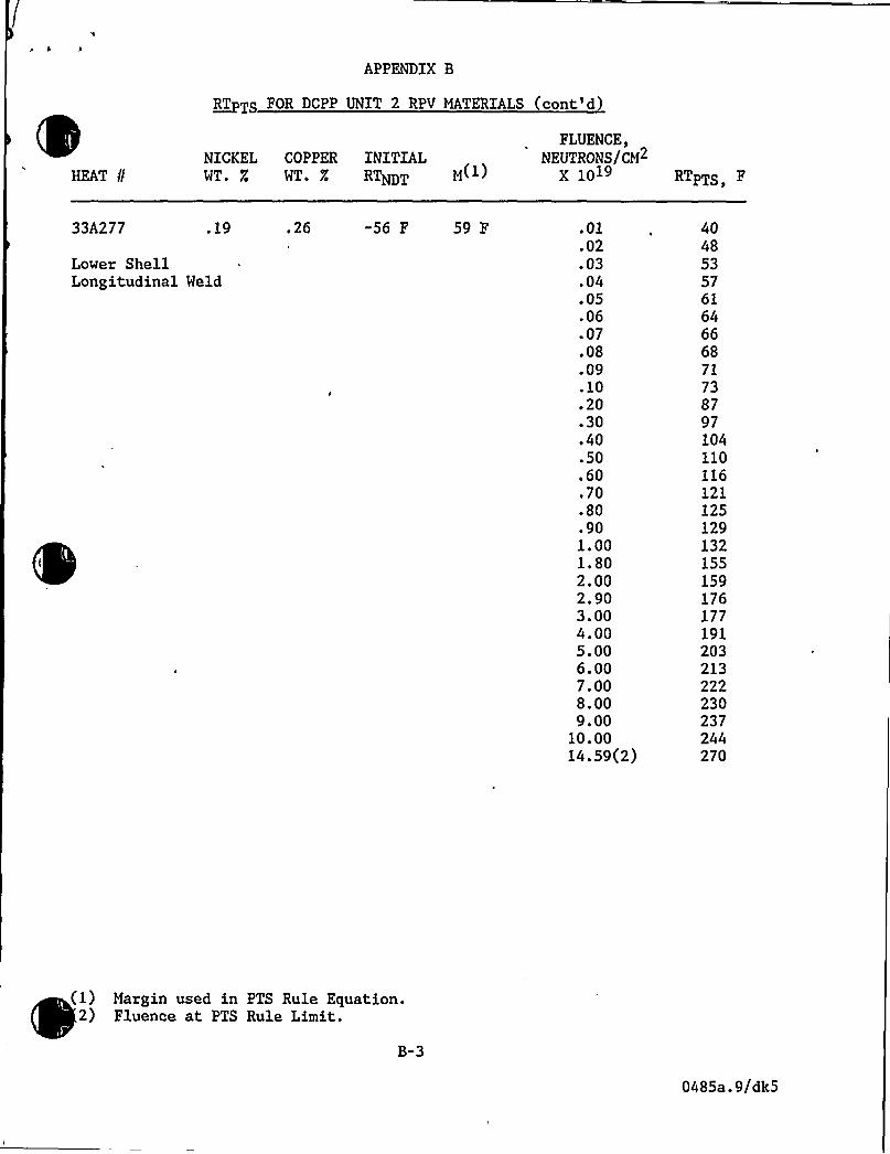
Lower ShellLongitudinal Weld
.26 -56 F 59 F .01.02.03.04.05.06.07.08.09.10.20.30.40.50.60.70.80.901.001.802.002.903.004.005.006.007.008.009.00
10.0014.59(2)
404853576164666871738797104110116121125129132155159176177191203213222230237244270
(1) Margin used in PTS Rule Equation.2) Fluence at PTS Rule Limit.
B-3
0485a.9/dk5


APPENDIX B
RT TS FOR DCPP UNIT 2 RPV MATERIALS (cont'd
HEAT 8
NICKEL COPPER INITIALWT. R WT. X RTNDT M
FLUENCE,NEUTRONS/CM2
X 10» RTPTS F
21935 .68
Upper toIntermediate ShellCircumferential Weld
.18 -56 F 59 F .01.02.03.04.05.06.07.08.09.10.20.30.40.50.60.70.80.901.001.802.002.903.004.005.006.007.008.009.00
10.0031.07(2)
37444952555860626466798895100105110114117120141145160161174184194202209216222300
(1) Margin used in PTS Rule Equation.2) Fluence at PTS Rule Limit.
B-4
0485a.9/dk5


APPENDIX B
~RT TS FOR DCPP UNIT 2 RPV MATERIALS cont'd
HEAT /INICKEL COPPER INITIALWT. Z WT. Z RTNDT M
FLUENCE,NEUTRONS/CM2
X 1019 RTPTS F
10120 .03
Intermediate toLower ShellCircumferential Weld
.04 '56 F 59 F .01.02.03.04.05.06.07.08.09.10.20.30.40.50.60.70.80.901.001.802.002.903.004.005.006.007.008.009.00
10.00)999.00(2)
101011ll111212121414151516171819192020
300
(1) Margin used in PTS Rule Equation.2) Fluence at PTS Rule Limit.
B-5
0485a.9/dk5

APPENDIX B
RT TS FOR DCPP UNIT 2 RPV MATERIALS cont'd
HEAT //NICKEL COPPER INITIALWT. X WT. g RTNDT M(
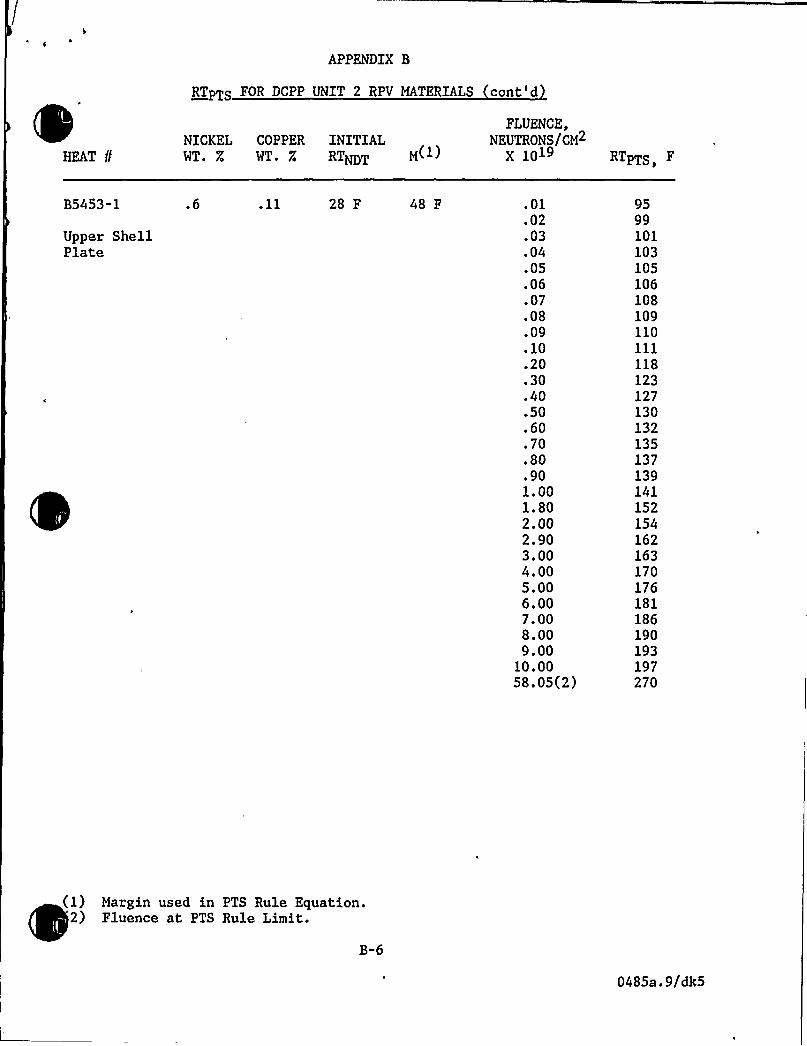
FLUENCE,NEUTRONS/CM
X 10» RTPTS,
B5453-1
Upper ShellPlate
.6 28 F 48 F .01.02.03.04.05.06.07.08.09.10.20.30.40.50.60.70.80.901.001.802.002.903.004.005.006.007.008.009.00
10.0058.05(2)
9599101103105106108109110111118123127130132135137139141152154162163170176181186190193197270
(1) Margin used in PTS Rule Equation.2) Fluence at PTS Rule Limit.
B-6
0485a.9/dk5


APPENDIX B
~RT TS FOR DCPP UNIT 2 RPV MATERIALS cont'd
HEAT 8NICKEL COPPER INITIALWT. % WT. % RTNDT M~
FLUENCE,NEUTRONS/CM2
X '10» RTPTS F
I
B5453-3
Upper„ ShellPlate
.6 59 F .01.02.03.04.05.06.07.08.09.10.20.30.40.50.60.70.80.901.001.802.002.903.004.005.006.007.008.009.00
10.00
83878991939496979899106ill11511812012312512712914014215015)158164169174178181185
(1) Margin used in PTS Rule Equation.2) Fluence at PTS Rule Limit.
B-7
0485a.9/dk5


HEAT /INICKEL COPPER INITIALWT. R WT. 7.'TNDT M~
FLUENCE,NEUTRONS/CM
X 10»
APPENDIX B
~RT TS FOR DCPP UNIT 2 RPV MATERIALS cont'd)
RTPT
B5011-1R
Upper ShellPlate
.65 0 F 59 F .Ol.02.03.04.05.06.07.08.09.10.20.30.40.50.60.70.80.901.001.802.002.903.004.005.006.007.008.009.00
10.0071.09(2)
78828587899092939495102107111114117120122124126137139148149156162167172176180183270
1) Margin used in PTS Rule Equation.2) Fluence at PTS Rule Limit.
B-8
0485a.9/dk5


APPENDIX B
~RT TS FOR DCPP UNIT 2 RPV MATERIALS (cont'd)
HEAT 8
NICKEL COPPER INITIALWT. % WT. Z RTNDT M(
FLUENCE,NEUTRONS/CM
X 1019 RTPTS
B5454-1
IntermediateShell Plate
.62 .15 52 F 48 F ~ 01.02.03.04.05.06.07.08.09.10.20.30.40.50.60.70.80.901.001.802.002.903.004.005.006.007.008.009.009.32(2)
10.00
127132136139141144145147149150160167173177181185188190193209212224225235244251257263268270273
(1) Margin used in PTS Rule Equation.2) Fluence at PTS Rule Limit.
B-9
0485a.9/dk5


APPENDIX B
~RT TS FOR DCPP UNIT 2 RPV MATERIALS (cont'd
HEAT /INICKEL COPPER INITIALWT. % WT. R RTNDT M(
FLUENCE,NEUTRONS/CM
X 10» RTPTS,
B5454-2
IntermediateShell Plate
.59 .14 67 F 48 F .01.02.03.04.05.06.07.08.09.10.20.30.40.50.60.70.80.901. 001.802.002.903.004.005.006.007.008.009.009.37(2)
10.00
139144148151153155156158159160170176181185189192195197200214217228229238246252258264268270273
(1) Margin used in PTS Rule Equation.2) Fluence at PTS Rule Limit.
B"10
0485a.9/dk5


HEAT 8
NICKEL COPPER INITIALWT. Z WT. % RTNDT M~
FLUENCE,NEUTRONS/CM2
X 10»
APPENDIX B
~RT TS FOR DCPP UNIT 2 RPV MATERIALS cont'd
RTPTS,
B5454-3
IntermediateShell Plate
.62 .15 33 F 48 F .01.02.03.04.05.06.07.08.09.10.20.30.40.50.60.70.80.901.001.802.002.903.004.005.006.007.008.009.00
10.0013.80(2)
108113l)7
„120122125126128130131141148154158162166169171174190193205206216225232238244249254270
1) Margin used in PTS Rule Equation.2) Fluence at PTS Rule Limit.
B"11
0485a.9/dk5


<o
V L
APPENDIX B
~RT TS FOR DCPP UNIT 2 RPV MATERIALS cont'd
HEAT 8NICKEL COPPER INITIALWT. Z WT. X'TNDT M
FLUENCE,NEUTRONS/CM2
X 10» RTPTS,
B5455-1
Lover ShellPlate
.56 .14 -15 F 48 F .01.02.03.04.05.06.07.08.09.10.20.30.40.50.60.70.80.901,001.802,002.903.004.005.006.007.008.009.00
10.0048.2(2)
57626568707274757678879398102106109111114l)6131133144145154162168174179184188270
(1) Margin used in PTS Rule Equation.) Fluence at PTS Rule Limit.
B"12
0485a.9/dk5


HEAT //NICKEL COPPER INITIALWT % WT R RTNDT M )
FLUENCE,NEUTRONS/CM
X 1019
APPENDIX B
~RT TS FOR DCPP UNIT 2 RPV MATERIALS cont'd
RTPTS
B5455-2
Lower ShellPlate
.56 .14 0 F 48 F .01.02.03.04.05.06.07.08.09.10.20.30.40.50.60.70.80.901.001.802.002.903.004.005.006.007.008.009.00
10.0037.83(2)
72778083858789909193102108113117121124126129131146148159160169177183189194199203270
1) Margin used in PTS Rule Equation.2) Fluence at PTS Rule Limit.
B-13
0485a.9/dk5


APPENDIX B
~RT TS FOR DCPP UNIT 2 RPV MATERIALS (cont'd)
HEAT uNICKEL COPPER INITIALWT. % WT. Z RTNDT M
FLUENCE,NEUTRONS/CM2
X 1019 RTPTS F
B5455-3
Lower ShellPlate
.62 15 F 48 F .01.02.03.04.05.06.07.08.09.10.20.30.40.50.60.70.80.901.001.802.002.903.004.005.006.007.008.009.00
10.00106.45(2)
80838688899092939495101105109112114116118120122132134141142148154158162166169172270
(1) Margin used in PTS Rule Equation.(2) Fluence at PTS Rule Limit.
B-14
0485a.9/d