Embed Size (px)
Citation preview
Los Alamos High-Energy Neutron Testing
Handbook
Steve Wender Los Alamos National Laboratory
Laura Dominik Honeywell, Inc.
Rev A LA-UR 19-30813

Los Alamos Neutron Testing Handbook
2
Los Alamos Neutron Testing Handbook
3
Prepared By
Document Owner(s) Organization
Steve Wender [email protected] LANSCE
Laura Dominik [email protected] Honeywell
Project Charter Version Control
Version Date Change Description
A 09/25/2019 Initial Release
Los Alamos Neutron Testing Handbook
4
TABLE OF CONTENTS
1 PURPOSE ................................................................................................................................ 6
1.1 Document Format ....................................................................................................... 6
1.2 Applicable Documents ................................................................................................ 6
1.3 Acronyms .................................................................................................................... 7
1.4 Definitions ................................................................................................................... 7
2 BACKGROUND ....................................................................................................................... 8
2.1 Atmospheric Neutron Environment ............................................................................. 8
2.2 High energy Single Event Effects ............................................................................... 8
2.3 Definitions ................................................................................................................... 9
3 LOS ALAMOS WEAPONS NEUTRON RESEARCH FACILITY .......................................... 10
3.1 Facility ....................................................................................................................... 10
3.2 Proposal for Beam Time ........................................................................................... 11
3.3 User Registration, Training, and Computer Usage ................................................... 12
3.4 User Agreements ...................................................................................................... 12
3.5 Shipping Information ................................................................................................. 13 3.5.1 Shipping Equipment to LANSCE ............................................................................... 13 3.5.2 Return Shipping from LANSCE: ................................................................................. 13
4 ICE HOUSE FACILITIES ....................................................................................................... 14
4.1 Beam Parameters and Acceleration Factors ............................................................ 16
4.2 Neutron Beam Dosimetry .......................................................................................... 16
4.3 Beam Calculations for ICE House I and ICE House II .............................................. 17
4.4 Description of the Run Sheet .................................................................................... 17
5 TEST PREPARATION ........................................................................................................... 20
5.1 Decisions Prior to Test .............................................................................................. 20
5.2 Testing Setup in ICE Houses .................................................................................... 20
5.3 Remote Room Requirements and Computing Rules ................................................ 20
5.4 Cameras at LANA and in the ICE Houses ................................................................ 21
5.5 Correction for Beam Divergence ............................................................................... 21
5.6 Correction for Attenuation ......................................................................................... 21
5.7 Translation Stage for Remote Positioning ................................................................ 22
5.8 Fission Count Logging .............................................................................................. 22
5.9 EMI Equipment .......................................................................................................... 22
5.10 Qualification of Equipment for Certification ............................................................... 22
6 EXPERIMENT ........................................................................................................................ 22
6.1 Safety Review ........................................................................................................... 22
Los Alamos Neutron Testing Handbook
5
6.2 Beam Rates for Experiment ...................................................................................... 23
7 POST TEST DATA ANALYSIS ............................................................................................. 23
7.1 Upset Rate Calculations ........................................................................................... 23
7.2 SEU cross section Calculation Example ................................................................... 24
8 EXAMPLE CALCULATION OF DUT UPSET RATES .......................................................... 24
8.1 Test Preparation ........................................................................................................ 25
8.2 Experiment ................................................................................................................ 26
8.3 Results ...................................................................................................................... 26
9 WORKS CITED ...................................................................................................................... 29
APPENDIX A – EXAMPLE OF PROPRIETARY USER AGREEMENT ....................................... 30
APPENDIX B – USER ORIENTATION AND CHECKLIST .......................................................... 38
APPENDIX C – NEUTRON TIME-OF-FLIGHT ............................................................................. 42 FIGURES
Figure 1 Neutron Spectrum for the ICE-II flight path (30R) at LANSCE/WNR ............................... 11 Figure 2 ICE House 1 Layout ......................................................................................................... 14 Figure 3 Photos of ICE House I Experimental Area ....................................................................... 15 Figure 4 Photos of ICE-II Experimental Area ................................................................................. 15 Figure 5 Time structure of WNR proton beam ............................................................................... 16 Figure 6 Typical Run Sheet ............................................................................................................ 19 Figure 7 SEU/Fluence in One-Hour Runs ...................................................................................... 27 TABLES Table 1 SEE Type Description ......................................................................................................... 9 Table 2 Description of SEE Fault Conditions ................................................................................. 26 Table 3 Test Results ....................................................................................................................... 27 Table 4 Example Calculation Sheet ............................................................................................... 28
Los Alamos Neutron Testing Handbook
6
1 Purpose The purpose of this document is to provide user information and guidelines for testing Integrated Circuits (IC) and electronic systems at the Irradiation of Chips and Electronics (ICE) Houses at the Los Alamos Neutron Science Center (LANSCE) at Los Alamos National Laboratory (LANL). Microelectronic technology is constantly advancing to higher density, faster devices and lower voltages. These factors may increase device susceptibility to radiation effects. The high-energy neutron source at LANSCE/LANL provides the capability for accelerated neutron testing of semiconductor devices and electronic systems in prototypical neutron environments and to simulate effects in other neutron environments.
1.1 Document Format
This handbook contains the following sections and appendices:
Section 1 is an introduction to the document, giving its scope and format.
Section 2 provides background information on the atmospheric environment and definitions of the resulting Single Event Effects (SEE).
Section 3 describes the Weapons Neutron Research (WNR) facility and the process for submitting proposals for beam time and other administrative procedures.
Section 4 describes the ICE House facilities.
Section 5 describes the test preparation steps.
Section 6 provides guidance on running the experiment.
Section 7 provides post test data analysis information and examples of how to caclulate failure rates using ICE House data.
Section 8 provides an example of calculating the fluence for a test run and analysis of results.
1.2 Applicable Documents
AUTHOR REFERENCE TITLE/CONTENT
JEDEC JESD89-3 JEDEC Standard, JESD89-3, Test Method for Beam Accelerated Soft Error Rate, September 2005.
IEC, TC 107 Working Group
IEC 62396-Part 1 Standard
Process management for avionics-Atmospheric radiation effects - Standard for the accommodation of Atmospheric Radiation Effects via Single Event Effects within Avionics Electronic Equipment, International Electrotechnical Commission, 2011.
Los Alamos Neutron Testing Handbook
7
1.3 Acronyms
DUT Device under Test
FP Fission Pulse
IC Integrated Circuit
ICE Irradiation of Chips and Electronics
IEC International Electrotechnical Commission
JEDEC Joint Electron Device Engineering Council
LANL Los Alamos National Laboratory
LANSCE Los Alamos Neutron Science Center
µP Micro Pulse
MP Macro Pulse
MBU Multiple Bit Upset
MeV Million electron volts
n Neutron
NPUA Non-Proprietary User Agreement
PAC Program Advisory Committee
PUA Proprietary User Agreement
SEE Single Event Effects
SEFI Single Event Functional Interrupt
SEU Single Event Upset
SEL Single Event Latchup
SET Single Event Transient
SR steradian
TOF Time of Flight
TS Technical Specification
TTL Transistor-to-Transistor Logic
WNR Weapons Neutron Research
1.4 Definitions
Single Event Effects encompasses all the potential effects on a semiconductor device caused by the interaction of a single particle on a semiconductor, in this case cosmic-ray induced neutrons.
Latchup a condition that causes the loss of device function or control due to a single event induced high current state; requires a re-boot for entire device (power down), or replacement of damaged hardware.
Cross Section radiation sensitivity parameter, units of cm2. Probability that 1 particle/cm2 will cause an upset. This is the number of upsets/neutron/cm2 for the system or per bit.
Fluence number of neutrons per cm2; similar to an intensity which has units per area
Flux amount of neutrons / (cm2 hr); is the number of neutrons passing thru an area per hour, a rate of flow
Count number of events observed in detector
Los Alamos Neutron Testing Handbook
8
Failure Rate failures per hour
MTBF Mean time between failures =1/Failure Rate
Neutron an elementary particle with atomic mass number of one and carries no charge. It is a constituent of every nucleus except hydrogen.
Ω solid angle of an Area at a distance L is given by: =Area/L2
2 Background
2.1 Atmospheric Neutron Environment
Cosmic radiation is constantly bombarding the earth. The composition of these cosmic rays are mostly protons and come from the sun and outside our solar system. In addition, periodic Solar Particle Events or Coronal Mass Ejections also contribute to the terrestrial cosmic-ray flux. When cosmic-ray particles penetrate the magnetic field of the earth and reach the earth’s atmosphere, they collide with nuclei in the air and create secondary radiation which leads to a flux of various energetic particles, including free neutrons. A single primary cosmic ray entering the atmosphere may create several secondary particles. Many of these have enough energy to undergo collisions and created additional secondaries of their own. Most charged particles are absorbed by the atmosphere before they reach terrestrial levels. Because neutrons are uncharged, they can travel the distances from where they were created to aircraft altitudes and below. At sea level and the altitudes flown by modern aircraft neutrons are the main area of concern and have been shown to be most responsible for causing Single Event Effects in electronics. The terrestrial radiation environment is different from the radiation environment in space where the major constituents are direct cosmic rays consisting of protons and heavy ions. The terrestrial cosmic-ray induced neutron flux varies with global position (latitude), altitude, cosmic-ray (solar and galactic) activity and even the local environment, but all terrestrial locations are exposed to this radiation. The neutron flux intensity is approximately 300 times greater where typical commercial airliners operate than at sea level. This factor of 300 and the critical requirements of their use is the major reason for the attention of the avionics industry to SEE.
2.2 High energy Single Event Effects
Single Event Effects caused by atmospheric radiation have been recognized in recent years as a design issue for aerospace and terrestrial systems. While the effects are more prevalent at altitudes where commercial airliners typically operate, radiation effects occur in electronic systems at all altitudes, including ground level. When a neutron impinges on a semiconductor device there is a probability for a nuclear reaction to occur with the material in the device. This nuclear reaction can produce one or more energetic charged particles which can deposit energy (or charge) along its path until its energy is depleted and it stops. The amount of charge / path length depends on the charge and energy of the charged particle. When this spurious charge is deposited in a sensitive volume of a semiconductor it can cause a SEE. Neutrons are different from protons because neutrons can only deposit charge by creating charged particles via nuclear reactions where protons can deposit charge directly via coulomb interactions as well as via nuclear reactions. There are several types of events which are the result of a single particle depositing sufficient charge or energy in an electronic device to cause a disturbance. These events can cause undesirable behaviors, including:
corrupted data
CPU halts and interrupts
unplanned events
transient voltages in the circuit
destruction of the device
Los Alamos Neutron Testing Handbook
9
The industry trend is for continued decreases in component feature size and operating voltages, while the number of elements in a given device continues to increase. Many component parameters are scaled as technologies are downsized: gate length, junction size, junction depth, doping concentrations, oxide thickness, and power supply voltage. As this trend continues to deep sub-micron gate lengths, component designs are achieving higher densities and lower voltages, resulting in smaller active charge regions. In general, for decreasing feature size of silicon-based cells, the expected critical charge decreases and the expected sensitivity to radiation may increase. In addition, as the sensitive volumes get closer together, a single charged particle may traverse several nodes and cause multiple SEE. Subsequently, it is expected that the SEE cross sections will continue to be impacted. In addition, the sheer number of integrated circuits are rapidly increasing and are now used in almost every aspect of modern life. The following are several reasons why the risk of SEEs in electronics systems is increasing:
1. Technology is trending towards smaller feature sizes, higher densities, and lower voltages 2. The number of memory bits and registers is greatly increasing 3. The risk of SEE is increasing for avionics equipment because the number of flights at higher altitudes is
increasing due to better efficiency and the number of polar flights (high latitude) is increasing. There are various types of failures caused by these events, but all are the result of a single particle depositing sufficient energy (or charge) to cause a disturbance in an electronic device. These events can be divided into two categories. Soft errors are upsets that just change the data, but the devices continue to operate normally. Hard errors are situations where the upset may damage the device and the device no longer operates as designed. These events include Single and Multiple Event Upsets (SEU), Single Event Latch-up (SEL), Single Event Transient (SET), Single Event Functional Interrupts (SEFI), burnout and gate rupture. Upsets can occur in both digital and analog semiconductor devices. Hardware can be damaged, as is the case of a burnout or gate rupture, but most often the failures are non-destructive. The definition of SEE encompasses all the potential effects on a semiconductor device caused by the interaction of a single energetic particle, in this case neutrons. As a specific example for the aerospace industry, for each susceptible part, an SEE sensitivity description and SEE cross section data is necessary. Details on calculating SEE rates in avionics are provided in the IEC Technical Specification IEC TS 62396-1 [1]. The cross-sectional area is a figure of merit that establishes how sensitive the component is to the effects of atmospheric radiation. The effects, such as single event upsets (SEU) or single event latch-ups (SEL), will have distinct cross sections per SEE type. To establish a normalized standardized flux for avionics calculations, IEC/TS 62396 defines the aircraft’s flux at 40,000 feet and 45o latitude as 6000 n/cm2/ hr (neutron energy > 10 MeV). This is the standard number for reference calculations. The actual neutron flux will vary depending upon altitude, latitude, solar activity and the nearby environment.
2.3 Definitions
The definitions of the SEE Types are shown in Table 1. Table 1 SEE Type Description
Term Definition
Single Event Upset
(SEU)
A change in the logic state of a storage element, i.e., memory cell.
Note: After a new write cycle, the stored data is correct.

Los Alamos Neutron Testing Handbook
10
Term Definition
Multiple Bit Upset
(MBU)
An upset to more than one bit in the same word of stored memory, caused by a single particle
Multiple Cell Upset
(MCU)
An upset of stored bits in different words, caused by a single particle.
Single Event Latchup
(SEL)
An increased current state of a device induced by a single particle and caused by the turn-on of parasitic transistors in the device. The state cannot be released until power is cycled and may or may not be destructive depending on the size and duration of the increased current flow.
Single Event Transient
(SET)
Spurious signal or voltage, induced by the deposition of charge by a single particle that can propagate through the circuit path during one clock cycle.
Single Event Functional Interrupt
(SEFI)
An upset, typically in a control path, that leads to widespread loss of functionality. These often occur in complex devices such as microprocessors.
Note: This effect has sometimes been referred to as lockup, indicating that sometimes the part can be put into a “frozen” state
Single Event Gate Rupture
(SEGR)
A state of electrical breakdown included by a single particle that results in the degradation or destruction of the gate oxide in a transistor.
Single Event Burnout
(SEB)
Avalanche breakdown induced by a single particle that results in a high current and localized heating that may result in the destruction of the device.
Single Event Hard Error (SEH)
Hard errors in devices such as memory, take the form of “stuck” bits. The error is “hard” because the device no longer functions properly, even after power reset and reinitialization.
3 Los Alamos Weapons Neutron Research Facility
3.1 Facility
The Department of Energy and the Los Alamos National Laboratory operate the LANSCE as a “Designated User Facility”. As such, scientists and engineers from all over the world can come and use these facilities. At the core of the facility is an 800 MeV proton linear accelerator. The accelerator operates in support of several national programs including Defense and Basic Science research and medical isotope production. There are two neutron sources at LANSCE: a high-energy neutron source with neutron energies from approximately 1 MeV to 600 MeV and a low-energy neutron source that produces neutrons from sub-thermal to approximately 1 MeV. Neutrons are produced when the proton beam strikes a tungsten neutron-production target. In the case of the high-energy neutron source at the WNR target area, the shape of the neutron spectrum depends on the angle between the flight path and the proton beam. The flight paths at +/- 30-degrees produce a neutron spectrum that is very similar to the spectrum of neutrons produced by cosmic rays in the atmosphere. These two flight paths called ICE House I and ICE-II are largely used for neutron radiation effects studies. In the case of the low-energy target at the Lujan Center, the flight paths view moderators so low energy neutrons are produced. In the case of the Lujan Center, the geometry of the moderators determine the shape of the neutron energy spectrum.
Los Alamos Neutron Testing Handbook
11
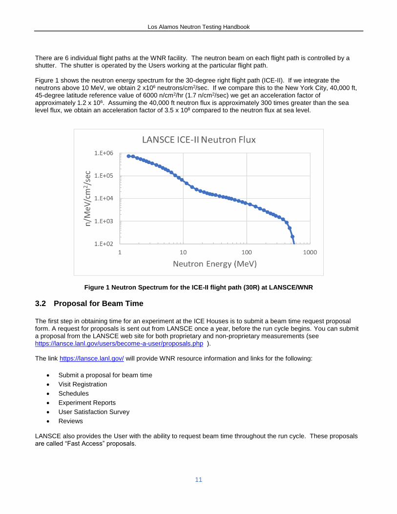
There are 6 individual flight paths at the WNR facility. The neutron beam on each flight path is controlled by a shutter. The shutter is operated by the Users working at the particular flight path. Figure 1 shows the neutron energy spectrum for the 30-degree right flight path (ICE-II). If we integrate the neutrons above 10 MeV, we obtain 2 x10⁶ neutrons/cm2/sec. If we compare this to the New York City, 40,000 ft, 45-degree latitude reference value of 6000 n/cm2/hr (1.7 n/cm2/sec) we get an acceleration factor of approximately 1.2 x 10⁶. Assuming the 40,000 ft neutron flux is approximately 300 times greater than the sea level flux, we obtain an acceleration factor of 3.5 x 10⁸ compared to the neutron flux at sea level.
Figure 1 Neutron Spectrum for the ICE-II flight path (30R) at LANSCE/WNR
3.2 Proposal for Beam Time
The first step in obtaining time for an experiment at the ICE Houses is to submit a beam time request proposal form. A request for proposals is sent out from LANSCE once a year, before the run cycle begins. You can submit a proposal from the LANSCE web site for both proprietary and non-proprietary measurements (see https://lansce.lanl.gov/users/become-a-user/proposals.php ). The link https://lansce.lanl.gov/ will provide WNR resource information and links for the following:
Submit a proposal for beam time
Visit Registration
Schedules
Experiment Reports
User Satisfaction Survey
Reviews LANSCE also provides the User with the ability to request beam time throughout the run cycle. These proposals are called “Fast Access” proposals.
Los Alamos Neutron Testing Handbook
12
All Users must submit a beam time proposal. The proposal includes information about the User (name, organization, nationality, contact information, list of team members coming to LANSCE, etc.), amount of beam time desired, preferred dates for beam time and a description of the goals and methodology of the measurement. Users from industry who want their results to be proprietary are charged for beam time and LANSCE support. This agreement is part of a “Proprietary User Agreement” (see Appendix A and section 3.4). Users from Universities are not charged but must submit their proposal to a Program Advisory Committee (PAC) for a scientific merit review. Their chances of receiving beam time depends on the rating given to their proposal by the PAC.
3.3 User Registration, Training, and Computer Usage
All experimenters visiting LANSCE must register at LANL. Registration allows the LANSCE User Office to prepare for their visit. This preparation includes obtaining approval for the visit, preparing ID badges, checking and scheduling any necessary training, preparing radiation dosimetry, and arranging gate access, computer passwords, etc. LANSCE must make special preparations for non-US citizens. If you are a foreign national, it may take up to 14 weeks to receive approvals. It is important to consider this given the tight schedules we are often given. If a user fails to register, they may not be allowed on site until the required approvals are obtained which may take several days even for US citizens. Once you register, you should receive an email informing you of your training requirements. On-site training is required for first time visitors and, if you are a return visitor, there may be periodic retraining. Prior to reporting to the LANSCE Training Office for on-site training, a badge must be obtained from the LANL Badge Office which is open on weekdays only between 7:00 am and 3:30 pm (office closed for lunch 12:00pm to 1:00pm). Day of arrival and additional information can be found here: https://lansce.lanl.gov/users/become-a-user/index.php. The LANSCE User Office will notify users what training is required and if retraining is necessary. The training can take as long as 4 hours. Review materials are available on the website. It is recommended that training be taken the day before your experiment begins. Note that LANSCE offers training on weekdays only, between 8:00 am and 1:00 pm. Verification of your training is obtained from the Training Office in the form of “green sheets” that must be presented to the instrument scientist prior to beginning the experiment. After training, users must pick up their radiation dosimetry badges from the front desk of the LANSCE Training Office. In addition to computer-based training, the flight path scientist will provide an orientation talk based on a User Checklist. The checklist is given in Appendix B. This training will include a “hands-on” demonstration of proficiency in the operation of the shutter interlock system. All Users must attend this training.
3.4 User Agreements
Every organization that uses the LANSCE facilities must have an active User Agreement between LANL and their organization. There are two kinds of agreements: A Non-Proprietary User Agreement (NPUA) and a Proprietary User Agreement (PUA). PUA’s are generally used by industry and their proposals are not subjected to a merit review by the PAC. This document spells out the agreement between the User’s institution and the Laboratory. It includes a statement of work which details the amount of beam time that will be used and the associated costs. The User will first be sent a questionnaire which is used to develop a User Agreement which must be signed by their institution. An example of a PUA is shown in Appendix A. Both the signed User Agreement and any funding must be received before the experiment can begin.
Los Alamos Neutron Testing Handbook
13
3.5 Shipping Information
3.5.1 Shipping Equipment to LANSCE
Ship equipment to LANSCE several days prior to the experiment start date to ensure that it arrives on time.
Shipping Address:
Attn: Valerie Salazar 505-667-6797 Los Alamos National Laboratory Bikini Atoll Road, SM-30 LANSCE-NS, MS H855 TA-53, Bldg.MPF-17, DP: 01U Los Alamos, New Mexico 87545, USA
To facilitate our receipt of your equipment, please e-mail Valerie Salazar ([email protected]) when you have shipped the items and include delivery method as well as the tracking number(s).
3.5.2 Return Shipping from LANSCE:
Parts that have been in the neutron beam may become radioactive. Any irradiated equipment must be left at LANSCE until the radiation has a chance to decay or, if still activated, it can be shipped as radioactive material contingent on the User being licensed to receive the material. This means that your experimental equipment may stay at LANSCE for several weeks after your experiment is completed. The time for the equipment to decay is difficult to predict because it depends on the length of time the material has been in the beam and the type and amount of material that was put in the beam. At the end of the experiment, those items that have not been in the beam area or those items that have been in the beam area and have been surveyed and met the “no detectable activity” (NDA) limit can be released and returned. The users can then pack released equipment in their packing boxes. The Users can then:
1. Take the released equipment with them 2. Take the released equipment to a commercial shipping company (UPEX or Aspen in Los Alamos) for
shipment 3. Arrange for UPS/FedEx shipment of released equipment
a. Provide pre-printed label from UPS/FedEx. This label contains company address, phone numbers, account number, etc.
b. Pre-printed label address should be from their company and not LANL c. We will take the equipment to UPS/FedEx d. Equipment must be hand carryable.
4. Request that LANL ship the equipment. In this case the following information must be provided: a. Delivery address, person who receives items, phone numbers, etc. b. Account number of shipper c. List of items to be shipped. Include SDS sheets if applicable d. If there are lithium-ion batteries in the shipment (including laptops).
i. Laptops must be packed on top; they will need to be inspected before being shipped ii. We will fill out Department of Transportation (DOT) form for shipping approval iii. It is recommended to avoid shipping laptops in order to avoid these issues
When the activated parts are NDA, they will be returned using method 3 or 4 above. Shipments going outside the US will require additional documentation. Contact Valerie Salazar ([email protected]) for more information.
Los Alamos Neutron Testing Handbook
14
4 ICE House Facilities
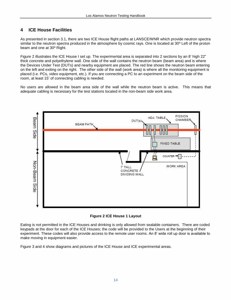
As presented in section 3.1, there are two ICE House flight paths at LANSCE/WNR which provide neutron spectra similar to the neutron spectra produced in the atmosphere by cosmic rays. One is located at 30º Left of the proton beam and one at 30º Right. Figure 2 illustrates the ICE House I set up. The experimental area is separated into 2 sections by an 8’ high 22” thick concrete and polyethylene wall. One side of the wall contains the neutron beam (beam area) and is where the Devices Under Test (DUTs) and nearby equipment are placed. The red line shows the neutron beam entering on the left and exiting on the right. The other side of the wall (work area) is where all the monitoring equipment is placed (i.e. PCs, video equipment, etc.). If you are connecting a PC to an experiment on the beam side of the room, at least 15’ of connecting cabling is needed. No users are allowed in the beam area side of the wall while the neutron beam is active. This means that adequate cabling is necessary for the test stations located in the non-beam side work area.
Figure 2 ICE House 1 Layout
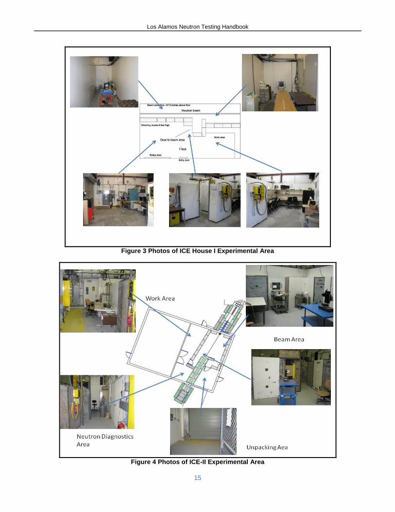
Eating is not permitted in the ICE Houses and drinking is only allowed from sealable containers. There are coded keypads at the door for each of the ICE Houses; the code will be provided to the Users at the beginning of their experiment. These codes will also provide access to the remote user rooms. An 8’ wide roll up door is available to make moving in equipment easier. Figure 3 and 4 show diagrams and pictures of the ICE House and ICE experimental areas.
Los Alamos Neutron Testing Handbook
15
Figure 3 Photos of ICE House I Experimental Area
Figure 4 Photos of ICE-II Experimental Area
Los Alamos Neutron Testing Handbook
16
4.1 Beam Parameters and Acceleration Factors
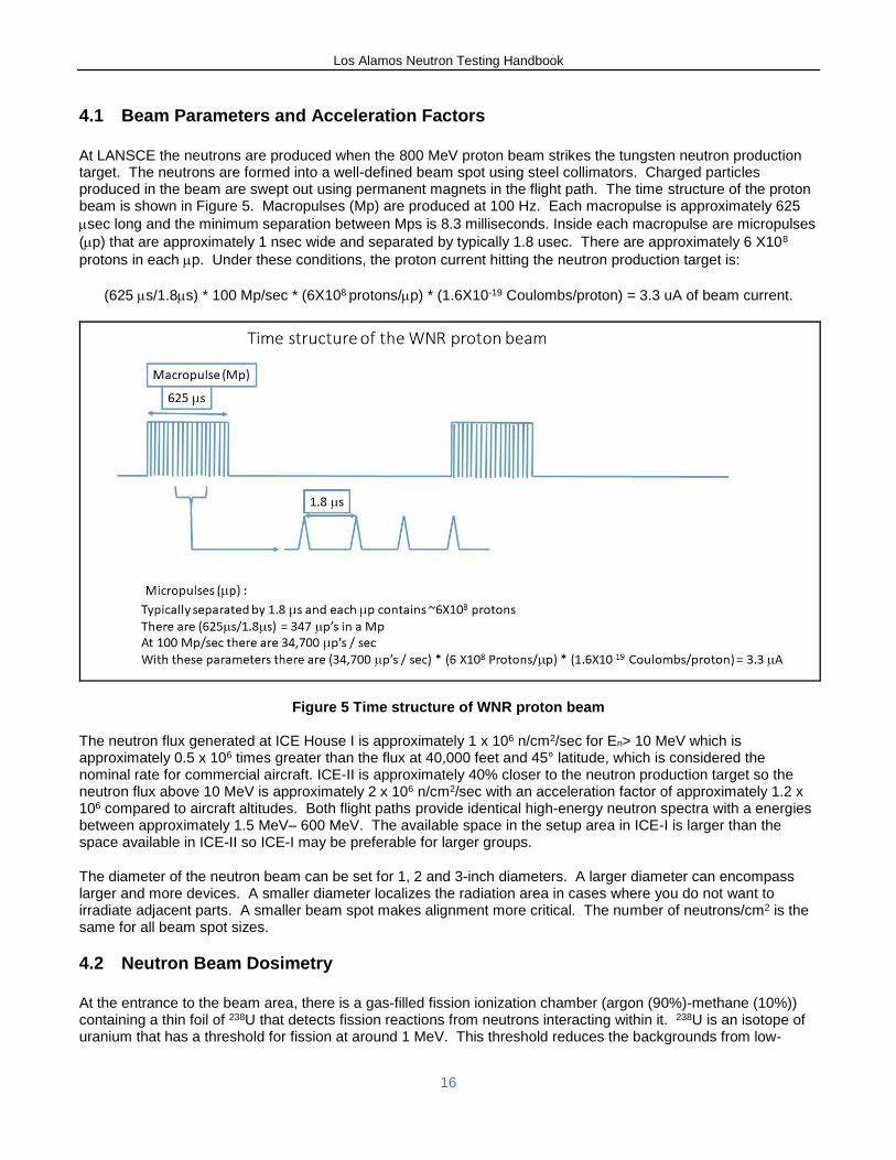
At LANSCE the neutrons are produced when the 800 MeV proton beam strikes the tungsten neutron production target. The neutrons are formed into a well-defined beam spot using steel collimators. Charged particles produced in the beam are swept out using permanent magnets in the flight path. The time structure of the proton beam is shown in Figure 5. Macropulses (Mp) are produced at 100 Hz. Each macropulse is approximately 625
sec long and the minimum separation between Mps is 8.3 milliseconds. Inside each macropulse are micropulses
(p) that are approximately 1 nsec wide and separated by typically 1.8 usec. There are approximately 6 X10⁸
protons in each p. Under these conditions, the proton current hitting the neutron production target is:
(625 s/1.8s) * 100 Mp/sec * (6X10⁸ protons/p) * (1.6X10⁻¹⁹ Coulombs/proton) = 3.3 uA of beam current.
Figure 5 Time structure of WNR proton beam The neutron flux generated at ICE House I is approximately 1 x 10⁶ n/cm2/sec for En> 10 MeV which is approximately 0.5 x 10⁶ times greater than the flux at 40,000 feet and 45° latitude, which is considered the nominal rate for commercial aircraft. ICE-II is approximately 40% closer to the neutron production target so the neutron flux above 10 MeV is approximately 2 x 10⁶ n/cm2/sec with an acceleration factor of approximately 1.2 x 10⁶ compared to aircraft altitudes. Both flight paths provide identical high-energy neutron spectra with a energies between approximately 1.5 MeV– 600 MeV. The available space in the setup area in ICE-I is larger than the space available in ICE-II so ICE-I may be preferable for larger groups.
The diameter of the neutron beam can be set for 1, 2 and 3-inch diameters. A larger diameter can encompass larger and more devices. A smaller diameter localizes the radiation area in cases where you do not want to irradiate adjacent parts. A smaller beam spot makes alignment more critical. The number of neutrons/cm2 is the same for all beam spot sizes.
4.2 Neutron Beam Dosimetry
At the entrance to the beam area, there is a gas-filled fission ionization chamber (argon (90%)-methane (10%)) containing a thin foil of 238U that detects fission reactions from neutrons interacting within it. 238U is an isotope of uranium that has a threshold for fission at around 1 MeV. This threshold reduces the backgrounds from low-
Los Alamos Neutron Testing Handbook
17
energy neutrons. A fission will occur once for a given number of neutrons passing through the chamber. Each time a fission occurs, a counter will increment, thus giving us an accurate way to measure the neutron dosage during a given experiment. This chamber is operated in a Time-of-Flight mode (see appendix C) so the shape of the neutron spectrum is also measured. The operation of the fission ionization chamber is described in the literature referenced in Section 9, item [3].
4.3 Beam Calculations for ICE House I and ICE House II
The neutron intensity is calculated the same way for both ICE House I and ICE-II flight paths. LANL staff will measure the neutron spectrum using the fission ionization chamber and Time-of-Flight techniques (See Appendix C). While data on the spectrum is being acquired, a Transistor-Transistor Logic (TTL) pulse is generated for every fission event and input into a “Fission Pulse” (FP) counter. This counter can be seen and reset to zero by the Users. This pulse is also available to Users if they want to count it as part of their data stream. At least once a day, or more frequently if necessary, the conversion factor between the FP count and the number of neutrons / cm2 is calculated and given to the Users on the Run Sheet. We generate a run sheet and provide it to the Users both on paper and, at the end of the experiment, electronically as an EXCEL spreadsheet. Figure 6 shows a typical run sheet. This run sheet is also used as part of the example in Section 8. It is the responsibility of the Users to keep track of the FP count during their measurements. To keep track of the number of FP, the user must either reset the counter to zero for each measurement or note the beginning count at the start of the measurement and subtract it from the final value at the end of the measurement. The FP counter displays a number which can be recorded. This counter is also available in the remote data rooms using a simple USB counter and accessing it from the remote data room over the Ethernet cable. In a typical measurement, the User records the number of upsets in a DUT and the FP counter value during that measurement. The FP is then converted to the number of neutrons / cm2 using the given conversion factor. The number of upsets /neutron/cm2
is obtained by dividing the number upsets by the number of neutrons/cm2. For example, if the conversion factor is 81512 neutrons/cm2/FP (for neutrons above 10 MeV), and if there were 1000 upsets during the test of 5000 FP counts, then there are:
[# of upsets / FP] / [# of neutrons /cm2/FP] = [1000 upsets / 5000 fission pulse] / [81512 neutrons /cm2/ FP] = 2.45 X 10⁻⁶ upsets / neutrons /cm2 (En>10 MeV).
A new calculation of the conversion factor must be made when changing spot sizes.
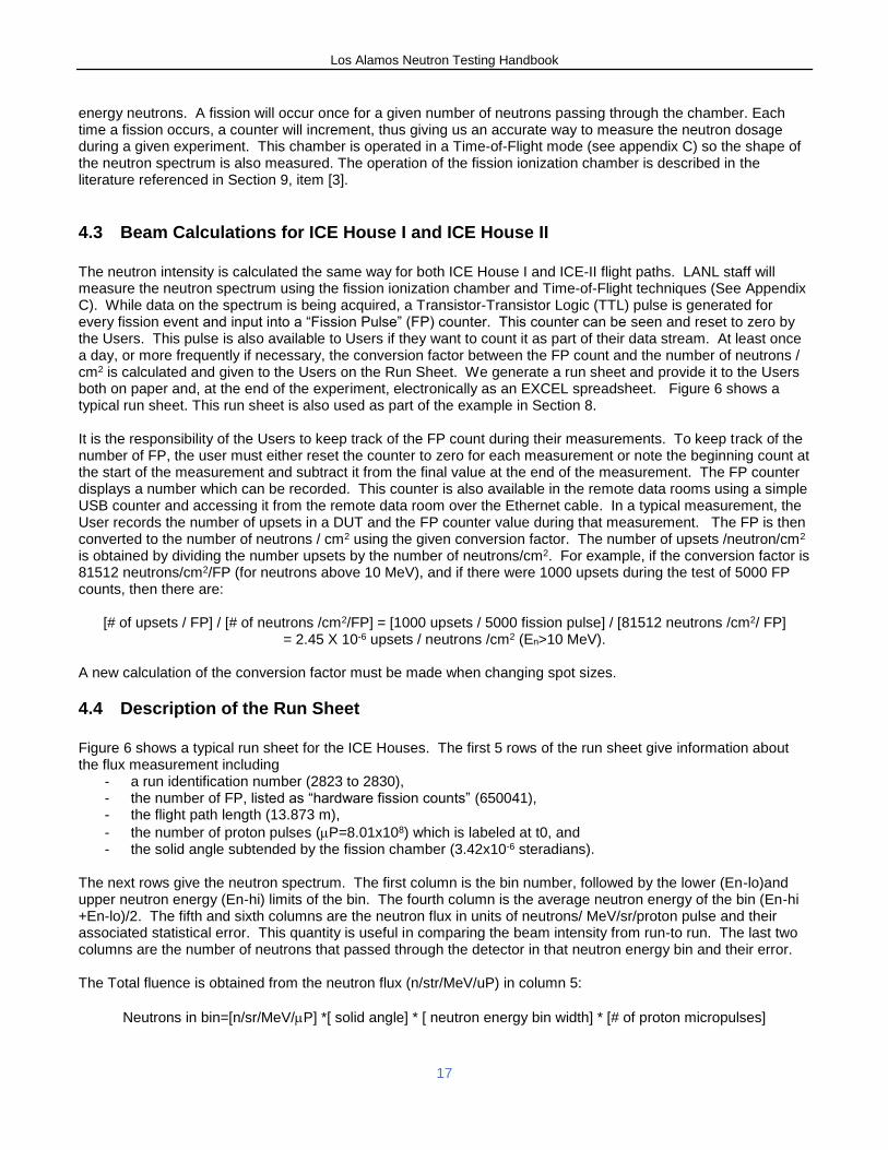
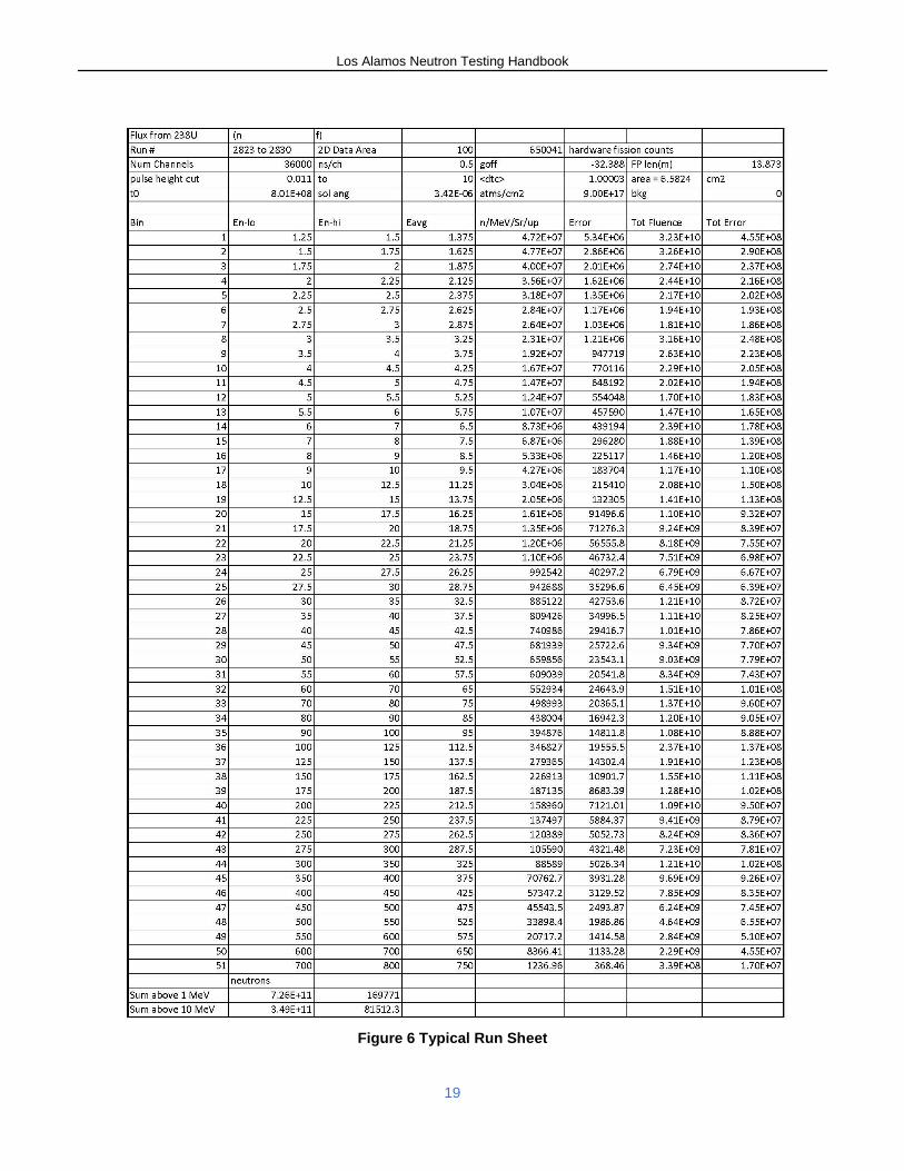
4.4 Description of the Run Sheet
Figure 6 shows a typical run sheet for the ICE Houses. The first 5 rows of the run sheet give information about the flux measurement including
- a run identification number (2823 to 2830), - the number of FP, listed as “hardware fission counts” (650041), - the flight path length (13.873 m),
- the number of proton pulses (P=8.01x10⁸) which is labeled at t0, and - the solid angle subtended by the fission chamber (3.42x10⁻⁶ steradians).
The next rows give the neutron spectrum. The first column is the bin number, followed by the lower (En-lo)and upper neutron energy (En-hi) limits of the bin. The fourth column is the average neutron energy of the bin (En-hi +En-lo)/2. The fifth and sixth columns are the neutron flux in units of neutrons/ MeV/sr/proton pulse and their associated statistical error. This quantity is useful in comparing the beam intensity from run-to run. The last two columns are the number of neutrons that passed through the detector in that neutron energy bin and their error. The Total fluence is obtained from the neutron flux (n/str/MeV/uP) in column 5:
Neutrons in bin=[n/sr/MeV/P] *[ solid angle] * [ neutron energy bin width] * [# of proton micropulses]
Los Alamos Neutron Testing Handbook
18
The solid angle in steradians is given in the run sheet as well as the number of proton micropulses (p) which is labeled at t0 on the run sheet. For example, in bin 1 the neutron fluence in the neutron energy range from 1.25 to 1.5 MeV can be calculated as:
Neutrons in bin= (# of neutrons/sr/MeV/p)* Ω *E* # of p
Where the number of neutrons/sr/MeV/p is given in column five, the solid angle is given in the fifth row, Delta-E
is the energy width of the bin = (En-hi) – (En-lo) and the number of p is in row five labeled as t0. We substitute these numbers and get:
neutrons in bin=(4.72x10⁷n/str/MeV/up) *(3.42 x 10⁻⁶ str) *(1.5-1.25 MeV) *(8.01 x 10⁸uP) =3.23x10¹⁰ neutrons, which is the number in the Total fluence column.
The diameter and area of the beam spot can be obtained from the solid angle () and the flight path length (L),
=Area/L2. In this case the solid angle is 3.42x10⁻⁶ steradians and the flight path length is 1387.3 cm. The area of the beam spot is 6.58 cm2 and the diameter of the spot is 2.89 cm (assuming a circular beam spot) or the nominal one-inch diameter spot size. The conversion factor between FP and neutrons / cm2, is given by
Sum of neutrons / # of fission pulses (FP) / area of beam spot The sum of neutrons is obtained by summing the Fluence column over neutron energy range of interest (for example neutrons above 10 MeV). That number is given at the bottom of the chart as 3.49x10¹¹. If you divide that number by the number of FP given at the top of the chart as 650041 and divide by the area of the beam spot, you get the number to the right (81512) which is the conversion factor of neutrons/cm2/FP.
Los Alamos Neutron Testing Handbook
19
Figure 6 Typical Run Sheet
Los Alamos Neutron Testing Handbook
20
5 Test Preparation
5.1 Decisions Prior to Test
Determine what spot size to be used: 1”, 2”, or 3” diameter. The number of neutrons/cm2/s on the DUT does not depend on the spot size.
Determine a schedule for how often the beam will be turned off/on. Example schedule: o First day – beam shut off at will o Second day – once every 4 hours if required o Third day – no shut down o Nights – continuous beam on
Develop a baseline schedule; identify how much time will be required for device testing.
Bring spare hardware if possible; time at Los Alamos is limited and backups are beneficial.
Determine if temperature testing will be performed.
Determine if cooling is required. There is no requirement that an experimenter be present at LANSCE during the run. However, if there is some problem with the experiment, data may be lost if no one is there to correct the problem.
5.2 Testing Setup in ICE Houses
Multiple boards can be set up in the beam. There are practical limits to the number of boards that can be put in a row and tested at one time (see section 5.6). Prior to the installation of the test equipment in the neutron beam flight path, the diameter of the beam spot is defined. The LANSCE flight path scientist will insert approximately 1 m of steel collimation in the beam path which determines the beam spot size.
Marks were placed on the wall at the front and back of the facility to align the laser beam. The crosshair laser can be aligned to these survey marks on the wall and the crosshairs are used to position the DUT. The alignment laser beam is mounted on a multi-axis precision platform to position the laser and so the laser can be rotated out of the neutron beam flight path during beam operation. When the test object alignment is required the laser is rotated back into the flight path and aligned with the previously established reference marks on the facility wall. A button near the DUT turns the alignment laser on and off.
After all test articles are placed on the test bench and connected to their respective support equipment they are aligned with the laser beam one at a time, progressing from the front to the back of the test bench. If a disturbance is suspected, the test articles are moved to the side and the alignment process is repeated.
5.3 Remote Data Room Requirements and Computing Rules
Separate remote monitoring rooms are available to Users for both ICE Houses and are located in building MPF-7. This area also contains the restrooms, couches, microwave ovens, a TV, and refrigerators. Eating is permitted in this area. Currently an Ethernet cable and a 24-port switch connects the remote data rooms with each experimental area in ICE house and ICE-II. LANSCE encourages people to use this room for their comfort and to reduce radiation doses. Los Alamos computers are available in each remote data room that can be used to communicate with User computers in the experimental areas. If the remote room will be used, determine additional experiment requirements such as:
Networking design
Additional computers/monitors
Remote reset capability
Los Alamos Neutron Testing Handbook
21
There are two approaches to controlling the test computers from the remote data rooms: 1. Using remote desktop software which is part of the PC operating systems 2. Using remote KVM (keyboard, video, mouse) connections.
Personal User computers are allowed on the Visitor Network with assigned passwords that are given out during the check in process. This will allow you access to the internet. Use of the internet should be restricted to work-related activities and incidental use such as checking flights, weather, news, etc. You are not allowed to use the visitor network to view adult sites, run a business, or gamble. Personal computers can be used to acquire data from tests. LANSCE provides computers in the remote data rooms that can communicate with User computers in the experimental areas; these computers can be used to connect to the visitor network for internet access.
5.4 Cameras at LANL and in the ICE Houses
A surveillance camera is available to observe the experiment in the beam area from outside the beam area. The camera can be focused, panned, and zoomed remotely. In addition, it can be viewed and operated from the remote data rooms. Use of personal cameras is not permitted anywhere on LANL property, including the ICE House experimental areas. This includes cell phone cameras. A government camera is provided to take pictures of the experiment. At the end of the run, the pictures are downloaded from the camera, reviewed, and transferred to the Users.
5.5 Correction for Beam Divergence
When evaluating data, a correction to the neutron flux must be made because of the divergence of the beam along the flight path. Due to the neutron beam divergence, the number of neutrons / cm2 decreases as you increase the distance of the DUT along the flight path. The correction factor is equal to the square of the ratio of the distance from the source-to-fission chamber divided by the distance of the source-to-DUT. The distance from the source to fission chamber for the ICE House I is 1996.87cm and for ICE-II is 1387.3 cm. Be sure to measure distance from each of your boards to the center of fission chamber. This correction factor will be applied to the flux in the analysis of the results. For example, if a DUT is placed 2 m beyond the fission chamber in ICE-II the divergence of the neutron beam causes the neutron flux at the DUT to be reduced by
[distance from the source-to-fission chamber / distance of the source-to-DUT]2 =
[13.87/ (13.87+2)]2= 0.76, which means the beam intensity is reduced by 24%
5.6 Correction for Attenuation
In addition to the reduction of intensity due to the divergence of the neutron beam, the neutron flux is also lost by transmission through boards and devices. The attenuation of the neutron flux is difficult to calculate because it depends on the type and amount of material placed in the beam. The attenuation also depends on the neutron energy, with lower energy neutron being attenuated more than the higher energy neutrons. For simple thin boards, a few percent of the beam is lost traversing a single board. We are currently developing a system to measure the energy dependence of the flux attenuation passing through boards. This measurement will involve measuring the transmission with and without the board. Once the energy dependent attenuation for a single board has been determined, it is possible to determine the attenuation through multiple identical boards.
The attenuation through N identical boards at a particular neutron energy is given by I(En)/Io(En) =e-NEn where
I(En) is the attenuated neutron intensity and Io(En)is the transmitted neutron intensity with no boards in the beam.
If we measure I/Io(En)for a single board, (En) is given by ln(I/Io) at En. For N boards (I/Io) =e-NEn.
Los Alamos Neutron Testing Handbook
22
For example, if we measure the transmission through a single board to be 96% or a 4% loss of neutrons at a
particular neutron energy (En). En = -ln (.96) = 0.04 If we place 8 identical boards in the beam, we get a
transmission of e-8*.04 = 0.73 or a 27% loss of neutrons at that neutron energy.
5.7 Translation Stage for Remote Positioning
We have installed a translation stage in both ICE Houses to allow remote positioning of devices in the beam. This translation stage can be controlled from outside the beam area and from the remote data room. The stage can be positioned, and the positions can be remembered and returned to that position. Use of this stage is particularly beneficial when the part must be taken out of the beam frequently and saves the time required to close and open the shutter and reduces wear on the shutter. It should be noted that the beam is still on while the parts are moving.
5.8 Fission Count Logging
A simple data logging program is available that logs the fission pulses (FPs) in 1 or 10 second time bins during the experiment. The program provides the number of FP per time bin, the time history of the fission counts, the integrated FP over the course of the measurement, and the time history of the integrated FPs. This data logging program is controlled by the Users and is available in electronic form as an EXCEL spreadsheet. This program can be viewed and operated from the remote data room.
5.9 EMI Equipment
The humidity at Los Alamos tends to be low so the possibility of static build-up is possible. To minimize the risk of static discharges, we provide anti-static mats to work on and anti-static mats on the floor of the beam areas. This equipment is available should the Users want to use them.
5.10 Qualification of Equipment for Certification
The accuracy of the neutron dosimetry depends on knowing the size of the beam spot and the distance from the production target. To get the absolute intensity of the neutron beam we also need to know the thickness of the 238U foil. The thickness of the foil was given by the manufacturer. Relative measurements should be very precise because these numbers will not change. We measure the beam spot size and uniformity at the beginning of each run cycle. The diameter of the beam spot is necessary to calculate the neutron flux. Knowledge of the uniformity of the beam spot is also necessary to accurately measure the upset rate. The uniformity of the beam is measured using image plates which can be scanned and digital images produced. The flux is measured and compared to previous years’ operation. Typically, the calibration constant does not change more than ~5% during the run. The statistical precision is mostly determined by the number of failures recorded. The statistical uncertainty in the number of n measured fails is given by the square root of n.
6 Experiment
6.1 Safety Review
Each experiment is reviewed for safety prior to being run at LANSCE. Specific information about each experiment is provided by the User as part of the proposal process. In general, placing devices on circuit boards in the beam is considered within normal operating conditions and no special safety precautions are required. However, if the test involves non-standard operating conditions, such as exposed voltages above 50 V, heating of parts, non-UL listed equipment, wireless communications, etc., the experiment will be evaluated for the particular hazard. If there are any questions, the experimenter should consult with the flight path scientist before arrival.
Los Alamos Neutron Testing Handbook
23
6.2 Beam Rates for Experiment
Integral fluence is provided for each run and is given for neutrons with energy greater than 10Mev and for neutrons with energy greater than 1.5 MeV, although any energy range can also be calculated. The real-time status of the proton beam is available to the User at lansce.lanl.gov (click “Beam status” at the top of the page). In addition, the fission pulse counter is recorded in 1 or 10 second intervals and is available to the Users.
7 Post Test Data Analysis
7.1 Upset Rate Calculations
The number of upsets for a given neutron fluence can be expressed as a convolution of the flux and a cross section:
# of Upsets = nndn
Where we have separated the problem into a cross section, which depends on the neutron energy and is a
characteristic of the device, and an energy-dependent flux, which is a property of the environment outside
the device. At this time there are no models that can reliably predict the upset cross section, so it must be measured. The neutron flux depends on the altitude, latitude, cosmic-ray activity and the local environment. The purpose of a neutron radiation experiment is to measure the cross section of the device under test and use that cross section to predict the behavior of that device in another radiation environment. Since the shape of the neutron spectrum at the ICE Houses is very similar to the shape of the cosmic-ray induced neutron spectrum, the upset rate in a given environment, X, can be obtained by scaling the ICE House results.
# Upsets in ICE House = < see> *< in ICE House>
# Upsets in X =<see > *< in X>
Or # Upsets in X ~ [# Upsets in ICE House] * [< in X> / < in ICE House>]
It should be pointed out that in the ratio [< in X> / < in ICE House>], the fluxes must be taken over the same
energy range in each case. For example, the energy range in both cases may be neutrons greater than 10 MeV. In addition, the beam at the ICE Houses expose the parts to neutrons down to 1 MeV. To the extent that the cosmic-ray neutron flux is similar in shape to the ICE House flux, that ratio should be the same. The upset cross section may be calculated using the results of an ICE House measurement using the following formula:
σsee = number of Upsets / # of neutrons/cm2.
Where see is the upset cross section for the device or per bit. The number of upsets is the corresponding number of upsets per device or upsets per bit. The number of neutrons/cm2 is obtained from the run sheet described in section 4.4.
Los Alamos Neutron Testing Handbook
24
7.2 SEU cross section Calculation Example
In this example a calculation of the SEU cross-section are based on measurements at the ICE-II. Test set up and parameters:
DUT is a single 4 Mbit SRAM and is being tested for SEU.
The device is run in the 3 cm (1 inch) diameter beam at a distance of 2 m from the center of the fission chamber in ICE-II at LANSCE.
The measurement is taken for a total of 50,000 fission pulses (FP) and 22 upsets are recorded.
The conversion factor given on the run sheet shown is 81512 n/cm2/FP for neutron energies above 10
MeV. Cross section calculations:
1. Determine neutron fluence; which = [# of FP] * [conversion factor] * [beam dispersion factor]
Fluence = [50,000FP] * [81512 n/cm2/FP] * [13.873/ (13.873+2)]2 = 3.1 x 10⁹ n/cm2 for En > 10
2. Calculate SEU cross section per device:
# Upsets in X =<see > *< in X>
Applying the above equation yields an SEU cross-section for the SRAM of
<10MeV> = 22 Upsets/ 3.1x10⁹ n/cm2= 7.1x10⁻⁹ cm
2 for neutron energies of 10 MeV and above.
The Run Sheet is described in section 4.4. The information of interest from the Run Sheet is the second number provided in the row labeled “Sum above 10 MeV”. This number is 81512.3 which is the number of neutrons/cm2 whose energy is above 10 MeV per fission pulse (FP). This information is used in the “neutron/cm2/count” column in Table 2.
SRAM DUT has 4 MBits (= 4.2x106 bits) in the device
cross section/bit = 1.7x10⁻¹⁵ (n > 10 MeV) Calculations for Failure Rate and mean time between failures (MTBF):
1. At 40000 ft, 45o latitude, the flux is 6000 n/cm2/hr, = 1.7n/cm2/s (n > 10 MeV)
2. Failure Rate/device = [Cross Section] *[Flux] = [7.1x10⁻⁹ cm2] *[1.7 n/cm2/s] =1.2x10⁻⁸ upsets/device/sec
3. Failure rate / bit= [failure rate/device] / [# of bits] =1.2x10⁻⁸/4.2x106 = 2.9 x 10⁻¹⁵ upsets/bit/sec
4. MTBF/ device=1/failure rate=[1/1.2x10-8] = 8.3x10⁷ sec =23150 hours/ device
5. MTBF/bit= [MTBF/device] * [# of bits] = [23150 h/dev] *[4.2x10⁶] =9.7x10¹⁰ hours/bit
8 Example Calculation of DUT Upset Rates The purpose of this example is to demonstrate how to use the information provided by the ICE House instrument scientists and the test data to obtain DUT upset rates. The example steps through the process for a 20-hour test
Los Alamos Neutron Testing Handbook
25
window. The example will list the steps to be taken by the user to use the experiment information to calculate the cross-section rates of the DUT, a memory device. The objective of the experiment is to measure the various types of SEE applicable to this memory device. The types of SEE measured for the DUT are SEU, MBU, SEFI, and SEL. This example assumes that the User does not have access to the internal design of the DUT, which means the SEU and MBU rates can be calculated at the bit level, but the SEFI and SEL rates can only be calculated at the device level. Testing of components and equipment for use in the atmospheric radiation environment requires the use of a high-energy neutron beam. The JEDEC Standard, JESD89-3 “Test Method for Beam Accelerated Soft Error Rate”, provides an outline of the test method and set up for radiation testing. This guideline provides procedures, stress conditions, and a minimum test sequence. [2] The test was conducted through a series of beam exposure runs. Each run was set for a duration of one hour. The experiment ran for a total of 20 one-hour runs. For the full duration of the experiment records were kept and real time observations noted. The one-hour runs were chosen to manage the large amount of test data recorded. This example is not intended to represent the full experiment time-frame of all SEE measurements.
8.1 Test Preparation
Shown below are test setup development tasks taken for experiment preparation.
Decision was made to use the 1” beam.
Custom cables were developed connecting equipment, laptops, and power supplies, taking into consideration the 8’ wall between the beam and user sides of the ICE House.
Capability was developed to remotely reset and power cycle the DUT during experiment.
Considerations were made to ensure no extraneous metal was in the path of the beam to avoid unwanted attenuation of the beam. This means items such as the chassis or heat sinks were not in the beam path.
The DUT was placed perpendicular to the beam.
The test setup employed a test controller board with an Ethernet interface for communication to the test laptop.
Test design ensured all recorded data was time-stamped.
Account for dispersion from the distance from the beam:
a. Measure the distance from the middle of the fission counter to the DUT.
b. Using the flight path length and the distance of the DUT from the middle of the fission counter, calculate the beam divergence correction factor using the equation in section 5.5
i. The flight path length is provided in the run sheet identified by the “flight path length”. In this example, the experiment is conducted in ICE House II and the flight path length from the neutron production target to the fission chamber is 13.873 m. ICE House I has a flight path length of 19.97 m. This value is used in the distance correction factor calculation.
The FP counter is available in the ICE Houses or remote user rooms. This counts the TTL pulses from the DAQ electronics. As described in section 4.3, this information is recorded at the beginning and end of each run and is used in the “Start Count” and “End Count” columns in Table 4.
Los Alamos Neutron Testing Handbook
26
8.2 Experiment
At the start of the experiment the following data was recorded:
Test article serial numbers,
Test program and/or pattern used during exposure,
Test article supply voltages applied during exposure,
Test article temperature, if other than ambient,
Article placement in the beam, including distance from the beam source. For each test run the following information was recorded:
Exposure run number,
Date and time at start of exposure run,
Exposure duration and counts,
Number and type of SEEs observed during exposure,
Potentially destructive SEE observations (if applicable),
Current levels for any SELs observed,
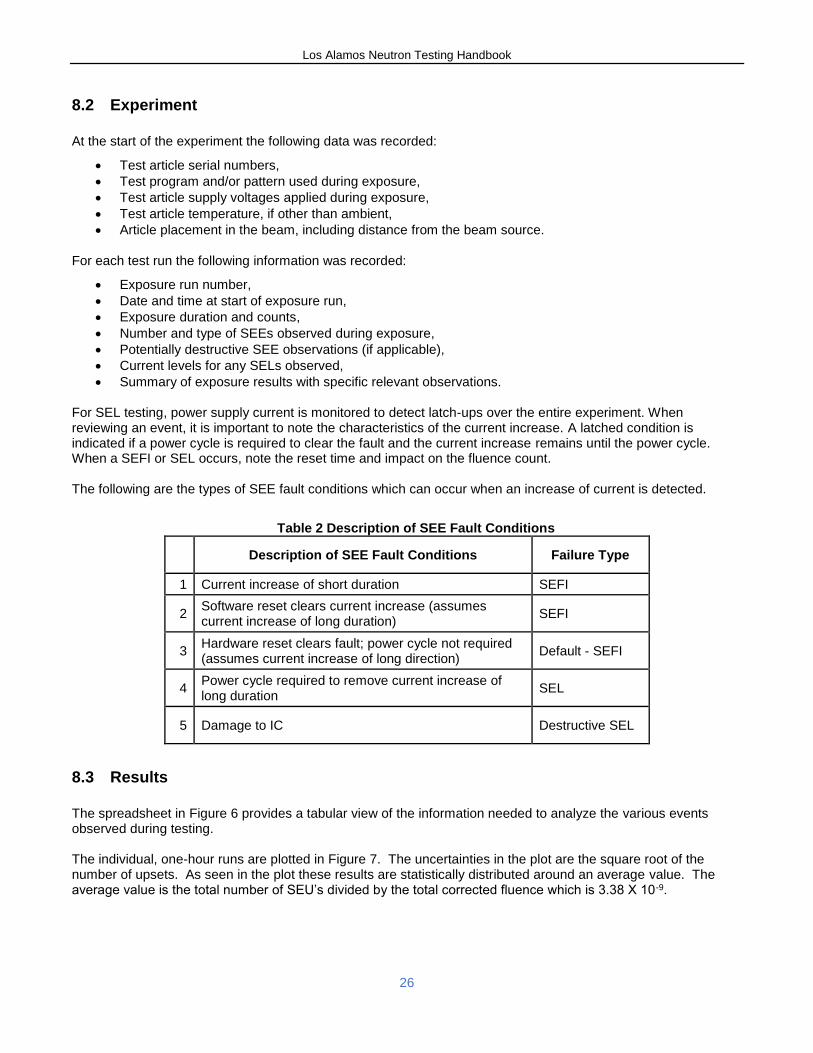
Summary of exposure results with specific relevant observations. For SEL testing, power supply current is monitored to detect latch-ups over the entire experiment. When reviewing an event, it is important to note the characteristics of the current increase. A latched condition is indicated if a power cycle is required to clear the fault and the current increase remains until the power cycle. When a SEFI or SEL occurs, note the reset time and impact on the fluence count. The following are the types of SEE fault conditions which can occur when an increase of current is detected.
Table 2 Description of SEE Fault Conditions
Description of SEE Fault Conditions Failure Type
1 Current increase of short duration SEFI
2 Software reset clears current increase (assumes current increase of long duration)
SEFI
3 Hardware reset clears fault; power cycle not required (assumes current increase of long direction)
Default - SEFI
4 Power cycle required to remove current increase of long duration
SEL
5 Damage to IC Destructive SEL
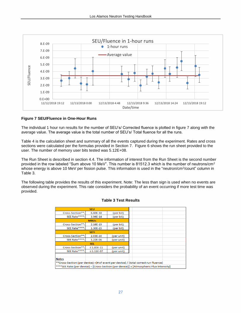
8.3 Results
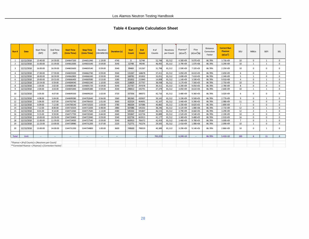
The spreadsheet in Figure 6 provides a tabular view of the information needed to analyze the various events observed during testing. The individual, one-hour runs are plotted in Figure 7. The uncertainties in the plot are the square root of the number of upsets. As seen in the plot these results are statistically distributed around an average value. The average value is the total number of SEU’s divided by the total corrected fluence which is 3.38 X 10⁻⁹.
Los Alamos Neutron Testing Handbook
27
0.E+00
1.E-09
2.E-09
3.E-09
4.E-09
5.E-09
6.E-09
7.E-09
8.E-09
12/12/2018 19:12 12/13/2018 0:00 12/13/2018 4:48 12/13/2018 9:36 12/13/2018 14:24 12/13/2018 19:12
SEU
/Flu
ence
Date/time
SEU/Fluence in 1-hour runs1-hour runs
Average value
Figure 7 SEU/Fluence in One-Hour Runs The individual 1 hour run results for the number of SEU’s/ Corrected fluence is plotted in figure 7 along with the average value. The average value is the total number of SEU’s/ Total fluence for all the runs. Table 4 is the calculation sheet and summary of all the events captured during the experiment. Rates and cross sections were calculated per the formulas provided in Section 7. Figure 6 shows the run sheet provided to the user. The number of memory user bits tested was 5.12E+08. The Run Sheet is described in section 4.4. The information of interest from the Run Sheet is the second number provided in the row labeled “Sum above 10 MeV”. This number is 81512.3 which is the number of neutrons/cm2 whose energy is above 10 MeV per fission pulse. This information is used in the “neutron/cm2/count” column in Table 3. The following table provides the results of this experiment. Note: The less than sign is used when no events are observed during the experiment. This rate considers the probability of an event occurring if more test time was provided.
Table 3 Test Results
Los Alamos Neutron Testing Handbook
28
Table 4 Example Calculation Sheet
Run # DateStart Time
(MT)
End Time
(MT)
Start Time
(Unix Time)
Stop Time
(Unix Time)
Duration
(HH:MM:SS)Duration (s)
Start
Count
End
Count
# of
Counts
Neutrons
per Count
Fluence*
(#/cm2)
Flux
(#/cm2/s)
Distance
Correction
Factor
Correct Run
Fluence
(#/cm2)
SEU MBUs SEFI SEL
1 12/12/2018 13:40:00 14:59:00 1544647200 1544651940 1:19:00 4740 0 52748 52,748 81,512 4.30E+09 9.07E+05 86.78% 3.73E+09 10 0 1 0
2 12/12/2018 15:00:00 15:59:00 1544652000 1544655540 0:59:00 3540 52748 99240 46,492 81,512 3.79E+09 1.07E+06 86.78% 3.29E+09 10 1 1 0
3 12/12/2018 16:00:00 16:59:00 1544655600 1544659140 0:59:00 3540 99469 131267 31,798 81,512 2.59E+09 7.32E+05 86.78% 2.25E+09 10 0 0 0
4 12/12/2018 17:00:00 17:59:00 1544659200 1544662740 0:59:00 3540 131267 168678 37,411 81,512 3.05E+09 8.61E+05 86.78% 2.65E+09 6 0 1 0
5 12/12/2018 18:00:00 18:59:00 1544662800 1544666340 0:59:00 3540 168781 201832 33,051 81,512 2.69E+09 7.61E+05 86.78% 2.34E+09 5 1 0 0
6 12/12/2018 19:00:00 19:53:00 1544666400 1544669580 0:53:00 3180 201832 215840 14,008 81,512 1.14E+09 3.59E+05 86.78% 9.91E+08 4 0 1 0
7 12/12/2018 23:54:00 0:59:00 1544684040 1544601540 1:10:00 4200 218829 257767 38,938 81,512 3.17E+09 7.56E+05 86.78% 2.75E+09 10 0 1 0
8 12/13/2018 1:03:00 2:02:00 1544688180 1544691720 0:59:00 3540 257767 297078 39,311 81,512 3.20E+09 9.05E+05 86.78% 2.78E+09 8 0 0 0
9 12/13/2018 2:04:00 3:03:00 1544691840 1544695380 0:59:00 3540 298412 335791 37,379 81,512 3.05E+09 8.61E+05 86.78% 2.64E+09 10 1 1 0
10 12/13/2018 3:05:00 4:07:00 1544695500 1544699220 1:02:00 3720 337356 380072 42,716 81,512 3.48E+09 9.36E+05 86.78% 3.02E+09 6 0 0 0
11 12/13/2018 4:08:00 5:04:00 1544699280 1544702640 0:56:00 3360 381365 420507 39,142 81,512 3.19E+09 9.50E+05 86.78% 2.77E+09 9 0 1 0
12 12/13/2018 5:06:00 6:07:00 1544702760 1544706420 1:01:00 3660 422524 464691 42,167 81,512 3.44E+09 9.39E+05 86.78% 2.98E+09 11 0 0 0
13 12/13/2018 6:09:00 7:12:00 1544706540 1544710320 1:03:00 3780 466204 507086 40,882 81,512 3.33E+09 8.82E+05 86.78% 2.89E+09 7 0 0 0
14 12/13/2018 7:12:00 8:00:00 1544710320 1544713200 0:48:00 2880 507086 545332 38,246 81,512 3.12E+09 1.08E+06 86.78% 2.71E+09 12 0 1 0
15 12/13/2018 8:01:00 9:14:00 1544713260 1544717640 1:13:00 4380 545332 591847 46,515 81,512 3.79E+09 8.66E+05 86.78% 3.29E+09 12 2 1 0
16 12/13/2018 9:15:00 9:59:00 1544717700 1544720340 0:44:00 2640 591847 622736 30,889 81,512 2.52E+09 9.54E+05 86.78% 2.19E+09 10 0 0 0
17 12/13/2018 10:00:00 10:59:00 1544720400 1544723940 0:59:00 3540 622736 663913 41,177 81,512 3.36E+09 9.48E+05 86.78% 2.91E+09 16 0 0 0
18 12/13/2018 11:00:00 11:59:00 1544724000 1544727540 0:59:00 3540 663913 706372 42,459 81,512 3.46E+09 9.78E+05 86.78% 3.00E+09 7 0 1 0
19 12/13/2018 12:23:00 13:00:00 1544728980 1544731200 0:37:00 2220 712771 742276 29,505 81,512 2.41E+09 1.08E+06 86.78% 2.09E+09 10 1 0 0
20 12/13/2018 13:00:00 14:00:00 1544731200 1544734800 1:00:00 3600 749630 790019 40,389 81,512 3.29E+09 9.14E+05 86.78% 2.86E+09 10 0 1 0
Total Unit -- -- -- -- -- -- -- -- 765,223 -- 6.24E+10 -- 86.78% 5.41E+10 183 6 11 0
*Fluence = [# of Counts] x [Neutrons per Count]
**Corrected Fluence = [Fluence] x [Correction Factor]
Los Alamos Neutron Testing Handbook
29
9 Works Cited
[1] IEC Technical specification IEC TS 62396 Part 1– Process management for avionics-Atmospheric radiation effects - Standard for the accommodation of Atmospheric Radiation Effects via Single Event Effects within Avionics Electronic Equipment, International Electrotechnical Commission, 2006.
[2] JEDEC Standard, JESD89-3, Test Method for Beam Accelerated Soft Error Rate, September 2005.
[3] Nucl. Instr. And Meth.A336 (1993) 226.
Los Alamos Neutron Testing Handbook
30
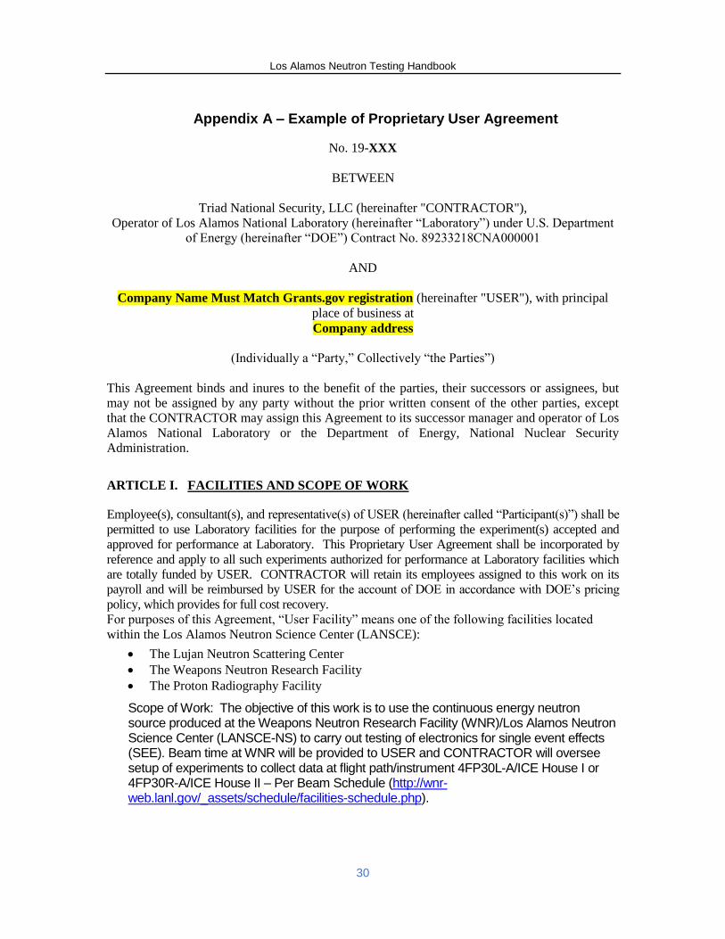
Appendix A – Example of Proprietary User Agreement
No. 19-XXX
BETWEEN
Triad National Security, LLC (hereinafter "CONTRACTOR"),
Operator of Los Alamos National Laboratory (hereinafter “Laboratory”) under U.S. Department
of Energy (hereinafter “DOE”) Contract No. 89233218CNA000001
AND
Company Name Must Match Grants.gov registration (hereinafter "USER"), with principal
place of business at
Company address
(Individually a “Party,” Collectively “the Parties”)
This Agreement binds and inures to the benefit of the parties, their successors or assignees, but
may not be assigned by any party without the prior written consent of the other parties, except
that the CONTRACTOR may assign this Agreement to its successor manager and operator of Los
Alamos National Laboratory or the Department of Energy, National Nuclear Security
Administration.
ARTICLE I. FACILITIES AND SCOPE OF WORK
Employee(s), consultant(s), and representative(s) of USER (hereinafter called “Participant(s)”) shall be
permitted to use Laboratory facilities for the purpose of performing the experiment(s) accepted and
approved for performance at Laboratory. This Proprietary User Agreement shall be incorporated by
reference and apply to all such experiments authorized for performance at Laboratory facilities which
are totally funded by USER. CONTRACTOR will retain its employees assigned to this work on its
payroll and will be reimbursed by USER for the account of DOE in accordance with DOE’s pricing
policy, which provides for full cost recovery.
For purposes of this Agreement, “User Facility” means one of the following facilities located
within the Los Alamos Neutron Science Center (LANSCE):
The Lujan Neutron Scattering Center
The Weapons Neutron Research Facility
The Proton Radiography Facility
Scope of Work: The objective of this work is to use the continuous energy neutron source produced at the Weapons Neutron Research Facility (WNR)/Los Alamos Neutron Science Center (LANSCE-NS) to carry out testing of electronics for single event effects (SEE). Beam time at WNR will be provided to USER and CONTRACTOR will oversee setup of experiments to collect data at flight path/instrument 4FP30L-A/ICE House I or 4FP30R-A/ICE House II – Per Beam Schedule (http://wnr-web.lanl.gov/_assets/schedule/facilities-schedule.php).
Los Alamos Neutron Testing Handbook
31
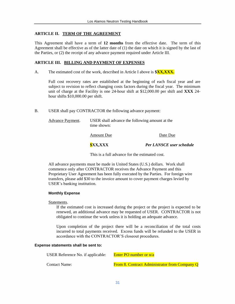
ARTICLE II. TERM OF THE AGREEMENT
This Agreement shall have a term of 12 months from the effective date. The term of this
Agreement shall be effective as of the latter date of (1) the date on which it is signed by the last of
the Parties, or (2) the receipt of any advance payment required under Article III.
ARTICLE III. BILLING AND PAYMENT OF EXPENSES
A. The estimated cost of the work, described in Article I above is $XX,XXX.
Full cost recovery rates are established at the beginning of each fiscal year and are
subject to revision to reflect changing costs factors during the fiscal year. The minimum
unit of charge at the Facility is one 24-hour shift at $12,000.00 per shift and XXX 24-
hour shifts $10,000.00 per shift.
B. USER shall pay CONTRACTOR the following advance payment:
Advance Payment. USER shall advance the following amount at the
time shown:
Amount Due Date Due
$XX,XXX Per LANSCE user schedule
This is a full advance for the estimated cost.
All advance payments must be made in United States (U.S.) dollars. Work shall
commence only after CONTRACTOR receives the Advance Payment and this
Proprietary User Agreement has been fully executed by the Parties. For foreign wire
transfers, please add $30 to the invoice amount to cover payment charges levied by
USER’s banking institution.
Monthly Expense
Statements.
If the estimated cost is increased during the project or the project is expected to be
renewed, an additional advance may be requested of USER. CONTRACTOR is not
obligated to continue the work unless it is holding an adequate advance.
Upon completion of the project there will be a reconciliation of the total costs
incurred to total payments received. Excess funds will be refunded to the USER in
accordance with the CONTRACTOR’S closeout procedures. Expense statements shall be sent to:
USER Reference No. if applicable:
Enter PO number or n/a
Contact Name:
From 8. Contract Administrator from Company Q
Los Alamos Neutron Testing Handbook
32
Street Address:
City, State, Zip Code:
Country:
Telephone with area code:
Email:
Address
Address
Country
Phone
The institutional contact at LANL is:
PUA Team
Los Alamos National Laboratory
P.O. Box 1663, FCI-DO, MS C334
Los Alamos, NM 87545
Phone: 505-665-9090
Email: [email protected]
C. Costs of Experiments will be in accordance with DOE Order O 522.1, “Pricing of
Departmental Materials and Services.”
ARTICLE IV: ADMISSION REQUIREMENTS
USERs and Participants are subject to the administrative and technical supervision and control of
CONTRACTOR; and will comply with all applicable rules of CONTRACTOR and DOE with
regard to admission to and use of the User Facility, including safety, operating and health-physics
procedures, environment protection, access to information, hours of work, and conduct.
Participants shall execute any and all documents required by CONTRACTOR acknowledging
and agreeing to comply with such applicable rules of CONTRACTOR. Participants will not be
considered employees of CONTRACTOR for any purpose.
ARTICLE V. PROPERTY AND MATERIALS
USER may be permitted by the Contractor to furnish equipment, tooling, test apparatus, or
materials necessary to assist in the performance of its experiment(s) at the User Facility. Such
items shall remain the property of USER. Unless the Parties otherwise agree, all such property
furnished by USER or equipment and test apparatus provided by USER will be removed by
USER within sixty (60) days of termination or expiration of this Agreement or will be disposed of
as directed by USER at User’s expense. Any equipment that becomes integrated into the User
Facility shall be the property of the Government. USER acknowledges that any material supplied
by USER may be damaged, consumed or lost. Materials (including residues and/or other
contaminated material) remaining after performance of the work or analysis will be removed in
their then condition by USER at USER's expense. USER will return User Facility and equipment
utilized in their original condition except for normal wear and tear.
CONTRACTOR shall have no responsibility for USER's property at the User Facility other than
loss or damage caused by willful misconduct or gross negligence of CONTRACTOR or its
employees.
Personal property produced or acquired during the course of this Agreement shall be disposed of
as directed by the owner at the owner’s expense.
Los Alamos Neutron Testing Handbook
33
ARTICLE VI: SCHEDULING
USER understands that CONTRACTOR will have sole responsibility and discretion for allocating and scheduling usage of the User Facility and equipment needed for or involved under this Agreement.
ARTICLE VII: INDEMNITY AND LIABILITY
A. Personnel Relationships - USER shall be responsible for the acts or omissions of
Participants.
B. Product Liability - To the extent permitted by U.S. and U.S. State law, if USER utilizes
the work derived from this Agreement in the making, using, or selling of a product,
process or service, then USER hereby agrees to hold harmless and indemnify
CONTRACTOR and the United States Government, their officers, agents and employees
from any and all liability, claims, damages, costs and expenses, including attorney fees,
for injury to or death of persons, or damage to or destruction of property, as a result of or
arising out of such utilization of the work by or on behalf of USER, its assignees or
licensees.
C. General Indemnity - To the extent permitted by U.S. and U.S. State law, USER hereby
agrees to indemnify and hold harmless CONTRACTOR and the United States
Government, their officers, agents and employees from any and all liability, claims,
damages, costs and expenses, including attorney fees, for injury to or death of persons, or
damage to or destruction of property, arising out of the performance of this Agreement or
arising out of the use of the services performed, materials supplied or information given
hereunder by any persons including the USER, and not directly resulting from the fault or
negligence of the Contractor or the United States Government, or persons acting on their
behalf.
D. Patent and Copyright Indemnity—Limited - To the extent permitted by U.S. and U.S.
State law, USER shall fully indemnify the Government and CONTRACTOR and their
officers, agents, and employees for infringement of any United States patent or copyright
arising out of any acts required or directed or performed by USER under the Agreement
to the extent such acts are not normally performed at the facility.
E. The liability and indemnity provisions in paragraphs B, C and D above shall not apply
unless USER shall have been informed as soon as practicable by CONTRACTOR or the
Government of the suit or action alleging such liability or infringement, and such
indemnity shall not apply to a claimed liability or infringement that is settled without the
consent of USER unless required by a court of competent jurisdiction.
F. General Disclaimer -
THE GOVERNMENT AND CONTRACTOR MAKE NO EXPRESS OR IMPLIED
WARRANTY AS TO THE CONDITIONS OF THE USER FACILITY FURNISHED
HEREUNDER. IN ADDITION, THE GOVERNMENT, CONTRACTOR AND USER
MAKE NO EXPRESS OR IMPLIED WARRANTY AS TO THE RESEARCH OR ANY
INTELLECTUAL PROPERTY, GENERATED INFORMATION, OR PRODUCT
MADE OR DEVELOPED UNDER THIS AGREEMENT, OR THE OWNERSHIP,
MERCHANTABILITY, OR FITNESS FOR A PARTICULAR PURPOSE OF THE
Los Alamos Neutron Testing Handbook
34
RESEARCH OR RESULTING PRODUCT; THAT THE GOODS, SERVICES,
MATERIALS, PRODUCTS, PROCESSES, INFORMATION, OR DATA TO BE
FURNISHED HEREUNDER WILL ACCOMPLISH INTENDED RESULTS OR ARE
SAFE FOR ANY PURPOSE INCLUDING THE INTENDED PURPOSE; OR THAT
ANY OF THE ABOVE WILL NOT INTERFERE WITH PRIVATELY OWNED
RIGHTS OF OTHERS. THE GOVERNMENT, CONTRACTOR AND/OR USER
SHALL NOT BE LIABLE FOR SPECIAL, CONSEQUENTIAL, OR INCIDENTAL
DAMAGES ATTRIBUTED TO USE OF SUCH FACILITIES, RESEARCH OR
RESULTING PRODUCT, INTELLECTUAL PROPERTY, GENERATED
INFORMATION, OR PRODUCT MADE OR DELIVERED UNDER THIS
AGREEMENT.
G. Notice and Assistance Regarding Patent and Copyright Infringement
a. USER shall report to the Government, promptly and in reasonable written detail,
each notice or claim of patent or copyright infringement based on the performance
of this Agreement of which USER has knowledge.
b. In the event of any claim or suit against the Government on account of any
alleged patent or copyright infringement arising out of the performance of this
Agreement or out of the use of any supplies furnished or work or services
performed hereunder, USER shall furnish to the Government when requested by
the Government, all evidence and information in possession of USER pertaining
to such suit or claim. Such evidence and information shall be furnished at the
expense of the Government except where USER has agreed to indemnify the
Government.
ARTICLE VIII. PATENT RIGHTS
A. Definitions
1. “Subject Invention” means any invention or discovery of USER conceived or
first actually reduced to practice in the course of or under this Agreement.
2. “Patent Counsel” means the DOE Patent Counsel assisting the Facility Operator.
B. Rights of USER – Election to Retain Rights
With respect to any USER Subject Invention, which includes inventions of any
Participants, reported and elected in accordance with Paragraph C. of this clause, USER
may elect to obtain the entire right, title and interest in any patent application filed in any
country on a Subject Invention and in any resulting patent secured by USER. Where
appropriate, the filing of patent application by USER is subject to DOE security
regulations and requirements.
C. Invention Identification, Disclosures, and Reports
USER shall furnish the Patent Counsel a written report concerning each USER Subject
Invention, which includes inventions of any Participants, within six months after
Los Alamos Neutron Testing Handbook
35
conception or first actual reduction to practice, whichever occurs first. If USER wishes
to elect title to the Subject Invention, a notice of election to the Subject Invention should
be submitted with the report or within one year of such date of reporting of the Subject
Invention.
D. Facilities License
USER agrees to and does hereby grant to the Government an irrevocable, nonexclusive
paid-up license in and to any inventions or discoveries, regardless of when conceived or
actually reduced to practice or acquired by USER, which at any time through completion
of this Agreement are owned or controlled by USER and are incorporated in the User
Facility as a result of this Agreement to such an extent that the User Facility is not
restored to the condition existing prior to the Agreement (1) to practice or to have
practiced by or for the Government at the user Facility, and (2) to transfer such licenses
with the transfer of that User Facility. The acceptance or exercise by the Government of
the aforesaid rights and license shall not prevent the Government at any time from
contesting the enforceability, validity or scope of, or title to, any rights or patents herein
licensed
ARTICLE IX. RIGHTS IN TECHNICAL DATA
A. Definitions
1. "Technical Data" means recorded information, regardless of form or
characteristic, of a scientific or technical nature. Technical data as used herein
does not include financial reports, cost analyses, and other information
incidental to agreement administration.
2. "Proprietary Data" means technical data which embody trade secrets, developed
at private expense, such as design procedures or techniques, chemical
composition of materials, or manufacturing methods, processes or treatments,
including minor modifications thereof, provided that such data:
a. are not generally known or available from other sources without
obligation concerning their confidentiality,
b. have not been made available by the owner to others without obligation
concerning their confidentiality,
c. are not already available to the Government without obligation
concerning their confidentiality, and
d. are marked as “Proprietary Data.”.
3. "Unlimited Rights" means rights to use, duplicate or disclose technical data, in
whole or in part, in any manner and for any purpose whatsoever, and to permit
others to do so.
B. USER agrees to furnish to DOE or CONTRACTOR those data, if any, which are (1)
essential to the performance of work by DOE or CONTRACTOR personnel or (2)
necessary for the health and safety of such personnel in the performance of the work.
Any data furnished to DOE or CONTRACTOR shall be deemed to have been delivered
with unlimited rights unless marked as "Proprietary Data" of USER.
C. USER agrees that it shall have the sole responsibility for identifying and marking all
documents containing Proprietary Data which are furnished by USER or produced under
Los Alamos Neutron Testing Handbook
36
this Agreement. USER further agrees to mark each such document by or before
termination of the Agreement by placing on the cover page thereof a legend identifying
the document as Proprietary Data of USER and identifying each page and portion thereof
to which the marking applies. The Government and CONTRACTOR shall not disclose
properly marked Proprietary Data of USER outside the Government and
CONTRACTOR. The Government and CONTRACTOR reserve the right to challenge
the proprietary nature of any markings on data.
D. USER is solely responsible for the removal of all of its Proprietary Data from the facility
by or before termination of this Agreement. The Government shall have unlimited rights
in any Technical Data (including Proprietary Data) which are not removed from the
facility by or before termination of the Agreement. The Government shall have
unlimited rights in any Technical Data (including Proprietary Data) which are
incorporated into the User Facility under the Agreement to such extent that the User
Facility or equipment is not restored to the condition existing prior to such incorporation.
E. Upon completion or termination of the project, USER agrees to deliver to DOE and
CONTRACTOR a non-proprietary report describing the work performed under the
Agreement.
ARTICLE X. LABORATORY SITE ACCESS, SAFETY AND HEALTH
As a precondition to using CONTRACTOR User Facilities, Participants must complete all
CONTRACTOR Site Access documents and requirements. USER and Participants shall take all
reasonable precautions in activities carried out under this Agreement to protect the safety and
health of others and to protect the environment. Participants must comply with all applicable
safety, health, access to information, security and environmental regulations and the requirements
of the DOE and CONTRACTOR, including the specific requirements of the User Facility
covered by this Agreement. In the event that USER or Participant fails to comply with said
regulations and requirements, CONTRACTOR may, without prejudice to any other legal or
contractual rights, issue and order stopping all or any part of USER’s or Participant’s activities at
the User Facility.
ARTICLE XI. PERSONNEL RELATIONSHIPS
Participants will remain employees or representatives of USER at all times during their
participation in the work under this Agreement and shall not be considered employees of
CONTRACTOR or DOE for any purpose. Participants shall be subject to the administrative and
technical supervision and control of CONTRACTOR during and in connection with the
Participants’ activities under this Agreement.
ARTICLE XII. EXPORT CONTROLS
USER acknowledges that the export of goods or Technical Data may require some form of export
control license from the U.S. Government and that failure to obtain such export control license
may result in criminal liability under the laws of the United States.
ARTICLE XIII. THIRD-PARTY CONTRACTS
Contracts between USER and third parties for work on CONTRACTOR premises including, but
not limited to, construction, installation, maintenance, and repair, will be subject to prior approval
Los Alamos Neutron Testing Handbook
37
by the DOE and CONTRACTOR. The DOE and CONTRACTOR may require the insertion of
specific terms and conditions into such contracts.
ARTICLE XIV. DISPUTES
The parties will attempt to jointly resolve all disputes arising under this agreement. If the parties
are unable to jointly resolve a dispute within a reasonable period of time, either party may contact
the laboratory's Technology Transfer Ombudsman (TTO) to provide assistance. The TTO may
work directly to resolve the dispute or, upon mutual agreement of the parties, contact a third party
neutral mediator to assist the parties in coming to a resolution. The costs of the mediator's
services will be shared equally by the parties. In the event that an agreement is not reached with
the aid of the ombudsman or mediator, the parties may agree to have the dispute addressed by
neutral evaluation. The decision rendered by the neutral evaluator shall be nonbinding on the
parties, and any costs incurred there from shall be divided equally between the parties. Upon
mutual agreement, the parties may request a final decision by the DOE Contracting Officer.
Absent resolution, either party may seek relief in a court of competent jurisdiction.
ARTICLE XV. CONFLICT OF TERMS
In the event of any conflict between the terms of this document and any other document issued by
either Party, the terms of this document shall prevail.
ARTICLE XVI. TERMINATION
Either Party may terminate this Agreement for any reason at any time by giving not less than
thirty (30) days prior written notice to the other Party, provided that CONTRACTOR shall
recover payment for the costs incurred by CONTRACTOR on behalf of USER prior to
termination and for termination costs.
In witness whereof, the Parties hereto have executed this Agreement:
FOR THE CONTRACTOR:
BY: ____________________________________________
Antonio Redondo, Division Leader for the Richard P. Feynman Center for Innovation
or for foreign (address, yes to 2 or 3 on Company Q or if parent address is foreign)
John Sarrao Deputy Laboratory Director for Science, Technology, & Engineering
DATE: _________________________________________
FOR THE USER:
BY: ____________________________________________
Name, Title from 9. Signature Authority on Company Q
Company Name
DATE: _________________________________________
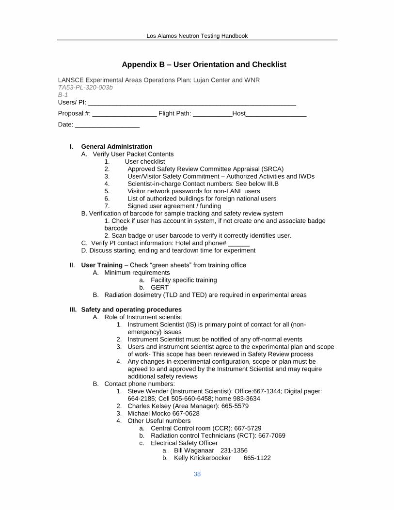
Los Alamos Neutron Testing Handbook
38
Appendix B – User Orientation and Checklist LANSCE Experimental Areas Operations Plan: Lujan Center and WNR TA53-PL-320-003b B-1 Users/ PI: __________________________________________________________
Proposal #: __________________ Flight Path: ___________Host_________________
Date: __________________
I. General Administration A. Verify User Packet Contents
1. User checklist 2. Approved Safety Review Committee Appraisal (SRCA) 3. User/Visitor Safety Commitment – Authorized Activities and IWDs 4. Scientist-in-charge Contact numbers: See below III.B 5. Visitor network passwords for non-LANL users 6. List of authorized buildings for foreign national users 7. Signed user agreement / funding
B. Verification of barcode for sample tracking and safety review system 1. Check if user has account in system, if not create one and associate badge barcode 2. Scan badge or user barcode to verify it correctly identifies user.
C. Verify PI contact information: Hotel and phone# ______ D. Discuss starting, ending and teardown time for experiment
II. User Training – Check “green sheets” from training office A. Minimum requirements
a. Facility specific training b. GERT
B. Radiation dosimetry (TLD and TED) are required in experimental areas
III. Safety and operating procedures A. Role of Instrument scientist
1. Instrument Scientist (IS) is primary point of contact for all (non-emergency) issues
2. Instrument Scientist must be notified of any off-normal events 3. Users and instrument scientist agree to the experimental plan and scope
of work- This scope has been reviewed in Safety Review process 4. Any changes in experimental configuration, scope or plan must be
agreed to and approved by the Instrument Scientist and may require additional safety reviews
B. Contact phone numbers: 1. Steve Wender (Instrument Scientist): Office:667-1344; Digital pager:
664-2185; Cell 505-660-6458; home 983-3634 2. Charles Kelsey (Area Manager): 665-5579 3. Michael Mocko 667-0628 4. Other Useful numbers
a. Central Control room (CCR): 667-5729 b. Radiation control Technicians (RCT): 667-7069 c. Electrical Safety Officer
a. Bill Waganaar 231-1356 b. Kelly Knickerbocker 665-1122
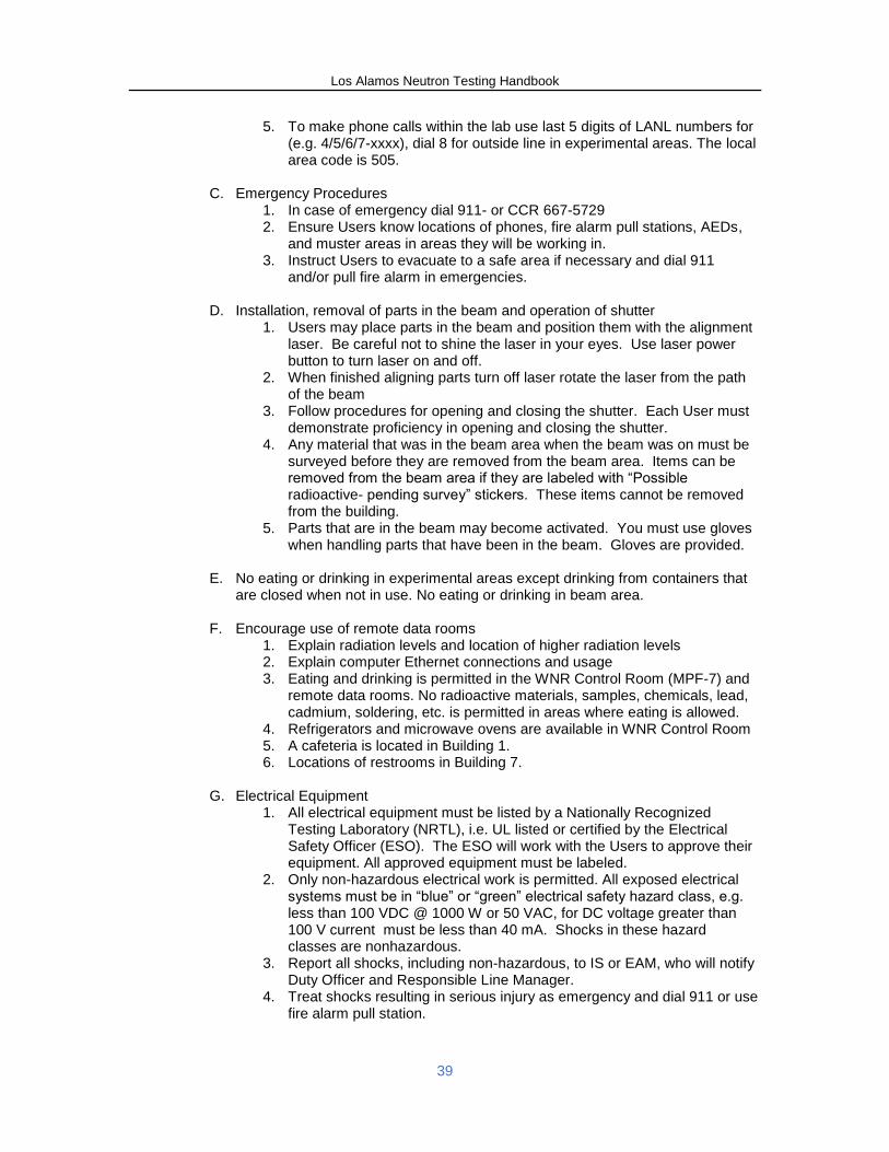
Los Alamos Neutron Testing Handbook
39
5. To make phone calls within the lab use last 5 digits of LANL numbers for (e.g. 4/5/6/7-xxxx), dial 8 for outside line in experimental areas. The local area code is 505.
C. Emergency Procedures 1. In case of emergency dial 911- or CCR 667-5729 2. Ensure Users know locations of phones, fire alarm pull stations, AEDs,
and muster areas in areas they will be working in. 3. Instruct Users to evacuate to a safe area if necessary and dial 911
and/or pull fire alarm in emergencies.
D. Installation, removal of parts in the beam and operation of shutter 1. Users may place parts in the beam and position them with the alignment
laser. Be careful not to shine the laser in your eyes. Use laser power button to turn laser on and off.
2. When finished aligning parts turn off laser rotate the laser from the path of the beam
3. Follow procedures for opening and closing the shutter. Each User must demonstrate proficiency in opening and closing the shutter.
4. Any material that was in the beam area when the beam was on must be surveyed before they are removed from the beam area. Items can be removed from the beam area if they are labeled with “Possible radioactive- pending survey” stickers. These items cannot be removed from the building.
5. Parts that are in the beam may become activated. You must use gloves when handling parts that have been in the beam. Gloves are provided.
E. No eating or drinking in experimental areas except drinking from containers that are closed when not in use. No eating or drinking in beam area.
F. Encourage use of remote data rooms 1. Explain radiation levels and location of higher radiation levels 2. Explain computer Ethernet connections and usage 3. Eating and drinking is permitted in the WNR Control Room (MPF-7) and
remote data rooms. No radioactive materials, samples, chemicals, lead, cadmium, soldering, etc. is permitted in areas where eating is allowed.
4. Refrigerators and microwave ovens are available in WNR Control Room 5. A cafeteria is located in Building 1. 6. Locations of restrooms in Building 7.
G. Electrical Equipment
1. All electrical equipment must be listed by a Nationally Recognized Testing Laboratory (NRTL), i.e. UL listed or certified by the Electrical Safety Officer (ESO). The ESO will work with the Users to approve their equipment. All approved equipment must be labeled.
2. Only non-hazardous electrical work is permitted. All exposed electrical systems must be in “blue” or “green” electrical safety hazard class, e.g. less than 100 VDC @ 1000 W or 50 VAC, for DC voltage greater than 100 V current must be less than 40 mA. Shocks in these hazard classes are nonhazardous.
3. Report all shocks, including non-hazardous, to IS or EAM, who will notify Duty Officer and Responsible Line Manager.
4. Treat shocks resulting in serious injury as emergency and dial 911 or use fire alarm pull station.
Los Alamos Neutron Testing Handbook
40
H. Chemicals and other hazardous materials 1. Ask users if they have brought chemicals or other hazardous materials. 2. Ask Users if they brought any radioactive material including sources or
equipment that may have been in a beam before coming to LANSCE
I. Environmental hazards 1. Potential for hot/cold outdoor temperatures, altitude sickness, intense
sun, dehydration, wildlife, and icy conditions. 2. Locations of ice melt containers and encourage users to report any
safety concerns to IS or EAM.
IV. Site entry gate operation A. During the day (6:30-18:30): All vehicle occupants must show badge to guards
when entering. You do not have to stop when leaving. Drive slowly. B. After hours and weekends: Everyone in car must swipe badge to enter. C. Drive slowly towards exit gate when closed. It should open automatically. Push
button to exit if gate does not automatically open. D. If there are problems with the badger reader, call CCR for assistance
V. Door locks ICE House buildings are opened using digital locks. The remote data rooms
have the same key codes as the ICE Houses
VI. Photographic policy Pictures may be taken only with LANL cameras.
A. IS will give you a LANL camera to use. B. Pictures should be related to work / what you will show in presentation C. Identification badges may not be shown in photographs D. The pictures will be downloaded and sent to you after they are reviewed.
VII. Computer usage A. You can use your personal computers on the User Network (internet). You can
use your personal computers to connect to your control computers using the experiment network which connects the remote data rooms to the experimental areas.
B. You may use LANL computers to connect to your computers in the experimental areas from the remote data rooms.
C. Provide Users Visitor Network passwords. D. Restrictions on computer usage- adult sites, gambling, business.
VIII. Status board and status pages
A. Status screens are available in the WNR control room and the remote data rooms
B. You can log into the status screens at the following URLs: Lansce.lanl.gov click Beam Status at top of page
X. End of experiment procedures A. Anything that has been in the beam area when the beam was on must be
surveyed before it can be removed from the area. B. At the end of the experiment, all material that was in the beam area when beam
was on will be surveyed. If the material is radioactive, it will be stored in a labeled plastic bin in the sample transportainer until it is re-surveyed. If the material is shows no detectable activity (NDA), it can be returned to the Users.
Los Alamos Neutron Testing Handbook
41
C. Each storage bin should be labeled with the User contact name, phone number and e-mail, the company/ institution name and address. The bin should be labeled as containing radioactive material. A label from the sample logging system is generated and attached to the bin for each bin used. The activated material will be surveyed periodically and when found to be NDA, it will be returned to the User.
D. When leaving the site for the last time, return the LANL visitor badge and dosimeters to badge drop-box on north side guard shack outside main gate.
E. If LANL will be shipping equipment back to Users after they leave, have the Users complete a shipping a label for each plastic bin. The label should include the User contact name, phone number and e-mail, the company/ institution name and address,
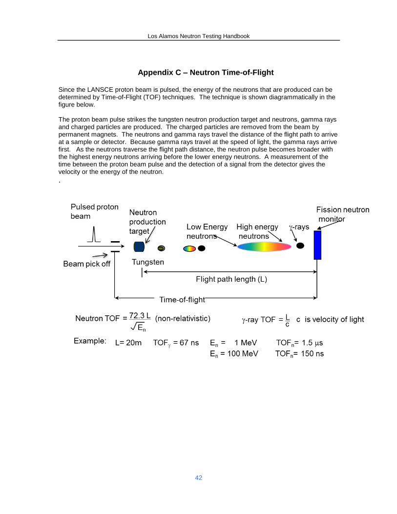
Los Alamos Neutron Testing Handbook
42
Appendix C – Neutron Time-of-Flight
Since the LANSCE proton beam is pulsed, the energy of the neutrons that are produced can be determined by Time-of-Flight (TOF) techniques. The technique is shown diagrammatically in the figure below. The proton beam pulse strikes the tungsten neutron production target and neutrons, gamma rays and charged particles are produced. The charged particles are removed from the beam by permanent magnets. The neutrons and gamma rays travel the distance of the flight path to arrive at a sample or detector. Because gamma rays travel at the speed of light, the gamma rays arrive first. As the neutrons traverse the flight path distance, the neutron pulse becomes broader with the highest energy neutrons arriving before the lower energy neutrons. A measurement of the time between the proton beam pulse and the detection of a signal from the detector gives the velocity or the energy of the neutron.
.