Embed Size (px)
Citation preview
1
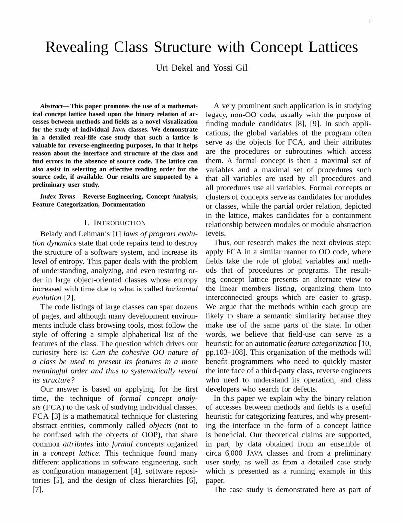
Revealing Class Structure with Concept LatticesUri Dekel and Yossi Gil
Abstract— This paper promotes the use of a mathemat-ical concept lattice based upon the binary relation of ac-cesses between methods and fields as a novel visualizationfor the study of individual JAVA classes. We demonstratein a detailed real-life case study that such a lattice isvaluable for reverse-engineering purposes, in that it helpsreason about the interface and structure of the class andfind errors in the absence of source code. The lattice canalso assist in selecting an effective reading order for thesource code, if available. Our results are supported by apreliminary user study.
Index Terms— Reverse-Engineering, Concept Analysis,Feature Categorization, Documentation
I. I NTRODUCTION
Belady and Lehman’s [1]laws of program evolu-tion dynamicsstate that code repairs tend to destroythe structure of a software system, and increase itslevel of entropy. This paper deals with the problemof understanding, analyzing, and even restoring or-der in large object-oriented classes whose entropyincreased with time due to what is calledhorizontalevolution[2].
The code listings of large classes can span dozensof pages, and although many development environ-ments include class browsing tools, most follow thestyle of offering a simple alphabetical list of thefeatures of the class. The question which drives ourcuriosity here is:Can the cohesive OO nature ofa class be used to present its features in a moremeaningful order and thus to systematically revealits structure?
Our answer is based on applying, for the firsttime, the technique offormal concept analy-sis (FCA) to the task of studying individual classes.FCA [3] is a mathematical technique for clusteringabstract entities, commonly calledobjects (not tobe confused with the objects of OOP), that sharecommonattributes into formal conceptsorganizedin a concept lattice. This technique found manydifferent applications in software engineering, suchas configuration management [4], software reposi-tories [5], and the design of class hierarchies [6],[7].
A very prominent such application is in studyinglegacy, non-OO code, usually with the purpose offinding module candidates [8], [9]. In such appli-cations, the global variables of the program oftenserve as the objects for FCA, and their attributesare the procedures or subroutines which accessthem. A formal concept is then a maximal set ofvariables and a maximal set of procedures suchthat all variables are used by all procedures andall procedures use all variables. Formal concepts orclusters of concepts serve as candidates for modulesor classes, while the partial order relation, depictedin the lattice, makes candidates for a containmentrelationship between modules or module abstractionlevels.
Thus, our research makes the next obvious step:apply FCA in a similar manner to OO code, wherefields take the role of global variables and meth-ods that of procedures or programs. The result-ing concept lattice presents an alternate view tothe linear members listing, organizing them intointerconnected groups which are easier to grasp.We argue that the methods within each group arelikely to share a semantic similarity because theymake use of the same parts of the state. In otherwords, we believe that field-use can serve as aheuristic for an automaticfeature categorization[10,pp.103–108]. This organization of the methods willbenefit programmers who need to quickly masterthe interface of a third-party class, reverse engineerswho need to understand its operation, and classdevelopers who search for defects.
In this paper we explain why the binary relationof accesses between methods and fields is a usefulheuristic for categorizing features, and why present-ing the interface in the form of a concept latticeis beneficial. Our theoretical claims are supported,in part, by data obtained from an ensemble ofcirca 6,000JAVA classes and from a preliminaryuser study, as well as from a detailed case studywhich is presented as a running example in thispaper.
The case study is demonstrated here as part of
2
a structured three-stage methodology for studyingthe interface, implementation, and (when available)code of an unfamiliar large class. An evidence tothe efficacy of this methodology is that with nobackground and with minimal effort, we revealedproblems which were confirmed as new errors bythe developers and were fixed in subsequent ver-sions. While automatic tools may reveal some ofthe more localized errors, our approach assists indiscovering delocalized problems which are moredifficult to find and require an understanding of theclass and its interface as a whole.
In addition to the methodology, we also describethe embedded call graph, an amalgam of conceptlattices and call graphs, which has the potential ofcombining the two visual methods to obtain newinsights about the class.
Outline Section II is a concise overviewof FCA, demonstrating its application for reverse-engineering a smallJAVA class. We discuss therationale behind our approach in Section III. Thefirst stage of our methodology involves studyingthe class interface and is described in Section IV.The embedded call graph is presented in Section V.Section VI is dedicated to the second stage, inwhich we zoom-in into the implementation details,all without dealing with the source code. Whensources are available, the third stage in Section VII,shows how a sensible reading order can be selectedfor the purpose of carrying out an effective codeinspection. Finally, Section VIII concludes and out-lines directions for future research. The results of apreliminary user study are described in Appendix I.
II. CONCEPTANALYSIS
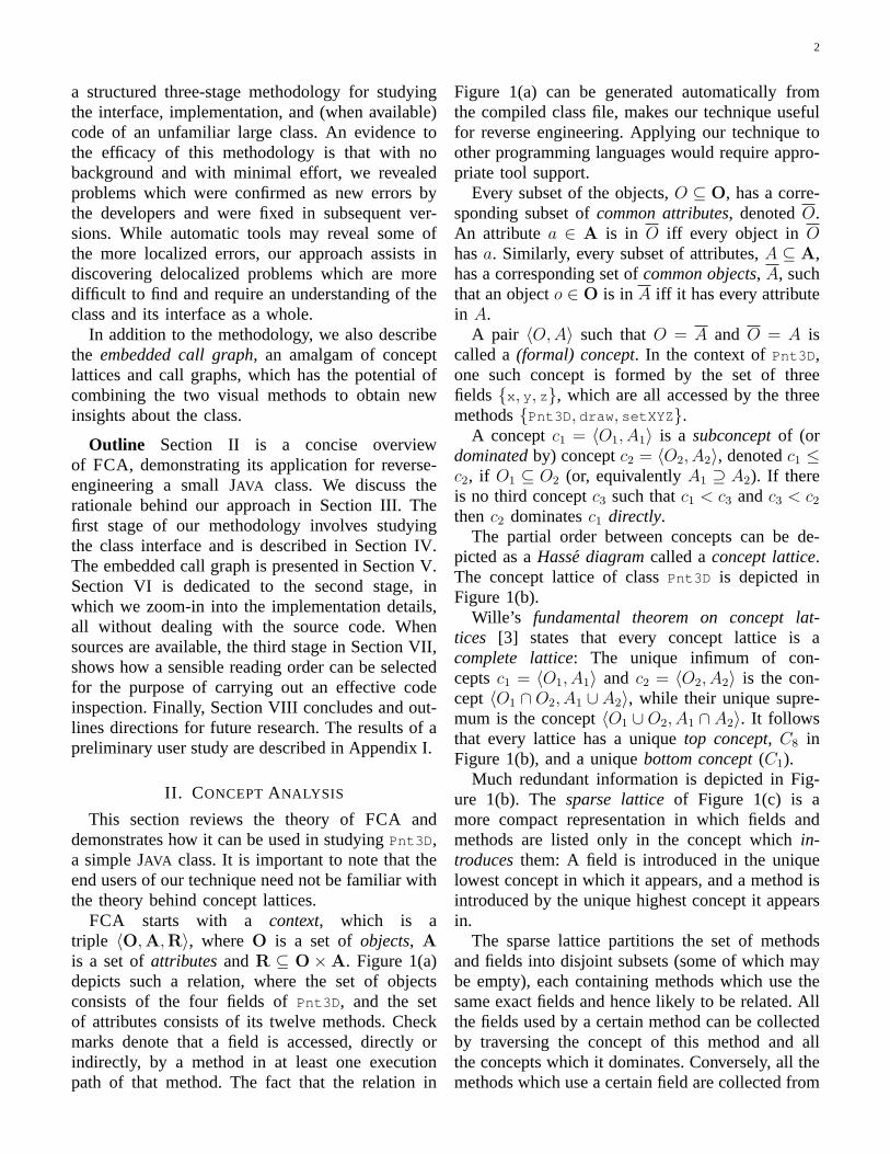
This section reviews the theory ofFCA anddemonstrates how it can be used in studyingPnt3D ,a simpleJAVA class. It is important to note that theend users of our technique need not be familiar withthe theory behind concept lattices.
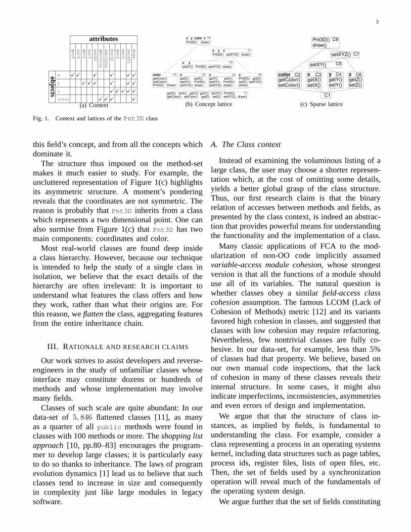
FCA starts with a context, which is atriple 〈O,A,R〉, whereO is a set ofobjects, Ais a set ofattributesandR ⊆ O×A. Figure 1(a)depicts such a relation, where the set of objectsconsists of the four fields ofPnt3D , and the setof attributes consists of its twelve methods. Checkmarks denote that a field is accessed, directly orindirectly, by a method in at least one executionpath of that method. The fact that the relation in
Figure 1(a) can be generated automatically fromthe compiled class file, makes our technique usefulfor reverse engineering. Applying our technique toother programming languages would require appro-priate tool support.
Every subset of the objects,O ⊆ O, has a corre-sponding subset ofcommon attributes, denotedO.An attributea ∈ A is in O iff every object inOhasa. Similarly, every subset of attributes,A ⊆ A,has a corresponding set ofcommon objects, A, suchthat an objecto ∈ O is in A iff it has every attributein A.
A pair 〈O, A〉 such thatO = A and O = A iscalled a(formal) concept. In the context ofPnt3D ,one such concept is formed by the set of threefields {x , y , z}, which are all accessed by the threemethods{Pnt3D , draw , setXYZ }.
A conceptc1 = 〈O1, A1〉 is a subconceptof (ordominatedby) conceptc2 = 〈O2, A2〉, denotedc1 ≤c2, if O1 ⊆ O2 (or, equivalentlyA1 ⊇ A2). If thereis no third conceptc3 such thatc1 < c3 andc3 < c2
thenc2 dominatesc1 directly.The partial order between concepts can be de-
picted as aHasse diagramcalled aconcept lattice.The concept lattice of classPnt3D is depicted inFigure 1(b).
Wille’s fundamental theorem on concept lat-tices [3] states that every concept lattice is acomplete lattice: The unique infimum of con-ceptsc1 = 〈O1, A1〉 and c2 = 〈O2, A2〉 is the con-cept 〈O1 ∩O2, A1 ∪ A2〉, while their unique supre-mum is the concept〈O1 ∪O2, A1 ∩ A2〉. It followsthat every lattice has a uniquetop concept, C8 inFigure 1(b), and a uniquebottom concept(C1).
Much redundant information is depicted in Fig-ure 1(b). Thesparse latticeof Figure 1(c) is amore compact representation in which fields andmethods are listed only in the concept whichin-troducesthem: A field is introduced in the uniquelowest concept in which it appears, and a method isintroduced by the unique highest concept it appearsin.
The sparse lattice partitions the set of methodsand fields into disjoint subsets (some of which maybe empty), each containing methods which use thesame exact fields and hence likely to be related. Allthe fields used by a certain method can be collectedby traversing the concept of this method and allthe concepts which it dominates. Conversely, all themethods which use a certain field are collected from
3
attributes
ge
tXse
tX
ge
tYse
tY
setX
Y
ge
tCo
lor
setC
olo
r
Pn
t3D
ge
tZse
tZ
setX
YZ
dra
w
objects
x X X X X X Xy X X X X X Xz X X X X Xcolor X X X X
(a) Context
x
getX() setX() setXY() Pnt3D() setXYZ() draw()
C3
getX() setX() getY() getY() setXY() Pnt3D() getColor() setColor() getZ() setZ() setXYZ() draw()
C1
x y
setXY() Pnt3D() setXYZ() draw()
C5
Pnt3D() setXYZ() draw()
x y z C7
x y color z
Pnt3D() draw()
C8
color getColor() setColor() Pnt3D() Draw()
C2 y
getY() setY() setXY() Pnt3D() setXYZ() draw()
C4 z
Pnt3D() getZ() setZ() setXYZ() draw()
C6
(b) Concept lattice
color getColor() setColor()
setXY() C5
C1
C2
setXYZ() C7
Pnt3D() draw()
C8
z getZ() setZ()
C6 x getX() setX()
C3 y getY() setY()
C4
(c) Sparse lattice
Fig. 1. Context and lattices of thePnt3D class
this field’s concept, and from all the concepts whichdominate it.
The structure thus imposed on the method-setmakes it much easier to study. For example, theuncluttered representation of Figure 1(c) highlightsits asymmetric structure. A moment’s ponderingreveals that the coordinates are not symmetric. Thereason is probably thatPnt3D inherits from a classwhich represents a two dimensional point. One canalso surmise from Figure 1(c) thatPnt3D has twomain components: coordinates and color.
Most real-world classes are found deep insidea class hierarchy. However, because our techniqueis intended to help the study of a single class inisolation, we believe that the exact details of thehierarchy are often irrelevant: It is important tounderstand what features the class offers and howthey work, rather than what their origins are. Forthis reason, weflattenthe class, aggregating featuresfrom the entire inheritance chain.
III. R ATIONALE AND RESEARCH CLAIMS
Our work strives to assist developers and reverse-engineers in the study of unfamiliar classes whoseinterface may constitute dozens or hundreds ofmethods and whose implementation may involvemany fields.
Classes of such scale are quite abundant: In ourdata-set of5, 846 flattened classes [11], as manyas a quarter of allpublic methods were found inclasses with 100 methods or more. Theshopping listapproach [10, pp.80–83] encourages the program-mer to develop large classes; it is particularly easyto do so thanks to inheritance. The laws of programevolution dynamics [1] lead us to believe that suchclasses tend to increase in size and consequentlyin complexity just like large modules in legacysoftware.
A. The Class context
Instead of examining the voluminous listing of alarge class, the user may choose a shorter represen-tation which, at the cost of omitting some details,yields a better global grasp of the class structure.Thus, our first research claim is that the binaryrelation of accesses between methods and fields, aspresented by the class context, is indeed an abstrac-tion that provides powerful means for understandingthe functionality and the implementation of a class.
Many classic applications of FCA to the mod-ularization of non-OO code implicitly assumedvariable-access module cohesion, whose strongestversion is that all the functions of a module shoulduse all of its variables. The natural question iswhether classes obey a similarfield-access classcohesionassumption. The famous LCOM (Lack ofCohesion of Methods) metric [12] and its variantsfavored high cohesion in classes, and suggested thatclasses with low cohesion may require refactoring.Nevertheless, few nontrivial classes are fully co-hesive. In our data-set, for example, less than 5%of classes had that property. We believe, based onour own manual code inspections, that the lackof cohesion in many of these classes reveals theirinternal structure. In some cases, it might alsoindicate imperfections, inconsistencies, asymmetriesand even errors of design and implementation.
We argue that that the structure of class in-stances, as implied by fields, is fundamental tounderstanding the class. For example, consider aclass representing a process in an operating systemskernel, including data structures such as page tables,process ids, register files, lists of open files, etc.Then, the set of fields used by a synchronizationoperation will reveal much of the fundamentals ofthe operating system design.
We argue further that the set of fields constituting
4
the structure of a class is less volatile than theset of services it provides. Consider the famousexample of the alternative implementations of acomplex number class using the cartesian or thepolar representation. Switching between these alter-natives is tantamount to rewriting the entire class,and is therefore less likely to happen than changingthe services to the class. Similarly, almost everymethod in a class representing a rectangle wouldhave to be rewritten when switching from a two-corners representation to a location-and-dimensionsrepresentation. We also believe that for a fixedrepresentation, it is often the case that all possibleimplementations of the same service will use thesame set of fields.
Our limited experimental validation, presented inAppendix I, supports our first claim, and shows thata context table is indeed a useful tool in its ownright. However, the class context can be representedin a variety of ways, including tables and conceptlattices. Our second claim, supported by the sameexperiment, is that thesparse latticeartifact ofFCAenables an even more effective examination of thecontext.
B. Use of a sparse concept lattice
It is important to remember that although thesparse lattice and the tabular context represent thesame data, the lattice often provides a more compactrepresentation. Whereas a table can have manyempty cells and identical rows or columns, eachfield or method in the sparse lattice is listed exactlyonce. Similarities or equivalencies between rowsand columns are captured by the grouping of themethods and fields into concepts. The question iswhether this compaction is outweighed by a largenumber of empty concepts.
Let F andM be the sets of fields and methods ofa flattened class, respectively. The maximal numberof concepts for its lattice is the size of the smallerpower set of the two:2min(|F|,|M|). In theory, a latticecan approach these exponential bounds, for examplewith a context where every method accesses all thefields save one, and every field is not accessed byat least one method. On the other hand, we sawthePnt3D class, which had only8 concepts despite atheoretical bound of16. This class is not completelychaotic, and only certain combinations of fields areused together.
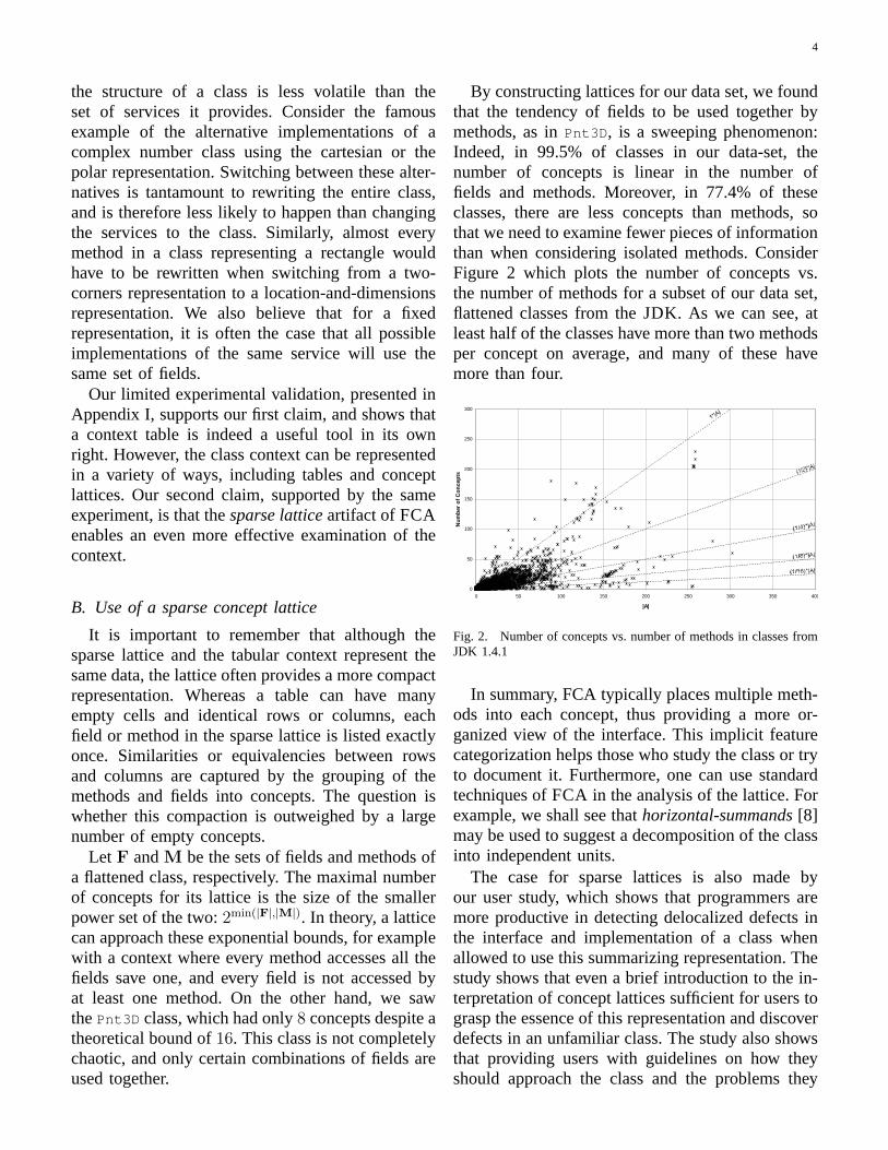
By constructing lattices for our data set, we foundthat the tendency of fields to be used together bymethods, as inPnt3D , is a sweeping phenomenon:Indeed, in 99.5% of classes in our data-set, thenumber of concepts is linear in the number offields and methods. Moreover, in 77.4% of theseclasses, there are less concepts than methods, sothat we need to examine fewer pieces of informationthan when considering isolated methods. ConsiderFigure 2 which plots the number of concepts vs.the number of methods for a subset of our data set,flattened classes from theJDK. As we can see, atleast half of the classes have more than two methodsper concept on average, and many of these havemore than four.
0
50
100
150
200
250
300
0 50 100 150 200 250 300 350 400
|A|
Nu
mb
er o
f C
on
cep
ts
Fig. 2. Number of concepts vs. number of methods in classes fromJDK 1.4.1
In summary, FCA typically places multiple meth-ods into each concept, thus providing a more or-ganized view of the interface. This implicit featurecategorization helps those who study the class or tryto document it. Furthermore, one can use standardtechniques ofFCA in the analysis of the lattice. Forexample, we shall see thathorizontal-summands[8]may be used to suggest a decomposition of the classinto independent units.
The case for sparse lattices is also made byour user study, which shows that programmers aremore productive in detecting delocalized defects inthe interface and implementation of a class whenallowed to use this summarizing representation. Thestudy shows that even a brief introduction to the in-terpretation of concept lattices sufficient for users tograsp the essence of this representation and discoverdefects in an unfamiliar class. The study also showsthat providing users with guidelines on how theyshould approach the class and the problems they
5
should look for often increased their performance.
C. A Methodology for studying classes
Our third claim is that the class structure ismore readily revealed by the lattice when usersfollow a structured inspection methodology. Whileit is a colossal empirical research effort to find theoptimal set of structural aids and then their optimalorder of application, the results of our experimentssuggest that even the guidelines which we providedto subjects may be beneficial. Thus, we presentin this paper one possible (though not necessarilyoptimal) set of guidelines, in the form of a three-stage methodology which utilizes variousFCA-based tools, views and diagrams. These tools areused in our methodology both for abstracting theclass information and for focusing on interestingdetails.
Our methodology is intended, in part, to improvethe unstructured ad-hoc study of classes whichdevelopers perform in the course of themicro de-velopment process[13]. In particular, it does notincur the overhead of a rigorous process, and canbe invoked on a per-need basis. The tools are easyto implement, learn and use, and can be smoothlyintegrated into development environments.
Our running example here isMolecule , a largeclass (77public members, over 1,500 LOC) drawnfrom the Chemistry Development Kit(CDK) [14],[15]1, an open-source library ofJAVA classesfor chemoinformatics and computational chemistrywhich serve as foundation for various applicationsin the field. Prior to the case study selection we werenot familiar with the library or affiliated with itsauthors in any way; nor did we have any particularknowledge of the application domain.
ClassMolecule represents an entity that shouldbe familiar to a wide scientific audience. A chemicalmolecule is essentially a group ofatoms that areconnected bybonds, and can be though of as agraph. Despite the simplicity of this notion, thisclass sports a large interface consisting of77 public
members. The class extendsAtomContainer , whichin turn extendsChemObject . Prior to the analysis theclass wasflattened, as little distinction was madebetween members based on their origins.
Each of the following sections describes astage of our methodology, and demonstrates it on
1We analyzed build 20020518, released in May 2002.
the Molecule class. Another detailed worked-outexample, drawn from a graph-theory domain, canbe found elsewhere [11].
IV. STAGE I: I NTERFACEANALYSIS
In the course of presenting our methodology, weare going to show how different errors can be sys-tematically discovered, and how an understanding ofthe class can be gained in the process. While someof these errors are localized and can be detectedwith other tools and techniques, many are delocal-ized and tend to evade inspectors using traditionalmethods. Note that we do not see error-detectionas the primary goal of our methodology (automatictools may discover many of these problems), butuse it to demonstrate how our approach assists inreasoning about the class.
The first stage of our methodology is to study theclass interface, where the concept latticepartitionsthe public methods into concepts and organizesthem in layers of abstraction. Even though thisstage is primarily concerned with the interface, theprocess is not pure, and we are sometimes forced topeek into the implementation, since, as shown by therunning example, details of the implementation cansneak into the interface. Conversely, an incompleteinterface definition must be elaborated by examiningthe implementation.
There are 7 steps or activities in this stage, whichare not necessarily carried out in sequence; the firstones construct the lattice and zoom-out to obtaina general understanding, and the later ones zoom-in to investigate specific details. We now turn todescribing them briefly; a more detailed discussioncan be found elsewhere [11].Step 1:Become familiar with the abstracted entityand the environment of the class. Even though theconcepts and their lattice are created automatically,their interpretation can only be done by a humanmental effort, to which the main clues are the namesand signatures of methods. In order to make senseof these identifiers, it is essential to become familiarwith the vocabularyand with thehuman contextatwhich the class operates.Step 2: Context selection. The lattice constructionbegins with a selection of an appropriate classcontext. For interface analysis, we start with what iscalled theflat-short formin the EIFFEL jargon [16,p.106]. The selected context consists ofpublic
6
methods only, regardless of theirstatic status;methods defined in ancestors are included, unlessthey were overridden.2 All the fields of the classare included in the context, regardless of theirvisibility and static status. The incidence relationincludes read- or write-access. Note that we do notdistinguish between direct and indirect access to afield. Also, as customary in the relevant literature,no alias-analysis is attempted.
Applying thus FCA to Molecule convenientlyorganizes its 75 methods and twopublic fieldsin 26 concepts.Step 3: Layers-based lattice layout. We expectmore sophisticated methods to use more fields,and hence to be located higher in the lattice. Inexamining many class lattices we also found thatconcepts at the same “layer” tend to have similarproperties. For example, each ofC2, C3, C4, andC6
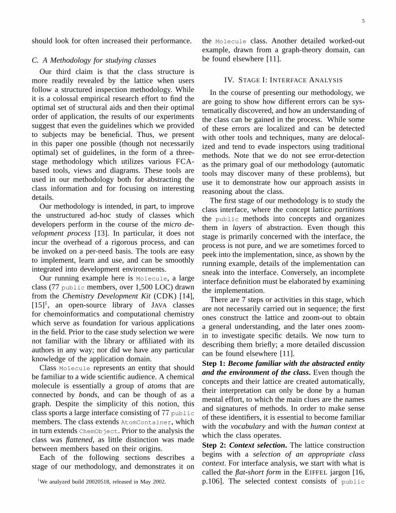
in Figure 1(c) dominates the bottom concept di-rectly. They are also similar in that each introducesa single field with an accessor and mutator for it.Figure 3 shows a partitioning of an example latticeinto layers.
Layer 1 (Bottom)
Layer 2
Layer 3
Layer 4
Layer 5
Top Layer
Top String
Bottom String
Bottom Concept
Top Concept
1
2
3
22
23
24
20
21
17
16
15
18 19
14 4
5 6
7 8
10 9
11 12
13
Fig. 3. Layers and components in an example lattice
Formally, the bottom stringstretches from thebottom concept to the lowest concept that hasmultiple parents; thetop string is defined similarly.Concepts which dominate only the bottom-stringconstitute thebottom(or first) layer, and those onlydominated by the top string (and not in the bottomlayer) constitute thetop layer. A concept belongs totheith internal layer if if it: (i) does not belong to thetop layer,(ii) dominates only concepts in layeri−1and below, and(iii) dominates at least one conceptin layer i− 1.
2Methods declared injava.lang.Object are not includedunless overridden because they are common to allJAVA classes.
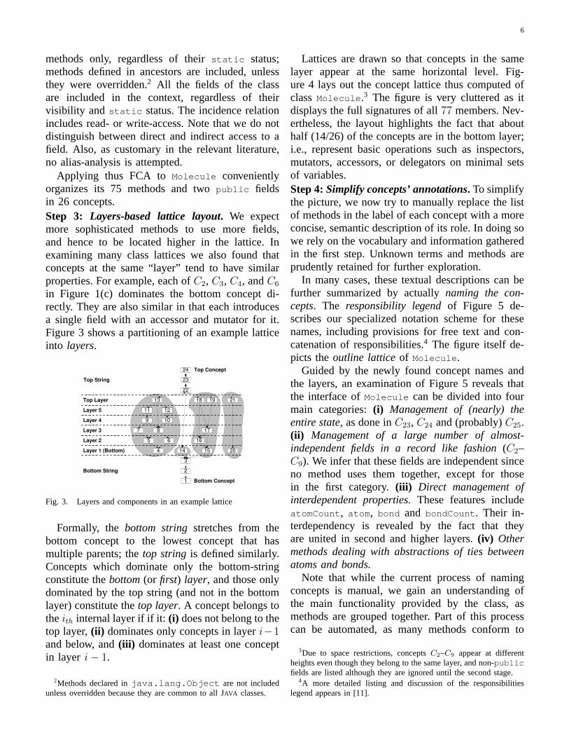
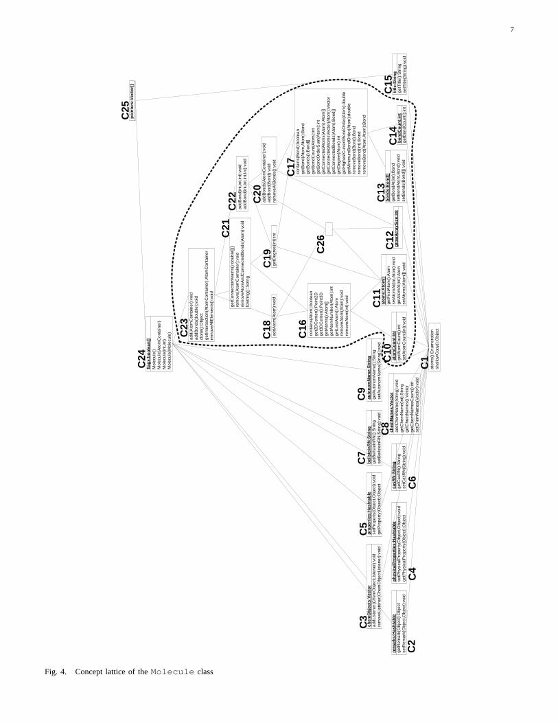
Lattices are drawn so that concepts in the samelayer appear at the same horizontal level. Fig-ure 4 lays out the concept lattice thus computed ofclassMolecule .3 The figure is very cluttered as itdisplays the full signatures of all77 members. Nev-ertheless, the layout highlights the fact that abouthalf (14/26) of the concepts are in the bottom layer;i.e., represent basic operations such as inspectors,mutators, accessors, or delegators on minimal setsof variables.Step 4:Simplify concepts’ annotations. To simplifythe picture, we now try to manually replace the listof methods in the label of each concept with a moreconcise, semantic description of its role. In doing sowe rely on the vocabulary and information gatheredin the first step. Unknown terms and methods areprudently retained for further exploration.
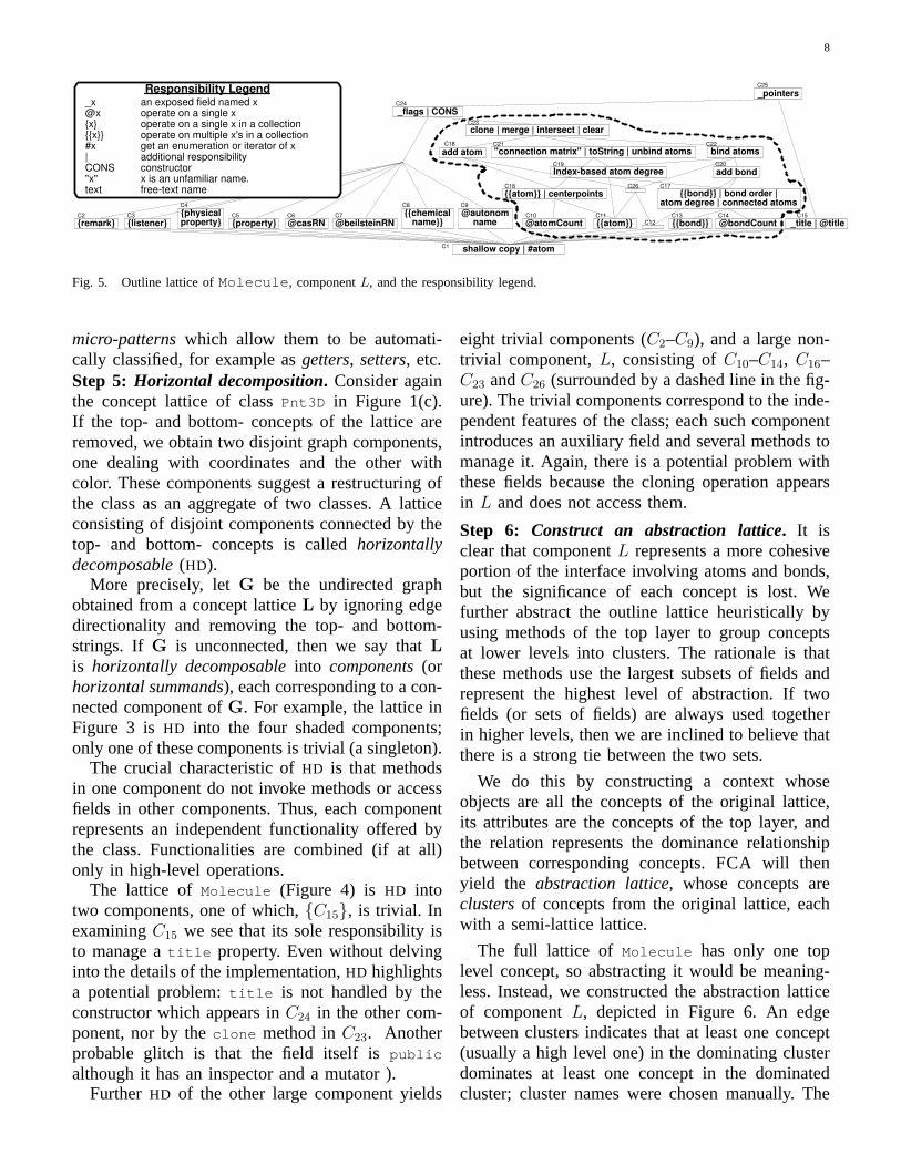
In many cases, these textual descriptions can befurther summarized by actuallynaming the con-cepts. The responsibility legendof Figure 5 de-scribes our specialized notation scheme for thesenames, including provisions for free text and con-catenation of responsibilities.4 The figure itself de-picts theoutline latticeof Molecule .
Guided by the newly found concept names andthe layers, an examination of Figure 5 reveals thatthe interface ofMolecule can be divided into fourmain categories:(i) Management of (nearly) theentire state, as done inC23, C24 and (probably)C25.(ii) Management of a large number of almost-independent fields in a record like fashion(C2–C9). We infer that these fields are independent sinceno method uses them together, except for thosein the first category.(iii) Direct management ofinterdependent properties.These features includeatomCount , atom , bond and bondCount . Their in-terdependency is revealed by the fact that theyare united in second and higher layers.(iv) Othermethods dealing with abstractions of ties betweenatoms and bonds.
Note that while the current process of namingconcepts is manual, we gain an understanding ofthe main functionality provided by the class, asmethods are grouped together. Part of this processcan be automated, as many methods conform to
3Due to space restrictions, conceptsC2–C9 appear at differentheights even though they belong to the same layer, and non-publicfields are listed although they are ignored until the second stage.
4A more detailed listing and discussion of the responsibilitieslegend appears in [11].
7
cont
ains
(Bon
d):b
oole
ange
tBon
d(A
tom
,Ato
m):
Bon
dge
tBon
ds()
:Bon
d[]
getB
ondC
ount
(Ato
m):
int
getB
ondO
rder
Sum
(Ato
m):
int
getC
onne
cted
Ato
ms(
Ato
m):
Ato
m[]
getC
onne
cted
Ato
msV
ecto
r(A
tom
):V
ecto
rge
tCon
nect
edB
onds
(Ato
m):
Bon
d[]
getD
egre
e(A
tom
):in
tge
tHig
hest
Cur
rent
Bon
dOrd
er(A
tom
):do
uble
getM
inim
umB
ondO
rder
(Ato
m):
doub
lere
mov
eBon
d(B
ond)
:Bon
dre
mov
eBon
d(in
t):B
ond
rem
oveB
ond(
Ato
m,A
tom
):B
ond
atom
s():
Enu
mer
atio
nsh
allo
wC
opy(
):O
bjec
t
addL
iste
ner(
Che
mO
bjec
tLis
tene
r):v
oid
rem
oveL
iste
ner(
Che
mO
bjec
tLis
tene
r):v
oid
getR
emar
k(O
bjec
t):O
bjec
tse
tRem
ark(
Obj
ect,O
bjec
t):v
oid
add(
Ato
mC
onta
iner
):vo
idad
dBon
ds(d
oubl
e):v
oid
clon
e():
Obj
ect
getIn
ters
ectio
n(A
tom
Con
tain
er):
Ato
mC
onta
iner
rem
oveA
llEle
men
ts()
:voi
d
Mol
ecul
e()
Mol
ecul
e(A
tom
Con
tain
er)
Mol
ecul
e(in
t,int
)M
olec
ule(
Mol
ecul
e)
flag
s:b
oo
lean
[]
po
inte
rs:V
ecto
r[]
cont
ains
(Ato
m):
bool
ean
get2
DC
ente
r():
Poi
nt2D
get3
DC
ente
r():
Poi
nt3D
getA
tom
s():
Ato
m[]
getA
tom
Num
ber(
Ato
m):
int
getL
astA
tom
():A
tom
rem
oveA
tom
(Ato
m):
void
rem
oveA
tom
(int)
:voi
d
addA
tom
(Ato
m):
void
getD
egre
e(in
t):in
t
getC
onne
ctio
nMat
rix()
:dou
ble[
][]re
mov
e(A
tom
Con
tain
er):
void
rem
oveA
tom
And
Con
nect
edB
onds
(Ato
m):
void
toS
trin
g():
:Str
ing
addB
ond(
int,i
nt,in
t):v
oid
addB
ond(
int,i
nt,in
t,int
):vo
id
addB
onds
(Ato
mC
onta
iner
):vo
idad
dBon
d(B
ond)
:voi
dre
mov
eAllB
onds
():v
oid
setP
rope
rty(
Obj
ect,O
bjec
t):v
oid
getP
rope
rty(
Obj
ect)
:Obj
ect
setP
hysi
calP
rope
rty(
Obj
ect,O
bjec
t):v
oid
getP
hysi
calP
rope
rty(
Obj
ect)
:Obj
ect
addC
hem
Nam
e(S
trin
g):v
oid
getC
hem
Nam
e(in
t):S
trin
gge
tChe
mN
ames
():V
ecto
rge
tChe
mN
ames
Cou
nt()
:int
setC
hem
Nam
es(V
ecto
r):v
oid
getB
eils
tein
RN
():S
trin
gse
tBei
lste
inR
N(S
trin
g):v
oid
getC
asR
N()
:Str
ing
setC
asR
N(S
trin
g):v
oid
getA
uton
omN
ame(
):S
trin
gse
tAut
onom
Nam
e(S
trin
g):v
oid
getF
irstA
tom
():A
tom
setA
tom
At(
int,A
tom
):vo
idge
tAto
mA
t(in
t):A
tom
setA
tom
s(A
tom
[]):v
oid
getA
tom
Cou
nt()
:int
setA
tom
Cou
nt(in
t):v
oid
getB
ondA
t(in
t):B
ond
setB
ondA
t(in
t,Bon
d):v
oid
setB
onds
(Bon
d[])
:voi
dge
tBon
dCou
nt()
:int
titl
e:S
trin
gge
tTitl
e():
Str
ing
setT
itle(
Str
ing)
:voi
d
C2
C3
C4
C5
C6
C7
C8
C9
C10
C11
C12
C13
C14
C15
C1
C21
C23
C24
C25
C20
C17
C22
C16
C18
C19
C26
rem
arks
:Has
hta
ble
chem
Ob
ject
s:V
ecto
r
ph
ysic
alP
rop
erti
es:H
ash
tab
le
pro
per
ties
:Has
hta
ble
casR
N:S
trin
gbei
lste
inR
N:S
trin
g
chem
Nam
es:V
ecto
r
auto
no
mN
ame:
Str
ing ato
mC
ou
nt:
int
ato
ms:
Ato
m[]
gro
wA
rray
Siz
e:in
tb
on
dC
ou
nt:
int
bo
nd
s:B
on
d[]
Fig. 4. Concept lattice of theMolecule class
8
{physical property}
Index-based atom degree
shallow copy | #atom
{listener} {remark} {property} {{chemical
name}} @autonom
name {{bond}} @bondCount _title | @title {{atom}} @atomCount
{{atom}} | centerpoints
add bond
bind atoms add atom "connection matrix" | toString | unbind atoms
{{bond}} | bond order | atom degree | connected atoms
clone | merge | intersect | clear
_flags | CONS
_pointers
@beilsteinRN @casRN C2 C3
C4
C5 C6 C7
C8 C9
C10 C11 C12
C13 C14 C15
C16 C26 C17
C19
C21
C23
C22
C20
C24
C18
C25
C1
Responsibility Legend _x an exposed field named x @x operate on a single x {x} operate on a single x in a collection {{x}} operate on multiple x's in a collection #x get an enumeration or iterator of x | additional responsibility CONS constructor "x" x is an unfamiliar name. text free-text name
Fig. 5. Outline lattice ofMolecule , componentL, and the responsibility legend.
micro-patternswhich allow them to be automati-cally classified, for example asgetters, setters, etc.Step 5: Horizontal decomposition. Consider againthe concept lattice of classPnt3D in Figure 1(c).If the top- and bottom- concepts of the lattice areremoved, we obtain two disjoint graph components,one dealing with coordinates and the other withcolor. These components suggest a restructuring ofthe class as an aggregate of two classes. A latticeconsisting of disjoint components connected by thetop- and bottom- concepts is calledhorizontallydecomposable(HD).
More precisely, letG be the undirected graphobtained from a concept latticeL by ignoring edgedirectionality and removing the top- and bottom-strings. If G is unconnected, then we say thatLis horizontally decomposableinto components(orhorizontal summands), each corresponding to a con-nected component ofG. For example, the lattice inFigure 3 is HD into the four shaded components;only one of these components is trivial (a singleton).
The crucial characteristic ofHD is that methodsin one component do not invoke methods or accessfields in other components. Thus, each componentrepresents an independent functionality offered bythe class. Functionalities are combined (if at all)only in high-level operations.
The lattice of Molecule (Figure 4) is HD intotwo components, one of which,{C15}, is trivial. InexaminingC15 we see that its sole responsibility isto manage atitle property. Even without delvinginto the details of the implementation,HD highlightsa potential problem:title is not handled by theconstructor which appears inC24 in the other com-ponent, nor by theclone method inC23. Anotherprobable glitch is that the field itself ispublic
although it has an inspector and a mutator ).Further HD of the other large component yields
eight trivial components (C2–C9), and a large non-trivial component,L, consisting ofC10–C14, C16–C23 andC26 (surrounded by a dashed line in the fig-ure). The trivial components correspond to the inde-pendent features of the class; each such componentintroduces an auxiliary field and several methods tomanage it. Again, there is a potential problem withthese fields because the cloning operation appearsin L and does not access them.
Step 6: Construct an abstraction lattice. It isclear that componentL represents a more cohesiveportion of the interface involving atoms and bonds,but the significance of each concept is lost. Wefurther abstract the outline lattice heuristically byusing methods of the top layer to group conceptsat lower levels into clusters. The rationale is thatthese methods use the largest subsets of fields andrepresent the highest level of abstraction. If twofields (or sets of fields) are always used togetherin higher levels, then we are inclined to believe thatthere is a strong tie between the two sets.
We do this by constructing a context whoseobjects are all the concepts of the original lattice,its attributes are the concepts of the top layer, andthe relation represents the dominance relationshipbetween corresponding concepts.FCA will thenyield the abstraction lattice, whose concepts areclustersof concepts from the original lattice, eachwith a semi-lattice lattice.
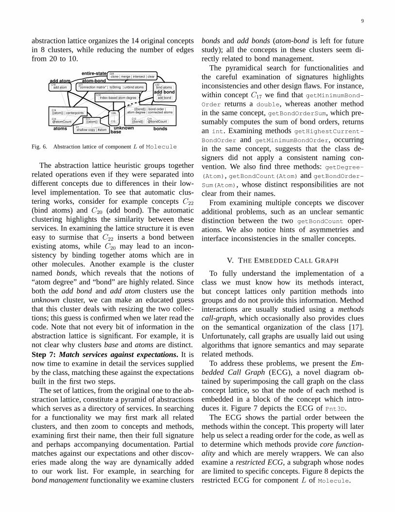
The full lattice of Molecule has only one toplevel concept, so abstracting it would be meaning-less. Instead, we constructed the abstraction latticeof componentL, depicted in Figure 6. An edgebetween clusters indicates that at least one concept(usually a high level one) in the dominating clusterdominates at least one concept in the dominatedcluster; cluster names were chosen manually. The
9
abstraction lattice organizes the 14 original conceptsin 8 clusters, while reducing the number of edgesfrom 20 to 10.
{{bond}} | bond order | atom degree | connected atoms
Index-based atom degree
atoms
{{bond}} @bondCount
"connection matrix" | toString | unbind atoms
add bond
bind atoms
base unknown
add atom
bonds
atom-bond
entire-state
add bond
add atom C18 C21 C22
C19 C20
C17
C12 C13 C14
{{atom}} | centerpoints C16
@atomCount C10
{{atom}} C11
shallow copy | #atom C1
C26
clone | merge | intersect | clear C23
Fig. 6. Abstraction lattice of componentL of Molecule
The abstraction lattice heuristic groups togetherrelated operations even if they were separated intodifferent concepts due to differences in their low-level implementation. To see that automatic clus-tering works, consider for example conceptsC22
(bind atoms) andC20 (add bond). The automaticclustering highlights the similarity between theseservices. In examining the lattice structure it is eveneasy to surmise thatC22 inserts a bond betweenexisting atoms, whileC20 may lead to an incon-sistency by binding together atoms which are inother molecules. Another example is the clusternamed bonds, which reveals that the notions of“atom degree” and “bond” are highly related. Sinceboth theadd bondand add atomclusters use theunknowncluster, we can make an educated guessthat this cluster deals with resizing the two collec-tions; this guess is confirmed when we later read thecode. Note that not every bit of information in theabstraction lattice is significant. For example, it isnot clear why clustersbaseandatomsare distinct.Step 7: Match services against expectations. It isnow time to examine in detail the services suppliedby the class, matching these against the expectationsbuilt in the first two steps.
The set of lattices, from the original one to the ab-straction lattice, constitute a pyramid of abstractionswhich serves as a directory of services. In searchingfor a functionality we may first mark all relatedclusters, and then zoom to concepts and methods,examining first their name, then their full signatureand perhaps accompanying documentation. Partialmatches against our expectations and other discov-eries made along the way are dynamically addedto our work list. For example, in searching forbond managementfunctionality we examine clusters
bondsand add bonds(atom-bondis left for futurestudy); all the concepts in these clusters seem di-rectly related to bond management.
The pyramidical search for functionalities andthe careful examination of signatures highlightsinconsistencies and other design flaws. For instance,within conceptC17 we find thatgetMinimumBond-
Order returns adouble , whereas another methodin the same concept,getBondOrderSum , which pre-sumably computes the sum of bond orders, returnsan int . Examining methodsgetHighestCurrent-
BondOrder and getMinimumBondOrder , occurringin the same concept, suggests that the class de-signers did not apply a consistent naming con-vention. We also find three methods:getDegree-
(Atom) , getBondCount(Atom) andgetBondOrder-
Sum(Atom) , whose distinct responsibilities are notclear from their names.
From examining multiple concepts we discoveradditional problems, such as an unclear semanticdistinction between the twogetBondCount oper-ations. We also notice hints of asymmetries andinterface inconsistencies in the smaller concepts.
V. THE EMBEDDED CALL GRAPH
To fully understand the implementation of aclass we must know how its methods interact,but concept lattices only partition methods intogroups and do not provide this information. Methodinteractions are usually studied using amethodscall-graph, which occasionally also provides clueson the semantical organization of the class [17].Unfortunately, call graphs are usually laid out usingalgorithms that ignore semantics and may separaterelated methods.
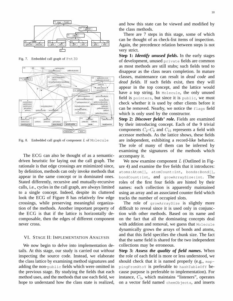
To address these problems, we present theEm-bedded Call Graph(ECG), a novel diagram ob-tained by superimposing the call graph on the classconcept lattice, so that the node of each method isembedded in a block of the concept which intro-duces it. Figure 7 depicts theECG of Pnt3D .
The ECG shows the partial order between themethods within the concept. This property will laterhelp us select a reading order for the code, as well asto determine which methods providecore function-ality and which are merely wrappers. We can alsoexamine arestricted ECG, a subgraph whose nodesare limited to specific concepts. Figure 8 depicts therestrictedECG for componentL of Molecule .
10
setXYZ
getColor setColor getX setX getY setY
setXY
draw Pnt3D
getZ setZ
x color C3 C y z C2 C4 C6
C1
C5
C8
C7
Fig. 7. Embedded call graph ofPnt3D
addBond(int,int,int)
addBond(int,int,int,int)
getBondCount()
contains(Bond)
getBond
getBonds()
getBondCount(Atom)
getBondOrderSum
getConnectedAtoms
getConnectedAtomsVector
getConnectedBonds
getDegree(Atom):int
getHighestCurrentBondOrder
getMinimumBondOrder
removeBond(Bond)
removeBond(Atom,Atom)
removeBond(int)
setBonds
getBondAt
setBondAt
addBonds
addBond(Bond)
removeAllBonds getDegree(int):int
C22
C19
C20
getFirstAtom setAtomAt
getAtomAt
setAtoms
atoms shallowCopy C1
getAtomCount
setAtomCount
contains(Atom)
get2DCenter()
get3DCenter()
getAtoms getAtomNumber
getLastAtom
removeAtom(Atom)
removeAtom(int)
addAtom
atoms:Atom[] atomCount:int growArraySize
C10
bonds bondCount:int
C11
C16
C12
C13 C14
C17
C18
clone
addBonds(double)
getConnectionMatrix
remove
removeAtomAndConnectedBonds
C23
C21
toString
removeAllElements
add
C26
getIntersection
Fig. 8. Embedded call graph of componentL of Molecule
The ECG can also be thought of as a semantic-driven heuristic for laying out the call graph. Therationale is that edge crossings are minimized since,by definition, methods can only invoke methods thatappear in the same concept or in dominated ones.Stated differently, recursive and mutually-recursivecalls, i.e., cycles in the call graph, are always limitedto a single concept. Indeed, despite its clutteredlook the ECG of Figure 8 has relatively few edgecrossings, while preserving meaningful organiza-tion of the methods. Another important property ofthe ECG is that if the lattice is horizontally de-composable, then the edges of different componentnever cross.
VI. STAGE II: I MPLEMENTATION ANALYSIS
We now begin to delve into implementation de-tails. At this stage, our study is carried outwithoutinspecting the source code. Instead, we elaboratethe class lattice by examining method signatures andadding the non-public fields which were omitted inthe previous stage. By studying the fields that eachmethod uses, and the methods that use each field, wehope to understand how the class state is realized,
and how this state can be viewed and modified bythe class methods.
There are 7 steps in this stage, some of whichcan be thought of as check-list items of inspection.Again, the precedence relation between steps is notvery strict.Step 1: Identify unused fields. In the early stagesof development, unusedprivate fields are commonas most methods are still stubs; such fields tend todisappear as the class nears completion. In matureclasses, maintenance can result indead codeanddead fields. If such fields exist, then they willappear in the top concept, and the lattice wouldhave a top string. InMolecule , the only unusedfield is pointers , but since it ispublic , we mustcheck whether it is used by other clients before itcan be removed. Nearby, we notice theflags fieldwhich is only used by the constructor.Step 2: Discover fields’ role. Fields are examinedby their introducing concept. Each of the 9 trivialcomponentsC2–C9 andC15 represents a field withaccessor methods. As the lattice shows, these fieldsare independent, exhibiting a record-like behavior.The role of many of them can be inferred byexamining the signatures of the methods whichaccompany it.
We now examine componentL (Outlined in Fig-ure 4) and examine the five fields that it introduces:atoms:Atom[] , atomCount:int , bonds:Bond[] ,bondCount:int , and growArraySize:int . Theroles of the first four fields are hinted by theirnames: each collection is apparently maintainedusing an array and an associated counter field whichtracks the number of occupied slots.
The role of growArraySize is slightly moredifficult to reveal since it is used only in conjunc-tion with other methods. Based on its name andon the fact that all the dominating concepts dealwith addition and removal, we guess thatMolecule
dynamically grows the arrays of bonds and atoms,and that this field specifies the chunk size. The factthat the same field is shared for the two independentcollections may be erroneous.Step 3: Assess the quality of field names. Whenthe role of each field is more or less understood, weshould check that it is named properly (e.g.,map-
pingFromXtoY is preferable tohashTableOfY be-cause purpose is preferable to implementation). Forinstance,C3, which maintains “listeners”, operateson a vector field namedchemObjects , and inserts
11
objects of typeChemObjectListener . The nameof this field should probably be changed tochem-
ObjectListeners .
Step 4: Investigate fields interdependency. Thelayer-structure of the lattice, and in particular non-empty second-layer concepts (or first-layer conceptswith multiple fields), highlights strong ties betweenfields. In our lattice, the only such concepts areC16
and C17 in the second layer, which reveal thatatoms and atomCount are closely connected, andso arebonds and bondCount . This strengthens ourconviction that the count fields are used to track thenumber of array elements.
While some operations may be more efficientwith this dual-field implementation than with astandardVector , this complicates the class andintroduces new risks. Namely, an important classinvariant is that the number of non-empty entriesin atoms (bonds ) must always equalatomCount
(bondCount ). We make a note to validate this in-variant when we examine the access patterns ofindividual methods.
Step 5:Examine entire-state methods. Some meth-ods, often introduced in upper concepts, are in-tended to operate on the entire state of the classinstance. Their duties often include construction,cloning, serializing, and printing. In this step weidentify these methods, and check whether each ofthem uses all the relevant fields. Exceptions mayindicate that a field is redundant and might beremoved, or that there is an error in the implemen-tation of the method.
We already learned from the outline latticeof Molecule that the title and flags fields arenot initialized or cloned due to a bug. The locationof shallowCopy in the bottom concept indicates anobvious error in its implementation, as no fields areused. In fact, its signature indicates that it is actuallya shallow-clone operation. Examining conceptsC23
andC24 reveals an error inclone since (unlike theconstructors) it only handles the fields dealing withatoms and bonds.
Step 6: Study asymmetries. As we saw inclass Pnt3D , asymmetries in the class lattice canbe very telling, and may indicate incomplete in-terfaces, inappropriate use of inheritance, and otherproblems. Many asymmetries are visible in compo-nentL. For example, a comparison ofC11 andC13
suggests that the interface misses agetFirstBond
method; comparison ofC10 andC14 reveals anotherasymmetry, since there is asetAtomCount method,but no setBondCount .Step 7: Check method access patterns. Now is thetime to meticulously check, based on the informa-tion we collected on field names and roles, that eachmethod uses precisely the fields that it should. Byusing the appropriate read-access and write-accesscontexts we can also check that methods make theexpected kind of access.
Many flaws inMolecule can thus be found. Thesets of atoms and bonds can be completely replaced(using setAtoms and setBonds ) without updatingthe count. Similarly,setAtomCount is exposed tothe user inC10, allowing the invariant to be bro-ken. We also see that the removal of atoms fromthe molecule does not cause incident edges to beremove.
A last step, which we shall not elaborate here,involves examining non-public methods. To doso, we must recalculate the lattice using a contextwhich includes all such methods. We should alsodetermine which methods provide core functionalityand which are wrappers by studying theECG aswell as method metrics [18].
VII. STAGE III: L ATTICE-DIRECTED CODE
INSPECTION
Dunsmore, Roper, and Wood [19] argue thatinheritance, dynamic binding, and small methodsexaggerate delocalization effects whereby makingthe inspection of OO code more difficult than thatof procedural code. Their experiments show thatplanned inspection of OO code can be more effec-tive than an ad-hoc visit. In this section we proposea planned and sensible order for inspecting themethods of a class in isolation. We begin by makingthe case for this order, which will be based onthe lattice structure, and then propose some specificinspection tasks lent by the lattice-directed analysis.
The source code of an OO class may be spreadacross several files, and may have lost any initialorganization. In planning an alternative effectiveorder by which a class is read we hope to readrelated methods appear together, thus increasing theprobability of detecting duplications and increaseopportunities for code sharing.
Another objective is to reduce the mental loadof the human inspector by offering a hierarchical
12
organization and by minimizing the number offorward references. This objective is also servedby following the simple-first rulewhich suggeststhat in the absence of an ordering between items,they should be inspected in an ascending complexityorder. The rationale behind this rule is obvious: thereader has to keep in mind fewer bits of informationon average throughout the reading process.
We propose a lattice-based inspection order, bywhich the code introduced by the methods of eachconcept is read together. The idea is similar toMeyer’s suggestion that methods be organized ingroups by responsibility (global order), and thensorted lexicographically within each group (localorder) [16]. The difference is that we use conceptsfor the responsibility-driven global order, i.e., forautomaticfeature categorization, and method invo-cations for the local order.
Global order: We sort concepts first bycompo-nents, then byascending layer, and finally byclus-ter. The rationale is that methods of one componentnever make reference to the class members, fields ormethods, of another component; similarly, methodsin one layer never refer to members of any higherlayer. The concepts in the same cluster are expectedto be related so we read these together. To choosebetween components, we apply the simple-first rule.
Local order: The embedded call graph is usedto determine the order in which methods of thesame concept are read, so that whenever possi-ble a method is not read before the members towhich it refers. Cycles within a concept and tiesbetween independent methods are broken by thesimple-first rule. Although method simplicity maybe subjective, one can usemethod metrics[18] asa reasonable approximation: simple methods tendto short, contain few branching instructions (lowMcCabe complexity [20]), and invoke few othermethods.
While applying the first two stages of our method-ology we encountered questions which could onlybe answered by the actual code and deferred han-dling them. Examples include the meanings of cer-tain terms or the roles of specific methods and fields,as well as the reasons for various inconsistencies. Inaddition to answering these class-specific question,we give here examples of general inspection tasks,inspired by the concept lattice approach.Task 1: Find duplicate services. If two methodsprovide the same functionality, they are expected
to use the same set of fields regardless of imple-mentation details, and thus to appear in the sameconcept. In our running example, we find thatC17
of Molecule introduces methodsgetDegree(Atom)
and getBondCount(Atom) which supply the sameexact service despite the difference in names andimplementations.Task 2: Identify code-sharing opportunities. Bya similar rationale, if two methods carry out asimilar computation, then these methods are likelyto be in the same or a neighboring concept. Suchmethods may suffer from code replication, espe-cially if they invoke the same methods. For exam-ple, the methodsaddBond(int,int,int) andadd-
Bond(int, int,int,int) in C22 serve differentpurposes but have almost identical implementation,suggesting a refactoring. In some cases, we may beable to make one method a composite of the other.Task 3: Verify that low-level methods are notbypassed. OO-evangelists advocate that we trustoptimizers enough to introduce and use “trivial”methods even for simple operations such as field ac-cess or delegation. Such methods tend to be in low-level concepts. Neglect or a misguided temptation tooptimize are probably the reasons why we found somany cases in which higher level methodsbypassthe supplied trivial methods. In this inspection taskwe search high-level methods for code fragmentswhich could be replaced by (existing) low-levelmethods. One way to do this is to manually feedthe patterns of bypassed methods in low-level con-cepts into astar diagrams[21] engine. We suggestusing theECG and examining the edges emanatingfrom methods in higher concepts and searching formethods which do not invoke methods in the lowerconcepts.
VIII. C ONCLUSIONS ANDFUTURE RESEARCH
This research is the first to applyFCA to theanalysis of individual OO classes. Our main claim isthat the internal structure of a class can be revealedand reasoned about using a concept lattice of the ac-cesses relation between methods and fields. Supportto this claim was provided by a theoretical rationaleand a case study demonstrating its application. Apreliminary user study suggests that programmerscan quickly learn and apply the technique.
The systematic methodology we presented sup-ports the main claim by showing a variety of ways
13
in which non-trivial discoveries can be made in asemi-structured process using this lattice: first bya mere inspection of the interface, then by delvinginto implementation details, and finally by a lattice-directed examination of the source code. Needlessto say, more practical experience is required beforethe methodology can be sealed and released. An-other independent contribution is theembedded callgraph.
We are currently exploring several research di-rections that build upon the foundations laid in thiswork. One such direction is the application of ourtechnique to the design of classes in CASE tools.We believe that the process of adding features toa class, typically carried out by adding features toa list in a UML class hierarchy diagram, can bemore effective with a lattice-based interactive editor.Methods could be associated with fields, formingconcepts, and then additional methods with a relatedfunctionality could be added directly into the appro-priate concept. One advantage of this approach isthat it will reduce the number of cases where severalmethods are added for the same purpose. Anotherresearch direction focuses on the creation of a suiteof class metrics based upon concept lattices andtheir relationship with the cohesion of the class.
In addition to theoretical work, we are currentlyworking on the development of interactive softwaretools and IDE accessories that realize our technique,and in particular a plug-in for theeclipse [22]framework. Work on integration into documentationtools (e.g. [23]) is also carried out.
APPENDIX IPRELIMINARY USER STUDY
In an attempt to provide initial validation to ourhypothesis that concept lattices can assist developersstudying a class, we conducted a limited preliminaryuser study.5 Our study investigated the ability ofnovice developers who were not previously familiarwith concept lattices to rapidly utilize them todiscover errors in theMolecule class. We chose tofocus on error detection because it can be measuredquantitatively in short sessions, unlike more abstractnotions such as understanding. We plan a more ex-tensive user study in the future, which will providestronger validation without the many confoundingissues which are discussed later.
5The study is covered in detail elsewhere [24].
A. Setup and hypotheses
Our subject pool encompassed114 subjects whoreceived token monetary compensation for theirparticipation. The majority were undergraduate stu-dents with limited development experience beyondtheir class work; a minority had industrial devel-opment experience, or were graduate students. Inaddition, only few were previously familiar withthe JAVA language, and the rest were only familiarwith C++. We had to use this limited subject poolbecause of resource limitations, but we intend touse a large group of experiencedJAVA developersfor the larger study.
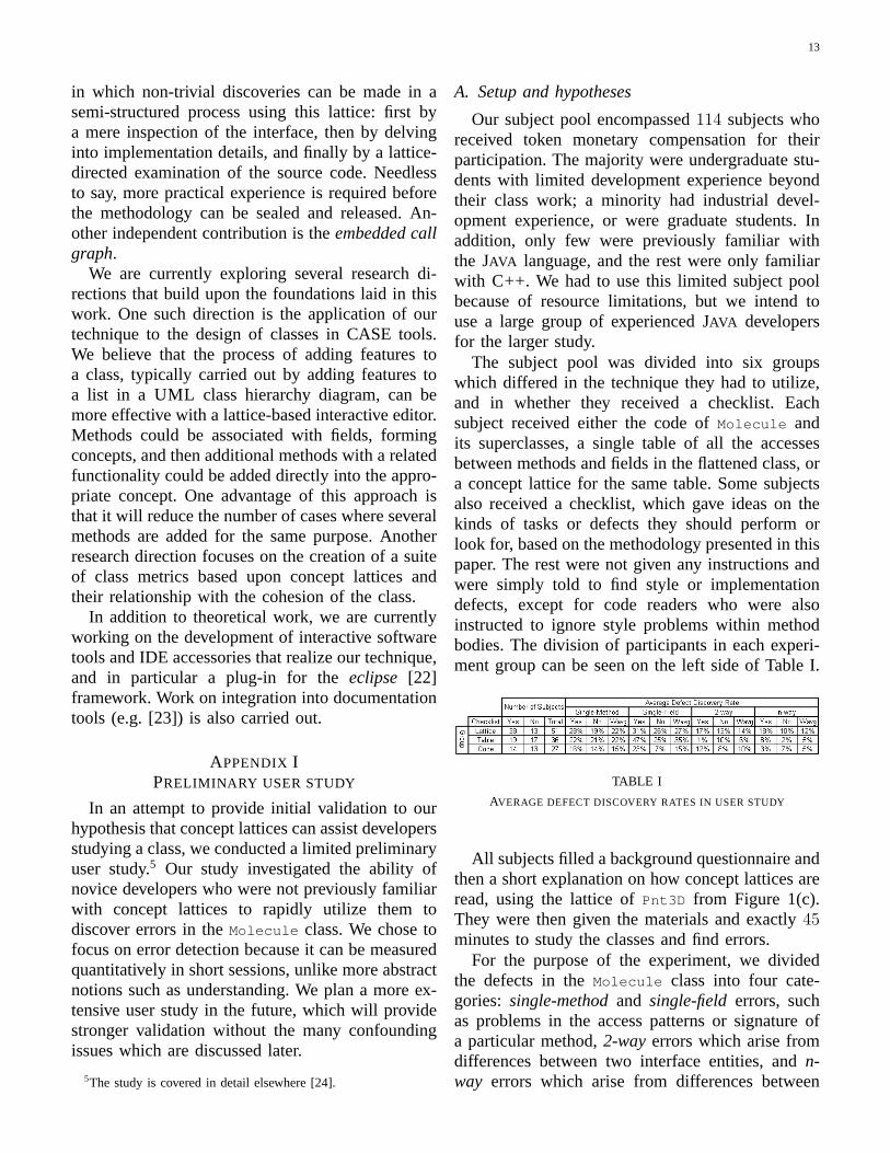
The subject pool was divided into six groupswhich differed in the technique they had to utilize,and in whether they received a checklist. Eachsubject received either the code ofMolecule andits superclasses, a single table of all the accessesbetween methods and fields in the flattened class, ora concept lattice for the same table. Some subjectsalso received a checklist, which gave ideas on thekinds of tasks or defects they should perform orlook for, based on the methodology presented in thispaper. The rest were not given any instructions andwere simply told to find style or implementationdefects, except for code readers who were alsoinstructed to ignore style problems within methodbodies. The division of participants in each experi-ment group can be seen on the left side of Table I.
TABLE I
AVERAGE DEFECT DISCOVERY RATES IN USER STUDY
All subjects filled a background questionnaire andthen a short explanation on how concept lattices areread, using the lattice ofPnt3D from Figure 1(c).They were then given the materials and exactly45minutes to study the classes and find errors.
For the purpose of the experiment, we dividedthe defects in theMolecule class into four cate-gories: single-methodand single-field errors, suchas problems in the access patterns or signature ofa particular method,2-wayerrors which arise fromdifferences between two interface entities, andn-way errors which arise from differences between
14
multiple entities.We had several hypotheses. First, we expected
subjects using the lattices to be more successfulin discovering2-way problems than those in theother modalities. We expected this effect to be evenstronger forn-way defects, because they are lesslikely to be noticed unless the involved methodsare examined together, as occurs thanks to the waythe lattice clusters methods. On the other hand, weexpected the lattice to be less valuable for problemsthat involve a single method or field, and thus be onpar with users of the table. In fact, a table might beslightly more effective for these problems simplybecause most people are familiar with tables. Itis important to remember that the lattice and thetable convey equivalent information, and differencesin performance are likely to be due to cognitivedifferences.
Another hypothesis was that subjects who use thecode will perform poorly on the kinds of defectsstudied here because they will be distracted byproblems in the internal style of the methods, andby the difficulty in ascertaining what fields are usedby each method.
B. Results and analysis
The response forms filled by the subjects allowedthem to list as many errors as they wanted infree form text; we later examined these forms andmarked discovered defects which matched those inour list. This manual interpretation may confoundthe results, but we preferred using free-text re-sponses rather than questionnaires which might leadsubjects to specific defects. For each specific defect,we calculated the percentage of subjects within thesame modality who discovered the same defect.Since there are multiple defects in each category,we averaged the results to obtain an average defectdetection rate within the category.
The results for all modalities and categories ap-pear in Table I. Note that since some categories con-tain more defects, their results are likely to be lowerin absolute numbers than of those with few defects.The results should therefore be compared withinthe category, but between the different modalities.For each category, we also added a column of aweighted average with respect to the use of checklistand the number of subjects in each modality.
The results of this preliminary study confirm ourfirst hypothesis, that the concept lattice is more
effective than other modalities for the detection ofdefects that involve multiple members. This effectwas especially significant forn-way defects withsubjects who did not receive the checklist, indicatingthat the lattice increases the chances of discoveringthese inconsistencies which are otherwise likely togo unnoticed. The similarity in results between tableand lattice users for single-entity defects confirmour second hypothesis, with the lattice at a slightdisadvantage.
The results for the code group, however, didnot fully confirm our third hypothesis. While thosereading the code performed worse than those usingthe tables or lattices, the effect was less significantthan expected, especially for n-way defects. Uponinvestigating the results for specific defect types, wediscovered very high variance between in the resultsof the code group for the defects in each category.It seems that code readers performed exceptionallywell on certain errors, such as with the clearlyerroneous implementation of theclone operationand cases where subsequent placement of relatedmethods made error discovery almost automatic.The good performance on such defects compensatedfor the poor results on the rest of the errors, leadingto relatively high average detection rates.
The results are ambiguous regarding the useful-ness of the checklist. In most cases, they seemto significantly improve the chances of discoveringrelevant errors, but in two modes they actuallydecreased performance. Further study is necessaryto determine the cause for these discrepancies. Onepossibility is that users following the checklist oftendid not reach certain items within the allotted time,skewing the results.
Because of resource limitations we had to use asmall heterogenous subject pool consisting mostlyof undergraduate students without significant devel-opment experience, familiarity with large classes, oror knowledge ofJAVA . We also had to limit sessionsto 45 minutes, which were insufficient for dealingwith a class of this magnitude, as evident fromthe small number of participants who completedall items on the checklist. Nevertheless, the resultsfrom this preliminary user study provide initialconfirmation for our hypothesis and demonstrate thepotential of concept lattices in the study of classes.They also provide incentive for the planned larger-scale study on experienced developers.
15
REFERENCES
[1] L. A. Belady and M. M. Lehman, “Laws of program evolutiondynamics,”IBM Systems Journal, vol. 15, no. 3, pp. 225–252,1976.
[2] M. Mezini, “Maintaining the consistency of class librariesduring their evolution,” inProceedings of the 12th Annual Con-ference on Object-Oriented Programming Systems, Languages,and Applications, Atlanta, Georgia, Oct. 5-9 1997, pp. 1–21.
[3] R. Wille, “Restructuring lattice theory: An approach based onhierarchies of concepts,” inOrdered Sets, I. Rival, Ed. Reidel,1982, pp. 445–470.
[4] G. Snelting, “Reengineering of configurations based on mathe-matical concept analysis,”ACM Trans. on Soft. Eng. & Metho,vol. 5, no. 2, pp. 146–189, 1996.
[5] C. Lindig, “Concept-based component retrieval,” inWorkingNotes of the IJCAI-95 Workshop: Formal Approaches to theReuse of Plans, Proofs, and Programs, Montreal, Aug. 1995,pp. 21–25.
[6] R. Godin and H. Mili, “Building and maintaining analysis-levelclass hierarchies using galois lattices,” inProceedings of the 8th
Annual Conference on Object-Oriented Programming Systems,Languages, and Applications, Washington, DC, USA, Sept. 26- Oct. 1 1993, pp. 394–410.
[7] G. Snelting and F. Tip, “Understanding class hierarchies usingconcept analysis,”ACM Trans. on Programming Languages andSystems, vol. 22, no. 3, pp. 540–582, 2000.
[8] M. Siff and T. Reps, “Identifying modules via concept analy-sis,” in Proceedings of the IEEE International Conference onSoftware Maintenance. Bari, Italy: IEEE Computer SocietyPress, Oct. 1997, pp. 170–179.
[9] A. van Deursen and T. Kuipers, “Identifying objects usingcluster and concept analysis,” inProceedings of the 21st Inter-national Conference on Software Engineering. IEEE ComputerSociety Press, 1999, pp. 246–255.
[10] B. Meyer,Reusable Software: The Base Object-Oriented Com-ponent Libraries, ser. Prentice-Hall Object-Oriented. Prentice-Hall, 1994.
[11] U. Dekel, “Revealing Java class structure with conceptlattices,” Master’s thesis, Department of Computer Science,Technion – Israel Institute of Techology, Haifa, Israel, February2003. [Online]. Available: http://www.uridekel.com/research/Msc/udekelmscthesis.pdf
[12] S. R. Chidamber and C. F. Kemerer, “A metrics suite for objectoriented design,”IEEE Trans. on Software Engineering, vol. 20,no. 6, pp. 476–493, 1994.
[13] G. Booch, Object Solutions. Managing The Object-OrientedProject. Addison-Wesley, 1996.
[14] “Chemistry Development Kit,” reverse engineered withpermission. [Online]. Available: http://cdk.sourceforge.net
[15] C. Steinbeck, D. Gezelter, B. A. Smith, E. Luttmann, and E. L.Willighagen, “The Chemistry Development Kit (CDK): A Javalibrary for structural chemo- and bioinformatics,”Journal ofChemical Information and Computer Sciences, 2003.
[16] B. Meyer,EIFFEL: The Language, ser. Object-Oriented Series.Prentice-Hall, 1992.
[17] M. Lanza and S. Ducasse, “A categorization of classes based onthe visualization of their internal structure: the class blueprint,”in Proceedings of the 16th Annual Conference on Object-Oriented Programming Systems, Languages, and Applications,Tampa Bay, Florida, Oct. 14–18 2001, pp. 300–311.
[18] T. Cohen and J. Y. Gil, “Self-calibration of metrics of Javamethods,” inProceedings of the 26rd International Conferenceon Technology of Object-Oriented Languages and Systems.Sydney, Australia: Prentice-Hall, Nov. 20-23 2000, pp. 94–106.
[19] A. Dunsmore, M. Roper, and M. Wood, “Object-oriented in-spection in the face of delocalisation,” inProceedings of the22nd International Conference on Software Engineering. ACMPress, 2000, pp. 467–476.
[20] T. J. McCabe, “A complexity measure,”IEEE Trans. on Soft-ware Engineering, vol. 2, no. 4, pp. 308–320, Dec. 1976.
[21] R. W. Bowdidge and W. G. Griswold, “Supporting the restruc-turing of data abstractions through manipulation of a programvisualization,”ACM Transactions on Software Engineering andMethodology (TOSEM), vol. 7, no. 2, pp. 109–157, 1998.
[22] “Eclipse project homepage.” [Online]. Available: http://www.eclipse.org
[23] “IBM Java documentation enhancer.” [Online]. Available:http://www.alphaworks.ibm.com/tech/docenhancer
[24] U. Dekel and Y. Gil, “A user study on the use of conceptlattices to detect errors in Java classes,” Department ofComputer Science, Technion – Israel Institute of Techology,Haifa, Israel, Tech. Rep., November 2003. [Online]. Available:http://www.uridekel.com/research/Msc/fcauserstudy.pdf
[25] U. Dekel and Y. Gil, “Revealing class structure with conceptlattices,” in Proceedings of the 10th Working Conference onReverse Engineering, Victoria, B.C., Canada, November 2003,pp. 353–364.