Embed Size (px)
Citation preview

Revealing the nature of the final image in Newton’s experimentumcrucis
Sascha Gruschea)
Physikdidaktik, P€adagogische Hochschule Weingarten, 88250 Weingarten, Germany
(Received 7 July 2014; accepted 4 April 2015)
In his crucial prism experiment, Newton noted the position of the final image, but not its shape or
coloring. Most scholars describe the image as a single-colored representation of the selective
aperture; some report multiple colors. When the experiment is re-enacted as the transformation of a
camera obscura image, it becomes clear that the final image is a rainbow-colored representation of
the outside world. Backward ray tracing enhances Newton’s demonstration of diverse
refrangibility. Using a projector, teachers can easily bring this historical experiment into the
classroom and build a bridge to modern applications in hyperspectral imaging and spectral
encoding. VC 2015 American Association of Physics Teachers.
[http://dx.doi.org/10.1119/1.4918598]
I. INTRODUCTION
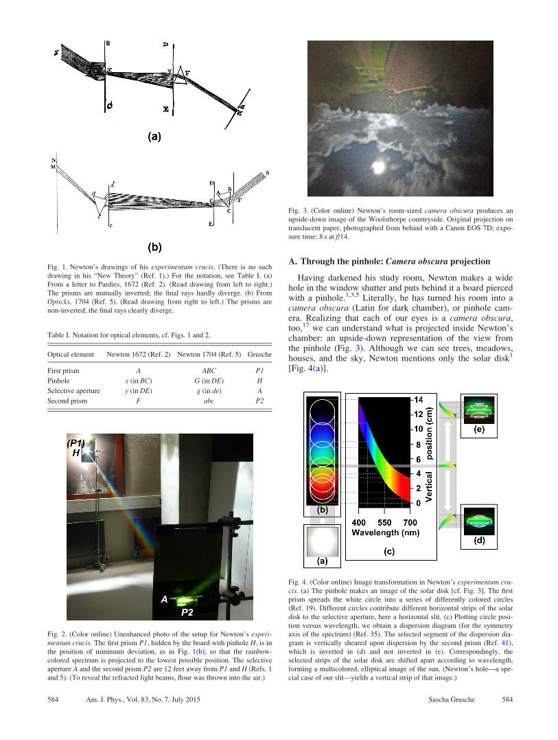
Newton’s experimentum crucis1–5 is a well-known opticsexperiment;6–18 see Fig. 1, cf. Table I and Fig. 2. Newton’s firststep was to refract a narrow beam of sunlight with a prism,obtaining a long, rainbow-colored image.1,3,5 Newton under-stood this spectrum as a vertical series of interlocking solarimages.19 He concluded that sunrays are diverse in the degreeto which they are refracted.1,5 To prove this diverse refrangibil-ity, Newton took a second step: Turning the first prism to andfro, he passed different parts of the spectrum through a selec-tive aperture and a second prism. Looking for diverse refrangi-bility, Newton observed the final image only with regard to itsdiverse positions;1,5 its shape and coloring were irrelevant tohim. In a letter to Pardies,2 Newton wrote that the final imagewas more or less in the shape of the selective aperture, but heleft the exact shape “to be determined by geometricians.”3
Both in his “New Theory”1 and in his Opticks,4 the shape andcoloring of the final image are not described.
Scholars11,20–24 and textbook authors25–27 who describethe experimentum crucis usually believe that the final imageis a single-colored representation of the selective aperture.They claim that the colors of the spectrum are not split up bythe second prism. This scientific belief14 has been handeddown from Newton’s generation to ours.12,18 However, somescientists have observed multiple colors behind the secondprism.28–30 When Newton was challenged to explain thesecolors, he replied that diverse rays come from diverse partsof the sun, and that additional rays could come fromclouds.31 Arguing about the colors of rays, Newton and hiscritics ignored the shape of the final image.
All in all, descriptions of the final image have been incom-plete and inconsistent. Our purpose here is to clarify theshape and coloring of the final image. To this end, we willreconsider the entire imaging process.
Newton’s ray drawings2,5 indicate this imaging process(Fig. 1): Sunrays are refracted, selected, and refracted again.Still, the shape of the final image is unclear because the thirddimension is missing. We cannot even assign colors to therays because Newton did not draw to scale. To achieve thecorrect proportions, we would need a sketch that is almostlife-sized. Thus, a ray-based approach seems impractical.
Instead, we will use an image-based approach,9,32,33 whichis outlined in Sec. II. In Secs. III and IV, we apply this
approach to the experimentum crucis. In Sec. V, we turn toan equivalent experiment to validate our view of the finalimage. In Sec. VI, the teacher will find ways to bring theexperimentum crucis into the classroom, and in Sec. VII, wehighlight the results and implications of our image-basedapproach.
II. PRINCIPLES OF AN IMAGE-BASED APPROACH
To enjoy the benefits of an image-based approach, we willfollow its three major principles (cf. Refs. 9, 32, and 33):
Principle I: Watch how the phenomenon changes as the ex-perimental conditions change.Principle II: Think in terms of images instead of light rays.Principle III: Draw rays only to represent lines of sight, nottrajectories of light.
If we apply the first principle successfully, our insightswill be systematic and based on visual experience. Yet howcan we change the experimental conditions without changingNewton’s experimental setup? We will achieve this by start-ing with only one optical element, and then adding the otherelements, one by one. Newton’s description starts with prismP1 (Fig. 2), but we will start differently.34
For a direct application of the second principle, we willbegin with the pinhole H to produce a concrete image. Then,we will put the other elements at their designated places,watching how they successively change the initial imageinto the final image. Thus, we will see more than Newtonsaw, and gain a holistic understanding of the imaging pro-cess. Even Newton thought in terms of images when explain-ing the spectrum,19 but he thought in terms of rays whendiscussing the light behind the selective aperture.1,3,5,31
The third principle allows us to interpret the imaging pro-cess in terms of rays, without speculating about the nature oflight.9 However, before we introduce any rays, we will thinkeverything through in terms of images.
III. FROM INITIAL TO FINAL IMAGE
To understand the shape and coloring of the final image,we will re-enact Newton’s experimentum crucis as the crea-tion and transformation of a camera obscura projection.
583 Am. J. Phys. 83 (7), July 2015 http://aapt.org/ajp VC 2015 American Association of Physics Teachers 583
A. Through the pinhole: Camera obscura projection
Having darkened his study room, Newton makes a widehole in the window shutter and puts behind it a board piercedwith a pinhole.1,3,5 Literally, he has turned his room into acamera obscura (Latin for dark chamber), or pinhole cam-era. Realizing that each of our eyes is a camera obscura,too,17 we can understand what is projected inside Newton’schamber: an upside-down representation of the view fromthe pinhole (Fig. 3). Although we can see trees, meadows,houses, and the sky, Newton mentions only the solar disk1
[Fig. 4(a)].
Fig. 1. Newton’s drawings of his experimentum crucis. (There is no such
drawing in his “New Theory” (Ref. 1).) For the notation, see Table I. (a)
From a letter to Pardies, 1672 (Ref. 2). (Read drawing from left to right.)
The prisms are mutually inverted; the final rays hardly diverge. (b) From
Opticks, 1704 (Ref. 5). (Read drawing from right to left.) The prisms are
non-inverted; the final rays clearly diverge.
Table I. Notation for optical elements, cf. Figs. 1 and 2.
Optical element Newton 1672 (Ref. 2) Newton 1704 (Ref. 5) Grusche
First prism A ABC P1
Pinhole x (in BC) G (in DE) H
Selective aperture y (in DE) g (in de) A
Second prism F abc P2
Fig. 2. (Color online) Unenhanced photo of the setup for Newton’s experi-mentum crucis. The first prism P1, hidden by the board with pinhole H, is in
the position of minimum deviation, as in Fig. 1(b), so that the rainbow-
colored spectrum is projected to the lowest possible position. The selective
aperture A and the second prism P2 are 12 feet away from P1 and H (Refs. 1
and 5). (To reveal the refracted light beams, flour was thrown into the air.)
Fig. 3. (Color online) Newton’s room-sized camera obscura produces an
upside-down image of the Woolsthorpe countryside. Original projection on
translucent paper, photographed from behind with a Canon EOS 7D; expo-
sure time: 8 s at f/14.
Fig. 4. (Color online) Image transformation in Newton’s experimentum cru-cis. (a) The pinhole makes an image of the solar disk [cf. Fig. 3]. The first
prism spreads the white circle into a series of differently colored circles
(Ref. 19). Different circles contribute different horizontal strips of the solar
disk to the selective aperture, here a horizontal slit. (c) Plotting circle posi-
tion versus wavelength, we obtain a dispersion diagram (for the symmetry
axis of the spectrum) (Ref. 35). The selected segment of the dispersion dia-
gram is vertically sheared upon dispersion by the second prism (Ref. 41),
which is inverted in (d) and not inverted in (e). Correspondingly, the
selected strips of the solar disk are shifted apart according to wavelength,
forming a multicolored, elliptical image of the sun. (Newton’s hole—a spe-
cial case of our slit—yields a vertical strip of that image.)
584 Am. J. Phys., Vol. 83, No. 7, July 2015 Sascha Grusche 584

B. Through the first prism: Dispersed image
Next, Newton puts a prism in front of the pinhole.1,3,5
Still, we have a camera obscura projection. Again, it corre-sponds to the view from the pinhole.17 From the pinhole,Newton would see the landscape through the prism, now.Thus, he would see a blurry, multicolored image of the land-scape. If we look through the pinhole and prism with mono-chromatic filters, we see sharp images of the landscape.35
These images are similar in shape but different in color andposition. Hence, the blurry prismatic image comprises a se-ries of sharp, monochromatic images.35,36
Accordingly, we interpret the sun’s spectrum as a series ofdifferently colored circles19 [Fig. 4(b)]. Having fixed ourequilateral crown-glass prism in the position of minimumdeviation,1,10,14 we trace the outline of the spectrum37,38 on apiece of cardboard 12 feet away.1,5 Within this outline, wetrace individual images of the sun where we see themthrough monochromatic filters.37 As the spectrum is movingaccording to the sun, we need to continually re-position thecardboard, until we have drawn the circles for all filters (forwavelengths 400 nm, 450 nm, 500 nm, 550 nm, 600 nm,650 nm, and 700 nm). Refining the drawing in several itera-tions,37 we obtain an accurate picture of how the prism shiftsthe solar image to different places for different wavelengths[Figs. 4(b) and 4(c)].
C. Through the selective aperture: Spectrally encoded
image
Newton’s projection screen for the spectrum contains aselective aperture in the form of a small hole.1,3,5 To movethe spectrum up and down across the hole, he turns the firstprism to and fro. He needs to hurry1,5 because the azimuthalmotion of the sun causes its spectrum to run sideways acrossthe hole within a few minutes.
Seeing that the horizontal position of the selective apertureis arbitrary, we will use a horizontal slit6,12,16,17 instead ofthe hole. Later on, we will treat Newton’s hole as a specialcase. Using a slit, we need not even turn the first prism: Thealtitudinal motion of the sun causes all parts to successivelygo through the slit within about ten minutes.
Remember that Newton’s spectrum is a series of differ-ently colored circles.19 Suppose the slit admits the green partof the spectrum, as in Figs. 2 and 4(b). In this case, thegreenish-blue circle (seen through the 500 nm filter) contrib-utes its lower part to the slit, the orange circle (seen throughthe 600 nm filter) contributes its upper part, while intermedi-ate circles contribute intermediate parts. On the wall behindthe selective aperture, we see a single-colored slit image.Through monochromatic filters, we can see that this slitimage is composed of different horizontal strips of differ-ently colored circles.
To speak in modern terms, the whole disk of the sun isspectrally encoded in the slit image [cf. Figs. 4(b) and 4(c)].Spectral encoding is the representation of one spatial dimen-sion in the wavelength dimension. This process has beenapplied in lensless microscopy,39 fiber-based endoscopy,40
and surround-view video projection41 (see Sec. V B).Moreover, spectral encoding underlies spatiospectral scan-ning42—a technique for hyperspectral imaging, whereby thechemical composition of an object is revealed.
D. Through the second prism: Spectrally decoded image
To refract the selected light, Newton places a secondprism behind the selective aperture.1,3,5 Directly behind thesecond prism, where the horizontal strips of the solar diskare still overlapping, we still see a single-colored slit image.The further we move the final projection screen from the sec-ond prism, the further the horizontal strips move apart. Thestrips are arranged according to wavelength. If the secondprism is inverted relative to the first, as in Fig. 1(a), the stripsare arranged in the original order, yielding an image of thesun that is upside-down like the initial image [Figs. 4(d) and5(a)]. If the second prism is non-inverted, as in Fig. 1(b), thestrips are arranged in reverse order, yielding a blurrier, right-side-up image [Figs. 4(e) and 5(b)]. With a non-invertedprism, the shift among the strips is equal and opposite to theshift with an inverted prism (assuming that the prism isalways in the position of minimum deviation, and that thedistance from the prism to the final image is the same). Yetwith an inverted prism, the final image is narrower becausethe upper part of the lower circle and the lower part of theupper circle from the spectrum are hidden inside the finalimage [Fig. 4(d)]. In both cases, the final image is a multicol-ored, elliptical image of the sun.
The final image is especially impressive when the sun isrising or setting behind barren trees. Within about tenminutes, we can watch the solar disk wander through all thecolor bands, revealing the silhouettes of branches and twigs.Evidently, the final image is a rainbow-colored representa-tion of an entire scene, the brightest part of which is the sun(cf. Appendix). If we reduce our slit6,12,16,17 to Newton’shole,1,3,5 we only see a vertical strip of that scene.
Fig. 5. Three overlaid photos of the final image at different times t. With a
horizontal slit as the selective aperture—and with both prisms fixed—one
can watch a rainbow-colored “motion picture” of the rising sun. The projec-
tion screen is vertically placed 4 feet behind the second prism. (a) With
prisms inverted as in Fig. 1(a), the rising sun seems to set. (b) With non-
inverted prisms, as in Fig. 1(b), the sun appears less sharp. Photographed
with a Panasonic DMC-FZ50; exposure time: 2 s at f/11.
585 Am. J. Phys., Vol. 83, No. 7, July 2015 Sascha Grusche 585

IV. FROM IMAGES TO RAYS
Now that we have understood the experimentum crucis interms of images, we may interpret it in terms of rays9 thatconnect object points and image points.
Newton traced rays forward from the sun to the final image,as shown in Fig. 1. However, this mechanistic approach ledhim to idealize the sunrays as parallels, to ignore the sun’s sur-roundings, and to presuppose diverse refrangibility.
For a simpler, more accurate, and less speculativeapproach, we exploit the principle of reversibility (Axiom IIIin Opticks4): Tracing rays backward from image points toobject points, we automatically follow only the relevant rays(Fig. 6). These Euclidean lines of sight9 directly support theNewtonian notion of differently refrangible rays. Moreover,a symmetry emerges that is missing in Newton’s forward raytracing: the final image must always be a rainbow-coloredrepresentation of the outside world.
To make the final image single-colored, Newton devised alens-enhanced version43 of his experimentum crucis.12,18
Even in this experiment, the final image represents the out-side world, as I will show elsewhere.
V. WHAT NEWTON DID NOT SEE
A. “One sees only what one knows”—Goethe
Did Newton know that the final image represents the out-side world? For a definitive answer, we turn to a relatedexperiment. In his Opticks, directly after the experimentumcrucis, Newton describes a thread experiment44 [Fig. 7, cf.Fig. 2]. He uses a white thread as the selective aperture, putsthe first prism behind the pinhole and takes up the secondprism to look through it toward the thread.
The thread experiment works like the experimentum crucis(cf. Fig. 4): The pinhole produces a white solar image; the firstprism spreads the white circle out into a series of differentlycolored circles; the selective aperture receives different stripsof these circles; the second prism shifts these image strips.45
To compare the shift for two different colors, Newton adds apinhole H0 and prism P10 to get a second spectrum.44
Now that Newton’s selective aperture is linear, he shouldsee through his prism a pair of ellipses. However, he doesnot. He describes the final images as straight lines, and evendraws them thus [Fig. 8(a)].44 It lies in the nature of sciencethat “meaningful observation is not possible without pre-existing expectation.”14 Apparently, Newton is blinded byhis ray-based preconceptions. His supporter Desaguliersblindly follows him [Fig. 8(b)].31 Both see the thread“divided into two.”31,44 The Royal Society agrees.31
With our image-based approach, we know that the finalprism does more than just divide: It destroys the image ofthe thread, creating solar images instead (Fig. 9). These ellip-tical images become circular as we approach the prisms P1and P10. Even Goethe, who repeated and criticized all ofNewton’s experiments, failed to see these multicoloredimages of the sun.46
B. A brighter version of Newton’s thread experiment
So far, we have only seen images of the sun. Can we seesunlit objects, too? To make the final image as bright as
Fig. 6. Backward ray tracing (from points in the final image to the corre-
sponding object points); (a) is the counterpart to Fig. 1(a) and (b) is the
counterpart to Fig. 1(b). The blue line of sight (B) goes to the uppermost
part of the scene, the red line of sight (R) goes to the lowermost part of the
scene; intermediate lines (omitted) go to intermediate parts. We infer that
the angle between rays R and B at P1 equals the field of view (Ref. 42), and
that rotation of P1 effects spatiospectral scanning (Ref. 42), whereby the
bright solar image is moved through the otherwise dark color bands on the
final screen.
Fig. 7. (Color online) Unenhanced photo of the setup for Newton’s thread
experiment. (a) Pinholes H and H0 each produce a camera obscura image of
the outside world (note the double images of trees and clouds on the pillar).
The two solar images are dispersed by prisms P1 and P10 into two spectra.
At a distance of 12 feet, the selective aperture A—here a thread—receives
one color from each spectrum. The viewer, semitransparent in this long-
exposure photo, views the thread through prism P2, cf. Fig. 8(b). (b) H, H0
and P1, P10.
Fig. 8. Newton’s and Desaguliers’s misinterpretations of the final image in the
thread experiment. (a) Newton sees the thread “divided into two parallel Threds”
(Ref. 44). (b) Desaguliers repeats the experiment with a paper strip instead of the
thread. Likewise, he sees the paper strip “divided into two” (Ref. 31).
586 Am. J. Phys., Vol. 83, No. 7, July 2015 Sascha Grusche 586

possible, we bring the prisms closer to the thread, andreplace the thread with a linear translucent screen to beviewed from behind (Fig. 10, cf. Ref. 41). Direct-visionprisms have a larger dispersion angle than simple ones,allowing us to double the field of view to about 5�.41,42 Asexpected, the final image is a rainbow-colored image of thesunlit scene (Fig. 11).
Even Newton and Goethe—albeit with simple prisms—could have done such an experiment. However—apparentlyunaware that the final image represents the outside world—they did not.
VI. BRINGING THE EXPERIMENTUM CRUCIS INTO
THE CLASSROOM
A. Camera obscura projection or video projection
The experimentum crucis is easy to re-enact in the class-room. Moreover, one can build a dollhouse version at a scaleof 1:10, take it outside into the sunshine, observe the
spectrum and a pea-sized final image of the sun, and bringthe dollhouse back inside. However, the experimentum cru-cis and its dollhouse version only work on sunny days.
Alternatively, teachers may simulate the camera obscuraprojection with a video projector (cf. Ref. 11). With the firstprism before the projector, the rest of the setup can be a rep-lica of the original experiment.
B. A modern application: Projected-ImageCircumlineascopy (PICS)
Having replaced the scene and pinhole with a video pro-jector, the teacher can translate the historical experiment intoa modern application, called Projected ImageCircumlineascopy (PICS).41 A video is projected through thefirst prism and onto a white thread, or, more conveniently, anuncooked spaghetti noodle. Sitting in a circle around the spa-ghetti, students can view through the second prism a sharp,rainbow-colored version of the video.41 This projectionmethod epitomizes the nature of the final image in Newton’sexperimentum crucis: It is a rainbow-colored representationof the initial image.47
VII. CONCLUSION
For the first time in the discourse on Newton’s experimen-tum crucis, we have revealed the nature of the final image: itis a rainbow-colored representation of the outside world. Ifthe selective aperture is a slit, the final image is two-dimensional; if the slit is reduced to a hole, only a verticalstrip of this image remains. When Newton turned his prismto and fro, he unknowingly scanned up and down the land-scape before his window.
Newton interpreted the final image as a representation ofthe selective aperture. His friend Desaguliers, and even hisenemy Goethe, perpetuated this interpretation. Evidently,Newton’s conceptual change from images to rays was pre-mature, and scientific belief hindered scientific insight. Still,our image-based approach only serves to underline, notundermine, the validity of Newton’s demonstration ofdiverse refrangibility.
Because the final image is always rainbow-colored, thelensless setup for Newton’s experimentum crucis is not amonochromator. Instead, the setup is an imaging system. Wehave identified the imaging principle as spectral coding. This
Fig. 9. Re-enactment of Newton’s thread experiment (cf. Fig. 7). White
thread illuminated with blue and yellow from prisms P1 and P10. (b)
Viewed through prism P2, the final image is in the form of two ellipses,
each representing the sun. (Only if the first two prisms are too far off the
position of minimum deviation, the ellipses look like lines.) Photographed
with a Panasonic DMC-FZ50; exposure time: 8 s at f/11.
Fig. 10. (Color online) Photo of the setup for a brighter version of Newton’s
thread experiment [cf. Fig. 7. (a)]. The outside world is projected through
pinhole H and direct-vision prism P1 onto a translucent projection screen.
Black paper with a 4 mm wide slit is taped onto the screen to obtain a trans-
lucent version A of Newton’s thread. The distance from H to A is 1.5 m.
Through direct-vision prism P2, a camera photographs toward A from a dis-
tance of 1 m. For maximum image sharpness, P1 is not inverted relative to
P2 (Ref. 41). (b) Pinhole H (made triangular to show that the shape of the
hole does not significantly affect the projected image) and prism P1.
Fig. 11. Images of the basilica of Weingarten (upside-down like the initial
camera obscura image). (a) Photo taken with a Panasonic DMC-FZ50
behind P2 (cf. Fig. 10). Although the exposure was 60 s (at f/11), the spectral
image itself was visible to the unaided eye, as long as the sun was shining
bright. (b) Direct view (rotated).
587 Am. J. Phys., Vol. 83, No. 7, July 2015 Sascha Grusche 587

principle is nowadays used in fields such as biomedicalimaging and remote sensing. Accordingly, teachers can builda bridge between the historical experiment and modernapplications.
ACKNOWLEDGMENTS
In 2010, Professor Dr. Johannes Grebe-Ellis and Dr.Matthias Rang sparked my interest in the experimentumcrucis, and Florian Theilmann invited me to explore spectrawith him. In January 2014, four dozen 10th and 11th gradestudents from the Einstein Gymnasium in Potsdam/Germanyjoined my project Newton versus Grusche, which formed thebasis of this manuscript. One of the students, Henriette Bast,helped improve the text. Ann Blackett and assistants atWoolsthorpe Manor provided the photo for Fig. 3.Alexander Neub built a dollhouse version with me. AnneSmith revised the language. The two anonymous reviewersinspired me to improve the argument and illustrations.
APPENDIX: PROJECTING A SOLAR ECLIPSE WITH
THE EXPERIMENTUM CRUCIS
On 20 March 2015, between about 9:30 and 11:50 a.m.,there was a solar eclipse over Germany. To project the par-tial eclipse, I used Newton’s experimentum crucis; theimages are shown in Fig. 12.
a)Electronic mail: [email protected]
1I. Newton, “A letter […] containing his new theory of light and colors
[…],” Philos. Trans. 6, 3075–3087 (1671).2I. Newton, “Mr. Newtons answer to the foregoing letter,” Philos. Trans. 7,
4014–5018 (1672).3An English translation of Ref. 2 appeared in The PhilosophicalTransactions of the Royal Society of London, from […] 1665, to the Year1800, Abridged, Volume I (Baldwin, London, 1809), pp. 740–743.
4I. Newton, Opticks: Or, A Treatise of the Reflexions, Refractions,Inflexions and Colours of Light, 4th ed. (Dover Publications, Mineola,
1979).
5In Ref. 4, the experimentum crucis, although not labeled as such, appears
in Book I, Part I, Exp. 6.6Lord Rayleigh, “Newton as an experimenter,” Proc. R. Soc. London Ser.
A 131, 224–230 (1943).7R. S. Westfall, “The development of Newton’s theory of color,” Isis 53(3),
339–358 (1962).8J. A. Lohne, “Experimentum crucis,” Notes Rec. Roy. Soc. 23(2),
169–199 (1968).9T. Holtsmark, “Newton’s experimentum crucis reconsidered,” Am. J.
Phys. 38, 1229–1235 (1970).10A. I. Sabra, Theories of Light, from Descartes to Newton (Cambridge U.P.,
Cambridge, 1981).11D. H. Towne, “Teaching Newton’s color theory firsthand,” Am. J. Phys.
61, 113–118 (1993).12A. E. Shapiro, “The gradual acceptance of Newton’s theory of light and
color, 1672–1727,” Persp. Sci. 4, 59–140 (1996).13J. Worrall, “The scope, limits, and distinctiveness of the method of ‘deduc-
tion from the phenomena’: Some lessons from Newton’s demonstrations
in optics,” Brit. J. Philos. Sci. 51, 45–80 (2000).14R. d. A. Martins and C. C. Silva, “Newton and colour: The complex inter-
play of theory and experiment,” Sci. Educ. 10(3), 287–305 (2001).15R. C. Crease, “Experimentum crucis: Newton’s decomposition of sunlight
with prisms,” in The Prism and the Pendulum. The Ten Most BeautifulExperiments in Science (Random House, New York, 2003), pp. 58–76.
16M. Rang, “Mehrfachanwendung von Spiegelspaltblenden und Prismen—
eine moderne Form von Newtons experimentum crucis,” in Didaktik derPhysik. Fr€uhjahrstagung Bochum, edited by H. Gr€otzebauch and V.
Nordmeier (PhyDid, Berlin, 2009), pp. 1–12, <http://www.experimentum-
lucis.de/Paper/DPG09-Tagung_Rang.pdf>.17M. Rang and O. M€uller, “Newton in Gr€onland,” Philos. Nat. 46, 61–114 (2009).18Y. Takuwa, “The historical transformation of Newton’s experimentum cru-
cis: Pursuit of the demonstration of color immutability,” Hist. Sci. 23,
113–140 (2013); available at researchmap.jp/?action=cv_download_
main&upload_id=64609.19Book I, Part I, Exp. 5, Illustration in Ref. 4.20According to Ref. 9, a selected ray is refracted “without any sign of
dispersion.”21According to Ref. 14, “if one separates from the coloured spectrum a nar-
row beam of light, its colour will not be changed by a second prism”.22Grebe-Ellis identifies the hole H as a point source, concluding that the final
projection screen should display a relatively sharp and single-colored
shadow image of the selective aperture, see J. Grebe-Ellis, “Bild und
Strahl in der Optik Newtons,” in Ostwalds Klassiker der exaktenWissenschaften, Band 20, edited by J. Grebe-Ellis (Harri Deutsch,
Frankfurt am Main, 2011), pp. XII–XVIII.
Fig. 12. (Color online) The final image in Newton’s experimentum crucis, produced during a solar eclipse over Weingarten/Germany on 20 March 2015. (The
selective aperture was a horizontal slit.) Photos taken with a Panasonic DMC-FZ50, exposure time: 1 s at f/3.2.
588 Am. J. Phys., Vol. 83, No. 7, July 2015 Sascha Grusche 588

23In a video inspired by Ref. 9, the audio track pretends that “the hue
remains unchanged” behind the second prism, while the film itself betrays
additional hues, see Pehr S€allstr€om, Monochromatic Shadow Rays. A FilmAbout Experiments on the Rehabilitation of Darkness (edition waldorf,
Stuttgart, 2010).24O. L. M€uller, Mehr Licht. Goethe mit Newton im Streit um die Farben (S.
Fischer Verlag, Frankfurt am Main, 2015).25Newton “showed that a small portion of the spectrum could not be spread
into any other colors by passing the light through a second prism,” see
Contemporary College Physics. Third Edition, 2001 Update, edited by E.
Jones and R. L. Childers (McGraw-Hill, New York, 2001).26“Newton […] passed a pencil of sunlight through a prism. The emergent
light fanned out into a spectrum or rainbow of colors …. These spectral
colors were not further dispersed by additional prisms,” writes M. Katz,
Introduction to Geometrical Optics (World Scientific, Singapore, 2004).27Let me translate a passage from the classic of German university text-
books: “The rays going [from the yellow part of Newton’s spectrum
through a hole and] through P2 to the second screen… were not pulled
apart into a colored band again, but created only a yellow spot.” The cap-
tion to the accompanying schematic reads: “Non-decomposability of col-
or.” See H.-J. Eichler, “Dispersion und Absorption des Lichtes,” in
Bergmann—Schaefer Lehrbuch der Experimentalphysik, Band 3: Optik,
10. Auflage, edited by H. Niedrig (Walter de Gruyter, Berlin, 2004), pp.
189–300.28The German poet Goethe observes that the second refraction adds reddish
and bluish fringes to the yellow part of the spectrum, see paragraph 137 in J.
W. v. Goethe, Farbenlehre, Band 3: Enth€ullung der Theorie Newtons, edited
by G. Ott and H. O. Proskauer (Verlag Freies Geistesleben, Stuttgart, 1979).29As elaborated in Refs. 12 and 18, many scholars falsely assume that the
experimentum crucis was to prove color immutability. Newton himself
stated in his lectures that he found yellow rays among the red, and blue
rays among the violet. Still, Lucas was surprised to find red rays among
the violet, and Mariotte, who performed a similar experiment, questioned
Newton’s theory when he found violet rays among the red, as well as red
rays among the violet.30When I involved Rang (cf. Ref. 17) in a Socratic dialogue, he character-
ized the final image as a blurry, multi-colored version of a part of the spec-
trum. Only when asked what would be seen, he came to the same
conclusion as me, see Sec. III D.31I. Newton and J. T. Desaguliers, “An account of some experiments of light
and colours,” Philos. Trans. 29, 433–447 (1714).32J. Grebe-Ellis, “Ph€anomenologische Optik: eine ‘Optik der Bilder.’ Teil 1:
Erkenntnistheoretische, experimentiermethodische und didaktische
Merkmale eines nichtreduktionistischen Zugangs zur Optik,” chim.
did. 32, 137–186 (2006); available at www.physikdidaktik.uni-wuppertal.
de/fileadmin/physik/didaktik/Forschung/Publikationen/Grebe-Ellis/Bartholinus_
Huygens_2011.pdf.33G. Maier, An Optics of Visual Experience (Adonis Press, Hillsdale, 2011).34Arranging the optical elements in the spatial sequence P1–H–A–P2, one
can choose from N ¼ 4! ¼ 24 temporal sequences. Ours is probably easiest
to follow.35F. Theilmann and S. Grusche, “An RGB approach to prismatic colours,”
Phys. Educ. 48, 750–759 (2013).36Newton sketches and explains this in Optica, Part II, Lecture 12, paragraph
[104] in I. Newton, The Optical Papers of Isaac Newton, Volume I. TheOptical Lectures 1670-1672, edited by A. Shapiro (Cambridge U.P.,
Cambridge, 2010).37Newton traces only the superficial structure of the spectrum, see Book I,
Part II, Exp. 7 in Ref. 4. Nonetheless, he sketches his conceptualization of
the underlying structure as a series of circles, see note 19.38With an equilateral flint-glass prism, our spectrum was 10 cm longer. On a
white sheet of paper or white cloth, the spectrum was another 70% longer
because the whitening agents made ultraviolet visible as blue.39A. Schwarz, A. Weiss, D. Fixler, Z. Zalevsky, V. Mic�o, and J. Garc�ıa,
“One-dimensional wavelength multiplexed microscope without objective
lens,” Opt. Commun. 282, 2780–2786 (2009).40M. Merman, A. Abramov, and D. Yelin, “Theoretical analysis of spectrally
encoded endoscopy,” Opt. Express 17, 24045–24059 (2009).41S. Grusche, “Spectral synthesis provides two-dimensional videos on a one-
dimensional screen with 360�-visibility and mirror-immunity,” Appl. Opt.
53, 674–684 (2014).42S. Grusche, “Basic slit spectroscope reveals three-dimensional scenes
through diagonal slices of hyperspectral cubes,” Appl. Opt. 53, 4594–4603
(2014).43Book I, Part I, Exp. 12 in Ref. 4.44Book I, Part I, Exp. 7 in Ref. 4.45Inspecting the illuminated thread through a prism is analogous to projec-
ting an illuminated slit through a prism because the retina is analogous to a
projection screen and there is a non-zero distance between the prism and
the projection screen, cf. Ref. 41.46To explain why the blue and red parts of the thread move apart, Goethe
passes several parts of the spectrum through a perforated board, seeing
through his prism that the parts behave like the whole: The spectrum is
stretched so that its parts are moved apart. However, in the thread experi-
ment, even Goethe sees lines, see paragraphs 138–149 in the reference
from note 28.47Admittedly, the final image is also a representation of the selective aper-
ture, but only to the extent to which a camera obscura projection is a rep-
resentation of the pinhole.
589 Am. J. Phys., Vol. 83, No. 7, July 2015 Sascha Grusche 589