Embed Size (px)
Citation preview

Revelation of the effect of structural heterogeneity on microplasticityin bulk metallic-glasses
Yong Yang,a) Jianchao Ye, and Jian LuThe Department of Mechanical Engineering, The Hong Kong Polytechnic University, Hung Hom,Kowloon, Hong Kong, People’s Republic of China
Qing WangThe Department of Mechanical Engineering, The Hong Kong Polytechnic University, Hung Hom,Kowloon, Hong Kong, People’s Republic of China; and The Institute of Materials Science,The University of Shanghai, 200072 Shanghai, People’s Republic of China
Peter K. LiawThe Department of Material Science and Engineering, The University of Tennessee, Knoxville,Tennessee 37996-2200
(Received 22 July 2009; accepted 2 November 2009)
In this article, the shear-banding behavior in bulk metallic-glasses (BMGs) is studiedusing a focused ion beam (FIB)-based nanoindentation method, which involvescylindrical nanoindentation of a FIB-milled BMG microlamella and is capable ofrevealing the subsurface shear-band patterns down to the submicron scale. The results ofthe current study on a Zr-based BMG clearly show that short shear bands, with the lengthsof a few hundred nanometers, could be severely kinked before growing into a longer one,which implies that structural heterogeneity plays an important role in the microplasticityof BMGs. Furthermore, through the three-dimensional finite-element simulationcombined with the theoretical calculation based on the Mohr–Coulomb law, it is foundthat the yield strengths exhibit a large scatter as a consequence of the structuralheterogeneity when microplasticity occurs in the Zr-based BMG, which is consistent withour recent findings obtained from the microcompression experiments.
I. INTRODUCTION
Bulk metallic glasses (BMGs) have been attracting agreat deal of interest of materials scientists since 1960,1
when it was first demonstrated that amorphous metalscould be synthesized through the rapid quenching ofsupercooled liquids. In the absence of crystalline defects,such as dislocations and grain boundaries, BMGs aresuperior to their crystalline counterparts in yield strengthsand corrosion resistance.2,3 The unique combination of themechanical properties of BMGs make them an excellentclass of materials for a variety of applications, includingsports and luxury goods, electronics, medical devices, andnational defense.4 However, this class of materials usuallyexhibits limited ductility at room temperature. When plas-ticity sets in, the lack of strain hardening gives rise to thestrain localization into a few narrow shear bands withinthe BMGs. The subsequent catastrophic propagation of theshear bands ultimately results in the brittle-like fracture.
The inelastic deformation in BMGs originates fromthe existence of the atomic clusters in an amorphousstructure, which can undergo shear transformations much
easier than their surroundings under mechanical load-ings. In the BMG literature, such atomic clusters aretermed as the shear transformation zones (STZs) as ananalog of dislocations in crystalline materials to initiateplastic flows in BMGs.5 According to the unified yield-ing model recently developed by Johnson and Samwer,6
the nucleation of a shear band is a strain-controlled proc-ess. When the shear strain in a BMG reaches a criticalvalue, the shear transformations on a number of STZspercolate, leading to the formation of a shear band. Ifthe subsequent propagation of the shear band isunhindered and driven by sufficient elastic energyrelease,7 the dynamic instability in the shear band occurs,which leads to the brittle fracture.
To develop a BMG with appreciable room-temperatureductility, it is critical to understand the key mechanismthat governs the shear-banding behavior. A detaileddiscussion on the relation between shear bands and themechanical behavior of amorphous solids has alreadybeen provided by Schuh et al. in their recent review articleand is thus skipped here. For interested readers, pleaserefer to Ref. 8. To avoid the shear-band catastrophic prop-agation, a variety of nanoindentation methods, whichare intended to impose constrained deformation fieldson BMGs, have been used to probe the shear-banding
a)Address all correspondence to this author.e-mail: [email protected]
DOI: 10.1557/JMR.2010.0058
J. Mater. Res., Vol. 25, No. 3, Mar 2010 © 2010 Materials Research Society 563

behaviors across a wide range of length scales.9–23 Forinstance, a bonded-interface technique combined withnanoindentation was proposed to reveal the subsurfaceshear-banding morphologies in Vickers nanoindenta-tion.15,24 Such a novel indentation method has beenproven useful for the study of the constitutive behavior ofshear bands under a multiaxial stress state.25 However, thelengths of the shear bands that could be clearly revealedon the cross section of the BMG sample, which consists oftwo separate halves glued together during Vickersnanoindentation, are a few micrometers or even longer.The deformation mechanisms at the early stage of plastic-ity in nanoindentation, which involves the propagation ofthe submicron-sized shear bands, are still elusive.
In this article, we use a nanoindentation method com-bined with the focused ion beam (FIB) technique to elu-cidate the shear-banding mechanisms at the length scaleof�100 nm in BMGs. Like the microcompression exper-iments pioneered by Uchic et al.,26 this nanoindentationmethod entails the integration of the classic nanoindenta-tion approach with the FIB-based micromachining tech-nique. It will be demonstrated that this method is capableof revealing the morphologies of shear bands of a fewtens of nanometers in length underneath a cylindricalnanoindenter. The results of the current nanoindentationstudy provide the important experimental evidence toshow that, in the microplasticity of BMGs, the structuralheterogeneity plays a vital role in determining the shear-banding behavior in amorphous structures.
II. EXPERIMENTAL
A Zr-based BMG with the chemical composition ofZr50Cu37Al10Pd3 (in at.%) was selected as the modelmaterial for this study. As the first step, the surface ofthe 3-mm BMG disklike sample was mechanicallypolished to a mirror finish. Following the procedure sim-ilar to the FIB sequential-milling approach, which wasestablished for the microcompression experiments,26,27
the micrometer-sized lamellas were fabricated on thesurface of the BMG disklike sample using FIB, as shownin Figs. 1(a) and 1(b). The thicknesses of the micro-lamellae ranged from �3 to �7 mm, whereas the othertwo dimensions were fixed at 30 and 5 mm, respectively.
During the process of the FIB micromachining, twomicrotrenches opposite to each other were first carvedout using the high current density (�7 nA) Ga+ ion beamsat the voltage of 30 keV. The materials within the spacingbetween the two microtrenches served as the “precursor”of the microlamella. To reduce the tapering of themicrolamella, the Ga+ ion beams with the smaller currentsof 1 to 0.5 nA were used sequentially to smooth outthe side surfaces of the microlamella. The final step ofthe FIB treatment was to trim the side surface with the100-pA ion beam to minimize the FIB-induced damage.
After the tedious FIB micromachining, it was evident thatboth side surfaces of the microlamella were almost per-pendicular to the top surface of the BMG disk [Fig. 1(b)].For the nanoindentation experiment, the BMG disklike
sample was attached onto a custom made sample holder,which enabled the fine tuning of the sample orientationin the three angular directions with the accuracy of �1�.A custom made wedgelike diamond nanoindenter,which was 10 mm long and had a 60� half-included angleand 1-mm tip radius, was incorporated into the HysitronTriboscratch nanoindentation system (Minneapolis, MN)for the indentation of the BMG microlamella [Fig. 1(c)].It should be emphasized here that, prior to the nanoin-dentation experiments, the sample tilting was examinedby making two crossed indentation marks on the samplesurface with the wedgelike nanoindenter. Since the in-dentation impressions were made with the same loads,severe sample tilting could be inferred if one mark waslonger than the other. After the examination and calibra-tion of the sample alignments, the indentation experi-ments were finally conducted at the fixed displacementrate of 25 nm/s and the maximum penetration depthswere controlled less than 500 nm to ensure the deforma-tion fields were conformable to a cylindrical indentation.
III. RESULTS AND ANALYSES
A. Experimental load versus displacementcurves
Figures 2(a) and 2(b) present the deformation mor-phologies of the indented microlamellae at the indenta-tion depths of 300 nm [Fig. 2(a)] and 200 nm [Fig. 2(b)],respectively. It is evident that the number of shear bands,emerging on both the side and top surfaces of the micro-lamella, accumulate to one side of the indent, leaving the
FIG. 1. (a) Sketch of the microlamella fabricated on the top surface of
an BMG disklike bulk sample, which is subsequently compressed by a
wedgelike nanoindenter (note that the sketch is not to scale); (b) 52�
angle view and (c) plan view of the Zr-based BMG microlamella
fabricated using FIB.
Y. Yang et al.: Revelation of the effect of structural heterogeneity on microplasticity in bulk metallic-glasses
J. Mater. Res., Vol. 25, No. 3, Mar 2010564

other side less populated by the shear bands. Such anasymmetrical shear-banding pattern was also reported inthe other nanoindentation experiments,14 which impliedthat BMGs may possess a certain degree of structuralheterogeneity at the submicron scale despite their overallstructural homogeneity at the macroscopic scale.
The typical experimental load–displacement curves forthree different indentation depths are shown in Fig. 2(c),above which the corresponding high-resolution scanningelectron microscopy (HRSEM) images of the subsurfaceshear-banding morphologies are displayed. Since our highload Hysitron nanoindentation system has a displacementresolution of �2 nm and a load resolution of �50 mN,any discontinuity in the mechanical response caused bythe underlying shear-banding process can hardly bedetected below those two mechanical limits of the testingmachine. Evidently, the first detectable load drops inthe nanoindentation experiments do not correspond tothe yielding of the BMG microlamella. From the load–displacement curve, it can be seen that plasticity occurredin an apparently smooth manner prior to the appearance ofthe load serrations. Physically, the smoothness of the load-ing curve at the elastoplastic transition point may be attrib-uted to the mechanical confinement on the newly borneshear band from its elastic surroundings. It should beemphasized here that we didn’t find any traces of submi-cron-sized shear bands emerging on the side surface of the
microlamella underneath the indenter at the elastoplastictransition point. The first submicron-sized shear bandappeared on the side surface in accordance with the firstload drop.
As the indentation depth was increased, more load dropswere observed on the corresponding load–displacementcurve. Accordingly, the number of the subsurface shearbands increased. However, the number of the load dropsdoes not have a one-to-one correspondence with that of thesubsurface shear bands. Instead, the latter is usually higherthan the former, indicating that one single load drop maybe caused by multiple shear-band operations.
B. Elastic stress states in BMG microlamellae
To ascertain the elastoplastic transition point in thisstudy, the three-dimensional (3D) finite-element (FE)simulation was performed to simulate the elastic load–displacement curve of the microlamella. Because of sym-metry, only half of the sample geometry needs to be builtinto the FE model, whose boundary conditions aresketched in Fig. 3(a). It should be noted that the materialis modeled as elastic at the current stage. To simplify ouranalysis, the nanoindenter was assumed as a rigid bodywith a frictionless contact. To optimize the computationalcost and accuracy, the mesh size was refined around thecontract area, whereas coarsened in the volumes far away
FIG. 2. Perspective views of the (a) deep and (b) shallow indents made on the microlamella samples; and (c) comparison of the load–displacement
curves obtained from three different BMG microlamellae (note that the load–displacement curves are numbered in accord with the high-resolution
micrographs shown above and the arrows indicate the significant load drops).
Y. Yang et al.: Revelation of the effect of structural heterogeneity on microplasticity in bulk metallic-glasses
J. Mater. Res., Vol. 25, No. 3, Mar 2010 565
from the contact [Fig. 3(b)]. During the simulation, themodel size and mesh density were checked to ensure thatthe computational results were insensitive to the boundaryconditions and mesh size. For the current Zr-based BMG,the Young’s modulus and Poisson’s ratio were taken as�100 GPa and �0.366, respectively.27
Figures 3(c) and 3(d) show the experimental loadingcurves, obtained from the 3- and 6-mm-thick BMGmicrolamellae, respectively, in comparison with the 3Dand two-dimensional (2D) plane-strain FE simulationresults. It can be seen that all the curves overlap at thesmall displacements. For the 3-mm BMG microlamella,the agreement between the experiments and 3D FE sim-ulations is seen throughout the whole elastic regime. Thedeviation of the experimental data from the 3D FE simu-lation results thus determines the elastoplastic transitionpoint. However, the divergence of the 2D FE sim-ulation results from the 3D ones takes place before theelastoplastic transition occurs, suggesting that the domi-nant stress state is essentially of a 3D type at the onset ofplasticity in the 3-mm-thick microlamella. In contrast,both 2D and 3D FE simulation results override eachother almost in the whole elastic deformation regime forthe 6-mm microlamella. The elastoplastic transitionmanifests itself as the deviation of the experimental datafrom either the 3D or the 2D FE simulation results. This
trend implies that, as the thickness of the microlamellaexpands, the dominant stress state at the onset of plastic-ity tends to change from a 3D stress state to a 2D plane-strain stress state.
C. Estimation of yield strengths of BMGmicrolamellae
On the basis of the previous findings, a simplifiednumerical scheme is proposed as follows to estimate theyield strength of the BMGmicrolamella. It is well knownin the field of BMGs that the plasticity of BMGs obeysthe Mohr–Coulomb’s law.28–31 On the potential shearplane, the following equation must be satisfied to triggera yielding process:
t0 ¼ tnj j þ asn ; ð1Þwhere t0 is the intrinsic shear strength; tn and sn denotethe shear and normal stress acting on the shear plane witha unit normal of n, respectively; and a is the normalstress coefficient of a BMG.In uniaxial compression experiments, as shown in
Fig. 4(a), it can be easily derived that the angle of thepotential shear plane, y, relative to the loading axis isrelated to the normal stress coefficient, a, as follows28:
a ¼ 1=tan 2yð Þ : ð2Þ
FIG. 3. (a) Sketch of the boundary conditions (BCs) applied to the 3D FE model; (b) the meshed 3D FE model of the microlamella; the
comparison of the loading curves obtained from the experiment, the 3D FE simulation and the 2D plane-strain FE simulation for the (c) 3-mmmicrolamella and (d) 6-mm microlamella (note that Region I and II correspond to the dominant stress states of the plane strain and mixed type
within the microlamella, respectively).
Y. Yang et al.: Revelation of the effect of structural heterogeneity on microplasticity in bulk metallic-glasses
J. Mater. Res., Vol. 25, No. 3, Mar 2010566

For the current Zr-based BMG, the shear angle yobserved in the normal compression experiments isaround 42� and, thus, the normal stress coefficient, a,is �0.105.32
For the present cylindrical nanoindentation experi-ments, the stress state is much more complicated thanthat in the uniaxial experiments. To simplify our analy-sis, the stress state of a plane strain type is used toestimate the yield strength of the microlamella. It shouldbe pointed out that this approximation is valid only forthe thick microlamellae, for which the plane-strain stressstate has been proven dominating the sample’s elasticdeformation behavior. In such a case, the right side ofEq. (1) can be expanded as
teff ¼ sinbcosb sr � szð Þ þ trz cos2b� sin2b� ��� ��
þ a sin2bsr þ cos2bsz þ 2sinbcosbtrz� �
; ð3Þin which the three Hertizian stress components sr, sz,and trz are defined in Fig. 4(b); b denotes the angle of thepotential shear plane relative to the horizontal axis andthe effective stress, teff, can be viewed as an analog ofthe measure of the von Mises stress for the yielding of acrystalline material.
According to the Mohr–Coulomb law, shear bandingtends to occur in the BMGmicrolamella on the shear planewith the maximum teff. To assess the global maximum ofteff in the plane-strain stress field, the local maximum ofteff was first sought numerically for each material pointunderneath the indenter by substituting the expressions ofthe three Hertizian stress components into Eq. (3) (see theAppendix for details).
Figures 5(a) and 5(b) present the contour plots of thepoint-wise maximum of teff normalized by P0 at a = 0 and0.105, respectively. Here, P0 is the average pressure
defined in the Appendix. Evidently, the shear-band nucle-ation site deepens along the axis of symmetry as the avalue increases. For completeness, the global maximumof teff, as normalized by P0, and the depth of the shear-band nucleation site zm, as normalized by the contactradius a, are plotted in Fig. 5(c) against different valuesof a. The ascending trend of zm/a versus a is consistentwith our previous observations from Figs. 5(a) and 5(b).Accordingly, the ratio of the global maximum of teff, toP0 decreases. When a = 0, the classic Hertzian solution,i.e., the global maximum of teff = 0.3P0@ zm = 0.787a, isrecovered.33
The extracted shear strengths, t0, of the Zr-basedBMG from the cylindrical nanoindentation experimentsare plotted in Figs. 5(c) and 5(d). It can be seen that theexperimental data follow a normal distribution and arescattered in the range from �0.85 to �1.3 GPa. Theaveraged shear strength of the Zr-based BMG is around�1.1 GPa and �3% of the corresponding shear modulus(�36.6 GPa). In the normal compression experiments,the yield strength of the Zr-based BMG was measuredto be around �1.9 � 0.1 GPa32 and the correspondingshear strength was �0.9 GPa on average, which is closeto the tail value of �0.85 GPa of the present nano-indentation measurements but about 20% lower than theaverage value of �1.1 GPa.
D. Subsurface shear-band patterns at thesubmicron scale
In the previous indentation studies of BMGs, the exper-imental revelation of the subsurface shear-band structureshas been attempted using different approaches,12,14,18,34,35
which entails the Vickers indentation on a bonded in-terface14 or the wedge indentation on a thick BMG
FIG. 4. Symbols used in the derivation of the BMG yield strength in (a) normal compression of an BMG cylinder and (b) cylindrical
nanoindentation of an BMG microlamella.
Y. Yang et al.: Revelation of the effect of structural heterogeneity on microplasticity in bulk metallic-glasses
J. Mater. Res., Vol. 25, No. 3, Mar 2010 567
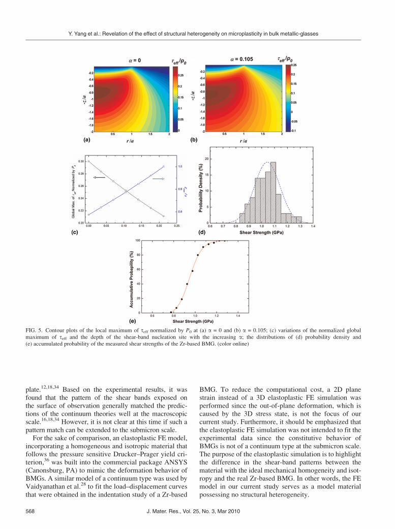
plate.12,18,34 Based on the experimental results, it wasfound that the pattern of the shear bands exposed onthe surface of observation generally matched the predic-tions of the continuum theories well at the macroscopicscale.16,18,34 However, it is not clear at this time if such apattern match can be extended to the submicron scale.
For the sake of comparison, an elastoplastic FE model,incorporating a homogeneous and isotropic material thatfollows the pressure sensitive Drucker–Prager yield cri-terion,36 was built into the commercial package ANSYS(Canonsburg, PA) to mimic the deformation behavior ofBMGs. A similar model of a continuum type was used byVaidyanathan et al.28 to fit the load–displacement curvesthat were obtained in the indentation study of a Zr-based
BMG. To reduce the computational cost, a 2D planestrain instead of a 3D elastoplastic FE simulation wasperformed since the out-of-plane deformation, which iscaused by the 3D stress state, is not the focus of ourcurrent study. Furthermore, it should be emphasized thatthe elastoplastic FE simulation was not intended to fit theexperimental data since the constitutive behavior ofBMGs is not of a continuum type at the submicron scale.The purpose of the elastoplastic simulation is to highlightthe difference in the shear-band patterns between thematerial with the ideal mechanical homogeneity and isot-ropy and the real Zr-based BMG. In other words, the FEmodel in our current study serves as a model materialpossessing no structural heterogeneity.
FIG. 5. Contour plots of the local maximum of teff normalized by P0 at (a) a = 0 and (b) a = 0.105; (c) variations of the normalized global
maximum of teff and the depth of the shear-band nucleation site with the increasing a; the distributions of (d) probability density and
(e) accumulated probability of the measured shear strengths of the Zr-based BMG. (color online)
Y. Yang et al.: Revelation of the effect of structural heterogeneity on microplasticity in bulk metallic-glasses
J. Mater. Res., Vol. 25, No. 3, Mar 2010568
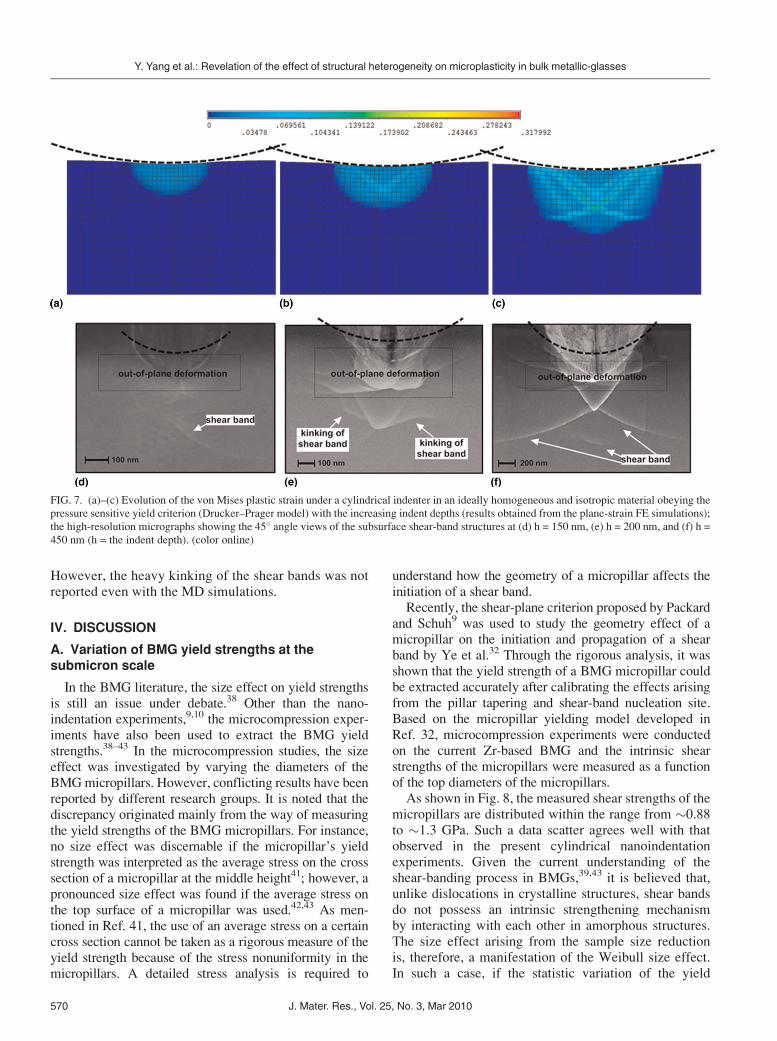
According to Su et al.,18 subsurface shear-band tra-jectories can be captured numerically with the vonMises plastic strains at the macroscopic scale. In ourFE simulations, the same approach was adopted andthe shear bands in the FE simulations were, thus,revealed using the von Mises plastic strains. As shownin Figs. 6(a)–6(c), the plastic strains are initially distrib-uted in a half-circular region underneath the indenter[Fig. 6(a)]; as the indentation depth increases, the plasticstrains are concentrated into two narrow bands in theradial directions [Fig. 6(b)], reminiscent of the forma-tion of a V-shaped shear-band pair as observed in themacroscopic wedge indentation experiments.16,18,34
With the further increase in the indentation depth, theshear bands cross each other at the axis of symmetry anda new V-shaped shear-band pair appears above thecrossing shear bands [Fig. 6(c)].
In contrast, only a single shear band in the radial direc-tion was observed in the cylindrical nanoindentation exper-iment at h = 150 nm [Fig. 6(d)], which corresponded to asingle load drop on the corresponding load–displacementcurve. As the indentation depth was increased to 200 and450 nm, the V-shaped shear-band pairs and crossing shearbands were observed underneath the indenter, respectively,which indicates that the experimental observations areindeed similar to what the FE simulations predict in the
general trend in some cases. However, one of the shearbands in Fig. 6(d) was heavily kinked, which differs fromthe FE simulation results. Interestingly, a 100-nm shear-band embryo was observed below the two crossing shearbands in Fig. 6(e), which indicates that shear banding stillprevails down to the length scale of �100 nm for thecurrent Zr-based BMG.
Kinking of shear bands was widely observed as thesubsurface radial shear bands extended to a few micro-meters in size. As shown in Figs. 7(a)–7(d), shear bandswere propagating along the tortuous trajectories. Thekinks along the shear bands had the spacing of a fewhundreds of nanometers and displayed the kink anglesranging from �18� to �40�. Despite the kinks, it can beseen that the overall trends of the radial shear-bandtrajectories roughly follow the predictions of the FEsimulations in their directions [Fig. 7(e)]. However,almost all the radial shear bands are unpaired, accumu-lating to one side of the indent. As compared with theFE simulation results for an ideally homogeneous andisotropic material, one-half of the shear bands seemmissing. It should be noted that such an asymmetricalshear-banding pattern was qualitatively captured by therecent molecular dynamics (MD) simulations,17,37 intowhich the structural variation in amorphous metals,such as the short range order (SRO), was incorporated.
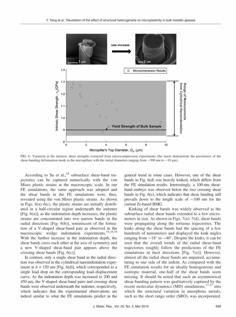
FIG. 6. Variation in the intrinsic shear strengths extracted from microcompression experiments (the insets demonstrate the persistence of the
shear-banding deformation mode in the micropillars with the initial diameters ranging from �500 nm to �10 mm).
Y. Yang et al.: Revelation of the effect of structural heterogeneity on microplasticity in bulk metallic-glasses
J. Mater. Res., Vol. 25, No. 3, Mar 2010 569
However, the heavy kinking of the shear bands was notreported even with the MD simulations.
IV. DISCUSSION
A. Variation of BMG yield strengths at thesubmicron scale
In the BMG literature, the size effect on yield strengthsis still an issue under debate.38 Other than the nano-indentation experiments,9,10 the microcompression exper-iments have also been used to extract the BMG yieldstrengths.38–43 In the microcompression studies, the sizeeffect was investigated by varying the diameters of theBMGmicropillars. However, conflicting results have beenreported by different research groups. It is noted that thediscrepancy originated mainly from the way of measuringthe yield strengths of the BMG micropillars. For instance,no size effect was discernable if the micropillar’s yieldstrength was interpreted as the average stress on the crosssection of a micropillar at the middle height41; however, apronounced size effect was found if the average stress onthe top surface of a micropillar was used.42,43 As men-tioned in Ref. 41, the use of an average stress on a certaincross section cannot be taken as a rigorous measure of theyield strength because of the stress nonuniformity in themicropillars. A detailed stress analysis is required to
understand how the geometry of a micropillar affects theinitiation of a shear band.Recently, the shear-plane criterion proposed by Packard
and Schuh9 was used to study the geometry effect of amicropillar on the initiation and propagation of a shearband by Ye et al.32 Through the rigorous analysis, it wasshown that the yield strength of a BMG micropillar couldbe extracted accurately after calibrating the effects arisingfrom the pillar tapering and shear-band nucleation site.Based on the micropillar yielding model developed inRef. 32, microcompression experiments were conductedon the current Zr-based BMG and the intrinsic shearstrengths of the micropillars were measured as a functionof the top diameters of the micropillars.As shown in Fig. 8, the measured shear strengths of the
micropillars are distributed within the range from �0.88to �1.3 GPa. Such a data scatter agrees well with thatobserved in the present cylindrical nanoindentationexperiments. Given the current understanding of theshear-banding process in BMGs,39,43 it is believed that,unlike dislocations in crystalline structures, shear bandsdo not possess an intrinsic strengthening mechanismby interacting with each other in amorphous structures.The size effect arising from the sample size reductionis, therefore, a manifestation of the Weibull size effect.In such a case, if the statistic variation of the yield
FIG. 7. (a)–(c) Evolution of the von Mises plastic strain under a cylindrical indenter in an ideally homogeneous and isotropic material obeying the
pressure sensitive yield criterion (Drucker–Prager model) with the increasing indent depths (results obtained from the plane-strain FE simulations);
the high-resolution micrographs showing the 45� angle views of the subsurface shear-band structures at (d) h = 150 nm, (e) h = 200 nm, and (f) h =
450 nm (h = the indent depth). (color online)
Y. Yang et al.: Revelation of the effect of structural heterogeneity on microplasticity in bulk metallic-glasses
J. Mater. Res., Vol. 25, No. 3, Mar 2010570
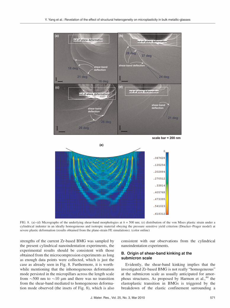
strengths of the current Zr-based BMG was sampled bythe present cylindrical nanoindentation experiments, theexperimental results should be consistent with thoseobtained from the microcompression experiments as longas enough data points were collected, which is just thecase as already seen in Fig. 8. Furthermore, it is worth-while mentioning that the inhomogeneous deformationmode persisted in the micropillars across the length scalefrom �500 nm to �10 mm and there was no transitionfrom the shear-band mediated to homogeneous deforma-tion mode observed (the insets of Fig. 8), which is also
consistent with our observations from the cylindricalnanoindentation experiments.
B. Origin of shear-band kinking at thesubmicron scale
Evidently, the shear-band kinking implies that theinvestigated Zr-based BMG is not really “homogeneous”at the submicron scale as usually anticipated for amor-phous structures. As proposed by Harmon et al.,44 theelastoplastic transition in BMGs is triggered by thebreakdown of the elastic confinement surrounding a
FIG. 8. (a)–(d) Micrographs of the underlying shear-band morphologies at h = 500 nm; (e) distribution of the von Mises plastic strain under a
cylindrical indenter in an ideally homogeneous and isotropic material obeying the pressure sensitive yield criterion (Drucker–Prager model) at
severe plastic deformation (results obtained from the plane-strain FE simulations). (color online)
Y. Yang et al.: Revelation of the effect of structural heterogeneity on microplasticity in bulk metallic-glasses
J. Mater. Res., Vol. 25, No. 3, Mar 2010 571
STZ. The percolation of the shear transformation eventsoccurring on the individual STZs then leads to the for-mation of a shear band. Based on the STZ model, onepossible explanation for the kinked shear band can be
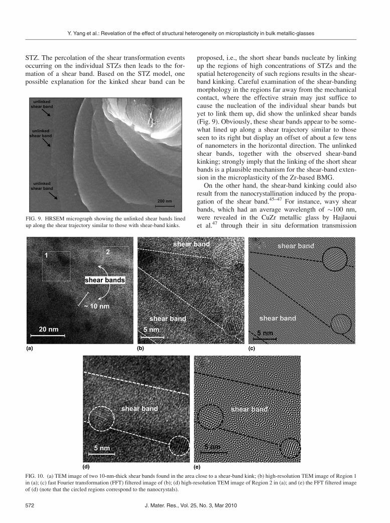
proposed, i.e., the short shear bands nucleate by linkingup the regions of high concentrations of STZs and thespatial heterogeneity of such regions results in the shear-band kinking. Careful examination of the shear-bandingmorphology in the regions far away from the mechanicalcontact, where the effective strain may just suffice tocause the nucleation of the individual shear bands butyet to link them up, did show the unlinked shear bands(Fig. 9). Obviously, these shear bands appear to be some-what lined up along a shear trajectory similar to thoseseen to its right but display an offset of about a few tensof nanometers in the horizontal direction. The unlinkedshear bands, together with the observed shear-bandkinking; strongly imply that the linking of the short shearbands is a plausible mechanism for the shear-band exten-sion in the microplasticity of the Zr-based BMG.On the other hand, the shear-band kinking could also
result from the nanocrystallination induced by the propa-gation of the shear band.45–47 For instance, wavy shearbands, which had an average wavelength of �100 nm,were revealed in the CuZr metallic glass by Hajlaouiet al.47 through their in situ deformation transmission
FIG. 9. HRSEM micrograph showing the unlinked shear bands lined
up along the shear trajectory similar to those with shear-band kinks.
FIG. 10. (a) TEM image of two 10-nm-thick shear bands found in the area close to a shear-band kink; (b) high-resolution TEM image of Region 1
in (a); (c) fast Fourier transformation (FFT) filtered image of (b); (d) high-resolution TEM image of Region 2 in (a); and (e) the FFT filtered image
of (d) (note that the circled regions correspond to the nanocrystals).
Y. Yang et al.: Revelation of the effect of structural heterogeneity on microplasticity in bulk metallic-glasses
J. Mater. Res., Vol. 25, No. 3, Mar 2010572
electron microscopy (TEM) analysis. Within these wavyshear bands, nanocrystals were observed growing togetherwith a tortuous shear crack. To ascertain the origin ofthe shear-band kinking observed in the cylindricalnanoindentation experiments, multiple TEM thin foilswere cut from the microlamella samples using FIB. Priorto the TEM examination, the TEM thin foils were thinneddown to a thickness of less than �50 nm for the revelationof the shear bands at the atomistic scale. As shown inFig. 10(a), two 10-nm-thick shear bands were observedon one of the TEM thin foils. Along these shear bands, afew nanocrystals, which had an average size of �5 nm,were found residing along the shear-band boundaries[Figs. 10(b)–10(e)]. It should be mentioned that the shear-band boundaries were sketched with the dashed linesin Figs. 10(b)–10(e) based on the contrast shown in thelow-resolution TEM image of the shear bands [Fig. 10(a)].
Despite the nanocrystallization seen along the shearbands, the shear-band profiles still remain as straightlocally. It is noted that the reported shear-band wavinessmainly occurred on the shear bands already expandedfrom a thickness of �10 to �100 nm. Since the shear-band thickening came along with the nanocrystal growthand shear-band cracking,47 the alteration of the shear-band profile caused by the nanocrystallization is likelyto occur in the severely deformed BMGs, whose status isalmost close to the final stage of failure. For the currentBMG microlamellae, the observed shear-band kinking isunlikely to be caused by the 5-nm sized nanocrystals. Inthe meantime, it is worthwhile mentioning that the nucle-ation of nanocrystals was confined to the shear bands asobserved in the TEM thin foil, which means that theobserved nanocrystallization was induced by the shear-banding process rather than by the ion-beam bombard-ment during the TEM sample preparation process.48
According to Shimitz et al.,49,50 the stress singularityahead of the shear-band tip scales with
ffiffiffiffiffiffiffil=w
p, where l
and w denote, respectively, the shear-band length andwidth. Therefore, for long shear bands, such as thoseobserved in the mm-sized specimens, the stress singularityat the shear-band tip is sufficient to break through anyobstacles ahead of the shear band. In such a case, the sheartrajectories are determined by the indentation stress fieldand the kinking of shear bands is, thus, smeared out by theoverall smoothness of the shear trajectories. In contrast,the microscale shear trajectories are more structurally sen-sitive and affected by the stress state as well as the struc-tural heterogeneity existing in amorphous structures.
V. CONCLUSIONS
In summary, a FIB-based nanoindentation method isused in this article to study the plastic deformation mech-anism in BMGs. Using the current method, the intrinsicshear strength of the Zr-based BMG was estimated,
which clearly showed a size effect on the BMG yieldstrengths and was consistent with the microcompressionresults. At the submicron/micrometer scale, it was foundthat kinking of shear bands became ubiquitous asopposed to the smooth shear trajectories observed at themacroscopic scale. Such a shear-band kinking phenome-non provides important experimental evidence to dem-onstrate the impact of structural heterogeneity on theplastic deformation in BMGs at the early stage.
ACKNOWLEDGMENTS
J.C. Ye and Y. Yang acknowledge the financial supportprovided by the Hong Kong Polytechnic University fornewly recruited staff (Project code: 1-ZV4J). J. Lu ac-knowledges the financial support from General ResearchFund (GRF), the Hong Kong Government, with the GrantNo. PolyU 5203/08E. P.K. Liaw is grateful to the sup-port of the National Science Foundation, InternationalMaterials Institutes (IMI) Program (DMR-0231320) withDr. C. Huber and Dr. D. Finotello as the Program Direc-tor, and thankful to Prof. Yokoyama for the provision ofthe testing material.
REFERENCES
1. K. Klement, R.H. Willens, and P. Duwez: Non-crystalline struc-
ture in solidified gold-silicon alloys. Nature 187, 869 (1960).
2. A.L. Greer: Metallic glasses. Science 267, 1947 (1995).
3. M.F. Ashby and A.L. Greer: Metallic glasses as structural mate-
rials. Scr. Mater. 54, 321 (2006).
4. M. Telford: The case for bulk metallic glass. Mater. Today 7, 36(2004).
5. A.S. Argon: Plastic deformation in metallic glasses. Acta Metall.27, 47 (1979).
6. W.L. Johnson and K. Samwer: A universal criterion for plastic
yielding of metallic glasses with a (T/Tg)2/3 temperature
depedence. Phys. Rev. Lett. 95, 195501 (2005).
7. J.C. Ye, J. Lu, Y. Yang, and P.K. Liaw: Study of the intrinsic
ductile to brittle transition mechanism of metallic glasses. ActaMater. 57, 6037 (2009).
8. C.A. Schuh, T.C. Hufnagel, and U. Ramamurty: Mechanical be-
havior of amorphous alloys. Acta Mater. 55, 4067 (2007).
9. C.E. Packard and C. Schuh: Initiation of shear bands near a stress
concentration in metallic glass. Acta Mater. 55, 5348 (2007).
10. H. Bei, Z.P. Lu, and E.P. George: Theoretical strength and the onset
of plasticity in bulk metallic glasses investigated by nanoindentation
with a spherical indenter. Phys. Rev. Lett. 93(12), 125504 (2004).11. C.A. Schuh, A.C. Lund, and T.G. Nieh: New regime of homoge-
neous flow in the deformation map of metallic glasses: Elevated
temperature nanoindentation experiments and mechanistic model-
ing. Acta Mater. 52, 5879 (2004).
12. A. Antoniou, A.F. Bastawros, C.C.H. Lo, and S.B. Biner: Defor-
mation behavior of a zirconium based metallic glass during cylin-
drical indentation: In situ observations. Mater. Sci. Eng., A 394,96 (2005).
13. M.J. Kramer, D.J. Sordelet, A.F. Bastarows, and X. Tan: Absence
of crystallization during cylindrical indentation of a Zr-based
metallic glass. J. Non-Cryst. Solids 351, 2159 (2005).
14. U. Ramamurty, S. Jana, Y. Kawamura, and K. Chattopadhyay:
Hardness and plastic deformation in a bulk metallic glass. ActaMater. 53, 705 (2005).
Y. Yang et al.: Revelation of the effect of structural heterogeneity on microplasticity in bulk metallic-glasses
J. Mater. Res., Vol. 25, No. 3, Mar 2010 573

15. H.W. Zhang, X.N. Jing, G. Subhash, L.J. Kecskes, and R.J. Dowding:
Spatiotemporally inhomogeneous plastic flow of a bulk-metallic
glass. Investigation of shear band evolution in amorphous alloys
beneath a Vickers indentation. Acta Mater. 53(14), 3849 (2005).16. A. Antoniou, A. Bastawros, and B. Biner: Experimental observa-
tions of deformation behavior of bulk metallic glasses during wedge-
like cyclindrical indentation. J. Mater. Res. 22(2), 514 (2007).17. Y. Shi and M.L. Falk: Does metallic glass have a backbone? The
role of percolating short range order in strength and failure. Scr.Mater. 54, 381 (2006).
18. C. Su and L. Anand: Plane strain indentation of a Zr-based metal-
lic glass: Experiments and numerical simulation. Acta Mater.54(1), 179 (2006).
19. N. Li, L. Liu, Q. Chen, J. Pan, and K.C. Chan: The effect of free
volume on the deformation behaviour of a Zr-based metallic glass
under nanoindentation. J. Phys. D: Appl. Phys. 40, 6055 (2007).
20. F. Yang, K. Geng, P.K. Liaw, G. Fan, and H. Choo: Deformation
in a Zr57Ti5Cu20Ni8Al10 bulk metallic glass during nanoindenta-
tion. Acta Mater. 55, 321 (2007).
21. W. Jiang, G.J. Fan, F. Liu, G.Y. Wang, H. Choo, and P.K. Liaw:
Spatiotemporally inhomogeneous plastic flow of a bulk-metallic
glass. Int. J. Plast. 24(1), 1 (2008).
22. Y.C. Lu, S.N.V.R.K. Kurapati, and F. Yang: Finite element anal-
ysis of cylindrical indentation for determining plastic properties of
materials in small volumes. J. Phys. D: Appl. Phys. 41(11),115415 (2008).
23. D. Pan, A. Inoue, T. Sakurai, and M.W. Chen: Experimental charac-
terization of shear transformation zones for plastic flow of bulk
metallic glasses. Proc. Nat. Acad. Sci. U.S.A. 105(39), 14769 (2008).24. W. Jiang, G.J. Fan, F. Liu, G.Y. Wang, H. Choo, and P. Liaw:
Spatiotemporally inhomogeneous plastic flow of a bulk-metallic
glass. Int. J. Plast. 24, 1 (2008).
25. H. Zhang, S. Maiti, and G. Subhash: Evolution of shear bands in
bulk metallic glasses under dynamic loading. J. Mech. Phys.Solids 56(6), 2171 (2008).
26. M. Uchic, D.M. Dimiduk, J.N. Florando, and W.D. Nix: Sample
dimensions influence strength and crystal plasticity. Science 305,986 (2004).
27. Y. Yang, J.C. Ye, J. Lu, F.X. Liu, and P.K. Liaw: Effects of
specimen geometry and base material on the mechanical behavior
of focused-ion-beam-fabricated metallic-glass micropillars. ActaMater. 57, 1613 (2009).
28. R. Vaidyanathan, M. Dao, G. Ravichandran, and S. Suresh: Study
of mechanical deformation in bulk metallic glass through instru-
mented indentation. Acta Mater. 49, 3781 (2001).
29. C.A. Schuh and A.C. Lund: Atomistic basis for the plastic yield
criterion of metallic glass. Nat. Mater. 2, 449 (2003).
30. M.N.M. Patnaik, R. Narasimhan, and U. Ramamurty: Spherical
indentation response of metallic glasses. Acta Mater. 52(11), 3335(2004).
31. A. Dubach, K.E. Prasad, R. Raghavan, J.F. Loffler, J. Michler,
and U. Ramamurty: Free-volume dependent pressure sensitivity
of Zr-based bulk metallic glass. J. Mater. Res. 24(8), 2697
(2009).
32. J.C. Ye, J. Lu, Y. Yang, and P.K. Liaw: Extraction of bulk
metallic-glass yield strengths using tapered micropillars in micro-
compression experiments. Intermetallics 18, 385 (2010).
33. A.C. Fischer Cripps: Introduction to Contact Mechanics(Springer, New York, 2000).
34. A. Antoniou, A. Bastarows, and B. Biner: Experimental observa-
tions of deformation behavior of bulk metallic glasses during
wedge-like cylindrical indentation. J. Mater. Res. 22(2), 514 (2007).35. F. Yang, D. Li, M.L. Yang, R. Li, W. Jiang, G. Wang, T. Zhang,
and P.K. Liaw: Localized deformation of a Cu46.25Zr45.25Al7.5Er1bulk metallic glass. J. Phys. D: Appl. Phys. 42, 065401 (2009).
36. M. Martin, L. Kecskes, and N.N. Thadhani: Dynamic compres-
sion of a zirconium-based bulk metallic glass confined by a stain-
less steel sleeve. Scr. Mater. 59, 688 (2008).
37. Y. Shi and M.L. Falk: Stress-induced structural transformation
and shear banding during simulated nanoindentation of a metallic
glass. Acta Mater. 55, 4317 (2007).
38. B.E. Schuster, Q. Wei, T.C. Hufnagel, and K.T. Ramesh: Size-
independent strength and deformation mode in compression of a
Pd-based metallic glass. Acta Mater. 56, 5091 (2008).
39. B.E. Schuster, Q. Wei, M.H. Ervin, S.O. Hruszkewycz,
M.K. Miller, T.C. Hufnagel, and K.T. Ramesh: Bulk and micro-
scale compressive properties of a Pd-based metallic glass. Scr.Mater. 57, 517 (2007).
40. A. Dubach, R. Raghavan, J.F. Loffler, J. Michler, and
U. Ramamurty: Micropillar compression studies on a bulk metal-
lic glass in different structural states. Scr. Mater. 60, 567 (2009).
41. C.A. Volkert, A. Donohue, and F. Spaepen: Effect of sample size on
deformation in amorphous metals. J. Appl. Phys. 103, 083539 (2008).42. Y.H. Lai, C.J. Lee, Y.T. Cheng, H.S. Chou, H.M. Chen, X.H. Du,
C.I. Chang, J.C. Huang, S.R. Jian, J.S.C. Jang, and T.G. Nieh:
Bulk and microscale compressive behavior of a Zr-based metallic
glass. Scr. Mater. 58, 890 (2008).
43. C.J. Lee, J.C. Huang, and T.G. Nieh: Sample size effect and
microcompression of Mg65Cu25Gd10 metallic glass. Appl. Phys.Lett. 91, 161913 (2007).
44. J.S. Harmon, D.M. Demetriou, W.L. Johnson, and K. Samwer:
Anelastic to plastic transition in metallic glass-forming liquids.
Phys. Rev. Lett. 99, 135502 (2007).
45. J-J. Kim, Y. Choi, S. Suresh, and A.S. Argon: Nanocrystallization
during nanoindentation of a bulk amorphous metal alloy at room
temperature. Science 295, 654 (2002).
46. K. Wang, T. Fujita, Y.Q. Zeng, N. Nishiyama, A. Inoue, and
M.W. Chen: Micromechanisms of serrated flow in a Ni50Pd30P20bulk metallic glass with a large compression plasticity. ActaMater. 56, 2834 (2008).
47. K. Hajlaoui, A.R. Yavari, B. Doisneau, A. LeMoulec, W.J. Botta,
G. Vaughan, A.L. Greer, A. Inoue, W. Zhang, and A. Kvick:
Shear delocalization and crack blunting of a metallic glass
containing nanoparticles: In situ deformation in TEM analysis.
Scr. Mater. 54, 1829 (2006).
48. B.B. Sun, Y.B. Wang, J. Wen, H. Yang, M.L. Sui, J.Q. Wang, and
E. Ma: Artifacts induced in metallic glasses during TEM sample
preparation. Scr. Mater. 53, 805 (2005).
49. F. Shimizu, S. Ogata, and J. Li: Theory of shear banding in
metallic glasses and molecular dynamics calculations. Mater.Trans., JIM 48(11), 2923 (2007).
50. F. Shimizu, S. Ogata, and J. Li: Yield point of metallic glass. ActaMater. 54, 4293 (2006).
APPENDIX
Under the plane strain condition, the three Hertizianstress components sr, sz, and trz, as defined in Fig. 4(b),can be derived as33
sr ¼ �P0
am 1þ z2 þ n2
m2 þ n2
� �� 2z
� ; ðA1Þ
sz ¼ P0
am 1� z2 þ n2
m2 þ n2
� �; ðA2Þ
trz ¼ �P0
an
m2 � z2
m2 þ n2
� �; ðA3Þ
Y. Yang et al.: Revelation of the effect of structural heterogeneity on microplasticity in bulk metallic-glasses
J. Mater. Res., Vol. 25, No. 3, Mar 2010574

in which
m2 ¼ 1
2½fða2 � r2 þ z2Þ2 þ 4r2z2g1=2 þ ða2 � r2 þ z2Þ� ;
ðA4Þ
n2 ¼ 1
2½fða2 � r2 þ z2Þ2 þ 4r2z2g1=2 � ða2 � r2 þ z2Þ� ;
ðA5Þ
P0 ¼ PE�
pR
� �1=2
; ðA6Þ
where a is the contact diameter; r is the radial dis-tance to the axis of symmetry; z is the distance to thesample surface; R is the indenter tip radius; P is theindentation load and E* is the reduced modulus anddefined as
1
E� ¼1� v2
Eþ 1� v2i
Ei: ðA7Þ
In Eq. (A7), E and Ei denote, respectively, theYoung’s moduli of the BMG and the diamond indenter;whereas n and ni denote the Poisson’s ratios of the BMGand the diamond indenter, respectively.
Y. Yang et al.: Revelation of the effect of structural heterogeneity on microplasticity in bulk metallic-glasses
J. Mater. Res., Vol. 25, No. 3, Mar 2010 575