Embed Size (px)
Citation preview
REVERSE ENGINEERING OF MOBILE PHONE CASING
AND ANALYSIS OF WELD-LINE DEFECT
TOH BAN SHENG
A thesis submitted in partial fulfillment of the requirement
for the award of the degree of
Bachelor of Mechanical Engineering with Manufacturing Engineering
Faculty of Mechanical Engineering
Universiti Malaysia Pahang
NOVEMBER 2009
SUPERVISOR’S DECLARATION
I hereby declare that I have checked this project and in my opinion, this project is
adequate in terms of scope and quality for the award of the degree of Bachelor of
Mechanical Engineering with Manufacturing Engineering.
Signature :…………………………….
Name of Supervisor : En. Asnul Hadi Bin Ahmad
Position : Lecturer
Date :…………………..…………

STUDENT’S DECLARATION
I hereby declare that the work in this project is my own except for quotations and
summaries which have been duly acknowledged. The project has not been accepted for
any degree and is not concurrently submitted for award of other degree.
Signature : …………………..…………
Name : Toh Ban Sheng
ID Number : ME06044
Date : …………………..…………

Dedicated to my beloved parents
and
siblings
ACKNOWLEDGEMENTS
The author would like to express the heartiest gratitude to author’s supervisor
Encik Asnul Hadi Bin Ahmad for his patient guidance and continuous encouragement
which significantly helped me to finish this project successfully. The author appreciates
his consistent support throughout the progress of the project and his tolerance to my
naïve mistakes. Endless thank-yous go to all the staffs of Faculty of Mechanical
Engineering and fellow friends in UMP who have always been rendering the author
assistance and make his stay in UMP pleasant and unforgettable. The author
acknowledges his sincere indebtedness and gratitude to his parents for their sacrifices
and encouragement to give the author such a precious to continue his higher education
in UMP. Again, special thanks to all who had been such crucial roles for the successful
completion of this study.
ABSTRACT
In recent decades, reverse engineering (RE) has gradually become important when it comes to the situation that a component must be reproduced but its original engineering data are no longer or not accessible. Sophisticated technologies are introduced for the purpose of reverse engineering. The state-of-the-art technology in latest days is the use of 3D laser scanning with aid of reverse-engineering software to create the 3D geometry model of the existing component. The most appropriate way to duplicate the component is by plastic injection moulding. However, defect such as weld lines always occur during injection moulding process which makes the component aesthetically and structurally unacceptable. Therefore, injection moulding simulation on the component is necessary to investigate the variables that affect the formation of weld lines. Simulations are repetitively done to determine the most optimal variables that remove or reduce weld lines to minimum before the component is ready for reproduction.
ABSTRAK
‘Reverse engineering’ (R.E) kian memainkan peranan penting dalam zaman sekarang kerana selalu berlakunya bahawa sesuatu produk yang telah wujud perlu dihasilkan semula, tetapi tanpa data asal rekabentuknya. Beberapa teknologi yang canggih telah diperkenalkan untuk tujuan RE. Salah satu teknologi yang terkini ialah cara ‘3D laser scanning’ yang digunakan untuk menghasilkan model geometri 3D produk yang bakal dihasilkan semula. Model geometri 3D amat penting untuk tujuan simulasi pengacuan suntikan. Melalui simulasi tersebut, kecacatan yang terhasil seperti ‘weld lines’ dapat diperlihatkan. Kewujudan ‘weld lines’ sedemikian bukan sahaja menjadikan permukaan produk menjadi kurang menarik, tetapi juga menyebabkan ketahanan dan kelasakan pada bahagian ‘weld lines’. Maka, simulasi pengacuan suntikan adalah sangat penting untuk menentukan factor-faktor yang mengakibatkan pembentukan kecacatan tersebut. Simulasi dijalankan berulang-ulang kali sehingga pembentukan ‘weld lines’ telah dihilangkan atau dikurangkan kepada jumlah yang paling minimum.
TABLE OF CONTENTS
CHAPTER TITLE PAGE
TITLE PAGE i
SUPERVISOR DECLARATION ii
STUDENT DECLARATION iii
DEDICATION iv
ACKNOWLEDGEMENT v
ABSTRACT vi
ABSTRAK vii
TABLE OF CONTENTS viii
LIST OF TABLES xi
LIST OF FIGURES xii
LIST OF SYMBOLS xv
LIST OF ABBREVIATIONS xvi
1 INTRODUCTION 1
1.1 Introduction 1
1.2 Problem Statement 2
1.3 Objectives 2
1.4 Scope of Study 3
2 LITERATURE REVIEW 4
2.1 Reverse Engineering 4
2.1.1 Introduction 4
2.1.2 Application of Reverse Engineering 5
2.1.3 Importance of Reverse Engineering 7
2.2 Reverse Engineering – The Generic Process 7
2.2.1 Date Digitisation 8
2.2.2 Coordinate Reconstruction 9
2.2.3 Data Point Manipulation 10
2.2.4 Surface Approximation 10
2.3 Injection Moulding 10
2.3.1 Processing Conditions 11
2.3.1.1 Melt Temperature 11
2.3.1.2 Injection Pressure 12
2.3.1.3 Injection Speed 12
2.3.1.4 Packing Time 12
2.3.1.5 Cooling Time 13
2.4 Product Design 13
2.4.1 Uniform Wall Thickness 13
2.4.2 Balance Geometrical Configuration 14
2.4.3 Smooth Internal Sharp Corners 14
2.4.4 Draft Walls 14
2.4.5 Feather Edges 14
2.4.6 Proportional Boss Geometries 15
2.4.7 Gate Type and Location 15
2.4.8 Runner Sizing 15
2.5 Simulation of Injection Moulding 16
2.5.1 Finite Elements Used by Simulation Software 16
2.5.2 Mesh requirements and Weld-Line Prediction 17
2.6 Weld Lines 17
3 METHODOLOGY 20
3.1 Introduction 20
3.2 Three-Dimensional Laser Scanning 22
3.3 3D Geometry CAD Model 23
3.4 Selection of Material 23
3.5 Selection of Simulation Software 24
3.6 Simulation of Injection Moulding 24
4 RESULTS AND DISCUSSIONS 26
4.1 Introduction 26
4.2 Computer-Aided Design (CAD) Model 26
4.3 The Advanced Gate Locator Algorithm 27
4.4 Factors of Weld-Line Formation 28

4.4.1 Number and Location of Injection Gates 29
4.4.2 Wall Thickness of Mobile Phone Casing 30
4.4.3 Runner Sizing 32
4.4.4 Injection Pressure 33
4.4.5 Melt Temperature 34
4.5 Summary of Simulation of Fewest Weld Lines 36
4.6 Discussions 36
4.6.1 Method of Reverse Engineering 36
4.6.2 Effect of Number of Gates on Weld-Line Formation
37
4.6.3 Effect of Gate Location on Weld-Line Formation
37
4.6.4 Effect of Wall Thickness on Weld-Line Formation
37
4.6.5 Effect of Runner Sizing on Weld-Line Formation
38
4.6.6 Effect of Injection Pressure and Melt Temperature on Weld-Line Formation
39
5 CONCLUSION AND FUTURE WORKS 41
5.1 Conclusion 41
5.2 Future Works 41
REFERENCES 42
APPENDICES 44
LIST OF TABLES
TABLE NO. TITLE PAGE
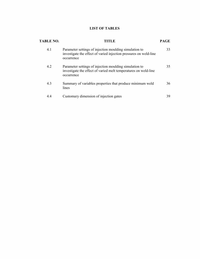
4.1 Parameter settings of injection moulding simulation to investigate the effect of varied injection pressures on weld-line occurrence
33
4.2 Parameter settings of injection moulding simulation to investigate the effect of varied melt temperatures on weld-line occurrence
35
4.3 Summary of variables properties that produce minimum weld lines
36
4.4 Customary dimension of injection gates 39
LIST OF FIGURES
FIGURE
NO.TITLE PAGE
2.1 Difference between reverse engineering and traditional engineering 5
2.2 Four-engine propeller-driven heavy bomber “The Boeing B-29 Superfortress” flown by the United States Military inWorld War II 6
2.3 Reverse-engineered copy of U.S.-made “The Boeing B-29Superfortress” by the Soviet Union 6
2.4 Prosthetic finger duplicated by reverse engineering 7
2.5 Block diagram of reverse-engineering generic process based on the scanning strategy 8
2.6 Contact scanner with touch probe and non-contact scanner with laser beam 9
2.7 CAD model of a mobile phone casing generated by 3D scanning strategy 10
2.8 The reciprocating-screw injection-moulding machine 11
2.9 Element types 17
2.10 Formation of weld lines when two melt fronts meet 18
3.1 Flow chart of methodology 21
3.2 Top view (middle) and bottom view (right) of upper part of mobile phone casing of Nokia 9500 22
3.3 Three-dimensional laser scanner 23
3.4 Testing on injection mould design by simulating mould flow process 25
4.1 CAD model of Nokia 9500 mobile phone casing (isometric view) 26
4.2 Top view (a) and bottom view (b) CAD model of Nokia 9500 mobile phone casing 27
4.3 Prohibited surface for injection gate location is highlighted in red colour 28
4.4 Constant variables (parameter settings of injection moulding simulations) 28
4.5 Weld lines produced by 3 injection gates 29
4.6 Weld lines produced by two injection gates at location A 29
4.7 Weld lines produced by one injection gate at location A 30
4.8 CAD Models of mobile phone casings at different wall thickness 31
4.9 Weld lines produced at wall thickness of 1.5mm 31
4.10 Weld lines produced by runner diameter of 2.042mm 33
4.11 Weld lines produced at the injection pressure of 180 MPa 34
4.12 Weld lines produced at the melt temperature of 210°C 35
4.13 Increasing the melt temperature and injection pressure will result in more molecular diffusion and entanglement taking place at weld interface
40
A(1) Weld lines produced by two injection gates at location B 44
A(2) Weld lines produced by two injection gates at location C 44
B(1) Weld lines produced by one injection gate at location B 45
B(2) Weld lines produced by one injection gate at location C 45
B(3) Weld lines produced by one injection gate at location D 46
C(1) Weld lines produced at wall thickness of 1.8mm 47
C(2) Weld lines produced at wall thickness of 2.0mm 47
C(3) Weld lines produced at wall thickness of 2.5mm 48
C(4) Weld lines produced at wall thickness of 2.8mm 48
C(5) Weld lines produced at wall thickness of 3.0mm 48
D(1) Weld lines produced by runner diameter of 2.542mm 49
D(2) Weld lines produced by runner diameter of 3.042mm 49
D(3) Weld lines produced by runner diameter of 3.542mm 50
E(1) Weld lines produced at the injection pressure of 200 MPa 51
E(2) Weld lines produced at the injection pressure of 220 MPa 51
E(3) Weld lines produced at the injection pressure of 240 MPa 52
F(1) Weld lines produced at the melt temperature of 230°C 53
F(2) Weld lines produced at the melt temperature of 250°C 53
F(3) Weld lines produced at the melt temperature of 270°C 54
LIST OF SYMBOLS
D Diameter of runner
Ø Diameter of runner
W Weight of mobile phone casing
L Length of runner
°C Degree Celsius (Temperature)
MPa Mega Pascal (Pressure)
g Gram (Mass)
LIST OF ABBREVIATIONS
ABS Acrylonitrile butadiene styrene
AMA 2010 Autodesk® Moldflow® Adviser 2010
CAD Computer-aided design
CAM Computer-aided Manufacturing
CCD Charge coupled device
CMM Coordinate measurement machine
LED Light-emitting diode
RE Reverse engineering
NC Numerical control
3D Three dimensional
USSR Union of Soviet Socialist Republics

CHAPTER 1
INTRODUCTION
1.1 Introduction
Engineering is the process of designing, manufacturing, assembling, and
maintaining products or systems. However, there are two types of engineering, forward
engineering and reverse engineering. Reverse engineering differs from forward
engineering in such a way that the basic concept of duplicating an existing part based on
an original or physical model without the use of an engineering drawings or
documentations. Thus, reverse engineering can be known as re-engineering an existing
product as well. In such an intensely competitive global market nowadays, product
enterprises are constantly seeking novel ways to shorten lead times for new product
developments that cater for all consumer expectations. Generally, product enterprise has
invested tremendously in computer-aided design and manufacturing (CADCAM) and a
wide range of new technologies that provide business benefits. Reverse engineering
(RE) is now considered as one of the state-of-the-art technologies that is advantageous
in significantly shortening the product development cycle. (Raja et al., 2008).
Reverse engineering of mobile phone casing involves disassembly of an existing
mobile phone casing to figure out how it was built and how does it work. The mobile
phone casing is undergoing a physical-to-digital process, in which its geometry
computer-aided design (CAD) model (digital) is created by scanning the existing object
(Lai et al., 1998). Three-dimensional scanners are employed to scan the part geometry
capturing information that describes all geometric features such as steps, slots, pockets
and holes. The fabricate of the mobile phone casing, injection moulding is the most
ideal way as it is a versatile process capable of producing complex shapes with good
dimensional accuracy. During the injection moulding, structural defects such as weld

2
lines can occur. These defects can develop in manufacturing processes depending on
factors such as materials, part design, and processing techniques. These factors are
crucial considerations to be taken in terms of defect elimination.
In recent decades, much progress has been made in the analysis of material flow
in injection moulding, Modelling techniques and simulation software has been
developed for studying optimum gating systems, mould filling, mould cooling, and part
distortion. Software programs expedite the design process for moulding parts with good
dimensions and characteristics. The programs take into account such significant factors
as injection pressure and temperature (Schmid et al., 2006). The reverse engineering of
mobile phone casing project is completed with the simulation of a defect-free injection
moulding process.
1.2 Problem Statement
Reverse engineering has been rather common and essential especially when it
comes to a situation that the original product design documentation has been obsolete or
never existed, some bad features of a product need to be eliminated, analysing the good
and bad features of competitors’ products, exploring new avenues to improve product
performance and features and so forth (Raja et al., 2008). Defect such as weld lines
always occur during injection moulding which affect the appearance also has adverse
effects on the structural integrity of the products. Thus, this defect has to be removed.
1.3 Objectives
The objectives of “Reverse Engineering of Mobile Phone Casing and Analysis
of weld Line Defect” project are to:
i) Create a CAD model of mobile phone casing by using reverse-engineering hardware and software
ii) Investigate weld lines based on injection moulding simulation

3
1.4 Scope of Study
The scope of study for this project includes the disassembly of a mobile phone
casing and creation of its geometry CAD model by employing 3D laser scanner with the
aid of PolyWorks software which reconstructs the scanned data into a 3D geometry
CAD model. The CAD model is imported into Autodesk® Moldflow® Adviser 2010
software to simulate the material flowing process and to test the manufacturability of the
object. Factors of causing weld-line defect are analysed to find out ways such as
necessary alterations on the parameter settings in order to remove the weld-line defects.
CHAPTER 2
LITERATURE REVIEW
2.1 Reverse Engineering
2.1.1 Introduction
In common usage in industry, RE often involves taking something apart and
analyzing its workings in detail, usually with the intention to construct a new device or
program that does the same thing without actually copying anything from the original.
But it is important to realise that it is possible to reverse engineer almost any system,
even living systems or self-organizing systems that were not “engineered” in the first
place, such as a mechanical device, an electronic component, a software program, a
living cell or organism, or even a geologic structure. In this sense, reverse engineering
is essentially science, using the scientific method as well as measurement, analysis and
other tools to gain an understanding of the inner workings and overall function of a
system or structure. Thus, sciences such as biology and physics can be seen as reverse
engineering of living biological systems' and the physical world respectively (Vinesh et
al., 2008).
In the United States and many other countries, even if an artifact or process is
protected by trade secrets, reverse-engineering the artifact or process is often perfectly
legal as long as it is obtained legitimately. Patents, on the other hand, require a public
disclosure of an invention, and therefore patented items don't necessarily have to be
reverse engineered to be studied. One common motivation of reverse engineers is to
determine whether a competitor's product contains patent infringements or copyright
infringements.
5
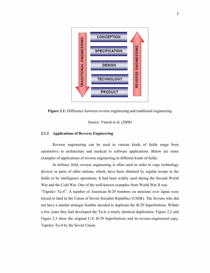
Figure 2.1: Difference between reverse engineering and traditional engineering
Source: Vinesh et al. (2008)
2.1.2 Applications of Reverse Engineering
Reverse engineering can be used in various kinds of fields range from
automotive to architecture and medical to software applications. Below are some
examples of applications of reverse engineering in different kinds of fields.
In military field, reverse engineering is often used in order to copy technology
devices or parts of other nations, which, have been obtained by regular troops in the
fields or by intelligence operations. It had been widely used during the Second World
War and the Cold War. One of the well-known examples from World War II was
“Tupolev Tu-4”. A number of American B-29 bombers on missions over Japan were
forced to land in the Union of Soviet Socialist Republics (USSR). The Soviets who did
not have a similar strategic bomber decided to duplicate the B-29 Superfortress. Within
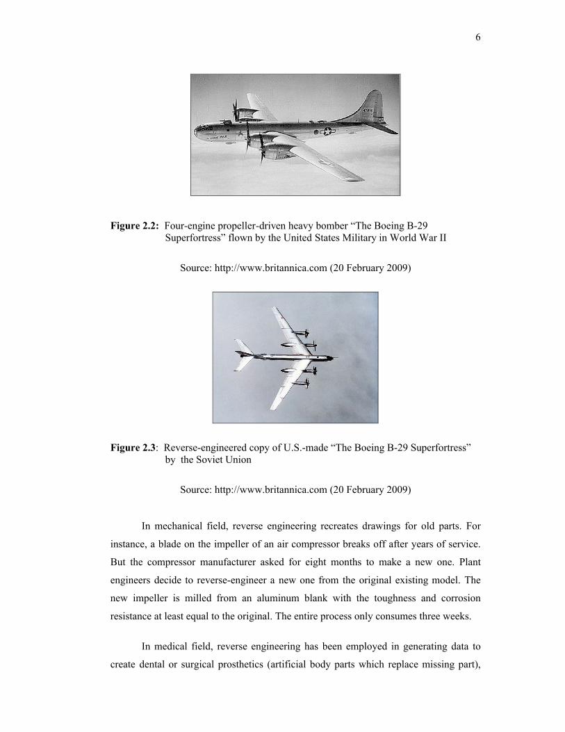
a few years they had developed the Tu-4, a nearly identical duplication. Figure 2.2 and
Figure 2.3 show the original U.S. B-29 Superfortress and its reverse-engineered copy,
Tupolev-Tu-4 by the Soviet Union.
6
Figure 2.2: Four-engine propeller-driven heavy bomber “The Boeing B-29 Superfortress” flown by the United States Military in World War II
Source: http://www.britannica.com (20 February 2009)
Figure 2.3: Reverse-engineered copy of U.S.-made “The Boeing B-29 Superfortress” by the Soviet Union
Source: http://www.britannica.com (20 February 2009)
In mechanical field, reverse engineering recreates drawings for old parts. For
instance, a blade on the impeller of an air compressor breaks off after years of service.
But the compressor manufacturer asked for eight months to make a new one. Plant
engineers decide to reverse-engineer a new one from the original existing model. The
new impeller is milled from an aluminum blank with the toughness and corrosion
resistance at least equal to the original. The entire process only consumes three weeks.
In medical field, reverse engineering has been employed in generating data to
create dental or surgical prosthetics (artificial body parts which replace missing part),
7
tissue engineered body parts, or for surgical planning. A virtually perfectly custom-fit
prosthetic can be duplicated to replace the missing part such as knee joint, femur bones
and teeth lost by injury (traumatic) or missing from birth (congenital) or to supplement
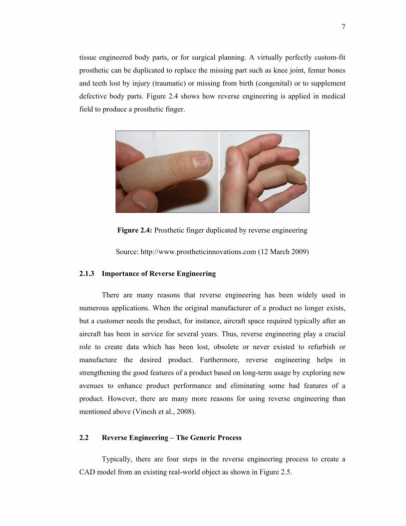
defective body parts. Figure 2.4 shows how reverse engineering is applied in medical
field to produce a prosthetic finger.
Figure 2.4: Prosthetic finger duplicated by reverse engineering
Source: http://www.prostheticinnovations.com (12 March 2009)
2.1.3 Importance of Reverse Engineering
There are many reasons that reverse engineering has been widely used in
numerous applications. When the original manufacturer of a product no longer exists,
but a customer needs the product, for instance, aircraft space required typically after an
aircraft has been in service for several years. Thus, reverse engineering play a crucial
role to create data which has been lost, obsolete or never existed to refurbish or
manufacture the desired product. Furthermore, reverse engineering helps in
strengthening the good features of a product based on long-term usage by exploring new
avenues to enhance product performance and eliminating some bad features of a
product. However, there are many more reasons for using reverse engineering than
mentioned above (Vinesh et al., 2008).
2.2 Reverse Engineering – The Generic Process
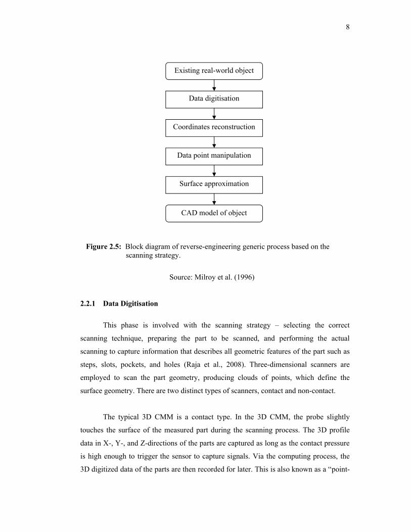
Typically, there are four steps in the reverse engineering process to create a
CAD model from an existing real-world object as shown in Figure 2.5.
8
Figure 2.5: Block diagram of reverse-engineering generic process based on the scanning strategy.
Source: Milroy et al. (1996)
2.2.1 Data Digitisation
This phase is involved with the scanning strategy – selecting the correct
scanning technique, preparing the part to be scanned, and performing the actual
scanning to capture information that describes all geometric features of the part such as
steps, slots, pockets, and holes (Raja et al., 2008). Three-dimensional scanners are
employed to scan the part geometry, producing clouds of points, which define the
surface geometry. There are two distinct types of scanners, contact and non-contact.
The typical 3D CMM is a contact type. In the 3D CMM, the probe slightly
touches the surface of the measured part during the scanning process. The 3D profile
data in X-, Y-, and Z-directions of the parts are captured as long as the contact pressure
is high enough to trigger the sensor to capture signals. Via the computing process, the
3D digitized data of the parts are then recorded for later. This is also known as a “point-
Existing real-world object
Data digitisation
Coordinates reconstruction
Data point manipulation
Surface approximation
CAD model of object