Embed Size (px)
Citation preview

Review 2: Illumination, Shading, Texturing and Anti-aliasing
Jian Huang, CS594, Spring 2002

Illumination Vs. Shading
Illumination (lighting) model: determine the color of a surface point by simulating some light attributes.
Shading model: applies the illumination models at a set of points and colors the whole image.

Local illumination
• Only consider the light, the observer position, and the object material properties

Basic Illumination Model
• Simple and fast method for calculating surface intensity at a given point
• Lighting calculating are based on:– The background lighting conditions– The light source specification: color, position– Optical properties of surfaces:
• Glossy OR matte• Opaque OR transparent (control refection and
absorption)
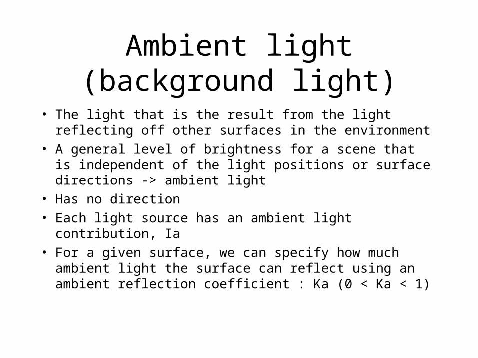
Ambient light (background light)
• The light that is the result from the light reflecting off other surfaces in the environment
• A general level of brightness for a scene that is independent of the light positions or surface directions -> ambient light
• Has no direction• Each light source has an ambient light contribution, Ia• For a given surface, we can specify how much
ambient light the surface can reflect using an ambient reflection coefficient : Ka (0 < Ka < 1)
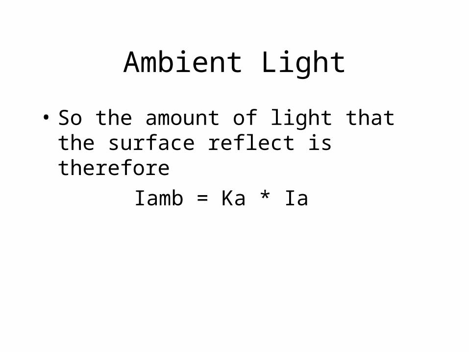
Ambient Light
• So the amount of light that the surface reflect is therefore
Iamb = Ka * Ia
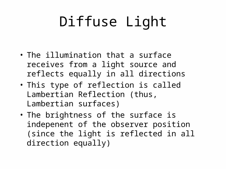
Diffuse Light
• The illumination that a surface receives from a light source and reflects equally in all directions
• This type of reflection is called Lambertian Reflection (thus, Lambertian surfaces)
• The brightness of the surface is indepenent of the observer position (since the light is reflected in all direction equally)
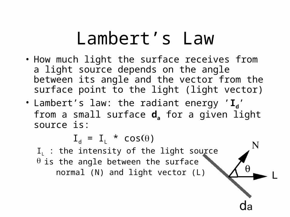
Lambert’s Law• How much light the surface receives from a
light source depends on the angle between its angle and the vector from the surface point to the light (light vector)
• Lambert’s law: the radiant energy ’Id’ from a small surface da for a given light source is:
Id = IL * cos)IL : the intensity of the light source is the angle between the surface normal (N) and light vector (L)
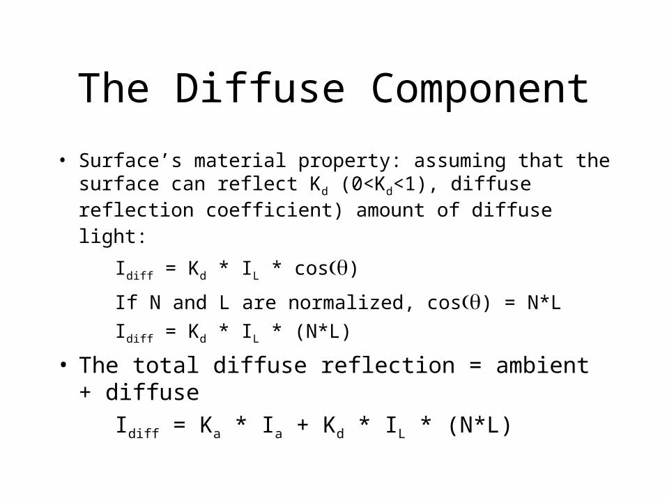
The Diffuse Component
• Surface’s material property: assuming that the surface can reflect Kd (0<Kd<1), diffuse reflection
coefficient) amount of diffuse light:
Idiff = Kd * IL * cos)
If N and L are normalized, cos) = N*L
Idiff = Kd * IL * (N*L)
• The total diffuse reflection = ambient + diffuse
Idiff = Ka * Ia + Kd * IL * (N*L)

Examples
Sphere diffusely lighted from various angles !

Specular Light
These are the bright spots on objects (such as polished metal, apple ...)
Light reflected from the surface unequally to all directions.
The result of near total reflection of the incident light in a concentrated region around the specular reflection angle

Phong’s Model for Specular
• How much reflection light you can see depends on where you are

Phong Illumination Curves
Specular exponents are much larger than 1;
Values of 100 are not uncommon.
n : glossiness, rate of falloff

Specular Highlights
• Shiny surfaces change appearance when viewpoint is changed• Specularities are caused by microscopically smooth surfaces.• A mirror is a perfect specular reflector
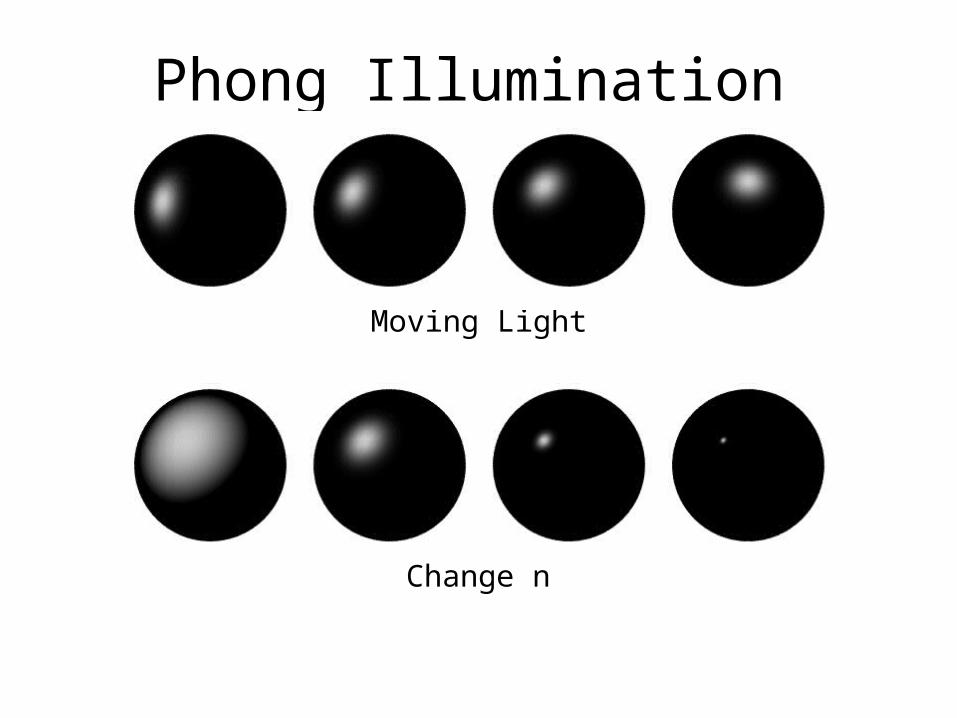
Phong Illumination
Moving Light
Change n

Putting It All Together
• Single Light (white light source)
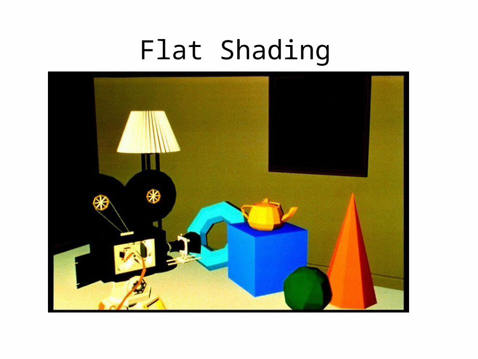
Flat Shading

Smooth Shading
• Need to have per-vertex normals• Gouraud Shading
– Interpolate color across triangles– Fast, supported by most of the graphics
accelerator cards
• Phong Shading – Interpolate normals across triangles– More accurate, but slow. Not widely supported by
hardware

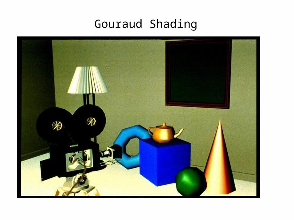
Gouraud Shading
• Normals are computed at the polygon vertices• If we only have per-face normals, the normal at each
vertex is the average of the normals of its adjacent faces
• Intensity interpolation: linearly interpolate the pixel intensity (color) across a polygon surface
Gouraud Shading

Phong Shading Model Gouraud shading does not properly handle specular
highlights, specially when the n parameter is large (small highlight).
Reason: colors are interpolated.
Solution: (Phong Shading Model)
1. Compute averaged normal at vertices.
2. Interpolate normals along edges and scan-lines. (component by component)
3. Compute per-pixel illumination.
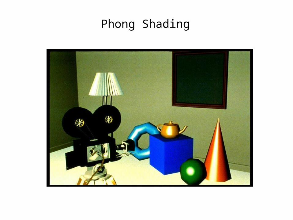
Phong Shading

What Dreams May Come
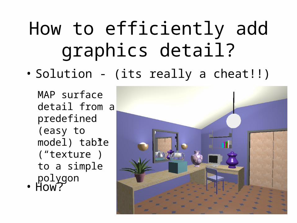
How to efficiently add graphics detail?
• Solution - (its really a cheat!!)
• How?
MAP surface detail from a predefined (easy to model) table (“texture”) to a simple polygon

Texture Mapping
• Problem #1– Fitting a square peg in a round hole– We deal with non-linear
transformations– Which parts map where?

Texture Mapping
• Problem #2– Mapping from a pixel to a “texel”– Aliasing is a huge problem!

What is a Texture?
• Given the (texture/image index) (u,v), want:– FF(u,v) ==> a continuous reconstruction
• = { R(u,v), G(u,v), B(u,v) }• = { I(u,v) }• = { index(u,v) }• = { alpha(u,v) }• = { normals(u,v) }• = { surface_height(u,v) }• = ...

RGB Textures
• Places an image on the object• “Typical” texture mapping

Opacity Textures
• A binary mask, really redefines the geometry.

Bump Mapping
• This modifies the surface normals.
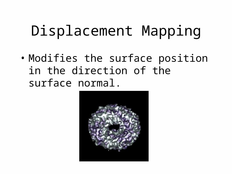
Displacement Mapping
• Modifies the surface position in the direction of the surface normal.

Texture and Texel
• Each pixel in a texture map is called a Texel• Each Texel is associated with a (u,v) 2D
texture coordinate• The range of u, v is [0.0,1.0]
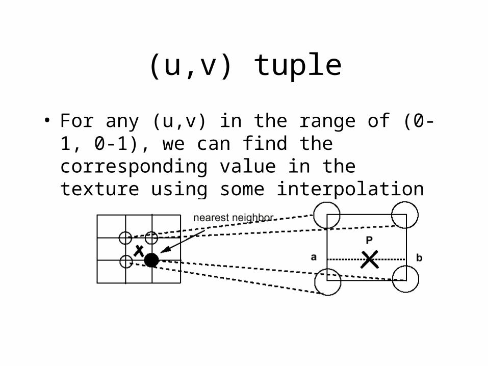
(u,v) tuple
• For any (u,v) in the range of (0-1, 0-1), we can find the corresponding value in the texture using some interpolation

Two-Stage Mapping
1. Model the mapping: (x,y,z) -> (u,v)
2. Do the mapping

Image space scan
For each yFor each x
compute u(x,y) and v(x,y)copy texture(u,v) to image(x,y)
• Samples the warped texture at the appropriate image pixels.
• inverse mapping

Texture
Image space scan
• Problems:– Finding the inverse mapping
• Use one of the analytical mappings• Bi-linear or triangle inverse mapping
– May miss parts of the texture map
Image

Inverse Mapping
• Need to transform back to world space to do the interpolation
• Orientation in 3D image space
• Foreshortening
(.5,1) (.8,1)
(.1,.6)
(.6,.2)
(.5,.7)

Texture space scan
For each vFor each u
compute x(u,v) and y(u,v)copy texture(u,v) to image(x,y)
• Places each texture sample to the mapped image pixel.
• Forward mapping

Texture space scan
• Problems:– May not fill image– Forward mapping needed
ImageTexture

Texture Mapping
• Mapping to a 3D Plane– Simple Affine transformation
• rotate• scale• translate z
y
x
u
v

Texture Mapping
• Mapping to a Cylinder– Rotate, translate and scale in the uv-plane
– u -> – v -> z– x = r cos(), y = r sin()
u
v

Texture Mapping
• Mapping to Sphere– Impossible!!!!– Severe distortion at the poles– u -> – v -> – x = r sin() cos()– y = r sin() sin()– z = r cos()

Sampling
• What we have in computer graphics is a point sampling of our scene, or:– I(x) = f(x)•ST(x)
• What we would like is more of an integration across the pixel (or larger area):– I(x) = f(x) h(x)
• What should h(x) be?

Sampling Theorem
• The Shannon Sampling TheoremA band-limited signal f(x), with a cutoff
frequency of , that is sampled with a sampling spacing of T may be perfectly reconstructed from the discrete values f[nT] by convolution with the sinc(x) function, provided:
is called the Nyquist limit.
T2
1

Sampling and Anti-aliasing
• If don’t have Nyquist rate, then aliasing artifacts.

Two possible solutions
• So far we just mapped one point, results in bad aliasing (resampling problems)
• Two possible solutions:– Super-sampling: not very good (slow!)– Low-pass filtering: popular
approaches – mipmaps, SAT

Quality considerations
• Pixel area maps to “weird” (warped) shape in texture space
pixel
u
v
xs
ys

Quality considerations
• We need to:– Calculate (or approximate) the
integral of the texture function under this area
– Approximate:• Convolve with a wide filter around the
center of this area• Calculate the integral for a similar (but
simpler) area.

Quality considerations
• the area is typically approxiated by a rectangular region (found to be good enough for most applications)
• filter is typically a box/averaging filter - other possibilities
• how can we pre-compute this?

Summed Area Table (SAT)
• Determining the rectangle:– Find bounding box and calculate its aspect ratio
pixel
u
v
xs
ys

Summed Area Table (SAT)
• Determine the rectangle with the same aspect ratio as the bounding box and the same area as the pixel mapping.
pixel
u
v
xs
ys

Summed Area Table (SAT)
• Center this rectangle around the bounding box center.
• Formula:• Area = aspect_ratio*x*x
• Solve for x – the width of the rectangle
• Other derivations are also possible using the aspects of the diagonals, …

Summed Area Table (SAT)
• Calculating the color– We want the average of the texel colors within
this rectangle
u
v+
+ -
-
(u3,v3)
(u2,v2)(u1,v1)
(u4,v4)
+ -
+-

Summed Area Table (SAT)
• To get the average, we need to divide by the number of texels falling in the rectangle.– Color = SAT(u3,v3)-SAT(u4,v4)-SAT(u2,v2)+SAT(u1,v1)– Color = Color / ( (u3-u1)*(v3-v1) )
• This implies that the values for each texel may be very large:– For 8-bit colors, we could have a maximum SAT value of
255*nx*ny– 32-bit pixels would handle a 4kx4k texture with 8-bit values.– RGB images imply 12-bytes per pixel.