Embed Size (px)
Citation preview
Review ArticleDielectric Resonator Antennas Basic ConceptsDesign Guidelines and Recent Developments atMillimeter-Wave Frequencies
S Keyrouz1 and D Caratelli12
1The Antenna Company High Tech Campus 41 Eindhoven Netherlands2Tomsk Polytechnic University 843 Sovetskaya Street Tomsk Russia
Correspondence should be addressed to S Keyrouz shadykeyrouzantennacompanycom
Received 18 July 2016 Revised 18 September 2016 Accepted 22 September 2016
Academic Editor Ahmed T Mobashsher
Copyright copy 2016 S Keyrouz and D Caratelli This is an open access article distributed under the Creative Commons AttributionLicense which permits unrestricted use distribution and reproduction in any medium provided the original work is properlycited
An up-to-date literature overview on relevant approaches for controlling circuital characteristics and radiation properties ofdielectric resonator antennas (DRAs) is presented The main advantages of DRAs are discussed in detail while reviewing the mosteffective techniques for antenna feeding as well as for size reduction Furthermore advanced design solutions for enhancing therealized gain of individual DRAs are investigated In this way guidance is provided to radio frequency (RF) front-end designers inthe selection of different antenna topologies useful to achieve the required antenna performance in terms of frequency responsegain and polarization Particular attention is put in the analysis of the progress which is being made in the application of DRAtechnology at millimeter-wave frequencies
1 Introduction
The release of the unlicensed 60GHz band and the devel-opment of 5G technologies aimed at increasing data rate onwireless communication network by a factor of 100 [1] willimpose stinging specifications (large bandwidth high gainsmall size and temperature independent performance) onthe design of the radio frequency (RF) electronics Variousfront-end antenna solutions relying on monopoles dipolesand patch antennas have been proposed for millimeter-waveapplications These antennas are characterized by small sizelow weight and low cost and can be easily integrated on chipHowever unless advanced design solutions based on the inte-gration of suitable dielectric superstrates or lensing structuresare adopted these antennas typically suffer from reducedradiation efficiency and narrow impedance bandwidth dueto the effect of lossy silicon substrate materials On the otherhand dielectric resonator antennas (DRAs) are promisingcandidates to replace traditional radiating elements at highfrequencies especially for applications at millimeter wavesand beyond This is mainly attributed to the fact that DRAs
do not suffer from conduction losses and are characterizedby high radiation efficiency when excited properly
DRAs rely on radiating resonators that can transformguided waves into unguided waves (RF signals) In the pastthese antennas have been mainly realized by making useof ceramic materials characterized by high permittivity andhigh119876 factor (between 20 and 2000) Currently DRAs madefrom plastic material (PolyVinyl Chloride (PVC)) are beingrealized The main advantages of DRAs are summarized asfollows
(i) The size of the DRA is proportional to 1205820radic120598119903 with1205820 = 1198881198910 being the free-space wavelength at theresonant frequency 1198910 and where 120598119903 denotes therelative permittivity of the material forming the radi-ating structure As compared to traditional metallicantennas whose size is proportional to 1205820 DRAsare characterized by a smaller form factor especiallywhen a material with high dielectric constant (120598119903) isselected for the design
Hindawi Publishing CorporationInternational Journal of Antennas and PropagationVolume 2016 Article ID 6075680 20 pageshttpdxdoiorg10115520166075680
2 International Journal of Antennas and Propagation
(a) (b) (c)
(d) (e) (f)
(g) (h) (i)
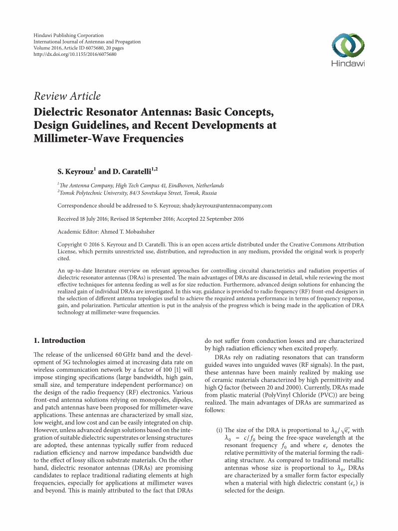
Figure 1 Different radiating structures used for dielectric resonator antennas (DRAs)
(ii) Due to the absence of conducting material the DRAsare characterized by high radiation efficiency whena low-loss dielectric material is chosen This char-acteristic makes them very suitable for applicationsat very high frequencies such as in the range from30GHz to 300GHz As a matter of fact at thesefrequencies traditional metallic antennas suffer fromhigher conductor losses
(iii) DRAs can be characterized by a large impedancebandwidth if the dimensions of the resonator and thematerial dielectric constant are chosen properly
(iv) DRAs can be excited using different techniques whichis helpful in different applications and for arrayintegration
(v) The gain bandwidth and polarization characteristicsof a DRA can be easily controlled using differentdesign techniques
The main target of this paper is to present an up-to-datereview study summarizing the most relevant techniques tocontrol circuital characteristics and radiation properties ofDRAs In this way guidance will be provided to RF front-end designers to achieve the required antenna performancein terms of gain bandwidth and polarization Differentgeometries of radiating resonators will be discussed firstturning then our attention to advantages anddisadvantages ofdifferent feeding techniques proposed so far in the literatureVarious methodologies that have been used to enhance theimpedance bandwidth and the antenna gain will be exploredFurthermore different techniques to achieve circular polar-ization are summarized Finally the most recent implemen-tation of DRAs on chip and off chip will be presented
2 Dielectric Resonators
By using a suitable excitation technique any dielectric struc-ture can become a radiator at defined frequencies It is to be
noticed that for a given resonant frequency the size of thedielectric resonator is inversely proportional to the relativepermittivity of the constitutive materialThe lowest dielectricconstant material adopted in DRA design is reported in [2ndash4] where commodity plastics with relative dielectric constantsmaller than 3 have been utilized for the realization ofsupershaped DRAs
The basic principle of operation of dielectric resonators issimilar to that of the cavity resonators [5] and is thoroughlydiscussed in literature The most two popular radiatingdielectric resonators are the cylindrical and the rectangu-lar ones They will be reviewed in this section Designequations to calculate the relevant resonant frequenciesare given More complex dielectric resonators such as thesphericalhemispherical cross-shaped and supershaped (seeFigure 1) ones will be also discussed in this section
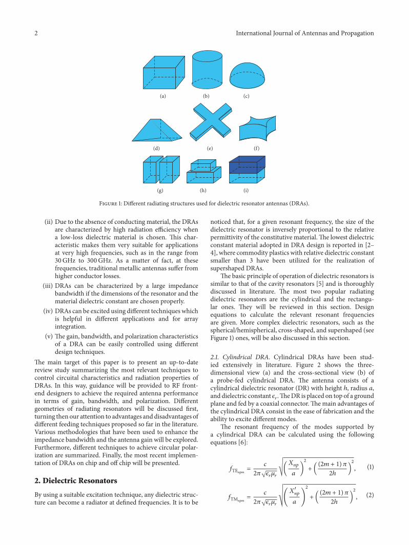
21 Cylindrical DRA Cylindrical DRAs have been stud-ied extensively in literature Figure 2 shows the three-dimensional view (a) and the cross-sectional view (b) ofa probe-fed cylindrical DRA The antenna consists of acylindrical dielectric resonator (DR) with height ℎ radius 119886and dielectric constant 120598119903TheDR is placed on top of a groundplane and fed by a coaxial connectorThemain advantages ofthe cylindrical DRA consist in the ease of fabrication and theability to excite different modes
The resonant frequency of the modes supported bya cylindrical DRA can be calculated using the followingequations [6]
119891TE119899119901119898 = 1198882120587radic120598119903120583119903radic(119883119899119901119886 )2 + ((2119898 + 1) 1205872ℎ )2 (1)
119891TM119899119901119898 = 1198882120587radic120598119903120583119903radic(1198831015840119899119901119886 )2 + ((2119898 + 1) 1205872ℎ )2 (2)
International Journal of Antennas and Propagation 3
(a) (b)
Feed point
Ground plane
Coaxial feed
h
2a
Figure 2 Three-dimensional (a) and cross-sectional view (b) of the probe-fed cylindrical DRA
1098765321 4
Radius (cm)
Reso
nant
freq
uenc
y (G
Hz)
2
25
3
1
15
05
(a)
1098765321 4
Height (cm)
Reso
nant
freq
uenc
y (G
Hz) 2
25
1
15
(b)
Figure 3 Resonant frequency as a function of the radius (a) and height (b) of a cylindrical DRA with relative permittivity 120598119903 = 10Table 1 Roots of the Bessel functions of the first kind119883119899119901
119901 119899119899 = 1 119899 = 2 119899 = 3 119899 = 4 119899 = 5119901 = 0 2404 5520 8653 11791 14930119901 = 1 3831 7015 10173 13323 16470119901 = 2 5135 8417 11619 14795 17959
where 119883119899119901 and 1198831015840119899119901 denote the roots of the Bessel functionsof the first kind and of the relevant first-order derivativesrespectively (see Tables 1 and 2)
The impact of the geometrical parameters of a cylindricalDRA (radius and height) as well as of the relative dielectricconstant (120598119903) on the resonant frequency is investigatedEquation (2) is used to calculate the resonant frequency of thefundamental model TM110 of the cylindrical DRA Figure 3shows the resonant frequency as a function of the DRArsquosradius (see Figure 3(a)) and as a function of the DRArsquos height(see Figure 3(b))The dielectric constant used to calculate the
Table 2 Roots of the first-order derivative of the Bessel functionsof the first kind1198831015840119899119901119901 119899119899 = 1 119899 = 2 119899 = 3 119899 = 4 119899 = 5119901 = 0 3831 7015 10173 13323 16470119901 = 1 1841 5331 8536 11706 14863119901 = 2 3054 6706 9969 13170 16347
resonant frequencies is set to 120598119903 = 10 It is indicated in thefigures that the resonant frequency decreases by increasingeither the radius or the height or both of them simultaneously
Figure 4 shows the effect of the relative dielectric constant(120598119903) on the resonant frequency It can be noticed that theresonant frequency of the fundamental mode decreases byincreasing the dielectric constant of theDRAThis behavior isthe most important characteristic of the DRA since it allowsdecreasing the size of the DRA by increasing its dielectricconstant It is to be noted that the impedance bandwidth isinversely proportional to the relative permittivity of the DR
4 International Journal of Antennas and Propagation
100806040200
05
1
15
2
25
0
Reso
nant
freq
uenc
y (G
Hz)
Relative dielectric constant (r)
Figure 4 Resonant frequency of a cylindrical DRAwith radius 119886 = 25 cm and height ℎ = 5 cm as a function of the relative dielectric constant
x
yd
b
ba
Subs
trate
Groundplane
Feed line
x
z
(a) (b)
Figure 5 Three-dimensional view (a) and cross-sectional view (b) of an aperture-fed rectangular DRA
Therefore the use of materials with high dielectric constantcan result in a narrowband antenna behavior
22 Rectangular DRA Figure 5 shows the three-dimensionaland cross-sectional views of a rectangular DRA fed by aslot aperture The rectangular DRA consists of a rectan-gular dielectric resonator with relative dielectric constant120598119903 The dimensions of the rectangular DR are 119886 times 119889 times ℎ(width times length times height)
The main advantage of the rectangular DRA is that it ischaracterized by three independent geometrical dimensions119886 119887 and 119889 (see Figure 5(a)) this offers more design flexibilityas compared to the cylindrical DRA Furthermore therectangular DRA is characterized by low cross-polarizationlevel as compared to the cylindrical DRA [7]
The dielectric waveguide model [8] is used to analyze therectangular DRA When the DRA is mounted on a groundplane TE modes are excited The resonant frequency of thefundamental mode TE111 is calculated by means of thefollowing equations [9]
1198910 = 1198882120587radic120598119903radic1198962119909 + 1198962119910 + 1198962119911119896119909 = 120587119886 119896119911 = 1205872119887
Air gap Ground plane
Probe feed
Hemisphere
Figure 6 Probe-fed hemispherical DRA with an air gap forbandwidth enhancement as suggested in [10]
119889 = 2119896119910 tanh(1198961199100119896119910 ) 1198961199100 = radic1198962119909 + 1198962119911
(3)
where 120598119903 is the relative dielectric constant of the materialforming the resonator
23 Hemisphere andCross-Shaped and SupershapedDRAs Inthis section attention is put also on the hemisphere and thecross-shaped and the supershaped DRAs
A probe-fed hemispherical DRA with an air gap ofhemispherical shape between the dielectric structure and theground plane is presented in [10] and is shown in Figure 6It has been found that by incorporating this gap the DRAachieves an impedance bandwidth which is nearly twice that
International Journal of Antennas and Propagation 5
Feed line
Slot
(a) (b)
90∘
270∘180∘
0∘
Figure 7 Cross-shaped DRA (a) and a sequentially fed cross-shaped DRA array (b) as suggested in [12]
without an air gapAdedicated section summarizing themostrelevant techniques to improve the impedance bandwidthwill be presented later in the paper
The authors in [11] demonstrated for the first time thepossibility of using glass dielectric resonators as light coversA dual-band hollow and solid hemispherical glass DRAs arepresented in [11] The hollow hemisphere is excited by a slotwhile the solid one is a probe-fed DRA By taking advantageof the transparency of the glass an LED was inserted into theair gap through the ground plane resulting in a DRA thatcan be used as a light cover It has been demonstrated in thepaper that the insertion of an LED inside the DRA (for bothsolid and hollow DRA) has a negligible effect on the antennaperformance
The cross-shaped dielectric resonator is mainly suggestedto design circularly polarized antenna A cross-shaped DRAas suggested in [12] is shown in Figure 7(a) To achieve awide-band circular polarization bandwidth the cross DRA shouldbe rotated 45∘ with respect to the slot and the length of thearms should be optimized [12] The individual cross-shapedDRA supports a circular polarization bandwidth of 5 withan axial ratio less than 3 dB In addition to the circularpolarization (CP) themeasured impedance bandwidth of thecross DRA reaches 16 at 10 dB return-loss level [12]
In order to achieve higher impedance bandwidth andlarger circular polarization bandwidth a sequentially fedarray of cross DRA is proposed in the same paper as shownin Figure 7(b) In this way the impedance bandwidth and theCP bandwidth are increased to 25 and 15 respectively
Recently a very similar concept has been adopted in [13]to design anmm-waveDRAThe presented design consists ofa four-by-four array of sequentially fed rectangular dielectricresonators excited by a cross-shaped slot in order to achievecircular polarization The simulated impedance bandwidthextends from 269GHz to 337 GHz whereas the simulatedaxial ratio bandwidth at 3 dB level extends from 241 GHz to311 GHz
A plastic-based supershaped DRA has been presented in[2ndash4] and is shown in Figure 8 The reported impedancebandwidth is extended to 74 by using a supershapeddielectric resonator
Feed point Ground plane
Figure 8 Probe-fed supershaped DRA [2]
The main advantage of the presented supershaped DRAis that it uses plastic (PolyVinyl Chloride (PVC)) as dielectricmaterial which makes it very cost effective and easily manu-facturable
In addition to the basic dielectric resonators that havebeen discussed in this section numerous attempts have beenperformed to combine different dielectric resonators togetherin order to optimize antenna performance Figures 1(d) 1(e)and 1(f) show different configurations of combined DRAsThe advantages of combining different DRs will be presentedlater in the paper but first different feeding structures ofDRAswill be discussed in the following section
3 Feeding Structures
One of the main advantages of DRA technology is thatvarious feeding techniques can be used to excite the radiatingmodes of a dielectric resonator
31 Probe-Fed DRA The probe-fed DRA is among the firstreported DRAs [10 14] and is shown in Figure 9 In this con-figuration the DR is directly disposed on the ground planeand is excited by a coaxial feed through the substrate Thecoaxial probe can either penetrate the DR (see Figure 9(a))or can be placed adjacent to the DR as shown in Figure 9(b)
6 International Journal of Antennas and Propagation
Probe feedProbe feed
Ground plane
(a) (b)
Figure 9 Probe-fed rectangular DRA
Substrate
x
Ground plane
Microstriptransmission line
Conformal transmission line
(a) (b)
Figure 10 Three-dimensional view of conventional (a) and conformal (b) microstrip transmission line feeding networks
By optimizing length and position of the feeding probethe input impedance of the DRA can be tuned [15] andconsequently the resonance frequency can be controlledThemain benefit associated with a probe penetrating the DRA(see Figure 9(a)) is that it provides high coupling to the DRwhich in turn results in high radiation efficiency The maindrawback of such configuration is that a hole needs to bedrilled in the DRA The dimensions of the drilled hole needto match the dimensions of the probe (length and radius)otherwise the effective dielectric constant of the resonatorwill be affected this causing a shift in the resonance frequencyof the antenna It is to be noticed furthermore that drillinga hole in the DR complicates the manufacturing process andmakes it more expensive
A reduced manufacturing complexity is achieved byplacing the excitation probe adjacent to the DR (see Fig-ure 9(b)) This technique is cost-effective but results in asmaller coupling to the DR which eventually affects theradiation characteristics of the structure
For high-frequency applications where the antenna ismanufactured on a PrintedCircuit Board (PCB) or is directlyintegrated on chip probe-fed DRAs are not practical
32 Microstrip Transmission Line-Fed DRA Another wayto feed the DRA is by using printed transmission linesFigure 10 shows the three-dimensional view of a rectangularDRA fed by a microstrip line (see Figure 10(a)) and by aconformal transmission line (see Figure 10(b)) In conven-tional microstrip line-fed DRAs the dielectric resonator isdirectly placed on the transmission line that is printed onthe PCB substrate One of the first reported DRAs fed by
a microstrip line is reported in [16] It has been shown in[16] that the overlap distance 119909 (see Figure 10(a)) determinesthe coupling strength and the specific mode that is excitedby the transmission line The strongest coupling occurswhen 119909 is slightly shorter than one-quarter of a dielectricwavelength of the resonance frequency The main drawbackof the microstrip transmission line feed is that the feedingline is not isolated from the dielectric resonator which canaffect the radiation performance of the DRA In additionwhen placing the dielectric resonator directly on the top ofa transmission line an undesired air gap is created betweenthe resonator and the substrate of the PCB
In a conformal transmission line-fed DRA the resonatoris placed directly on the PCB substrate and the feedingmicrostrip is bent over the resonator as shown in Figure 10(b)By using this configuration the input transmission line isintegrated with the DR without creating an air gap Theshape of the transmission line that is bent over the dielectricresonator can be optimized to improve the performanceof the DRA As an example a conformal elliptical patchthat feeds an U-shaped DRA is suggested in [17] where animpedance bandwidth of 72 is achieved
33 Coplanar-Waveguide-Fed DRA The coplanar waveguideexcitation was first introduced in [18] where a coplanarwaveguide (CPW) circular-loop network that feeds a cylin-drical DRA is presented A rectangular DRA fed by a similarstructure is shown in Figure 11(a) The main advantage of theCPW excitation is that the coupling slot that is underneaththe dielectric resonator can be modified to optimize theperformance of the DRA In [19] the circular-loop feeding
International Journal of Antennas and Propagation 7
CPW transmission line
Substrate
Ground plane
Capacitive slot
Inductive slot
(a)
(b)
(c)
Figure 11 Rectangular DRA fed by a CPW circular-loop network (a) Inductive slot feed (b) Capacitive slot feed (c)
Feed line
x
y
Slotxd
yd
Figure 12 Top view of an aperture-coupled hemispherical DRA as presented in [20]
network is replaced by an inductive slot (see Figure 11(b)) andby a capacitive slot (see Figure 11(c)) in combination with ahemispherical DRA It has been shown that the capacitiveslot provides an additional resonance which results in adual-band behavior with two resonances associated with theDR and the feeding slot itself respectively CPW feedingstructures are widely used for millimeter-wave applicationsespecially when the DRA is integrated in a system on chip(SoC) As amatter of fact by usingCPW transmission lines itis possible to achieve high antenna efficiency since the groundplane separates the dielectric resonator from the lossy siliconsubstrate
34 Slot-Fed DRA The most popular feeding technique forDRAs is via a slot in the ground planeThis excitationmethodis known as aperture coupling The guided wave propagatingalong the transmission line is coupled through the slot to theresonant modes of the DR
Figure 12 shows the top view of an aperture-coupledhemispherical DRA as presented in [20] The effect of theslot displacements 119909119889 and 119910119889 (see Figure 12) from the centerof the DRA is investigated in [20] It has been found thatbest resonance (impedance matching) is achieved when theDR is perfectly centered on top of the slot (119909119889 = 119910119889 = 0)The main advantage of this method is that it avoids a directelectromagnetic interaction between the feed line and theDRA as indicated in Figure 13 By using this topology thespurious radiation from the feeding network can be reducedthus enhancing the polarization purity of the DRA Thedrawback of such excitation method is that the slot length
h1
h2
Feed line
Substrate
r1
r2
Figure 13 Cross-sectional view of a two-layer rectangular DRA forsize reduction as suggested in [21]
should be around 1205822 which is a challenge to realize at lowerfrequencies while keeping the size of the DRA compact
4 DRA Size Reduction Methods
The two most common techniques to minimize the size of aDRA are either to use material with high dielectric constantor to insert a metal plate in the symmetry plane of the DRThese techniques are reviewed in this section
41 High Relative Dielectric Constant (120598119903) In general thesize of the DRA is inversely proportional to the dielectricconstant (120598119903) of the resonator as seen in Figure 4 So inorder to decrease the size of the DRA a material with a highdielectric constant can be chosen however this should becarefully done since the impedance bandwidth can be affectednegatively by the choice of the dielectricmaterial In [9] a low-profile rectangular DRA (00261205820) with very high relative
8 International Journal of Antennas and Propagation
Probe feed
Ground plane
x
z
bb
a a2
E-fieldTE111mode
(a) (b)
Figure 14 Cross-sectional view of a probe-fed rectangular DRA (a) and its miniaturized version (b) by placing a conducting plate at 119909 = 1198862
permittivity (120598119903 = 100) is presented It is demonstrated thateven when using such a high dielectric constant materiala reasonable impedance bandwidth of 11 to 33 can beachieved
To overcome the limitation related to reduced bandwidtha multilayer DRA topology can be adopted By optimizingthe dielectric constant and height of each layer the DRAparameters (size impedance bandwidth and gain) can becontrolled and optimized Figure 13 shows the cross-sectionalview of a two-layer rectangular DRA as suggested in [21]Thisconfiguration offers additional degrees of freedom (1205981199032 andℎ2) in the design of a DRA as compared to the single-layerantenna configuration Using this methodology the authorsin [21] were able to design a low-profile rectangular DRA(having height of 011205820) with an impedance bandwidth of40 and an average gain of 9 dBi
42 Metal Plate along Symmetry Plane The second designtechnique to minimize the size of a DRA consists in theintegration of metal plates along the relevant symmetryplanes as it easily follows from the application of imagetheory [22] Figure 14(a) shows the cross-sectional viewof a probe-fed rectangular DRA with length 119886 and height119887 Its corresponding miniaturized version is shown inFigure 14(b)
As indicated in the figure the size of the DRA can behalved by placing a conducting plate along the central cross-section of the dielectric resonator at 119909 = 1198862 The effectof the miniaturization on the resonant frequency and theimpedance bandwidth of a DRA was investigated in [23] andthe results are summarized in Table 3The dimensions 119886 and119887 listed in the table are specified in accordancewith Figure 14One can clearly notice that the insertion of the metal plateallows halving the volume of the DRA but at the same timeresults in a reduction of the available impedance bandwidthby a factor of three It should be mentioned that when aconducting plate is used the position as well as the lengthof the feeding probe should be fine-tuned in order to matchthe input impedance of the antenna at the desired resonantfrequency
Table 3 Effect of the miniaturization of a rectangular DRA [23]
119886(mm) 119887(mm) Volume(cm3) 120598119903 Conductingplate
1198910(GHz) Impedancebandwidth
88 40 704 12 No 122 1644 40 352 12 Yes 0918 54
Table 4 Measured gain of a DRA with and without SMSH [25]
Frequency (GHz) 58 59 60 61 62Gain without SMSH (dBi) 14 28 38 42 27Gain with SMSH (dBi) 79 88 82 82 69
Similarly the size of a cylindrical DRA can be reducedby 75 by placing a Perfect Electric Conductor (PEC) and aPerfect Magnetic Conductor (PMC) at the symmetry planesof cylinder as shown in [24]
5 DRA Gain Enhancement Methods
The most straightforward approach to increase the gain ofa DRA is by arraying individual DRAs The gain of a DRAarray increases by increasing the number of DR elements inthe array However this approach is not the main goal of thissection Attention is put here on two alternative techniques toenhance the gain of a single DRA element
51 Integration of Additional Structures An efficient way toincrease the gain of a DRA relies on the integration of addi-tional structures useful to focus the antenna radiation in onedirection and increase in this way its gain A straightforwardexample of suchdesign approach is the surfacemounted shorthorn (SMSH) DRA presented in [25] A cross-sectional viewof the SMSH is shown in Figure 15
The suggested DRA consists of a slot-fed rectangulardielectric resonator with four additional inclined metallicplates used to form a horn-like structure The effect of theSMSH structure on the DRA gain is quantified in Table 4The figures of merit listed in the table are taken from [25]
International Journal of Antennas and Propagation 9
Surface mounted short horn
(SMSH)
DRA
SlotSupport material
Microstrip feed line
Ground plane
Figure 15 A surface mounted short horn (SMSH) configuration assuggested in [25]
Lens
DR
Reflector
Figure 16 High-gain mushroom-shaped DRA structure as pre-sented in [27]
It can be noticed that the addition of the SMSH results ina 44 dB increase of the antenna gain at 6GHz The sameapproach has been used in [26] where a cylindrical DRAintegrated on a periodic substrate composed of circularmetalstrips is presented By optimizing the distribution of the stripsaround the DRA a 3 dB enhancement of the antenna gain atthe design frequency has been achieved
Recently a high-gain mushroom-shaped DRA has beenpresented in [27] The suggested design is shown in Figure 16and consists of a probe-fed hollow cylindrical DRA Aspherical-cap lens is placed on top of the cylindrical DRA toincrease the antenna gain It has been shown that the additionof the lens on top of the cylinder will increase the gain by 3 dBto 58 dBThe front-to-back ratio is increased between 46 dBand 88 dB across the operational frequency band In additionto the lens the suggested cylindrical DRA is surrounded bya metal truncated-cone reflector The measured antenna gainof the suggested DRA is larger than 10 dBi between 45GHzand 95GHz with a maximum of 16 dBi around 85GHz
52 Excitation of Higher-Order Modes The second methodto increase the gain of an individual DRA is by excitingthe relevant higher-order modes thus making the DRAelectrically larger with respect to its fundamental resonantfrequency It has been shown in [28] that when the TE12057515mode of the rectangular DRA is excited a 6 dB increaseof the antenna directivity is achieved as compared with the
directivity obtained when exciting the fundamental resonantmode (TE12057511)
The design of a pattern-reconfigurable cylindrical DRAwith high gain resulting from the excitation of higher-orderHEM21(1+120575) modes has been reported in [29]
Recently a cylindrical DRAwith a measured peak gain of116 dBi has been reported in [30] In this design the higher-order HEM133 mode of a cylindrical dielectric resonator isexcited in order to achieve the desired antenna performance
6 Circular Polarization
One of the advantages of DRAs is that their polarization canbe easily controlled In this section different techniques todesign circularly polarized DRAs are reviewed
61 Dual-Feed Excitation Exciting a DRA by using two portswith a 90∘ phase shift is a simple but effective means forachieving circular polarization of the radiated electromag-netic field Figure 17 shows a probe-fed cylindrical DRArelying on the mentioned approach [31] The measured axialratio along the broadside direction of this antenna has beenreported to be 045 dB thus indicating a very good circularpolarization property
The same design strategy has been applied in [32] wherea cylindrical DRA is excited by two conformal microstriptransmission lines The suggested design offers a 3 dB axialratio bandwidth of 40
62 Single-Feed Excitation Circularly polarized DRAs canbe designed also by using a single feed placed at a locationwhere two orthogonal modes can be excited This techniquehas been applied in [33] in combination with a circular sectordielectric resonator The probe feed is placed between thecenter of the sector (where the TM21120575 is excited) and the edgeof the sector (where the TM11120575) A 3 dB axial ratio bandwidthof 10 has been measured for the DRA presented in [33]
In order to achieve circular polarization in slot-fedDRAsthe dielectric resonator and the feeding slot are to be properlyrotated relative to each other so that two orthogonal modescan be excited with the desired phase difference Figure 18shows the cross-sectional view (a) and the top view of a slot-fed rectangular DRA As indicated in Figure 18(b) the DRAis rotated with an angle 120601 with respect to the slot When120601 = 45∘ two orthogonal modes with 90∘ phase differencescan be excited which results in a circularly polarized patternThis technique has been used in [34 35] to design circularlypolarized rectangularDRAswith a 3 dB axial ratio bandwidthof 18 and 3 respectivelyThe same strategy has been usedin [12] to excite the cross-shaped DRA shown in Figure 7
A novel circularly polarized three-layer stacked DRAhas been presented in [36] Each layer is made out of ahomogeneous dielectric material with relative permittivity120598119903 = 107 and rotated by an angle of 120601 = 30∘ relative to theadjacent one In this way a 3 dB axial ratio bandwidth of 6has been obtained in combination with a wide impedancebandwidth of 21
10 International Journal of Antennas and Propagation
Groundplane
DRA
Probe 1
Probe 2
= 90∘
= 0∘
(a)
Probe 1
Probe 2
Substrate
Phase shift
50Ω feed
90∘
(b)
Figure 17 Circularly polarized dual-fed cylindrical DRA as suggested in [31]
Substrate
Feed line
Slot
x
y
(a) (b)
Figure 18 Cross-sectional view (a) and top view (b) of a rotated rectangular DRA as suggested in [34 35]
CPW transmission line
Grounded parasitic patch
Parasitic patchGroundplane
L
W
Subst
rate
Feeding slot
(a) (b)
LpWp
Figure 19 Three-dimensional view of a cylindrical DRA with a grounded parasitic patch (a) as introduced in [40] and three-dimensionalview of a rectangular DRA with a parasitic patch placed on its top face (b) as presented in [39]
Instead of rotating the DR itself location and geometry ofthe feeding slot can be optimized in order to achieve circularpolarization This technique has been used in [37 38] wherecross-shaped slots have been proposed for the mentioneddesign goal In particular the dual-band circularly polarizedrectangular DRA presented in [37] features measured 3 dBaxial ratio bandwidths of 97 and 20 respectively in thetwo operational frequency ranges In [38] an offset cross-shaped slot has been used to excite a cylindrical DRA thusachieving a measured 3 dB axial ratio bandwidth of 46
63 Single-Feed Excitation with Parasitic Metal Strip An-other method for exciting two orthogonal modes and enforc-ing a circular polarization of the radiated electromagnetic
field relies on the use of parasitic metal stripspatchesattached to the surface of the dielectric resonator Theparasitic metallic element introduces an asymmetry in theDRA structure which eventually leads to the excitation oftwo orthogonal modes with the desired phase difference [39]The parasitic patch can be as shown in Figure 19(a) or keptfloating on the top of the DRA as shown in Figure 19(b)An example of circularly polarized rectangular DRA withfloating parasitic metal strip placed on its top face is reportedin [39] By adjusting the width119882 and length 119871 of the strip(see Figure 19(b)) the axial ratio of the antenna can be easilytuned By virtue of this design approach a 2 dB axial ratiobandwidth of 6 can be achieved
A circularly polarized cylindrical DRA with groundedparasitic strip has been presented in [40] and shown in
International Journal of Antennas and Propagation 11
2a
Ground plane
Cylindrical DRA
Substrate
h
(a) (b)
Figure 20 Top (a) and cross-sectional view (b) of a perforated DRA as suggested in [46]
Figure 19(a) It has been demonstrated that the location ofthe parasitic patch is not very critical for the purity of thecircular polarization (see Figure 19(a)) On the other handthe axial ratio of the antenna is strongly affected by the lengthof the patch 119871119901 whereas the width of the parasitic patch119882119901 plays a none significant role By tuning 119871119901 and 119882119901 thepolarization properties of the DRA can be tuned Similarconclusions have been reported in [41] where a rectangularDRA with grounded parasitic patch has been investigated
7 Impedance Bandwidth EnhancementMethods of DRAs
In this section different techniques useful to broaden theimpedance bandwidth of a DRA are summarized
71 Combining Different Dielectric Resonators Dielectric res-onators can be combined together to broaden the impedancebandwidth of the resulting DRA structure Figures 1(g) 1(h)and 1(i) show different configurations of combined DRAs Byplacing multiple dielectric resonators of different dimensionson top of each other (see Figure 1(h)) different modes canbe excited In this way dual-band or broadband behaviorcan be achieved By using such approach a staircase-shapedDRA has been designed and presented in [42 43] A 10 dBreturn-loss impedance bandwidth of 366 from 756GHzto 1095GHz has been obtained by using the three-stepstaircase-shaped DRA proposed in [42] A very similar con-figuration consisting of a two-step staircase-shaped probe-fedDRA has been presented in [44] The measured impedancebandwidth of the suggested design is 44 and covers afrequency range from 745GHz to 116 GHz Recently adual-band circular DRA with staircase geometry has beenproposed in [45]
An alternative design approach useful to achieve largeimpedance bandwidths consists in the tapering of thepermittivity distribution within the DR This can be doneeither by combining multiple layers with different dielectricconstants or by drilling holes of different diameters into theDR in order to taper the effective permittivity of the structureThe geometry of a perforatedDRA is shown in Figure 20Thisconcept has been investigated in [46] where an impedancebandwidth of 267 (120598119903 = 102) has been reported
Dual-band orwide-band characteristics can be easily syn-thesized by exciting different resonant modes in multilayered
Minkowski Koch Sierpinski curve
Figure 21 Different fractal boundary structures proposed andsimulated in [50]
DRAs consisting of different dielectric laminates with prop-erly selected permittivity A cross-sectional view of a two-layer DRA is shown in Figure 13 It has been shown that when1205981199032 (dielectric constant of the bottom layer) is smaller than1205981199031 (dielectric constant of the top layer) an impedance band-width of 40 at 10 dB return-loss level can be obtained [21]Based on these findings the antenna impedance bandwidthcan be further broadened by using an air gap (1205981199032 = 1) asbottom layer [47 48] Both DRAs presented in [47 48] arefed by a tapered strip printed on one side of the dielectricresonator the relevant impedance bandwidth being of 120(26ndash11 GHz) and 96 (213ndash608GHz) respectively
An alternative antenna topology that can feature wideimpedance bandwidth or dual-band operation is the oneconsisting of two dielectric resonators next to each otherand separated by a gap as shown in Figure 1(g) This designapproach has been suggested in [49] where two rectangularDRs are placed on the top of edges of the feeding slotproduced in the antenna ground plane By optimizing thedimensions of the dielectric resonators the desired dual-band or wide-band behavior can be synthesized
72 Shaping the Dielectric Resonator When shaping the di-electric resonator different modes can be excited and in thisway a wide impedance bandwidth achieved A U-shapedDRA (120598119903 = 98) fed by means of a conformal ellipticalpatch has been proposed in [17] The suggested design offersa 72 impedance bandwidth in the frequency range between382GHz and 812GHz
A CPW-fed fractal DRA topology has been proposedin [50] in order to excite higher-order modes with quasi-degenerate resonant frequencies resulting in a wide impe-dance bandwidth Different fractal DRAs with MinkowskiKoch and Sierpinski profiles have been investigated in [50](see Figure 21) The numerically predicted characteristics
12 International Journal of Antennas and Propagation
Table 5 Numerically Simulated Characteristics of fractal-basedDRAs as Reported in [50]
DRA profileResonantfrequency(GHz)
Impedancebandwidth(MHz)
Gain(dBi)Minkowski 659 2870 412Koch 68 2540 351Sierpinskicurve 80 1610 105
Feeding probe
Dielectric hemispherical resonator
Ground plane
Figure 22 Cup-shaped inverted hemispherical DRA as suggestedin [51] for impedance bandwidth enhancement
of the mentioned fractal-based DRAs are summarized inTable 5 One can notice that theMinkowski DRA features thehighest gain and largest impedance bandwidth as comparedto the Koch and Sierpinski ones The simulated results forthe Minkowski DRA have been verified by experimentalmeasurements and in this way an impedance bandwidth of64 (from 552GHz to 1072GHz) has been demonstrated
An alternative antenna topology that provides a largeimpedance bandwidth is the supershaped DRA shown inFigure 8 By optimizing the shape of the DRA an impedancebandwidth of 74 (from 67GHz to 14GHz) has beenachieved To this end a plastic-based dielectric resonatorhaving relative permittivity 120598119903 = 273 has been used [2]
Finally the cup-shaped inverted hemispherical DRAdesign presented in [51] is to bementioned in this surveyTheconfiguration of the suggested DRA is shown in Figure 22The impedance bandwidth of such DRA is 83 around thecentral resonant frequency of 23 GHz The permittivity ofthe dielectric material adopted for the manufacturing of saidantenna is 120598119903 = 9273 Effect of the Feeding Slot In order to increase the im-pedance bandwidth of an aperture-fed DRA an annular slotcan be used as proposed in [40 52] The configuration of theannular slot is shown in Figure 23 Using this solution theimpedance bandwidth can be increased to 18 while using adielectric material with relative permittivity 120598119903 ≃ 10
The annular slot-based approach has been extended in[53] becoming a circular aperture excited by amicrostrip linewith fork-like tuning stub The configuration of the feedingnetwork and the circular aperture are shown in Figure 24(a)In order to suppress the spurious backward radiation fromthe circular aperture a hollow hemispherical backing cavityis placed beneath the tuning fork In this way an impedance
bandwidth of 38 has been achieved in combination with acylindrical DRA having relative permittivity 120598119903 ≃ 10
An alternative feeding aperture geometry which allowsbroadening the impedance bandwidth of a DRA is the U-shaped slot shown in Figure 24(b) [54] This solution has theadvantage of having two arms (119871119860 and 119871119862) and therefore anadditional degree of freedom in the design and optimizationof the DRA feeding By fine-tuning the length and the widthof each arm of the slot the impedance bandwidth andorthe polarization of the antenna can be controlled It hasbeen shown in [54] that the length ratio of the two armsshould be close to the unity in order to achieve a beneficialenhancement of the impedance bandwidth On the otherhand a large length ratio results in a circular polarization ofthe antenna
74 Hybrid Approach Hybrid design approaches rely on thecombination of DRAs and radiating patchslot antennas Bytuning the resonant frequency of the radiating patchslotantenna in order to be close to that of the combined DRA awide impedance bandwidth can be achieved A hybrid DRAresulting from the combination of a ring-shaped dielectricresonator and a circular microstrip patch fed by a resonantslot is presented in [55] and shown in Figure 26 Themeasured impedance bandwidth of this hybrid DRA is suchto cover the 60GHz unlicensed frequency band from 57GHzto 65GHz Another hybrid DRA design solution relying onthe combination of amonopole antenna with a ring dielectricresonator is proposed in [56] (see Figure 25(a)) Such antennastructure is characterized by three main resonances Twoof such resonances are associated with the monopole andthe dielectric ring resonator respectively whereas a thirdintermediate resonance results from the combination of theother ones The operational frequency band of the physicalprototype presented in [56] extends from 5GHz to 13GHzwith the magnitude of the input reflection coefficient smallerthan minus10 dB Similar hybrid DRAs with the dielectric ringresonator replaced by one having conical or hemispherical(see Figure 25(b)) geometry have been presented in [57]In particular by using a hemispherical DR the impedancebandwidth of the radiating structure has been increased to126 covering in this way the frequency range between5GHz and 21GHz
A hybrid DRA combining a rectangular DR and a CPWinductive slot (see Figure 11(b)) has been introduced in [58]in order to achieve a wide-band behavior As a matter offact the resonant frequencies of the rectangular DR and ofthe inductive slot are designed to be 54GHz and 58GHzrespectively resulting in a measured impedance bandwidthof 23 between 486GHz and 615GHz
A similar design approach is adopted in [59] where ahybrid DRA resulting from the combination of a radiatinginductive slot and a cylindrical DR has been proposedThe two resonances associated with the feeding slot andthe dielectric resonator respectively result in a dual-bandbehavior with measured impedance bandwidths of 9 (from3300MHz to 3612MHz) and 48 (from 4681MHz to4912MHz) respectively
International Journal of Antennas and Propagation 13
Feed line
Feed line
Annular slot
Ground plane
Cylindrical DRA
Substrate
h2a
(a) (b)
Figure 23 Top (a) and cross-sectional view (b) of a rectangular DRA excited by an annular slot
Feed line
Circular aperture Fork-like
tuning stub
(a)
Hemisphere
U-slot
LA
LB
LC
(b)
Figure 24 Circular aperture slot (a) as introduced in [53] and U-shaped slot (b) as investigated in [54]
Monopole
Dielectric ring resonator
(a)
Dielectric hemisphericalresonator
Monopole
(b)
Figure 25 Cross-sectional view of a hybrid DRA consisting of a monopole and a ring DR (a) as suggested in [56] Cross-sectional view of ahybrid DRA consisting of a monopole and a conical DR (b) as suggested in [57]
8 Millimeter-Wave DRAs
One of the intrinsic characteristics of DRAs is the absence ofconduction losses This property makes DRAs very suitablefor high-frequency applications In this section major andmore recent advances of DRA technology at mm-wavefrequencies are summarized
81 Off-Chip DRA At millimeter-wave frequencies and be-yond the size of dielectric resonators become very smallwhich makes the manufacturing of the DRA challengingwithout resorting to expensive fabrication techniques In
order to overcome this limitation and at the same timeimprove antenna gain electrically large DRAs exploitinghigher-order modes are to be adopted
A hybrid approach combining the excitation of higher-order modes with the radiation from the antenna feed hasbeen presented in [55] Figure 26 shows the top view (a) andthe cross-sectional view (b) of the suggested design resultingfrom the combination of a ring-shaped dielectric resonatorand a circular microstrip patch fed by a resonant slot TheHEM15120575 mode of the DRA is excited A constant measuredantenna gain of approximately 12 dBi is reported for theproposed hybrid DRA [55] The antenna covers the 60GHz
14 International Journal of Antennas and Propagation
Ground plane
Ring DRA
Circular microstrippatch
r1
r2
r3
(a) (b)
Figure 26 Top view (a) and cross-sectional view (b) of a hybrid ringpatch DRA as introduced in [55]
Table 6 Most Recent Advances in dielectric resonator antennas for millimeter-wave Applications
ReferenceYear DRAtopology
Relativepermittivity
Feedingmechanism Technology Frequency
(GHz)
Impedancebandwidth
()
Gain(dBi)
[55]2009 Ring withmicrostrip Patch 10 Coupling slot PCB 60 15 12
[61]2010 Cylindrical 10 Coupling slot PCB 60 24 55[62]2011 Rectangular 10 Coupling slot PCB 24 38 63
[63]2011 Rectangular 102 CapacitiveslotCPW PCB 60 174 102
[64]2012 Cylindrical 102 Coupling slot PCB 60 143 157[65]2013 Cylindrical 102 Coupling slot PCB 60 229lowast 86[66]2016 Cylindrical 102 Coupling slot PCB 60 10lowast mdash
[60]2016 Ring withmicrostrip Patch 102 Coupling slot PCB 60 12 165
[67]2007 Rectangular 48 CPW Integrated on chip 60 28 32
[68]2008 Cylindrical 42 FoldeddipoleCPW Integrated on chip 277 98 1
[69]2010 Rectangular 38 H-slotCPW Integrated on chip 35 12 05
[70]2012 Rectangular 10 MeanderslotCPW Integrated on chip 130 12 27
[70]2012 Two-layerrectangular 10 Meander
slotCPW Integrated on chip 130 11 47
[71]2013 Rectangular 126 Coupling slot Integrated on chip 605 61 6
[72]2015 Rectangular 98 E-shapedCPW Integrated on chip 340 12 10
[73]2015 Circular 126 DipoleCPW Integrated on chip 60 378 7lowast is estimated from graph
unlicensed frequency band (from 57GHz to 65GHz) with anearly flat gain of about 12 dBi A similar concept has beenrecently proposed in [60] where the resonances of a circularpatch and a ring-shapedDRA are combined together in orderto achieve a broadbandbehaviorwhile improving the antennagain An impedance matching bandwidth of 12 (from57GHz to 64GHz) has been predicted numerically for suchradiating structures The simulated antenna gain is 165 dBithis being reported as the largest gain level featured by asingle-element DRA The characteristics of the consideredantenna are listed in Table 6
A class of linearly and circularly polarized cylindricalDRAs fed by substrate integrated waveguides is presented in[61] The proposed DRAs are designed in such a way as toresonate at 60GHzThemeasured impedance bandwidths are24 and 45 for the linearly and circularly polarized DRAsrespectively The performance characteristics of the linearlypolarized DRA are summarized in Table 6
The effect of the fabrication tolerances on the frequencyshift of higher-order modes is investigated in [62] and listedin Table 7 It is clearly indicated in the table that higher-ordermodes are less affected by fabrication errors which is very
International Journal of Antennas and Propagation 15
Table 7 Simulated frequency shift of higher order modes of arectangular DRA due to fabrication tolerances [62]
Fabrication error(mm)
TE111 modeΔ119891 ()TE115 modeΔ119891 ()
TE119 modeΔ119891 ()001 038 021 012005 204 100 07401 399 183 141
Table 8 Comparison between the volume of DRAs excited at24GHz by TE111 TE115 and TE119 modes
Resonant modeDimensions119886 times 119889 times 119887
(mm)
DR volume(mm3)
TE111 25 times 25 times 21 1313TE115 40 times 40 times 61 976TE119 42 times 42 times 107 18875
encouraging especially for mm-wave applications where thesize of the DRA becomes very small
The reduced sensitivity of higher-order modes to fabri-cation errors can be readily understood by observing thata DRA driven on a higher-order mode is physically muchlarger as compared to the same DRA when operating onthe relevant fundamental mode In order to highlight thispoint the volume of rectangular DRAs excited at the higher-order modes TE115 and TE119 is compared in Table 8 to thatof a DRA operating on the TE111 mode Said DRAs are alldesigned in order to resonate at the frequency of 24GHzAs itcan be easily noticed in Table 8 the rectangular DRAs excitedat TE115 and TE119 modes are respectively 74 and 144times bulkier than the equivalent radiating structure excitedat its fundamental mode Additional characteristics of thementioned DRA driven on the TE119 mode are summarizedin Table 6
The gain of a singleDRA element can be further increasedby placing a superstrate on the top of the DR This approachhas been suggested in [63] A cross-sectional view of thesuggested antenna topology is shown in Figure 27 where acoplanar waveguide with capacitive slot (see Figure 11(c)) isused to excite the DRA The radiating structure proposedin [63] is designed to resonate in the 60GHz unlicensedISM frequency band It has been shown in particular thatthe antenna gain can be tuned by changing the distance dsbetween the superstrate and the ground plane (see Figure 27)A large impedance bandwidth of 174 is obtained thanks tothe combined excitation of the resonances of the DRA (fun-damental and higher-order modes) as well as of the feedingslot The integration of the superstrate allows improving theantenna gain by 9 dB as compared to a conventional DRAwithout superstrate In this way a peak gain of 1444 dBi at60GHz has been achieved
An extensive study on the effect of dielectric super-strates in combination with millimeter-wave DRAs has beenreported in [64] The considered antenna topologies areshown in Figure 28The first antenna consists of a cylindrical
Superstrate
dsDRAGround
plane
CPWfeed line
Figure 27 Rectangular DRAwith superstrate for gain improvementas suggested in [63]
Table 9 Performance comparison between the DRAs shown inFigure 28
Antenna 1 Antenna 2 Antenna 3 Antenna 4Impedancebandwidth () 365 1436 135 1436
Antenna gain 60GHz (dBi) 69 78 1436 157
DRA fed by a coupling slot (see Figure 28(a)) In the secondantenna configuration (see Figure 28(b)) an intermediatesubstrate is integrated between the cylindrical DR and thecoupling slot By adding this dielectric layer one gains anextra degree of freedom in the design that can be used totune the frequency response of the DRA The third antennatopology studied in [64] and illustrated in Figure 28(c) relieson the integration of a suitable superstrate above the DRThis concept was already presented by the same authors in[63] The superstrate results in a focusing process of theelectromagnetic field along the broadside direction of theDRA and thanks to that in an increase of the antenna gain[63] The fourth antenna configuration investigated in [64](see Figure 28(d)) is characterized by a square ring FrequencySelective Surface (FSS) printed on the superstrate The FSSlayer provides an effective means to further increase therealized gain of the antenna The performances of the fourantennas shown in Figure 28 are summarized in Table 9It can be noticed that the integration of an intermediatedielectric substrate has a detrimental effect on the impedancebandwidth of the antenna On the other hand using asuperstrate has a negligible impact on the bandwidth whilegreatly improving the gain of the basic DRA structureFinally the FSS layer enables an additional gain enhancementof about 36 The characteristics of the resulting antennaconfiguration 4 as shown in Figure 28(d) are summarized inTable 6
A novel cylindrical DRA for 60GHz applications hasbeen presented in [65] In such design the dielectric res-onator is surrounded by five periods of mushroom-like Elec-tromagnetic Band Gap (EBG) elements in order to achieve a3 dB antenna gain enhancement while suppressing undesiredsurface waves
The integration of a suitable FSS wall has been suggestedin [66] in order to decrease the mutual coupling between
16 International Journal of Antennas and Propagation
DR
(a) Antenna 1
DR
Intermediate substrate
(b) Antenna 2
DR
Superstrate
ds
(c) Antenna 3
DR
Ring FSS
(d) Antenna 4
Figure 28 Millimeter-wave DRA topologies presented in [64]
(a) (b)
Figure 29 Front side (a) and back side (b) of the FSS unit cell useful to reduce the mutual coupling between DRAs [66]
DRAs The proposed design is based on the combinationof a Jerusalem-cross slot and a fan-like structure printedon the front and back side of the individual cell of theFSS respectively as shown in Figure 29 It has been proventhat when such FSS wall is inserted between two cylindricalDRAs operating in the frequency band between 57GHz and63GHz and placed 25mm apart from each other an 8 dBenhancement of the antenna isolation can be achieved incomparison to the identical structure without FSS wall
82 On-ChipDRAs In this section different DRA topologiesfor SoC integration are reviewedThe direct integration of theantenna on chip eliminates the need of bond-wiring with abeneficial impact on manufacturing costs and miniaturiza-tion
A 60GHz rectangular DRA and a 27GHz circular DRAintegrated on silicon substrate are reported in [67 68]respectively By selecting the relative permittivity of thedielectric resonator in such a way as to be larger than theone of the silicon substrate (120598119903 = 119) a reduction of the
fringing field effect and reduction of the losses in the substrateare achieved thanks to the focusing of the RF power towardthe dielectric resonator It has been shown that the gain andradiation efficiency of said antennas are maximum when thepermittivity of DR is chosen to be 40 lt 120598119903 lt 70
A cylindrical DRA printed on silicon substrate with45 efficiency and 1 dBi gain is reported in [68] whereas arectangular DRA printed on similar substrate is presented in[67] The latter antenna shows an enhanced gain of 32 dBiat 60GHz mainly thanks to the CPW feeding mechanismwhich isolates the DR from the lossy substrate and at thesame time directs the radiation beam along the broadsidedirection Detailed characteristics of the DRAs introduced in[67 68] are listed in Table 6
A rectangular DRA excited by a H-slot in CPW technol-ogy is presented in [69] The DR is designed in such a way asto resonate at 35GHz The measured impedance bandwidthand radiation efficiency of such antenna are 12 and 48respectively
Single- and two-layer DRAs realized in CMOS technol-ogy for applications at 130GHz are presented in [70] Said
International Journal of Antennas and Propagation 17
Support
Director
FeedVia
Silicon substrate
Side view
H1
Figure 30 Side view of the suggested on-chip antenna as presented in [72]
Si wafer675m
(a)
400m
275m
(b)
(c) (d)
Figure 31 Manufacturing process of the DRA as suggested in [73] (a) Single silicon wafer (b) 400 120583m etching (c) Back side coated withcopper film (d) Back side patterned for the feeding network
DRAs are fed by a CPWmeander slot In this way a gain levelof 27 dBi and 47 dBi has been achieved with the single-layerDRA and the stacked one respectively In [71] a slot-coupledrectangular DRA for mm-wave applications is presentedTherelevant characteristics are summarized in Table 6
An on-chip DRA operating at 340GHz is presentedin [72] A Yagi-like antenna geometry is used to achievehigh gain and high radiation efficiency In order to suppresssurface waves and decouple the radiator from the lossy siliconsubstrate the driver which is a Substrate Integrated Waveg-uide (SIW) cavity-backed antenna is placed underneath acoplanar waveguide E-shaped patch radiator A dielectricresonator (DR) director is kept at a suitable distance fromthe feed point by means of a low-permittivity mechanicalsupport Figure 30 shows the cross-sectional view of theproposed antenna The relevant relative bandwidth at 10 dBreturn-loss level has been simulated to be 12 rangingfrom 319GHz to 360GHz A peak gain of 10 dBi has beenmeasured at the central operating frequency of 340GHzThecharacteristics of the considered antenna are summarized inTable 6
In the aforementioned on-chip DRA designs the twomain challenges are associated with the alignment of the DRto the feed as well as the manufacturing of the DR with
the prescribed shape Recently a cylindrical DRA realizedstarting from a single siliconwafer has been presented in [73]The proposed DRA is a complete on-chip system since theDR is micromachined in a cost-effective way on the samesilicon wafer The relevant fabrication process is detailed in[73] (see Figure 31) The resulting antenna characteristics aresummarized in Table 6
9 Conclusion
Recent developments in millimeter-wave DRA technologyhave been presented and discussed in detail in this surveyFurthermore useful design guidelines have been provided toRF front-end designers in order to control circuital charac-teristics and radiation properties of this class of antennas
Different feeding techniques for DRAs have been firstintroduced while outlining the relevant advantages anddisadvantages Furthermore design approaches useful toachieve size reduction of DRAs have been discussed in detailBy using high permittivitymaterials or by placing conductingplates along specific symmetry planes of the resonator bodyone canmakeDRAs considerably smaller On the other handthe gain of a DRA can be increased either by exciting the
18 International Journal of Antennas and Propagation
relevant higher-order modes (electrically large DRAs) or byintegrating horn-like structures
Particular attention has been put on hybrid design tech-niques which rely on the combination of DRAs and radiatingpatchslot antennas In this way the antenna impedancebandwidth can be easily tuned in such a way as to synthesize adual-band rather than wide-band frequency response Circu-lar polarization of the electromagnetic field radiated byDRAscan be achieved by using various design methodologies Inthis respect the cross-shaped feeding slot-based approachprovides different benefits in terms of high coupling to theDRand additional degrees of freedom to control the polarizationpurity (axial ratio) of the DRA in combination with ease ofmanufacturing and integration
Finally advances in the application of DRA technologyat millimeter-wave frequencies have been presented and themost recent implementation of on-chip DRAs and off-chipDRAs has been reviewed It has been shown that DRAsrealized on silicon substrates with standard CMOS processcan be characterized by good efficiency and gain thus provingthe good potential of dielectric resonator antennas for saidapplications
Competing Interests
The authors declare that they have no competing interests
Acknowledgments
This study has been carried out in the framework of theresearch and development program running at the AntennaCompany Nederland BV For further information please visitthe Web site httpwwwantennacompanycom
References
[1] TUe to develop 5G technology with European grant httpswwwtuenlenuniversitynews-and-pressnews13-05-2016tue-to-develop-5g-technology-with-european-grant
[2] M Simeoni R Cicchetti A Yarovoy and D Caratelli ldquoPlastic-based supershaped dielectric resonator antennas for wide-bandapplicationsrdquo IEEE Transactions on Antennas and Propagationvol 59 no 12 pp 4820ndash4825 2011
[3] M Simeoni R Cicchetti A Yarovoy and D Caratelli ldquoSuper-shaped dielectric resonator antennasrdquo inProceedings of the IEEEAntennas and Propagation Society International Symposium pp1ndash4 June 2009
[4] M Simeoni R Cicchetti A Yarovoy and D Caratelli ldquoCir-cularly polarized supershaped dielectric resonator antennas forindoor ultra wide band applicationsrdquo in Proceedings of the IEEEInternational Symposium on Antennas and Propagation Societypp 1ndash4 July 2010
[5] D M Pozar Microwave Engineering John Wiley amp Sons NewYork NY USA 2012
[6] K M Luk and K W Leung Eds Dielectric Resonant AntennaResearch Studies Press 2003
[7] J-I Moon and S-O Park ldquoDielectric resonator antenna fordual-band PCSIMT-2000rdquo Electronics Letters vol 36 no 12pp 1002ndash1003 2000
[8] J F Legier P Kennis S Toutain and J Citerne ldquoResonant fre-quencies of rectangular dlekctric resonatorsrdquo IEEE Transactionson Microwave Theory and Techniques vol 28 no 9 pp 1031ndash1034 1980
[9] R K Mongia A Ittibipoon and M Cuhaci ldquoLow profiledielectric resonator antennas using a very high permittivitymaterialrdquo Electronics Letters vol 30 no 17 pp 1362ndash1363 1994
[10] K-L Wong N-C Chen and H-T Chen ldquoAnalysis of aHemispherical dielectric resonator antenna with an airgaprdquoIEEEMicrowave andGuidedWave Letters vol 3 no 10 pp 355ndash357 1993
[11] KW Leung X S Fang YM Pan E H Lim KM Luk andHP Chan ldquoDual-function radiating glass for antennas and lightcoversmdashpart II dual-band glass dielectric resonator antennasrdquoIEEE Transactions on Antennas and Propagation vol 61 no 2pp 587ndash597 2013
[12] A Petosa A Ittipiboon and M Cuhaci ldquoArray of circular-polarised cross dielectric resonator antennasrdquo Electronics Let-ters vol 32 no 19 pp 1742ndash1743 1996
[13] M Akbari S Gupta R Movahedinia S Zarbakhsh and A RSebak ldquoBandwidth enhancement of 4times4 subarrays circularlypolarized rectangular dielectric resonator antenna by sequentialfeeding networkrdquo inProceedings of the 10th EuropeanConferenceon Antennas and Propagation (EuCAP rsquo16) pp 1ndash4 DavosSwitzerland April 2016
[14] M W McAllister S A Long and G L Conway ldquoRectangulardielectric resonator antennardquo in Proceedings of the InternationalSymposiumDigestmdashAntennas and Propagation vol 21 pp 696ndash699 May 1983
[15] K W Leung K M Luk K Y A Lai and D Lin ldquoTheoryand experiment of a coaxial probe fed hemispherical dielectricresonator antennardquo IEEE Transactions on Antennas and Propa-gation vol 41 no 10 pp 1390ndash1398 1993
[16] R A Kranenburg and S A Long ldquoMicrostrip transmission lineexcitation of dielectric resonator antennasrdquo Electronics Lettersvol 24 no 18 pp 1156ndash1157 1988
[17] L-N Zhang S-S Zhong and S-Q Xu ldquoBroadband U-shapeddielectric resonator antennawith elliptical patch feedrdquo Electron-ics Letters vol 44 no 16 pp 947ndash949 2008
[18] R A Kranenburg S A Long and J T Williams ldquoCoplanarwaveguide excitation of dielectric resonator antennasrdquo IEEETransactions onAntennas andPropagation vol 39 no 1 pp 119ndash122 1991
[19] B Ghosh K Ghosh and C S Panda ldquoCoplanar waveguide feedto the hemispherical DRArdquo IEEE Transactions on Antennas andPropagation vol 57 no 5 pp 1566ndash1570 2009
[20] K-W Leung K-M Luk K Y A Lai and D Lin ldquoTheoryand experiment of an aperture-coupled hemispherical dielectricresonator antennardquo IEEE Transactions on Antennas and Propa-gation vol 43 no 11 pp 1192ndash1198 1995
[21] Y M Pan and S Y Zheng ldquoA low-profile stacked dielectricresonator antenna with high-gain and wide bandwidthrdquo IEEEAntennas and Wireless Propagation Letters vol 15 pp 68ndash712016
[22] A A Kishk and W Huang ldquoUse of electric and magneticconductors to reduce the DRA sizerdquo in Proceedings of theIEEE InternationalWorkshop on Antenna Technology Small andSmart AntennasMetamaterials and Applications (iWAT rsquo07) pp143ndash146 IEEE Cambridge UK March 2007
[23] M T K Tam and R D Murch ldquoHalf volume dielectricresonator antenna designsrdquo Electronics Letters vol 33 no 23pp 1914ndash1916 1997
International Journal of Antennas and Propagation 19
[24] A A Kishk and W Huang ldquoSize-reduction method for di-electric-resonator antennasrdquo IEEE Antennas and PropagationMagazine vol 53 no 2 pp 26ndash38 2011
[25] Nasimuddin and K P Esselle ldquoAntennas with dielectric res-onators and surfacemounted short horns for high gain and largebandwidthrdquo IET Microwaves Antennas and Propagation vol 1no 3 pp 723ndash728 2007
[26] T A Denidni Y Coulibaly andH Boutayeb ldquoHybrid dielectricresonator antenna with circular mushroom-like structure forgain improvementrdquo IEEE Transactions on Antennas and Prop-agation vol 57 no 4 pp 1043ndash1049 2009
[27] R Cicchetti A Faraone EMiozzi R Ravanelli andO Testa ldquoAhigh-gain mushroom-shaped dielectric resonator antenna forwidebandwireless applicationsrdquo IEEETransactions onAntennasand Propagation vol 64 no 7 pp 2848ndash2861 2016
[28] A Petosa S Thirakoune and A Ittipiboon ldquoHigher-ordermodes in rectangular DRAs for gain enhancementrdquo in Proceed-ings of the 13th International Symposium on Antenna Technologyand Applied Electromagnetics and the Canadian Radio SciencesMeeting (ANTEMURSI rsquo09) pp 1ndash4 February 2009
[29] L Zhong J S Hong and H C Zhou ldquoA novel pattern-reconfigurable cylindrical dielectric resonator antenna withenhanced gainrdquo IEEE Antennas and Wireless Propagation Let-ters vol 15 pp 1253ndash1256 2016
[30] M Mrnka and Z Raida ldquoEnhanced-gain dielectric resonatorantenna based on the combination of higher-order modesrdquoIEEEAntennas andWireless Propagation Letters vol 15 pp 710ndash713 2016
[31] G Drossos Z Wu and L E Davis ldquoCircular polarised cylin-drical dielectric resonator antennardquo Electronics Letters vol 32no 4 pp 281ndash283 1996
[32] K W Leung W C Wong K M Luk and E K N YungldquoCircular-polarised dielectric resonator antenna excited by dualconformal stripsrdquo Electronics Letters vol 36 no 6 pp 484ndash4862000
[33] M T K Tam and R D Murch ldquoCircularly polarized circularsector dielectric resonator antennardquo IEEE Transactions onAntennas and Propagation vol 48 no 1 pp 126ndash128 2000
[34] M B Oliver Y M M Antar R K Mongia and A IttipiboonldquoCircularly polarised rectangular dielectric resonator antennardquoElectronics Letters vol 31 no 6 pp 418ndash419 1995
[35] K P Esselle ldquoCircularly polarised higher-order rectangulardielectric-resonator antennardquo Electronics Letters vol 32 no 3pp 150ndash151 1996
[36] S Fakhte H Oraizi and R Karimian ldquoA novel low-cost cir-cularly polarized rotated stacked dielectric resonator antennardquoIEEEAntennas andWireless Propagation Letters vol 13 pp 722ndash725 2014
[37] M Zou and J Pan ldquoWide dual-band circularly polarizedstacked rectangular dielectric resonator antennardquo IEEE Anten-nas andWireless Propagation Letters vol 15 pp 1140ndash1143 2015
[38] G Almpanis C Fumeaux and R Vahldieck ldquoOffset cross-slot-coupled dielectric resonator antenna for circular polarizationrdquoIEEEMicrowave andWireless Components Letters vol 16 no 8pp 461ndash463 2006
[39] A Laisne R Gillard and G Piton ldquoCircularly polariseddielectric resonator antenna with metallic striprdquo ElectronicsLetters vol 38 no 3 pp 106ndash107 2002
[40] K W Leung W C Wong and H K Ng ldquoCircularly polar-ized slot-coupled dielectric resonator antenna with a parasiticpatchrdquo IEEE Antennas and Wireless Propagation Letters vol 1no 1 pp 57ndash59 2002
[41] B Li and K W Leung ldquoStrip-fed rectangular dielectric res-onator antennas withwithout a parasitic patchrdquo IEEE Transac-tions on Antennas and Propagation vol 53 no 7 pp 2200ndash22072005
[42] R Chair S L S Yang A A Kishk K F Lee and K MLuk ldquoAperture fed wideband circularly polarized rectangularstair shaped dielectric resonator antennardquo IEEE Transactions onAntennas and Propagation vol 54 no 4 pp 1350ndash1352 2006
[43] R Chair A A Kish and K F Lee ldquoWideband stair-shapeddielectric resonator antennasrdquo IET Microwaves Antennas andPropagation vol 1 no 2 pp 299ndash305 2007
[44] W Huang and A A Kishk ldquoCompact dielectric resonatorantenna for microwave breast cancer detectionrdquo IETMicrowaves Antennas and Propagation vol 3 no 4 pp638ndash644 2009
[45] P Gupta D Guha andC Kumar ldquoDielectric resonator workingas feed as well as antenna new concept for dual-mode dual-band improved designrdquo IEEE Transactions on Antennas andPropagation vol 64 no 4 pp 1497ndash1502 2016
[46] R Chair A A Kishk andK F Lee ldquoExperimental investigationfor wideband perforated dielectric resonator antennardquoElectron-ics Letters vol 42 no 3 pp 137ndash139 2006
[47] T A Denidni and Z Weng ldquoRectangular dielectric resonatorantenna for ultrawideband applicationsrdquo Electronics Letters vol45 no 24 pp 1210ndash1212 2009
[48] M Khalily M K A Rahim and A A Kishk ldquoBandwidthenhancement and radiation characteristics improvement ofrectangular dielectric resonator antennardquo IEEE Antennas andWireless Propagation Letters vol 10 pp 393ndash395 2011
[49] Z Fan and Y M M Antar ldquoSlot-coupled DR antenna fordual-frequency operationrdquo IEEE Transactions on Antennas andPropagation vol 45 no 2 pp 306ndash308 1997
[50] S Dhar R Ghatak B Gupta and D R Poddar ldquoA widebandMinkowski fractal dielectric resonator antennardquo IEEE Transac-tions onAntennas and Propagation vol 61 no 6 pp 2895ndash29032013
[51] B Mukherjee P Patel and J Mukherjee ldquoA novel cup-shapedinverted hemispherical dielectric resonator antenna for wide-band applicationsrdquo IEEE Antennas and Wireless PropagationLetters vol 12 pp 1240ndash1243 2013
[52] K W Leung W C Wong K M Luk and E K N YungldquoAnnular slot-coupled dielectric resonator antennardquo ElectronicsLetters vol 34 no 13 pp 1275ndash1277 1998
[53] K W Leung and C K Leung ldquoWideband dielectric res-onator antenna excited by cavity-backed circular aperture withmicrostrip tuning forkrdquo Electronics Letters vol 39 no 14 pp1033ndash1035 2003
[54] H Y Lam and K W Leung ldquoAnalysis of U-slot-excited di-electric resonator antennas with a backing cavityrdquo IEEProceedingsmdashMicrowaves Antennas and Propagation vol 153no 5 pp 480ndash482 2006
[55] A Perron T A Denidni and A-R Sebak ldquoHigh-gain hybriddielectric resonator antenna for millimeter-wave applicationsdesign and implementationrdquo IEEE Transactions on Antennasand Propagation vol 57 no 10 pp 2882ndash2892 2009
[56] D Guha Y M M Antar A Ittipiboon A Petosa and D LeeldquoImproved design guidelines for the ultra widebandmonopole-dielectric resonator antennardquo IEEE Antennas and WirelessPropagation Letters vol 5 no 1 pp 373ndash376 2006
20 International Journal of Antennas and Propagation
[57] D Guha B Gupta and Y M M Antar ldquoHybrid monopole-DRAs using hemisphericalconical-shaped dielectric ring res-onators improved ultrawideband designsrdquo IEEE Transactionson Antennas and Propagation vol 60 no 1 pp 393ndash398 2012
[58] Y Gao A P Popov B L Ooi and M S Leong ldquoExperimentalstudy of wideband hybrid dielectric resonator antenna on smallground planerdquo Electronics Letters vol 42 no 13 pp 731ndash7332006
[59] Y-F Lin H-M Chen and C-H Lin ldquoCompact dual-bandhybrid dielectric resonator antenna with radiating slotrdquo IEEEAntennas andWireless Propagation Letters vol 8 pp 6ndash9 2009
[60] E Erfani T Denidni S Tatu and M Niroo-Jazi ldquoA broadbandand high gain millimeter-wave hybrid dielectric resonatorantennardquo in Proceedings of the 17th International Symposiumon Antenna Technology and Applied Electromagnetics (ANTEMrsquo16) pp 1ndash2 IEEE Montreal Canada July 2016
[61] Q Lai C Fumeaux W Hong and R Vahldieck ldquo60 GHzaperture-coupled dielectric resonator antennas fed by a half-mode substrate integrated waveguiderdquo IEEE Transactions onAntennas and Propagation vol 58 no 6 pp 1856ndash1864 2010
[62] Y-M Pan K W Leung and K-M Luk ldquoDesign of themillimeter-wave rectangular dielectric resonator antenna usinga higher-order moderdquo IEEE Transactions on Antennas andPropagation vol 59 no 8 pp 2780ndash2788 2011
[63] Y Coulibaly M Nedil I Ben Mabrouk L Talbi and TA Denidni ldquoHigh gain rectangular dielectric resonator forbroadband millimeter-waves underground communicationsrdquoin Proceedings of the 24th Canadian Conference on Electrical andComputer Engineering (CCECE rsquo11) pp 001088ndash001091 IEEEOntario Canada May 2011
[64] Y Coulibaly M Nedil L Talbi and T A Denidni ldquoDesign ofhigh gain and broadband antennas at 60GHz for undergroundcommunications systemsrdquo International Journal of Antennasand Propagation vol 2012 Article ID 386846 7 pages 2012
[65] M J Al-Hasan T A Denidni and A R Sebak ldquoMillimeter-wave EBG-based aperture-coupled dielectric resonatorantennardquo IEEE Transactions on Antennas and Propagation vol61 no 8 pp 4354ndash4357 2013
[66] R Karimian A Kesavan M Nedil and T A Denidni ldquoLowmutual coupling 60-GHz MIMO antenna system with fre-quency selective surface wallrdquo IEEE Antennas and WirelessPropagation Letters 2016
[67] P V Bijumon Y M M Antar A P Freundorfer and M SayerldquoIntegrated dielectric resonator antennas for system on-chipapplicationsrdquo in Proceedings of the International Conference onMicroelectronics (ICM rsquo07) pp 275ndash278 IEEE Cairo EgyptDecember 2007
[68] P V Bijumon Y M M Antar A P Freundorfer and MSayer ldquoDielectric resonator antenna on silicon substrate forsystem on-chip applicationsrdquo IEEE Transactions on Antennasand Propagation vol 56 no 11 pp 3404ndash3410 2008
[69] M-R Nezhad-Ahmadi M Fakharzadeh B Biglarbegian andS Safavi-Naeini ldquoHigh-efficiency on-chip dielectric resonatorantenna for mm-wave transceiversrdquo IEEE Transactions onAntennas and Propagation vol 58 no 10 pp 3388ndash3392 2010
[70] D Hou Y-Z Xiong W-L Goh S Hu W Hong and MMadihian ldquo130-GHz on-chip meander slot antennas withstacked dielectric resonators in standard CMOS technologyrdquoIEEE Transactions on Antennas and Propagation vol 60 no 9pp 4102ndash4109 2012
[71] L Ohlsson T Bryllert C Gustafson et al ldquoSlot-coupledmillimeter-wave dielectric resonator antenna for high-efficiency monolithic integrationrdquo IEEE Transactions onAntennas and Propagation vol 61 no 4 pp 1599ndash1607 2013
[72] X-D Deng Y Li C Liu W Wu and Y-Z Xiong ldquo340 GHzOn-Chip 3-D antenna with 10 dBi Gain and 80 radiation effi-ciencyrdquo IEEE Transactions on Terahertz Science and Technologyvol 5 no 4 pp 619ndash627 2015
[73] M O Sallam M Serry S Sedky et al ldquoMicromachined on-chip dielectric resonator antenna operating at 60GHzrdquo IEEETransactions on Antennas and Propagation vol 63 no 8 pp3410ndash3416 2015
International Journal of
AerospaceEngineeringHindawi Publishing Corporationhttpwwwhindawicom Volume 2014
RoboticsJournal of
Hindawi Publishing Corporationhttpwwwhindawicom Volume 2014
Hindawi Publishing Corporationhttpwwwhindawicom Volume 2014
Active and Passive Electronic Components
Control Scienceand Engineering
Journal of
Hindawi Publishing Corporationhttpwwwhindawicom Volume 2014
International Journal of
RotatingMachinery
Hindawi Publishing Corporationhttpwwwhindawicom Volume 2014
Hindawi Publishing Corporation httpwwwhindawicom
Journal ofEngineeringVolume 2014
Submit your manuscripts athttpwwwhindawicom
VLSI Design
Hindawi Publishing Corporationhttpwwwhindawicom Volume 2014
Hindawi Publishing Corporationhttpwwwhindawicom Volume 2014
Shock and Vibration
Hindawi Publishing Corporationhttpwwwhindawicom Volume 2014
Civil EngineeringAdvances in
Acoustics and VibrationAdvances in
Hindawi Publishing Corporationhttpwwwhindawicom Volume 2014
Hindawi Publishing Corporationhttpwwwhindawicom Volume 2014
Electrical and Computer Engineering
Journal of
Advances inOptoElectronics
Hindawi Publishing Corporation httpwwwhindawicom
Volume 2014
The Scientific World JournalHindawi Publishing Corporation httpwwwhindawicom Volume 2014
SensorsJournal of
Hindawi Publishing Corporationhttpwwwhindawicom Volume 2014
Modelling amp Simulation in EngineeringHindawi Publishing Corporation httpwwwhindawicom Volume 2014
Hindawi Publishing Corporationhttpwwwhindawicom Volume 2014
Chemical EngineeringInternational Journal of Antennas and
Propagation
International Journal of
Hindawi Publishing Corporationhttpwwwhindawicom Volume 2014
Hindawi Publishing Corporationhttpwwwhindawicom Volume 2014
Navigation and Observation
International Journal of
Hindawi Publishing Corporationhttpwwwhindawicom Volume 2014
DistributedSensor Networks
International Journal of
2 International Journal of Antennas and Propagation
(a) (b) (c)
(d) (e) (f)
(g) (h) (i)
Figure 1 Different radiating structures used for dielectric resonator antennas (DRAs)
(ii) Due to the absence of conducting material the DRAsare characterized by high radiation efficiency whena low-loss dielectric material is chosen This char-acteristic makes them very suitable for applicationsat very high frequencies such as in the range from30GHz to 300GHz As a matter of fact at thesefrequencies traditional metallic antennas suffer fromhigher conductor losses
(iii) DRAs can be characterized by a large impedancebandwidth if the dimensions of the resonator and thematerial dielectric constant are chosen properly
(iv) DRAs can be excited using different techniques whichis helpful in different applications and for arrayintegration
(v) The gain bandwidth and polarization characteristicsof a DRA can be easily controlled using differentdesign techniques
The main target of this paper is to present an up-to-datereview study summarizing the most relevant techniques tocontrol circuital characteristics and radiation properties ofDRAs In this way guidance will be provided to RF front-end designers to achieve the required antenna performancein terms of gain bandwidth and polarization Differentgeometries of radiating resonators will be discussed firstturning then our attention to advantages anddisadvantages ofdifferent feeding techniques proposed so far in the literatureVarious methodologies that have been used to enhance theimpedance bandwidth and the antenna gain will be exploredFurthermore different techniques to achieve circular polar-ization are summarized Finally the most recent implemen-tation of DRAs on chip and off chip will be presented
2 Dielectric Resonators
By using a suitable excitation technique any dielectric struc-ture can become a radiator at defined frequencies It is to be
noticed that for a given resonant frequency the size of thedielectric resonator is inversely proportional to the relativepermittivity of the constitutive materialThe lowest dielectricconstant material adopted in DRA design is reported in [2ndash4] where commodity plastics with relative dielectric constantsmaller than 3 have been utilized for the realization ofsupershaped DRAs
The basic principle of operation of dielectric resonators issimilar to that of the cavity resonators [5] and is thoroughlydiscussed in literature The most two popular radiatingdielectric resonators are the cylindrical and the rectangu-lar ones They will be reviewed in this section Designequations to calculate the relevant resonant frequenciesare given More complex dielectric resonators such as thesphericalhemispherical cross-shaped and supershaped (seeFigure 1) ones will be also discussed in this section
21 Cylindrical DRA Cylindrical DRAs have been stud-ied extensively in literature Figure 2 shows the three-dimensional view (a) and the cross-sectional view (b) ofa probe-fed cylindrical DRA The antenna consists of acylindrical dielectric resonator (DR) with height ℎ radius 119886and dielectric constant 120598119903TheDR is placed on top of a groundplane and fed by a coaxial connectorThemain advantages ofthe cylindrical DRA consist in the ease of fabrication and theability to excite different modes
The resonant frequency of the modes supported bya cylindrical DRA can be calculated using the followingequations [6]
119891TE119899119901119898 = 1198882120587radic120598119903120583119903radic(119883119899119901119886 )2 + ((2119898 + 1) 1205872ℎ )2 (1)
119891TM119899119901119898 = 1198882120587radic120598119903120583119903radic(1198831015840119899119901119886 )2 + ((2119898 + 1) 1205872ℎ )2 (2)
International Journal of Antennas and Propagation 3
(a) (b)
Feed point
Ground plane
Coaxial feed
h
2a
Figure 2 Three-dimensional (a) and cross-sectional view (b) of the probe-fed cylindrical DRA
1098765321 4
Radius (cm)
Reso
nant
freq
uenc
y (G
Hz)
2
25
3
1
15
05
(a)
1098765321 4
Height (cm)
Reso
nant
freq
uenc
y (G
Hz) 2
25
1
15
(b)
Figure 3 Resonant frequency as a function of the radius (a) and height (b) of a cylindrical DRA with relative permittivity 120598119903 = 10Table 1 Roots of the Bessel functions of the first kind119883119899119901
119901 119899119899 = 1 119899 = 2 119899 = 3 119899 = 4 119899 = 5119901 = 0 2404 5520 8653 11791 14930119901 = 1 3831 7015 10173 13323 16470119901 = 2 5135 8417 11619 14795 17959
where 119883119899119901 and 1198831015840119899119901 denote the roots of the Bessel functionsof the first kind and of the relevant first-order derivativesrespectively (see Tables 1 and 2)
The impact of the geometrical parameters of a cylindricalDRA (radius and height) as well as of the relative dielectricconstant (120598119903) on the resonant frequency is investigatedEquation (2) is used to calculate the resonant frequency of thefundamental model TM110 of the cylindrical DRA Figure 3shows the resonant frequency as a function of the DRArsquosradius (see Figure 3(a)) and as a function of the DRArsquos height(see Figure 3(b))The dielectric constant used to calculate the
Table 2 Roots of the first-order derivative of the Bessel functionsof the first kind1198831015840119899119901119901 119899119899 = 1 119899 = 2 119899 = 3 119899 = 4 119899 = 5119901 = 0 3831 7015 10173 13323 16470119901 = 1 1841 5331 8536 11706 14863119901 = 2 3054 6706 9969 13170 16347
resonant frequencies is set to 120598119903 = 10 It is indicated in thefigures that the resonant frequency decreases by increasingeither the radius or the height or both of them simultaneously
Figure 4 shows the effect of the relative dielectric constant(120598119903) on the resonant frequency It can be noticed that theresonant frequency of the fundamental mode decreases byincreasing the dielectric constant of theDRAThis behavior isthe most important characteristic of the DRA since it allowsdecreasing the size of the DRA by increasing its dielectricconstant It is to be noted that the impedance bandwidth isinversely proportional to the relative permittivity of the DR
4 International Journal of Antennas and Propagation
100806040200
05
1
15
2
25
0
Reso
nant
freq
uenc
y (G
Hz)
Relative dielectric constant (r)
Figure 4 Resonant frequency of a cylindrical DRAwith radius 119886 = 25 cm and height ℎ = 5 cm as a function of the relative dielectric constant
x
yd
b
ba
Subs
trate
Groundplane
Feed line
x
z
(a) (b)
Figure 5 Three-dimensional view (a) and cross-sectional view (b) of an aperture-fed rectangular DRA
Therefore the use of materials with high dielectric constantcan result in a narrowband antenna behavior
22 Rectangular DRA Figure 5 shows the three-dimensionaland cross-sectional views of a rectangular DRA fed by aslot aperture The rectangular DRA consists of a rectan-gular dielectric resonator with relative dielectric constant120598119903 The dimensions of the rectangular DR are 119886 times 119889 times ℎ(width times length times height)
The main advantage of the rectangular DRA is that it ischaracterized by three independent geometrical dimensions119886 119887 and 119889 (see Figure 5(a)) this offers more design flexibilityas compared to the cylindrical DRA Furthermore therectangular DRA is characterized by low cross-polarizationlevel as compared to the cylindrical DRA [7]
The dielectric waveguide model [8] is used to analyze therectangular DRA When the DRA is mounted on a groundplane TE modes are excited The resonant frequency of thefundamental mode TE111 is calculated by means of thefollowing equations [9]
1198910 = 1198882120587radic120598119903radic1198962119909 + 1198962119910 + 1198962119911119896119909 = 120587119886 119896119911 = 1205872119887
Air gap Ground plane
Probe feed
Hemisphere
Figure 6 Probe-fed hemispherical DRA with an air gap forbandwidth enhancement as suggested in [10]
119889 = 2119896119910 tanh(1198961199100119896119910 ) 1198961199100 = radic1198962119909 + 1198962119911
(3)
where 120598119903 is the relative dielectric constant of the materialforming the resonator
23 Hemisphere andCross-Shaped and SupershapedDRAs Inthis section attention is put also on the hemisphere and thecross-shaped and the supershaped DRAs
A probe-fed hemispherical DRA with an air gap ofhemispherical shape between the dielectric structure and theground plane is presented in [10] and is shown in Figure 6It has been found that by incorporating this gap the DRAachieves an impedance bandwidth which is nearly twice that
International Journal of Antennas and Propagation 5
Feed line
Slot
(a) (b)
90∘
270∘180∘
0∘
Figure 7 Cross-shaped DRA (a) and a sequentially fed cross-shaped DRA array (b) as suggested in [12]
without an air gapAdedicated section summarizing themostrelevant techniques to improve the impedance bandwidthwill be presented later in the paper
The authors in [11] demonstrated for the first time thepossibility of using glass dielectric resonators as light coversA dual-band hollow and solid hemispherical glass DRAs arepresented in [11] The hollow hemisphere is excited by a slotwhile the solid one is a probe-fed DRA By taking advantageof the transparency of the glass an LED was inserted into theair gap through the ground plane resulting in a DRA thatcan be used as a light cover It has been demonstrated in thepaper that the insertion of an LED inside the DRA (for bothsolid and hollow DRA) has a negligible effect on the antennaperformance
The cross-shaped dielectric resonator is mainly suggestedto design circularly polarized antenna A cross-shaped DRAas suggested in [12] is shown in Figure 7(a) To achieve awide-band circular polarization bandwidth the cross DRA shouldbe rotated 45∘ with respect to the slot and the length of thearms should be optimized [12] The individual cross-shapedDRA supports a circular polarization bandwidth of 5 withan axial ratio less than 3 dB In addition to the circularpolarization (CP) themeasured impedance bandwidth of thecross DRA reaches 16 at 10 dB return-loss level [12]
In order to achieve higher impedance bandwidth andlarger circular polarization bandwidth a sequentially fedarray of cross DRA is proposed in the same paper as shownin Figure 7(b) In this way the impedance bandwidth and theCP bandwidth are increased to 25 and 15 respectively
Recently a very similar concept has been adopted in [13]to design anmm-waveDRAThe presented design consists ofa four-by-four array of sequentially fed rectangular dielectricresonators excited by a cross-shaped slot in order to achievecircular polarization The simulated impedance bandwidthextends from 269GHz to 337 GHz whereas the simulatedaxial ratio bandwidth at 3 dB level extends from 241 GHz to311 GHz
A plastic-based supershaped DRA has been presented in[2ndash4] and is shown in Figure 8 The reported impedancebandwidth is extended to 74 by using a supershapeddielectric resonator
Feed point Ground plane
Figure 8 Probe-fed supershaped DRA [2]
The main advantage of the presented supershaped DRAis that it uses plastic (PolyVinyl Chloride (PVC)) as dielectricmaterial which makes it very cost effective and easily manu-facturable
In addition to the basic dielectric resonators that havebeen discussed in this section numerous attempts have beenperformed to combine different dielectric resonators togetherin order to optimize antenna performance Figures 1(d) 1(e)and 1(f) show different configurations of combined DRAsThe advantages of combining different DRs will be presentedlater in the paper but first different feeding structures ofDRAswill be discussed in the following section
3 Feeding Structures
One of the main advantages of DRA technology is thatvarious feeding techniques can be used to excite the radiatingmodes of a dielectric resonator
31 Probe-Fed DRA The probe-fed DRA is among the firstreported DRAs [10 14] and is shown in Figure 9 In this con-figuration the DR is directly disposed on the ground planeand is excited by a coaxial feed through the substrate Thecoaxial probe can either penetrate the DR (see Figure 9(a))or can be placed adjacent to the DR as shown in Figure 9(b)
6 International Journal of Antennas and Propagation
Probe feedProbe feed
Ground plane
(a) (b)
Figure 9 Probe-fed rectangular DRA
Substrate
x
Ground plane
Microstriptransmission line
Conformal transmission line
(a) (b)
Figure 10 Three-dimensional view of conventional (a) and conformal (b) microstrip transmission line feeding networks
By optimizing length and position of the feeding probethe input impedance of the DRA can be tuned [15] andconsequently the resonance frequency can be controlledThemain benefit associated with a probe penetrating the DRA(see Figure 9(a)) is that it provides high coupling to the DRwhich in turn results in high radiation efficiency The maindrawback of such configuration is that a hole needs to bedrilled in the DRA The dimensions of the drilled hole needto match the dimensions of the probe (length and radius)otherwise the effective dielectric constant of the resonatorwill be affected this causing a shift in the resonance frequencyof the antenna It is to be noticed furthermore that drillinga hole in the DR complicates the manufacturing process andmakes it more expensive
A reduced manufacturing complexity is achieved byplacing the excitation probe adjacent to the DR (see Fig-ure 9(b)) This technique is cost-effective but results in asmaller coupling to the DR which eventually affects theradiation characteristics of the structure
For high-frequency applications where the antenna ismanufactured on a PrintedCircuit Board (PCB) or is directlyintegrated on chip probe-fed DRAs are not practical
32 Microstrip Transmission Line-Fed DRA Another wayto feed the DRA is by using printed transmission linesFigure 10 shows the three-dimensional view of a rectangularDRA fed by a microstrip line (see Figure 10(a)) and by aconformal transmission line (see Figure 10(b)) In conven-tional microstrip line-fed DRAs the dielectric resonator isdirectly placed on the transmission line that is printed onthe PCB substrate One of the first reported DRAs fed by
a microstrip line is reported in [16] It has been shown in[16] that the overlap distance 119909 (see Figure 10(a)) determinesthe coupling strength and the specific mode that is excitedby the transmission line The strongest coupling occurswhen 119909 is slightly shorter than one-quarter of a dielectricwavelength of the resonance frequency The main drawbackof the microstrip transmission line feed is that the feedingline is not isolated from the dielectric resonator which canaffect the radiation performance of the DRA In additionwhen placing the dielectric resonator directly on the top ofa transmission line an undesired air gap is created betweenthe resonator and the substrate of the PCB
In a conformal transmission line-fed DRA the resonatoris placed directly on the PCB substrate and the feedingmicrostrip is bent over the resonator as shown in Figure 10(b)By using this configuration the input transmission line isintegrated with the DR without creating an air gap Theshape of the transmission line that is bent over the dielectricresonator can be optimized to improve the performanceof the DRA As an example a conformal elliptical patchthat feeds an U-shaped DRA is suggested in [17] where animpedance bandwidth of 72 is achieved
33 Coplanar-Waveguide-Fed DRA The coplanar waveguideexcitation was first introduced in [18] where a coplanarwaveguide (CPW) circular-loop network that feeds a cylin-drical DRA is presented A rectangular DRA fed by a similarstructure is shown in Figure 11(a) The main advantage of theCPW excitation is that the coupling slot that is underneaththe dielectric resonator can be modified to optimize theperformance of the DRA In [19] the circular-loop feeding
International Journal of Antennas and Propagation 7
CPW transmission line
Substrate
Ground plane
Capacitive slot
Inductive slot
(a)
(b)
(c)
Figure 11 Rectangular DRA fed by a CPW circular-loop network (a) Inductive slot feed (b) Capacitive slot feed (c)
Feed line
x
y
Slotxd
yd
Figure 12 Top view of an aperture-coupled hemispherical DRA as presented in [20]
network is replaced by an inductive slot (see Figure 11(b)) andby a capacitive slot (see Figure 11(c)) in combination with ahemispherical DRA It has been shown that the capacitiveslot provides an additional resonance which results in adual-band behavior with two resonances associated with theDR and the feeding slot itself respectively CPW feedingstructures are widely used for millimeter-wave applicationsespecially when the DRA is integrated in a system on chip(SoC) As amatter of fact by usingCPW transmission lines itis possible to achieve high antenna efficiency since the groundplane separates the dielectric resonator from the lossy siliconsubstrate
34 Slot-Fed DRA The most popular feeding technique forDRAs is via a slot in the ground planeThis excitationmethodis known as aperture coupling The guided wave propagatingalong the transmission line is coupled through the slot to theresonant modes of the DR
Figure 12 shows the top view of an aperture-coupledhemispherical DRA as presented in [20] The effect of theslot displacements 119909119889 and 119910119889 (see Figure 12) from the centerof the DRA is investigated in [20] It has been found thatbest resonance (impedance matching) is achieved when theDR is perfectly centered on top of the slot (119909119889 = 119910119889 = 0)The main advantage of this method is that it avoids a directelectromagnetic interaction between the feed line and theDRA as indicated in Figure 13 By using this topology thespurious radiation from the feeding network can be reducedthus enhancing the polarization purity of the DRA Thedrawback of such excitation method is that the slot length
h1
h2
Feed line
Substrate
r1
r2
Figure 13 Cross-sectional view of a two-layer rectangular DRA forsize reduction as suggested in [21]
should be around 1205822 which is a challenge to realize at lowerfrequencies while keeping the size of the DRA compact
4 DRA Size Reduction Methods
The two most common techniques to minimize the size of aDRA are either to use material with high dielectric constantor to insert a metal plate in the symmetry plane of the DRThese techniques are reviewed in this section
41 High Relative Dielectric Constant (120598119903) In general thesize of the DRA is inversely proportional to the dielectricconstant (120598119903) of the resonator as seen in Figure 4 So inorder to decrease the size of the DRA a material with a highdielectric constant can be chosen however this should becarefully done since the impedance bandwidth can be affectednegatively by the choice of the dielectricmaterial In [9] a low-profile rectangular DRA (00261205820) with very high relative
8 International Journal of Antennas and Propagation
Probe feed
Ground plane
x
z
bb
a a2
E-fieldTE111mode
(a) (b)
Figure 14 Cross-sectional view of a probe-fed rectangular DRA (a) and its miniaturized version (b) by placing a conducting plate at 119909 = 1198862
permittivity (120598119903 = 100) is presented It is demonstrated thateven when using such a high dielectric constant materiala reasonable impedance bandwidth of 11 to 33 can beachieved
To overcome the limitation related to reduced bandwidtha multilayer DRA topology can be adopted By optimizingthe dielectric constant and height of each layer the DRAparameters (size impedance bandwidth and gain) can becontrolled and optimized Figure 13 shows the cross-sectionalview of a two-layer rectangular DRA as suggested in [21]Thisconfiguration offers additional degrees of freedom (1205981199032 andℎ2) in the design of a DRA as compared to the single-layerantenna configuration Using this methodology the authorsin [21] were able to design a low-profile rectangular DRA(having height of 011205820) with an impedance bandwidth of40 and an average gain of 9 dBi
42 Metal Plate along Symmetry Plane The second designtechnique to minimize the size of a DRA consists in theintegration of metal plates along the relevant symmetryplanes as it easily follows from the application of imagetheory [22] Figure 14(a) shows the cross-sectional viewof a probe-fed rectangular DRA with length 119886 and height119887 Its corresponding miniaturized version is shown inFigure 14(b)
As indicated in the figure the size of the DRA can behalved by placing a conducting plate along the central cross-section of the dielectric resonator at 119909 = 1198862 The effectof the miniaturization on the resonant frequency and theimpedance bandwidth of a DRA was investigated in [23] andthe results are summarized in Table 3The dimensions 119886 and119887 listed in the table are specified in accordancewith Figure 14One can clearly notice that the insertion of the metal plateallows halving the volume of the DRA but at the same timeresults in a reduction of the available impedance bandwidthby a factor of three It should be mentioned that when aconducting plate is used the position as well as the lengthof the feeding probe should be fine-tuned in order to matchthe input impedance of the antenna at the desired resonantfrequency
Table 3 Effect of the miniaturization of a rectangular DRA [23]
119886(mm) 119887(mm) Volume(cm3) 120598119903 Conductingplate
1198910(GHz) Impedancebandwidth
88 40 704 12 No 122 1644 40 352 12 Yes 0918 54
Table 4 Measured gain of a DRA with and without SMSH [25]
Frequency (GHz) 58 59 60 61 62Gain without SMSH (dBi) 14 28 38 42 27Gain with SMSH (dBi) 79 88 82 82 69
Similarly the size of a cylindrical DRA can be reducedby 75 by placing a Perfect Electric Conductor (PEC) and aPerfect Magnetic Conductor (PMC) at the symmetry planesof cylinder as shown in [24]
5 DRA Gain Enhancement Methods
The most straightforward approach to increase the gain ofa DRA is by arraying individual DRAs The gain of a DRAarray increases by increasing the number of DR elements inthe array However this approach is not the main goal of thissection Attention is put here on two alternative techniques toenhance the gain of a single DRA element
51 Integration of Additional Structures An efficient way toincrease the gain of a DRA relies on the integration of addi-tional structures useful to focus the antenna radiation in onedirection and increase in this way its gain A straightforwardexample of suchdesign approach is the surfacemounted shorthorn (SMSH) DRA presented in [25] A cross-sectional viewof the SMSH is shown in Figure 15
The suggested DRA consists of a slot-fed rectangulardielectric resonator with four additional inclined metallicplates used to form a horn-like structure The effect of theSMSH structure on the DRA gain is quantified in Table 4The figures of merit listed in the table are taken from [25]
International Journal of Antennas and Propagation 9
Surface mounted short horn
(SMSH)
DRA
SlotSupport material
Microstrip feed line
Ground plane
Figure 15 A surface mounted short horn (SMSH) configuration assuggested in [25]
Lens
DR
Reflector
Figure 16 High-gain mushroom-shaped DRA structure as pre-sented in [27]
It can be noticed that the addition of the SMSH results ina 44 dB increase of the antenna gain at 6GHz The sameapproach has been used in [26] where a cylindrical DRAintegrated on a periodic substrate composed of circularmetalstrips is presented By optimizing the distribution of the stripsaround the DRA a 3 dB enhancement of the antenna gain atthe design frequency has been achieved
Recently a high-gain mushroom-shaped DRA has beenpresented in [27] The suggested design is shown in Figure 16and consists of a probe-fed hollow cylindrical DRA Aspherical-cap lens is placed on top of the cylindrical DRA toincrease the antenna gain It has been shown that the additionof the lens on top of the cylinder will increase the gain by 3 dBto 58 dBThe front-to-back ratio is increased between 46 dBand 88 dB across the operational frequency band In additionto the lens the suggested cylindrical DRA is surrounded bya metal truncated-cone reflector The measured antenna gainof the suggested DRA is larger than 10 dBi between 45GHzand 95GHz with a maximum of 16 dBi around 85GHz
52 Excitation of Higher-Order Modes The second methodto increase the gain of an individual DRA is by excitingthe relevant higher-order modes thus making the DRAelectrically larger with respect to its fundamental resonantfrequency It has been shown in [28] that when the TE12057515mode of the rectangular DRA is excited a 6 dB increaseof the antenna directivity is achieved as compared with the
directivity obtained when exciting the fundamental resonantmode (TE12057511)
The design of a pattern-reconfigurable cylindrical DRAwith high gain resulting from the excitation of higher-orderHEM21(1+120575) modes has been reported in [29]
Recently a cylindrical DRAwith a measured peak gain of116 dBi has been reported in [30] In this design the higher-order HEM133 mode of a cylindrical dielectric resonator isexcited in order to achieve the desired antenna performance
6 Circular Polarization
One of the advantages of DRAs is that their polarization canbe easily controlled In this section different techniques todesign circularly polarized DRAs are reviewed
61 Dual-Feed Excitation Exciting a DRA by using two portswith a 90∘ phase shift is a simple but effective means forachieving circular polarization of the radiated electromag-netic field Figure 17 shows a probe-fed cylindrical DRArelying on the mentioned approach [31] The measured axialratio along the broadside direction of this antenna has beenreported to be 045 dB thus indicating a very good circularpolarization property
The same design strategy has been applied in [32] wherea cylindrical DRA is excited by two conformal microstriptransmission lines The suggested design offers a 3 dB axialratio bandwidth of 40
62 Single-Feed Excitation Circularly polarized DRAs canbe designed also by using a single feed placed at a locationwhere two orthogonal modes can be excited This techniquehas been applied in [33] in combination with a circular sectordielectric resonator The probe feed is placed between thecenter of the sector (where the TM21120575 is excited) and the edgeof the sector (where the TM11120575) A 3 dB axial ratio bandwidthof 10 has been measured for the DRA presented in [33]
In order to achieve circular polarization in slot-fedDRAsthe dielectric resonator and the feeding slot are to be properlyrotated relative to each other so that two orthogonal modescan be excited with the desired phase difference Figure 18shows the cross-sectional view (a) and the top view of a slot-fed rectangular DRA As indicated in Figure 18(b) the DRAis rotated with an angle 120601 with respect to the slot When120601 = 45∘ two orthogonal modes with 90∘ phase differencescan be excited which results in a circularly polarized patternThis technique has been used in [34 35] to design circularlypolarized rectangularDRAswith a 3 dB axial ratio bandwidthof 18 and 3 respectivelyThe same strategy has been usedin [12] to excite the cross-shaped DRA shown in Figure 7
A novel circularly polarized three-layer stacked DRAhas been presented in [36] Each layer is made out of ahomogeneous dielectric material with relative permittivity120598119903 = 107 and rotated by an angle of 120601 = 30∘ relative to theadjacent one In this way a 3 dB axial ratio bandwidth of 6has been obtained in combination with a wide impedancebandwidth of 21
10 International Journal of Antennas and Propagation
Groundplane
DRA
Probe 1
Probe 2
= 90∘
= 0∘
(a)
Probe 1
Probe 2
Substrate
Phase shift
50Ω feed
90∘
(b)
Figure 17 Circularly polarized dual-fed cylindrical DRA as suggested in [31]
Substrate
Feed line
Slot
x
y
(a) (b)
Figure 18 Cross-sectional view (a) and top view (b) of a rotated rectangular DRA as suggested in [34 35]
CPW transmission line
Grounded parasitic patch
Parasitic patchGroundplane
L
W
Subst
rate
Feeding slot
(a) (b)
LpWp
Figure 19 Three-dimensional view of a cylindrical DRA with a grounded parasitic patch (a) as introduced in [40] and three-dimensionalview of a rectangular DRA with a parasitic patch placed on its top face (b) as presented in [39]
Instead of rotating the DR itself location and geometry ofthe feeding slot can be optimized in order to achieve circularpolarization This technique has been used in [37 38] wherecross-shaped slots have been proposed for the mentioneddesign goal In particular the dual-band circularly polarizedrectangular DRA presented in [37] features measured 3 dBaxial ratio bandwidths of 97 and 20 respectively in thetwo operational frequency ranges In [38] an offset cross-shaped slot has been used to excite a cylindrical DRA thusachieving a measured 3 dB axial ratio bandwidth of 46
63 Single-Feed Excitation with Parasitic Metal Strip An-other method for exciting two orthogonal modes and enforc-ing a circular polarization of the radiated electromagnetic
field relies on the use of parasitic metal stripspatchesattached to the surface of the dielectric resonator Theparasitic metallic element introduces an asymmetry in theDRA structure which eventually leads to the excitation oftwo orthogonal modes with the desired phase difference [39]The parasitic patch can be as shown in Figure 19(a) or keptfloating on the top of the DRA as shown in Figure 19(b)An example of circularly polarized rectangular DRA withfloating parasitic metal strip placed on its top face is reportedin [39] By adjusting the width119882 and length 119871 of the strip(see Figure 19(b)) the axial ratio of the antenna can be easilytuned By virtue of this design approach a 2 dB axial ratiobandwidth of 6 can be achieved
A circularly polarized cylindrical DRA with groundedparasitic strip has been presented in [40] and shown in
International Journal of Antennas and Propagation 11
2a
Ground plane
Cylindrical DRA
Substrate
h
(a) (b)
Figure 20 Top (a) and cross-sectional view (b) of a perforated DRA as suggested in [46]
Figure 19(a) It has been demonstrated that the location ofthe parasitic patch is not very critical for the purity of thecircular polarization (see Figure 19(a)) On the other handthe axial ratio of the antenna is strongly affected by the lengthof the patch 119871119901 whereas the width of the parasitic patch119882119901 plays a none significant role By tuning 119871119901 and 119882119901 thepolarization properties of the DRA can be tuned Similarconclusions have been reported in [41] where a rectangularDRA with grounded parasitic patch has been investigated
7 Impedance Bandwidth EnhancementMethods of DRAs
In this section different techniques useful to broaden theimpedance bandwidth of a DRA are summarized
71 Combining Different Dielectric Resonators Dielectric res-onators can be combined together to broaden the impedancebandwidth of the resulting DRA structure Figures 1(g) 1(h)and 1(i) show different configurations of combined DRAs Byplacing multiple dielectric resonators of different dimensionson top of each other (see Figure 1(h)) different modes canbe excited In this way dual-band or broadband behaviorcan be achieved By using such approach a staircase-shapedDRA has been designed and presented in [42 43] A 10 dBreturn-loss impedance bandwidth of 366 from 756GHzto 1095GHz has been obtained by using the three-stepstaircase-shaped DRA proposed in [42] A very similar con-figuration consisting of a two-step staircase-shaped probe-fedDRA has been presented in [44] The measured impedancebandwidth of the suggested design is 44 and covers afrequency range from 745GHz to 116 GHz Recently adual-band circular DRA with staircase geometry has beenproposed in [45]
An alternative design approach useful to achieve largeimpedance bandwidths consists in the tapering of thepermittivity distribution within the DR This can be doneeither by combining multiple layers with different dielectricconstants or by drilling holes of different diameters into theDR in order to taper the effective permittivity of the structureThe geometry of a perforatedDRA is shown in Figure 20Thisconcept has been investigated in [46] where an impedancebandwidth of 267 (120598119903 = 102) has been reported
Dual-band orwide-band characteristics can be easily syn-thesized by exciting different resonant modes in multilayered
Minkowski Koch Sierpinski curve
Figure 21 Different fractal boundary structures proposed andsimulated in [50]
DRAs consisting of different dielectric laminates with prop-erly selected permittivity A cross-sectional view of a two-layer DRA is shown in Figure 13 It has been shown that when1205981199032 (dielectric constant of the bottom layer) is smaller than1205981199031 (dielectric constant of the top layer) an impedance band-width of 40 at 10 dB return-loss level can be obtained [21]Based on these findings the antenna impedance bandwidthcan be further broadened by using an air gap (1205981199032 = 1) asbottom layer [47 48] Both DRAs presented in [47 48] arefed by a tapered strip printed on one side of the dielectricresonator the relevant impedance bandwidth being of 120(26ndash11 GHz) and 96 (213ndash608GHz) respectively
An alternative antenna topology that can feature wideimpedance bandwidth or dual-band operation is the oneconsisting of two dielectric resonators next to each otherand separated by a gap as shown in Figure 1(g) This designapproach has been suggested in [49] where two rectangularDRs are placed on the top of edges of the feeding slotproduced in the antenna ground plane By optimizing thedimensions of the dielectric resonators the desired dual-band or wide-band behavior can be synthesized
72 Shaping the Dielectric Resonator When shaping the di-electric resonator different modes can be excited and in thisway a wide impedance bandwidth achieved A U-shapedDRA (120598119903 = 98) fed by means of a conformal ellipticalpatch has been proposed in [17] The suggested design offersa 72 impedance bandwidth in the frequency range between382GHz and 812GHz
A CPW-fed fractal DRA topology has been proposedin [50] in order to excite higher-order modes with quasi-degenerate resonant frequencies resulting in a wide impe-dance bandwidth Different fractal DRAs with MinkowskiKoch and Sierpinski profiles have been investigated in [50](see Figure 21) The numerically predicted characteristics
12 International Journal of Antennas and Propagation
Table 5 Numerically Simulated Characteristics of fractal-basedDRAs as Reported in [50]
DRA profileResonantfrequency(GHz)
Impedancebandwidth(MHz)
Gain(dBi)Minkowski 659 2870 412Koch 68 2540 351Sierpinskicurve 80 1610 105
Feeding probe
Dielectric hemispherical resonator
Ground plane
Figure 22 Cup-shaped inverted hemispherical DRA as suggestedin [51] for impedance bandwidth enhancement
of the mentioned fractal-based DRAs are summarized inTable 5 One can notice that theMinkowski DRA features thehighest gain and largest impedance bandwidth as comparedto the Koch and Sierpinski ones The simulated results forthe Minkowski DRA have been verified by experimentalmeasurements and in this way an impedance bandwidth of64 (from 552GHz to 1072GHz) has been demonstrated
An alternative antenna topology that provides a largeimpedance bandwidth is the supershaped DRA shown inFigure 8 By optimizing the shape of the DRA an impedancebandwidth of 74 (from 67GHz to 14GHz) has beenachieved To this end a plastic-based dielectric resonatorhaving relative permittivity 120598119903 = 273 has been used [2]
Finally the cup-shaped inverted hemispherical DRAdesign presented in [51] is to bementioned in this surveyTheconfiguration of the suggested DRA is shown in Figure 22The impedance bandwidth of such DRA is 83 around thecentral resonant frequency of 23 GHz The permittivity ofthe dielectric material adopted for the manufacturing of saidantenna is 120598119903 = 9273 Effect of the Feeding Slot In order to increase the im-pedance bandwidth of an aperture-fed DRA an annular slotcan be used as proposed in [40 52] The configuration of theannular slot is shown in Figure 23 Using this solution theimpedance bandwidth can be increased to 18 while using adielectric material with relative permittivity 120598119903 ≃ 10
The annular slot-based approach has been extended in[53] becoming a circular aperture excited by amicrostrip linewith fork-like tuning stub The configuration of the feedingnetwork and the circular aperture are shown in Figure 24(a)In order to suppress the spurious backward radiation fromthe circular aperture a hollow hemispherical backing cavityis placed beneath the tuning fork In this way an impedance
bandwidth of 38 has been achieved in combination with acylindrical DRA having relative permittivity 120598119903 ≃ 10
An alternative feeding aperture geometry which allowsbroadening the impedance bandwidth of a DRA is the U-shaped slot shown in Figure 24(b) [54] This solution has theadvantage of having two arms (119871119860 and 119871119862) and therefore anadditional degree of freedom in the design and optimizationof the DRA feeding By fine-tuning the length and the widthof each arm of the slot the impedance bandwidth andorthe polarization of the antenna can be controlled It hasbeen shown in [54] that the length ratio of the two armsshould be close to the unity in order to achieve a beneficialenhancement of the impedance bandwidth On the otherhand a large length ratio results in a circular polarization ofthe antenna
74 Hybrid Approach Hybrid design approaches rely on thecombination of DRAs and radiating patchslot antennas Bytuning the resonant frequency of the radiating patchslotantenna in order to be close to that of the combined DRA awide impedance bandwidth can be achieved A hybrid DRAresulting from the combination of a ring-shaped dielectricresonator and a circular microstrip patch fed by a resonantslot is presented in [55] and shown in Figure 26 Themeasured impedance bandwidth of this hybrid DRA is suchto cover the 60GHz unlicensed frequency band from 57GHzto 65GHz Another hybrid DRA design solution relying onthe combination of amonopole antenna with a ring dielectricresonator is proposed in [56] (see Figure 25(a)) Such antennastructure is characterized by three main resonances Twoof such resonances are associated with the monopole andthe dielectric ring resonator respectively whereas a thirdintermediate resonance results from the combination of theother ones The operational frequency band of the physicalprototype presented in [56] extends from 5GHz to 13GHzwith the magnitude of the input reflection coefficient smallerthan minus10 dB Similar hybrid DRAs with the dielectric ringresonator replaced by one having conical or hemispherical(see Figure 25(b)) geometry have been presented in [57]In particular by using a hemispherical DR the impedancebandwidth of the radiating structure has been increased to126 covering in this way the frequency range between5GHz and 21GHz
A hybrid DRA combining a rectangular DR and a CPWinductive slot (see Figure 11(b)) has been introduced in [58]in order to achieve a wide-band behavior As a matter offact the resonant frequencies of the rectangular DR and ofthe inductive slot are designed to be 54GHz and 58GHzrespectively resulting in a measured impedance bandwidthof 23 between 486GHz and 615GHz
A similar design approach is adopted in [59] where ahybrid DRA resulting from the combination of a radiatinginductive slot and a cylindrical DR has been proposedThe two resonances associated with the feeding slot andthe dielectric resonator respectively result in a dual-bandbehavior with measured impedance bandwidths of 9 (from3300MHz to 3612MHz) and 48 (from 4681MHz to4912MHz) respectively
International Journal of Antennas and Propagation 13
Feed line
Feed line
Annular slot
Ground plane
Cylindrical DRA
Substrate
h2a
(a) (b)
Figure 23 Top (a) and cross-sectional view (b) of a rectangular DRA excited by an annular slot
Feed line
Circular aperture Fork-like
tuning stub
(a)
Hemisphere
U-slot
LA
LB
LC
(b)
Figure 24 Circular aperture slot (a) as introduced in [53] and U-shaped slot (b) as investigated in [54]
Monopole
Dielectric ring resonator
(a)
Dielectric hemisphericalresonator
Monopole
(b)
Figure 25 Cross-sectional view of a hybrid DRA consisting of a monopole and a ring DR (a) as suggested in [56] Cross-sectional view of ahybrid DRA consisting of a monopole and a conical DR (b) as suggested in [57]
8 Millimeter-Wave DRAs
One of the intrinsic characteristics of DRAs is the absence ofconduction losses This property makes DRAs very suitablefor high-frequency applications In this section major andmore recent advances of DRA technology at mm-wavefrequencies are summarized
81 Off-Chip DRA At millimeter-wave frequencies and be-yond the size of dielectric resonators become very smallwhich makes the manufacturing of the DRA challengingwithout resorting to expensive fabrication techniques In
order to overcome this limitation and at the same timeimprove antenna gain electrically large DRAs exploitinghigher-order modes are to be adopted
A hybrid approach combining the excitation of higher-order modes with the radiation from the antenna feed hasbeen presented in [55] Figure 26 shows the top view (a) andthe cross-sectional view (b) of the suggested design resultingfrom the combination of a ring-shaped dielectric resonatorand a circular microstrip patch fed by a resonant slot TheHEM15120575 mode of the DRA is excited A constant measuredantenna gain of approximately 12 dBi is reported for theproposed hybrid DRA [55] The antenna covers the 60GHz
14 International Journal of Antennas and Propagation
Ground plane
Ring DRA
Circular microstrippatch
r1
r2
r3
(a) (b)
Figure 26 Top view (a) and cross-sectional view (b) of a hybrid ringpatch DRA as introduced in [55]
Table 6 Most Recent Advances in dielectric resonator antennas for millimeter-wave Applications
ReferenceYear DRAtopology
Relativepermittivity
Feedingmechanism Technology Frequency
(GHz)
Impedancebandwidth
()
Gain(dBi)
[55]2009 Ring withmicrostrip Patch 10 Coupling slot PCB 60 15 12
[61]2010 Cylindrical 10 Coupling slot PCB 60 24 55[62]2011 Rectangular 10 Coupling slot PCB 24 38 63
[63]2011 Rectangular 102 CapacitiveslotCPW PCB 60 174 102
[64]2012 Cylindrical 102 Coupling slot PCB 60 143 157[65]2013 Cylindrical 102 Coupling slot PCB 60 229lowast 86[66]2016 Cylindrical 102 Coupling slot PCB 60 10lowast mdash
[60]2016 Ring withmicrostrip Patch 102 Coupling slot PCB 60 12 165
[67]2007 Rectangular 48 CPW Integrated on chip 60 28 32
[68]2008 Cylindrical 42 FoldeddipoleCPW Integrated on chip 277 98 1
[69]2010 Rectangular 38 H-slotCPW Integrated on chip 35 12 05
[70]2012 Rectangular 10 MeanderslotCPW Integrated on chip 130 12 27
[70]2012 Two-layerrectangular 10 Meander
slotCPW Integrated on chip 130 11 47
[71]2013 Rectangular 126 Coupling slot Integrated on chip 605 61 6
[72]2015 Rectangular 98 E-shapedCPW Integrated on chip 340 12 10
[73]2015 Circular 126 DipoleCPW Integrated on chip 60 378 7lowast is estimated from graph
unlicensed frequency band (from 57GHz to 65GHz) with anearly flat gain of about 12 dBi A similar concept has beenrecently proposed in [60] where the resonances of a circularpatch and a ring-shapedDRA are combined together in orderto achieve a broadbandbehaviorwhile improving the antennagain An impedance matching bandwidth of 12 (from57GHz to 64GHz) has been predicted numerically for suchradiating structures The simulated antenna gain is 165 dBithis being reported as the largest gain level featured by asingle-element DRA The characteristics of the consideredantenna are listed in Table 6
A class of linearly and circularly polarized cylindricalDRAs fed by substrate integrated waveguides is presented in[61] The proposed DRAs are designed in such a way as toresonate at 60GHzThemeasured impedance bandwidths are24 and 45 for the linearly and circularly polarized DRAsrespectively The performance characteristics of the linearlypolarized DRA are summarized in Table 6
The effect of the fabrication tolerances on the frequencyshift of higher-order modes is investigated in [62] and listedin Table 7 It is clearly indicated in the table that higher-ordermodes are less affected by fabrication errors which is very
International Journal of Antennas and Propagation 15
Table 7 Simulated frequency shift of higher order modes of arectangular DRA due to fabrication tolerances [62]
Fabrication error(mm)
TE111 modeΔ119891 ()TE115 modeΔ119891 ()
TE119 modeΔ119891 ()001 038 021 012005 204 100 07401 399 183 141
Table 8 Comparison between the volume of DRAs excited at24GHz by TE111 TE115 and TE119 modes
Resonant modeDimensions119886 times 119889 times 119887
(mm)
DR volume(mm3)
TE111 25 times 25 times 21 1313TE115 40 times 40 times 61 976TE119 42 times 42 times 107 18875
encouraging especially for mm-wave applications where thesize of the DRA becomes very small
The reduced sensitivity of higher-order modes to fabri-cation errors can be readily understood by observing thata DRA driven on a higher-order mode is physically muchlarger as compared to the same DRA when operating onthe relevant fundamental mode In order to highlight thispoint the volume of rectangular DRAs excited at the higher-order modes TE115 and TE119 is compared in Table 8 to thatof a DRA operating on the TE111 mode Said DRAs are alldesigned in order to resonate at the frequency of 24GHzAs itcan be easily noticed in Table 8 the rectangular DRAs excitedat TE115 and TE119 modes are respectively 74 and 144times bulkier than the equivalent radiating structure excitedat its fundamental mode Additional characteristics of thementioned DRA driven on the TE119 mode are summarizedin Table 6
The gain of a singleDRA element can be further increasedby placing a superstrate on the top of the DR This approachhas been suggested in [63] A cross-sectional view of thesuggested antenna topology is shown in Figure 27 where acoplanar waveguide with capacitive slot (see Figure 11(c)) isused to excite the DRA The radiating structure proposedin [63] is designed to resonate in the 60GHz unlicensedISM frequency band It has been shown in particular thatthe antenna gain can be tuned by changing the distance dsbetween the superstrate and the ground plane (see Figure 27)A large impedance bandwidth of 174 is obtained thanks tothe combined excitation of the resonances of the DRA (fun-damental and higher-order modes) as well as of the feedingslot The integration of the superstrate allows improving theantenna gain by 9 dB as compared to a conventional DRAwithout superstrate In this way a peak gain of 1444 dBi at60GHz has been achieved
An extensive study on the effect of dielectric super-strates in combination with millimeter-wave DRAs has beenreported in [64] The considered antenna topologies areshown in Figure 28The first antenna consists of a cylindrical
Superstrate
dsDRAGround
plane
CPWfeed line
Figure 27 Rectangular DRAwith superstrate for gain improvementas suggested in [63]
Table 9 Performance comparison between the DRAs shown inFigure 28
Antenna 1 Antenna 2 Antenna 3 Antenna 4Impedancebandwidth () 365 1436 135 1436
Antenna gain 60GHz (dBi) 69 78 1436 157
DRA fed by a coupling slot (see Figure 28(a)) In the secondantenna configuration (see Figure 28(b)) an intermediatesubstrate is integrated between the cylindrical DR and thecoupling slot By adding this dielectric layer one gains anextra degree of freedom in the design that can be used totune the frequency response of the DRA The third antennatopology studied in [64] and illustrated in Figure 28(c) relieson the integration of a suitable superstrate above the DRThis concept was already presented by the same authors in[63] The superstrate results in a focusing process of theelectromagnetic field along the broadside direction of theDRA and thanks to that in an increase of the antenna gain[63] The fourth antenna configuration investigated in [64](see Figure 28(d)) is characterized by a square ring FrequencySelective Surface (FSS) printed on the superstrate The FSSlayer provides an effective means to further increase therealized gain of the antenna The performances of the fourantennas shown in Figure 28 are summarized in Table 9It can be noticed that the integration of an intermediatedielectric substrate has a detrimental effect on the impedancebandwidth of the antenna On the other hand using asuperstrate has a negligible impact on the bandwidth whilegreatly improving the gain of the basic DRA structureFinally the FSS layer enables an additional gain enhancementof about 36 The characteristics of the resulting antennaconfiguration 4 as shown in Figure 28(d) are summarized inTable 6
A novel cylindrical DRA for 60GHz applications hasbeen presented in [65] In such design the dielectric res-onator is surrounded by five periods of mushroom-like Elec-tromagnetic Band Gap (EBG) elements in order to achieve a3 dB antenna gain enhancement while suppressing undesiredsurface waves
The integration of a suitable FSS wall has been suggestedin [66] in order to decrease the mutual coupling between
16 International Journal of Antennas and Propagation
DR
(a) Antenna 1
DR
Intermediate substrate
(b) Antenna 2
DR
Superstrate
ds
(c) Antenna 3
DR
Ring FSS
(d) Antenna 4
Figure 28 Millimeter-wave DRA topologies presented in [64]
(a) (b)
Figure 29 Front side (a) and back side (b) of the FSS unit cell useful to reduce the mutual coupling between DRAs [66]
DRAs The proposed design is based on the combinationof a Jerusalem-cross slot and a fan-like structure printedon the front and back side of the individual cell of theFSS respectively as shown in Figure 29 It has been proventhat when such FSS wall is inserted between two cylindricalDRAs operating in the frequency band between 57GHz and63GHz and placed 25mm apart from each other an 8 dBenhancement of the antenna isolation can be achieved incomparison to the identical structure without FSS wall
82 On-ChipDRAs In this section different DRA topologiesfor SoC integration are reviewedThe direct integration of theantenna on chip eliminates the need of bond-wiring with abeneficial impact on manufacturing costs and miniaturiza-tion
A 60GHz rectangular DRA and a 27GHz circular DRAintegrated on silicon substrate are reported in [67 68]respectively By selecting the relative permittivity of thedielectric resonator in such a way as to be larger than theone of the silicon substrate (120598119903 = 119) a reduction of the
fringing field effect and reduction of the losses in the substrateare achieved thanks to the focusing of the RF power towardthe dielectric resonator It has been shown that the gain andradiation efficiency of said antennas are maximum when thepermittivity of DR is chosen to be 40 lt 120598119903 lt 70
A cylindrical DRA printed on silicon substrate with45 efficiency and 1 dBi gain is reported in [68] whereas arectangular DRA printed on similar substrate is presented in[67] The latter antenna shows an enhanced gain of 32 dBiat 60GHz mainly thanks to the CPW feeding mechanismwhich isolates the DR from the lossy substrate and at thesame time directs the radiation beam along the broadsidedirection Detailed characteristics of the DRAs introduced in[67 68] are listed in Table 6
A rectangular DRA excited by a H-slot in CPW technol-ogy is presented in [69] The DR is designed in such a way asto resonate at 35GHz The measured impedance bandwidthand radiation efficiency of such antenna are 12 and 48respectively
Single- and two-layer DRAs realized in CMOS technol-ogy for applications at 130GHz are presented in [70] Said
International Journal of Antennas and Propagation 17
Support
Director
FeedVia
Silicon substrate
Side view
H1
Figure 30 Side view of the suggested on-chip antenna as presented in [72]
Si wafer675m
(a)
400m
275m
(b)
(c) (d)
Figure 31 Manufacturing process of the DRA as suggested in [73] (a) Single silicon wafer (b) 400 120583m etching (c) Back side coated withcopper film (d) Back side patterned for the feeding network
DRAs are fed by a CPWmeander slot In this way a gain levelof 27 dBi and 47 dBi has been achieved with the single-layerDRA and the stacked one respectively In [71] a slot-coupledrectangular DRA for mm-wave applications is presentedTherelevant characteristics are summarized in Table 6
An on-chip DRA operating at 340GHz is presentedin [72] A Yagi-like antenna geometry is used to achievehigh gain and high radiation efficiency In order to suppresssurface waves and decouple the radiator from the lossy siliconsubstrate the driver which is a Substrate Integrated Waveg-uide (SIW) cavity-backed antenna is placed underneath acoplanar waveguide E-shaped patch radiator A dielectricresonator (DR) director is kept at a suitable distance fromthe feed point by means of a low-permittivity mechanicalsupport Figure 30 shows the cross-sectional view of theproposed antenna The relevant relative bandwidth at 10 dBreturn-loss level has been simulated to be 12 rangingfrom 319GHz to 360GHz A peak gain of 10 dBi has beenmeasured at the central operating frequency of 340GHzThecharacteristics of the considered antenna are summarized inTable 6
In the aforementioned on-chip DRA designs the twomain challenges are associated with the alignment of the DRto the feed as well as the manufacturing of the DR with
the prescribed shape Recently a cylindrical DRA realizedstarting from a single siliconwafer has been presented in [73]The proposed DRA is a complete on-chip system since theDR is micromachined in a cost-effective way on the samesilicon wafer The relevant fabrication process is detailed in[73] (see Figure 31) The resulting antenna characteristics aresummarized in Table 6
9 Conclusion
Recent developments in millimeter-wave DRA technologyhave been presented and discussed in detail in this surveyFurthermore useful design guidelines have been provided toRF front-end designers in order to control circuital charac-teristics and radiation properties of this class of antennas
Different feeding techniques for DRAs have been firstintroduced while outlining the relevant advantages anddisadvantages Furthermore design approaches useful toachieve size reduction of DRAs have been discussed in detailBy using high permittivitymaterials or by placing conductingplates along specific symmetry planes of the resonator bodyone canmakeDRAs considerably smaller On the other handthe gain of a DRA can be increased either by exciting the
18 International Journal of Antennas and Propagation
relevant higher-order modes (electrically large DRAs) or byintegrating horn-like structures
Particular attention has been put on hybrid design tech-niques which rely on the combination of DRAs and radiatingpatchslot antennas In this way the antenna impedancebandwidth can be easily tuned in such a way as to synthesize adual-band rather than wide-band frequency response Circu-lar polarization of the electromagnetic field radiated byDRAscan be achieved by using various design methodologies Inthis respect the cross-shaped feeding slot-based approachprovides different benefits in terms of high coupling to theDRand additional degrees of freedom to control the polarizationpurity (axial ratio) of the DRA in combination with ease ofmanufacturing and integration
Finally advances in the application of DRA technologyat millimeter-wave frequencies have been presented and themost recent implementation of on-chip DRAs and off-chipDRAs has been reviewed It has been shown that DRAsrealized on silicon substrates with standard CMOS processcan be characterized by good efficiency and gain thus provingthe good potential of dielectric resonator antennas for saidapplications
Competing Interests
The authors declare that they have no competing interests
Acknowledgments
This study has been carried out in the framework of theresearch and development program running at the AntennaCompany Nederland BV For further information please visitthe Web site httpwwwantennacompanycom
References
[1] TUe to develop 5G technology with European grant httpswwwtuenlenuniversitynews-and-pressnews13-05-2016tue-to-develop-5g-technology-with-european-grant
[2] M Simeoni R Cicchetti A Yarovoy and D Caratelli ldquoPlastic-based supershaped dielectric resonator antennas for wide-bandapplicationsrdquo IEEE Transactions on Antennas and Propagationvol 59 no 12 pp 4820ndash4825 2011
[3] M Simeoni R Cicchetti A Yarovoy and D Caratelli ldquoSuper-shaped dielectric resonator antennasrdquo inProceedings of the IEEEAntennas and Propagation Society International Symposium pp1ndash4 June 2009
[4] M Simeoni R Cicchetti A Yarovoy and D Caratelli ldquoCir-cularly polarized supershaped dielectric resonator antennas forindoor ultra wide band applicationsrdquo in Proceedings of the IEEEInternational Symposium on Antennas and Propagation Societypp 1ndash4 July 2010
[5] D M Pozar Microwave Engineering John Wiley amp Sons NewYork NY USA 2012
[6] K M Luk and K W Leung Eds Dielectric Resonant AntennaResearch Studies Press 2003
[7] J-I Moon and S-O Park ldquoDielectric resonator antenna fordual-band PCSIMT-2000rdquo Electronics Letters vol 36 no 12pp 1002ndash1003 2000
[8] J F Legier P Kennis S Toutain and J Citerne ldquoResonant fre-quencies of rectangular dlekctric resonatorsrdquo IEEE Transactionson Microwave Theory and Techniques vol 28 no 9 pp 1031ndash1034 1980
[9] R K Mongia A Ittibipoon and M Cuhaci ldquoLow profiledielectric resonator antennas using a very high permittivitymaterialrdquo Electronics Letters vol 30 no 17 pp 1362ndash1363 1994
[10] K-L Wong N-C Chen and H-T Chen ldquoAnalysis of aHemispherical dielectric resonator antenna with an airgaprdquoIEEEMicrowave andGuidedWave Letters vol 3 no 10 pp 355ndash357 1993
[11] KW Leung X S Fang YM Pan E H Lim KM Luk andHP Chan ldquoDual-function radiating glass for antennas and lightcoversmdashpart II dual-band glass dielectric resonator antennasrdquoIEEE Transactions on Antennas and Propagation vol 61 no 2pp 587ndash597 2013
[12] A Petosa A Ittipiboon and M Cuhaci ldquoArray of circular-polarised cross dielectric resonator antennasrdquo Electronics Let-ters vol 32 no 19 pp 1742ndash1743 1996
[13] M Akbari S Gupta R Movahedinia S Zarbakhsh and A RSebak ldquoBandwidth enhancement of 4times4 subarrays circularlypolarized rectangular dielectric resonator antenna by sequentialfeeding networkrdquo inProceedings of the 10th EuropeanConferenceon Antennas and Propagation (EuCAP rsquo16) pp 1ndash4 DavosSwitzerland April 2016
[14] M W McAllister S A Long and G L Conway ldquoRectangulardielectric resonator antennardquo in Proceedings of the InternationalSymposiumDigestmdashAntennas and Propagation vol 21 pp 696ndash699 May 1983
[15] K W Leung K M Luk K Y A Lai and D Lin ldquoTheoryand experiment of a coaxial probe fed hemispherical dielectricresonator antennardquo IEEE Transactions on Antennas and Propa-gation vol 41 no 10 pp 1390ndash1398 1993
[16] R A Kranenburg and S A Long ldquoMicrostrip transmission lineexcitation of dielectric resonator antennasrdquo Electronics Lettersvol 24 no 18 pp 1156ndash1157 1988
[17] L-N Zhang S-S Zhong and S-Q Xu ldquoBroadband U-shapeddielectric resonator antennawith elliptical patch feedrdquo Electron-ics Letters vol 44 no 16 pp 947ndash949 2008
[18] R A Kranenburg S A Long and J T Williams ldquoCoplanarwaveguide excitation of dielectric resonator antennasrdquo IEEETransactions onAntennas andPropagation vol 39 no 1 pp 119ndash122 1991
[19] B Ghosh K Ghosh and C S Panda ldquoCoplanar waveguide feedto the hemispherical DRArdquo IEEE Transactions on Antennas andPropagation vol 57 no 5 pp 1566ndash1570 2009
[20] K-W Leung K-M Luk K Y A Lai and D Lin ldquoTheoryand experiment of an aperture-coupled hemispherical dielectricresonator antennardquo IEEE Transactions on Antennas and Propa-gation vol 43 no 11 pp 1192ndash1198 1995
[21] Y M Pan and S Y Zheng ldquoA low-profile stacked dielectricresonator antenna with high-gain and wide bandwidthrdquo IEEEAntennas and Wireless Propagation Letters vol 15 pp 68ndash712016
[22] A A Kishk and W Huang ldquoUse of electric and magneticconductors to reduce the DRA sizerdquo in Proceedings of theIEEE InternationalWorkshop on Antenna Technology Small andSmart AntennasMetamaterials and Applications (iWAT rsquo07) pp143ndash146 IEEE Cambridge UK March 2007
[23] M T K Tam and R D Murch ldquoHalf volume dielectricresonator antenna designsrdquo Electronics Letters vol 33 no 23pp 1914ndash1916 1997
International Journal of Antennas and Propagation 19
[24] A A Kishk and W Huang ldquoSize-reduction method for di-electric-resonator antennasrdquo IEEE Antennas and PropagationMagazine vol 53 no 2 pp 26ndash38 2011
[25] Nasimuddin and K P Esselle ldquoAntennas with dielectric res-onators and surfacemounted short horns for high gain and largebandwidthrdquo IET Microwaves Antennas and Propagation vol 1no 3 pp 723ndash728 2007
[26] T A Denidni Y Coulibaly andH Boutayeb ldquoHybrid dielectricresonator antenna with circular mushroom-like structure forgain improvementrdquo IEEE Transactions on Antennas and Prop-agation vol 57 no 4 pp 1043ndash1049 2009
[27] R Cicchetti A Faraone EMiozzi R Ravanelli andO Testa ldquoAhigh-gain mushroom-shaped dielectric resonator antenna forwidebandwireless applicationsrdquo IEEETransactions onAntennasand Propagation vol 64 no 7 pp 2848ndash2861 2016
[28] A Petosa S Thirakoune and A Ittipiboon ldquoHigher-ordermodes in rectangular DRAs for gain enhancementrdquo in Proceed-ings of the 13th International Symposium on Antenna Technologyand Applied Electromagnetics and the Canadian Radio SciencesMeeting (ANTEMURSI rsquo09) pp 1ndash4 February 2009
[29] L Zhong J S Hong and H C Zhou ldquoA novel pattern-reconfigurable cylindrical dielectric resonator antenna withenhanced gainrdquo IEEE Antennas and Wireless Propagation Let-ters vol 15 pp 1253ndash1256 2016
[30] M Mrnka and Z Raida ldquoEnhanced-gain dielectric resonatorantenna based on the combination of higher-order modesrdquoIEEEAntennas andWireless Propagation Letters vol 15 pp 710ndash713 2016
[31] G Drossos Z Wu and L E Davis ldquoCircular polarised cylin-drical dielectric resonator antennardquo Electronics Letters vol 32no 4 pp 281ndash283 1996
[32] K W Leung W C Wong K M Luk and E K N YungldquoCircular-polarised dielectric resonator antenna excited by dualconformal stripsrdquo Electronics Letters vol 36 no 6 pp 484ndash4862000
[33] M T K Tam and R D Murch ldquoCircularly polarized circularsector dielectric resonator antennardquo IEEE Transactions onAntennas and Propagation vol 48 no 1 pp 126ndash128 2000
[34] M B Oliver Y M M Antar R K Mongia and A IttipiboonldquoCircularly polarised rectangular dielectric resonator antennardquoElectronics Letters vol 31 no 6 pp 418ndash419 1995
[35] K P Esselle ldquoCircularly polarised higher-order rectangulardielectric-resonator antennardquo Electronics Letters vol 32 no 3pp 150ndash151 1996
[36] S Fakhte H Oraizi and R Karimian ldquoA novel low-cost cir-cularly polarized rotated stacked dielectric resonator antennardquoIEEEAntennas andWireless Propagation Letters vol 13 pp 722ndash725 2014
[37] M Zou and J Pan ldquoWide dual-band circularly polarizedstacked rectangular dielectric resonator antennardquo IEEE Anten-nas andWireless Propagation Letters vol 15 pp 1140ndash1143 2015
[38] G Almpanis C Fumeaux and R Vahldieck ldquoOffset cross-slot-coupled dielectric resonator antenna for circular polarizationrdquoIEEEMicrowave andWireless Components Letters vol 16 no 8pp 461ndash463 2006
[39] A Laisne R Gillard and G Piton ldquoCircularly polariseddielectric resonator antenna with metallic striprdquo ElectronicsLetters vol 38 no 3 pp 106ndash107 2002
[40] K W Leung W C Wong and H K Ng ldquoCircularly polar-ized slot-coupled dielectric resonator antenna with a parasiticpatchrdquo IEEE Antennas and Wireless Propagation Letters vol 1no 1 pp 57ndash59 2002
[41] B Li and K W Leung ldquoStrip-fed rectangular dielectric res-onator antennas withwithout a parasitic patchrdquo IEEE Transac-tions on Antennas and Propagation vol 53 no 7 pp 2200ndash22072005
[42] R Chair S L S Yang A A Kishk K F Lee and K MLuk ldquoAperture fed wideband circularly polarized rectangularstair shaped dielectric resonator antennardquo IEEE Transactions onAntennas and Propagation vol 54 no 4 pp 1350ndash1352 2006
[43] R Chair A A Kish and K F Lee ldquoWideband stair-shapeddielectric resonator antennasrdquo IET Microwaves Antennas andPropagation vol 1 no 2 pp 299ndash305 2007
[44] W Huang and A A Kishk ldquoCompact dielectric resonatorantenna for microwave breast cancer detectionrdquo IETMicrowaves Antennas and Propagation vol 3 no 4 pp638ndash644 2009
[45] P Gupta D Guha andC Kumar ldquoDielectric resonator workingas feed as well as antenna new concept for dual-mode dual-band improved designrdquo IEEE Transactions on Antennas andPropagation vol 64 no 4 pp 1497ndash1502 2016
[46] R Chair A A Kishk andK F Lee ldquoExperimental investigationfor wideband perforated dielectric resonator antennardquoElectron-ics Letters vol 42 no 3 pp 137ndash139 2006
[47] T A Denidni and Z Weng ldquoRectangular dielectric resonatorantenna for ultrawideband applicationsrdquo Electronics Letters vol45 no 24 pp 1210ndash1212 2009
[48] M Khalily M K A Rahim and A A Kishk ldquoBandwidthenhancement and radiation characteristics improvement ofrectangular dielectric resonator antennardquo IEEE Antennas andWireless Propagation Letters vol 10 pp 393ndash395 2011
[49] Z Fan and Y M M Antar ldquoSlot-coupled DR antenna fordual-frequency operationrdquo IEEE Transactions on Antennas andPropagation vol 45 no 2 pp 306ndash308 1997
[50] S Dhar R Ghatak B Gupta and D R Poddar ldquoA widebandMinkowski fractal dielectric resonator antennardquo IEEE Transac-tions onAntennas and Propagation vol 61 no 6 pp 2895ndash29032013
[51] B Mukherjee P Patel and J Mukherjee ldquoA novel cup-shapedinverted hemispherical dielectric resonator antenna for wide-band applicationsrdquo IEEE Antennas and Wireless PropagationLetters vol 12 pp 1240ndash1243 2013
[52] K W Leung W C Wong K M Luk and E K N YungldquoAnnular slot-coupled dielectric resonator antennardquo ElectronicsLetters vol 34 no 13 pp 1275ndash1277 1998
[53] K W Leung and C K Leung ldquoWideband dielectric res-onator antenna excited by cavity-backed circular aperture withmicrostrip tuning forkrdquo Electronics Letters vol 39 no 14 pp1033ndash1035 2003
[54] H Y Lam and K W Leung ldquoAnalysis of U-slot-excited di-electric resonator antennas with a backing cavityrdquo IEEProceedingsmdashMicrowaves Antennas and Propagation vol 153no 5 pp 480ndash482 2006
[55] A Perron T A Denidni and A-R Sebak ldquoHigh-gain hybriddielectric resonator antenna for millimeter-wave applicationsdesign and implementationrdquo IEEE Transactions on Antennasand Propagation vol 57 no 10 pp 2882ndash2892 2009
[56] D Guha Y M M Antar A Ittipiboon A Petosa and D LeeldquoImproved design guidelines for the ultra widebandmonopole-dielectric resonator antennardquo IEEE Antennas and WirelessPropagation Letters vol 5 no 1 pp 373ndash376 2006
20 International Journal of Antennas and Propagation
[57] D Guha B Gupta and Y M M Antar ldquoHybrid monopole-DRAs using hemisphericalconical-shaped dielectric ring res-onators improved ultrawideband designsrdquo IEEE Transactionson Antennas and Propagation vol 60 no 1 pp 393ndash398 2012
[58] Y Gao A P Popov B L Ooi and M S Leong ldquoExperimentalstudy of wideband hybrid dielectric resonator antenna on smallground planerdquo Electronics Letters vol 42 no 13 pp 731ndash7332006
[59] Y-F Lin H-M Chen and C-H Lin ldquoCompact dual-bandhybrid dielectric resonator antenna with radiating slotrdquo IEEEAntennas andWireless Propagation Letters vol 8 pp 6ndash9 2009
[60] E Erfani T Denidni S Tatu and M Niroo-Jazi ldquoA broadbandand high gain millimeter-wave hybrid dielectric resonatorantennardquo in Proceedings of the 17th International Symposiumon Antenna Technology and Applied Electromagnetics (ANTEMrsquo16) pp 1ndash2 IEEE Montreal Canada July 2016
[61] Q Lai C Fumeaux W Hong and R Vahldieck ldquo60 GHzaperture-coupled dielectric resonator antennas fed by a half-mode substrate integrated waveguiderdquo IEEE Transactions onAntennas and Propagation vol 58 no 6 pp 1856ndash1864 2010
[62] Y-M Pan K W Leung and K-M Luk ldquoDesign of themillimeter-wave rectangular dielectric resonator antenna usinga higher-order moderdquo IEEE Transactions on Antennas andPropagation vol 59 no 8 pp 2780ndash2788 2011
[63] Y Coulibaly M Nedil I Ben Mabrouk L Talbi and TA Denidni ldquoHigh gain rectangular dielectric resonator forbroadband millimeter-waves underground communicationsrdquoin Proceedings of the 24th Canadian Conference on Electrical andComputer Engineering (CCECE rsquo11) pp 001088ndash001091 IEEEOntario Canada May 2011
[64] Y Coulibaly M Nedil L Talbi and T A Denidni ldquoDesign ofhigh gain and broadband antennas at 60GHz for undergroundcommunications systemsrdquo International Journal of Antennasand Propagation vol 2012 Article ID 386846 7 pages 2012
[65] M J Al-Hasan T A Denidni and A R Sebak ldquoMillimeter-wave EBG-based aperture-coupled dielectric resonatorantennardquo IEEE Transactions on Antennas and Propagation vol61 no 8 pp 4354ndash4357 2013
[66] R Karimian A Kesavan M Nedil and T A Denidni ldquoLowmutual coupling 60-GHz MIMO antenna system with fre-quency selective surface wallrdquo IEEE Antennas and WirelessPropagation Letters 2016
[67] P V Bijumon Y M M Antar A P Freundorfer and M SayerldquoIntegrated dielectric resonator antennas for system on-chipapplicationsrdquo in Proceedings of the International Conference onMicroelectronics (ICM rsquo07) pp 275ndash278 IEEE Cairo EgyptDecember 2007
[68] P V Bijumon Y M M Antar A P Freundorfer and MSayer ldquoDielectric resonator antenna on silicon substrate forsystem on-chip applicationsrdquo IEEE Transactions on Antennasand Propagation vol 56 no 11 pp 3404ndash3410 2008
[69] M-R Nezhad-Ahmadi M Fakharzadeh B Biglarbegian andS Safavi-Naeini ldquoHigh-efficiency on-chip dielectric resonatorantenna for mm-wave transceiversrdquo IEEE Transactions onAntennas and Propagation vol 58 no 10 pp 3388ndash3392 2010
[70] D Hou Y-Z Xiong W-L Goh S Hu W Hong and MMadihian ldquo130-GHz on-chip meander slot antennas withstacked dielectric resonators in standard CMOS technologyrdquoIEEE Transactions on Antennas and Propagation vol 60 no 9pp 4102ndash4109 2012
[71] L Ohlsson T Bryllert C Gustafson et al ldquoSlot-coupledmillimeter-wave dielectric resonator antenna for high-efficiency monolithic integrationrdquo IEEE Transactions onAntennas and Propagation vol 61 no 4 pp 1599ndash1607 2013
[72] X-D Deng Y Li C Liu W Wu and Y-Z Xiong ldquo340 GHzOn-Chip 3-D antenna with 10 dBi Gain and 80 radiation effi-ciencyrdquo IEEE Transactions on Terahertz Science and Technologyvol 5 no 4 pp 619ndash627 2015
[73] M O Sallam M Serry S Sedky et al ldquoMicromachined on-chip dielectric resonator antenna operating at 60GHzrdquo IEEETransactions on Antennas and Propagation vol 63 no 8 pp3410ndash3416 2015
International Journal of
AerospaceEngineeringHindawi Publishing Corporationhttpwwwhindawicom Volume 2014
RoboticsJournal of
Hindawi Publishing Corporationhttpwwwhindawicom Volume 2014
Hindawi Publishing Corporationhttpwwwhindawicom Volume 2014
Active and Passive Electronic Components
Control Scienceand Engineering
Journal of
Hindawi Publishing Corporationhttpwwwhindawicom Volume 2014
International Journal of
RotatingMachinery
Hindawi Publishing Corporationhttpwwwhindawicom Volume 2014
Hindawi Publishing Corporation httpwwwhindawicom
Journal ofEngineeringVolume 2014
Submit your manuscripts athttpwwwhindawicom
VLSI Design
Hindawi Publishing Corporationhttpwwwhindawicom Volume 2014
Hindawi Publishing Corporationhttpwwwhindawicom Volume 2014
Shock and Vibration
Hindawi Publishing Corporationhttpwwwhindawicom Volume 2014
Civil EngineeringAdvances in
Acoustics and VibrationAdvances in
Hindawi Publishing Corporationhttpwwwhindawicom Volume 2014
Hindawi Publishing Corporationhttpwwwhindawicom Volume 2014
Electrical and Computer Engineering
Journal of
Advances inOptoElectronics
Hindawi Publishing Corporation httpwwwhindawicom
Volume 2014
The Scientific World JournalHindawi Publishing Corporation httpwwwhindawicom Volume 2014
SensorsJournal of
Hindawi Publishing Corporationhttpwwwhindawicom Volume 2014
Modelling amp Simulation in EngineeringHindawi Publishing Corporation httpwwwhindawicom Volume 2014
Hindawi Publishing Corporationhttpwwwhindawicom Volume 2014
Chemical EngineeringInternational Journal of Antennas and
Propagation
International Journal of
Hindawi Publishing Corporationhttpwwwhindawicom Volume 2014
Hindawi Publishing Corporationhttpwwwhindawicom Volume 2014
Navigation and Observation
International Journal of
Hindawi Publishing Corporationhttpwwwhindawicom Volume 2014
DistributedSensor Networks
International Journal of
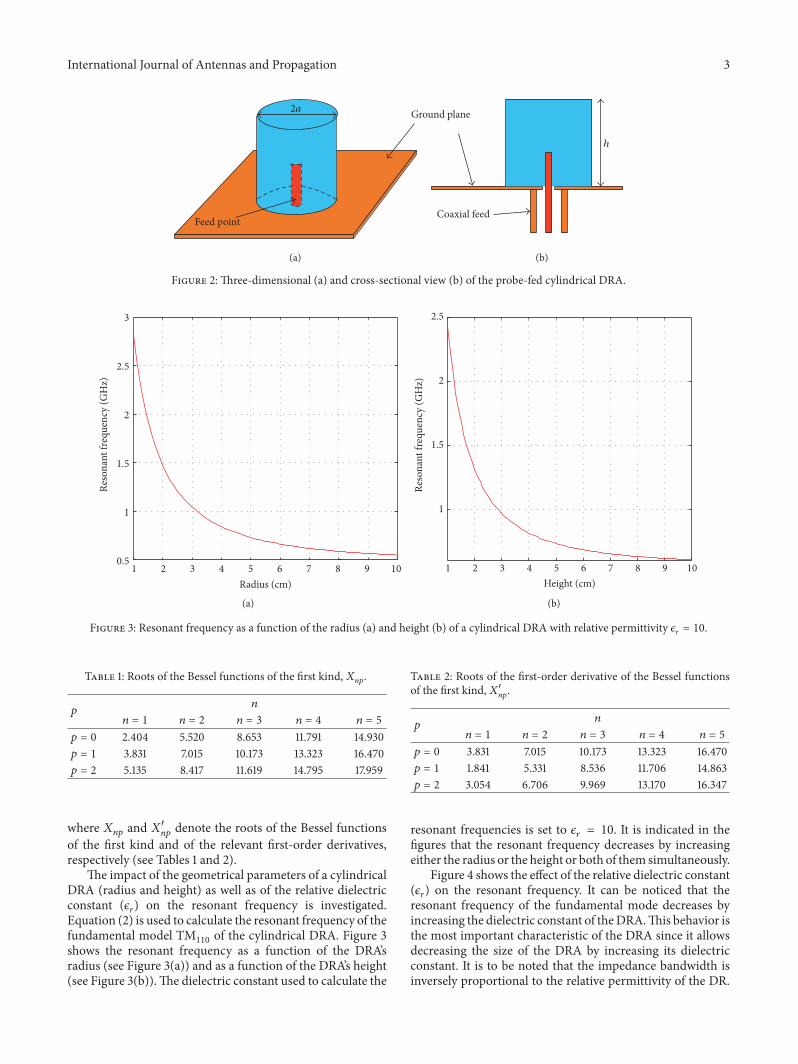
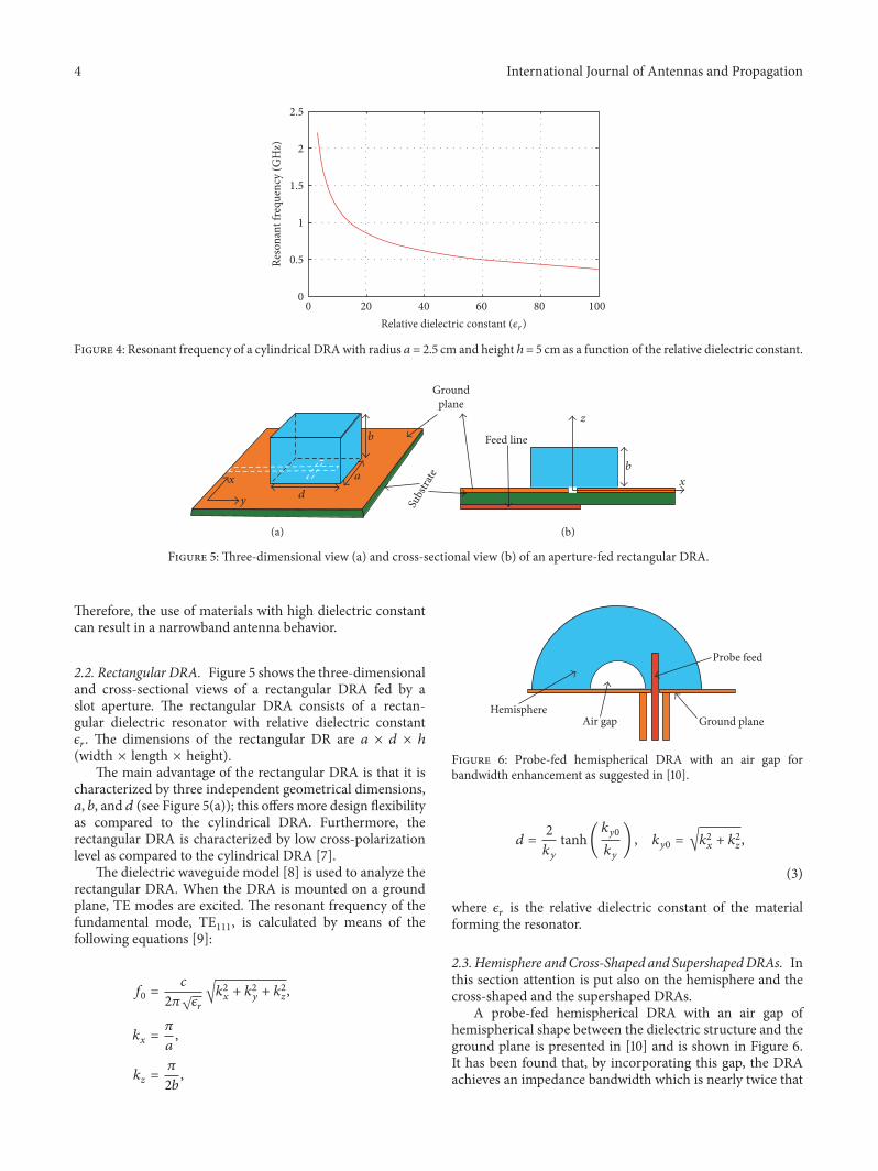
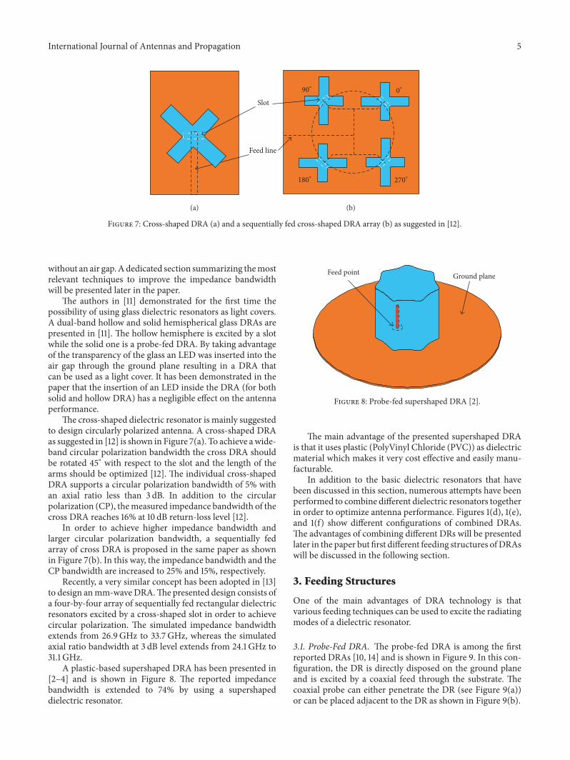
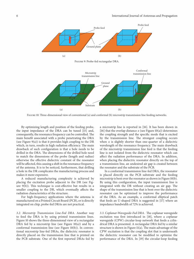
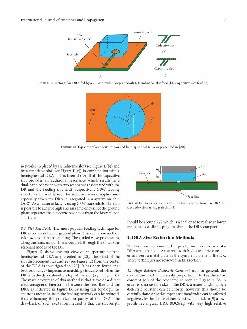
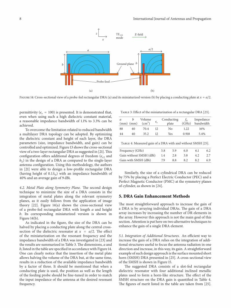
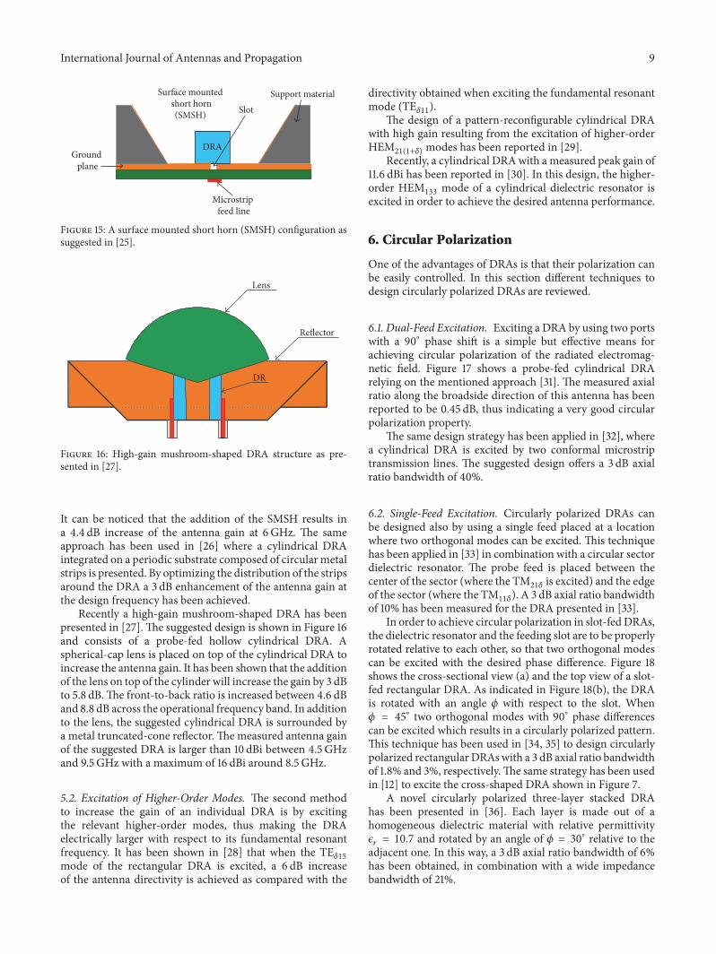
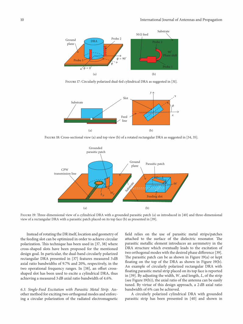
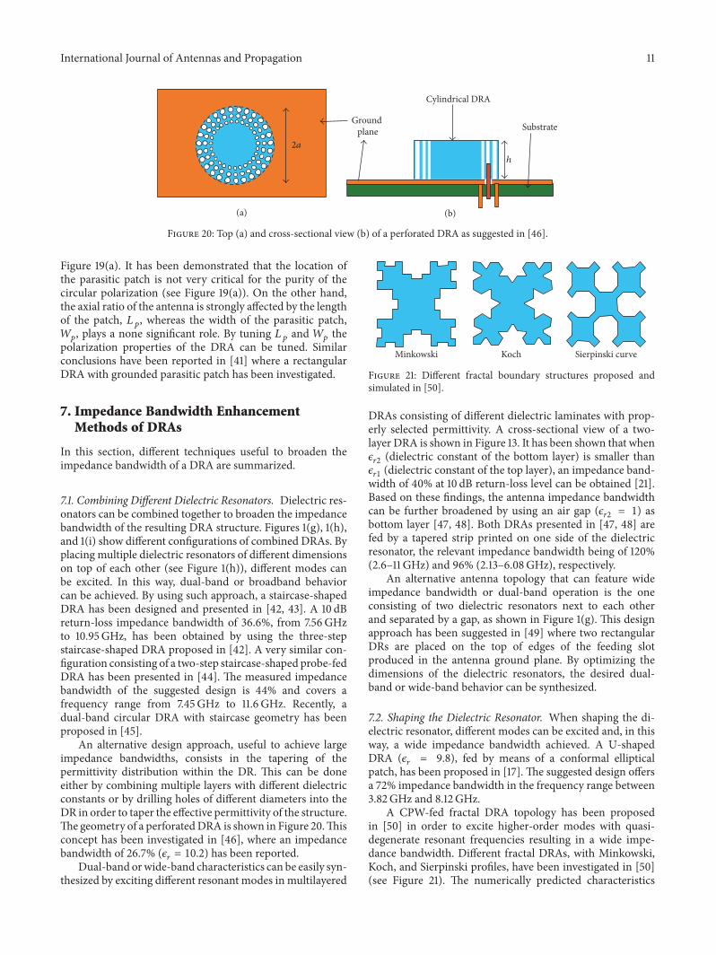
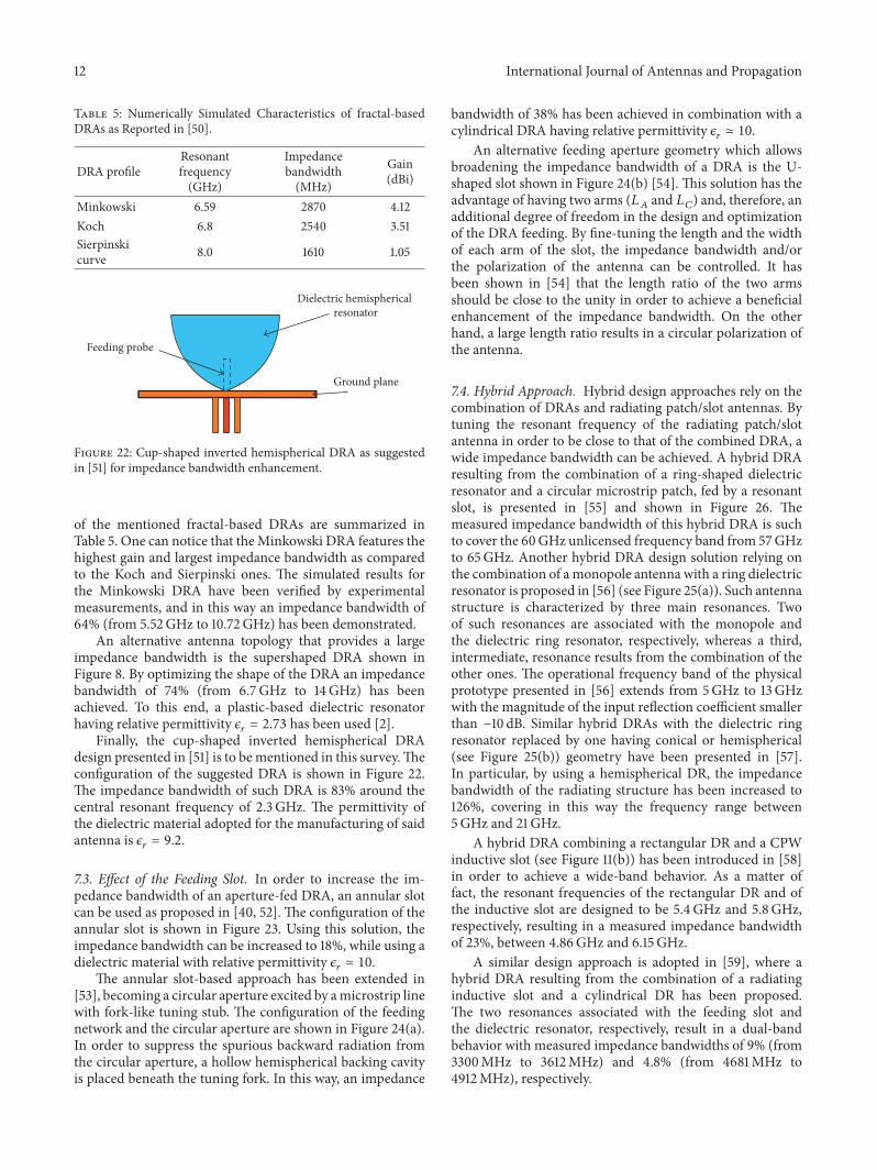
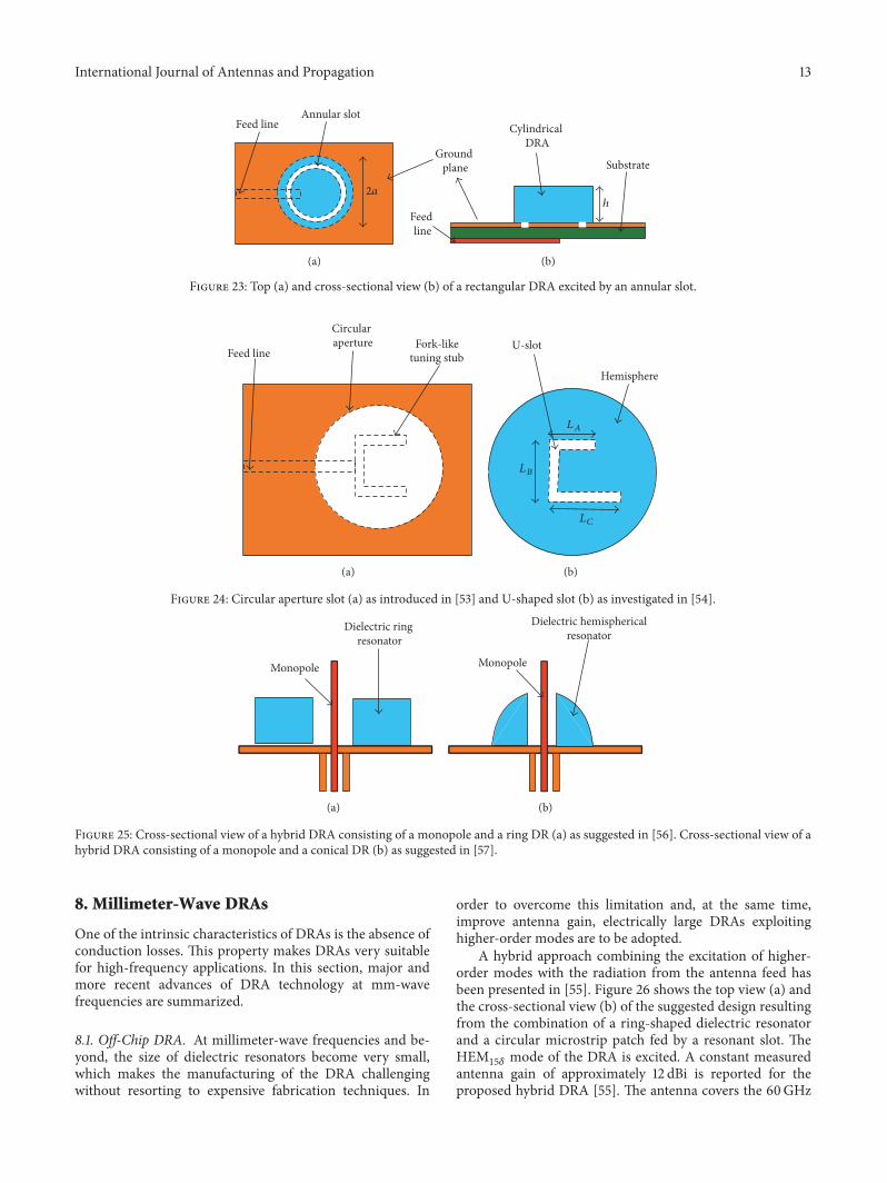
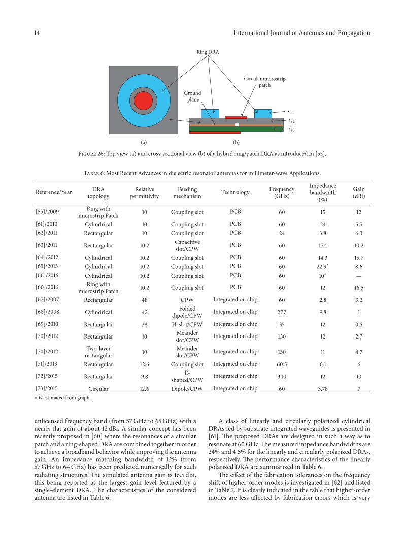
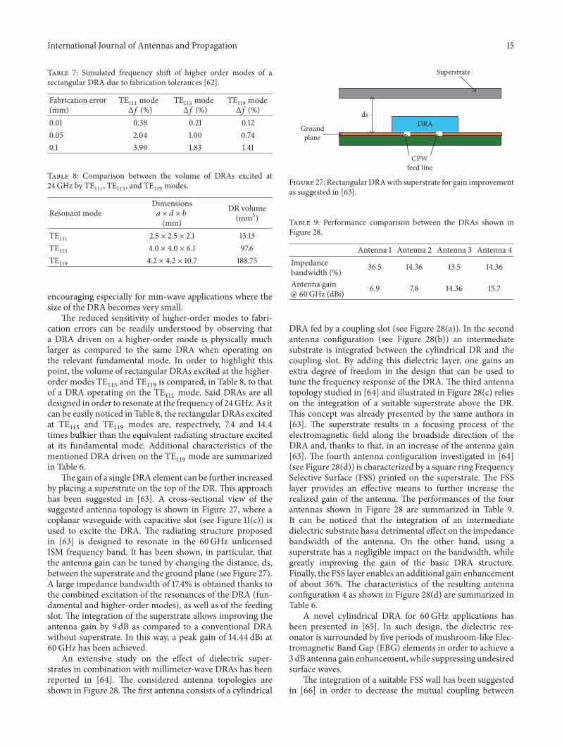
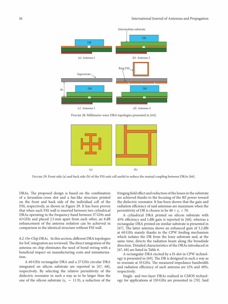
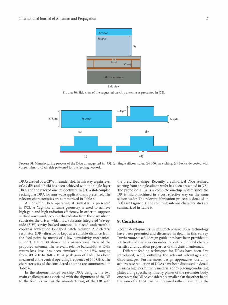

International Journal of
AerospaceEngineeringHindawi Publishing Corporationhttpwwwhindawicom Volume 2014
RoboticsJournal of
Hindawi Publishing Corporationhttpwwwhindawicom Volume 2014
Hindawi Publishing Corporationhttpwwwhindawicom Volume 2014
Active and Passive Electronic Components
Control Scienceand Engineering
Journal of
Hindawi Publishing Corporationhttpwwwhindawicom Volume 2014
International Journal of
RotatingMachinery
Hindawi Publishing Corporationhttpwwwhindawicom Volume 2014
Hindawi Publishing Corporation httpwwwhindawicom
Journal ofEngineeringVolume 2014
Submit your manuscripts athttpwwwhindawicom
VLSI Design
Hindawi Publishing Corporationhttpwwwhindawicom Volume 2014
Hindawi Publishing Corporationhttpwwwhindawicom Volume 2014
Shock and Vibration
Hindawi Publishing Corporationhttpwwwhindawicom Volume 2014
Civil EngineeringAdvances in
Acoustics and VibrationAdvances in
Hindawi Publishing Corporationhttpwwwhindawicom Volume 2014
Hindawi Publishing Corporationhttpwwwhindawicom Volume 2014
Electrical and Computer Engineering
Journal of
Advances inOptoElectronics
Hindawi Publishing Corporation httpwwwhindawicom
Volume 2014
The Scientific World JournalHindawi Publishing Corporation httpwwwhindawicom Volume 2014
SensorsJournal of
Hindawi Publishing Corporationhttpwwwhindawicom Volume 2014
Modelling amp Simulation in EngineeringHindawi Publishing Corporation httpwwwhindawicom Volume 2014
Hindawi Publishing Corporationhttpwwwhindawicom Volume 2014
Chemical EngineeringInternational Journal of Antennas and
Propagation
International Journal of
Hindawi Publishing Corporationhttpwwwhindawicom Volume 2014
Hindawi Publishing Corporationhttpwwwhindawicom Volume 2014
Navigation and Observation
International Journal of
Hindawi Publishing Corporationhttpwwwhindawicom Volume 2014
DistributedSensor Networks
International Journal of