Embed Size (px)
Citation preview
Review ArticleHybrid Adaptive Beaconing in VehicularAd Hoc Networks: A Survey
Safdar Hussain Bouk, Gwanghyeon Kim, Syed Hassan Ahmed, and Dongkyun Kim
School of Computer Science and Engineering, Kyungpook National University, Daegu 702-701, Republic of Korea
Correspondence should be addressed to Dongkyun Kim; [email protected]
Received 26 September 2014; Accepted 19 February 2015
Academic Editor: Athanasios Gkelias
Copyright © 2015 Safdar Hussain Bouk et al. This is an open access article distributed under the Creative Commons AttributionLicense, which permits unrestricted use, distribution, and reproduction in any medium, provided the original work is properlycited.
Beacon or safety messages are broadcasted in vehicular ad hoc networks (VANETs) to disseminate network state or emergencyincident information to other vehicles in the network. The freshness of information depends upon the frequent transmissionof beacons. Similarly, to increase the awareness area or communicating with the distant nodes, beacons are disseminated witha high transmission power. However, increasing the beacon transmission power or rate has a negative effect on informationcommunication efficiency because of the finite bandwidth of the wireless link. Therefore, different schemes have been proposed toindividually control beacon’s transmission power, transmission rate, or contention window at the MAC layer, or any combinationof those, to achieve quality beacon communication in VANETs. The latter case is called hybrid adaptive beaconing schemes.In literature, there are many hybrid adaptive beaconing schemes that control multiple communication parameters to efficientlybroadcast beacon messages in VANETs. In this paper, we explicitly survey and summarized various aspects of those schemes. Theopen and challenging issues are also highlighted in this paper.
1. Introduction
Intelligent transportation system (ITS) is inevitable for thecurrent growth rate in the number of automobiles aroundthe globe. It consists of applications, technology, and com-munication infrastructure to provide mobility managementand traffic management and enables coordination and safetransportation for various users and operators. Main featuresand services of ITS include driver and passengers’ safety,comfort, efficiency, road, and other information availabilityandmanagement on the road.The users and operators of ITSmake decisions based on the real-time data collected fromthe system. The main functions of ITS include collection,distribution or communication, and processing of real-timedata and take decisions independently (e.g., control trafficlight’s duration, vary speed limits, control vehicle’s maneuverautonomously or with little human intervention, etc.) orprovide aid to the operators in transport management. Oneof the widely researched and potential architectures for ITS isthe vehicular ad hoc network (VANET) [1, 2].
VANETmostly provides wireless communication amongvehicles (called vehicle to vehicle or V2V communication)
and between vehicles and the equipment installed at roadside(called vehicle to infrastructure or V2I communication).As vehicles move at the higher speed, therefore, networktopology changes rapidly. Another effect of thismobility is theshort link lifetime and variable network density.Thismakes itchallenging to maintain vehicles’ proximity information withminimum information exchange within the VANET.
Due to ad hoc in nature, VANETs work without relyingon any preestablished network infrastructure. The fast nodesor vehicles mobility on structured roads and streets infras-tructure makes this large size network a highly dynamic.Each vehicle is equipped with wireless technology to coop-eratively exchange or broadcast information with othervehicles in the network. The wireless technologies thathave been investigated in vehicular networks during thepast decade include dedicated short-range communications(DSRC)/wireless access in vehicular environment (WAVE)[3–5], cellular [6], satellite [7], and WiMAX [8].
DSRC/WAVE is exclusively proposed for the vehicularnetworks and it considers IEEE 802.11𝑝 for Physical andMAC layer management and control operations to supportupper layer communication. IEEE 1609 is used to provide
Hindawi Publishing CorporationInternational Journal of Distributed Sensor NetworksVolume 2015, Article ID 390360, 16 pageshttp://dx.doi.org/10.1155/2015/390360
2 International Journal of Distributed Sensor Networks
Dense network area Sparse network area
Dense network area
Incident/event
Sparse network area Sparse network area
Figure 1: Incident based sparse and dense network situation.
security functions and services to MAC, network, andtransport layers. DSRC is the name for 5.9GHz frequencyband (ranging from 5.850 to 5.925GHz) that is dedicatedfor ITS communication and WAVE protocol architectureprovides an operation mode for 802.11 that enabled devicesto operate over DSRC band. DSRC band is divided into 7channels of 10MHz to enable short range communication(typically 300m and maximum 1000m) at high data rate,up to 27Mbps, with transmission power (𝑃tx) that rangesfrom 0 to 28.8 dBm. DSRC/WAVE uses a separate channelfor prioritized control and safety related communication.Thepotential safety and traffic management applications offeredby DSRC include warnings or information for
(i) blind spots and lane changing,(ii) forward collision,(iii) left or right turn assistance,(iv) assistance at intersection,(v) emergency breaking,(vi) emergence vehicle approaching,(vii) real-time road condition,(viii) cargo vehicle safety and clearance,(ix) eToll and eParking, and so forth.
In WAVE/DSRC stack, WAVE Short Message Protocol(WSMP) is a network layer protocol which provides commu-nication services for the priority based short messages, calledBeacons, that aremostly communicated over the control chan-nel (CCH). Dissemination of information through beaconmessage in a VANET is termed as beaconing.The informationinside a beacon may include vehicle’s address, location,speed, direction, event, or other information. These shortmessages are used to satisfy information requirements of thesafety and nonsafety applications. In nonsafety applications,general transport awareness information within the networkis disseminated through beacons. Each vehicle broadcasts
a beacon message within its one hop to keep neighborhoodawareness. In case of any emergency situation or an incident,for example, road blocks, landslide, construction sites, acci-dents, traffic jam, and so forth, similar beaconmessage (safetybeaconmessage)may also be used to disseminate informationabout this specific event to warn drivers; refer to Figure 1.Based on severity of the incident, beacon messages may beassigned priorities and broadcasted accordingly. This typeof beacon communication is used in vehicular networks torealize safety applications. In case of an incident or emergencysituation the vehicle that encounters this event first or thevehicle that is involved in the incident triggers a safety beaconmessage to inform neighboring and the trailing vehiclesabout the incident to apply safety precautions proactively.Timely incident information dissemination to assure safety ofpassengers is the main objective of safety beacon messages.Therefore, the safety beacon message should be dissemi-nated with minimum delay, packet loss, and congestion. Thecongestion and packet loss can be caused by the beaconbroadcast storm, when a large number of vehicles broadcastthe beacon message. This leads to an improper informationdissemination in the network.
Since the same CCH is used by all vehicles, beaconingload may saturate the capacity of the channel. Therefore,channel congestion due to beaconing load should be avoidedto minimize beacon collision and communication delay andimprove channel access fairness and reception rate. Severalbeaconing schemes have been proposed in the literature andare classified into two main categories: periodic and adaptive.
Periodic beacon messages are broadcasted at regularintervals or a constant rate (𝑅tx), usually after every 0.1 s or𝑅tx = 10 beacons/s, with constant transmission power, forexample, 𝑃tx = 20 dBm, to announce the status of vehiclewithin its vicinity [9]. Vehicles collect sufficient neighbor-hood information by broadcasting periodic beacons to satisfyinformation requirements of the VANET applications, espe-cially nonsafety applications. The precision of neighborhoodinformation depends on 𝑅tx of beacon message. However,
International Journal of Distributed Sensor Networks 3
Repetitivesparse and dense network
area
Repetitivesparse and dense network
area
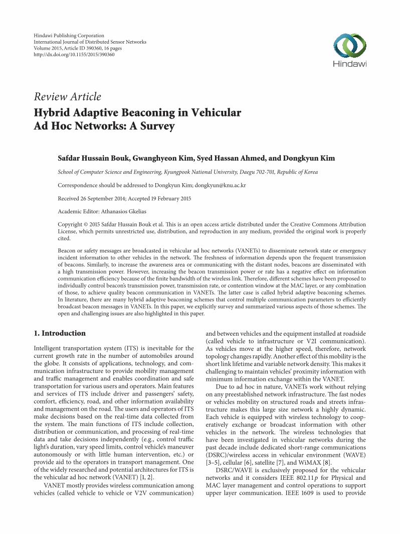
Figure 2: Repetitive sparse and dense network scenario.
the higher beacon 𝑅tx degrades the link performance andresults in beacon loss. On the contrary, low 𝑅tx of a beaconmessage leads to an imprecise neighborhood information atvehicles. This fairness between beacon load and informationprecision is still an open issue. Due to fast mobility of vehiclesin the VANET, network density can abruptly change fromsparse to dense or vice versa; refer to scenario in Figure 2. Incase of a dense network, the periodic broadcast can congestthe channel and consequently increases beacon drop rate andinaccuracy of information at each vehicle in the network [10].
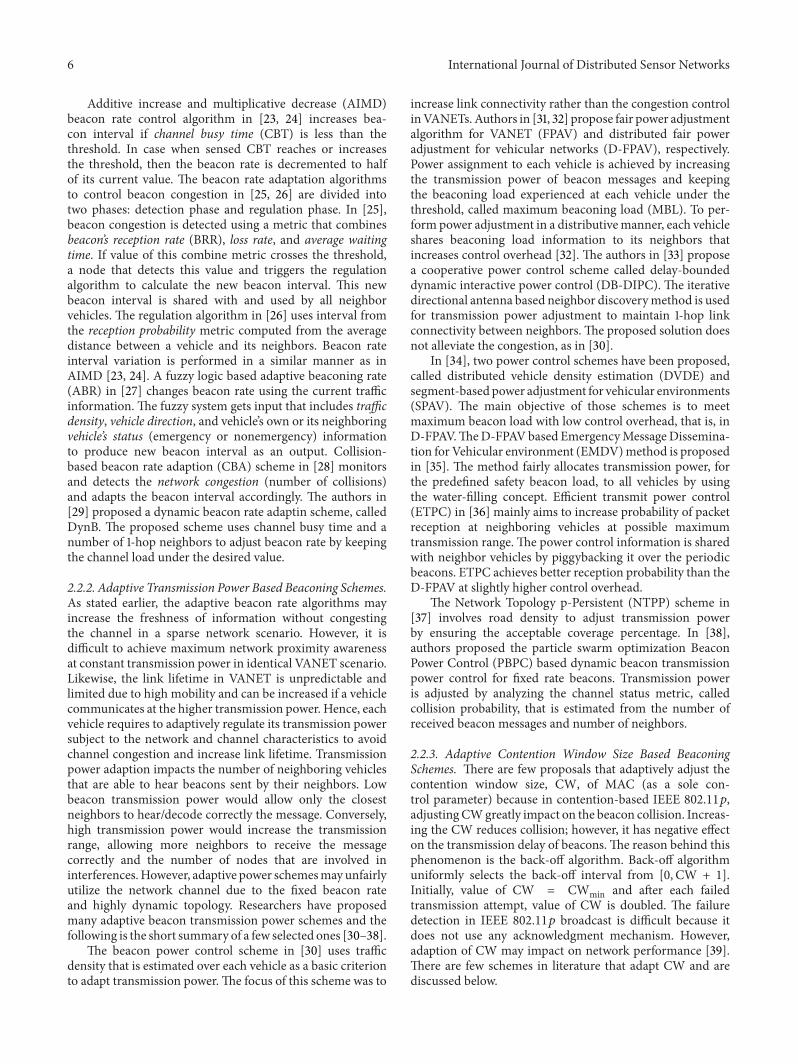
Wireless channel congestion caused by periodic beaconscan be reduced by the adaptive beaconing schemes thatadaptively (a) adjust the beacon transmission rate, calledadaptive beacon rate schemes, (b) regulate transmissionpower to reduce beaconing overhead for sparse and densenetwork conditions, called adaptive beacon power schemes,(c) contention window size (CW) of 802.11𝑝 MAC, termedas adaptive CW schemes, and (d) any combination of theabovementioned schemes, known as hybrid adaptive beacon-ing schemes.
Adaptive beaconing schemes use network conditions,traffic behavior, and/or wireless channel parameters thatinclude a number of neighbors or 1-hope node density,beacon reception probability, beacon reception rate, distancebetween nodes, channel quality, channel busy ratio, andpacket loss rate, to adjust the beacon rate, transmission power,contention window size, or any combination. For example, ifthe number of vehicles in the coverage area of a certain vehicleincreases, then that vehicle increases the beacon interval toavoid congestion of the wireless link. Similarly, the beacontransmission rate is reduced in case of higher beacon lossrate or low beacon reception rate. In case of sparse network,maximum network proximity awareness can be achieved by
increasing the transmission range (𝑇𝑅) of a vehicle. However,
larger transmission range with high network density willoverload the channel. In order to reduce the channel loadin a varying network density environment, adaptive beacontransmission power schemes have been proposed. However,adaptive power schemes may unfairly utilize the networkchannel due to the fixed beacon rate and highly dynamictopology. There are a few proposals that adaptively adjustthe CW ofMAC because, in contention-based IEEE 802.11𝑝,adjusting CW greatly impacts on the beacon collision.Increasing the CW reduces collision rate; however, it has anegative effect on the transmission delay of beacons. Fairnessin channel utilization is achieved by the hybrid adaptiveschemes that adaptively adjust the transmission power, rate,and/or contention windows size of beacon communication.The main objective of these beaconing schemes is to reducebeacon congestion and beacon loss rate and fairly utilizewireless channel to improve information accuracy and datadissemination with minimum delay at every vehicle in thenetwork.
1.1. Motivation. General surveys on beaconing schemes inVANETs have been presented in [11, 12]. However, to thebest of our knowledge, there is no work that provides acomprehensive survey of the hybrid adaptive beaconingschemes for VANETs.Therefore, in this paper, we summarizethe adaptive beaconing schemes with emphasis on the hybridadaptive schemes. These schemes are discussed in termsof network characteristics, simulation environment, andparameters such as VANET scenarios, simulation outcomes,and adaption schemes they employ to dynamically regulatebeacon transmission rate, power, and/or medium access
4 International Journal of Distributed Sensor Networks
Safety applicationsublayer
Non-safety applicationsublayer
Message sublayer SAE J2735
WSMPIEEE 1609.3
LLC sublayerIEEE 802.2
MAC sublayer extension IEEE 1609.4
MAC sublayer
PHY layer IEEE
80
2.11
p
Transport (TCP/UDP)
Network (IPv6)IEEE
160
9.2
secu
rity
Figure 3: WAVE/DSRC communication’s layered architecture.
control (MAC) characteristics for efficient communication ofbeacon messages.
The rest of the paper is structured as follows. First, wegive background information regarding the beacon messageand beaconing schemes in Section 2. Then, Section 3 brieflydiscusses the state of the art hybrid beaconing schemes alongwith the qualitative analysis of parameters and control meth-ods. The comparison of simulation environments used byhybrid adaptive beaconing schemes is presented in Section 4.Section 5 discusses few open and challenging issues. Finally,Section 6 concludes the discussion.
2. Background
This section briefly discusses the background informationrelated to beacon message and beaconing approaches thatefficiently broadcast theses short messages.
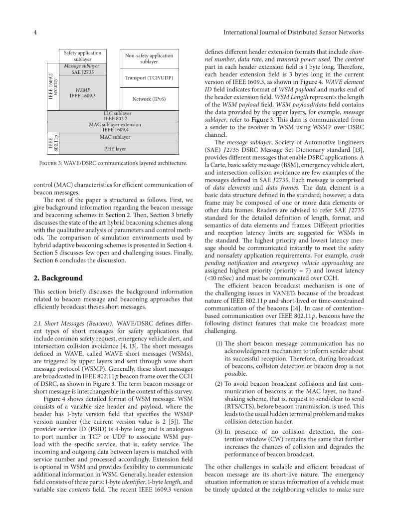
2.1. Short Messages (Beacons). WAVE/DSRC defines differ-ent types of short messages for safety applications thatinclude common safety request, emergency vehicle alert, andintersection collision avoidance [4, 13]. The short messagesdefined in WAVE, called WAVE short messages (WSMs),are triggered by upper layers and sent through wave shortmessage protocol (WSMP). Generally, these short messagesare broadcasted in IEEE 802.11𝑝 beacon frame over the CCHof DSRC, as shown in Figure 3. The term beacon message orshort message is interchangeable in the context of this survey.
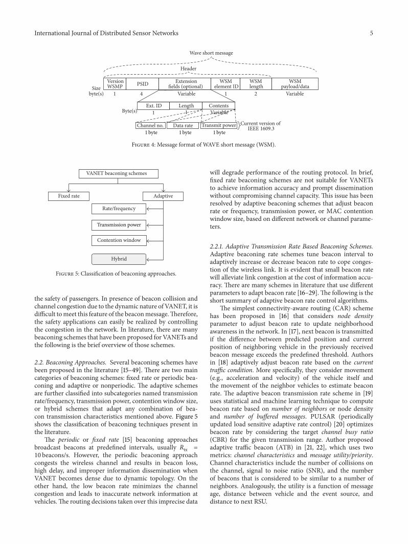
Figure 4 shows detailed format of WSM message. WSMconsists of a variable size header and payload, where theheader has 1-byte version field that specifies the WSMPversion number (the current version value is 2 [5]). Theprovider service ID (PSID) is 4-byte long and is analogousto port number in TCP or UDP to associate WSM pay-load with the specific service, that is, safety service. Theincoming and outgoing data between layers is matched withservice number and processed accordingly. Extension fieldis optional in WSM and provides flexibility to communicateadditional information inWSM. Generally, header extensionfield consists of three parts: 1-byte identifier, 1-byte length, andvariable size contents field. The recent IEEE 1609.3 version
defines different header extension formats that include chan-nel number, data rate, and transmit power used. The contentpart in each header extension field is 1 byte long. Therefore,each header extension field is 3 bytes long in the currentversion of IEEE 1609.3, as shown in Figure 4.WAVE elementID field indicates format of WSM payload and marks end ofthe header extension field.WSMLength represents the lengthof the WSM payload field. WSM payload/data field containsthe data provided by the upper layers, for example, messagesublayer, refer to Figure 3. This data is communicated froma sender to the receiver in WSM using WSMP over DSRCchannel.
The message sublayer, Society of Automotive Engineers(SAE) 𝐽2735 DSRC Message Set Dictionary standard [13],provides different messages that enable DSRC applications. Ala Carte, basic safetymessage (BSM), emergency vehicle alert,and intersection collision avoidance are few examples of themessages defined in SAE 𝐽2735. Each message is comprisedof data elements and data frames. The data element is abasic data structure defined in the standard; however, a dataframe may be composed of one or more data elements orother data frames. Readers are advised to refer SAE 𝐽2735standard for the detailed definition of length, format, andsemantics of data elements and frames. Different prioritiesand reception latency limits are suggested for WSMs inthe standard. The highest priority and lowest latency mes-sage should be communicated instantly to meet the safetyand nonsafety application requirements. For example, crashpending notification and emergency vehicle approaching areassigned highest priority (priority = 7) and lowest latency(<10mSec) and must be communicated over CCH.
The efficient beacon broadcast mechanism is one ofthe challenging issues in VANETs because of the broadcastnature of IEEE 802.11𝑝 and short-lived or time-constrainedcommunication of the beacons [14]. In case of contention-based communication over IEEE 802.11𝑝, beacons have thefollowing distinct features that make the broadcast morechallenging.
(1) The short beacon message communication has noacknowledgment mechanism to inform sender aboutits successful reception. Therefore, during broadcastof beacons, collision detection or beacon drop is notpossible.
(2) To avoid beacon broadcast collisions and fast com-munication of beacons at the MAC layer, no hand-shaking scheme, that is, request to send/clear to send(RTS/CTS), before beacon transmission, is used.Thisleads to the usual hidden terminal problemandmakescollision detection harder.
(3) In presence of no collision detection, the con-tention window (CW) remains the same that furtherincreases the chances of collision and degrades theperformance of beacon broadcast.
The other challenges in scalable and efficient broadcast ofbeacon message are its short-live nature. The emergencysituation information or status information of a vehicle mustbe timely updated at the neighboring vehicles to make sure
International Journal of Distributed Sensor Networks 5
VersionWSMP PSID Extension
fields (optional) WSM
element IDWSM length
WSMpayload/dataSize
byte(s) 1 4 Variable Variable1 2
Header
Ext. ID Length ContentsByte(s) 1 1 Variable
Wave short message
Channel no. Data rate Transmit power Current version of IEEE 1609.3
1byte 1byte1byte
Figure 4: Message format of WAVE short message (WSM).
VANET beaconing schemes
Fixed rate Adaptive
Rate/frequency
Contention window
Hybrid
Transmission power
Figure 5: Classification of beaconing approaches.
the safety of passengers. In presence of beacon collision andchannel congestion due to the dynamic nature of VANET, it isdifficult tomeet this feature of the beaconmessage.Therefore,the safety applications can easily be realized by controllingthe congestion in the network. In literature, there are manybeaconing schemes that have been proposed for VANETs andthe following is the brief overview of those schemes.
2.2. Beaconing Approaches. Several beaconing schemes havebeen proposed in the literature [15–49]. There are two maincategories of beaconing schemes: fixed rate or periodic bea-coning and adaptive or nonperiodic. The adaptive schemesare further classified into subcategories named transmissionrate/frequency, transmission power, contention window size,or hybrid schemes that adapt any combination of bea-con transmission characteristics mentioned above. Figure 5shows the classification of beaconing techniques present inthe literature.
The periodic or fixed rate [15] beaconing approachesbroadcast beacons at predefined intervals, usually 𝑅tx =
10 beacons/s. However, the periodic beaconing approachcongests the wireless channel and results in beacon loss,high delay, and improper information dissemination whenVANET becomes dense due to dynamic topology. On theother hand, the low beacon rate minimizes the channelcongestion and leads to inaccurate network information atvehicles.The routing decisions taken over this imprecise data
will degrade performance of the routing protocol. In brief,fixed rate beaconing schemes are not suitable for VANETsto achieve information accuracy and prompt disseminationwithout compromising channel capacity. This issue has beenresolved by adaptive beaconing schemes that adjust beaconrate or frequency, transmission power, or MAC contentionwindow size, based on different network or channel parame-ters.
2.2.1. Adaptive Transmission Rate Based Beaconing Schemes.Adaptive beaconing rate schemes tune beacon interval toadaptively increase or decrease beacon rate to cope conges-tion of the wireless link. It is evident that small beacon ratewill alleviate link congestion at the cost of information accu-racy. There are many schemes in literature that use differentparameters to adapt beacon rate [16–29]. The following is theshort summary of adaptive beacon rate control algorithms.
The simplest connectivity-aware routing (CAR) schemehas been proposed in [16] that considers node densityparameter to adjust beacon rate to update neighborhoodawareness in the network. In [17], next beacon is transmittedif the difference between predicted position and currentposition of neighboring vehicle in the previously receivedbeacon message exceeds the predefined threshold. Authorsin [18] adaptively adjust beacon rate based on the currenttraffic condition. More specifically, they consider movement(e.g., acceleration and velocity) of the vehicle itself andthe movement of the neighbor vehicles to estimate beaconrate. The adaptive beacon transmission rate scheme in [19]uses statistical and machine learning technique to computebeacon rate based on number of neighbors or node densityand number of buffered messages. PULSAR (periodicallyupdated load sensitive adaptive rate control) [20] optimizesbeacon rate by considering the target channel busy ratio(CBR) for the given transmission range. Author proposedadaptive traffic beacon (ATB) in [21, 22], which uses twometrics: channel characteristics and message utility/priority.Channel characteristics include the number of collisions onthe channel, signal to noise ratio (SNR), and the numberof beacons that is considered to be similar to a number ofneighbors. Analogously, the utility is a function of messageage, distance between vehicle and the event source, anddistance to next RSU.
6 International Journal of Distributed Sensor Networks
Additive increase and multiplicative decrease (AIMD)beacon rate control algorithm in [23, 24] increases bea-con interval if channel busy time (CBT) is less than thethreshold. In case when sensed CBT reaches or increasesthe threshold, then the beacon rate is decremented to halfof its current value. The beacon rate adaptation algorithmsto control beacon congestion in [25, 26] are divided intotwo phases: detection phase and regulation phase. In [25],beacon congestion is detected using a metric that combinesbeacon’s reception rate (BRR), loss rate, and average waitingtime. If value of this combine metric crosses the threshold,a node that detects this value and triggers the regulationalgorithm to calculate the new beacon interval. This newbeacon interval is shared with and used by all neighborvehicles. The regulation algorithm in [26] uses interval fromthe reception probability metric computed from the averagedistance between a vehicle and its neighbors. Beacon rateinterval variation is performed in a similar manner as inAIMD [23, 24]. A fuzzy logic based adaptive beaconing rate(ABR) in [27] changes beacon rate using the current trafficinformation. The fuzzy system gets input that includes trafficdensity, vehicle direction, and vehicle’s own or its neighboringvehicle’s status (emergency or nonemergency) informationto produce new beacon interval as an output. Collision-based beacon rate adaption (CBA) scheme in [28] monitorsand detects the network congestion (number of collisions)and adapts the beacon interval accordingly. The authors in[29] proposed a dynamic beacon rate adaptin scheme, calledDynB. The proposed scheme uses channel busy time and anumber of 1-hop neighbors to adjust beacon rate by keepingthe channel load under the desired value.
2.2.2. Adaptive Transmission Power Based Beaconing Schemes.As stated earlier, the adaptive beacon rate algorithms mayincrease the freshness of information without congestingthe channel in a sparse network scenario. However, it isdifficult to achieve maximum network proximity awarenessat constant transmission power in identical VANET scenario.Likewise, the link lifetime in VANET is unpredictable andlimited due to high mobility and can be increased if a vehiclecommunicates at the higher transmission power. Hence, eachvehicle requires to adaptively regulate its transmission powersubject to the network and channel characteristics to avoidchannel congestion and increase link lifetime. Transmissionpower adaption impacts the number of neighboring vehiclesthat are able to hear beacons sent by their neighbors. Lowbeacon transmission power would allow only the closestneighbors to hear/decode correctly the message. Conversely,high transmission power would increase the transmissionrange, allowing more neighbors to receive the messagecorrectly and the number of nodes that are involved ininterferences.However, adaptive power schemesmayunfairlyutilize the network channel due to the fixed beacon rateand highly dynamic topology. Researchers have proposedmany adaptive beacon transmission power schemes and thefollowing is the short summary of a few selected ones [30–38].
The beacon power control scheme in [30] uses trafficdensity that is estimated over each vehicle as a basic criterionto adapt transmission power.The focus of this scheme was to
increase link connectivity rather than the congestion controlinVANETs.Authors in [31, 32] propose fair power adjustmentalgorithm for VANET (FPAV) and distributed fair poweradjustment for vehicular networks (D-FPAV), respectively.Power assignment to each vehicle is achieved by increasingthe transmission power of beacon messages and keepingthe beaconing load experienced at each vehicle under thethreshold, called maximum beaconing load (MBL). To per-form power adjustment in a distributivemanner, each vehicleshares beaconing load information to its neighbors thatincreases control overhead [32]. The authors in [33] proposea cooperative power control scheme called delay-boundeddynamic interactive power control (DB-DIPC). The iterativedirectional antenna based neighbor discoverymethod is usedfor transmission power adjustment to maintain 1-hop linkconnectivity between neighbors. The proposed solution doesnot alleviate the congestion, as in [30].
In [34], two power control schemes have been proposed,called distributed vehicle density estimation (DVDE) andsegment-based power adjustment for vehicular environments(SPAV). The main objective of those schemes is to meetmaximum beacon load with low control overhead, that is, inD-FPAV.TheD-FPAVbased EmergencyMessageDissemina-tion for Vehicular environment (EMDV)method is proposedin [35]. The method fairly allocates transmission power, forthe predefined safety beacon load, to all vehicles by usingthe water-filling concept. Efficient transmit power control(ETPC) in [36] mainly aims to increase probability of packetreception at neighboring vehicles at possible maximumtransmission range. The power control information is sharedwith neighbor vehicles by piggybacking it over the periodicbeacons. ETPC achieves better reception probability than theD-FPAV at slightly higher control overhead.
The Network Topology p-Persistent (NTPP) scheme in[37] involves road density to adjust transmission powerby ensuring the acceptable coverage percentage. In [38],authors proposed the particle swarm optimization BeaconPower Control (PBPC) based dynamic beacon transmissionpower control for fixed rate beacons. Transmission poweris adjusted by analyzing the channel status metric, calledcollision probability, that is estimated from the number ofreceived beacon messages and number of neighbors.
2.2.3. Adaptive Contention Window Size Based BeaconingSchemes. There are few proposals that adaptively adjust thecontention window size, CW, of MAC (as a sole con-trol parameter) because in contention-based IEEE 802.11𝑝,adjustingCWgreatly impact on the beacon collision. Increas-ing the CW reduces collision; however, it has negative effecton the transmission delay of beacons. The reason behind thisphenomenon is the back-off algorithm. Back-off algorithmuniformly selects the back-off interval from [0,CW + 1].Initially, value of CW = CWmin and after each failedtransmission attempt, value of CW is doubled. The failuredetection in IEEE 802.11𝑝 broadcast is difficult because itdoes not use any acknowledgment mechanism. However,adaption of CW may impact on network performance [39].There are few schemes in literature that adapt CW and arediscussed below.
International Journal of Distributed Sensor Networks 7
The authors in [40] proposed centralized and distributedadaptive CW update mechanism. The centralized adaptiveCW algorithm takes into account the number of concurrenttransmitting vehicles, packet size, length ofDIFS, and optimaltransmission probability, to compute a new value of CW.On the other hand, distributed adaptive CW algorithm usesproportion of busy channel time to set new value of CW.Thebusy channel time is the count of time a channel is observedbusy during observation interval. If the difference betweencurrent and previous channel busy time proportion is higherthan the threshold, then CW is updated.
The architecture in [41] adaptively configures the MACand network-layer parameters. The proposed approachadjusts MAC layer and beaconing characteristics to optimalvalues for VANETs. However, the authors did not considerthe dynamic density characteristics of VANET, that is, vehicledensity fluctuation between sparse and dense, to estimatethe parameters. The adaptive CW based scheme in [42]uses 1-hop neighbor density parameter, number of vehiclesheard during time 𝑡 and 𝜆 to estimate new CW value, where𝜆 is derived by authors through simulations. Numeroussimulations had been performed to ascertain associationamong CW, node density, and number of hidden nodes. Itis concluded that the adaption of CW can improve receptionprobability and network performance; however, there are nosimulations in [42] to support this statement.
The above discussed schemes adaptively regulate oneparameter of VANET that includes transmission rate, power,or contention window of MAC layer and keep other param-eters constant. For example, transmission rate adaptiveschemes use constant transmission power and CW. Similarly,adaptive transmission power schemes keep constant trans-mission rate and CW. In result, these schemes just eitherfairly utilize link, reduce delay, increase link connectivity, ornetwork proximity, and so forth. However, these schemes failto target the key challenges of VANETs at once. Therefore,authors have proposed schemes that efficiently utilize theavailable bandwidthwhen there is (i) a short link connectivitytime due to the rapidly changing road environment and(ii) bandwidth congestion due to continuous collection anddissemination of data. This category of beaconing schemesis called hybrid adaptive beaconing or hybrid beaconingschemes, which are point of focus in this survey. Hybridadaptive beaconing strategies accomplish fairness in channelutilization by adaptively adjusting the beacon rate, trans-mission power, and/or CW. The main objective of thesebeaconing schemes is to reduce beacon congestion andbeacon loss rate and fairly utilize wireless channel to improveinformation accuracy and data disseminationwithminimumdelay at every vehicle in the network. The importance ofhybrid adaptive beaconing schemes convinced us to providereaders a very comprehensive survey of stat of the art hybridadaptive beaconing schemes that is given next section.
3. Hybrid Adaptive Beaconing Schemes
In this section, we briefly discuss the hybrid adaptive bea-coning schemes that jointly adapt transmission power 𝑃tx,beacon rate 𝑅tx, and/or contention window size CW. The
default values of CW[AC]
Estimate local vehicle density “K”
Inc. CW[AC]
Dec. CW[AC]
Maintain current CW[AC]
(1)
Estimate collision rate
Transmission power adaption
Messages received?
orhighest priority
message?
Estimated collision rate
Estimated collision rate
CW size adaption
Joint adaption start
No
Yes
Yes
No
Yes
No
No
Yes
Joint adaption stop
TR = R
Compute TR as
K < 𝜏1
≥ 𝜏2
< 𝜏2
Map TR to Ptx
R: maximum transmission range𝛼: traffic constant𝜏1: vehicle density threshold𝜏2: beacon collision rate thresholdPtx : transmission power in dBm
Figure 6: Joint adaption of 𝑃tx and CW [44].
discussion includes beacon congestion control parameters,congestion control method, and performance parametersthat are evaluated in those schemes through simulations.
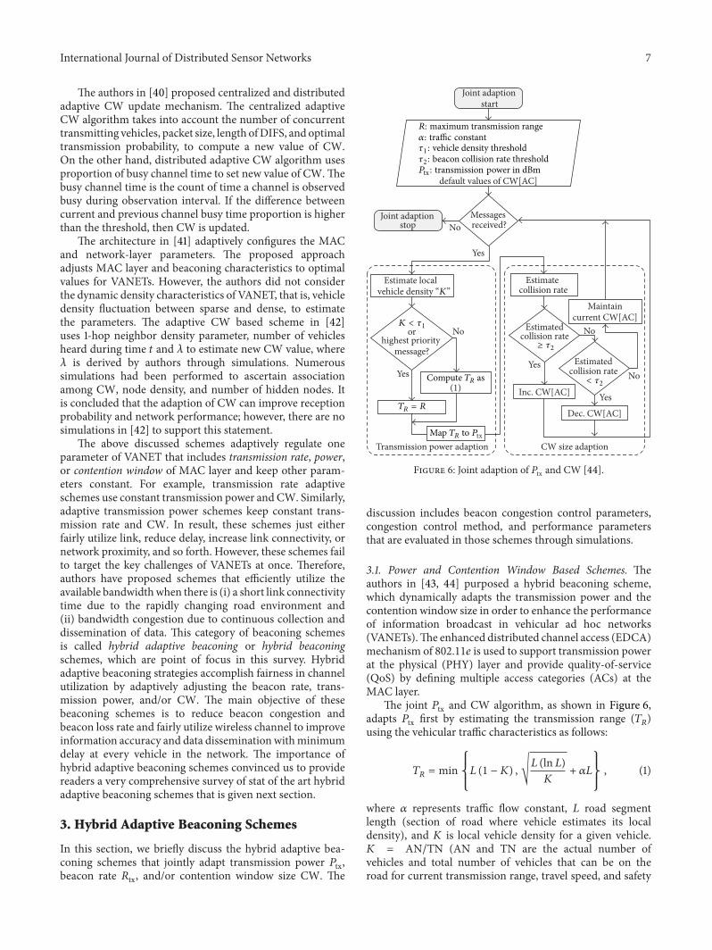
3.1. Power and Contention Window Based Schemes. Theauthors in [43, 44] purposed a hybrid beaconing scheme,which dynamically adapts the transmission power and thecontention window size in order to enhance the performanceof information broadcast in vehicular ad hoc networks(VANETs).The enhanced distributed channel access (EDCA)mechanism of 802.11𝑒 is used to support transmission powerat the physical (PHY) layer and provide quality-of-service(QoS) by defining multiple access categories (ACs) at theMAC layer.
The joint 𝑃tx and CW algorithm, as shown in Figure 6,adapts 𝑃tx first by estimating the transmission range (𝑇
𝑅)
using the vehicular traffic characteristics as follows:
𝑇𝑅= min
{
{
{
𝐿 (1 − 𝐾) ,√𝐿 (ln 𝐿)𝐾
+ 𝛼𝐿
}
}
}
, (1)
where 𝛼 represents traffic flow constant, 𝐿 road segmentlength (section of road where vehicle estimates its localdensity), and 𝐾 is local vehicle density for a given vehicle.𝐾 = AN/TN (AN and TN are the actual number ofvehicles and total number of vehicles that can be on theroad for current transmission range, travel speed, and safety
8 International Journal of Distributed Sensor Networks
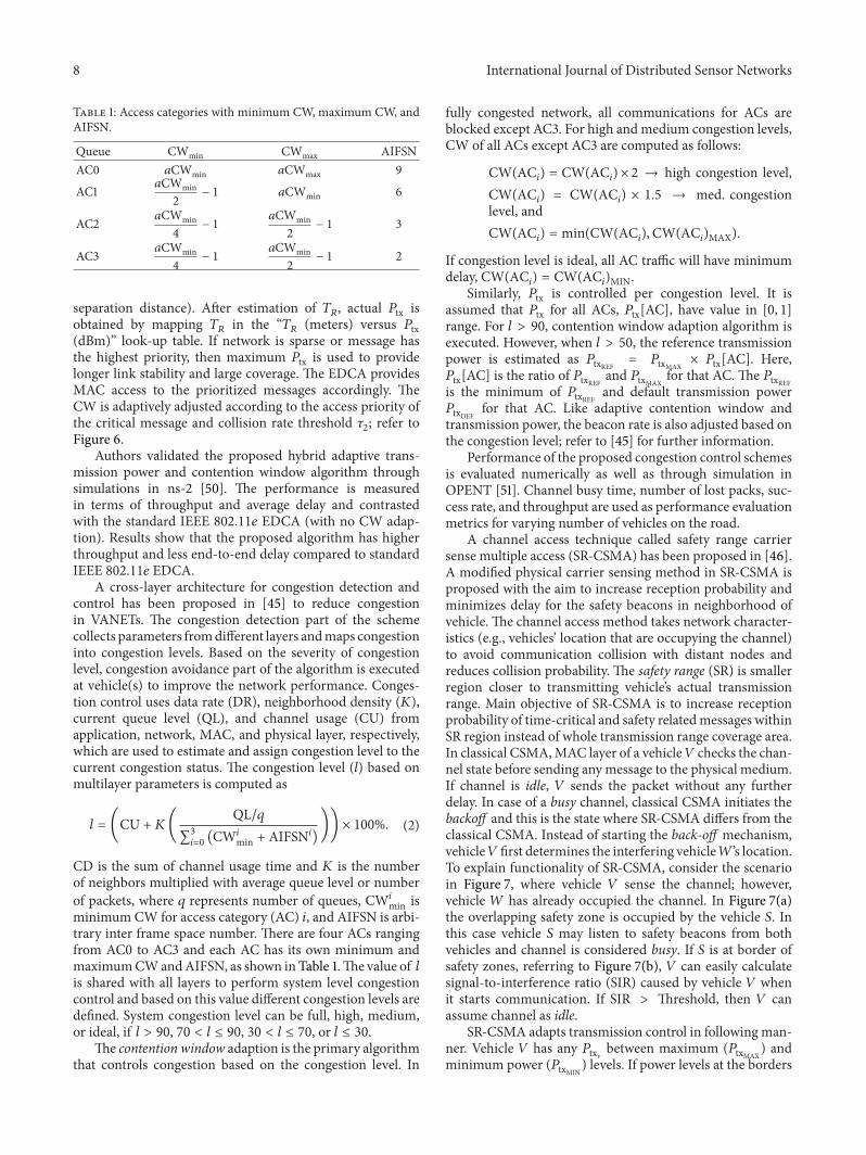
Table 1: Access categories with minimum CW, maximum CW, andAIFSN.
Queue CWmin CWmax AIFSNAC0 𝑎CWmin 𝑎CWmax 9
AC1 𝑎CWmin2
− 1 𝑎CWmin 6
AC2 𝑎CWmin4
− 1𝑎CWmin2
− 1 3
AC3 𝑎CWmin4
− 1𝑎CWmin2
− 1 2
separation distance). After estimation of 𝑇𝑅, actual 𝑃tx is
obtained by mapping 𝑇𝑅in the “𝑇
𝑅(meters) versus 𝑃tx
(dBm)” look-up table. If network is sparse or message hasthe highest priority, then maximum 𝑃tx is used to providelonger link stability and large coverage. The EDCA providesMAC access to the prioritized messages accordingly. TheCW is adaptively adjusted according to the access priority ofthe critical message and collision rate threshold 𝜏
2; refer to
Figure 6.Authors validated the proposed hybrid adaptive trans-
mission power and contention window algorithm throughsimulations in ns-2 [50]. The performance is measuredin terms of throughput and average delay and contrastedwith the standard IEEE 802.11𝑒 EDCA (with no CW adap-tion). Results show that the proposed algorithm has higherthroughput and less end-to-end delay compared to standardIEEE 802.11𝑒 EDCA.
A cross-layer architecture for congestion detection andcontrol has been proposed in [45] to reduce congestionin VANETs. The congestion detection part of the schemecollects parameters fromdifferent layers andmaps congestioninto congestion levels. Based on the severity of congestionlevel, congestion avoidance part of the algorithm is executedat vehicle(s) to improve the network performance. Conges-tion control uses data rate (DR), neighborhood density (𝐾),current queue level (QL), and channel usage (CU) fromapplication, network, MAC, and physical layer, respectively,which are used to estimate and assign congestion level to thecurrent congestion status. The congestion level (𝑙) based onmultilayer parameters is computed as
𝑙 = (CU + 𝐾(QL/𝑞
∑3
𝑖=0(CW𝑖min + AIFSN𝑖)
)) × 100%. (2)
CD is the sum of channel usage time and 𝐾 is the numberof neighbors multiplied with average queue level or numberof packets, where 𝑞 represents number of queues, CW𝑖min isminimum CW for access category (AC) 𝑖, and AIFSN is arbi-trary inter frame space number. There are four ACs rangingfrom AC0 to AC3 and each AC has its own minimum andmaximumCWandAIFSN, as shown in Table 1.The value of 𝑙is shared with all layers to perform system level congestioncontrol and based on this value different congestion levels aredefined. System congestion level can be full, high, medium,or ideal, if 𝑙 > 90, 70 < 𝑙 ≤ 90, 30 < 𝑙 ≤ 70, or 𝑙 ≤ 30.
The contention window adaption is the primary algorithmthat controls congestion based on the congestion level. In
fully congested network, all communications for ACs areblocked except AC3. For high andmedium congestion levels,CW of all ACs except AC3 are computed as follows:
CW(AC𝑖) = CW(AC
𝑖) × 2 → high congestion level,
CW(AC𝑖) = CW(AC
𝑖) × 1.5 → med. congestion
level, andCW(AC
𝑖) = min(CW(AC
𝑖),CW(AC
𝑖)MAX).
If congestion level is ideal, all AC traffic will have minimumdelay, CW(AC
𝑖) = CW(AC
𝑖)MIN.
Similarly, 𝑃tx is controlled per congestion level. It isassumed that 𝑃tx for all ACs, 𝑃tx[AC], have value in [0, 1]range. For 𝑙 > 90, contention window adaption algorithm isexecuted. However, when 𝑙 > 50, the reference transmissionpower is estimated as 𝑃txREF = 𝑃txMAX
× 𝑃tx[AC]. Here,𝑃tx[AC] is the ratio of 𝑃txREF and 𝑃txMAX
for that AC. The 𝑃txREFis the minimum of 𝑃txREF and default transmission power𝑃txDEF for that AC. Like adaptive contention window andtransmission power, the beacon rate is also adjusted based onthe congestion level; refer to [45] for further information.
Performance of the proposed congestion control schemesis evaluated numerically as well as through simulation inOPENT [51]. Channel busy time, number of lost packs, suc-cess rate, and throughput are used as performance evaluationmetrics for varying number of vehicles on the road.
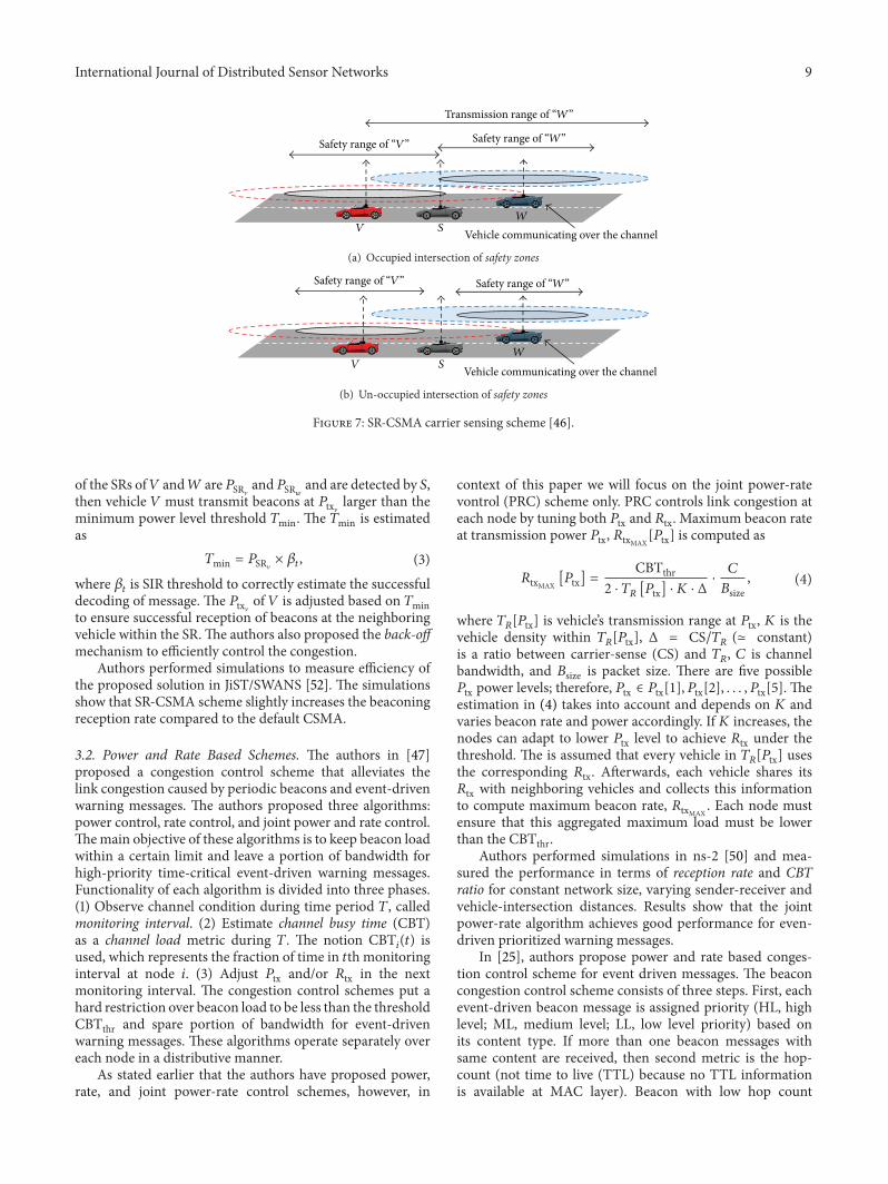
A channel access technique called safety range carriersense multiple access (SR-CSMA) has been proposed in [46].A modified physical carrier sensing method in SR-CSMA isproposed with the aim to increase reception probability andminimizes delay for the safety beacons in neighborhood ofvehicle. The channel access method takes network character-istics (e.g., vehicles’ location that are occupying the channel)to avoid communication collision with distant nodes andreduces collision probability. The safety range (SR) is smallerregion closer to transmitting vehicle’s actual transmissionrange. Main objective of SR-CSMA is to increase receptionprobability of time-critical and safety relatedmessages withinSR region instead of whole transmission range coverage area.In classical CSMA,MAC layer of a vehicle𝑉 checks the chan-nel state before sending any message to the physical medium.If channel is idle, 𝑉 sends the packet without any furtherdelay. In case of a busy channel, classical CSMA initiates thebackoff and this is the state where SR-CSMA differs from theclassical CSMA. Instead of starting the back-off mechanism,vehicle𝑉 first determines the interfering vehicle𝑊’s location.To explain functionality of SR-CSMA, consider the scenarioin Figure 7, where vehicle 𝑉 sense the channel; however,vehicle 𝑊 has already occupied the channel. In Figure 7(a)the overlapping safety zone is occupied by the vehicle 𝑆. Inthis case vehicle 𝑆 may listen to safety beacons from bothvehicles and channel is considered busy. If 𝑆 is at border ofsafety zones, referring to Figure 7(b), 𝑉 can easily calculatesignal-to-interference ratio (SIR) caused by vehicle 𝑉 whenit starts communication. If SIR > Threshold, then 𝑉 canassume channel as idle.
SR-CSMA adapts transmission control in following man-ner. Vehicle 𝑉 has any 𝑃txV between maximum (𝑃txMAX
) andminimum power (𝑃txMIN
) levels. If power levels at the borders
International Journal of Distributed Sensor Networks 9
VW
S
Safety range of “W”Safety range of “V”
Transmission range of “W”
Vehicle communicating over the channel
(a) Occupied intersection of safety zones
VW
S Vehicle communicating over the channel
Safety range of “W”Safety range of “V”
(b) Un-occupied intersection of safety zones
Figure 7: SR-CSMA carrier sensing scheme [46].
of the SRs of𝑉 and𝑊 are 𝑃SRVand 𝑃SR
𝑤
and are detected by 𝑆,then vehicle 𝑉 must transmit beacons at 𝑃txV larger than theminimum power level threshold 𝑇min. The 𝑇min is estimatedas
𝑇min = 𝑃SRV× 𝛽𝑡, (3)
where 𝛽𝑡is SIR threshold to correctly estimate the successful
decoding of message. The 𝑃txV of 𝑉 is adjusted based on 𝑇minto ensure successful reception of beacons at the neighboringvehicle within the SR.The authors also proposed the back-offmechanism to efficiently control the congestion.
Authors performed simulations to measure efficiency ofthe proposed solution in JiST/SWANS [52]. The simulationsshow that SR-CSMA scheme slightly increases the beaconingreception rate compared to the default CSMA.
3.2. Power and Rate Based Schemes. The authors in [47]proposed a congestion control scheme that alleviates thelink congestion caused by periodic beacons and event-drivenwarning messages. The authors proposed three algorithms:power control, rate control, and joint power and rate control.Themain objective of these algorithms is to keep beacon loadwithin a certain limit and leave a portion of bandwidth forhigh-priority time-critical event-driven warning messages.Functionality of each algorithm is divided into three phases.(1) Observe channel condition during time period 𝑇, calledmonitoring interval. (2) Estimate channel busy time (CBT)as a channel load metric during 𝑇. The notion CBT
𝑖(𝑡) is
used, which represents the fraction of time in 𝑡th monitoringinterval at node 𝑖. (3) Adjust 𝑃tx and/or 𝑅tx in the nextmonitoring interval. The congestion control schemes put ahard restriction over beacon load to be less than the thresholdCBTthr and spare portion of bandwidth for event-drivenwarning messages. These algorithms operate separately overeach node in a distributive manner.
As stated earlier that the authors have proposed power,rate, and joint power-rate control schemes, however, in
context of this paper we will focus on the joint power-ratevontrol (PRC) scheme only. PRC controls link congestion ateach node by tuning both 𝑃tx and 𝑅tx. Maximum beacon rateat transmission power 𝑃tx, 𝑅txMAX
[𝑃tx] is computed as
𝑅txMAX[𝑃tx] =
CBTthr2 ⋅ 𝑇𝑅[𝑃tx] ⋅ 𝐾 ⋅ Δ
⋅𝐶
𝐵size, (4)
where 𝑇𝑅[𝑃tx] is vehicle’s transmission range at 𝑃tx, 𝐾 is the
vehicle density within 𝑇𝑅[𝑃tx], Δ = CS/𝑇
𝑅(≃ constant)
is a ratio between carrier-sense (CS) and 𝑇𝑅, 𝐶 is channel
bandwidth, and 𝐵size is packet size. There are five possible𝑃tx power levels; therefore, 𝑃tx ∈ 𝑃tx[1], 𝑃tx[2], . . . , 𝑃tx[5]. Theestimation in (4) takes into account and depends on 𝐾 andvaries beacon rate and power accordingly. If 𝐾 increases, thenodes can adapt to lower 𝑃tx level to achieve 𝑅tx under thethreshold. The is assumed that every vehicle in 𝑇
𝑅[𝑃tx] uses
the corresponding 𝑅tx. Afterwards, each vehicle shares its𝑅tx with neighboring vehicles and collects this informationto compute maximum beacon rate, 𝑅txMAX
. Each node mustensure that this aggregated maximum load must be lowerthan the CBTthr.
Authors performed simulations in ns-2 [50] and mea-sured the performance in terms of reception rate and CBTratio for constant network size, varying sender-receiver andvehicle-intersection distances. Results show that the jointpower-rate algorithm achieves good performance for even-driven prioritized warning messages.
In [25], authors propose power and rate based conges-tion control scheme for event driven messages. The beaconcongestion control scheme consists of three steps. First, eachevent-driven beacon message is assigned priority (HL, highlevel; ML, medium level; LL, low level priority) based onits content type. If more than one beacon messages withsame content are received, then second metric is the hop-count (not time to live (TTL) because no TTL informationis available at MAC layer). Beacon with low hop count
10 International Journal of Distributed Sensor Networks
is assigned higher priority because it is assumed that theemergency situation is closer.
In second step, link congestion is measured for thespecified interval and stored as a three-dimensional vectornamed congestion index vector (CIV). CIV stores followinginformation: beacon reception rate (BRR) that is the ratioof beacons sent by neighbors and total number of beaconsreceived. Collision rate (CR) as a ratio of unsuccessfulmessages and total messages sent over CCH by the vehicle.Average waiting time (AWT) or medium busy time (MBT) isthe total time in the monitoring interval during the CCH.
In last step, congestion control is applied which includesadaption of 𝑃tx and 𝑅tx. 𝑃tx is adapted based on (a) minimumof transmission power used by the neighboring vehicle 𝑖,𝑃tx(𝑖), and vehicle’s own transmission power, 𝑃tx(own), (b) 𝑃txthat ensures transmission of beacon at slightly larger distanceto the next forwarder. It is estimated from the distance tothe next forwarder, nfdist, plus distance difference (𝛿) betweennfdist and maxdist:
𝑃tx = max [min (𝑃tx (𝑖) , 𝑃tx (own)) , 𝑃tx (nfdist + 𝛿)] . (5)
Beacon 𝑅tx adaption is achieved by considering thebandwidth share of the vehicle, 𝐵𝐹, estimated bandwidthrequired for the emergency beacons, 𝐵emergency, and beaconsize, 𝐵size, as in
𝑅tx =𝐵𝐹 − 𝐵emergency
𝐵size. (6)
The proposed hybrid adaptive beaconing scheme is sim-ulated in OPNET [51]. The evaluation parameters includebeacon delivery ration, emergency beacon reception ratio,and total delay for varying network densities. Results showthat joint power and rate adaption achieves higher delivery,reception ratio, and minimum delay compared to the resultswith only power, rate, or no adaption.
In [48], authors analyze the effects of joint 𝑃tx and 𝑅txadaption for constant distance between sender-receiver pair.They use channel busy rate (CBR) or channel load alongwith the spatiotemporal characteristics of VANET to jointlyoptimize 𝑃tx and 𝑅tx.
Authors consider vehicular environment with variabledensities and homogeneous vehicular environment (assignsame 𝑃tx and 𝑅tx to all nodes) to find the effectiveness of thewide range of 𝑃tx and 𝑅tx parameters because variable vehicledensity is one of the challenging issues to control 𝑃tx and 𝑅txparameters. A simple control strategy is used to optimize 𝑃txand𝑅tx based channel load. It is found that there is an optimal𝑃tx, unlike the corresponding 𝑅tx, for each sender-receiverpair distance that is independent of node density.
The proposed idea considers two optimization parame-ters: target distance 𝑑
𝑡is the distance between beacon sender
and the receiver vehicle. This distance must be sufficientenough for the beacon receiving vehicle so that it mustquickly maneuver to avoid collision. 𝑑
𝑡is computed, for
given speed of a vehicle V, maximum acceleration 𝑎, speed
difference to its neighboring vehiclesΔV, latency of the system𝑡𝑠, and the reaction time of the driver 𝑡
𝑟as follows:
𝑑𝑡= max
{{{{{
{{{{{
{
V2
2𝑎+ 𝑡𝑟+ 𝑡𝑠,
Δ2
2𝑎+ (𝑡𝑟+ 𝑡𝑠) ΔV.
(7)
The 𝑑𝑡is maximum of two values. The first part depicts
the case when a vehicle sends emergency beacon messageto its neighbors that are within the close proximity. On theother hand, the second part covers the situation where speeddifference between the vehicle and its neighboring vehicle islarge.This distance information is used to optimize receptionperformance within the 𝑑
𝑡.
For the fixed packet reception probability 𝑝 the number ofsuccessively lost packets 𝑁 follows a geometric distributionthat is given by
𝑃 (𝑁 = 𝑛) = 𝑝 (1 − 𝑝)𝑛, 𝑛 ∈ N. (8)
By ensuring a constant 𝑅tx (transmission interval 𝑡), theinterreception time (IRT) is 𝑖 = (𝑛 + 1)𝑡. The probability ofreceiving at least one packet from a particular sender withina time window 𝑇 is given by the CDF of IRT 𝐼. Expressions(9) and (10) show the PMF and CDF of 𝐼:
𝑃 (𝐼 = 𝑖) = 𝑝 (1 − 𝑝)𝑖/𝑡−1
, 𝑖 = (𝑛 + 1) 𝑡, 𝑛 ∈ N (9)
and CDF:
𝑃 (𝐼 ≤ 𝑖) = 1 − (1 − 𝑝)⌊𝑖/𝑡⌋
= 1 − (1 − 𝑝)⌊𝑖𝑟⌋. (10)
The 𝑘th percentile or average of IRT at 𝑑𝑡is used to adapt 𝑅tx
and 𝑃tx.The authors investigated that adaptive transmission
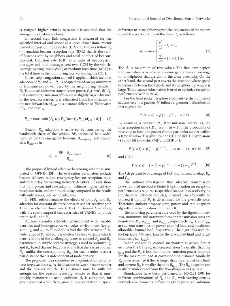
power control method is better if optimization on receptionperformance is required at specific distance. In case of varyingthe distance between vehicles, channel can efficiently beutilized if optimal 𝑃tx is determined for the given distance.Therefore, authors propose joint power and rate adaptionalgorithm, which is shown in Figure 8.
The following parameters are used by the algorithm: cur-rent,minimum, andmaximum beacon transmission rates aredenoted as 𝑅tx, 𝑅txMIN
, and 𝑅txMAX, respectively. 𝑃tx, 𝑙, and 𝑙max
are current transmission power, channel load, andmaximumallowable channel load, respectively. The algorithm uses thelookup table 𝑓 to ascertain for the given load limit and targetdistance, 𝑓(𝑑
𝑡, 𝑙max).
When congestion control mechanism is active, first itestimates the 𝑙. The 𝑃tx is increased when 𝑙 is smaller than the𝑙max and the 𝑃tx is less than the transmission power requiredfor the maximum load at corresponding distance. Similarly,𝑃tx is decremented if the 𝑙 is larger than the channel load limitand current𝑅tx is smaller than the𝑅txmin
.The𝑅tx adaption caneasily be understood from the flow diagram in Figure 8.
Simulations have been performed in NS-2.34 [50] fordifferent combinations of 𝑃tx and 𝑅tx with varying densitynetwork environments. Efficiency of the proposed solutions
International Journal of Distributed Sensor Networks 11
Congestioncontrol start
Is congestion control active?
Yes
No
Yes
Yes
No
No
No
Yes
Yes
Congestioncontrol stop
Estimate l
l < ?
Increase Ptx
Increase Rtx
Rtx >
Decrease Ptx
Decrease RtxRtx <
Ptx < f(dt, lmax)?
lmax
Rtxmin?
Rtxmax?
Figure 8: Joint 𝑃tx and 𝑅tx algorithm [48].
is measure in terms of average IRT without optimization anddifference in average IRT with optimization for varying 𝑃tx,𝑅tx, and the number of nodes. Initially, authors have observedthat, for each sender-receiver distance and channel load,there exists a𝑃tx that achieves optimal reception performanceirrespective of network density. Separate 𝑃tx and 𝑅tx controlis applied to estimate optimal 𝑃tx and 𝑅tx values. Then, jointoptimal𝑃tx and𝑅tx controlmethod is investigated.At first, thejoint control method sets optimal𝑃tx for 𝑑𝑡, then it adjusts 𝑃txif there is any change in 𝑑
𝑟. The channel load is adjusted to be
within the min-max range or may further be more reducedthan the minimum value to achieve optimal 𝑃tx. The resultsshow that the proposed solutions efficiently approximate theoptimal performance.
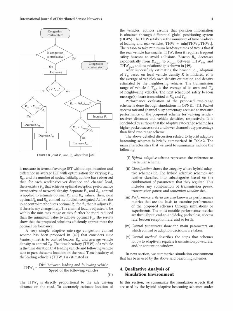
A very simple adaptive rate-rage congestion controlscheme has been proposed in [49] that considers timeheadway metric to control beacon 𝑅tx and average vehicledensity to control 𝑇
𝑅. The time headway (THW) of a vehicle
is the time duration that leading vehicle and following vehicletake to pass the same location on the road. Time headway ofthe leading vehicle 𝑗 (THW
𝑗) is estimated as
THW𝑗=Dist. between leading and following vehicle
Speed of the following vehicles.
(11)
The THW𝑗is directly proportional to the safe driving
distance on the road. To accurately estimate location of
the vehicles, authors assume that position informationis obtained through differential global positioning system(DGPS).TheTHW is taken as theminimumof time headwayof leading and rear vehicles, THW = min[THW
𝑗,THW
𝑟].
The reason to take minimum headway times of two is that ifthe rear vehicle has smaller THW, then it requires frequentsafety beacons to avoid collisions. Beacon 𝑅tx decreasesexponentially from 𝑅txMAX
to 𝑅txMINbetween THWmin and
THWmax and the relationship is shown in [49].After successfully estimating the beacon 𝑅tx, adaption
of 𝑇𝑅based on local vehicle density 𝐾 is initiated. 𝐾 is
the average of vehicle’s own density estimation and densityestimated by the neighboring vehicles. The transmissionrange of vehicle 𝑖, 𝑇
𝑅𝑖
, is the average of its own and 𝑇𝑅
of neighboring vehicles. The next scheduled safety beaconmessage(s) is/are transmitted at 𝑅tx and 𝑇𝑅.
Performance evaluation of the proposed rate-rangescheme is done through simulations in OPNET [51]. Packetsuccess rate and channel busy percentage are used tomeasureperformance of the proposed scheme for varying sender-receiver distances and vehicle densities, respectively. It isconcluded by authors that the adaptive rate-range scheme hashigher packet success rate and lower channel busy percentagethan fixed rate-range scheme.
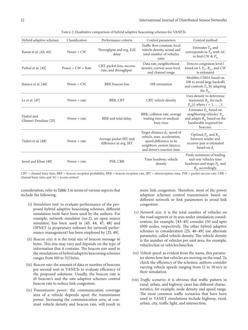
The above detailed discussion related to hybrid adaptivebeaconing schemes is briefly summarized in Table 2. Themain characteristics that we used to summarize include thefollowing.
(i) Hybrid adaptive scheme represents the reference toparticular scheme.
(ii) Classification shows the category where hybrid adap-tive schemes lie. The hybrid adaptive schemes arefurther classified into subcategories based on thecombination of parameters that they regulate. Thisincludes any combination of transmission power,transmission power, and contention window size.
(iii) Performance criteria are also known as performancemetrics that are the basis to examine performanceof the proposed schemes through simulations orexperiments. The most notable performance metricsare throughput, end-to-end delay, packet loss, successrate, beacon reception rate, and so forth.
(iv) Control parameters show the main parameters onwhich control or adaption decisions are taken.
(v) Control method describes the steps that schemesfollow to adaptively regulate transmission power, rate,and/or contention window.
In next section, we summarize simulation environmentthat has been used by the above said beaconing schemes.
4. Qualitative Analysis ofSimulation Environment
In this section, we summarize the simulation aspects thatare used by the hybrid adaptive beaconing schemes under
12 International Journal of Distributed Sensor Networks
Table 2: Qualitative comparison of hybrid adaptive beaconing schemes for VANETs.
Hybrid adaptive schemes Classification Performance criteria Control parameters Control method
Rawat et al. [43, 44] Power + CW Throughput and avg. E2Edelay
Traffic flow constant, localvehicle density, actual andtotal number of vehicles
ratio
Estimates 𝑇𝑅and
corresponds to 𝑇𝑅with AC
to find CW & 𝑃tx
Puthal et al. [45] Power + CW + Rate CBT, packet loss, successrate, and throughput.
Data rate, neighborhooddensity, current ueue level,
and channel usage
Detects congestion level 𝑙based on 𝑙, 𝑃tx, 𝑅tx, and CW
is estimated
Stanica et al. [46] Power + CW BRP, beacon loss SIR estimation
Modifies CSMA based onSIR to avoid large backoffsand controls 𝑇
𝑅by adapting
the 𝑃tx.
Le et al. [47] Power + rate BRR, CBT CBT, vehicle densityUses density to determinemaximum 𝑅tx for each𝑃tx[𝑖] where 𝑖 = 1, . . . , 5.
Djahel andGhamri-Doudane [25] Power + rate BRR and total delay.
BRR, collision rate, averagewaiting time or medium
busy time
Estimates 𝑃tx based onneighboring vehicles’ 𝑃tx
and adapts 𝑅tx based on thebandwidth required for
beacons.
Tielert et al. [48] Power + rate Average packet IRT anddifference in avg. IRT
Target distance 𝑑𝑡: speed of
vehicle, max. acceleration,speed difference to its
neighbors, system latency,and driver’s reaction time
Optimal 𝑃tx and 𝑅txbetween sender and
receiver pair is estimatedbased on 𝑑
𝑡
Javed and Khan [49] Power + rate PSR, CBR Time headway, vehicledensity
Finds minimum of leadingand rear vehicle’s time
headways and maps 𝑃tx and𝑅tx accordingly.
CBT = channel busy time, BRP = beacon reception probability, BRR = beacon reception rate, IRT = interreception time, PSR = packet success rate, CBR =channel busy ratio, and AC = access control.
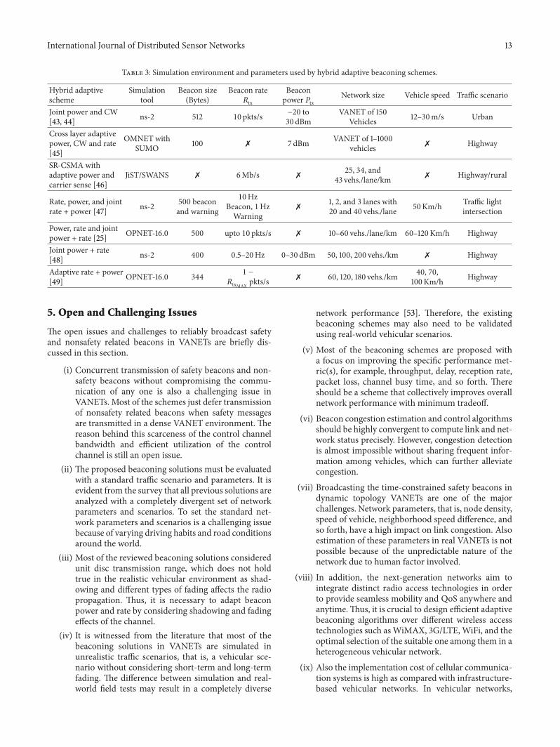
consideration; refer to Table 3 in terms of various aspects thatinclude the following.
(i) Simulation tool: to evaluate performance of the pro-posed hybrid adaptive beaconing schemes, differentsimulation tools have been used by the authors. Forexample, network simulator (ns-2), an open sourcesimulator, has been used in [43, 44, 47, 48] andOPNET (a proprietary software for network perfor-mance management) has been employed by [25, 49].
(ii) Beacon size: it is the total size of beacon message inbytes. This size may vary and depends on the type ofinformation that it contains. The beacon size used inthe simulations of hybrid adaptive beaconing schemesranges from 100 to 512 bytes.
(iii) Beacon rate: the amount of data or number of beaconsper second sent in VANETs to evaluate efficiency ofthe proposed solutions. Usually, the beacon rate is10 beacon/s and the rate adaptive schemes controlbeacon rate to reduce link congestion.
(iv) Transmission power: the communication coveragearea of a vehicle depends upon the transmissionpower. Increasing the communication area, at con-stant vehicle density and beacon rate, will result in
more link congestion. Therefore, most of the poweradaption schemes control transmission based ondifferent network or link parameters to avoid linkcongestion.
(v) Network size: it is the total number of vehicles onthe road segment or in area under simulation consid-eration; for example, [43–45] consider 150 and upto1000 nodes, respectively. The other hybrid adaptiveschemes in consideration [25, 46–49] use alternateparameter, called vehicle density. The vehicle densityis the number of vehicles per unit area, for example,vehicles/km or vehicles/lane/km.
(vi) Vehicle speed: as evident from the name, this parame-ter shows how fast vehicles aremoving on the road. Tocheck the efficiency of the schemes, authors considervarying vehicle speeds ranging from 12 to 30m/s intheir simulation.
(vii) Traffic scenario: it is obvious that traffic pattern inrural, urban, and highway cases has different charac-teristics, for example, node density and speed range.The most common traffic scenarios that have beenused in VANET simulations include highway, rural,urban, city, traffic light, and intersection.
International Journal of Distributed Sensor Networks 13
Table 3: Simulation environment and parameters used by hybrid adaptive beaconing schemes.
Hybrid adaptivescheme
Simulationtool
Beacon size(Bytes)
Beacon rate𝑅tx
Beaconpower 𝑃tx
Network size Vehicle speed Traffic scenario
Joint power and CW[43, 44] ns-2 512 10 pkts/s −20 to
30 dBmVANET of 150
Vehicles 12–30m/s Urban
Cross layer adaptivepower, CW and rate[45]
OMNET withSUMO 100 M 7 dBm VANET of 1–1000
vehicles M Highway
SR-CSMA withadaptive power andcarrier sense [46]
JiST/SWANS M 6Mb/s M 25, 34, and43 vehs./lane/km M Highway/rural
Rate, power, and jointrate + power [47] ns-2 500 beacon
and warning
10HzBeacon, 1HzWarning
M 1, 2, and 3 lanes with20 and 40 vehs./lane 50Km/h Traffic light
intersection
Power, rate and jointpower + rate [25] OPNET-16.0 500 upto 10 pkts/s M 10–60 vehs./lane/km 60–120Km/h Highway
Joint power + rate[48] ns-2 400 0.5–20Hz 0–30 dBm 50, 100, 200 vehs./km M Highway
Adaptive rate + power[49] OPNET-16.0 344 1 −
𝑅txMAXpkts/s M 60, 120, 180 vehs./km 40, 70,
100Km/h Highway
5. Open and Challenging Issues
The open issues and challenges to reliably broadcast safetyand nonsafety related beacons in VANETs are briefly dis-cussed in this section.
(i) Concurrent transmission of safety beacons and non-safety beacons without compromising the commu-nication of any one is also a challenging issue inVANETs. Most of the schemes just defer transmissionof nonsafety related beacons when safety messagesare transmitted in a dense VANET environment. Thereason behind this scarceness of the control channelbandwidth and efficient utilization of the controlchannel is still an open issue.
(ii) The proposed beaconing solutions must be evaluatedwith a standard traffic scenario and parameters. It isevident from the survey that all previous solutions areanalyzed with a completely divergent set of networkparameters and scenarios. To set the standard net-work parameters and scenarios is a challenging issuebecause of varying driving habits and road conditionsaround the world.
(iii) Most of the reviewed beaconing solutions consideredunit disc transmission range, which does not holdtrue in the realistic vehicular environment as shad-owing and different types of fading affects the radiopropagation. Thus, it is necessary to adapt beaconpower and rate by considering shadowing and fadingeffects of the channel.
(iv) It is witnessed from the literature that most of thebeaconing solutions in VANETs are simulated inunrealistic traffic scenarios, that is, a vehicular sce-nario without considering short-term and long-termfading. The difference between simulation and real-world field tests may result in a completely diverse
network performance [53]. Therefore, the existingbeaconing schemes may also need to be validatedusing real-world vehicular scenarios.
(v) Most of the beaconing schemes are proposed witha focus on improving the specific performance met-ric(s), for example, throughput, delay, reception rate,packet loss, channel busy time, and so forth. Thereshould be a scheme that collectively improves overallnetwork performance with minimum tradeoff.
(vi) Beacon congestion estimation and control algorithmsshould be highly convergent to compute link and net-work status precisely. However, congestion detectionis almost impossible without sharing frequent infor-mation among vehicles, which can further alleviatecongestion.
(vii) Broadcasting the time-constrained safety beacons indynamic topology VANETs are one of the majorchallenges. Network parameters, that is, node density,speed of vehicle, neighborhood speed difference, andso forth, have a high impact on link congestion. Alsoestimation of these parameters in real VANETs is notpossible because of the unpredictable nature of thenetwork due to human factor involved.
(viii) In addition, the next-generation networks aim tointegrate distinct radio access technologies in orderto provide seamless mobility and QoS anywhere andanytime.Thus, it is crucial to design efficient adaptivebeaconing algorithms over different wireless accesstechnologies such asWiMAX, 3G/LTE,WiFi, and theoptimal selection of the suitable one among them in aheterogeneous vehicular network.
(ix) Also the implementation cost of cellular communica-tion systems is high as compared with infrastructure-based vehicular networks. In vehicular networks,
14 International Journal of Distributed Sensor Networks
the access points can be used as an intermediate nodeto relay data packets to other vehicles in multihopfashion. Thus, designing efficient beaconing for V2Iin this environment can be used in various applica-tions such as electronic toll collection, and road-sideadvertisement services.
6. Conclusion
In this paper, we performed a comprehensive study of stateof the art hybrid adaptive beaconing schemes proposed forVANETs. The parameters on which these schemes optimizethe combination of beacon power, rate, and/or CW, alongwith their working principles, are discussed in detail. Finally,the evaluation and simulation parameters are summarizedin detail to easily insight the contrast between all schemesin literature. In addition, we also provide a list of openchallenges and future directions, where we aim to motivatefurther research interest for existing beaconing constraints inVANETs.
Conflict of Interests
The authors declare that there is no conflict of interestsregarding publication of this paper.
Acknowledgments
This research was supported by the MSIP (Ministry ofScience, ICT & Future Planning), Korea, under the C-ITRC(Convergence Information Technology Research Center)support program (NIPA-2014-H0401-14-1004) supervised bythe NIPA (National IT Industry Promotion Agency). Thisresearch was also supported by the Basic Science ResearchProgram through theNational Research Foundation of Korea(NRF) funded by the Ministry of Education, Science andTechnology (2012R1A1A4A01009954).
References
[1] S. Al-Sultan, M. M. Al-Doori, A. H. Al-Bayatti, and H. Zedan,“A comprehensive survey on vehicular Ad Hoc network,”Journal of Network and Computer Applications, vol. 37, no. 1, pp.380–392, 2014.
[2] F. D. da Cunha, A. Boukerche, L. Villas, V. Aline, and A.A. F. Loureiro, “Data communication in VANETs: a survey,challenges and applications,” Research Report RR-8498, Ver-sion 2, INRIA, 2014, https://hal.inria.fr/hal-00981126/PDF/RR-8498.pdf.
[3] SAE Std. J2735, Dedicated Short Range Communications(DSRC) Message Set Dictionary, 2009.
[4] J. B. Kenney, “Dedicated short-range communications (DSRC)standards in the United States,” Proceedings of the IEEE, vol. 99,no. 7, pp. 1162–1182, 2011.
[5] IEEE Std 1609.3–2010 (Revision of IEEE Std 1609.3-2007),“IEEE Standard forWireless Access in Vehicular Environments(WAVE)Networking Services”.
[6] A. Benslimane, T. Taleb, and R. Sivaraj, “Dynamic clustering-based adaptive mobile gateway management in integrated
VANET 3G heterogeneous wireless networks,” IEEE Journal onSelected Areas in Communications, vol. 29, no. 3, pp. 559–570,2011.
[7] B. Aslam, P. Wang, and C. C. Zou, “Extension of internet accessto VANET via satellite receive-only terminals,” InternationalJournal of Ad Hoc and Ubiquitous Computing, vol. 14, no. 3, pp.172–190, 2013.
[8] L. S. Mojela andM. J. Booysen, “On the use ofWiMAX andWi-Fi to provide in-vehicle connectivity andmedia distribution,” inProceedings of the IEEE International Conference on IndustrialTechnology (ICIT ’13), pp. 1353–1358, February 2013.
[9] The CAMP Vehicle Safety Communications Consortium,“Vehicle safety communications project task 3 final reportiden-tify intelligent vehicle safety applications enabled by DSRC,”Tech. Rep. DOT HS 809 859, NHTSA, US Department ofTransportation, Washington, DC, USA, 2005.
[10] W. K. Wolterink, G. J. Heijenk, and G. Karagiannis, “Informa-tion dissemination in VANETS by piggybacking on beacons—an analysis of the impact of network parameters,” in Proceedingsof the IEEE Vehicular Networking Conference (VNC ’11), pp. 94–101, November 2011.
[11] K. Z. Ghafoor, J. Lloret, K. A. Bakar, A. S. Sadiq, and S. A. B.Mussa, “Beaconing approaches in vehicular Ad hoc networks:a survey,” Wireless Personal Communications, vol. 73, no. 3, pp.885–912, 2013.
[12] H. Song andH. S. Lee, “A survey on how to solve a decentralizedcongestion control problem for periodic beacon broadcast invehicular safety communications,” in Proceedings of the 15thInternational Conference on Advanced Communication Tech-nology (ICACT ’13), pp. 649–654, PyeongChang, Republic ofKorea, January 2013.
[13] SAE J2735, “DSRC Implementation Guide: a guide to usersof SAE J2735 message sets over DSRC,” SAE International,http://www.sae.org/standardsdev/dsrc/DSRCImplementation-Guide.pdf.
[14] R. Stanica, E. Chaput, and A.-L. Beylot, “Properties of theMAClayer in safety vehicular ad hoc networks,” IEEE Communica-tions Magazine, vol. 50, no. 5, pp. 192–200, 2012.
[15] Q. Yang, J. Zheng, and L. Shen, “Modeling and performanceanalysis of periodic broadcast in vehicular ad hoc networks,” inProceedings of the IEEE Global Telecommunications Conference(GLOBECOM ’11), pp. 1–5, IEEE,Houston, Tex, USA,December2011.
[16] V.Naumov andT. R.Gross, “Connectivity-aware routing (CAR)in vehicular ad-hoc networks,” in Proceedings of the 26thIEEE International Conference on Computer Communications(INFOCOM ’07), pp. 1919–1927, May 2007.
[17] A. Boukerche, C. Rezende, and R. W. Pazzi, “Improving neigh-bor localization in vehicular ad hoc networks to avoid overheadfrom periodic messages,” in IEEE Global TelecommunicationsConference (GLOBECOM '09), pp. 1–6, Honolulu, Hawaii, USA,November-December 2009.
[18] R. K. Schmidt, T. Leinmuller, E. Schoch, F. Kargl, andG. Schafer,“Exploration of adaptive beaconing for efficient intervehiclesafety communication,” IEEE Network, vol. 24, no. 1, pp. 14–19,2010.
[19] C. Thaina, K. N. Nakorn, and K. Rojviboonchai, “A study ofadaptive beacon transmission on Vehicular Ad-Hoc Networks,”in Proceedings of the IEEE 13th International Conference onCommunication Technology (ICCT ’11), pp. 597–602, September2011.
International Journal of Distributed Sensor Networks 15
[20] T. Tielert, D. Jiang, Q. Chen, L. Delgrossi, and H. Hartenstein,“Design methodology and evaluation of rate adaptation basedcongestion control for vehicle safety communications,” in Pro-ceedings of the IEEE Vehicular Networking Conference (VNC ’11),pp. 116–123, November 2011.
[21] C. Sommer, O. K. Tonguz, and F. Dressler, “Adaptive beaconingfor delay-sensitive and congestion-aware traffic informationsystems,” in Proceedings of the IEEE Vehicular NetworkingConference (VNC ’10), pp. 1–8, December 2010.
[22] C. Sommer, O. K. Tonguz, and F. Dressler, “Traffic informationsystems: efficient message dissemination via adaptive beacon-ing,” IEEECommunicationsMagazine, vol. 49, no. 5, pp. 173–179,2011.
[23] J.He,H.-H.Chen, T.M.Chen, andW.Cheng, “Adaptive conges-tion control for DSRC vehicle networks,” IEEE CommunicationsLetters, vol. 14, no. 2, pp. 127–129, 2010.
[24] W. Guan, J. He, L. Bai, and Z. Tang, “Adaptive rate control ofdedicated short range communications based vehicle networksfor road safety applications,” in Proceedings of the IEEE 73rdVehicular Technology Conference (VTC ’11), pp. 1–5, May 2011.
[25] S. Djahel andY.Ghamri-Doudane, “A robust congestion controlscheme for fast and reliable dissemination of safety messages inVANETs,” in Proceedings of the IEEE Wireless Communicationsand Networking Conference (WCNC ’12), pp. 2264–2269, Shang-hai, China, April 2012.
[26] H. Lv, X. Ye, L. An, and Y.Wang, “Distributed beacon frequencycontrol algorithm for VANETs (DBFC),” in Proceedings of the2nd International Conference on Intelligent Systems Design andEngineering Applications (ISDEA ’12), pp. 243–246, January2012.
[27] K. Z. Ghafoor, K. A. Bakar, E. M. van Eenennaam, R. H.Khokhar, and A. J. Gonzalez, “A fuzzy logic approach tobeaconing for vehicular ad hoc networks,” TelecommunicationSystems, vol. 52, no. 1, pp. 139–149, 2013.
[28] N. Chaabouni, A. Hafid, and P. K. Sahu, “A collision-basedbeacon rate adaptation scheme (CBA) for VANETs,” in Proceed-ings of the IEEE International Conference on Advanced Networksand Telecommunications Systems (ANTS ’13), pp. 1–6, December2013.
[29] C. Sommer, S. Joerer, M. Segata, O. Tonguz, R. Lo Cigno, andF. Dressler, “How shadowing hurts vehicular communicationsand how dynamic beaconing can help,” IEEE Transaction onMobile Computing, no. 99, p. 1, 2014.
[30] M. M. Artimy, W. Robertson, and W. J. Phillips, “Assignmentof dynamic transmission on estimation of vehicle density,”in Proceedings of the 2nd ACM International Workshop onVehicular AdHoc Networks (VANET ’05), pp. 40–48, September2005.
[31] M. Torrent-Moreno, P. Santi, and H. Hartenstein, “Fair sharingof bandwidth in VANETs,” in Proceedings of the 2nd ACMInternationalWorkshop onVehicular AdHocNetworks, (VANET’05), pp. 49–58, 2005.
[32] M. Torrent-Moreno, P. Santi, and H. Hartenstein, “Distributedfair transmit power adjustment for vehicular ad hoc networks,”in Proceedings of the 3rd Annual IEEE Communications Societyon Sensor and Ad Hoc Communications and Networks (SECON'06), vol. 2, pp. 479–488, Reston, Va, USA, September 2006.
[33] C. Chigan and J. Li, “A delay-bounded dynamic interactivepower conftol algorithm for VANETs,” in Proceedings of theIEEE International Conference on Communications (ICC ’07),pp. 5849–5855, June 2007.
[34] J. Mittag, F. Schmidt-Eisenlohr, M. Killat, J. Harri, and H.Hartenstein, “Analysis and design of effective and low-overheadtransmission power control for VANETs,” in Proceedings ofthe 5th ACM International Workshop on VehiculAr Inter-NETworking (VANET ’08), pp. 39–48, September 2008.
[35] M. Torrent-Moreno, J. Mittag, P. Santi, and H. Hartenstein,“Vehicle-to-vehicle communication: fair transmit power con-trol for safety-critical information,” IEEE Transactions on Vehic-ular Technology, vol. 58, no. 7, pp. 3684–3703, 2009.
[36] H. Lu and C. Poellabauer, “Balancing broadcast reliabilityand transmission range in VANETs,” in Proceedings of theIEEE Vehicular Networking Conference (VNC ’10), pp. 247–254,December 2010.
[37] K. A. Hafeez, L. Zhao, Z. Liao, and B. N.-W. Ma, “A newbroadcast protocol for vehicular ad hoc networks safety applica-tions,” in Proceedings of the 53rd IEEE Global CommunicationsConference (GLOBECOM ’10), pp. 1–5, December 2010.
[38] G. Samara and T. Alhmiedat, “Intelligent emergency messagebroadcasting in VANET using PSO,”World of Computer Scienceand Information Technology Journal, vol. 4, no. 7, pp. 90–100,2014.
[39] R. Reinders, M. Van Eenennaam, G. Karagiannis, and G. Hei-jenk, “Contention window analysis for beaconing in VANETs,”in Proceedings of the 7th International Wireless Communicationsand Mobile Computing Conference (IWCMC ’11), pp. 1481–1487,July 2011.
[40] Y. Wang, A. Ahmed, B. Krishnamachari, and K. Psounis, “IEEE802.11p performance evaluation and protocol enhancement,” inProceedings of the IEEE International Conference on VehicularElectronics and Safety (ICVES ’08), pp. 317–322, Columbus,Ohio, USA, September 2008.
[41] E. M. van Eenennaam, G. Karagiannis, and G. Heijenk,“Towards scalable beaconing in VANETs,” in Proceedings of theERCIM Workshop on eMobility, pp. 103–108, Lulea, Sweden,2010.
[42] R. Stanica, E. Chaput, and A.-L. Beylot, “Broadcast commu-nication in Vehicular Ad-Hoc Network safety applications,”in Proceedings of the IEEE Consumer Communications andNetworking Conference (CCNC ’11), pp. 462–466, January 2011.
[43] D. B. Rawat, G. Yan, D. C. Popescu, M. C. Weigle, and S.Olariu, “Dynamic adaptation of joint transmission power andcontention window in VANET,” in Proceedings of the IEEE 70thVehicular Technology Conference Fall (VTC-Fall ’09), pp. 1–5,Anchorage, Alaska, USA, September 2009.
[44] D. B. Rawat, D. C. Popescu, G. Yan, and S. Olariu, “EnhancingVANETperformance by joint adaptation of transmission powerand contention window size,” IEEE Transactions on Parallel andDistributed Systems, vol. 22, no. 9, pp. 1528–1535, 2011.
[45] D. Puthal, Z. H. Mir, F. Filali, and H. Menouar, “Cross-layer architecture for congestion control in Vehicular Ad-hoc Networks,” in Proceedings of the 2nd IEEE InternationalConference on Connected Vehicles and Expo (ICCVE ’13), pp.887–892, December 2013.
[46] R. Stanica, E. Chaput, and A.-L. Beylot, “Congestion controlin CSMA-based vehicular networks: do not forget the carriersensing,” inProceedings of the 9thAnnual IEEECommunicationsSociety Conference on Sensor,Mesh andAdHocCommunicationsand Networks (SECON ’12), pp. 650–658, Seoul, Republic ofKorea, June 2012.
[47] L. Le, R. Baldessari, P. Salvador, A. Festag, and W. Zhang, “Per-formance evaluation of beacon congestion control algorithms
16 International Journal of Distributed Sensor Networks
for VANETs,” in Proceedings of the IEEE Global Telecommunica-tions Conference (GLOBECOM ’11), pp. 1–6, Houston, Tex, USA,December 2011.
[48] T. Tielert, D. Jiang, H. Hartenstein, and L. Delgrossi, “Jointpower/rate congestion control optimizing packet reception invehicle safety communications,” in Proceedings of the 10th ACMInternational Workshop on Vehicular Inter-Networking, Systems,and Applications (VANET ’13), pp. 51–60, Taipei, Taiwan, June2013.
[49] M. A. Javed and J. Y. Khan, “Performance analysis of an adaptiverate-range control algorithm for VANET safety applications,”in Proceedings of the International Conference on Computing,Networking and Communications (ICNC ’14), pp. 418–423,February 2014.
[50] “TheNetwork Simulator—ns-2,” http://www.isi.edu/nsnam/ns/.[51] OPNET Technologies, “OPNET modeler,” http://www.opnet
.com/.[52] R. Barr, Z. J. Haas, and R. van Renesse, “JiST: an efficient
approach to simulation using virtual machines,” Software—Practice & Experience, vol. 35, no. 6, pp. 539–576, 2005.
[53] W. Liang, Z. Li, H. Zhang, S. Wang, and R. Bie, “Vehicularad hoc networks: architectures, research issues, methodologies,challenges, and trends,” Article ID 745303, International Journalof Distributed Sensor Networks. In press.

International Journal of
AerospaceEngineeringHindawi Publishing Corporationhttp://www.hindawi.com Volume 2014
RoboticsJournal of
Hindawi Publishing Corporationhttp://www.hindawi.com Volume 2014
Hindawi Publishing Corporationhttp://www.hindawi.com Volume 2014
Active and Passive Electronic Components
Control Scienceand Engineering
Journal of
Hindawi Publishing Corporationhttp://www.hindawi.com Volume 2014
International Journal of
RotatingMachinery
Hindawi Publishing Corporationhttp://www.hindawi.com Volume 2014
Hindawi Publishing Corporation http://www.hindawi.com
Journal ofEngineeringVolume 2014
Submit your manuscripts athttp://www.hindawi.com
VLSI Design
Hindawi Publishing Corporationhttp://www.hindawi.com Volume 2014
Hindawi Publishing Corporationhttp://www.hindawi.com Volume 2014
Shock and Vibration
Hindawi Publishing Corporationhttp://www.hindawi.com Volume 2014
Civil EngineeringAdvances in
Acoustics and VibrationAdvances in
Hindawi Publishing Corporationhttp://www.hindawi.com Volume 2014
Hindawi Publishing Corporationhttp://www.hindawi.com Volume 2014
Electrical and Computer Engineering
Journal of
Advances inOptoElectronics
Hindawi Publishing Corporation http://www.hindawi.com
Volume 2014
The Scientific World JournalHindawi Publishing Corporation http://www.hindawi.com Volume 2014
SensorsJournal of
Hindawi Publishing Corporationhttp://www.hindawi.com Volume 2014
Modelling & Simulation in EngineeringHindawi Publishing Corporation http://www.hindawi.com Volume 2014
Hindawi Publishing Corporationhttp://www.hindawi.com Volume 2014
Chemical EngineeringInternational Journal of Antennas and
Propagation
International Journal of
Hindawi Publishing Corporationhttp://www.hindawi.com Volume 2014
Hindawi Publishing Corporationhttp://www.hindawi.com Volume 2014
Navigation and Observation
International Journal of
Hindawi Publishing Corporationhttp://www.hindawi.com Volume 2014
DistributedSensor Networks
International Journal of


![Adaptive Learning-Based Task Offloading for …arXiv:1901.05205v1 [cs.IT] 16 Jan 2019 1 Adaptive Learning-Based Task Offloading for Vehicular Edge Computing Systems Yuxuan Sun, Student](https://img.pdfslide.net/doc/110x75/5f4218991041c135fa00276e/adaptive-learning-based-task-ofioading-for-arxiv190105205v1-csit-16-jan-2019.jpg)