Embed Size (px)
Citation preview

Hindawi Publishing CorporationInternational Journal of Antennas and PropagationVolume 2013, Article ID 102925, 11 pageshttp://dx.doi.org/10.1155/2013/102925
Review ArticleOverview on Multipattern and Multipolarization Antennas forAerospace and Terrestrial Applications
Aixin Chen,1 Weiwei Jiang,1 Zhizhang Chen,2 and Jiaheng Wang1
1 School of Electronic and Information Engineering, Beihang University, Beijing 100191, China2Department of Electrical and Computer Engineering, Dalhousie University, Halifax, NS, Canada B3J 2X4
Correspondence should be addressed to Aixin Chen; [email protected]
Received 17 February 2013; Accepted 12 March 2013
Academic Editor: Haiwen Liu
Copyright © 2013 Aixin Chen et al. This is an open access article distributed under the Creative Commons Attribution License,which permits unrestricted use, distribution, and reproduction in any medium, provided the original work is properly cited.
In recent years, reconfigurable antennas, with the ability to radiate wave in more than one pattern and polarization, play a great rolein modern telecommunication systems. Compared with conventional antennas, multipattern and multipolarization antennas havemore advantages and better prospects. They can be used to improve system gain and security, satisfy system requirements, avoidnoisy environment, and adapt to the environment flexibly.This paper discusses different patterns and polarizations of reconfigurableantennas according to current research work in this area. In the opinion of this paper, the radiation pattern states of antennasinclude beam direction, shape, and gain.The polarization states of antennas include horizontal/vertical linear, ±slant 45∘ linear, left-hand or right-hand circular polarized. Different multipattern and multipolarization antennas with various structures and workingmechanisms are compared and discussed. Multipattern and multipolarization antennas have been well applied for aerospace andterrestrial applications, such as dynamic scenarios, adaptive beam scanning, andmultiple-input-multiple-output (MIMO) systems.
1. Introduction
Generally, as we know, theconventional antennas only canwork in one radiation pattern and polarization. When theenvironmental conditions or system requirements change, weneed to reconfigure an antenna. It is inconvenient and coststoomuch. Reconfigurable antennas are a solution to solve thisproblem. They can change their radiation pattern and polar-ization timely to address complex system requirements bymodifying their geometry and electrical behavior. Reconfig-urable antennas can either increase the capabilities of wirelessintegrated information systems, expand their functionality,orwiden their bandwidths, with efficient spectrum and powerutilization.
Compared to today’s radio technology which depends onincompatible communication systems with inflexible hard-ware, the technology of reconfigurability will significantlyreduce the hardware complexity, the number of components,and the cost. As described above, reconfigurable antennaspromise to bring a host of benefits to future generation ofwireless systems. Next-generation communication systems
will rely upon reconfigurable antennas, such as wireless sys-tems in dynamic scenarios (e.g., satellite/terminal tracking),adaptive beam scanning (e.g., radar/remote sensing), andMIMO systems (e.g., active management of channel corre-lation/diversity/interference). Among diversity of schemes atantenna level, multipattern and multipolarization antennasare important ones. They can be used to improve systemgain and security, satisfy system requirement, avoid noisyenvironment, and adapt to the environment flexibly.
The concept of reconfigurable antenna was first presentedin 1983 [1] and further investigation and realization werecarried out and results were reported in [2]. In the recentyears, reconfigurable antennas attracted more and moreattention due to their capability of providing multipatternand multipolarization. One of the important applications isin aerospace and terrestrial wireless communication systems.
In the following sections, the classification of the mul-tipattern and multipolarization antennas, the comparisonbetween the different antennas with various structures andworking mechanisms, the field of their application, and thevision and goal are to be discussed.

2 International Journal of Antennas and Propagation
Multi-pattern antenna
Beam shape GainBeam direction
Omni-directional Directional Main lobe level Side lobe levelMultiplebeams
Figure 1: Classification of multipattern antennas.
Multi-polarization antenna
Circle polarizationLinear polarization
Horizontal Vertical Left-hand Right-hand±slant 45 (deg)
Figure 2: Classification of multipolarization antennas.
2. Classification and Technologies ofReconfigurable Antennas
In this paper, the reconfigurable antennas (mainly multipat-tern and multipolarization antennas here) can be classifiedinto three categories: multipattern antennas, multipolar-ization antennas, and multipattern-multipolarization mixedreconfigurable antennas.
The multipattern antennas are divided into three majortypes achieved by changing the beam direction, beamshape, and gain, as indicated in Figure 1. The beam direc-tion includes the omnidirectional and directional direction.Antennas which alter between omni-directional and direc-tional radiation patterns [3–8] or vary the direction fromone side to another side [9–17] are called the beam directionreconfigurable antennas. Beam shape reconfigurable anten-nas can be achieved by changing the number of beams(multiple beams) [18–21]. Finally, the gain reconfigurableantennas are able to be realized by changing the shape ofbeam’s main lobe and side lobe [22–24].
Themultipolarization antennas include linearly polarizedantennas and circularly polarized antennas, as shown inFigure 2. A radiating structure that is able to change itspolarization (horizontal, vertical, and radiations, and ±slant45∘) is called linear polarization reconfigurable antennas[25–30]. Circular polarization reconfigurable antennas areachieved by varying polarization between left-hand circularand right-hand circular [31–39]. The antennas switchingbetween the linear polarization and circular polarization aremixed polarization reconfigurable antennas [40–51].
Themultipattern-multipolarizationmixed reconfigurableantennas are the antennas which combine multipattern withmultipolarization [52–61].
In order to realize various reconfigurable antennas, fivemajor technologies are introduced.
(i) Electronically tuned reactance: alter the capacitorsor inductors by varying the bias voltage. The com-mon elements are varactor diodes and microelectro-mechanical-system- (MEM-S) tunable capacitors/inductors.
(ii) Radio frequency (RF) electrical switches: by control-ling the voltage, achieve the switches to be “on” state orthe “off” state. PINdiodes, field effect transistor (FET)switches, and MEMS are popularly used.
(iii) Photoconductive switches: activate the semiconduc-tor material (silicon, gallium arsenide) by controllingthe laser light to realize the “on” state or the “off”state. It results in exciting electrons from the valenceto the conduction band and thus creates a conductiveconnection.
(iv) Exotic materials: a static applied electric/magneticfield or voltage can change the relative material per-mittivity/permeability.The smart materials which areused in the substrate of the reconfigurable antennasinclude nematic liquid crystals, nonlinear materials,and ferroelectric films.
(v) Structural alteration: by altering the height, acreage,and shape of antenna, the physical structural is ableto be modified. The altering structure is the antennaradiating parts.
The multipattern and multipolarization antennas aredesigned by implying the five major technologies to changesurface current distribution, and the feeding network, thephysical structure, the effective radiating aperture of anten-nas. The different patterns or polarizations correspond todifferent states caused by the technologies.
3. Multipattern Antennas
3.1. Beam Direction Reconfigurable Antennas. The conven-tional antennas can only work in the omni-directional ordirectional beam direction. The beam of omni-directionalantenna homogeneously directs all the direction. The beamof directional antenna only directs in some range, but itsradiated effect is better than that the omni-directional antenn.Consequently, we can choose the suitable type to meet theneed of communication system. For example, in the casethat the wireless access points distribute in different placesand are close to the antenna, we should choose the omni-directional antenna. On the contrary that the wireless accesspoints are put together in one direction and long away fromthe antenna, the directional antenna is our choice. So wecan see that the reconfigurable antenna with either omni-directional or directional radiation pattern is very usefulin wireless system. In addition, when the target is uniqueand always moves, for example, in the radar and terminal

International Journal of Antennas and Propagation 3
Chip inductor Chip inductor
Chip inductor
DC1Diode1
Diode2DC2
Diode3
Chip capacitor
(a)
Diode1Diode2
(b)
Figure 3: Radiation pattern reconfigurable antenna. (a) Side view.(b) Top view (redrawn after).
tracking system, the beamdirection of antenna should changeat the same time. The directional reconfigurable antenna fitsit well. Next, three different examples of beam direction ofreconfigurable antennas are described.
3.1.1. Beam Direction Reconfigurable Antennas with Omnidi-rectional and Directional Characteristics. This type of anten-nas can realize omni-directional and directional radiation.The antenna shown in Figure 3 is a simple radiation patternreconfigurable antenna. The antenna is a combination of amonopole antenna and a dipole antenna with reflector [3].Three switches are inserted to control the radiation patternof antenna. The reconfigurable antenna can be operated aseither amonopole antennawith an omnidirectional radiationpattern at the switches “on” state or a dipole antenna withreflector, which has directional radiation pattern at theswitches “off” state. The antenna is compact and easy tocontrol.
3.1.2. Beam Direction Reconfigurable Antennas with VariedDirectional Characteristics. This is a type of complex radia-tion pattern reconfigurable antennas. A reconfigurable leaky-wave antenna capable of steering its radiation beam overa wide range is discussed in [9]. The antenna system isa microstrip composite right/left-hand (CRLH) leaky-waveantenna composed by 25 cascaded metamaterial unit cells,as shown in Figure 4. To achieve the CRLH behavior, insertan artificial series capacitance and a shunt inductance intoa conventional microstrip line by means of an interdigitalcapacitor and a shorted stub, respectively. By tuning the biasvoltage of varactor diodes𝐷S and𝐷SH separately, we can steerthe radiation beam from −55∘ to 50∘.
The fabricated antenna shown in Figure 5(a) is a planar6× 6 fully reconfigurable array operating at 5.7 GHz, capableof functioning both as a reconfigurable array lens and
a reconfigurable reflectarray [10]. The array element consistsof two varactor diode-loaded patches coupled by a varactordiode-loaded slot, as shown in Figure 5(b). In the lens mode,the antenna has a broadside directivity of 20.8 dBi and abeam-scanning range of 50∘ by 50∘.The array as a reflectarraycan achieve a directivity of 19.4 dBi at broadside and a beam-scanning range of 60∘ by 30∘.This array is able to demonstratefull 2D beamforming with low cost and is easy to fabricate.
3.2. Beam Shape Reconfigurable Antennas. The antennaswhich radiate multiple beams at the same time are calledmultibeam antennas. Multibeam antennas are able to bothtransmit signal in multiple directions at the same time withhigh gain and achieve the low side lobe by controlling theamplitude and phase of the feeds. To meet the differentdemand of communication system, we can change the num-ber and shape of beams. Beam shape reconfigurable antennasare important and have been studied by many scientists.
Amultifunctional reconfigurable antenna (MRA) capableof steering its radiation beam in the azimuth plane into oneof 4 and 8 directions with variable beamwidth is presentedin [20] (see Figure 6). The antenna is composed of a planararray of electrically smallmetallic square-shaped pixelswhichare interconnected byMEMS switches. By activating or deac-tivating the interconnecting MEMS switches, the geometryof the MRA dipole is changed. The antenna with optimumperformance is able to apply for a wireless communicationsystem.
3.3. Gain Reconfigurable Antennas. The beam makes up bymain lobe and side lobe. In general, to improve the gain ofantenna, we should increase the mainlobe level and lower theside lobe level as far as possible.
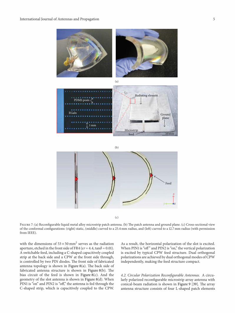
A flexible microstrip patch antenna incorporates a novelmultilayer construction consisting of a liquid metal (eutecticgallium indium) encased in an elastomer [24]. The antennais flexible and durable as its combined properties of the fluidand the elastomeric substrate, as shown in Figure 7(a). Inject-ing the metal into micro-fluidic channels provides a simpleway to define the shape of the liquid, which is stabilizedmechanically by a thin oxide skin that forms spontaneouslyon its surface. In Figure 7(b), a multilayer patch antennais fabricated using specially designed serpentine channelsthat take advantage of the unique rheological property ofthe liquid metal alloy. And in Figure 7(c), by controlling theshape of antenna static, curving a low dielectric mandrel witha radius of 12.7mm, and curving around a similar mandrelwith a radius of 25.4 cm, separately, the antenna can realizethree different values of gain. The flexibility antenna is wellsuited for conformal antenna applications.
4. Multipolarization Antennas
Comparing with classical antennas with single polarization,the multipolarization antennas offer advantages of reductionin installation space, low coupling effect, and low installationcost. Their intrinsic polarization diversity advantage is veryuseful in mitigating the multipath fading and increasing the

4 International Journal of Antennas and Propagation
SH
DS
7 mm
𝜆/4
𝜆/4 𝜆/4 𝜆/4
DC bias for𝐷SH (SH)
𝐷SH𝐷SH
𝑌SH
𝑍𝑠𝑍𝑠𝑆
Port 1 Port 2
“S” bias
“SH” bias
5.5
cm
17.5 cm
𝐶𝐶
𝐷𝑆 𝐷𝑆
DC bias for 𝐷𝑆 (𝑆)
Figure 4: Two-port reconfigurable leaky-wave antenna and its tunable unit cell design (with permission from IEEE).
180mm
180mm
30mm
30mm
40-pin
ribboncables
𝐸-plane
𝐻-plane
(a)
Bias ground line
Patch bias lines
Uppersubstrate
Bonding film gapSlotSlot bias
Lowersubstrate
10K resistors
Varactordiodes
(b)
Figure 5: (a) Fabricated 6× 6 planar reconfigurable array. (b) Arrayelement and bias network design (vertically exaggerated) (withpermission from IEEE).
𝑋
𝑌
RF port
0.82.4
746
49.6
Figure 6: Multifunctional reconfigurable antenna (with permissionfrom IEEE).
channel capacity, especially in polarization-varied environ-ment. Such antennas can switch between linear polarization(LP) and circle polarization (CP), depending on the sys-tem requirements. The kinds of linear polarization includehorizontal, vertical, and ±slant 45∘ polarization. The typesof circular polarization are right-hand circular polarization(RHCP) and left-hand circular polarization (LHCP). In thissection, three different polarization reconfigurable antennasto adjust the different propagation environment are presentedas examples.
4.1. Linear Polarization Reconfigurable Antennas. A polar-ization reconfigurable slot antenna with compact feed ispresented in [27]. Fed by dual modes of coplanar waveguide,dual orthogonal linear polarizations are excited in the slot andcontrolled by two PIN diodes. The antenna is composed by arectangular slot, a coplanar waveguide (CPW), a capacitivelycoupled strip, and two PIN diodes. The rectangular slot
International Journal of Antennas and Propagation 5
(a)
PDMS posts
EGaln
1mm
Radiating element
Microstripfeed
Groundplane
10mm
(b)
𝑥
𝑦 𝑧
Feed
(c)
Figure 7: (a) Reconfigurable liquid metal alloy microstrip patch antenna. (b) The patch antenna and ground plane. (c) Cross-sectional viewof the conformal configurations: (right) static, (middle) curved to a 25.4mm radius, and (left) curved to a 12.7mm radius (with permissionfrom IEEE).
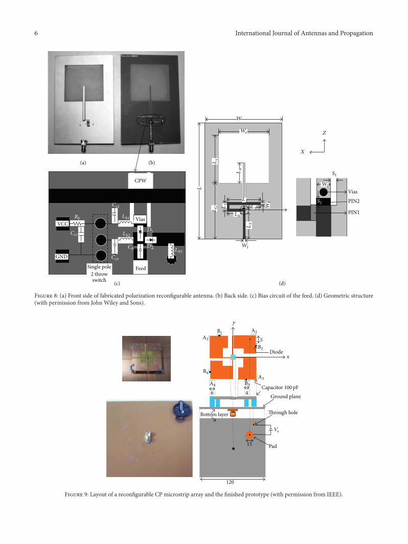
with the dimensions of 53× 50mm2 serves as the radiationaperture, etched in the front side of FR4 (𝜀r = 4.4, tan𝛿= 0.01).A switchable feed, including a C-shaped capacitively coupledstrip at the back side and a CPW at the front side through,is controlled by two PIN diodes. The front side of fabricatedantenna topology is shown in Figure 8(a). The back side offabricated antenna structure is shown in Figure 8(b). Thebias circuit of the feed is shown in Figure 8(c). And thegeometry of the slot antenna is shown in Figure 8(d). WhenPIN1 is “on” and PIN2 is “off,” the antenna is fed through theC-shaped strip, which is capacitively coupled to the CPW.
As a result, the horizontal polarization of the slot is excited.When PIN1 is “off” and PIN2 is “on,” the vertical polarizationis excited by typical CPW feed structure. Dual orthogonalpolarizations are achieved by dual orthogonalmodes of CPWindependently, making the feed structure compact.
4.2. Circular Polarization Reconfigurable Antennas. A circu-larly polarized reconfigurable microstrip array antenna withconical-beam radiation is shown in Figure 9 [39]. The arrayantenna structure consists of four L-shaped patch elements
6 International Journal of Antennas and Propagation
(a) (b)
(c) (d)
CPW
VCC
GND
Single pole2 throwswitch
Vias
Feed
𝑅𝑏
𝐶𝑠1
𝐶𝑠2
𝐷1
𝐷2
𝐿𝑏1
𝐶𝑠3
𝑊
𝑊𝑠
𝐿𝑠
𝐿𝐺 𝑊
1
Vias
𝐿1
𝐿0
𝐿3
𝐿4
𝐿5
𝐿
𝑊1
𝑋
𝑍
𝑆1
𝑊1
𝑆2
PIN1
PIN2𝐿2
𝐶𝑏
𝐿𝑏2
𝐿𝑏3
Figure 8: (a) Front side of fabricated polarization reconfigurable antenna. (b) Back side. (c) Bias circuit of the feed. (d) Geometric structure(with permission from John Wiley and Sons).
Bottom layer
Pad
Through hole
Ground plane
𝑦
Diode
120
15
6 4
5
𝑉𝑠
A1A2
A3A4
B1
B2
B3
B4
𝑥
Capacitor 100pF
Figure 9: Layout of a reconfigurable CP microstrip array and the finished prototype (with permission from IEEE).
International Journal of Antennas and Propagation 7
Interdigitalcapacitor
Top layer:copper
Ground layer:copper
Vias
Substrate
𝑦 𝑥𝑧
𝑝
𝐿
𝑤1
𝑤2
𝑤3
(a)
Wave propagationBwd
Fwd
𝑦𝑥
𝑧𝑓broadside
𝑓 𝜃
𝑝1
𝑝2
𝑝3
𝑝4𝐵 = −𝑘0 (𝜃 = −90 ∘)
𝐵=𝑘0 (𝜃 =90 ∘)
𝑓backfire
𝑓endfire𝛽 < 0 𝛽 > 0
(b)
(c) (d)
Figure 10: Polarization reconfigurable CRLH-SIW antenna. (a) Single radiating element. (b) Two-element unit cell of the whole structure.(c) Overall LW antenna prototype. (d) fabricated antenna (with permission from IEEE).
arranged in a square-ring formation. Each patch is shortedto the ground plane through conducting walls. With a top-loaded monopole feed, two orthogonal resonant modes, loopmode and monopole mode, can be excited simultaneously.When the monopole mode and the loop mode are properlycoupled, the microstrip array can generate a CP radiation.By controlling the frequency, the antenna can switch betweenLHCP and RHCP. In addition the array has the characteristicof omnidirectional radiation and conical beam.
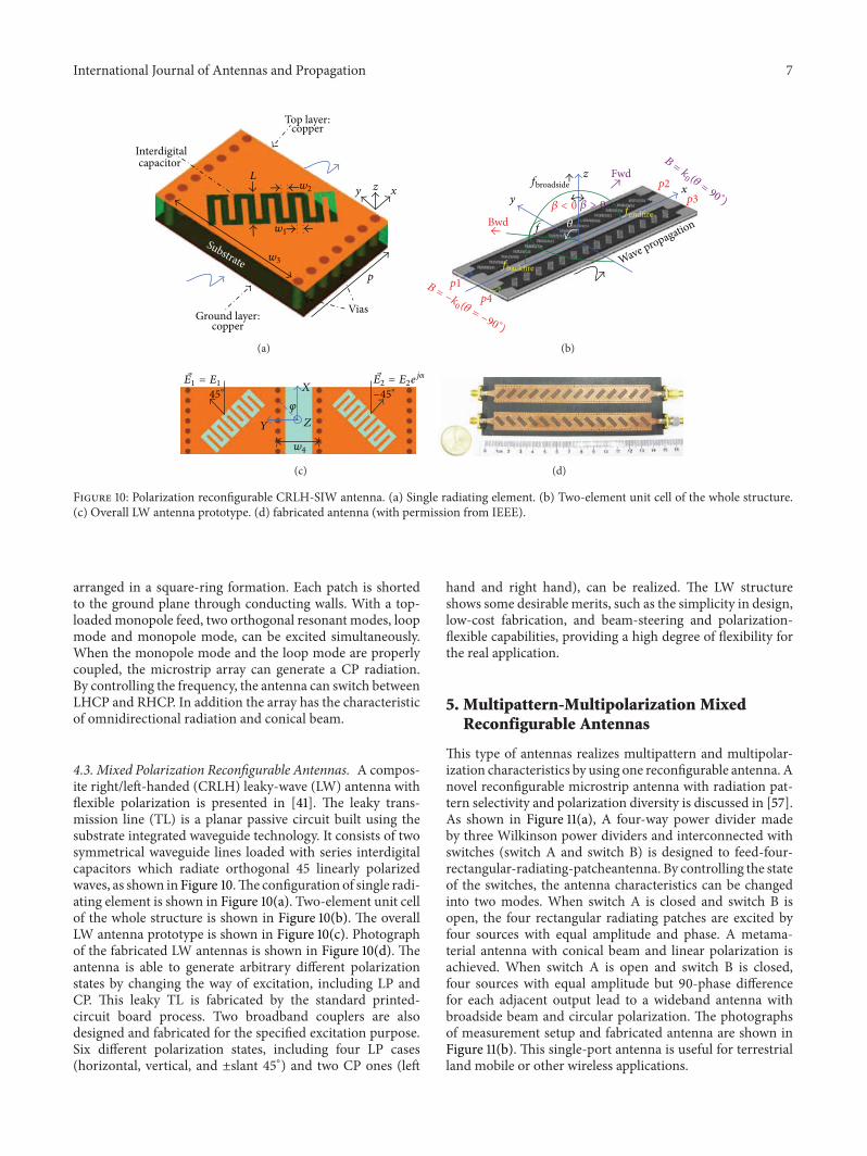
4.3. Mixed Polarization Reconfigurable Antennas. A compos-ite right/left-handed (CRLH) leaky-wave (LW) antenna withflexible polarization is presented in [41]. The leaky trans-mission line (TL) is a planar passive circuit built using thesubstrate integrated waveguide technology. It consists of twosymmetrical waveguide lines loaded with series interdigitalcapacitors which radiate orthogonal 45 linearly polarizedwaves, as shown in Figure 10.The configuration of single radi-ating element is shown in Figure 10(a). Two-element unit cellof the whole structure is shown in Figure 10(b). The overallLW antenna prototype is shown in Figure 10(c). Photographof the fabricated LW antennas is shown in Figure 10(d). Theantenna is able to generate arbitrary different polarizationstates by changing the way of excitation, including LP andCP. This leaky TL is fabricated by the standard printed-circuit board process. Two broadband couplers are alsodesigned and fabricated for the specified excitation purpose.Six different polarization states, including four LP cases(horizontal, vertical, and ±slant 45∘) and two CP ones (left
hand and right hand), can be realized. The LW structureshows some desirable merits, such as the simplicity in design,low-cost fabrication, and beam-steering and polarization-flexible capabilities, providing a high degree of flexibility forthe real application.
5. Multipattern-Multipolarization MixedReconfigurable Antennas
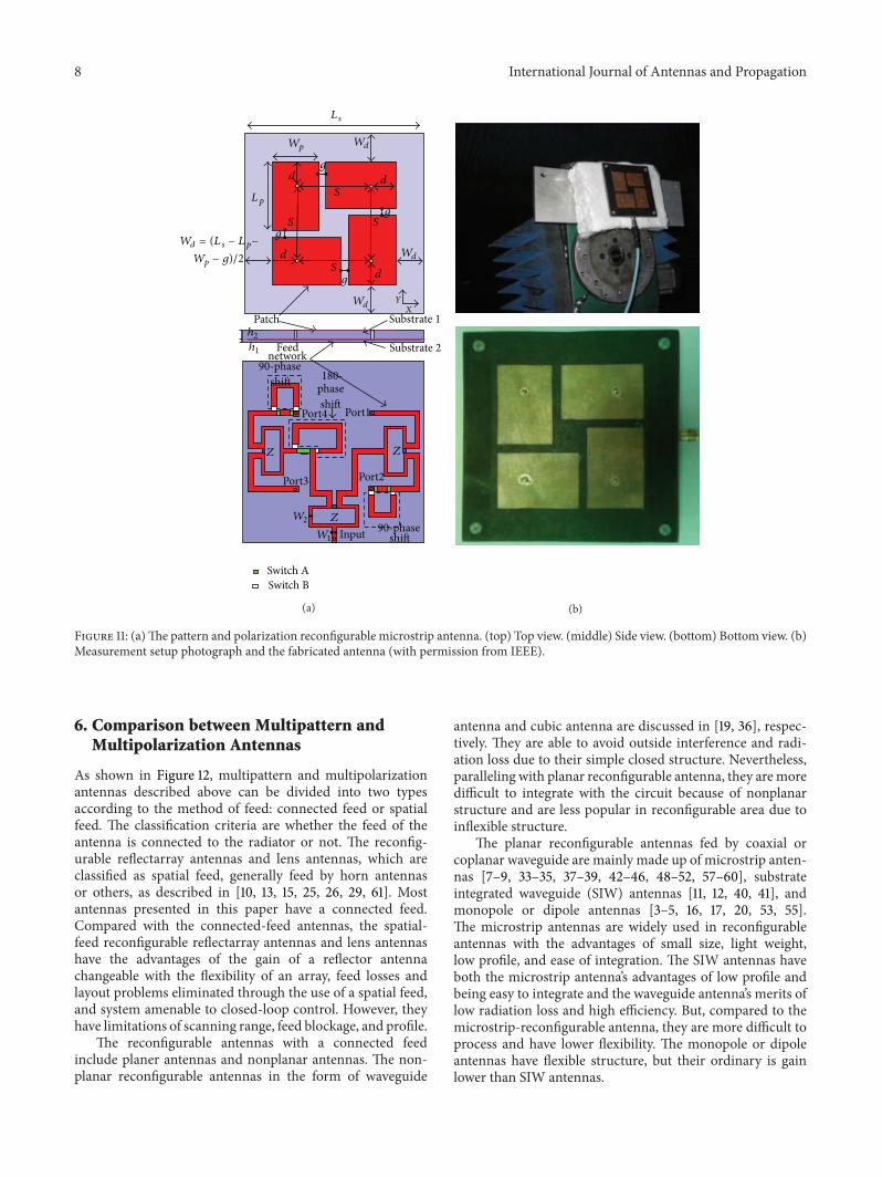
This type of antennas realizes multipattern and multipolar-ization characteristics by using one reconfigurable antenna. Anovel reconfigurable microstrip antenna with radiation pat-tern selectivity and polarization diversity is discussed in [57].As shown in Figure 11(a), A four-way power divider madeby three Wilkinson power dividers and interconnected withswitches (switch A and switch B) is designed to feed-four-rectangular-radiating-patcheantenna. By controlling the stateof the switches, the antenna characteristics can be changedinto two modes. When switch A is closed and switch B isopen, the four rectangular radiating patches are excited byfour sources with equal amplitude and phase. A metama-terial antenna with conical beam and linear polarization isachieved. When switch A is open and switch B is closed,four sources with equal amplitude but 90-phase differencefor each adjacent output lead to a wideband antenna withbroadside beam and circular polarization. The photographsof measurement setup and fabricated antenna are shown inFigure 11(b). This single-port antenna is useful for terrestrialland mobile or other wireless applications.
8 International Journal of Antennas and Propagation
𝐿𝑠
𝑊𝑝 𝑊𝑑
𝑊𝑑
𝑊𝑑
𝐿𝑝
𝑑
𝑑
𝑑
𝑑
𝑔
𝑔
𝑔
𝑔
𝑆
𝑆
𝑆 𝑆
Substrate 1
Substrate 2
𝑊𝑑 = (𝐿 𝑠 − 𝐿𝑝−
𝑊𝑝 − 𝑔)/2
Patch
ℎ1
ℎ2Feed
network90-phase
shift
90-phaseshift
180-phaseshift
Port1Port4
Port3 Port2
Input
Switch ASwitch B
𝑋𝑌
𝑍𝑍
𝑍𝑊2
𝑊1
(a) (b)
Figure 11: (a)The pattern and polarization reconfigurable microstrip antenna. (top) Top view. (middle) Side view. (bottom) Bottom view. (b)Measurement setup photograph and the fabricated antenna (with permission from IEEE).
6. Comparison between Multipattern andMultipolarization Antennas
As shown in Figure 12, multipattern and multipolarizationantennas described above can be divided into two typesaccording to the method of feed: connected feed or spatialfeed. The classification criteria are whether the feed of theantenna is connected to the radiator or not. The reconfig-urable reflectarray antennas and lens antennas, which areclassified as spatial feed, generally feed by horn antennasor others, as described in [10, 13, 15, 25, 26, 29, 61]. Mostantennas presented in this paper have a connected feed.Compared with the connected-feed antennas, the spatial-feed reconfigurable reflectarray antennas and lens antennashave the advantages of the gain of a reflector antennachangeable with the flexibility of an array, feed losses andlayout problems eliminated through the use of a spatial feed,and system amenable to closed-loop control. However, theyhave limitations of scanning range, feed blockage, and profile.
The reconfigurable antennas with a connected feedinclude planer antennas and nonplanar antennas. The non-planar reconfigurable antennas in the form of waveguide
antenna and cubic antenna are discussed in [19, 36], respec-tively. They are able to avoid outside interference and radi-ation loss due to their simple closed structure. Nevertheless,paralleling with planar reconfigurable antenna, they aremoredifficult to integrate with the circuit because of nonplanarstructure and are less popular in reconfigurable area due toinflexible structure.
The planar reconfigurable antennas fed by coaxial orcoplanar waveguide are mainly made up of microstrip anten-nas [7–9, 33–35, 37–39, 42–46, 48–52, 57–60], substrateintegrated waveguide (SIW) antennas [11, 12, 40, 41], andmonopole or dipole antennas [3–5, 16, 17, 20, 53, 55].The microstrip antennas are widely used in reconfigurableantennas with the advantages of small size, light weight,low profile, and ease of integration. The SIW antennas haveboth the microstrip antenna’s advantages of low profile andbeing easy to integrate and the waveguide antenna’s merits oflow radiation loss and high efficiency. But, compared to themicrostrip-reconfigurable antenna, they are more difficult toprocess and have lower flexibility. The monopole or dipoleantennas have flexible structure, but their ordinary is gainlower than SIW antennas.

International Journal of Antennas and Propagation 9
Structures of multi-patternand multi-polarization
antennas
Non-planar
Waveguide/cubic
Spatial feed Connectedfeed
Planar
SIW Microstrip Monopoleor dipole
Reflectarry/lens
Figure 12: The different structures of multipattern and multipolar-ization antennas.
7. Applications
The reconfigurable antennas with multipattern and multipo-larization have been used in both aerospace and terrestrialwireless communication to improve spectrum efficiency,such as wireless systems in dynamic scenarios, adaptive beamscanning, and MIMO systems. In dynamic scenarios, it isnecessary to reconfigure the antenna radiation pattern tomaintain high data rate, serve a new coverage zone, andlimit fading in rainy areas at all possible frequency bandsof operation. The dynamic scenarios including satellite andterminal tracking are discussed in [26, 50, 62–64]. In theadaptive beam scanning system, the antenna should auto-matically change its radiation beam direction correspondingto the various propagation environments or moving target,such as in the system of radar and remote sensing [65–68]. A MIMO system employs multiple antennas at both thetransmitter and receiver front ends. Pattern and polarizationreconfigurable antennas are widely studied and adopted inMIMO systems for their intrinsic pattern and polarizationdiversity advantage in mitigating the multipath fading andincreasing the channel capacity, especially in pattern andpolarization varied environments. The MIMO system withreconfigurable antennas is able to actively manage channelcorrelation, diversity, and interference [9, 17, 18, 27, 31, 59, 69,70].
8. Vision and Goal
Even though the research on the multipattern and multipo-larization antennas has got some achievements, we still have along way to go. Until now, the reconfigurable antennas whichhave been studied and researched are not smart enoughthat they are not completely multifunctional and softwarecontrolled with machine. In addition, the antennas still onlyplay a role of the transducers. A very interesting goal is thatwecan create field programmable antenna system which enjoys
the same flexibility as other field-programmable devices. Inthe field-programmable antenna system, the reconfigurableantennas can detect changes in their RF environment andreact accordingly. If such system is realized, the antennas areevolved from simple transducers to advanced wave proces-sors, along with the advantages of the utilization of radiationpattern selectivity and polarization diversity to transmit overalready “busy” frequencies. And the reconfigurable antennaswill play more a important role in aerospace and terrestrialapplications.
9. Conclusion
This paper presents an overview on the multipattern andmultipolarization antennas. The concepts, characteristics,and typical antennas of radiation patterns and polarizationsare introduced. A comparison between differentmultipatternand multipolarization antennas with different structures andworking mechanisms are also discussed. The reconfigurableantennas can be well applied to dynamic scenarios, adaptivebeam scanning, and MIMO systems. The goal in the futurework is to realize the field programmable antenna system toevolve antennas from simple transducers to advanced waveprocessors.
Acknowledgments
This work was supported in part by the National ScienceFoundation of China and NSAF under their joint Grant no.11076031.
References
[1] D. H. Schaubet, F. G. Farrar, S. T. Hayes et al., “Frequency-agile polarization diverse microstrip antennas and frequencyscanned arrays,” U.S. Patent 4,367,474, Jan. 1983.
[2] C. G. Christodoulou, Y. Tawk, S. A. Lane, and S. R. Erwin,“Reconfigurable antennas for wireless and space applications,”Proceedings of the IEEE, vol. 100, no. 7, pp. 2250–2261, 2012.
[3] W. S. Kang, J. A. Park, and Y. J. Yoon, “Simple reconfigurableantenna with radiation pattern,” Electronics Letters, vol. 44, no.3, pp. 182–183, 2008.
[4] M. I. Lai, T. Y. Wu, J. C. Hsieh, C. H. Wang, and S. K. Jeng,“Design of reconfigurable antennas based on an L-shaped slotand PIN diodes for compact wireless devices,” IET Microwaves,Antennas and Propagation, vol. 3, no. 1, pp. 47–54, 2009.
[5] L. G. Maloratsky, “Switched directional/omnidirectionalantenna module for amplitude monopulse systems,” IEEEAntennas and Propagation Magazine, vol. 51, no. 5, pp. 90–102,2009.
[6] F. Peruani and A. Maiti, “Modeling broadcasting using omni-directional and directional antenna in delay tolerant networksas an epidemic dynamics,” IEEE Journal on Selected Areas inCommunications, vol. 28, no. 4, pp. 524–531, 2010.
[7] M. Ding, R. Jin, J. Geng, X. Guo, and J. Chen, “A high-gaindual-band directional/omnidirectional reconfigurable antennaforWLAN systems,” International Journal of RF andMicrowaveComputer-Aided Engineering, vol. 18, no. 3, pp. 225–232, 2008.
[8] M. Donelli, R. Azaro, L. Fimognari, and A. Massa, “A planarelectronically reconfigurable wi-fi band antenna based on a

10 International Journal of Antennas and Propagation
parasitic microstrip structure,” IEEE Antennas and WirelessPropagation Letters, vol. 6, pp. 623–626, 2007.
[9] D. Piazza, M. D’Amico, and K. R. Dandekar, “Performanceimprovement of a wideband MIMO system by using two-portRLWA,” IEEE Antennas andWireless Propagation Letters, vol. 8,pp. 830–834, 2009.
[10] J. Y. Lau and S. V. Hum, “A planar reconfigurable aperture withlens and reflectarray modes of operation,” IEEE Transactions onMicrowaveTheory and Techniques, vol. 58, no. 12, pp. 3547–3555,2010.
[11] A. Suntives and S. V. Hum, “A fixed-frequency beam-steerablehalf-mode substrate integrated waveguide leaky-wave antenna,”IEEE Transactions on Antennas and Propagation, vol. 60, no. 5,pp. 2540–2544, 2012.
[12] A. Suntives and S. V. Hum, “An electronically tunable half-mode substrate integrated waveguide leaky-wave antenna,” inProceedings of the 5th European Conference on Antennas andPropagation (EUCAP ’11), pp. 3670–3674, April 2011.
[13] C. Liu and S. V. Hum, “An electronically tunable single-layerreflectarray antenna element with improved bandwidth,” IEEEAntennas andWireless Propagation Letters, vol. 9, pp. 1241–1244,2010.
[14] L. Boccia, I. Russo, G. Amendola, and G. Di Massa, “Multi-layer antenna-filter antenna for beam-steering transmit-arrayapplications,” IEEE Transactions on Microwave Theory andTechniques, vol. 60, no. 7, pp. 2287–2300, 2012.
[15] W. Hu, M. Y. Ismail, R. Cahill et al., “Liquid-crystal-basedreflectarray antenna with electronically switchable monopulsepatterns,” Electronics Letters, vol. 43, no. 14, pp. 744–745, 2007.
[16] C. J. Panagamuwa, A. Chauraya, and J. C. Vardaxoglou, “Fre-quency and beam reconfigurable antenna using photoconduct-ing switches,” IEEE Transactions on Antennas and Propagation,vol. 54, no. 2, pp. 449–454, 2006.
[17] D. Piazza, N. J. Kirsch, A. Forenza, R. W. Heath, and K. R.Dandekar, “Design and evaluation of a reconfigurable antennaarray for MIMO systems,” IEEE Transactions on Antennas andPropagation, vol. 56, no. 3, pp. 869–881, 2008.
[18] Z. Li, Z. Du, and K. Gong, “Compact reconfigurable antennaarray for adaptive MIMO systems,” IEEE Antennas andWirelessPropagation Letters, vol. 8, pp. 1317–1320, 2009.
[19] J. Sarrazin, Y. Mahe, S. Avrillon, and S. Toutain, “Patternreconfigurable cubic antenna,” IEEE Transactions on Antennasand Propagation, vol. 57, no. 2, pp. 310–317, 2009.
[20] H. Eslami, C. P. Sukumar, D. Rodrigo et al., “Reduced overheadtraining for multi reconfigurable antennas with beam-tiltingcapability,” IEEE Transactions onWireless Communications, vol.9, no. 12, pp. 3810–3821, 2010.
[21] Y. Yang, X. Zhao, and T.Wang, “Design of arbitrarily controlledmulti-beam antennas via optical transformation,” Journal ofInfrared,Millimeter, and TerahertzWaves, vol. 30, no. 4, pp. 337–348, 2009.
[22] A.-H. Tsai, L.-C. Wang, J.-H. Huang, and R.-B. Hwang, “Stablesubchannel allocation for OFDMA femtocells with switchedmulti-beam directional antennas,” in Proceedings of the IEEEGlobal Telecommunications Conference (GLOBECOM ’11), pp. 1–6, December 2011.
[23] G. Krieger, N. Gebert, and A. Moreira, “Multidimensionalwaveform encoding: a new digital beamforming technique forsynthetic aperture radar remote sensing,” IEEE Transactions onGeoscience and Remote Sensing, vol. 46, no. 1, pp. 31–46, 2008.
[24] G. J. Hayes, J.-H. So, A. Qusba, M. D. Dickey, and G. Lazzi,“Flexible liquid metal alloy (EGaIn) microstrip patch antenna,”IEEE Transactions on Antennas and Propagation, vol. 60, no. 5,pp. 2151–2156, 2012.
[25] M. F. Jamlos, T. A. Rahman, and M. R. Kamarudin, “Theeffects of air stacked on reconfigurable quadratic slots antennafor WiMAX and 4G applications,” Microwave and OpticalTechnology Letters, vol. 54, no. 9, pp. 2139–2144, 2012.
[26] T. Takano, K. Miura, M. Natori et al., “Deployable antenna with10-m maximum diameter for space use,” IEEE Transactions onAntennas and Propagation, vol. 52, no. 1, pp. 2–11, 2004.
[27] Y. Li, Z. Zhang, J. Zheng, and Z. Feng, “Channel capacity studyof polarization reconfigurable slot antenna for indoor MIMOsystem,” Microwave and Optical Technology Letters, vol. 53, no.6, pp. 1209–1213, 2011.
[28] B. Q. Wu and K. M. Luk, “The design of wideband reconfig-urable antenna with four polarizations,” in Proceedings of the39th European Microwave Conference (EuMC ’09), pp. 759–762,September 2009.
[29] A. Clemente, L. Dussopt, R. Sauleau et al., “1-bit reconfigurableunit cell based on PIN diodes for transmit-array applications inX-band,” IEEE Transactions on Antennas and Propagation, vol.60, no. 5, pp. 2260–2269, 2012.
[30] G. Wang, R. Bairavasubramanian, B. Pan, and J.Papapolymerou, “Radiofrequency MEMS-enabledpolarisation-reconfigurable antenna arrays onmultilayer liquidcrystal polymer,” IET Microwave Antenna and Propagation, vol.5, no. 13, pp. 1594–1599, 2011.
[31] A. Grau, J. Romeu, M. J. Lee, S. Blanch, L. Jofre, and F.de Flaviis, “A dual-Linearly-polarized MEMS-reconfigurableantenna for narrowbandMIMOcommunication systems,” IEEETransactions on Antennas and Propagation, vol. 58, no. 1, pp. 4–17, 2010.
[32] P. Seongmin and S. Imseob, “A miniaturized switchable cir-cularly polarized patch antenna controlled by a single diodeoperation,” Microwave and Optical Technology Letters, vol. 54,no. 10, pp. 2375–2378, 2012.
[33] K. F. Tong and J. Huang, “New proximity coupled feedingmethod for reconfigurable circularly polarized microstrip ringantennas,” IEEE Transactions on Antennas and Propagation, vol.56, no. 7, pp. 1860–1866, 2008.
[34] W. S. Yoon, J.W. Baik, H. S. Lee, S. Pyo, S.M.Han, and Y. S. Kim,“A reconfigurable circularly polarizedmicrostrip antennawith aslotted ground plane,” IEEE Antennas and Wireless PropagationLetters, vol. 9, pp. 1161–1164, 2010.
[35] P. Seongmin and S. Youngje, “A circular polarized microstripantenna with an arrow-shaped slotted ground,”Microwave andOptical Technology Letters, vol. 54, no. 1, pp. 271–273, 2012.
[36] J. A. Ruiz-Cruz, M.M. Fahmi, S. A. Fouladi, and R. R.Mansour,“Waveguide antenna feeders with integrated reconfigurabledual circular polarization,” IEEE Transactions on MicrowaveTheory and Techniques, vol. 59, no. 12, pp. 3365–3374, 2011.
[37] S. H. Hsu and K. Chang, “A novel reconfigurable microstripantenna with switchable circular polarization,” IEEE Antennasand Wireless Propagation Letters, vol. 6, pp. 160–162, 2007.
[38] A. Khaleghi and M. Kamyab, “Reconfigurable single portantenna with circular polarization diversity,” IEEE Transactionson Antennas and Propagation, vol. 57, no. 2, pp. 555–559, 2009.
[39] J. S. Row and M. C. Chan, “Reconfigurable circularly-polarizedpatch antenna with conical beam,” IEEE Transactions on Anten-nas and Propagation, vol. 58, no. 8, pp. 2753–2757, 2010.

International Journal of Antennas and Propagation 11
[40] Y. J. Cheng, W. Hong, and K. Wu, “Millimeter-wave half modesubstrate integrated waveguide frequency scanning antennawith quadri-polarization,” IEEE Transactions on Antennas andPropagation, vol. 58, no. 6, pp. 1848–1855, 2010.
[41] Y. Dong and T. Itoh, “Millimeter-Wave half mode substrateintegrated waveguide frequency scanning antenna with quadri-polarization,” IEEE Transactions on Antennas and Propagation,vol. 60, no. 2, pp. 760–771, 2012.
[42] X.-X. Yang, B.-C. Shao, F. Yang et al., “A polarization reconfig-urable patch antenna with loop slots on the ground plane,” IEEEAntennas and Wireless Propagation Letters, vol. 11, pp. 69–72,2012.
[43] Y. F. Wu, C. H. Wu, D. Y. Lai, and F. C. Chen, “A reconfigurablequadri-polarization diversity aperture-coupled patch antenna,”IEEE Transactions on Antennas and Propagation, vol. 55, no. 3,pp. 1009–1012, 2007.
[44] R. H. Chen and J. S. Row, “Single-fed microstrip patch antennawith switchable polarization,” IEEE Transactions on Antennasand Propagation, vol. 56, no. 4, pp. 922–926, 2008.
[45] O. H. Karabey, S. Bildik, and S. Strunck, “Continuously polar-isation reconfigurable antenna element by using liquid crystalbased tunable coupled line,” Electronics Letters, vol. 48, no. 3,pp. 141–143, 2012.
[46] B. Kim, B. Pan, S. Nikolaou, Y. S. Kim, J. Papapolymerou, andM.M. Tentzeris, “A novel single-feed circular microstrip antennawith reconfigurable polarization capability,” IEEE Transactionson Antennas and Propagation, vol. 56, no. 3, pp. 630–638, 2008.
[47] H. Emami, N. Sarkhosh, and E. R. L. Lara, “Reconfigurablephotonic feed for sinuous antenna,” Journal of Light WaveTechnology, vol. 30, no. 16, pp. 2725–2732, 2012.
[48] P. Y. Qin, A. R. Weily, Y. J. Guo, and C. H. Liang, “Polarizationreconfigurable U-slot patch antenna,” IEEE Transactions onAntennas and Propagation, vol. 58, no. 10, pp. 3383–3388, 2010.
[49] M. S. Nishamol, V. P. Sarin, D. Tony et al., “An electronicallyreconfigurable microstrip antenna with switchable slots forpolarization diversity,” IEEE Transactions on Antennas andPropagation, vol. 59, no. 9, pp. 3424–3427, 2011.
[50] J. H. Lim, G. T. Back, and T. Y. Yun, “Polarization-diversitycross-shaped patch antenna for satellite-DMB systems,” ETRIJournal, vol. 32, no. 2, pp. 312–318, 2010.
[51] X. Yuan, Z. Li, D. Rodrigo et al., “A parasitic layer-based recon-figurable antenna design bymulti-objective optimization,” IEEETransactions on Antennas and Propagation, vol. 60, no. 6, pp.2690–2701, 2012.
[52] X.-S. Yang, B.-Z.Wang, S.-H. Yeung et al., “Circularly polarizedreconfigurable crossed-vagi patch antenna,” IEEE Antennas andPropagation Magazine, vol. 53, no. 5, pp. 65–80, 2011.
[53] Y. Dong and T. Itoh, “Planar ultra-wideband antennas in ku-and k-band for pattern or polarization diversity applications,”IEEE Transactions on Antennas and Propagation, vol. 60, no. 6,pp. 2886–2895, 2012.
[54] B. Poussot, J. M. Laheurte, L. Cirio, and O. Picon, “Diversitygainmeasurements of a reconfigurable antenna with switchablepolarization,”Microwave andOptical Technology Letters, vol. 49,no. 12, pp. 3154–3158, 2007.
[55] B. Poussot, J.M. Laheurte, L. Cirio, O. Picon, D. Delcroix, and L.Dussopt, “Diversity measurements of a reconfigurable antennawith switched polarizations and patterns,” IEEE Transactions onAntennas and Propagation, vol. 56, no. 1, pp. 31–38, 2008.
[56] P. Daniele and D. Michele, “Pattern and polarization reconfig-urable CRLH leaky wave antenna,” in Proceedings of the 4th
EuropeanConference onAntennas andPropagation (EuCAP ’10),pp. 1–5, April 2010.
[57] W. Cao, B. Zhang, A. Liu et al., “A reconfigurable microstripantenna with radiation pattern selectivity and polarizationdiversity,” IEEE Antennas and Wireless Propagation Letters, vol.11, pp. 453–456, 2012.
[58] W. Chen, J. Sun, and Z. Feng, “A novel compact reconfigurablepolarization and pattern antenna,” Microwave and OpticalTechnology Letters, vol. 49, no. 11, pp. 2802–2805, 2007.
[59] D. Piazza, P. Mookiah, M. D’Amico, and K. R. Dandekar,“Experimental analysis of pattern and polarization recon-figurable circular patch antennas for MIMO systems,” IEEETransactions on Vehicular Technology, vol. 59, no. 5, pp. 2352–2362, 2010.
[60] W. L. Liu, T. R. Chen, S. H. Chen, and J. S. Row, “Reconfigurablemicrostrip antenna with pattern and polarisation diversities,”Electronics Letters, vol. 43, no. 2, pp. 77–78, 2007.
[61] A. G. Besoli and F. D. Flaviis, “A multifunctional reconfigurablepixeled antenna using mems technology on printed circuitboard,” IEEE Transactions on Antennas and Propagation, vol. 59,no. 12, pp. 4413–4424, 2011.
[62] M. Ali, A. T. M. Sayem, and V. K. Kunda, “A reconfigurablestacked microstrip patch antenna for satellite and terrestriallinks,” IEEE Transactions on Vehicular Technology, vol. 56, no.2, pp. 426–435, 2007.
[63] M. D. van de Burgwal, K. C. Rovers, KC. H. Blom et al.,“Mobile satellite reception with a virtual satellite dish based ona reconfigurable multi-processor architecture,” Microprocessorsand Microsystems, vol. 35, no. 8, pp. 716–728, 2011.
[64] J. A. Lee, S. B. Byun, J. H. Lim, and T. Y. Yun, “Reconfigurableantenna for wideband code division multiple access and koreansatellite digital multimedia broadcasting controlled by PIN-diodes,” Microwave and Optical Technology Letters, vol. 49, no.6, pp. 1334–1337, 2007.
[65] M. Alshershby and J. Q. Lin, “Reconfigurable plasma antennaproduced in air by laser-induced filaments: passive radarapplication,” in Proceedings of the International Conference onOptoelectronics and Microelectronics (ICOM ’12), pp. 364–371,August 2012.
[66] N. Romano, G. Prisco, and F. Soldovieri, “Design of a recon-figurable antenna for ground penetrating radar applications,”Progress in Electromagnetics Research, vol. 94, pp. 1–18, 2009.
[67] F. Soldovieri and N. Romano, “The mutual interaction betweenthe reconfigurable transmitting and receiving antennas inground penetrating radar surveys,” Journal of ElectromagneticWaves and Applications, vol. 23, no. 14-15, pp. 1919–1928, 2009.
[68] M. F. Jamlos, O. A. Aziz, T. A. Rahman et al., “A reconfigurableradial line slot array (RLSA) antenna for beam shape andbroadside application,” Journal of Electromagnetic Waves andApplications, vol. 24, no. 8-9, pp. 1171–1182, 2010.
[69] P. A. Martin, P. J. Smith, and R. Murch, “Improving space-timecode performance in slow fading channels using reconfigurableantennas,” IEEE Communications Letters, vol. 16, no. 4, pp. 494–497, 2012.
[70] F. Fazel, A. Grau, H. Jafarkhani, and F. de Flaviis, “Space-time-state block coded MIMO communication systems usingreconfigurable antennas,” IEEE Transactions on Wireless Com-munications, vol. 8, no. 12, pp. 6019–6029, 2009.

International Journal of
AerospaceEngineeringHindawi Publishing Corporationhttp://www.hindawi.com Volume 2014
RoboticsJournal of
Hindawi Publishing Corporationhttp://www.hindawi.com Volume 2014
Hindawi Publishing Corporationhttp://www.hindawi.com Volume 2014
Active and Passive Electronic Components
Control Scienceand Engineering
Journal of
Hindawi Publishing Corporationhttp://www.hindawi.com Volume 2014
International Journal of
RotatingMachinery
Hindawi Publishing Corporationhttp://www.hindawi.com Volume 2014
Hindawi Publishing Corporation http://www.hindawi.com
Journal ofEngineeringVolume 2014
Submit your manuscripts athttp://www.hindawi.com
VLSI Design
Hindawi Publishing Corporationhttp://www.hindawi.com Volume 2014
Hindawi Publishing Corporationhttp://www.hindawi.com Volume 2014
Shock and Vibration
Hindawi Publishing Corporationhttp://www.hindawi.com Volume 2014
Civil EngineeringAdvances in
Acoustics and VibrationAdvances in
Hindawi Publishing Corporationhttp://www.hindawi.com Volume 2014
Hindawi Publishing Corporationhttp://www.hindawi.com Volume 2014
Electrical and Computer Engineering
Journal of
Advances inOptoElectronics
Hindawi Publishing Corporation http://www.hindawi.com
Volume 2014
The Scientific World JournalHindawi Publishing Corporation http://www.hindawi.com Volume 2014
SensorsJournal of
Hindawi Publishing Corporationhttp://www.hindawi.com Volume 2014
Modelling & Simulation in EngineeringHindawi Publishing Corporation http://www.hindawi.com Volume 2014
Hindawi Publishing Corporationhttp://www.hindawi.com Volume 2014
Chemical EngineeringInternational Journal of Antennas and
Propagation
International Journal of
Hindawi Publishing Corporationhttp://www.hindawi.com Volume 2014
Hindawi Publishing Corporationhttp://www.hindawi.com Volume 2014
Navigation and Observation
International Journal of
Hindawi Publishing Corporationhttp://www.hindawi.com Volume 2014
DistributedSensor Networks
International Journal of