Embed Size (px)
Citation preview

Review for Midterm

Introduction 1-2
Chapter 1Introduction
Computer Networking: A Top Down Approach 6th edition Jim Kurose, Keith RossAddison-WesleyMarch 2012
Slides adopted from original ones provided by the textbook authors.

Introduction
Chapter 1: roadmap1.1 what is the Internet?1.2 network edge
§ end systems, access networks, links1.3 network core
§ packet switching, circuit switching, network structure1.4 delay, loss, throughput in networks1.5 protocol layers, service models1.6 networks under attack: security1.7 history
1-3

Introduction 1-4
Access networks
v DSL: several Mbps, dedicated accessv Cable: tens of Mbps, shared access v Ethernet: up to Gbps, shared access v Wireless: WIFI/cellular, shared access
Keep in mind: v bandwidth (bits per second) of access network?v shared or dedicated?

Introduction 1-5
Physical Media
v guided media § Twisted pair: Ethernet§ Coax: cable networks§ Fiber: optical networks
v unguided media § terrestrial microwave§ LAN (e.g., Wifi)§ wide-area (e.g., cellular)§ satellite

Introduction
Chapter 1: roadmap1.1 what is the Internet?1.2 network edge
§ end systems, access networks, links
1.3 network core§ circuit switching, packet switching, network structure
1.4 delay, loss, throughput in networks1.5 protocol layers, service models1.6 networks under attack: security1.7 history
1-6

Introduction
Circuit switchingend-end resources allocated
to, reserved for “call”between source & dest:
v link bandwidth, switch capacityv dedicated resources: no sharingv circuit-like (guaranteed)
performancev call setup required
v P3
1-7

Introduction 1-8
Network Core: Packet Switching
each end-end data stream divided into packets
v user A, B packets sharenetwork resources
v each packet uses full link bandwidth
v resources used as needed
resource contention: v aggregate resource demand
can exceed amount availablev congestion: packets queue,
wait for link usev store and forward: packets
move one hop at a time
P5 P8

Introduction
Chapter 1: roadmap1.1 what is the Internet?1.2 network edge
§ end systems, access networks, links1.3 network core
§ packet switching, circuit switching, network structure1.4 delay, loss, throughput in networks1.5 protocol layers, service models1.6 networks under attack: security1.7 history
1-9

Introduction 1-10
Nodal delay
v dproc = processing delay§ typically a few microsecs or less
v dqueue = queuing delay§ depends on congestion
v dtrans = transmission delay§ = L/R, significant for low-speed links
v dprop = propagation delay§ a few microsecs to hundreds of msecs
proptransqueueprocnodal ddddd +++=
P10

Introduction 1-11
Other Performance Metrics
v Packet loss: due to buffer overflowv Throughput: data transmission rate, constrained by
bottleneck link

Introduction
Chapter 1: roadmap1.1 what is the Internet?1.2 network edge
§ end systems, access networks, links1.3 network core
§ packet switching, circuit switching, network structure1.4 delay, loss, throughput in networks1.5 protocol layers, service models1.6 networks under attack: security1.7 history
1-12

Introduction
Internet protocol stackv application: supporting network
applications§ FTP, SMTP, HTTP
v transport: process-process data transfer§ TCP, UDP
v network: routing of datagrams from source to destination§ IP, routing protocols
v link: data transfer between neighboring network elements§ Ethernet, 802.11 (WiFi), PPP
v physical: bits “on the wire”
application
transport
network
link
physical
1-13

Application Layer 2-14
Chapter 2Application Layer
Computer Networking: A Top Down Approach 6th edition Jim Kurose, Keith RossAddison-WesleyMarch 2012
Slides adopted from original ones provided by the textbook authors.

Application Layer 2-15
Chapter 2: outline
2.1 Principles of network applications
2.2 Web and HTTP2.3 FTP 2.4 Electronic mail
§ SMTP, POP3, IMAP2.5 DNS
2.6 P2P applications2.7 Socket programming
with UDP and TCP

16
Application architectures
v Client-server§ Always-on server, intermittently connected client.§ Servers are bottlenecks.
v Peer-to-peer (P2P)§ Peers intermittently connected. § Highly scalable but difficult to manage.
Application Layer 2-

Application Layer 2-17
Internet transport protocols services
TCP service:v reliable transport between
sending and receiving process
v flow control: sender won’t overwhelm receiver
v congestion control: throttle sender when network overloaded
v does not provide: timing, minimum throughput guarantee, security
v connection-oriented: setup required between client and server processes
UDP service:v unreliable data transfer
between sending and receiving process
v does not provide:reliability, flow control, congestion control, timing, throughput guarantee, security, orconnection setup,

Application Layer 2-18
Chapter 2: outline
2.1 principles of network applications§ app architectures§ app requirements
2.2 Web and HTTP (P4 P7 P8 P9)
2.3 FTP
2.4 electronic mail§ SMTP, POP3, IMAP
2.5 DNS2.6 P2P applications (P22
P26)
Basic info and techniques of each protocol. No programming questions.

Transport Layer 3-19
Chapter 3Transport Layer
Computer Networking: A Top Down Approach
6th edition Jim Kurose, Keith Ross
Addison-WesleyMarch 2012
Slides adopted from original ones provided by the textbook authors.

Transport Layer 3-20
Chapter 3 outline
3.1 transport-layer services
3.2 multiplexing and demultiplexing
3.3 connectionless transport: UDP
3.4 principles of reliable data transfer
3.5 connection-oriented transport: TCP§ segment structure§ reliable data transfer§ flow control§ connection management
3.6 principles of congestion control
3.7 TCP congestion control

Transport Layer 3-21
Transport vs. network layer
v network layer: logical communication between hostsv transport layer: logical communication between
processes § relies on, enhances, network layer services
v two transport-layer protocols§ reliable, in-order delivery: TCP§ unreliable, unordered delivery: UDP

Transport Layer 3-22
Chapter 3 outline
3.1 transport-layer services
3.2 multiplexing and demultiplexing
3.3 connectionless transport: UDP
3.4 principles of reliable data transfer
3.5 connection-oriented transport: TCP§ segment structure§ reliable data transfer§ flow control§ connection management
3.6 principles of congestion control
3.7 TCP congestion control

Transport Layer 3-23
Demultiplexing
v UDP socket identified by 2-tuple:§ dest IP address§ dest port number
v TCP socket identified by 4-tuple: § source IP address§ source port number§ dest IP address§ dest port number

Transport Layer 3-24
Chapter 3 outline
3.1 transport-layer services
3.2 multiplexing and demultiplexing
3.3 connectionless transport: UDP
3.4 principles of reliable data transfer
3.5 connection-oriented transport: TCP§ segment structure§ reliable data transfer§ flow control§ connection management
3.6 principles of congestion control
3.7 TCP congestion control

Transport Layer 3-25
UDP: User Datagram Protocol [RFC 768]
v “best effort” service, UDP segments may be:§ lost§ delivered out-of-order
to appv connectionless:
§ no handshaking between UDP sender, receiver
§ each UDP segment handled independently of others
source port # dest port #
32 bits
applicationdata
(payload)
UDP segment format
length checksum

Transport Layer 3-26
Internet checksum (P4)
1 1 1 1 0 0 1 1 0 0 1 1 0 0 1 1 01 1 1 0 1 0 1 0 1 0 1 0 1 0 1 0 1
1 1 0 1 1 1 0 1 1 1 0 1 1 1 0 1 1
1 1 0 1 1 1 0 1 1 1 0 1 1 1 1 0 01 0 1 0 0 0 1 0 0 0 1 0 0 0 0 1 1
wraparound
sumchecksum
v Goal: detect “errors” (e.g., flipped bits) in transmitted segment
v When adding numbers, a carryout from the most significant bit needs to be added to the result
v checksum: 1s compliment of sum

Transport Layer 3-27
Chapter 3 outline
3.1 transport-layer services
3.2 multiplexing and demultiplexing
3.3 connectionless transport: UDP
3.4 principles of reliable data transfer
3.5 connection-oriented transport: TCP§ segment structure§ reliable data transfer§ flow control§ connection management
3.6 principles of congestion control
3.7 TCP congestion control
Transport Layer 3-28
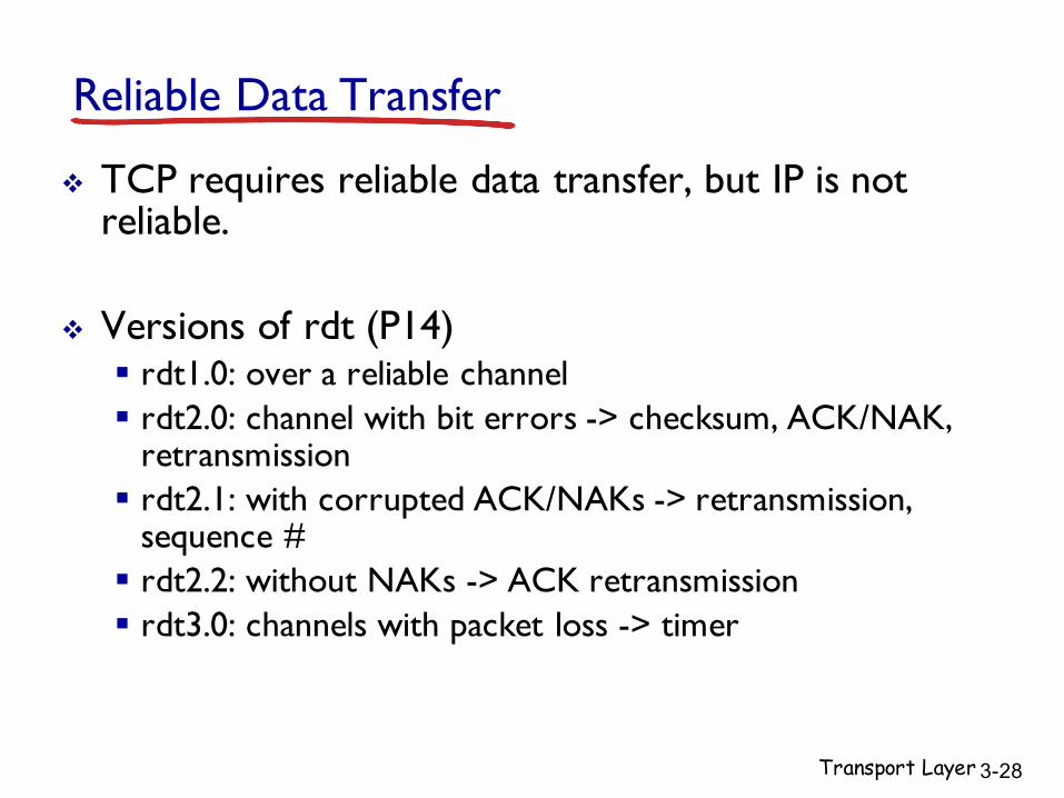
Reliable Data Transfer
v TCP requires reliable data transfer, but IP is not reliable.
v Versions of rdt (P14)§ rdt1.0: over a reliable channel§ rdt2.0: channel with bit errors -> checksum, ACK/NAK,
retransmission§ rdt2.1: with corrupted ACK/NAKs -> retransmission,
sequence #§ rdt2.2: without NAKs -> ACK retransmission§ rdt3.0: channels with packet loss -> timer

Transport Layer 3-29
Pipelined protocols (P23, P24)v increased utilization:v go-Back-N
§ always send ACK for correctly-received pkt with highest in-order seq #
§ timeout(n): retransmit pkt n and all higher seq # pkts in window
§ seq # size = window size + 1v selective repeat
§ receiver individually acknowledges all correctly received pkts§ timeout(n): sender only resends pkts for which ACK not
received§ seq # size = window size * 2
U sender =
n L / R RR RTT + L / R

Transport Layer 3-30
Chapter 3 outline
3.1 transport-layer services
3.2 multiplexing and demultiplexing
3.3 connectionless transport: UDP
3.4 principles of reliable data transfer
3.5 connection-oriented transport: TCP§ segment structure§ reliable data transfer§ flow control§ connection management
3.6 principles of congestion control
3.7 TCP congestion control

Transport Layer 3-31
TCP segment structure
source port # dest port #
32 bits
applicationdata
(variable length)
sequence numberacknowledgement number
receive window
Urg data pointerchecksumFSRPAUhead
lennot
used
options (variable length)
URG: urgent data (generally not used)
ACK: ACK #valid
PSH: push data now(generally not used)
RST, SYN, FIN:connection estab(setup, teardown
commands)
# bytes rcvr willingto accept
countingby bytes of data(not segments!)
Internetchecksum
(as in UDP)

Maximum segment size (MSS)
v MSS: maximum bytes of TCP payloadv Sequence #: byte-stream # of first byte in
segmentv E.g. file size 500,000 bytes, MSS 1,000 bytes
Transport Layer 3-32

Transport Layer 3-33
TCP seq. #’s and ACKs (P27)
Seq. #’s:§ byte stream “number” of first byte in segment’s data
ACKs:§ seq # of next byte expected from other side§ cumulative ACK
Setting the time out§ TimeoutInterval = EstimatedRTT + 4*DevRTT§ EstimatedRTT = (1- α)*EstimatedRTT + α*SampleRTT§ DevRTT = (1-β)*DevRTT + β*|SampleRTT-EstimatedRTT|

Transport Layer 3-34
Chapter 3 outline
3.1 transport-layer services
3.2 multiplexing and demultiplexing
3.3 connectionless transport: UDP
3.4 principles of reliable data transfer
3.5 connection-oriented transport: TCP§ segment structure§ reliable data transfer§ flow control§ connection management
3.6 principles of congestion control
3.7 TCP congestion control

Transport Layer 3-35
TCP sender events:data rcvd from app:v create segment with
seq #v seq # is byte-stream
number of first data byte in segment
v start timer if not already running § think of timer as for
oldest unacked segment
§ expiration interval: TimeOutInterval
timeout:v retransmit segment
that caused timeoutv restart timerack rcvd:v if ack acknowledges
previously unacked segments§ update ACK status§ start timer if there are
still unacked segments§ triple duplicate ACKs:
retransmit

Transport Layer 3-36
TCP receiver events
event at receiver
arrival of in-order segment withexpected seq #. All data up toexpected seq # already ACKed
arrival of in-order segment withexpected seq #. One other segment has ACK pending
arrival of out-of-order segmenthigher-than-expect seq. # .Gap detected
arrival of segment that partially or completely fills gap
TCP receiver action
delayed ACK. Wait up to 500msfor next segment. If no next segment,send ACK
immediately send single cumulative ACK, ACKing both in-order segments
immediately send duplicate ACK,indicating seq. # of next expected byte
immediate send ACK, provided thatsegment starts at lower end of gap

Transport Layer 3-37
Chapter 3 outline
3.1 transport-layer services
3.2 multiplexing and demultiplexing
3.3 connectionless transport: UDP
3.4 principles of reliable data transfer
3.5 connection-oriented transport: TCP§ segment structure§ reliable data transfer§ flow control§ connection management
3.6 principles of congestion control
3.7 TCP congestion control

Transport Layer 3-38
TCP flow control
buffered data
free buffer spacerwnd
RcvBuffer
TCP segment payloads
to application processv receiver “advertises” free
buffer space by including rwnd value in TCP header of receiver-to-sender segments§ RcvBuffer size set via
socket options (typical default is 4096 bytes)
§ many operating systems autoadjust RcvBuffer
v sender limits amount of unacked (“in-flight”) data to receiver’s rwnd value
v guarantees receive buffer will not overflow
receiver-side buffering

Transport Layer 3-39
Chapter 3 outline
3.1 transport-layer services
3.2 multiplexing and demultiplexing
3.3 connectionless transport: UDP
3.4 principles of reliable data transfer
3.5 connection-oriented transport: TCP§ segment structure§ reliable data transfer§ flow control§ connection management
3.6 principles of congestion control
3.7 TCP congestion control

Transport Layer 3-40
TCP 3-way handshake
SYNbit=1, Seq=x
choose init seq num, xsend TCP SYN msg
ESTAB
SYNbit=1, Seq=yACKbit=1; ACKnum=x+1
choose init seq num, ysend TCP SYNACKmsg, acking SYN
ACKbit=1, ACKnum=y+1
received SYNACK(x) indicates server is live;send ACK for SYNACK;
this segment may contain client-to-server data received ACK(y)
indicates client is live
SYNSENT
ESTAB
SYN RCVD
client state
LISTENserver state
LISTEN

Transport Layer 3-41
FIN_WAIT_2
CLOSE_WAIT
FINbit=1, seq=y
ACKbit=1; ACKnum=y+1
ACKbit=1; ACKnum=x+1wait for server
close
can stillsend data
can no longersend data
LAST_ACK
CLOSED
TIMED_WAIT
timed wait for 2*max
segment lifetime
CLOSED
TCP: closing a connection
FIN_WAIT_1 FINbit=1, seq=xcan no longersend but canreceive data
clientSocket.close()
client state server state
ESTABESTAB

Transport Layer 3-42
Chapter 3 outline
3.1 transport-layer services
3.2 multiplexing and demultiplexing
3.3 connectionless transport: UDP
3.4 principles of reliable data transfer
3.5 connection-oriented transport: TCP§ segment structure§ reliable data transfer§ flow control§ connection management
3.6 principles of congestion control
3.7 TCP congestion control

Transport Layer 3-43
Approaches towards congestion control
two broad approaches towards congestion control:
end-end congestion control:
v no explicit feedback from network
v congestion inferred from end-system observed loss, delay
v approach taken by TCP
network-assisted congestion control:
v routers provide feedback to end systems§ single bit indicating
congestion (SNA, DECbit, TCP/IP ECN, ATM)
§explicit rate for sender to send at

Transport Layer 3-44
Chapter 3 outline
3.1 transport-layer services
3.2 multiplexing and demultiplexing
3.3 connectionless transport: UDP
3.4 principles of reliable data transfer
3.5 connection-oriented transport: TCP§ segment structure§ reliable data transfer§ flow control§ connection management
3.6 principles of congestion control
3.7 TCP congestion control

Transport Layer 3-45
Summary: TCP Congestion Control (P40, P46)
v when cwnd < ssthresh, sender in slow-start phase, window grows exponentially.
v when cwnd >= ssthresh, sender is in congestion-avoidance phase, window grows linearly.
v when triple duplicate ACK occurs, ssthresh set to cwnd/2, cwnd set to ssthresh+3
v when timeout occurs, ssthresh set to cwnd/2, cwnd set to 1 MSS.

Transport Layer 3-46
fairness goal: if K TCP sessions share same bottleneck link of bandwidth R, each should have average rate of R/K
TCP connection 1
bottleneckrouter
capacity R
TCP Fairness
TCP connection 2

Chapter 4Network Layer
Computer Networking: A Top Down Approach
6th edition Jim Kurose, Keith Ross
Addison-WesleyMarch 2012
Network Layer 4-47
Slides adopted from original ones provided by the textbook authors.

Network Layer 4-48
Chapter 4: network layer
chapter goals:v understand principles behind network layer
services:§ network layer service models§ forwarding versus routing§ how a router works§ routing (path selection)§ broadcast, multicast
v instantiation, implementation in the Internet

Network Layer 4-49
4.1 introduction4.2 virtual circuit and
datagram networks4.3 what’s inside a router4.4 IP: Internet Protocol
§ datagram format§ IPv4 addressing§ ICMP§ IPv6
4.5 routing algorithms§ link state§ distance vector§ hierarchical routing
4.6 routing in the Internet§ RIP§ OSPF§ BGP
4.7 broadcast and multicast routing
Chapter 4: outline

Network Layer 4-50
Network layerv transport segment from
sending to receiving host v on sending side
encapsulates segments into datagrams
v on receiving side, delivers segments to transport layer
v network layer protocols in every host, router
v router examines header fields in all IP datagrams passing through it
applicationtransportnetworkdata linkphysical
applicationtransportnetworkdata linkphysical
networkdata linkphysical network
data linkphysical
networkdata linkphysical
networkdata linkphysical
networkdata linkphysical
networkdata linkphysical
networkdata linkphysical
networkdata linkphysical
networkdata linkphysical
networkdata linkphysicalnetwork
data linkphysical

Network Layer 4-51
Two key network-layer functions
v forwarding: move packets from router’s input to appropriate router output
v routing: determine route taken by packets from source to dest.
§ routing algorithms
analogy:
v routing: process of planning trip from source to dest
v forwarding: process of getting through single interchange
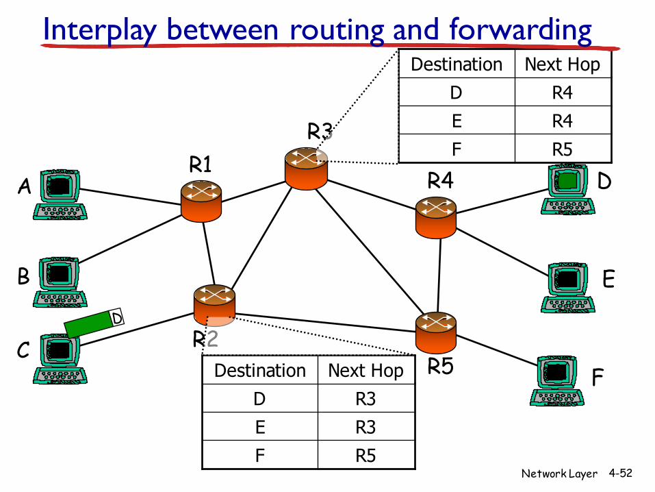
Network Layer 4-52
R3
A
B
C
R1
R2
R4 D
E
FR5
R5FR3ER3D
Next HopDestination
R5FR4ER4D
Next HopDestinationInterplay between routing and forwarding

Network Layer 4-53
1
23
0111
value in arrivingpacket’s header
routing algorithm
local forwarding tableheader value output link
0100010101111001
3221
Interplay between routing and forwarding
routing algorithm determinesend-end-path through network
forwarding table determineslocal forwarding at this router

Network Layer 4-54
Connection setup
v 3rd important function in some network architectures:§ ATM, frame relay, X.25
v before datagrams flow, two end hosts andintervening routers establish virtual connection§ routers get involved
v network vs transport layer connection service:§ network: between two hosts (may also involve intervening
routers in case of VCs)§ transport: between two processes

Network Layer 4-55
Network service modelQ: What service model for “channel” transporting datagrams from sender to receiver?
example services for individual datagrams:
v guaranteed deliveryv guaranteed delivery with
less than 40 msec delay
example services for a flow of datagrams:
v in-order datagram delivery
v guaranteed minimum bandwidth to flow
v restrictions on changes in inter-packet spacing

Network Layer 4-56
Network layer service models:
NetworkArchitecture
Internet
ATM
ATM
ATM
ATM
ServiceModel
best effort
CBR
VBR
ABR
UBR
Bandwidth
none
constantrateguaranteedrateguaranteed minimumnone
Loss
no
yes
yes
no
no
Order
no
yes
yes
yes
yes
Timing
no
yes
yes
no
no
Congestionfeedback
no (inferredvia loss)nocongestionnocongestionyes
no
Guarantees ?

Network Layer 4-57
4.1 introduction4.2 virtual circuit and
datagram networks4.3 what’s inside a router4.4 IP: Internet Protocol
§ datagram format§ IPv4 addressing§ ICMP§ IPv6
4.5 routing algorithms§ link state§ distance vector§ hierarchical routing
4.6 routing in the Internet§ RIP§ OSPF§ BGP
4.7 broadcast and multicast routing
Chapter 4: outline

Network Layer 4-58
Connection, connection-less service
v datagram network provides network-layer connectionless service
v virtual-circuit network provides network-layer connection service
v analogous to TCP/UDP connecton-oriented / connectionless transport-layer services, but:§ service: host-to-host§ no choice: network provides one or the other§ implementation: in network core

Network Layer 4-59
Virtual circuits
v call setup, teardown for each call before data can flowv each packet carries VC identifier (not destination host
address)v every router on source-dest path maintains “state” for
each passing connectionv link, router resources (bandwidth, buffers) may be
allocated to VC (dedicated resources = predictable service)
“source-to-dest path behaves much like telephone circuit”§ performance-wise§ network actions along source-to-dest path

Network Layer 4-60
VC implementation
a VC consists of:1. path from source to destination2. VC numbers, one number for each link along path3. entries in forwarding tables in routers along path
v packet belonging to VC carries VC number (rather than dest address)
v VC number can be changed on each link.§ new VC number comes from forwarding table

Network Layer 4-61
VC forwarding table12 22 32
1 23
VC numberinterfacenumber
Incoming interface Incoming VC # Outgoing interface Outgoing VC #
1 12 3 222 63 1 18 3 7 2 171 97 3 87… … … …
forwarding table innorthwest router:
VC routers maintain connection state information!

Network Layer 4-62
applicationtransportnetworkdata linkphysical
Virtual circuits: signaling protocols
v used to setup, maintain teardown VCv used in ATM, frame-relay, X.25v not used in today’s Internet
1. initiate call 2. incoming call3. accept call4. call connected
5. data flow begins 6. receive dataapplicationtransportnetworkdata linkphysical

Network Layer 4-63
Datagram networksv no call setup at network layerv routers: no state about end-to-end connections
§ no network-level concept of “connection”v packets forwarded using destination host address
1. send datagrams
applicationtransportnetworkdata linkphysical
applicationtransportnetworkdata linkphysical
2. receive datagrams

Network Layer 4-64
1
23
Datagram forwarding table
IP destination address in arriving packet’s header
routing algorithm
local forwarding tabledest address output link
address-range 1address-range 2address-range 3address-range 4
3221
4 billion IP addresses, so rather than list individual destination addresslist range of addresses(aggregate table entries)

Network Layer 4-65
Destination Address Range
11001000 00010111 00010000 00000000through11001000 00010111 00010111 11111111
11001000 00010111 00011000 00000000through11001000 00010111 00011000 11111111
11001000 00010111 00011001 00000000through11001000 00010111 00011111 11111111
otherwise
Link Interface
0
1
2
3
Q: but what happens if ranges don’t divide up so nicely?
Datagram forwarding table

Network Layer 4-66
Longest prefix matching
Destination Address Range
11001000 00010111 00010*** *********
11001000 00010111 00011000 *********
11001000 00010111 00011*** *********
otherwise
DA: 11001000 00010111 00011000 10101010
examples:DA: 11001000 00010111 00010110 10100001 which interface?
which interface?
longest prefix matching
Link interface
0
1
2
3
when looking for forwarding table entry for given destination address, use longest address prefix that matches destination address.

Example
v Consider a datagram network using 8-bit host addresses. Suppose a router uses longest prefix matching and has the following forwarding table:
v For each of the interfaces, give the associated range of destination host addresses and the number of addresses in the range.
Network Layer 4-67
Prefix Match Interface00 001 1011 2


![2toxico-overdose-lec07-1223099219105884-9-101219081153-phpapp02 [Compatibility Mode]](https://img.pdfslide.net/doc/110x75/55cf8e01550346703b8d85a0/2toxico-overdose-lec07-1223099219105884-9-101219081153-phpapp02-compatibility.jpg)