Embed Size (px)
Citation preview
Fuel Processing Technology 88 (2007) 3–22www.elsevier.com/locate/fuproc
Review
Integrated fuel processors for fuel cell application: A review
Aidu Qi a,b, Brant Peppley a,b, Kunal Karan a,c,⁎
a Queen's-RMC Fuel Cell Research Center, Kingston, Ont., Canada K7L 5L9b Department of Chemistry and Chemical Engineering, Royal Military College of Canada, Kingston, Ont., Canada K7K 7B4
c Department of Chemical Engineering, Queen's University, Kingston, Ont., Canada K7L 3N6
Accepted 26 May 2006
Abstract
This report documents the key technological progress made over last two decades in the field of development of integrated fuel processor forhydrogen generation. Studies on process optimization based on numerical simulation/calculation, mass and energy management, parametricadjustment have been reported. A number of these studies discuss the application of reforming process assisted by other technologies such as pressureswing adsorption and membrane separation to enhance the hydrogen productivity and/or purity. However, for such systems the extent of integrationamong and between components remains limited. Accordingly, the net efficiency is compromised due to the mass/heat transfer rate and reactiondynamics either in the individual units or the complete system. Process intensification technologies such as engineered catalysts, on-site heatproduction/removal and product purification can not only allow precise control of reaction and heat/mass transfer rates, but also help optimize theoperation conditions, and, consequently, improve overall efficiency and mitigate the requirement for materials and capital investment. It seems thatmicro-scale technologies, possessing the typical characteristics of process intensification technologies, have potential for making the integrated fuelprocessor into practice.© 2006 Elsevier B.V. All rights reserved.
Keywords: Fuel processor; Hydrogen generation; Fuel cell; Balance of plant; Process intensification; Process optimization; Micro-scale technologies
Contents
1. Introduction . . . . . . . . . . . . . . . . . . . . . . . . . . . . . . . . . . . . . . . . . . . . . . . . . . . . . . . . . . . . . . . . 52. Process optimization: thermodynamic analysis . . . . . . . . . . . . . . . . . . . . . . . . . . . . . . . . . . . . . . . . . . . . . . 5
2.1. Fuel types . . . . . . . . . . . . . . . . . . . . . . . . . . . . . . . . . . . . . . . . . . . . . . . . . . . . . . . . . . . . . 52.2. Reforming processes. . . . . . . . . . . . . . . . . . . . . . . . . . . . . . . . . . . . . . . . . . . . . . . . . . . . . . . . 7
2.2.1. Conventional reforming processes (external reforming) . . . . . . . . . . . . . . . . . . . . . . . . . . . . . . . . . 72.2.2. Internal reforming (integration of reformer with the FC). . . . . . . . . . . . . . . . . . . . . . . . . . . . . . . . 12
2.3. Mass and energy management. . . . . . . . . . . . . . . . . . . . . . . . . . . . . . . . . . . . . . . . . . . . . . . . . . 132.3.1. Mass management . . . . . . . . . . . . . . . . . . . . . . . . . . . . . . . . . . . . . . . . . . . . . . . . . . . 132.3.2. Thermal management. . . . . . . . . . . . . . . . . . . . . . . . . . . . . . . . . . . . . . . . . . . . . . . . . . 13
2.4. Balance of plant . . . . . . . . . . . . . . . . . . . . . . . . . . . . . . . . . . . . . . . . . . . . . . . . . . . . . . . . . 153. Process intensification: dynamic enhancement . . . . . . . . . . . . . . . . . . . . . . . . . . . . . . . . . . . . . . . . . . . . . 15
3.1. Engineered catalyst and desulfurizer . . . . . . . . . . . . . . . . . . . . . . . . . . . . . . . . . . . . . . . . . . . . . . 163.2. Membrane-assisted reforming . . . . . . . . . . . . . . . . . . . . . . . . . . . . . . . . . . . . . . . . . . . . . . . . . . 16
3.2.1. Oxygen ion transport membranes (ITMs) . . . . . . . . . . . . . . . . . . . . . . . . . . . . . . . . . . . . . . . 163.2.2. H2-permeable membrane (HPM)-assisted reforming . . . . . . . . . . . . . . . . . . . . . . . . . . . . . . . . . . 18
⁎ Corresponding author. Department of Chemical Engineering, Queen's University, Kingston, Ont., Canada K7L 3N6. Tel.: +1 613 533 3095; fax: +1 613 533 6637.E-mail address: [email protected] (K. Karan).
0378-3820/$ - see front matter © 2006 Elsevier B.V. All rights reserved.doi:10.1016/j.fuproc.2006.05.007
4 A. Qi et al. / Fuel Processing Technology 88 (2007) 3–22
3.3. Micro-technologies . . . . . . . . . . . . . . . . . . . . . . . . . . . . . . . . . . . . . . . . . . . . . . . . . . . . . . . 183.3.1. Combustion and SR coupling . . . . . . . . . . . . . . . . . . . . . . . . . . . . . . . . . . . . . . . . . . . . . 183.3.2. Combustion/vaporization integration . . . . . . . . . . . . . . . . . . . . . . . . . . . . . . . . . . . . . . . . . 193.3.3. Water gas shift (WGS) unit . . . . . . . . . . . . . . . . . . . . . . . . . . . . . . . . . . . . . . . . . . . . . . 193.3.4. Preferential oxidation (PROX) unit . . . . . . . . . . . . . . . . . . . . . . . . . . . . . . . . . . . . . . . . . . 193.3.5. Fully integrated fuel processor . . . . . . . . . . . . . . . . . . . . . . . . . . . . . . . . . . . . . . . . . . . . 20
4. Conclusion and outlook . . . . . . . . . . . . . . . . . . . . . . . . . . . . . . . . . . . . . . . . . . . . . . . . . . . . . . . . 20References . . . . . . . . . . . . . . . . . . . . . . . . . . . . . . . . . . . . . . . . . . . . . . . . . . . . . . . . . . . . . . . . . 20
Nomenclature
H enthalpy, kJ/moly oxygen/fuel ratio in the overall reactionY yield for hydrogen, mol/mol C
Subscriptc combustionf formationm hydrogen atom number in CnHmOz
n carbon atom number in CnHmOz
z oxygen atom number in CnHmOz
Greek lettersα a kind of structure for Al2O3
Δ change in a propertyη efficiency of the fuel processorθ general temperature and pressure
AcronymsACR Autothermal Cyclic ReformingANL Argonne National LaboratoryATR Autothermal ReformingCPO Catalytic Partial OxidationCVD Chemical Vapor DepositionDOE Department of Energy (USA)FC Fuel CellGM General MotorHBT Hydrogen Burner TechnologyHPM Hydrogen-permeable MembraneHTM Hydrogen Transport MembraneHT-WGS High-temperature Water Gas ShiftINEL Idaho National Engineering and Environmental LaboratoryITM Ion Transport MembraneJM Johnson MattheyLHV Lower Heating ValueLPG Liquid Petroleum GasLT-WGS Low-temperature Water Gas ShiftMCFC Molten Carbonate Fuel CellMON Motor Octane NumberNG Natural GasOTM Oxygen Transport MembranePEMFC Polymer Electrolyte Membrane Fuel CellPNNL Pacific Northwest National LaboratoryPOX Partial Oxidation
PROX Preferential OxidationPSA Pressure Swing AdsorptionPSR Pressure Swing Reforming(er)PSU Pennsylvania State UniversityR&D Research and DevelopmentRMC Royal Military College of CanadaRON Research Octane NumberSOFC Solid Oxide Fuel CellSR Steam ReformingSS Stainless SteelWGS Water Gas Shift
5A. Qi et al. / Fuel Processing Technology 88 (2007) 3–22
1. Introduction
The incentive to produce hydrogen/syngas preferably, but notnecessarily, for fuel cells in the stationary and auxiliary powerunits sparked the R&D of small/medium-scale fuel processingsystem [1–3]. However, the current industrial hydrogenproduction technology could only partially meet the requirementof the small-scale fuel processors, which must be compact,turnkey and of high efficiency by combining component func-tionalities and eliminating unnecessary components. Althoughthe on-board fuel processor program has been put on hold by theU.S. Department of Energy (DOE), a number of new approachesfor the establishment of hydrogen refueling station based onsome form of a fuel processor are being pursued [2].
In this paper, various approaches to hydrogen production infuel processors are reviewed. In addition, methods for maxi-mizing the efficiency of fuel processor system, technical feasi-bility of the whole fuel processor, compactness of the system aswell as system dynamics are discussed. Recent progress made inthe field of process optimization and process intensificationrelated to fuel processors is also addressed. It should be notedthat new approaches such as photo-biological and photo-electrochemical methods with potential for hydrogen productionin future, are beyond the scope of this review. This paper dealswith the reforming process including autothermal reforming
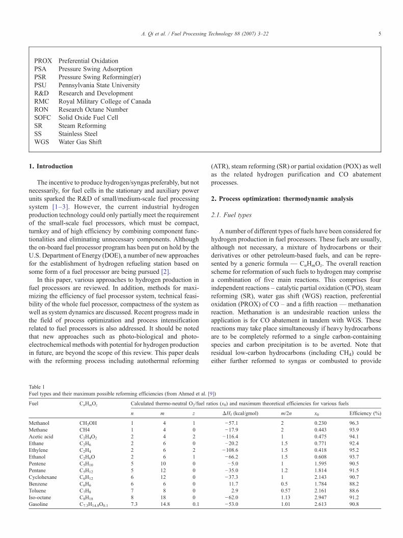
Table 1Fuel types and their maximum possible reforming efficiencies (from Ahmed et al. [
Fuel CnHmOz Calculated thermo-neutral O2/fuel ra
n m z
Methanol CH3OH 1 4 1Methane CH4 1 4 0Acetic acid C2H4O2 2 4 2Ethane C2H6 2 6 0Ethylene C2H4 2 6 2Ethanol C2H6O 2 6 1Pentene C5H10 5 10 0Pentane C5H12 5 12 0Cyclohexane C6H12 6 12 0Benzene C6H6 6 6 0Toluene C7H8 7 8 0Iso-octane C8H18 8 18 0Gasoline C7.3H14.8O0.1 7.3 14.8 0.1
(ATR), steam reforming (SR) or partial oxidation (POX) as wellas the related hydrogen purification and CO abatementprocesses.
2. Process optimization: thermodynamic analysis
2.1. Fuel types
A number of different types of fuels have been considered forhydrogen production in fuel processors. These fuels are usually,although not necessary, a mixture of hydrocarbons or theirderivatives or other petroleum-based fuels, and can be repre-sented by a generic formula — CnHmOz. The overall reactionscheme for reformation of such fuels to hydrogen may comprisea combination of five main reactions. This comprises fourindependent reactions – catalytic partial oxidation (CPO), steamreforming (SR), water gas shift (WGS) reaction, preferentialoxidation (PROX) of CO – and a fifth reaction — methanationreaction. Methanation is an undesirable reaction unless theapplication is for CO abatement in tandem with WGS. Thesereactions may take place simultaneously if heavy hydrocarbonsare to be completely reformed to a single carbon-containingspecies and carbon precipitation is to be averted. Note thatresidual low-carbon hydrocarbons (including CH4) could beeither further reformed to syngas or combusted to provide
9])
tios (x0) and maximum theoretical efficiencies for various fuels
ΔHf (kcal/gmol) m/2n x0 Efficiency (%)
−57.1 2 0.230 96.3−17.9 2 0.443 93.9−116.4 1 0.475 94.1−20.2 1.5 0.771 92.4−108.6 1.5 0.418 95.2−66.2 1.5 0.608 93.7−5.0 1 1.595 90.5−35.0 1.2 1.814 91.5−37.3 1 2.143 90.711.7 0.5 1.784 88.22.9 0.57 2.161 88.6
−62.0 1.13 2.947 91.2−53.0 1.01 2.613 90.8
6 A. Qi et al. / Fuel Processing Technology 88 (2007) 3–22
energy, and CO can be converted to CO2 while producing extraamount of H2 by WGS. Thus the overall reforming reaction canbe written as follows (Eq. (1)):
CnHmOz þ yðO2 þ 3:76N2Þ þ 2 n−y−z2
� �H2OYnCO2
þ 2 n−y−z2þ m
4
� �H2 þ 3:76yN2 ð1Þ
It should be noted that the expression for the overall reaction(fuel→H2) is always an appropriate representation of the over-all fuel processing reaction irrespective of whether the fuelprocessor is based on endothermic SR process with an externalheat source or based on combined reforming with energy/heatprovided on-spot by combustion on the same catalyst bed. Allenergy/heat in such a representation of the fuel processor systemcan be thought to be provided by the fuel itself while thehydrogen is being generated via the steam reforming [3]. A fuelprocessor must be operated thermo-neutrally or under slightlyexothermic conditions, as such ΔH≤0. To achieve this, theoxygen to carbon (O2/C) ratio, the corresponding hydrogenyield (Y) and the efficiency of the fuel processor (η) are deter-mined by Eqs. (2)–(4) as follows:
ynz1−
z2n
−ðnÞDfHh
CO2−DfHh
CnHmOz
2nDfHhH2O
ð2Þ
YVDfHh
CO2− 1
nDfHhCnHmOz
2DfHhH2O
þ m2n
ð3Þ
g ¼ LHV of H2 producedLHV of fuel used
VnYDcHh
H2
DcHhCnHmOz
ð4Þ
Therefore, from thermodynamic perspective, for thermo-neutrality hydrogen yield and O2 consumption is only a func-tion of the fuel type (CnHmOz) considering that ΔHH2O
θ andΔHCO2
θ are constants [4–6]. The maximum efficiency forhydrogen production, almost impossible to obtain though, isa state function independent of the fuel processing path (viz.,SR, POX, or ATR) undertaken, and is achieved at thethermo-neutral point [7].
However, each fuel type has its unique physical and chemicalproperties, thereby, requiring different reforming processresulting in dramatically different efficiencies, despite the factthat the overall processes may appear to be the same [8]. Table 1[9] shows that for complete reforming of fuel into hydrogen andCO2, different fuel require different amount of O2 (availablefrom air), and, as such, the maximum energy efficiency aresignificantly different. Although these rationales (including O2
consumption and efficiency etc.) were obtained based on theideal ATR process (ΔH=0), they are also applicable to otherprocesses such as SR and POX if the heat exchanger efficienciesbetween SR/burner, heat recuperator/POX are assumed, al-though impossible, to be 100% and the residual energy of thewhole system is fully recovered.
Oxygenates are a common fuel used for producing hydrogen[10]. Among all the alcohols, methanol is the most popular fuelfor reforming, not only because it requires mild reformingconditions and has potential for attainment of highest possibleefficiency (shown in Table 1), but also because of its possibilityto be produced from renewable resources [11–15]. Anotheralcohol is ethanol, which is already used as one of the mainadditives for gasoline for both its high octane number (RON andMON) and low toxicity, has gained popularity for its environ-mentally friendliness as well as sustainability [16–18]. Recently,there has been interest in hydrogen production from phenol aswell [19].
Natural gas [20] and LPG [21] as well as their surrogates suchas methane and propane [22] are considered to be among themost attractive fuels for hydrogen production, primarily becauseof their relatively large existing reserves and potential for attain-ing high conversion efficiencies. In addition, they are particu-larly suitable for distributed power system due to the existingtransportation infrastructure throughout the world. There arenumerous literatures on this topic.
Gasoline as a fuel is attractive for similar reasons — anexisting infrastructure, twice the power density of methanol, andexisting public acceptance [23]. However, several technologybarriers need to be overcome for the gasoline reforming system[24]. Moreover, the additives for adjusting the octane number ofthe fuel will without doubt make the fuel processing even morecomplex, so fuel processors suitable for multiple fuels are highlyneeded.
There is also serious consideration being given to diesel[25,26] as well as its analog dodecane [27] as a fuel of choice forhydrogen production (not shown in Table 1). Diesel reformingis considered to be an attractive option for providing fuel forfuel cells-based auxiliary power unit (APU) systems for trans-portation trucks. Owing to the consideration of diesel as alogistical fuel, diesel reforming technology is of particularinterest for fuel cells in military application. However, thereexist formidable challenges for attaining this goal, especiallydue to carbon formation on and sulfur poisoning of reformingcatalysts.
Biomass, including bio-ethanol, bio-diesel and other highmolecular weight materials such as sugar alcohol is consideredto be promising raw material in terms of their carbon cyclingneutrality. Conventionally, hydrogen/syngas can be obtainedby high temperature gasification/pyrolysis of biomass fol-lowed by catalytic reforming of the gas/liquid product [28].However, due to the difficulty in volatilizing these biomassproducts that have high boiling points, the aqueous phasereformation and supercritical water oxidation at moderatetemperatures provides an alternative to the conventional solidcatalyzed gas-phase reforming process. Recent researches incatalysis, by tailoring the elementary reactions including thecleavage reactions of C–H and C–C bond, could helpdecrease the formation of CH4 and other alkanes. This is ofsignificant importance for aqueous phase reforming to get highhydrogen yield considering that methane and other low-carbonhydrocarbons are very thermodynamically favorable at lowtemperatures [29].
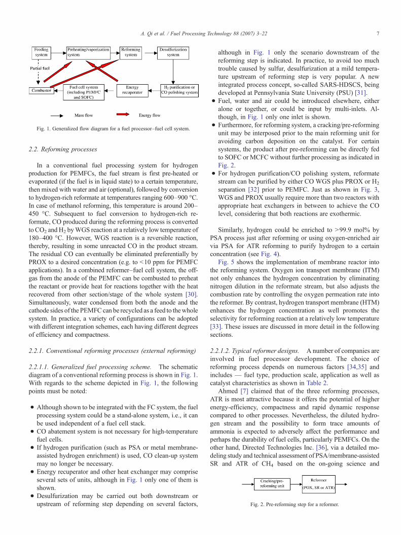
Fig. 1. Generalized flow diagram for a fuel processor–fuel cell system.
Fig. 2. Pre-reforming step for a reformer.
7A. Qi et al. / Fuel Processing Technology 88 (2007) 3–22
2.2. Reforming processes
In a conventional fuel processing system for hydrogenproduction for PEMFCs, the fuel stream is first pre-heated orevaporated (if the fuel is in liquid state) to a certain temperature,then mixed with water and air (optional), followed by conversionto hydrogen-rich reformate at temperatures ranging 600–900 °C.In case of methanol reforming, this temperature is around 200–450 °C. Subsequent to fuel conversion to hydrogen-rich re-formate, CO produced during the reforming process is convertedto CO2 and H2 byWGS reaction at a relatively low temperature of180–400 °C. However, WGS reaction is a reversible reaction,thereby, resulting in some unreacted CO in the product stream.The residual CO can eventually be eliminated preferentially byPROX to a desired concentration (e.g. to b10 ppm for PEMFCapplications). In a combined reformer–fuel cell system, the off-gas from the anode of the PEMFC can be combusted to preheatthe reactant or provide heat for reactions together with the heatrecovered from other section/stage of the whole system [30].Simultaneously, water condensed from both the anode and thecathode sides of the PEMFC can be recycled as a feed to thewholesystem. In practice, a variety of configurations can be adoptedwith different integration schemes, each having different degreesof efficiency and compactness.
2.2.1. Conventional reforming processes (external reforming)
2.2.1.1. Generalized fuel processing scheme. The schematicdiagram of a conventional reforming process is shown in Fig. 1.With regards to the scheme depicted in Fig. 1, the followingpoints must be noted:
• Although shown to be integrated with the FC system, the fuelprocessing system could be a stand-alone system, i.e., it canbe used independent of a fuel cell stack.
• CO abatement system is not necessary for high-temperaturefuel cells.
• If hydrogen purification (such as PSA or metal membrane-assisted hydrogen enrichment) is used, CO clean-up systemmay no longer be necessary.
• Energy recuperator and other heat exchanger may compriseseveral sets of units, although in Fig. 1 only one of them isshown.
• Desulfurization may be carried out both downstream orupstream of reforming step depending on several factors,
although in Fig. 1 only the scenario downstream of thereforming step is indicated. In practice, to avoid too muchtrouble caused by sulfur, desulfurization at a mild tempera-ture upstream of reforming step is very popular. A newintegrated process concept, so-called SARS-HDSCS, beingdeveloped at Pennsylvania State University (PSU) [31].
• Fuel, water and air could be introduced elsewhere, eitheralone or together, or could be input by multi-inlets. Al-though, in Fig. 1 only one inlet is shown.
• Furthermore, for reforming system, a cracking/pre-reformingunit may be interposed prior to the main reforming unit foravoiding carbon deposition on the catalyst. For certainsystems, the product after pre-reforming can be directly fedto SOFC or MCFC without further processing as indicated inFig. 2.
• For hydrogen purification/CO polishing system, reformatestream can be purified by either CO WGS plus PROX or H2
separation [32] prior to PEMFC. Just as shown in Fig. 3,WGS and PROX usually require more than two reactors withappropriate heat exchangers in between to achieve the COlevel, considering that both reactions are exothermic.
Similarly, hydrogen could be enriched to N99.9 mol% byPSA process just after reforming or using oxygen-enriched airvia PSA for ATR reforming to purify hydrogen to a certainconcentration (see Fig. 4).
Fig. 5 shows the implementation of membrane reactor intothe reforming system. Oxygen ion transport membrane (ITM)not only enhances the hydrogen concentration by eliminatingnitrogen dilution in the reformate stream, but also adjusts thecombustion rate by controlling the oxygen permeation rate intothe reformer. By contrast, hydrogen transport membrane (HTM)enhances the hydrogen concentration as well promotes theselectivity for reforming reaction at a relatively low temperature[33]. These issues are discussed in more detail in the followingsections.
2.2.1.2. Typical reformer designs. A number of companies areinvolved in fuel processor development. The choice ofreforming process depends on numerous factors [34,35] andincludes — fuel type, production scale, application as well ascatalyst characteristics as shown in Table 2.
Ahmed [7] claimed that of the three reforming processes,ATR is most attractive because it offers the potential of higherenergy-efficiency, compactness and rapid dynamic responsecompared to other processes. Nevertheless, the diluted hydro-gen stream and the possibility to form trace amounts ofammonia is expected to adversely affect the performance andperhaps the durability of fuel cells, particularly PEMFCs. On theother hand, Directed Technologies Inc. [36], via a detailed mo-deling study and technical assessment of PSA/membrane-assistedSR and ATR of CH4 based on the on-going science and
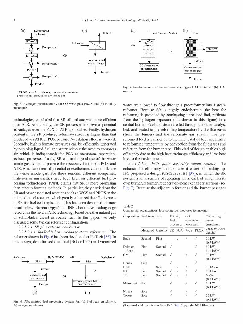
Fig. 3. Hydrogen purification by (a) CO WGS plus PROX and (b) Pd alloymembrane.
Fig. 5. Membrane-assisted fuel reformer: (a) oxygen ITM reactor and (b) HTMreactor.
Table 2Commercial organizations developing fuel processor technology
Corporation Fuel type focus Primaryfuelprocessor
COconversionprocesses
Technologystatus(maximumcapacity powerdensity)
Methanol Gasoline SR POX WGS PROX
Epyx Second First √ √ √ 50 kW(0.7 kW/h)
8 A. Qi et al. / Fuel Processing Technology 88 (2007) 3–22
technologies, concluded that SR of methane was more efficientthan ATR. Additionally, the SR process offers several potentialadvantages over the POX or ATR approaches. Firstly, hydrogencontent in the SR produced reformate stream is higher than thatproduced via ATR or POX because N2 dilution effect is avoided.Secondly, high reformate pressures can be efficiently generatedby pumping liquid fuel and water without the need to compressair, which is indispensable for PSA or membrane separation-assisted processes. Lastly, SR can make good use of the wasteanode gas as fuel to provide the necessary heat input. POX andATR, which are thermally neutral or exothermic, cannot fully usethe waste anode gas. For these reasons, different companies,institutes or universities have been keen on different fuel pro-cessing technologies. PNNL claims that SR is more promisingthan other reforming methods. In particular, they carried out theSR and other associated reactions such asWGS and PROX in themicro-channel reactors, which greatly enhanced the effectivenessof SR for fuel cell application. This has been described in moredetail below. Nuvera (Epyx) and INEL both have leading edgeresearch in the field ofATR technology based on either natural gasor sulfur-laden diesel as source fuel. In this paper, we onlydiscussed some typical reformer configurations.
2.2.1.2.1. SR plus external combustor2.2.1.2.1.1. IdaTech's heat exchange steam reformer. The
reformer shown in Fig. 6 has been developed at IdaTech [32]. Inthis design, desulfurized dual fuel (NG or LPG) and vaporized
Fig. 4. PSA-assisted fuel processing system for: (a) hydrogen enrichment,(b) oxygen enrichment.
water are allowed to flow through a pre-reformer into a steamreformer. Because SR is highly endothermic, the heat forreforming is provided by combusting unreacted fuel, raffinatefrom the hydrogen separator (not shown in this figure) in acentral burner. Fuel and steam are fed through the outer catalystbed, and heated to pre-reforming temperature by the flue gases(from the burner) and the reformate gas stream. The pre-reformed feed is transferred to the inner catalyst bed, and heatedto reforming temperature by convection from the flue gases andradiation from the burner tube. This kind of design enables highefficiency due to the high heat exchange efficiency and less heatloss to the environment.
2.2.1.2.1.2. IFC's plate assembly steam reactor. Toenhance the efficiency and to make it easier for scaling up,IFC proposed a design (US6203587B1 [37]), in which the SRsystem is an assembly of repeating units, each of which has itsown burner, reformer, regenerator–heat exchanger sections (seeFig. 7). Because the adjacent reformer and the burner passages
DaimlerBenz
First Second √ √ 50 kW(1.1 kW/h)
GM First Second √ √ √ 30 kW(0.5 kW/h)
Honda Sole √ √HBT Sole √ √ 7–42 kWIFC First Second √ √ √ √ 100 kWJM First Second √ √ √ 6 kW
(0.5 kW/h)Mitsubishi Sole √ √ √ 10 kW
(0.4 kW/h)Nissan Sole √ √ √Toyota Sole √ √ √ 25 kW
(0.6 kW/h)
(Reprinted with permission from Ref. [34]. Copyright 2001 Elsevier).
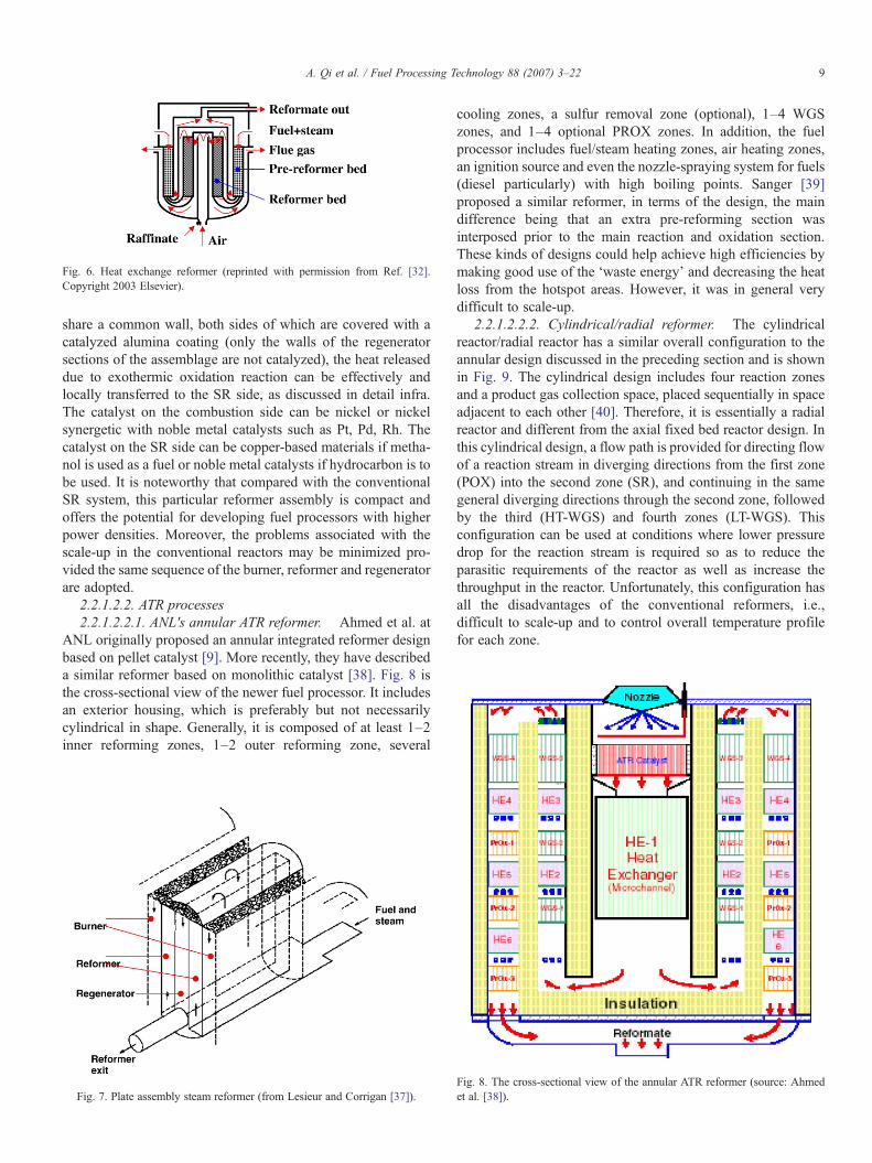
Fig. 6. Heat exchange reformer (reprinted with permission from Ref. [32].Copyright 2003 Elsevier).
9A. Qi et al. / Fuel Processing Technology 88 (2007) 3–22
share a common wall, both sides of which are covered with acatalyzed alumina coating (only the walls of the regeneratorsections of the assemblage are not catalyzed), the heat releaseddue to exothermic oxidation reaction can be effectively andlocally transferred to the SR side, as discussed in detail infra.The catalyst on the combustion side can be nickel or nickelsynergetic with noble metal catalysts such as Pt, Pd, Rh. Thecatalyst on the SR side can be copper-based materials if metha-nol is used as a fuel or noble metal catalysts if hydrocarbon is tobe used. It is noteworthy that compared with the conventionalSR system, this particular reformer assembly is compact andoffers the potential for developing fuel processors with higherpower densities. Moreover, the problems associated with thescale-up in the conventional reactors may be minimized pro-vided the same sequence of the burner, reformer and regeneratorare adopted.
2.2.1.2.2. ATR processes2.2.1.2.2.1. ANL's annular ATR reformer. Ahmed et al. at
ANL originally proposed an annular integrated reformer designbased on pellet catalyst [9]. More recently, they have describeda similar reformer based on monolithic catalyst [38]. Fig. 8 isthe cross-sectional view of the newer fuel processor. It includesan exterior housing, which is preferably but not necessarilycylindrical in shape. Generally, it is composed of at least 1–2inner reforming zones, 1–2 outer reforming zone, several
Fig. 7. Plate assembly steam reformer (from Lesieur and Corrigan [37]).
cooling zones, a sulfur removal zone (optional), 1–4 WGSzones, and 1–4 optional PROX zones. In addition, the fuelprocessor includes fuel/steam heating zones, air heating zones,an ignition source and even the nozzle-spraying system for fuels(diesel particularly) with high boiling points. Sanger [39]proposed a similar reformer, in terms of the design, the maindifference being that an extra pre-reforming section wasinterposed prior to the main reaction and oxidation section.These kinds of designs could help achieve high efficiencies bymaking good use of the ‘waste energy’ and decreasing the heatloss from the hotspot areas. However, it was in general verydifficult to scale-up.
2.2.1.2.2.2. Cylindrical/radial reformer. The cylindricalreactor/radial reactor has a similar overall configuration to theannular design discussed in the preceding section and is shownin Fig. 9. The cylindrical design includes four reaction zonesand a product gas collection space, placed sequentially in spaceadjacent to each other [40]. Therefore, it is essentially a radialreactor and different from the axial fixed bed reactor design. Inthis cylindrical design, a flow path is provided for directing flowof a reaction stream in diverging directions from the first zone(POX) into the second zone (SR), and continuing in the samegeneral diverging directions through the second zone, followedby the third (HT-WGS) and fourth zones (LT-WGS). Thisconfiguration can be used at conditions where lower pressuredrop for the reaction stream is required so as to reduce theparasitic requirements of the reactor as well as increase thethroughput in the reactor. Unfortunately, this configuration hasall the disadvantages of the conventional reformers, i.e.,difficult to scale-up and to control overall temperature profilefor each zone.
Fig. 8. The cross-sectional view of the annular ATR reformer (source: Ahmedet al. [38]).
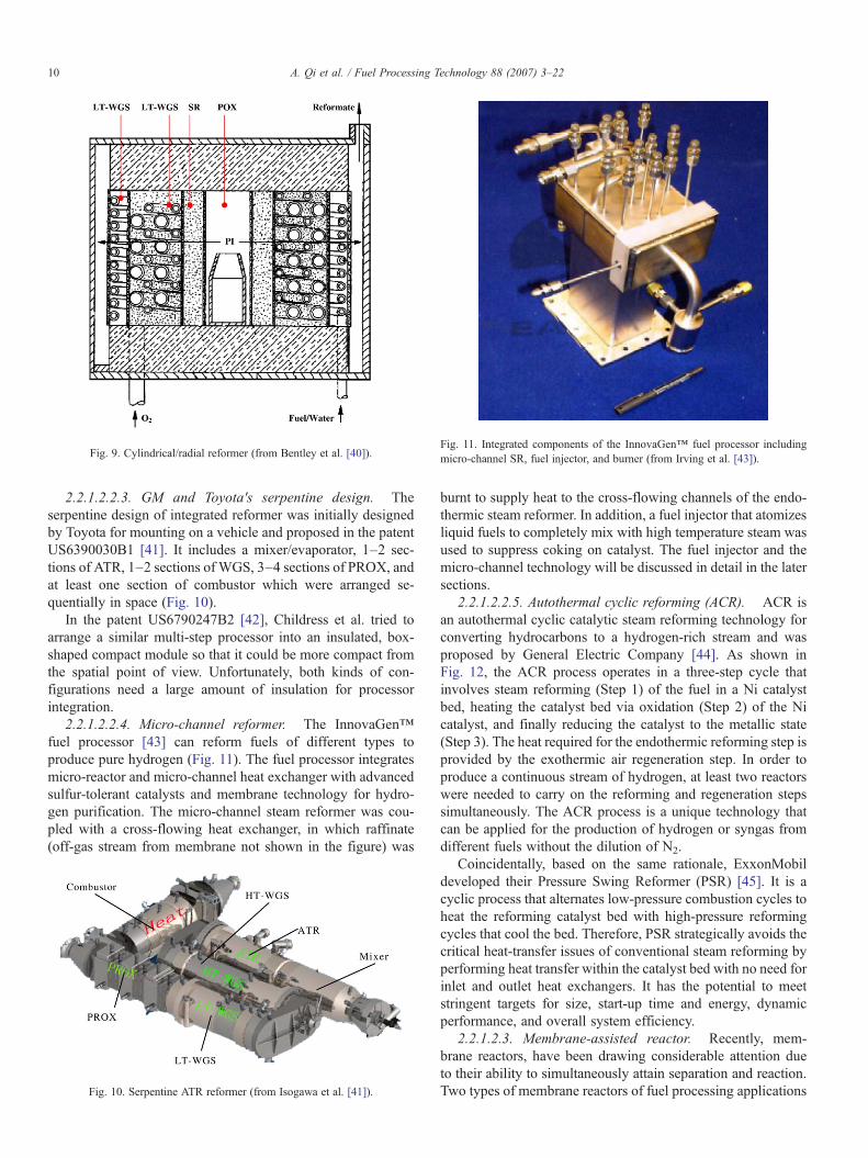
Fig. 11. Integrated components of the InnovaGen™ fuel processor includingmicro-channel SR, fuel injector, and burner (from Irving et al. [43]).Fig. 9. Cylindrical/radial reformer (from Bentley et al. [40]).
10 A. Qi et al. / Fuel Processing Technology 88 (2007) 3–22
2.2.1.2.2.3. GM and Toyota's serpentine design. Theserpentine design of integrated reformer was initially designedby Toyota for mounting on a vehicle and proposed in the patentUS6390030B1 [41]. It includes a mixer/evaporator, 1–2 sec-tions of ATR, 1–2 sections of WGS, 3–4 sections of PROX, andat least one section of combustor which were arranged se-quentially in space (Fig. 10).
In the patent US6790247B2 [42], Childress et al. tried toarrange a similar multi-step processor into an insulated, box-shaped compact module so that it could be more compact fromthe spatial point of view. Unfortunately, both kinds of con-figurations need a large amount of insulation for processorintegration.
2.2.1.2.2.4. Micro-channel reformer. The InnovaGen™fuel processor [43] can reform fuels of different types toproduce pure hydrogen (Fig. 11). The fuel processor integratesmicro-reactor and micro-channel heat exchanger with advancedsulfur-tolerant catalysts and membrane technology for hydro-gen purification. The micro-channel steam reformer was cou-pled with a cross-flowing heat exchanger, in which raffinate(off-gas stream from membrane not shown in the figure) was
Fig. 10. Serpentine ATR reformer (from Isogawa et al. [41]).
burnt to supply heat to the cross-flowing channels of the endo-thermic steam reformer. In addition, a fuel injector that atomizesliquid fuels to completely mix with high temperature steam wasused to suppress coking on catalyst. The fuel injector and themicro-channel technology will be discussed in detail in the latersections.
2.2.1.2.2.5. Autothermal cyclic reforming (ACR). ACR isan autothermal cyclic catalytic steam reforming technology forconverting hydrocarbons to a hydrogen-rich stream and wasproposed by General Electric Company [44]. As shown inFig. 12, the ACR process operates in a three-step cycle thatinvolves steam reforming (Step 1) of the fuel in a Ni catalystbed, heating the catalyst bed via oxidation (Step 2) of the Nicatalyst, and finally reducing the catalyst to the metallic state(Step 3). The heat required for the endothermic reforming step isprovided by the exothermic air regeneration step. In order toproduce a continuous stream of hydrogen, at least two reactorswere needed to carry on the reforming and regeneration stepssimultaneously. The ACR process is a unique technology thatcan be applied for the production of hydrogen or syngas fromdifferent fuels without the dilution of N2.
Coincidentally, based on the same rationale, ExxonMobildeveloped their Pressure Swing Reformer (PSR) [45]. It is acyclic process that alternates low-pressure combustion cycles toheat the reforming catalyst bed with high-pressure reformingcycles that cool the bed. Therefore, PSR strategically avoids thecritical heat-transfer issues of conventional steam reforming byperforming heat transfer within the catalyst bed with no need forinlet and outlet heat exchangers. It has the potential to meetstringent targets for size, start-up time and energy, dynamicperformance, and overall system efficiency.
2.2.1.2.3. Membrane-assisted reactor. Recently, mem-brane reactors, have been drawing considerable attention dueto their ability to simultaneously attain separation and reaction.Two types of membrane reactors of fuel processing applications

Fig. 12. Schematic diagram for the ACR technology (from Kumar et al. [44]).
11A. Qi et al. / Fuel Processing Technology 88 (2007) 3–22
are being researched: the oxygen ITM reformer and the HTMreformer. The controlled supply of pure oxygen in the oxygenITM reformer has many advantages over conventional POXreactors, including avoiding fuel and O2 premixing before theoccurrence of reaction, eliminating NOx emissions, eliminatingthe use of costly cryogenic oxygen or of nitrogen removal fromthe product streams, and above all the fine controlling of hotspottemperature so as to low the requirement for refractory materialfor both catalysts and the reformers [46]. By contrast, the HTMreformer has other advantages besides compactness, includingenhancing the reaction extent favorable for hydrogen produc-tion, enabling high concentration of hydrogen and so on [47].The coupling of oxygen transport membrane (OTM) with thepalladium-based hydrogen-permeable membrane (HPM) pro-posed by Praxair, Inc. [48] offered a brand-new perspective onhow to produce hydrogen (Fig. 13). It was so compact andefficient that it not only combined the advantages of the ITM andHTM but also the merits of ATR and SR at the same time,producing high concentration of hydrogen without compromis-ing the advantage of the ATR, and ‘hotspot’ temperature couldbe effectively controlled by the transportation of oxygen throughthe ceramic membrane. However, in ATR or POX reformerassociated with membranes, heavy duty air compressors areneeded. Consider, for instance, PEMFC systems wherein theoperation pressure is generally no less than 2 atm. In order toproduce a hydrogen stream above 2 atm, an operation pressure of
Fig. 13. The coupling of OTM with HPM for pure hydrogen generation (fromSchwartz et al. [48]).
more than 5 atm for the fuel processor is required assuminghydrogen composition in the reformate is 40 mol%. This is truebecause the separation is driven by the partial pressure differ-ential across the membrane. As such, to produce pure hydrogenstream at 2 atm, the total pressure on the reformate side has to besignificantly higher to ensure that the hydrogen partial pressureis considerably higher than hydrogen pressure on the permeateside. In practice, a pressure above 10 atm is adopted due to thehigh pressure drop through the whole system.
2.2.1.2.4. PSA-assisted reforming process. PressureSwing Adsorption (PSA) could be used to separate or purifydifferent permanent gases with different absorbents at differentoperation conditions. The technologies for O2 separation fromair based on carbon molecular sieve and hydrogen purificationfrom reformate based on zeolite are quite mature. Unlike mem-brane separation, PSA generally could only be used eitherupstream (for oxygen enrichment) or downstream (for hydrogen
Fig. 14. Integrated hydrogen generation system including PSA system (fromAaron et al., 2004 [50]).

12 A. Qi et al. / Fuel Processing Technology 88 (2007) 3–22
enrichment) of the reformer. Therefore, its integration with thereformer is relatively limited. Oxygen enrichment by PSA couldbe introduced into ATR as well as FC, both of which could helpenhance FC output. Researchers at the Royal Military College(RMC) have tested this technology with their ATR [49]. UsingPSA for purifying hydrogen is quite popular and is a relativelymature technology. Tim Aaron [50] at Praxair Inc. designed thePSA-assisted reforming system, in which the hydrogen withhigh concentration via PSAwas fed to PEMFC, while the raffi-nate was combusted for providing the heat for the steam refor-ming. The whole system can be made so compact that it can beinstalled on a single platform (Fig. 14). Nevertheless, like metalmembrane separation, PSA also needs high operation pressure,and was only competitive for high-throughput apparatus. Theeffectiveness of the process depends on the differential pressure.
It should be pointed out that hydrogen enrichment could alsobe carried out by withdrawing components other than hydrogenin the reformate stream. So far, using CaO or similar absorbentto chemically absorb CO2 from the reformate stream appears tobe most popular [51]. To some extent, this could be consideredas another direction of integrated fuel processor although thistopic is beyond the scope of this review.
2.2.2. Internal reforming (integration of reformer with the FC)Internal reforming achieves fuel reforming in a unit that is
essentially an integral part of a fuel cell rather than in separate
Fig. 16. Fuel, air and water distribution in a combined fuel processor–FCsystem.Fig. 15. Fuel, air and water distribution in a stand-alone fuel processor.
reactor. Internal reforming is attractive from the perspective ofincreased system compactness and efficiency, faster loadingresponse and significant cost reduction [52]. Moreover, theendothermic internal reforming will act as an efficient coolingsystem to the fuel cell chamber. However, this kind of designgenerally could only be used for providing fuel for SOFC orMCFC taking into consideration that large amount of CO oreven unconverted hydrocarbon still exists in the reformatestream. Typically, considering that only a fuel utilization of 77%could be achieved, there is a loose of 23% efficiencies from thestart.
Depending upon the intimacy of contact between thereformer and the FC, internal reforming can be further classified
Fig. 17. Heat recovery by separated water flows.
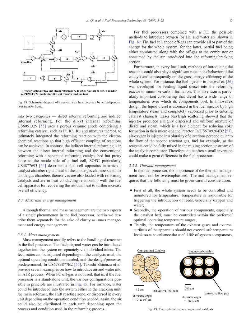
Fig. 19. Conventional versus engineered catalysts.
Fig. 18. Schematic diagram of a system with heat recovery by an independentheat transfer liquid.
13A. Qi et al. / Fuel Processing Technology 88 (2007) 3–22
into two categories — direct internal reforming and indirectinternal reforming. For the direct internal reforming,US6051329 [53] uses a porous ceramic anode comprising areforming catalyst, such as Pt, Rh, Ru and mixtures thereof, tointimately integrated the reforming reaction with the electro-chemical reactions so that high efficient coupling of reactionscan be achieved. In contrast, the indirect internal reforming is inbetween the direct internal reforming and the conventionalreforming with a separated reforming catalyst bed but prettyclose to the anode side of a fuel cell, SOFC particularly.US4877693 [54] described a fuel cell apparatus in which acatalyst chamber right ahead of the anode gas chambers and theanode gas chambers themselves are also loaded with reformingcatalysts and are in heat conducting relationship with the fuelcell apparatus for recovering the residual heat to further increaseoverall efficiency.
2.3. Mass and energy management
Although thermal and mass management are the two aspectsof a single phenomenon in the fuel processor, herein we des-cribe them separately for the sake of clarity as: mass manage-ment and energy management.
2.3.1. Mass managementMass management usually refers to the handling of reactants
in the fuel processor. The fuel, air, and water can be introducedtogether into the system or separately via individual inlets. Thefeed ratios can be adjusted depending on the catalysts used, theoptimal operating conditions needed, and the design/processespredetermined. In US6783877B2 [55], Takashi Shimazu et al.provide several examples on how to introduce air and water intoan ATR process. When FC off-gas is not used, that is, if the fuelprocessor is a stand-alone unit, the various configurations pos-sible in principle are illustrated in Fig. 15. For instance, watercould be introduced into the system either in the cracking unit,the main reformer, the shift reacting zone, or dispersed in everyunit depending on the operation condition needed; again, the aircould also be distributed in each unit depending upon theprocess and condition used in the reforming process.
For fuel processors combined with a FC, the possiblemethods to introduce oxygen (or air) and water are shown inFig. 16. The fuel cell anode off-gas can provide all or part of theenergy for the whole system, for the latter, partial fuel beingeither combusted along with the off-gas at the combustor orconsumed by the air introduced into the reforming/crackingsection.
Furthermore, in every local unit, methods of introducing thereactants could also play a significant role on the behavior of thecatalyst and consequently on the gross energy efficiency of thewhole system. For instance, the fuel injector in InnovaTek [56]was developed for feeding liquid diesel into the reformingreactor to minimize carbon formation. This invention is partic-ularly important considering that diesel has a wide range oftemperatures over which its components boil. In InnovaTekdesign, the liquid diesel is atomized in the fuel injector by hightemperature steam and completely vaporized prior to enteringcatalyst channels. Laser Rayleigh scattering showed that theinjector produced a highly dispersed and uniform mixture ofdiesel and steam, which is a key element for reducing cokeformation in their micro-channel reactor. In US6709264B2 [57],air/oxygen is injected in a plurality of directions perpendicular tothe flow of the second reactant gas, fuel for example, so thereagents could be fully mixed in the mixing section upstream ofthe catalytic combustor. Therefore, quite often a small inventioncould make a great difference in the fuel processor.
2.3.2. Thermal managementIn the fuel processor, the importance of the thermal manage-
ment need not be overemphasized. Thermal management re-quires that the following must be given careful consideration:
• First of all, the whole system needs to be controlled andmonitored for temperature. Temperature is responsible fortriggering the introduction of feeds, especially oxygen andwater;
• Secondly, the operation of various components, especiallythe catalyst bed, must be controlled within the preferred/optimal operating temperature ranges;
• Thirdly, the temperature of the exhaust gases and externalsurfaces of the apparatus should not exceed safe temperaturelevels so as to enhance the useful life of system components;
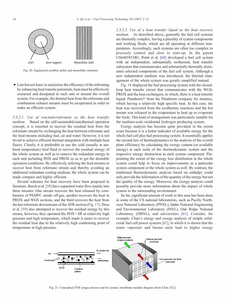
Fig. 20. Engineered scrubber pellet and monolithic substrate.
14 A. Qi et al. / Fuel Processing Technology 88 (2007) 3–22
• Last but not least, to maximize the efficiency of the reformingby enhancing heat transfer potentials, heat must be effectivelyextracted and dissipated in each unit or around the overallsystem. For example, the thermal heat from the reformate andcombustion exhaust streams must be recuperated in order tomake an efficient system.
2.3.2.1. Use of reactants/reformate as the heat transfermedium. Based on the self-sustainable/autothermal operationconcept, it is essential to recover the residual heat from thereformate stream by exchanging the heat between reformate andthe feed streams including fuel, air and water. However, it is nottrivial to achieve efficient thermal integration with multiple heatfluxes. Clearly, it is preferable to use the cold (usually at am-bient temperature) feed fluid to recover the residual energy ofthe whole system as well as to remove the redundant energy ineach unit including POX and PROX so as to get the desirableoperation conditions. By effectively utilizing the feed streams torecover heat from reformate stream and thereby avoiding anadditional redundant cooling medium, the whole system can bemade compact and highly efficient.
Several schemes for heat recovery have been proposed inliterature. Burch et al. [58] have separated water flowmainly intothree streams: One stream recovers the heat released by com-bustion of PEMFC anode off-gas, another recovers the heat inPROX and WGS sections, and the third recovers the heat fromthe hot reformate downstream of the ATR section (Fig. 17). Dosset al. [59] also attempted to recover the residual energy by thismeans, however, they operated the POX+SR at relatively highpressure and high temperature, which made it easier to recoverthe residual heat due to the relatively high condensing point oftemperature at high pressure.
Fig. 21. Conceptual ITM syngas process and its ceram
2.3.2.2. Use of a heat transfer liquid as the heat recoverymedium. As described above, generally the fuel cell systemsare thermally complex, having a plurality of system componentsand working fluids, which are all operating at different tem-peratures. Accordingly, such systems are often too complex toprecisely control and slow to start-up. In the patentUS6485853B1, Pettit et al. [60] developed a fuel cell systemwith an independent, substantially isothermal, heat transfersubsystem that communicates and substantially thermally domi-nates selected components of the fuel cell system. Although anew independent medium was introduced, the thermal man-agement of the whole system was greatly simplified instead.
Fig. 18 displayed the fuel processing system with the closed-loop heat transfer circuit that communicates with the WGS,PROX and the heat exchangers, in which, there is a heat transferliquid, Paratherm® from the Paratherm company for instance,which having a relatively high specific heat. In this case, theheat was recovered from the exothermic reactions and the hotstream was released in the evaporators to heat up or evaporatethe feeds. This kind of arrangement was particularly suitable forthe medium-scale residential hydrogen producing system.
Exergy analysis has become quite prevalent in the recentyears because it is a better indicator of available energy for thewhole fuel cell plus fuel processing system. It essentially appliesthe second law of thermodynamics to the analysis of the overallplant efficiency by calculating the exergy content (or availableenergy) at each node of the thermodynamic system and therespective energy destruction in each system component. Pin-pointing the extent of the exergy loss distribution in the wholesystem could help to focus on improvements in a particularsystem component or the whole system as well. By contrast, thetraditional thermodynamic analysis based on enthalpy couldonly provide the information of the quantity of the energy but notthe quality of the energy. Moreover, the exergy analysis couldpossibly provide more information about the impact of wholesystem to the surrounding environment.
So far, significant amount of work in this area has been donein some of the US national laboratories, such as Pacific North-west National Laboratory (PNNL), Idaho National Engineeringand Environmental Laboratory (INEL), Oak Ridge NationalLaboratory (ORNL), and universities [61]. Consider, forexample, Chan's energy and exergy analysis of simple solid-oxide fuel cell power systems [62], in which it is shown that thewater vaporizer and burner units lead to higher exergy
ic membrane module diagram (from Chen [82]).
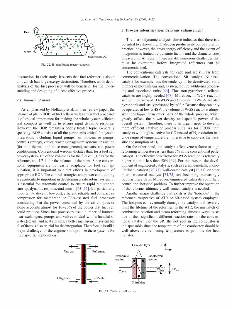
Fig. 22. H2 membrane reactor concept.
15A. Qi et al. / Fuel Processing Technology 88 (2007) 3–22
destruction. In their study, it seems that fuel reformer is also aunit which had large exergy destruction. Therefore, an in-depthanalysis of the fuel processor will be beneficial for the under-standing and designing of a cost-effective process.
2.4. Balance of plant
As emphasized by Holladay et al. in their review paper, thebalance of plant (BOP) of fuel cells as well as their fuel processoris of crucial importance for making the whole system efficientand compact as well as to ensure rapid dynamic response.However, the BOP remains a poorly treated topic. Generallyspeaking, BOP consists of all the peripherals critical for systemintegration, including liquid pumps, air blowers or pumps,controls strategy, valves, water management systems, insulation(for both thermal and noise management), sensors, and powerconditioning. Conventional wisdom dictates that, for a fuel cellpower system, 1/3 of the volume is for the fuel cell, 1/3 is for thereformer, and 1/3 is for the balance of the plant. Since conven-tional equipment are not easily adaptable for fuel cell ap-plication, it is important to direct efforts in development ofappropriate BOP. The control strategies and power conditioningare particularly important in developing a safe robust system. Itis essential for automatic control to ensure rapid but smoothstart-up, dynamic response and control [63–65]. It is particularlyimportant to develop low cost, efficient, reliable and compact aircompressor for membrane or PSA-assisted fuel processorconsidering that the power consumed by the air compressoralone accounts almost for 10–20% of the power that fuel cellcould produce. Since fuel processors use a number of burners,heat exchangers, pumps and valves to deal with a handful ofwater (steam) and heat streams, a better management system forall of them is also crucial for the integration. Therefore, it is still amajor challenge for the engineers to optimize these systems fortheir specific applications.
Fig. 23. Catalytic
3. Process intensification: dynamic enhancement
The thermodynamic analysis above indicates that there is apotential to achieve high hydrogen productivity out of a fuel. Inpractice, however, the gross energy efficiency and the extent ofintegration is limited by dynamic factors and the characteristicsof each unit. At present, there are still numerous challenges thatmust be overcome before integrated reformers can becommercialized.
The conventional catalysts for each unit are still far fromcommercialization. The conventional SR catalyst, Ni-basedcatalyst for example, has the tendency to be deactivated via anumber of mechanisms and, as such, require additional process-ing and associated units [66]. Thus non-pyrophoric, reliablecatalysts are highly needed [67]. Moreover, in WGS reactionsection, Fe/Cr-based HT-WGS and Cu-based LT-WGS are alsopyrophoric and easily poisoned by sulfur. Because they can onlybe operated at low GHSV, the volume of WGS reactor is almostsix times bigger than other parts of the whole process, whichgreatly offsets the power density and specific power of theoverall system. Therefore, there is an urgent need to developmore efficient catalyst or process [68]. As for PROX unit,catalysts with high selective for CO instead of H2 oxidation in awide range of temperature are imperative to suppress the para-sitic consumption of H2.
On the other hand, the catalyst effectiveness factor at highreforming temperature is less than 5% in the conventional pelletcatalyst. The effectiveness factor for WGS reaction is relativelyhigher but still less than 50% [69]. For this reason, the devel-opment of engineered catalysts, such as ceramic/metallic mono-lith/foam catalyst [70,71], wall-coated catalyst [72,73], or othermicro-structured catalyst [74,75] are becoming increasinglypopular these days. Moreover, engineered catalysts could helpcontrol the ‘hotspot’ problem. To further improve the operationof the reformer ultimately wall-coated catalyst is needed.
Another major challenge that exists is the ‘hotspots’ in thereformer irrespective of ATR or SR-based system employed.The hotspots can eventually damage the catalyst and severelylimit the lifetime of the reformer. In the ATR, the mismatch ofcombustion reaction and steam reforming almost always existsdue to their significant different reaction rates on the conven-tional catalyst. For the SR, the hot spot in the combustor isindispensable since the temperature of the combustor should bewell above the reforming temperature to promote the heattransfer.
wall reactor.

Fig. 24. Wavyplate heat exchanger/vaporizer (from Isogawa et al. [41]).
16 A. Qi et al. / Fuel Processing Technology 88 (2007) 3–22
Another major challenge is the thermal integration of theoverall system. The thermal energy needed for the reactionsmust not only be supplied in a smooth and rapid manner fromthe energy available in the individual units but also at a desiredlevel of temperature.
To date, significant amount of work has been carried out inthe process intensification to enhance the mass and heat transferas well as to accurately control the reaction rates. This processintensification concept is significant embodied in every unit/stage in the fuel processor. In this review we arbitrarily classi-fied them into the following categories: (i) reaction rate en-hancement by engineered catalyst, (ii) reaction rate control andequilibrium promotion by membranes assistance, and (iii) accu-rate reaction rate control and heat withdrawing/provision bymicro-technologies.
3.1. Engineered catalyst and desulfurizer
Highly efficient catalysts are the essential requirement foran efficient and compact fuel processor system. Hence,fundamental research on the development of new and effectivecatalysts is being carried out by numerous research groups. Forreforming reaction, ANL developed noble metal-based catalystas well as perovskite catalysts in both pellet form andmonolithic/foam substrates [76]; for WGS, medium temperature
Fig. 25. PNNL's micro-channel gasoline vaporizer for 50 kW fuel processing syste
catalyst rather that HT plus LT-WGS catalysts is beingdeveloped by Nextech Materials, USA. For instance, Ruettinger[77] used oxides of tin, gallium and combinations thereof tomodify the precious metal catalyst on inorganic oxide support soas to suppress the formation of methane. For PROX catalyst, inorder to achieve high selectivity at a wide window of operationtemperatures, noble metals' support on different supports wasinvestigated by introducing different promoters. Meanwhile,engineered catalysts such as metal foam supported Pt catalyst forselective oxidation of CO in hydrogen-rich stream [70,71],plate-type copper-based catalysts for LT-WGS [73] are enthu-siastically carried out.
Of all the research activities, the most interesting develop-ment is of catalyst engineering [78]. If the catalyst is supportedon the cordierite/metallic monolith, called engineered catalystgenerally, it has a diffusion length for the reactants one to twoorders of magnitude lower than the conventional catalyst (seeFig. 19) [79]. For this reason, all the catalyst can fully contributetheir activity at intrinsic reaction rates, which is very crucial forthe quick reactions at high temperature. Under this condition, themass/heat transfer can be enhanced, as such the reaction timescale can be decreased from the original 1–10 s to 1–100 ms.Take the WGS reaction for example, the original reaction timescale is around 1 s, while the time scale could be decreased to25 ms as per the new findings by PNNL [80,81]. It should benoted that new reactor configurations have to be applied in linewith the progress of engineered catalysts.
For sulfur scrubber in the fuel processor, most commonly,ZnO pellets are used as the absorbent in the sulfur scrubberdownstream the reformer. According to the shrinking-coremodel, the pellet usage accounts for only less than 50% of thetotal absorbent due to the inhibition of produced ZnS to thetransfer of H2S into the core of the pellet. For this reason,engineered pellet with surface-deposited ZnO or monolithicsubstrate supported ZnO has to be developed (Fig. 20).
3.2. Membrane-assisted reforming
3.2.1. Oxygen ion transport membranes (ITMs)It is well known that ATR offers the possibility to directly
couple the exothermic combustion reaction and the endothermic
m and its flow diagram of laminated micro-channel (from Matson et al. [108]).

Fig. 26. Differential temperature water–gas shift reactor (from TeGrotenhuis et al. [83]).
17A. Qi et al. / Fuel Processing Technology 88 (2007) 3–22
reaction on the same catalyst bed makes the whole system veryefficient and to some extent help minimize the hotspots. How-ever, because the combustion reaction rate is at least one order ofmagnitude faster than that of the steam reforming on the generalcatalyst, the heat produced by the combustion can not beremoved by the steam reforming over the same time or lengthscale, and, as such, the ultimate goal of ATR can not be com-pletely attained.
Oxygen ITMs-assisted ATR reforming [82,44] is a revo-lutionary platform technology for producing hydrogen andsyngas for applications in power generation. The ITM Syngasprocess provides a lower-cost method for converting naturalgas to hydrogen and syngas by combining air separation andnatural gas partial oxidation or ATR in a single-step ceramic
Fig. 27. Multi-stage PROX reactor (a) and micro-channe
membrane reactor, with the potential for capital cost savings ofover 30%.
An ITM ceramic membranes was fabricated byAir Productionand Chemical, Inc. from non-porous, multi-component, metallicoxides [e.g., (La1−xCax)yFeO3−δ, which is thermodynamicalystable in both reducing and oxidizing atmosphere with therequisite mechanical properties] and operate at high temperatureswith exceptionally high oxygen flux and selectivity. A concep-tualization of the ITMSyngas technology is shown in Fig. 21. TheITMmodulewas created vertically by stackingwafers, whichwasbuilt from pilot-scale membranes. The wafers were joined andsealed to ceramic spacers that create an open channel for the flowof NG and syngas between wafers. Oxygen ions from low-pressure air permeate the ceramic membrane and are consumed
l PROX reactor (b) (from TeGrotenhuis et al. [80]).
18 A. Qi et al. / Fuel Processing Technology 88 (2007) 3–22
through chemical reactions, creating a chemical driving force thatpulls oxygen ions across the membrane at high rates.
At present, the ITM syngas technology is being scaled upfrom a 24000 SCFD process development unit to a one millionSCFD subscale engineering prototype one.
3.2.2. H2-permeable membrane (HPM)-assisted reformingAs discussed above, HPM-assisted reforming is not only able
to generate high concentration hydrogen, but also to removehydrogen from the reaction system, which helps overcome thethermodynamic limitation imposed by the reversible nature ofthe reaction, especially at relatively high operating temperaturewhich is favorable for reaction kinetics [83–85].
Three different types of hydrogen permeable membranes aretechnically possible, each achieving hydrogen separation bydifferent mechanism. These are ion (proton) transport separationsystems, atomic transport/dense metallic separation systems,and molecular transport/micro-porous separation systems.
The most common one is the atomic transport/dense metallicseparation systems (Fig. 22), in which hydrogen permeates themembrane as a form of atom. Edlund et al. [86,87] providedmembrane modules including one or more hydrogen-selectivemembranes supported on a screen structure, for example, 35 wt.% Pd–45 wt.% copper support on fine mesh screens. Note itcould also be used as a hydrogen purifier independent of a fuelprocessor or fuel cell stack. However, this kind of membraneneeds suitable operation temperature or atmosphere to avoidhydrogen embrittlement or impurity damage. With the presenceof trace amount of H2S, the permeability of metal membranescould be significantly damaged. So far, much effort is taken toenhance the sulfur-tolerant of the metal membrane by introduc-ing various amounts of other metals into Pd to form Pd alloy,such as Pd–Ag, Pd–Cu [88,89]. However, the inhibition mech-anism of hydrogen permeability by H2S to metal membrane isstill not quite clear although it has been observed that the failureof membrane depended mainly on the concentration of sulfurrather than the exposure time [90].
Based on molecular transport/micro-porous H2 separationmechanism, Sandia National Laboratories [91] developed arobust, high-selective, defect-free thin film zeolite membrane(pore size ∼5.5 Å) supported on alumina or composite oxidestainless steel support. From room temperatures and up to500 °C and 16 psig, the extremely high H2 selectivity over CO2,
Fig. 28. Schematic diagram and photograph of a micro-scale fuel processor
CO, and CH4 of the membrane suggested these membraneswould be useful for industrial H2 separations and purification. Inaddition, with the presence of 200 ppm H2S, there was noindication of damage to the membrane, though only short-termstudies were explored. Similarly, Oyama and his colleagues inVirginia Polytechnic Institute and State University developedNanosil, a silica membrane with silica layer supported on porousVycor glass or alumina by chemical vapor deposition (CVD)method. It not only showed high H2 permeance, unprecedentedselectivity (100% with respect to CH4, CO and CO2) andexcellent stability at hydrothermal conditions [92–95]. Theyhave successfully utilized it in a membrane reactor for CH4 dryreforming [96].
Recently, Oak Ridge National Laboratory addressed pyro-chlore/perovskite proton transport membranes based on thesimilar hydrogen separation mechanism to proton exchangemembrane: the ion (proton) transport separation mechanism[97]. This approach broadened the operation temperaturewindow, 300–800 °C, and the sulfur resistance was also greatlyimproved. They were planning for the long-term stability testand trying to develop asymmetric membranes.
3.3. Micro-technologies
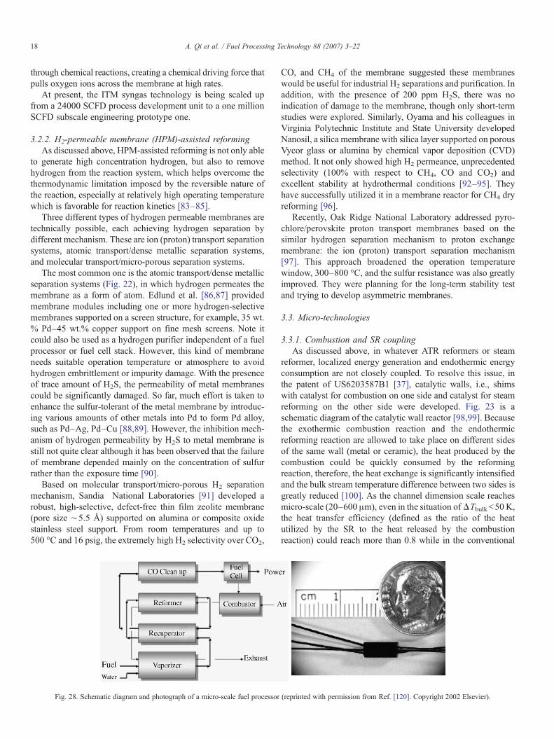
3.3.1. Combustion and SR couplingAs discussed above, in whatever ATR reformers or steam
reformer, localized energy generation and endothermic energyconsumption are not closely coupled. To resolve this issue, inthe patent of US6203587B1 [37], catalytic walls, i.e., shimswith catalyst for combustion on one side and catalyst for steamreforming on the other side were developed. Fig. 23 is aschematic diagram of the catalytic wall reactor [98,99]. Becausethe exothermic combustion reaction and the endothermicreforming reaction are allowed to take place on different sidesof the same wall (metal or ceramic), the heat produced by thecombustion could be quickly consumed by the reformingreaction, therefore, the heat exchange is significantly intensifiedand the bulk stream temperature difference between two sides isgreatly reduced [100]. As the channel dimension scale reachesmicro-scale (20–600 μm), even in the situation ofΔTbulkb50 K,the heat transfer efficiency (defined as the ratio of the heatutilized by the SR to the heat released by the combustionreaction) could reach more than 0.8 while in the conventional
(reprinted with permission from Ref. [120]. Copyright 2002 Elsevier).
19A. Qi et al. / Fuel Processing Technology 88 (2007) 3–22
heat exchanger it could be only as high as 0.6. Yee et al. basedon this technologies developed plate reactor for SR of gasolineas well as WGS and PROX reactions, and the efficiency of theintegrated fuel processor was calculated using Pro/II SimSci.The baseline system efficiency was calculated to be 79.5%.Several performance improvements were identified that couldachieve a system efficiency of 83.6% by modifying variousoperating parameters [101]. Furthermore, by adjusting the cata-lyst amount/activity at different place on both sides, the hotspotor cold-spot could be greatly suppressed or even averted.
3.3.2. Combustion/vaporization integrationIn a number of fuel processor inventions, the burner is
interlaced with the recuperator so as to make the coupling of heatstreammore efficient, and to abate the heat losses by overcomingthe spatial separation of the heat sink with a relatively smallweight. Therefore, the whole energy heat exchanger can beoperated in such a way that the heat generation can be betteradapted to the dynamic load variation conditions with relativelyshort lag times.
The design in Patent US6390030B1 [41] uses a heat ex-changer with wave-shaped plates (Fig. 24). Because the refor-ming raw material flow path units and the combustion flow pathones are alternately layered, and also because the contactingareas between two flow are greatly expanded by this kind ofwave-shaped plates, it is very efficient. A similar concept wasalso proposed by Brooks et al. [102] for their wavy plateassembly with heat exchanger/vaporizer/combustor.
In this case, small volume and low weight (or heat capacity)minimized heat loses due to the sequential arrangement of heatsources and heat sinks. Key design features include: efficient andrapid coupling of heat by radiation, possibility of fast loadchange cycles; minimization of the emission of pollutants bycatalytic combustion; effective management of heat and materialbalance. For instance, in US6805553B2 [103], Hermann et al.tried to decentralize heat source inside the compact fuel pre-paration system for SR as well as vaporization and superheatingof reagents.
To further increase the efficiency of the heat exchanger,micro-scale technologies are more competitive and more prom-ising [104–106]. The micro-scale technologies have thefollowing properties because of their small-scale channels andfins dimensions (20–600 μm): (i) large surface-to-volume ratio,and (ii) catalyst wall-coated or engineered catalyst. This leads tothe following advantages:
• Small characteristic length and time scale (hundreds ofmicrons and hundreds of milliseconds). As such the con-vective heat transfer coefficients are high, ranging 10,000–15,000 W/m2 K and 30,000 −35,000 W/m2 K for liquid andevaporating phase, respectively.
• Low-pressure drops;• Higher safety operation for its flame arresting capability [107];• Possibility of use in gravity free situation;• Ready for scale-up;• High-throughput and dynamic response;• Low price through mass production.
Fig. 25 shows the PNNL's micro-channel gasoline vaporizerfor 50 kW fuel processing system and its flow diagram oflaminated micro-channels [108,109]. It had four parallel cells ofmicro-channel reactors and four cells of micro-channel heatexchangers with an overall size of 8 cm by 10 cm by 4 cm(volume ∼300 ml) fabricated by laminate process. It had thecapacity to vaporize gasoline for 50-kW fuel processing systemwith the pressure drop ΔPb2 psi through micro-channels at1400 SLPM.
3.3.3. Water gas shift (WGS) unitWGS reaction is commonly proposed as a means to reduce
CO level in the reformate. Experimental data and theoreticalestimates indicate that the volume for the WGS catalyst(including HT-WGS and LT-WGS catalysts) is around 6 timesthat of the reforming catalyst due to the low reaction rate ofWGSat low temperature. By contrast, if the reaction is carried out athigher temperature, the CO conversion is lower due to equili-brium limitation. Another challenge with WGS is heat removalbecause it is moderately exothermic. In industry, three-stageprocess with a heat exchanger in between the twoWGS reactors,has to be adopted to remove the heat. Fe–Cr oxide catalyst isused in the high temperature WGS (HT-WGS) reactor upstreamof the heat exchanger and Cu-based catalyst is used in the lowtemperature WGS (LT-WGS) reactor downstream of the heatexchanger. In the PNNL design [83], the 3 sections (HT-WGS,heat exchanger plus the LT-WGS) was collapsed into 1 byintegrating a micro-channel heat exchanger for temperaturecontrol to optimize thermal profile, achieving a 90% conversionin a single-stageWGS, while reducing the catalyst loading by upto 50% (Fig. 26).
3.3.4. Preferential oxidation (PROX) unitMaximizing CO conversion with less H2 parasitic consump-
tion is the main goal in the PROX unit. Because PROX reactionis temperature sensitive, it is crucial to accurately controlthe temperature profile [109–112]. For example, on bothpromoted or un-promoted Pt/Al2O3, Au/CeO2 [113,114] or Cu–Ce/γ-Al2O3 [115] catalyst, although the reported optimaloperation temperatures were slightly different, the suitableoperation window was usually less than 40 °C. Out of thisoptimal temperature range, the competitive oxidation reaction(H2+ 0.5O2→H2O) becomes important and deteriorates theoperation selectivity. Considering that both the CO oxidationand hydrogen oxidation are strongly exothermic reactions, it isnot trivial to accurately control the temperature profile. InLANL, a four-stage PROX reactor with four oxygen (from air)inlets and five heat exchangers to finely control the temperaturein each unit was demonstrated, and the CO concentration wasabated to very low with minor parasitic hydrogen consumption(Fig. 27a). However, to control the temperature by this methodis still very limited, and usually the mixture of oxygen andreformate is not good enough. PNNL designed their micro-channel PROX reactor [80], in which reactors are inter-layeredwith the micro-channel heat exchanger, so reaction temperaturewas precisely controlled and high selectivity could be reached(Fig. 27b).
20 A. Qi et al. / Fuel Processing Technology 88 (2007) 3–22
Moreover, the selectivity and temperature profile could alsobe controlled by adjusting the amount and type of catalyst ineach chamber. In US6824904B2 [116], a PROX reactor with aplurality of sections (at least 3) was designed by Brundage et al.All the sections were individually optimized for operating at apreferred reaction temperature, different O2/CO ratio, differentcooling method and even different catalyst/promotor/support sothat it could enable quick light-off of the reactor, enhance theselectivity at the same CO conversion and limiting the reversewater–gas shift reaction.
In short, by employing appropriate thermal managementscheme, efficient overall operation may be achieved whereinWGS and PROX occur within their preferred temperatureranges, heat is removed from the reformate stream entering theWGS and PROX reactors and, in some cases, the heat of thereaction is removed within the reactors by means of a catalyzedheat exchanger. Different from industrial fuel processor systems,the micro-scale reactor does not require additional hardware,does not require an additional large thermal mass and volume tothe fuel processor or deal with additional control andmaintenance issues that are necessary for systems that employdedicated heat transfer streams for heat removal.
3.3.5. Fully integrated fuel processorIn principle, every unit in the whole fuel processor can be
integrated with each other to form a fully integrated system.However, only few studies to date have actually been able toaddress the full integration due to the formidable barriers[117]. Park et al. employed a micro-channel methanol steamreformer (catalyst: Cu/ZnO/Al2O3 supported on alumina/SS)[118], which was integrated with a vaporizer, however, thewhole system was heated by external rod-type electric heaters.
To date, the most highly integrated reformer (scale: 0.01–0.1 W) has been developed by Holladay et al.[119–121] atBattelle for use in sub-watt power supplies. It was fabricated ofstainless steel (SS) and was originally designed to operate withinhigh-temperature fuel cells. A complete system (b0.25 cm3 involume, b1 g in weight) incorporates two vaporizers/preheaters,a heat exchanger, a catalytic combustor, and a catalytic methanolreformer with a volume of b5 mm3. The second-generation withhigher efficiency design had a larger methanol reforming reactorand smaller heat recuperator, which maintained the originalsmall volume. The reformers were operated without any externalheating, even during start-up. The thermal efficiency of 9% andan estimated 4.5% net efficiency including a hypothetical fuelcell were achieved when using methanol as the feed at differentoperation conditions, because of the significant heat loss. More-over, the selective methanation to low CO level to below100 ppm was at the cost of efficiency due to the hydrogenparasitic consumption. With the increase of hydrogen produc-tion, taking small/medium-scale fuel processor for example, thegross efficiency could be dramatically improved (Fig. 28).
4. Conclusion and outlook
FUEL processing is a complex system. Technologies ofprocess intensification and optimization, particularly micro-
channel technologies, could make the whole system integrated,more efficient and compact. As reviewed by Holladay et al.[122], significant progress has been made in the field of portablehydrogen production using micro-reactor technology. A numberof factors are expected to expedite the integrated fuel processortechnology. For instance, the technique for the development ofwall-coated/engineered catalysts needs to break through inmicro-scale structures [107,123,124]. Again, the developmentof new methods for manufacturing sealing and assembling andnew methods for overcoming corrosion/fouling/oxidation/poi-son in micro-scale assemblies also urgently need to be ad-dressed. These new developments along with the progress inprocess intensification could help realize the integrated fuelprocessors for hydrogen production.
References
[1] S.H. Chan, O.L. Ding, International Journal of Hydrogen Energy 30(2005) 167.
[2] D. Ho, V. Lightner, Fuel Cell Seminar, Mira Digital Publishing, SanAntonio, 2004.
[3] J.A.C. Dias, J.M. Assaf, Journal of Power Sources 137 (2004) 264.[4] T.A. Semelsberger, L.F. Brown, R.L. Borup, M.A. Inbody, International
Journal of Hydrogen Energy 29 (2004) 1047.[5] E. Newson, T.B. Truong, International Journal of Hydrogen Energy 28
(2003) 1379.[6] L.F. Brown, International Journal of Hydrogen Energy 26 (2001)
381.[7] S. Ahmed, M. Krumpelt, International Journal of Hydrogen Energy 26
(2001) 291.[8] F. Joensen, J.R. Rostrup-Nielson, Journal of Power Sources 105 (2002) 195.[9] S. Ahmed, S.H.D. Lee, J.D. Carter, M. Drumpelt, US6713040B2, Mar.
30 2004.[10] H. Oguchi, T. Nishiguchi, T. Matsumoto, et al., Applied Catalysis. A,
General 281 (2005) 69.[11] S.P. Asprey, B.W. Wojciechowski, B.A. Peppley, Applied Catalysis. A,
General 179 (1999) 51.[12] J.C. Amphlett, R.F. Mann, B.A. Peppley, International Journal of
Hydrogen Energy 21 (8) (1996) 673.[13] B.A. Peppley, J.C. Amphlett, L.M. Kearns, R.F. Mann, Applied
Catalysis. A, General 179 (1999) 21.[14] B.A. Peppley, J.C. Amphlett, L.M. Kearns, R.F. Mann, Applied
Catalysis. A, General 179 (1999) 31.[15] R.O. Idem, N.N. Bakhshi, Chemical Engineering Science 51 (14) (1996)
3697.[16] A.N. Fatsikostas, X.E. Verykios, Journal of Catalysis 225 (2004) 439.[17] V.V. Galvita, G.L. Semin, V.D. Belyaev, et al., Applied Catalysis. A,
General 220 (2001) 123.[18] D.K. Liguras, K. Goundani, X.E. Verykios, Journal of Power Sources 130
(2004) 30.[19] K. Polychronopoulou, J.L.G. Fierro, A.M. Efstathiou, Journal of
Catalysis 228 (2004) 417.[20] S. Fukada, N. Nakamura, J. Monden, International Journal of Hydrogen
Energy 29 (2004) 619.[21] T. Rampe, A. Heinzel, B. Vogel, Journal of Power Sources 86 (2000) 536.[22] M. Fathi, A. Holmen, K. Schubert, Chemical Engineering Journal 101
(2004) 93.[23] L. Villegas, N. Guilhaume, H. Provendier, C. Daniel, F. Masset, C.
Mirodatos, Applied Catalysis. A, General 281 (2005) 75.[24] S.P. Fitzgerald, R.S. Wegeng, A.Y. Tonkovich, et al., 4th International
Conference on Microreaction Technology, 2000.[25] J.C. Amphlett, R.F. Mann, B.A. Peppley, et al., Journal of Power Sources
71 (1998) 179.[26] E.A. Daymo, D.P. VanderWiel, S.P. Fitzgerald, et al., 4th International
Conference on Microreaction Technology, 2000.
21A. Qi et al. / Fuel Processing Technology 88 (2007) 3–22
[27] D.J. Liu, T.D. Kaun, H.K. Liao, S. Ahmed, International Journal ofHydrogen Energy 29 (2004) 1035.
[28] R. Evans, S. Czernik, K. Magrini-Bair, DOE Hydrogen Program, FY2004Progress Report, 65.
[29] G.W. Huber, J.W. Shabaker, J.A. Dumesic, Science 300 (27) (2003) 2075.[30] J. Mathiak, A. Heinzel, J. Roes, Journal of Power Sources 131 (2004)
112.[31] C. Song, Catalysis Today 86 (2003) 211–263.[32] D.G. Loffler, K. Taylor, D. Mason, Journal of Power Sources 117 (2003)
84.[33] F. Gallucci, L. Paturzo, A. Basile, International Journal of Hydrogen
Energy 29 (2004) 611.[34] D.J. Moon, K. Sreekumar, S.D. Lee, et al., Applied Catalysis. A, General
215 (2001) 1.[35] Y.S. Seo, A. Shirley, S.T. Kolaczkowski, Journal of Power Sources 108
(2002) 213.[36] D.B. Myers, G.D. Ariff, B.D. James, et al., Cost and performance compar-
ison of stationary hydrogen fueling appliances, Task 2 Report, April 2002.[37] R.R. Lesieur, T.J. Corrigan, US6203587B1, Mar. 20, 2001.[38] S. Ahmed, R.K. Ahluwalia, S.H. Lee, et al., Fuel Cell Seminar, Mira
Digital Publishing, San Antonio, 2004.[39] R.J. Sanger, K.M.V. Bussche, D.R. Sioui, US6793698B1, Sep. 21, 2004.[40] J.M. Bentley, W.L. Mitchell, L.G. Clawson, J.C. Cross, US6783742B2,
Aug. 31, 2004.[41] R. Isogawa, Y. Nobata, M. Kondo, et al., US6390030B1, May 21, 2002.[42] R. Childress, J.R. Farrell, W.B. Leimbach, J.W. Marshall, US6790247B2,
Sep. 14, 2004.[43] P. Irving, Q. Ming, J. Harrison, DOE Hydrogen Program, FY2004
Progress Report, 32.[44] R. Kumar, S. Barge, P. Kulkarni, et al., Hydrogen, Fuel Cells, and
Infrastructure Technologies FY 2003 Progress Report.[45] P.J. Berlowitz, F. Hershkowitz, Fuel Cell Seminar, Mira Digital
Publishing, San Antonio, 2004.[46] P. Ji, H.J. van der Kooi, J. de Swaan Arons, Chemical Engineering
Science 58 (2003) 2921.[47] C.P. Thurgood, J.C. Amphlett, R.F. Mann, B.A. Peppley, 2nd Topical
Conference on Fuel Cell Technology, 2003 Spring AICHE NationalMeeting, New Orleans, LA, 2003, p. 161.
[48] J. Schwartz, P. Apte, R. Drnevich, A. Damle, DOE Hydrogen Program,FY2004 Progress Report, 18.
[49] C. Middleton, M.Sc. Thesis, The Royal Military College, Kingston,Canada, 2004.
[50] T. Aaron, DOE Hydrogen Program, FY2004 Progress Report, 18.[51] J. Comas, M. Laborde, N. Amadeo, Journal of Power Sources 138 (2004)
61.[52] S.R. Samms, R.F. Savinell, Journal of Power Sources 112 (2002) 13.[53] B.V. Fasano, D.M. Prettyman, US6051329, Apr. 18, 2000.[54] B.S. Baker, US4877693, Oct. 31, 1989.[55] T. Shimazu, S. Iguchi, S. Aoyama, et al., US6783877B2, Aug. 31, 2004.[56] Q. Ming, P.M. Irving, J.W. Harrison, Fuel Cell Seminar, 2004 San
Antonio.[57] I. Hermann, A. Junge, M. Stadie, et al., US6709264B2, Mar. 23, 2004.[58] S.D. Burch, S.G. Goebel, W.H. Pettit, US6805721B2, Oct. 19, 2004.[59] E.D. Doss, R. Kumar, R.K. Ahluwalia, M. Krumpelt, Journal of Power
Sources 102 (2001) 1.[60] W.H. Pettit, R.L. Borup, US 6485853B1, Nov. 26, 2002.[61] S. Douvartzides, F. Coutelieris, P. Tsiakaras, Journal of Power Sources
131 (2004) 224–230.[62] S.H. Chan, C.F. Low, O.L. Ding, Journal of Power Sources 103 (2002)
188–200.[63] T.M. Doan, B.J. Clingerman, US6602624B1, Aug. 5, 2003.[64] T. Nomura, A. Otaka, N. Kawasaki, Y. Kotani, US6797418B1, Sep. 28,
2004.[65] G.W. Skala, G. Voecks, W.H. Pettit, US6783879B2, Aug. 31, 2004.[66] F.D. Lomax Jr., PhD thesis in Virginia Polytechnic Institute and State
University, March 2001.[67] J. Agrell, G. Germani, S.G. Järås, M. Boutonnet, Applied Catalysis. A,
General 6383 (2002) 1.
[68] T. Tabakova, V. Idakiev, D. Andreeva, I. Mitov, Applied Catalysis. A,General 202 (2000) 91.
[69] M. Pacheco, J. Sira, J. Kopasz, Applied Catalysis. A, General 250 (2003)161.
[70] A. Sirijaruphan, J.G. Goodwin Jr., R.W. Rice, et al., Applied Catalysis. A,General 281 (2005) 1.
[71] A. Sirijaruphan, J.G. Goodwin Jr., R.W. Rice, et al., Applied Catalysis. A,General 281 (2005) 11.
[72] J. Bravo, A. Karim, T. Conant, et al., Chemical Engineering Journal 101(2004) 113.
[73] C. Fukuhara, H. Ohkura, K. Gonohe, A. Igarashi, Applied Catalysis. A,General 279 (2005) 195.
[74] C. Horny, L. Kiwi-Minsker, A. Renken, Chemical Engineering Journal101 (2004) 3.
[75] S. Roychoudhury, M. Lyubovsky, Fuel Cell Seminar, Mira DigitalPublishing, San Antonio, 2004.
[76] D.J. Liu, M. Krumpelt, H.T. Chien, S.H. Sheen, Fuel Cell Seminar, MiraDigital Publishing, San Antonio, 2004.
[77] W.F. Ruettinger, R.J. Farrauto, US6790432B2, Sep. 14, 2004.[78] A. Qi, S.Wang, G. Fu, et al., Applied Catalysis. A, General 281 (2005) 233.[79] J.L. Zilka-Marco, A.L.Y. Tonkovich, M.J. LaMont, 4th International
Conference on Microreaction Technology, 2000.[80] W.E. TeGrotenhuis, K.P. Brooks, J.M. Davis, et al., DOE Hydrogen, Fuel
Cells and Infrastructure Technologies Program Review, 2004.[81] A.Y. Tonkovich, J.L. Zilka, M.J. LaMont, et al., Chemical Engineering
Science 54 (1999) 2947.[82] C.M. Chen, DOE Hydrogen Program, FY2004 Progress Report, 13.[83] R. Killmeyer, B. Howard, M. Ciocco, et al., FY2004 Progress Report, 37.[84] I.R. Wheeldon, J.C. Amphlett, R.F. Mann, et al., 2nd Topical Conference
on Fuel Cell Technology, 2003 Spring AICHE National Meeting, NewOrleans, LA, 2003, p. 156.
[85] J.C. Amphlett, R.F. Mann, B.A. Peppley, D.M. Stokes, 26th IntersocietyEnergy Conversion Engineering Conferences IECEC, Boston, MA, 1991,p. 642.
[86] D.J. Edlund, W.A. Pledger, R.T. Studebaker, US6767389B2, Jul. 27,2004.
[87] B.D. Morreale, M.V. Ciocco, B.H. Howard, et al., Journal of MembraneScience 241 (2004) 219–224.
[88] R. Killmeyer, B. Howard, K. Rothenberger, et al., FY 2005 ProgressReport, IV.C.5 Hydrogen Separation, P186–189.
[89] A. Kulprathipanja, G.O. Alptekin, J.L. Falconer, et al., Journal ofMembrane Science 254 (2005) 49–62.
[90] D.J. Edlund, W.A. Pledger, US6783741B2, Aug. 31, 2004.[91] T.M. Nenoff, DOE Hydrogen Program, FY2004 Progress Report, 47.[92] S.T. Oyama, D. Lee, Journal of Materials Science 36 (2001) 5213.[93] D. Lee, S.T. Oyama, Journal of Membrane Science 210 (2002) 291.[94] A.K. Prabhu, S.T. Oyama, Journal of Membrane Science 176 (2000) 233.[95] S.T. Oyama, D. Lee, P. Hacarlioglu, R.F. Saraf, Journal of Membrane
Science 244 (2004) 45.[96] A.K. Prabhu, A. Liu, L.G. Lovell, S.T. Oyama, Journal of Membrane
Science 177 (2000) 83.[97] E.A. Payzant, S.A. Speakman, T.R. Armstrong, FY2004 Progress Report,
56.[98] J.M. Redenius, L.D. Schmidt, AIChE Journal 47 (5) (2001) 1177.[99] G.E. Voecks, Alternative design possibilities for integrated fuel
processors, Fuel Cell Handbook, 2003, p. 229.[100] P. Reuse, A. Renken, K. Haas-Santo, et al., Chemical Engineering Journal
101 (2004) 133.[101] D. Yee, R.D. Betta, C. Faz, et al., DOE Hydrogen Program, FY 2004
Progress Report 446.[102] C.J. Brooks, J. Seaba, US6716400B2, Apr. 6, 2004.[103] I. Hermann, H.G. Dusterwald, US6805553B2, Oct. 19, 2004.[104] K.F. Jensen, Chemical Engineering Science 56 (2001) 293.[105] R.S. Wegeng, J.G.Birmingham,C.J. Call, et al., 1st International Conference
on Microreaction Technology, Frankfurt, Germany, February 1997.[106] R.S. Wegeng, M.K. Drost, D.L. Brenchley, 3rd International Conference
on Microreaction Technology, Berlin: Springer, Frankfurt, Germany,1999.
22 A. Qi et al. / Fuel Processing Technology 88 (2007) 3–22
[107] M.T. Janicke, H. Kestenbaum, U. Hagendorf, et al., Journal of Catalysis191 (2000) 282.
[108] D.W. Matson, P.M. Martin, D.C. Stewart, et al., 3rd InternationalConference on Microreaction Technology, Berlin: Springer, Frankfurt,Germany, 1999.
[109] A.L.Y. Tonkovich, S.P. Fitzgerald, J.L. Zilka, et al., 3rd InternationalConference on Microreaction Technology, Berlin: Springer, Frankfurt,Germany, 1999.
[110] G. Chen, Q. Yuan, H. Li, S. Li, Chemical Engineering Journal 101 (2004)101.
[111] S. Srinivas, A. Dhingra, H. Im, E. Gulari, Applied Catalysis. A, General274 (2004) 285.
[112] E.R. Delsman, M.H.J.M. de Croon, G.J. Kramer, et al., ChemicalEngineering Journal 101 (2004) 123.
[113] A. Luengnaruemitchai, S. Osuwan, E. Gulari, International Journal ofHydrogen Energy 29 (2004) 429.
[114] G. Panzera, V. Modafferi, S. Candamano, International Journal ofHydrogen Energy 29 (2004) 429.
[115] J.W. Park, J.H. Jeong, W.L. Yoon, Y.W. Rhee, Journal of Power Sources132 (2004) 18.
[116] M.A. Brundage, W.H. Pettit, R.L. Borup, US6824904B2, Nov. 30, 2004.[117] G.A. Whyatt, W.E. TeGrotenhuis, J.G.H. Geeting, et al., 5th International
Conference on Microreaction Technology, 2001.[118] G.G. Park, D.J. Seo, S.H. Park, et al., Chemical Engineering Journal 101
(2004) 87.[119] J.D. Holladay, E.O. Jones, R.A. Dagle, et al., Journal of Power Sources
131 (2004) 69.[120] J.D. Holladay, E.O. Jones, M. Phelps, J. Hu, Journal of Power Sources
108 (2002) 21.[121] E. Jones, J. Holladay, S. Perry, et al., 5th International Conference on
Microreaction Technology, 2001.[122] J.D. Holladay, Y. Wang, E. Jones, Chemical Reviews 104 (2004) 4767.[123] R. Wunsch, M. Fichtner, O. Gorke, et al., Chemical Engineering &
Technology 25 (2002) 7.[124] S. Thybo, S. Jensen, J. Johansen, et al., Journal of Catalysis 223 (2004)
271.