Embed Size (px)
Citation preview

Review: Lecture 9
• Instantaneous and Average Power
• Maximum Average Power Transfer
• Effective or RMS Value
• Apparent Power and Power Factor
• Complex Power
• Conservation of AC Power
) 2( cos 2
1 ) ( cos
2
1 )( ivmmivmm tIVIVtp
*
THTHTHLLL ZjXRjXR Z TH
2
TH
max 8
R
VP
TH
2
TH
2
THL Z XRR
2
I I m2
rms )θ(θIV) θ(θIVP ivrmsrmsivmmeff coscos2
1
) θ(θ S) θ(θ IVP ivivrmsrms coscos
ivrmsrms θθ I V IV S
2121212
1
2
1
2
1
2
1 S S I VI V) II (V I V S *****

Review: Inductors
Current
Three-dimensional magnetic field
Magnetic flux
dt
di
dt
d
i
dt
dNv
Oppose the change
Inductance: dt
di
di
dN
dt
dNv
vi vs.
L
N: turns
Faraday’s law
Len’s law
Ampere’s law

Lecture 10 AC Circuits Magnetically Coupled Circuit

Contents
• Mutual Inductance
• Energy in a Coupled Circuit
• What is a transformer?
• Linear Transformers
• Ideal Transformers
• Applications
4

Mutual Inductance
Magnetic flux Links coil 1 only 11
12 Magnetic flux link both
12111
dt
dNv 1
11
dt
dNv 12
22
Voltage induced
Magnetically coupled
Express v2 in terms of the change of i1:
dt
di
di
dN
dt
dNv 1
1
122
1222
M21 Mutual inductance of coil 2 with respect to coil 1

6
Mutual Inductance
• It is the ability of one inductor to induce a voltage across a neighboring inductor, measured in henrys (H).
dt
diMv 1
212 dt
diMv 2
121
The open-circuit mutual voltage across coil 2
The open-circuit mutual voltage across coil 1

7
M12 and M21 ? The Upper Limit?
• The coupling coefficient, k, is a measure of the magnetic coupling between two coils; 0≤ k ≤ 1.
• The instantaneous energy stored in the circuit is given by
21LLkM
21
2
22
2
112
1
2
1IMIiLiLw

8
Mutual Inductance: Dot convention
• If a current enters the dotted terminal of one coil, the reference polarity of the mutual voltage in the second coil is positive at the dotted terminal of the second coil.
Illustration of the dot convention.

9
Examples of the dot convention
)connection aiding-(series
221 MLLL
Dot convention for coils in series; the sign indicates the polarity of the mutual voltage; (a) series-aiding connection, (b) series-opposing connection.
)connection opposing-(series
221 MLLL

10
Mutual Inductance: Time and Frequency domains
Time-domain analysis of a circuit containing coupled coils.
Frequency-domain analysis of a circuit containing coupled coils
0121
111 vdt
diM
dt
diLRi 02
12222 v
dt
diM
dt
diLRi
KVL
022 VIIIZ 111 MjLj 01222 IIIZ MjLjL
Current leaves the dot

11
Mutual Inductance: Example
Example 1 Calculate the phasor currents I1 and I2 in the circuit shown
below.
A0414912 A;39490113 .... 21 IIAns:

12
Energy in a Coupled Circuit: Example
Example 2
Consider the circuit below. Determine the coupling coefficient. Calculate the energy stored in the coupled inductors at time t = 1s if v=60cos(4t +30°) V.
Ans: k=0.56; w(1)=20.73J

13
What is a transformer?
• It is an electrical device designed on the basis of the concept of magnetic coupling
• It uses magnetically coupled coils to transfer energy from one circuit to another
• It is the key circuit elements for stepping up or stepping down ac voltages or currents, impedance matching, isolation, etc.
14
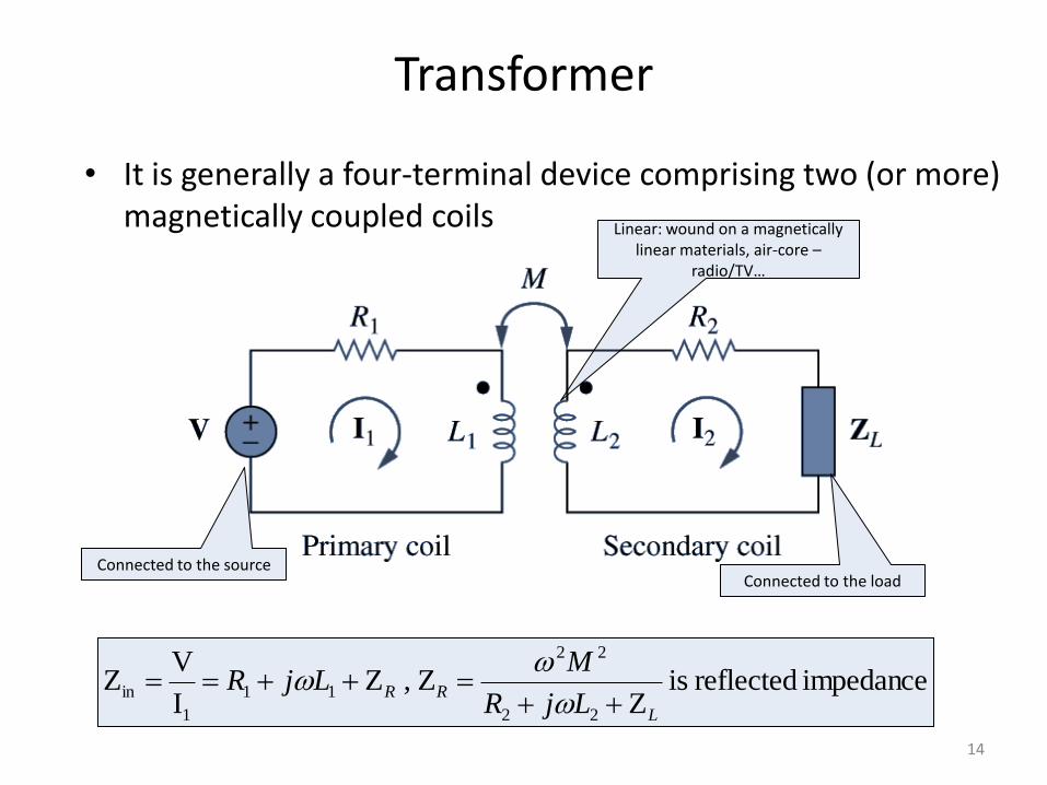
Transformer
• It is generally a four-terminal device comprising two (or more) magnetically coupled coils
impedance reflected is Z
Z, ZI
VZ
22
22
11
1
in
L
RRLjR
MLjR
Connected to the source Connected to the load
Linear: wound on a magnetically linear materials, air-core –
radio/TV…

15
Linear Transformer: Example
Example 3
In the circuit below, calculate the input impedance and current I1. Take Z1=60-j100Ω, Z2=30+j40Ω, and ZL=80+j60Ω.
Ans: A1.1135.0I ;1.5314.100Z 1in

16
Ideal Transformer
• An ideal transformer is a unity-coupled, lossless transformer in which the primary and secondary coils have infinite self-inductances.
Ideal Transformer (a) and Circuit symbol (b)
nN
Nn
N
N 1
I
I
V
V
2
1
1
2
1
2
1
2
V2 > V1→ step-up transformer
V2< V1→ step-down transformer
17
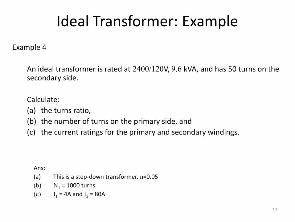
Ideal Transformer: Example
Example 4
An ideal transformer is rated at 2400/120V, 9.6 kVA, and has 50 turns on the secondary side.
Calculate:
(a) the turns ratio,
(b) the number of turns on the primary side, and
(c) the current ratings for the primary and secondary windings.
Ans:
(a) This is a step-down transformer, n=0.05
(b) N1 = 1000 turns
(c) I1 = 4A and I2 = 80A

18
Applications: Isolation device
• Transformer as an Isolation Device to isolate ac supply from a rectifier

19
Applications: Matching device
• Transformer as a Matching Device
Using an ideal transformer to match the speaker to the amplifier
Equivalent circuit

20
Applications: Example
Example 5
Calculate the turns ratio of an ideal transformer required to match a 100Ω load to a source with internal impedance of 2.5kΩ. Find the load voltage when the source voltage is 30V.
Ans: n = 0.2; VL = 3V

Lecture 11 AC Circuits Frequency Response

Appendix

23
Applications: Power distribution
• A typical power distribution system