Embed Size (px)
Citation preview

1. Importance of Oxide Scale during Hot Rolling andon Product Quality
In the hot strip mill, the slab is brought to temperature inthe reheating furnace and discharged for rolling. To breakthe primary scale, the slab is passed through a slab descalerbefore the reversing roughing mill. A secondary oxide scaleis inevitably formed between successive rolling passes dur-ing hot rolling, which is further removed by high pressurewater jets before the subsequent passes during reversingrolling or before the strip enters the tandem finishing mill.Whether the oxide scale is deformed or fractures, it will in-evitably affect the interaction between tool and workpiecefor several reasons: the thermal conductivity of the oxidescale is significantly less than that of the steel1); fracturedscale can enable direct contact of hot metal with the coldtool2,3); because of the possibility of sliding of the fracturedscale raft due to weakness of the scale/metal interface athigh temperatures4); and because the location of the planeof sliding is determined by the cohesive strength at the dif-ferent interfaces within the multilayer oxide/metal systemand by the stress distribution when delamination within thescale takes place.5)
The oxide scale on the surface of the hot metal is impor-tant for the control of friction and heat transfer when incontact with the roll, as well as influencing the rate of heatloss between rolling deformations under air or water sprays.During multi-pass hot rolling of long products, the magni-tude of the coefficient of friction within the roll bite is vari-able due to the complex pressure-slip variations. A newCoulomb-Norton type friction model for long products andbar sections has been developed recently at Swinden Tech-
nology Centre (Corus RD&T UK).6) Among other assump-tions, the model takes into consideration some complex in-teractions at the stock-roll interface due to the presence ofsecondary oxide scale, as mentioned above. Hence, the dif-ferent modes of scale failure, such as the through-thicknesscracking and the sliding mode, depending on the tempera-ture and steel composition, have been implemented into themathematical model. The friction force occurs either be-tween the roll surface and oxide scale or between the rollsurface, the oxide scale fragments and eventually fresh steelextruded through the scale gaps depending on the relativemagnitude of the shear stresses inside the scale layer and atthe oxide scale/stock interface. An additional point of con-sideration is the demand for increasingly small final thick-nesses of the hot rolled steel strip, approximately 1.2 mmduring conventional rolling and 0.8–1.0 mm for ultra-thinhot rolled strips produced on mini-mills using endlessrolling technology.7) The scale related imperfections formedon upper and lower surfaces of the thin strip affect defor-mation of subsurface layers of the material during rollingwhich become relatively more pronounced during rolling ofthe very thin strips.
Perhaps of greater and growing importance is the roleplayed by the oxide scale in determining the quality of thesurface of the hot rolled product, particularly for flat strip.Unfortunately, it is difficult to make direct observations ofoxide scale behaviour under industrial hot working condi-tions, and not much easier in the laboratory. Irregularly re-moved scale defects are often formed on hot rolled steelstrips, causing an inhomogeneous and dirty appearance.Several technological approaches have been proposed toprevent these defects, such as control of slab temperature or
1533 © 2006 ISIJ
Modelling the Behaviour of Oxide Scale in Hot Rolling
Michal KRZYZANOWSKI1) and John Howard BEYNON2)
1) Department of Engineering Materials, The University of Sheffield, Mappin Street, Sheffield S1 3JD, United Kingdom. E-mail: [email protected] 2) Faculty of Engineering and Industrial Sciences, Swinburne University ofTechnology, Hawthorn, VIC 3122, Australia. E-mail: [email protected]
(Received on April 17, 2006; accepted on August 28, 2006 )
Oxide scale behaviour in thermomechanical processing has been the subject of intensive research forseveral years that allowed development of a finite element (FE) based model to simulate a range of eventsof relevance to the process and to the surface quality of the hot rolled product. Oxide scale failure is pre-dicted taking into account the main physical phenomena such as stress-directed diffusion, fracture and ad-hesion of the oxide scale, strain, strain rate and temperature. The most critical parameters for scale failureare measured during modified hot tensile testing and depend on the morphology of the particular oxidescale, scale growth temperature, and are also very sensitive to the chemical composition of the underlyingmetal. The work integrates finite element analysis with a range of experiments each to provide partial in-sight into oxide fracture, friction, heat transfer, pick-up and descaling, amongst others. An overview of thisresearch is presented, revealing a variety of phenomena of considerable technological importance.
KEY WORDS: oxide scale; finite element modelling; measurements; hot rolling; scale failure; surface quality.
ISIJ International, Vol. 46 (2006), No. 11, pp. 1533–1547
Review

strengthening of water jet descaling.8,9) However, despitethese measures, the reason why a conventional descalercannot always remove the scale before rolling is not clear.As has been shown by the authors, the crack patternsformed in deformed scale after a hot rolling pass to a greatextent influence the effectiveness of subsequent descalingoperations, either mechanical or hydraulic, and at the sametime, the formed patterns themselves depend on the processparameters such as temperature, scale thickness and reduc-tion.10,11) In particular, the scales grown on low carbonsteels at high temperatures cannot be assumed both to beperfectly adhering during hot rolling and to be fully brittle.
The chemical composition of the steel can significantlyaffect the state of the scale in both reheat environments andafter the deformation. It is known that small additions of el-ements with a high affinity for oxygen, such as Ce, Y, Hfand Si, can be very effective in promoting the formation ofan adherent oxide layer that is more resistant to attempts toremove it. The active element can have an influence in ele-mental form or as an oxide dispersoid. There are varioustheories that have been proposed to account for an effect ofactive elements; among of them are enhanced scale plastic-ity, modification to the process of oxide growth, strongerchemical bonding at the interface, and oxide protrusionsinto the metal base which can improve adhesion.12,13) It hasbeen proposed that the active element blocks sites, such asinterfacial dislocations, support diffusion growth at thescale-metal interface and thereby alter both the growthmechanism and the adhesion of the scale.14) Other authorsbelieve that segregation of sulphur to the scale-metal inter-face reduces the adhesion of the scale, and that the effect ofthe element is to scavenge the sulphur present in the alloyand hence improve the intrinsically strong adherence.15)
It is difficult to give a satisfactory explanation to all re-ported experimental observations purely on the basis of theavailable theoretical considerations at this stage of under-standing the ‘solid oxide scale/solid underlying metal’ sys-tem. This work reviews mainly the recent research for oxidescale behaviour under hot rolling conditions starting, never-theless, from already classical observations of high temper-ature oxidation of steels such as take place in componentsfor high-temperature service where oxide scales provide aprotective effect. The work also describes an approach ap-plied by the authors for numerical characterisation of oxidescale behaviour based on a combination of closely linkedexperiments under appropriate operating conditions andcomputer based modelling presenting the surface scale evo-lution during hot rolling of steel in the sequence of rollingand finishing with descaling. The modelling has been ex-tended to provide the basis for detailed investigation ofroll/stock interface behaviour during multi-pass hot rollingoperations. The paper concludes with some recent develop-ments highlighting issues for future work related to under-standing of solid oxide/underlying solid metal adhesion athigh temperatures, its role in scale failure during hotrolling, and also considering aspects of integration of oxidescale control with microstructure of the underlying metalby optimal cooling ahead of entry into the roll gap.
2. High Temperature Oxidation of Steel
According to the Fe–O phase diagram the followingthree kinds of oxides exist at temperatures higher than570°C: wüstite (FeO), magnetite (Fe3O4) and haematite(Fe2O3).
16) However, the diagram only represents equilib-rium conditions while, in hot working, conditions can be af-fected by kinetics. Iron oxidation consists mainly of theoutward diffusion of iron ions and the inward diffusion ofoxygen.17) It has been shown that the formation of wüstiteand magnetite is mainly controlled by the outward diffu-sion, while haematite is formed mainly due to the inwarddiffusion of oxygen.18) Normally, the following three typesof rate are observed in high temperature oxidation: para-bolic, linear and intermediate.19,20) Oxidation obeys a para-bolic rate law when the rate controlling step is diffusionwithin the oxide. If the rate controlling step is either themetal surface or the phase boundary interface reaction, thenthe oxidation is described by a linear law. The logarithmicor exponential rate can represent the initial stages of oxida-tion or low temperatures rates. The presence of alloying el-ements in steel also significantly modifies the full range ofoxides that might be possible at a particular temperature.Carbon, for instance, can facilitate or hinder the transportof diffusing ions, thereby increasing or decreasing the oxi-dation.21,22) Carbon diffuses to the scale/metal interface andreacts with iron oxide, evolving CO gas and creating gaps.In high carbon steels at high temperatures, through-thick-ness cracks can occur due to gas pressure in the gaps allow-ing access to the core for the gas atmosphere and, hence, in-creasing the oxidation rate. If there are no cracks formed inthe scale, the stabilized gaps can hinder the outward diffu-sion of iron ions and decrease the oxidation rate.
As has been summarised in a review on high temperatureoxidation, the main effect of alloying elements less noblethan iron on the oxidation, such as aluminium, silicon andchromium, is the formation of a protective layer at thescale/metal interface enriched in alloying elements.23) Forsuch steels, initially the oxidation kinetics are parabolic andthen deviate from the parabolic law as the protective layer,rich in alloying elements, becomes established. However,aluminium, as an alloying element, can increase the tem-perature of wüstite formation and thus can contribute to-wards oxidation resistance.24) Among the three elements,silicon acts as the most protective element, chromium theleast. Nickel and copper are more noble elements than ironand should be rejected at the scale-base metal interface. Inaddition, the iron matrix of such alloys is selectively oxi-dized.25) However, nickel, for instance, does not diffuse rap-idly into the core since the diffusion coefficient of nickel iniron is low. Instead, its concentration at the interface be-comes higher than in the bulk of the metal. For example,Fe–Ni alloy containing only 1.0 wt% Ni and oxidized inoxygen at 1 000°C exhibited significant nickel enrichmentat the surface, about 70 wt%.26) The selective oxidation ofiron and concentration of nickel in the thin layer results ininterpenetration of the oxide scale and metal that producesan additional mechanical oxide-metal bond which increasesthe oxidation resistance. If the diffusion coefficient of thealloying element is higher than the oxidation rate, the con-centration of the element increases, mainly within the bulk
ISIJ International, Vol. 46 (2006), No. 11
1534© 2006 ISIJ

rather than at the surface of the metal. However, some ofthese elements, for instance copper in the iron alloy con-taining 2 wt% Cu, can concentrate at the surface promotingformation of the interlocked scales similar to those formedon nickel alloys.27) Manganese can substitute for iron inwüstite and magnetite.28) It has also been observed thatmanganese together with silicon can combine with ironoxide to develop formations of iron-manganese-silicate inthe oxide scale of the silicon killed steels.29)
The high temperature oxidation of steel has been studiedextensively mainly for the cases of room and elevated tem-peratures such as take place in components for high-tem-perature service where oxide scales provide protection.30) Incontrast, the microstructure of oxides has not been well de-scribed. The results of an application of electron back scat-tered diffraction (EBSD) to the detailed investigation of mi-crostructure and microtexture of oxide scale formed onpure iron, low carbon and Si steel have been reported re-cently.31,32) Based on the Kikuchi diffraction patterns, imagequality (IQ) maps coupled with orientation imaging maps(OIM) were analysed to describe both orientation and shapeof grains forming wüstite, magnetite and haematite layers.Despite different texture and grain size of the substrate,wüstite exhibited a columnar cell structure with a texturetowards scale growth direction normal to the sample sur-face for all specimens. Magnetite was identified as a cubiccell type microstructure having a �001�//GD texture (GDstands for the growth direction of oxide normal to the sam-ple surface) while hematite formed as a very thin wedgeshape layer on the top of the oxide scale. At the interfacebetween wüstite and pure iron, small granular type grainsof wüstite are observed (Fig. 1).32) It can be assumed thatthese wüstite grains are formed in the initial stage of thehigh temperature oxidation. No crystallographic relation-ship between substrate texture and iron oxide texture wasestablished in this research. It seems the microstructure ofscale layers depends mainly on the content of alloying ele-ments rather than microstructure of the substrate. For exam-ple, silicon has a strong effect on the microstructure of the
oxide scale layer in high temperature oxidation. It allowsthe formation of the mixture of wüstite and fayalite(Fe2SiO4) on the substrate surface covered by the relativelythick haematite layer having a bamboo type microstructureduring oxidation of 2 wt% Si steel at 950°C. The same oxi-dation of steels containing 0.4 and 0.98 wt% of Si allowedrather for formation of magnetite, wüstite and the compos-ite of wüstite and SiO2.
3. Making Measurements of Oxide Scale Behaviourunder Hot Working Conditions
Making observations of oxide scale behaviour under in-dustrial conditions is extremely difficult and is not mucheasier in the laboratory. Standard methods of measurementon their own are not feasible or adequate for this purpose.A single experiment has not been found that is capable ofrepresenting the full range of phenomena. Instead, a rangeof techniques, each providing a partial insight, has been de-veloped by different authors.
3.1. Laboratory Rolling Experiments
It has been shown during laboratory hot rolling tests oflow carbon steel slabs that different thicknesses and struc-tures of the oxide scales resulted in significantly differentstates of the oxidised slab surface after the deformation,ranging from continuous oxide scale layer adhering to themetal surface to severely cracked scales with signs of metalextrusion through the gaps in the scale under the roll pres-sure.33) Different thicknesses and structures of the oxidescales resulted in different crack width, crack spacing andextent of fresh steel flow through the gaps during hotrolling, as a function of temperature and rolling reduction.The direct measurement of scale temperature within sec-ondary oxide scale proved to be difficult because of the sig-nificant temperature gradient across the scale thickness dur-ing conventional hot rolling tests. In hot ‘sandwich’ rolling,two slabs welded together at the leading edge are angledapart during furnace reheating with cracked natural gas
ISIJ International, Vol. 46 (2006), No. 11
1535 © 2006 ISIJ
Fig. 1. The IQ map and the GD inverse pole figures (IPFs) of the wüstite layer: (a) the microstructure of the initial stageand (b) the grain growth stage; (c) IPF at the initial stage and (d) at the growth stage.32)

protection to allow formation of a thin oxide scale on thesurfaces. After reheating, the slabs are closed together withthe two scale layers trapped between the slabs, which canthen be rolled at different temperatures and reductions.34)
The temperature gradient across the oxide scale betweenthe slabs is negligible during hot rolling and the tempera-ture history can be reliably measured by means of an in-serted thermocouple. It makes the ‘sandwich’ rolling testdifferent from the conventional one, where the surfaceoxide scale is undergoing severe chilling by the roll. As canbe seen in Fig. 2, the scale behaviour during hot ‘sandwich’rolling of plain carbon steel is strongly sensitive to rollingtemperature and reduction. Two extreme cases were ob-served during the rolling tests: when the scale exhibited nocracking and when scale cracks, orientated transverse to therolling direction, appeared after the rolling pass. It was con-cluded that during conventional hot rolling with low rollingspeed, which is more typical for laboratory rolling condi-tions and industrial plate rolling, the scale chilling duringthe rolling pass is significant and the scale temperature caneasily fall below the critical level for scale cracking, eventhough the bulk temperature of the slab is above that level.The contact time with the rolls for industrial hot striprolling is much shorter, as the rolling speed is significantlyhigher, and the oxide scale can remain at high temperatures
during the rolling pass, exhibiting no cracks after rolling.In attempting to reduce the concomitant thermal effects
and to simulate the behaviour of oxide scale during rollingat low temperatures when the low carbon steel scales ex-hibit significantly brittle behaviour, a brittle lacquer hasbeen applied on the surface of lead slabs, which have beenrolled at room temperatures.35) The lacquer mimics a brittleoxide scale on a hot working metal (lead is hot worked atroom temperature) without temperature gradients. For therelatively thick scales (about 100 mm) and for similarrolling reductions the crack patterns of the oxide scales andthe lacquers were similar. In the central area of the slab sur-face, the cracks produced were narrow, with no visible fullextrusion of fresh metal into the gaps. In contrast, near theedge of the slab the cracked pieces were much larger andcurved, and the major cracks were filled with extrudedmetal. The similar crack and lacquer patterns suggest thatthe wide cracks observed at the edges of the slab arisemainly because spread and cracking in the edge areas be-fore entry into the roll gap, while the effect of temperaturegradient across the slab width is secondary.
Furthermore, by interrupting the rolling part way throughthe length of the specimen and neglecting the effects of de-celerating the rolling as one does so, it is possible to ob-serve the evolution of the scale as it passes through the rollgap (Fig. 3).10) Such stalled hot rolling tests have been con-ducted with the aim of verifying the main points of thescale behaviour predicted using numerical analysis basedon finite element (FE) modelling, described below.
3.2. Tensile Testing
As the slab enters the roll gap, it is drawn in by frictionalcontact with the roll, which is moving faster than the stockat that point. This inevitably produces a longitudinal tensilestress in the stock surface ahead of contact with the roll. Itis this tensile stress that can lead to fracture of the scaleprior to roll contact, and therefore the uniaxial tensile testcan provide much valuable information on the behaviour ofoxide scale that is relevant to hot rolling conditions. Tensiletests have been carried out under controlled atmosphereconditions, with oxidation allowed only at elevated temper-
ISIJ International, Vol. 46 (2006), No. 11
1536© 2006 ISIJ
Fig. 2. Oxide scale behaviour during hot sandwich rolling ofC–Mn steel slabs; Scale thickness �100 mm, rollingspeed 0.14 m/s.3)
Fig. 3. Scanning electron micrograph showing oxide scale crack pattern obtained using stalled hot rolling testing (a) andlongitudinal component of total strain predicted at the same area (b) illustrating the slab spread at entry into theroll gap.

ature, followed by tensile deformation either at that temper-ature or a different one, under displacement control.4,5)
These tests revealed two types of accommodation by theoxide scale of the deformation of the underlying steel sub-strate (Fig. 4). At lower temperatures, the oxide scale frac-tured, usually in a brittle manner, with the through-thick-ness cracks triggering spallation of the oxide scale from thesteel surface. At higher temperatures, the oxide scale didnot fracture, rather it slid over the steel surface, eventuallyproducing delamination of the scale.
By assuming the transition temperature range, when theseparation load within the scale fragments is less than theseparation load at the oxide/metal interface at low tempera-ture and exceeded by it at high temperature, it is possible tomodel transfer from one oxide scale failure mechanism toanother. The temperature of transition between these twotypes of failure was sharp and very sensitive to steel chemi-cal composition. It has been demonstrated experimentallyand modelled numerically that small differences in chemi-cal content, mainly of Si (0.18 wt% for steel 1 and0.36 wt% for steel 2) and Mn (0.79 wt% for steel 1 and1.33 wt% for steel 2), for the mild steel containing0.02–0.07 wt% Ni and 0.08–0.14 wt% Cu, can be the rea-son for the different modes of scale failure in tension.36,37)
To satisfy the differences between the states of the oxidescale after tension it was assumed that the transition tem-perature for the second steel grade is about 100 K higherthan that for the steel 2, and that the separation loads bothwithin the oxide scale and for the oxide/metal interface ex-ceed the corresponding loads for the first steel. As has beenmentioned earlier, the alloying elements have different in-fluences on the oxidation rate in reheat environments. How-ever, the effect of steel chemistry on the growth of the scaleis more pronounced for the longer times of oxidation typi-cal for reheating processes, but not for the secondary oxidescale growing during short time after the first descaling be-tween subsequent rolling passes. Thus, the differences inchemical content for these two low carbon steels did notproduce significant differences in oxide scale growth for thechosen time intervals.
The mode of failure for Mn–Mo (0.34 wt% C, 0.23 wt%Si, 1.28 wt% Mn, 0.039 wt% S, 0.022 wt% P, 0.17 wt% Cr,0.12 wt% Ni, 0.17 wt% Cu and 0.24 wt% Mo) and Si–Mn(0.57 wt% C, 1.90 wt% Si, 0.79 wt% Mn, 0.008 wt% S,
0.01 wt% P, 0.18 wt% Cr, 0.08 wt% Ni, 0.16 wt% Cu andless than 0.02 wt% Mo) steel oxide scales was confinedonly to through-thickness cracks in tension within the hotrolling temperature range from 783 to 1 200°C. Thisfavours the assumption that the presence of alloying ele-ments such as manganese, molybdenum and silicon resultsin strengthening of the oxide/metal interface at high tem-peratures compared with mild steel. A stainless steel, con-taining 0.025 wt% C, 0.47 wt% Si, 1.44 wt% Mn, 0.034wt% S, 0.031 wt% P, 18.4 wt% Cr, 9.2 wt% Ni, 0.26 wt%Cu and 0.47 wt% Mo, had also shown only through-thick-ness mode of failure. For this steel, the oxide formed at1 074°C for 800 s was less than 10 mm thick and thethrough-thickness cracks presented within the scale afterthe test were only visible under scanning electron mi-croscopy.37) There is a high probability that sliding of theoxide scale during tension would be observed for any of thesteel grades at higher temperatures, outside the testedrange. It is clear that the observed differences in deforma-tion behaviour are much larger than would be expectedfrom differences in oxidation. The chemical content of theunderlying steel influences the fracture energy of the scaleand its adherence to the metal surface, and both are re-flected in the observed differences in scale failure. Thisraises important issues where further research work isneeded. The direct measurement of the scale-metal separa-tion loads coupled with physically based modelling wouldallow the observed effects to be more predictable.
A modification to the simple tensile test was developedin an effort to measure directly the loads involved in thesetwo types of failure.38) A hollow tensile sample was deliber-ately split in two, with a central ceramic dowel providingalignment with the two halves pressed together during oxi-dation. Upon deformation, the two steel halves came apartreadily, the fracture or sliding of the oxide scale then beingmeasured by the load cell. To separate the oxide scale effectfrom any background resulting from bonding and friction,unoxidised split-sample measurements were subtracted toprovide a good measure of the fracture and sliding forces,which were in the range 0.15–1 kN. Figure 5 schematicallyillustrates the different separation loads measured duringdifferent modes of oxide failure under the testing proce-dure. For the first mode, failure occurs with through scalethickness cracking. In this case, the separation loads within
ISIJ International, Vol. 46 (2006), No. 11
1537 © 2006 ISIJ
Fig. 4. Two different modes of oxide failure observed in hot tensile testing of low carbon steel for 2.0% strain at 0.2 s�1
strain rate at 830°C (a) and 900°C (b). Schematic representation of the effect of temperature on separation loadsfor the scale/metal system deduced from the testing (c).

the oxide scale are registered. For the second one, the tan-gential separation loads at the scale-metal interface are reg-istered while the oxide scale is sliding along the scale-metalinterface. The level of load causing failure of steel oxidescale for both modes of failure is illustrated in Fig. 6. Themeasured loads have been recalculated in terms of strainenergy release rate to be introduced in the oxide scalemodel.
3.3. Hot Four-point Bend Testing
It has been shown that the four-point bend testing can becoupled with inverse calculations for determination of me-chanical properties of the oxide scale at the temperaturerange relevant to hot rolling conditions.39) In this testing, ameasuring pin was connected to a displacement transducermeasuring the deflection at the centre of the specimen.Only the bottom surface of the sample, which was in ten-sion during bending, was oxidised. The device allowed oxi-dation for a given time at a prescribed temperature in a con-trolled atmosphere simulating the thermo-chemical historyof the strip in a rolling mill. As in the case of split tensiletesting, in the hot four-point bend testing two differentmeasurements are performed for each temperature. Thefirst measurement is for a non-oxidised sample followed bya second one on an oxidised specimen under the same con-ditions, the former serving as a reference from which thedifference brought by the oxide scale is determined. Thesame two types of steel scale failure in tension have beenobserved in these tests, in qualitative agreement with thoseobserved earlier during tensile testing. At temperaturesbelow 700°C, the scale was weaker than the interface,which resulted in through-thickness crack formation fol-lowed by spallation of the scale fragments due to crackingalong the scale-metal interface. At temperatures above750°C, the scale layer was tougher, allowing the crack topropagate along the scale-metal interface, leading tospalling of large pieces of oxide. The merit of this approachwas that it demonstrated the feasibility of determiningoxide scale mechanical properties at conditions relevant tohot rolling.
3.4. Hot Tension–Compression Testing
It has been mentioned that an open gap in the oxide scalemay enable the steel underneath to extrude up under the rollcontact pressure. Once such hot steel makes direct contactwith the roll, the local friction and heat transfer conditionscan be expected to change dramatically. A hot tension/com-pression testing technique has been developed to make di-rect observations of such extrusion under controlled labora-tory conditions.40) A tensile sample with a rectangularcross-section is used to produce a flat specimen withthough-thickness cracks in the surface scale in the sameway as during hot tensile testing of cylindrical specimens.The central section is then cut and compressed between toolsteel anvils to observe extrusion up through the open crack.This technique was developed further to investigate the be-haviour of a range of crack openings, Fig. 7. The unex-pected discovery was made during this testing that narrowcracks could close under this compressive deformation de-pending on the temperature, the scale thickness, the strainrate and the initial crack width.41) The experiments, con-ducted with scales with a range of thicknesses, were con-
ISIJ International, Vol. 46 (2006), No. 11
1538© 2006 ISIJ
Fig. 5. Schematic representation of different separation loadsmeasured during different modes of oxide failure in mod-ified tensile testing.
Fig. 6. Loads registered during two modes of oxide scale failurein tension: through-thickness crack (a) and sliding alongthe interface (b); �, testing with oxidation; �, testingwithout oxidation; �, subtraction of � from �.
Fig. 7. Schematic representation of the hot tension-compressiontest.

firmed using the FE method. Figure 8 shows the effect ofscale thickness on this behaviour.
An important surface quality defect stems from pick-upby the roll of oxide scale from the steel surface, usually insmall patches which then come back around on the roll sur-face and indent into the following metal.42) The roll pick-upeffect is also connected with deformation and failure of theoxide scale during the rolling pass. The fragmentized scalecan be partly spalled from the stock surface, inevitably re-ducing the scale/steel separation force. For these reasonsthe effect should be considered together with the hot rollingand modelled assuming scale failure during hot rolling. Acompression test has been developed recently where onehalf (‘tool’) represents the roll material and the other half(‘sample’) is made from the stock material. The oxide fromthe sample can be picked up by the tool after oxidation incontrolled atmosphere at the desired temperature and com-pression conditions (Fig. 9).43) The sticking phenomenonwas observed during testing at 870°C with the thickness ofthe oxide scale about 50 mm. Figures 9(b), (c) illustrate anoxide scale partly separated from the stock imitation speci-men after the test. At 970°C, the whole oxide scale adheredto the tool during the contact and pulled away, exhibitingthe high sensitivity of the observed effect to temperature.
4. Finite Element Modelling of Oxide Scale Behaviour
The oxide scale model is usually a micro-part of a morecomplex macro-FE model. Corresponding linking of mod-elling scales is a necessary stage for prediction of scale be-
haviour during modelling of both mechanical testing andtechnological operations. When quality of surface finish isthe subject of the numerical analysis or fine mechanisms offormation within a few microns thick surface layer duringthe rolling of stainless steel is under consideration, theoxide scale model has the capacity to include very fine fea-tures such as multi-layer scale, voids or a complicated pro-file of the scale/metal interface. To link ‘macro-’ and‘micro-’ scales of modelling, the model is reduced to asmall segment at the stock-roll interface. The boundaryconditions for the small segment are taken from the macro-model. The FE mesh near the interface is then refined as re-quired; the origin of coordinates is changed by tying it toone of the segment nodes and, finally, the oxide scale frag-ments are introduced on to the metal surface. This proce-dure allows for consideration of the fine morphological fea-tures of the scale and the scale/metal interface while, at thesame time, reducing the number of elements under consid-eration (Fig. 10).44) The approach also enables a thin film tobe introduced on the roll surface, which can also be definedas oxide scale on the roll surface.
4.1. Fracture, Ductile Behaviour and Sliding
The oxide scale is simulated as comprising numerousscale fragments joined together to form a scale layer10–100 mm thick, covering the raft length of about
ISIJ International, Vol. 46 (2006), No. 11
1539 © 2006 ISIJ
Fig. 8. Change of the gap in the oxide scale during compressionpredicted for the different initial scale thicknesses at atemperature of 1 000°C.
Fig. 9. Schematic representation of the hot compression test set-up (a) and photographs illustrating the oxide scale partlyseparated from the specimen (c) and transferred to thetool (b) after being in contact during compression test at870°C.
Fig. 10. Linking of ‘macro-’ and ‘micro-’ scales of modelling: 1, macro model run; 2, reduction to characteristic size; 3,4, FE mesh refinement near the interface; 5, change of coordinate origin and introduction of the oxide scale frag-ments.

20–50 mm. The length of each oxide scale fragment is cho-sen to be less than the smallest spacing of cracks observedin the experiments, enabling prediction of representativecrack spacing and distribution of cracks along the length ofthe raft due to both longitudinal tension and contact withthe roll (Fig. 11). Oxide scale failure is predicted by takinginto account the main physical phenomena such as stress-directed diffusion, fracture and adhesion of the oxide scale,strain, strain rate and temperature. The main mathematicalassumptions of the model related to oxide scale and imple-mented properties of materials have been described else-where.10,36,37,45,46) The finite element model is rigorouslythermo-mechanically coupled and all the mechanical andthermal properties were included as functions of tempera-ture. The radiative cooling of heated surfaces was simulatedby prescribing the energy balance for the boundary surface.The scale and metal surface were assumed to be adheringwhen they were within a contact tolerance distance. Themost critical parameters for scale failure have been meas-ured during both tensile and modified hot tensile testing(see above) and depend on the morphology of the particularoxide scale, scale growth temperature and, very sensitively,the chemical composition of the underlying steel.38)
The macro-parts of the FE model that compute the tem-perature, strain, strain rate and stress in the tensile speci-men during testing have been adjusted according to theconfiguration of the tensile test. The micro-part of the FEmodel related to the oxide scale on the gauge section of thespecimen and was validated during the procedure (Fig. 12).Matching the predicted and measured loads allows thestrain energy release rate to be determined, which is a criti-cal parameter for prediction of crack propagation within thescale or along the scale/metal interface (Fig. 13). Steel ox-ides show both brittle failure at temperatures below about800°C and signs of ductile fracture at higher temperatures.For the former, the critical strain for failure is implementedinto the model, while the J-integral is used as a parametercorresponding to the strain energy release rate for consider-ation of ductile scale failure. Determination of the crack
length is based on increment number and deactivation ofthe separation forces based on the crack length and J-inte-gral value. It has been assumed that no-singularity model-ling near the crack tip is applicable, with a quarter-pointnode technique and only one contour for the J-integralspecified for each interface. In the virtual crack extensionmethod only derivatives of elements of the inverse JacobianJ-1 and of the determinant of the Jacobian [J] are involved(where the symbols have their usual meaning):
.........(1)
This method, comprehensively described elsewhere,47) ap-peared to be easier to apply for simulation of crack propa-gation along the interfaces. The MSC/MARC 2000 com-mercial finite element code was used to simulatemetal/scale flow, heat transfer, viscous sliding and failure ofthe oxide scale during hot rolling, assuming the plane straincondition. The release of nodes was organized using user-defined subroutines in such way that the crack length is de-termined based on the increment number then, according tocrack length, the boundary conditions are deactivated bycalling a routine for a specific node number.
4.2. Scale Evolution during Hot Rolling, MultilayerScales
The evolution of the steel’s secondary oxide scale duringhot rolling starts already at entry into the roll gap. The scaleis then subjected to further significant changes both withinthe roll gap under the roll pressure and at the exit zone, fol-lowed by its failure during hydraulic and mechanicaldescaling operations. Some of these phenomena have beendiscussed elsewhere10,11,37) and are briefly summarized inthe next following sections.
Longitudinal tensile deformation ahead of entry into theroll gap, coupled with bending at the moment of grippingwith the roll, induce cracking in the oxide scale at this entryzone. The initial stock temperature can be considered to be
δ δ σ δη
W Wu
dVij jki
kV
e | J | J [J]� � �1 0
0
∂∂
∫
ISIJ International, Vol. 46 (2006), No. 11
1540© 2006 ISIJ
Fig. 11. Hot strip rolling model: representation of FE mesh,oxide scale with randomly distributed pre-existingcracks (a) and equivalent total strain predicted withinthe cross-section of the strip after the first rolling passfor the different pre-existing crack spacing (b and c);strip thickness 1 mm; oxide scale thickness 100 mm; re-duction 30%.
Fig. 12. Longitudinal strain contours predicted for two differentmodes of oxide failure during validation of the oxidescale model simulating hot tensile testing of low carbonsteel for an overall 2.0% tensile strain at a strain rate of0.2 s�1 and 830°C (a) and 900°C (b).

a crucial factor for oxide scale failure. When the initialstock temperature is in the low temperature range of brittleoxide and strong oxide/metal interface, a longitudinal ten-sile strain in the stock surface ahead of contact with the rollcan result in through-thickness crack formation (Fig.14(a)). At higher temperatures, interface sliding can have asignificant role in relaxation of stresses within the scale,coupled with the lower level of longitudinal stresses at thestock surface layer for the higher temperature. As a result,through-thickness cracks at entry into the roll gap mighthave not occurred, so the scale would come into the roll gapwithout pre-formed cracks (Fig. 14(b)). There is a lowerlimit of the oxide scale thickness, for a particular steelgrade and rolling parameters, beneath which the scalecomes into the roll gap without through-thickness cracks.The longitudinal tensile stress at entry into the roll gap can
favour through-thickness cracks in the scale when the initialrolling temperature is low and the oxide scale thickness ex-ceeds its lower limit. The breaking up of the scale at themoment of the roll gripping contributes to the scale failurefor this temperature range (Fig. 15).
The observations using scanning electron microscopy(SEM), back-scattered electron imaging (BEI) and electronback-scattered diffraction (EBSD) allow for configurationof the FE model to reflect precisely the characteristic mor-phological features, such as different oxide sub-layers,voids, roughness of the interfaces, the proportion of eachlayer at different temperatures, oxidation times and steelcomposition.11,44) Figures 16(a) and 16(b) show some ofthe complexity of oxide scale on the surface of carbon steel,which may comprise two or three oxide types, be porous,have large scale voids, and have a crystal size that is of the
ISIJ International, Vol. 46 (2006), No. 11
1541 © 2006 ISIJ
Fig. 13. Modified tensile testing: scanning electron micrograph showing end view of oxide scale fractured at 1 050°C (a);results of finite element modelling showing ductile fracture during the test predicted using the J-integral approach(b); measured (c) and predicted (d) load at the head of the specimen deformed at 975°C and 0.2 s�1 strain rate.
Fig. 14. Distribution of longitudinal stress component predicted at the moment of entering into the roll gap at an initialtemperature of 800°C (a), note the crack opened up in the oxide scale ahead of contact with the roll, and at aninitial temperature of 1 100°C (b) where there is no cracking of the oxide scale.
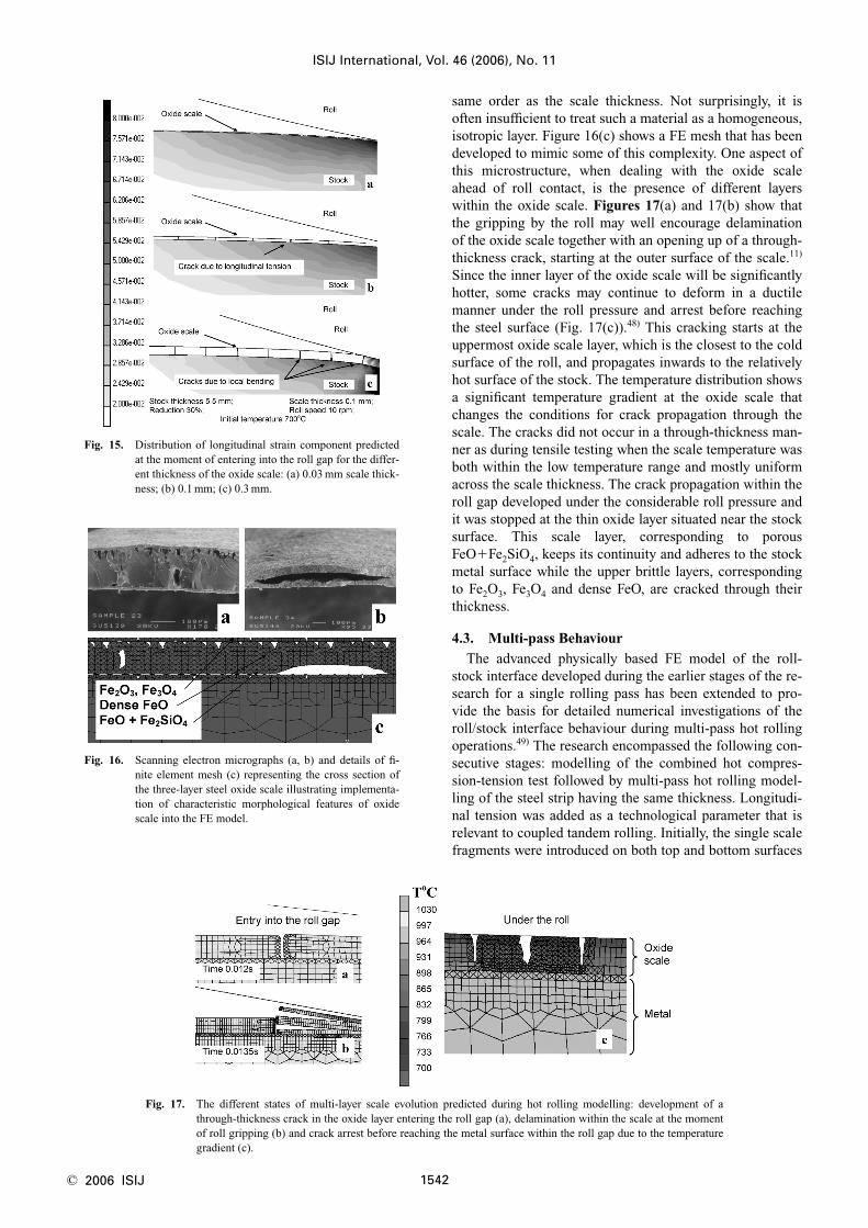
same order as the scale thickness. Not surprisingly, it isoften insufficient to treat such a material as a homogeneous,isotropic layer. Figure 16(c) shows a FE mesh that has beendeveloped to mimic some of this complexity. One aspect ofthis microstructure, when dealing with the oxide scaleahead of roll contact, is the presence of different layerswithin the oxide scale. Figures 17(a) and 17(b) show thatthe gripping by the roll may well encourage delaminationof the oxide scale together with an opening up of a through-thickness crack, starting at the outer surface of the scale.11)
Since the inner layer of the oxide scale will be significantlyhotter, some cracks may continue to deform in a ductilemanner under the roll pressure and arrest before reachingthe steel surface (Fig. 17(c)).48) This cracking starts at theuppermost oxide scale layer, which is the closest to the coldsurface of the roll, and propagates inwards to the relativelyhot surface of the stock. The temperature distribution showsa significant temperature gradient at the oxide scale thatchanges the conditions for crack propagation through thescale. The cracks did not occur in a through-thickness man-ner as during tensile testing when the scale temperature wasboth within the low temperature range and mostly uniformacross the scale thickness. The crack propagation within theroll gap developed under the considerable roll pressure andit was stopped at the thin oxide layer situated near the stocksurface. This scale layer, corresponding to porousFeO�Fe2SiO4, keeps its continuity and adheres to the stockmetal surface while the upper brittle layers, correspondingto Fe2O3, Fe3O4 and dense FeO, are cracked through theirthickness.
4.3. Multi-pass Behaviour
The advanced physically based FE model of the roll-stock interface developed during the earlier stages of the re-search for a single rolling pass has been extended to pro-vide the basis for detailed numerical investigations of theroll/stock interface behaviour during multi-pass hot rollingoperations.49) The research encompassed the following con-secutive stages: modelling of the combined hot compres-sion-tension test followed by multi-pass hot rolling model-ling of the steel strip having the same thickness. Longitudi-nal tension was added as a technological parameter that isrelevant to coupled tandem rolling. Initially, the single scalefragments were introduced on both top and bottom surfaces
ISIJ International, Vol. 46 (2006), No. 11
1542© 2006 ISIJ
Fig. 15. Distribution of longitudinal strain component predictedat the moment of entering into the roll gap for the differ-ent thickness of the oxide scale: (a) 0.03 mm scale thick-ness; (b) 0.1 mm; (c) 0.3 mm.
Fig. 16. Scanning electron micrographs (a, b) and details of fi-nite element mesh (c) representing the cross section ofthe three-layer steel oxide scale illustrating implementa-tion of characteristic morphological features of oxidescale into the FE model.
Fig. 17. The different states of multi-layer scale evolution predicted during hot rolling modelling: development of athrough-thickness crack in the oxide layer entering the roll gap (a), delamination within the scale at the momentof roll gripping (b) and crack arrest before reaching the metal surface within the roll gap due to the temperaturegradient (c).

of the thin strip. This was followed by introduction of acontinuous oxide layer on both strip surfaces (Fig. 18). Thepossibility of a co-operative relationship between the for-mation of oxide scale related defects at the upper and lowerfaces and formation of shear zones within the steel strip hasbeen demonstrated numerically for such thin strips. It hasbeen shown that the through-thickness shear zones withinthe material can link between the scale related defects onboth the upper and lower strip surfaces. The observed effectis more pronounced for thin or ultra-thin hot rolled strips,such as 0.8–1.0 mm in thickness, with relatively thick oxidescales (a situation that one would try to avoid in industrialpractice). The modelling results exhibited that the oxidescale after the first rolling pass enters the second rollingpass having been deformed, fragmentised and partly spalledfrom the metal surface. These effects are progressively in-creased during the second rolling pass. It was also observedthat formation of the scale related shear zones within thestrip volume takes place mainly during the second rollingpass (Fig. 18(d)). The distorted elements were determinedas elements having internal angles that deviated from 90°by more then 15°. The scale related shear zones remainwithin the strip volume after spallation of the scale frag-ments. A single scale fragment remaining on the strip sur-face after the first rolling pass can influence formation ofthe shear zones during consecutive rolling passes. Longitu-dinal tension contributes to the formation of the observed
shear zones. More work, particularly experimental, shouldbe done to characterize the scale related effect of shearzone formation that has been demonstrated numerically. Itis important because there are experimental prerequisitesthat shear deformation can lead to formation of shear zonesin the metal’s microstructure.50)
4.4. Descaling Simulation and Surface Quality
Major effort has been made in recent years by re-searchers trying to find ways to maximize descaling effec-tiveness. The design of any efficient spray-based descalingsystem depends primarily on the magnitude of the descal-ing force necessary to remove the oxide scale. The oxidescale can be removed by a combination of shear force Fs
and vertical force Fv created by the water rebounding offthe strip underneath the edge of the scale fragment. There isalso the force arising from the differential thermal contrac-tion of scale and metal induced by the cold water, and theangular force Fa tumbling the oxide scale off the metal sur-face (Fig. 19). The forces to a large extent depend on thestate of the oxide scale to be removed in the consecutivedescaling operation. The oxide scale fragments that werepartly spalled during hot rolling will inevitably be easier toremove, hence reducing the required descaling force.51) Themechanism of development of the interface crack that leadsto spallation of a scale fragment is illustrated in Fig. 20.The cracking starts at the scale-metal interface at the exit
ISIJ International, Vol. 46 (2006), No. 11
1543 © 2006 ISIJ
Fig. 18. Modelling of two-pass hot rolling: model setup (a); representation of the initially continuous oxide scale on bothupper and bottom strip surfaces (b); distribution of equivalent plastic strain (c) and distorted elements (d) withinthe cross section of the strip after consecutive rolling passes; strip thickness 1 mm; scale thickness 0.1 mm.

from the roll gap when the scale is fragmented during therolling pass. Both the longitudinal tension, extensively de-veloped at the surface layer of the stock at the exit zone,and the roll pick-up contribute towards the separation.11)
The scale fragments in the roll gap are of different length.As can be seen in Fig. 21, where consecutive stages of thescale spallation are shown, the shorter scale fragment hasbeen transferred to the roll surface while the longer one re-mains adhered to the surface of the stock. This favors theconclusion that shorter scale fragments can be more easilyremoved from the stock surface than longer ones, and thatfragmentation of the secondary scale during a rolling passshould make a subsequent descaling operation more effi-cient. This is in agreement with earlier results on mechani-cal descaling, where it was shown that relatively thicker andshorter scale fragments can be more easily removed fromthe metal surface.52) However, from the point of view ofsurface finish improvement for hot rolling, the through-thickness gaps formed within the oxide scale should besmall enough to prevent extrusion of the hot metal and for-
mation of bumps on the rolled metal surface (Fig. 22).This work suggests two means of surface quality im-
provement for the hot rolled product. The first is maintain-ing the oxide scale on the metal surface during the processas a continuous, uncracked layer. The second is completeremoval of the scale from the surface of the stock duringdescaling operations. For the second, increasing the descal-ing effectiveness is becoming a priority issue. Althoughachievement of these two extreme cases is difficult in prac-tice, the numerical analysis showed that maintaining the op-timal temperature on the surface of the stock at entry intothe roll gap is essential for both cases. It has been discussedabove that if the scale reaches the roll gap at high tempera-ture, which is specific for the underlying steel composition,or if the thickness of the scale is beneath the lower limitwhen the stress for through-thickness crack propagation ex-ceeds the yield stress assumed for the oxide scale, then theoxide scale will be able to deform in a ductile manner andwill not fail by through-thickness cracking. If the oxidescale comes to the roll gap in the low temperature range,i.e. when the scale-metal interface is strong enough totransmit the shear stress to the oxide scale at entry into theroll gap, the probability of scale failure during the rollingpass is high. In this case, additional fragmentation of thescale is beneficial from a descaling point of view. Figure 23illustrates the effect of water jet impact on the oxidizedstock surface ahead of roll contact. The effect of the waterjet impinging on the hot steel surface with its continuous,
ISIJ International, Vol. 46 (2006), No. 11
1544© 2006 ISIJ
Fig. 19. Fragmentized, partly-spalled oxide scale predicted afterthe rolling pass and schematic illustration of forces con-tributing towards hydraulic descaling.
Fig. 20. Formation of the scale separation from the strip surfacepredicted at the exit from the roll gap for two consecu-tive time steps.
Fig. 21. Different consecutive stages of scale failure predicted atexit from the roll gap. Note transfer of the shorter scalefragment to the roll surface while the longer ones stillremain adhered to the stock surface.
Fig. 22. Gaps within the oxide scale formed under the roll pressure during the rolling pass; note different sizes of thegaps due to their different origins.

uncracked oxide scale was only thermal and was modelledby applying transient boundary conditions for heat transferon the basis of available experimental results.53) About3.4 ms after the application of the water cooling, the oxidescale exhibited through-thickness cracking as a result ofstresses caused by the different thermal contraction of thescale and the underlying steel. Some cooling of the underly-ing steel surface layer is also visible at the places withoutoxide scale. However, assuming that in practice the scalelayer entering the roll gap is initially continuous, the effectcan be minimised. The crack width should not exceed somecritical level before entering the roll gap to prevent metalextrusion into the gap under the roll pressure.41)
5. Future Issues
The behaviour of oxide scale on the surface of hot metalundergoing thermomechanical processing presents a richvariety of phenomena of great technological importance.This research has already found industrial application,6,54)
yet there remains much to be done. In particular, integrationof oxide scale control with microstructural development ofthe underlying metal. It has already been discussed thatmaintaining the optimum temperature of the surface of thestock at entry into the roll gap is essential for scale failureand subsequent descalability, which inevitably affect thesurface quality of the product. Such temperature controlshould be integrated with the temperature control of thebulk metal, hence considering the surface and microstruc-tural development together.
Another issue is the effect of the chemical compositionof the underlying steel on oxide scale evolution, an effect isclosely linked to oxide scale adhesion. Adhesion is one ofthe most important factors affecting oxide scale behaviourduring hot metal forming operations. It influences the oxidescale failure mode and hence the surface quality of the finalsteel product. Prediction of adhesion gives the basis for bet-ter control of surface finish during hot metal forming opera-tions. The main physico-chemical processes responsible forscale adhesion at high temperature are still under discus-
sion55,56). One of the issues is whether the adhesion theoryfor solid oxide/liquid metal systems can be extended tosolid oxide/solid metal systems. Making relevant measure-ments for such systems at high temperatures is extremelydifficult. The high temperature tensile test has been used toestimate scale adhesion for temperature conditions similarto those of hot rolling.57) It was observed earlier for lowcarbon steels that the transition temperature from one modeof scale failure in tension to another one is highly sensitiveto the chemical composition of the steel.36,37) Similar behav-iour of the cracking-sliding transition in tension has beenobserved recently for the different modelled iron alloys(Fig. 24).57) Pure iron and also Fe–4at%Mo and Fe–4at%Tialloys were used to study the influence of chemical compo-sition on oxide scale adhesion. Decreasing the number ofalloying elements to two facilitates the understanding therole of a particular additive. The type and amount of the al-loying elements were chosen to be similar to previouslystudied solid oxide/liquid metal systems. The experimentalresults showed displacement of the transition temperaturetowards higher temperatures for the alloys in the sequenceFe→Fe/Mo→Fe/Ti. Since both Mo and Ti do not decreasethe strength of the corresponding oxides,58) simulation ofsuch displacement has been obtained by implementing itinto the oxide scale finite element model as a relative in-crease of the separation loads for the oxide/metal interface,which means an increase in relative adhesion between the
ISIJ International, Vol. 46 (2006), No. 11
1545 © 2006 ISIJ
Fig. 23. Progressive temperature distributions at the surface layer of the stock entering the roll gap. Note scale crackopening after application of water jet cooling and crack closure after removal of the water cooling.
Fig. 24. Two modes of oxide scale failure: ‘cracking’ and ‘slid-ing’ observed for pure Fe (a, c) and Fe–4at%Mo (b, d)after high temperature tensile testing at 10% strain,0.2 s�1 strain rate and the following temperature:1 000°C (a); 1 200°C (b); 1 100°C (c); 1 300°C (d).

oxide scale and the underlying metal. Similar to the rele-vant scale/liquid metal systems, the assumption has beenmade that the adhesion depends on the probability of chem-ical interaction at the interface, which is expressed throughthe Gibbs energy of possible reactions. The more negativeis the value of the Gibbs energy, the higher is the adhesion.This model was initially proposed for aluminium oxide incontact with liquid metals.59) Later it was expanded to anumber of oxide/liquid metal systems40) and then to ni-tride/liquid metal systems.60) Assuming that the followingreactions take place at the interface,57,61) the scale adhesionof the chosen oxide/metal systems in solid state can also beassociated with a decrease in Gibbs energy of oxidation ofthe alloying elements:
2Fes�O2g�2FeO, DG298°��492 kJ/mol
Mos�O2g�MoO2, DG298°��502 kJ/mol .........(2)
Tis�O2g�TiO2, DG298°��889 kJ/mol
The observed correlation (Fig. 25) supports the key role ofchemical composition for the scale/metal adhesion andshows the sensitivity of the developed experimental tech-nique to registering the relevant differences at high temper-atures. It also indicates that the main assumption of the ad-hesion model developed for solid oxide/liquid metal systemis applicable to solid scale/solid metal oxide systems.
6. Conclusions
The behaviour of oxide scale on the surface of hot metalundergoing thermomechanical processing presents a richvariety of phenomena of great technological importance.Despite considerable complexity, detailed quantitative in-sight has been obtained for representing a wide range of theobserved phenomena in hot rolling and subsequent descal-ing by using a closely linked combination of experimentaltechniques and modelling. Such finite element analysisusing a physically based oxide scale model is a crucial as-pect of the approach and takes a central place in the review.The analysis is applied for interpretation of tests results, fordetailed modelling of the micro-events during technologicaloperations, and it gives a basis for engineering applications.This research has already found industrial application, yetthere remains much to be done. In particular, the effect ofthe chemical composition of the underlying steel and inte-
gration of oxide scale control with microstructural develop-ment are of particular importance. Although the results pre-sented above are for carbon steels, the method is also beingapplied to stainless steels and aluminium alloys.
Acknowledgements
We thank the Engineering and Physical Sciences Re-search Council (UK) for financial support. We are indebtedto our colleagues, from both industry and academe, for in-valuable discussions and contributions to the research re-flected in this review.
REFERENCES
1) G. I. Kolchenko and N. P. Kuznetsova: Izv. VUZ. Chernaya Metall.,No. 11 (1984), 113.
2) J. Ball, J. A. Treverton and M. C. Thornton: J. Soc. Trib. Lub. Engrs.,50 (1994), 89.
3) Y. H. Li and C. M. Sellars: 37th MWSP Conf. Proc., ISS, 33, (1996),385.
4) M. Krzyzanowski and J. H. Beynon: Steel Res., 70 (1999), 22.5) K. S. Tan, M. Krzyzanowski and J. H. Beynon: Steel Res., 72 (2001),
250.6) C. Fedorciuc-Onisa and D. C. J. Farrugia: The 6th ESAFORM Con-
ference on Material Forming, ed. by V. Brucato, Salermo, (2003),763.
7) H. Nikaido, S. Isoyama, N. Nomura, K. Hayashi, K. Morimoto andH. Sakamoto: Kawasaki Steel Tech. Rep., No. 37 (1997), 65.
8) Y. Ishi, A. Kodoi and I. Wakamatsu: ISS Mech. Work Steel Process,30 (1992), 447.
9) Y. Okita, I. Nagai, I. Sinagawa and K. Horinouchi: CAMP-ISIJ, 2(1989), 1509.
10) M. Krzyzanowski, J. H. Beynon and C. M. Sellars: Metall. Mater.Trans. B, 31B (2000), 1483.
11) M. Krzyzanowski and J. H. Beynon: MS&T 2004 Conf. Proc., AIST,Warrendale, PA, USA, (2004), 77.
12) D. P. Whittle and J. Stringer: Philos. Trans. R. Soc. (London), A295(1980), 309.
13) A. Strawbridge and P. Hou: Mater. High Temp., 12 (1994), 177.14) B. Pieraggi and R. Rapp: Mater. High Temp., 12 (1994), 229.15) D. G. Lees: Oxid. Met., 27 (1987), 75.16) J. W. Hickman and E. A. Gulbransen: Trans. AIME, 171 (1947), 344.17) K. Hauffe: Metalloberfläche, 8 (1954), 97.18) F. Gesmundo and F. Viani: Corros. Sci., 18 (1978), 217, 231.19) Handbook on Corrosion Testing and Evaluation, ed. by W. H. Ailor,
Wiley, New York, (1971), 291.20) The Corrosion and Oxidation of Metals, Chap. XX, ed. by U. R.
Evans, Edward Arnold, London, (1977).21) D. Caplan, G. I. Sproule, R. J. Hussey and M. J. Graham: Oxid. Met.,
12 (1978), 67.22) A. U. Malik and D. P. Wittle: Oxid. Met., 16 (1981), 339.23) Y. N. Chan and F. I. Wei: J. Mater. Sci., 24 (1989), 14.24) J. A. Von Fraunhofer and G. A. Pickup: Anti-Corrosion, 17 (1970),
10.25) G. G. Brown and K. G. Wold: JISI, 207 (1969), 1457.26) G. L. Wulf, T. J. Carter and G. R. Wallwork: Corros. Sci., 9 (1969),
689.27) B. Hammar and N. G. Vannerberg: Scand. J. Metall., 3 (1974), 123.28) T. Smith: Steel Times, 210 (1982), 339.29) A. Rahmel: Chem. Metall. Iron Steel, 146 (1973), 395.30) M. Schütze: Oxid. Met., 44 (1995), 29.31) B. K. Kim and J. A. Szpunar: Mater. Sci. Forum, 408–412 (2002),
1711.32) J. A. Szpunar and B. K. Kim: Proc. Int. Conf. on Processing & Man-
ufacturing of Advanced Materials: THERMEC’2006, Trans. Tech.Publ., Enfield, USA, (2006), 23.
33) Y. H. Li, M. Krzyzanowski, J. H. Beynon and C. M. Sellars: ActaMetall. Sin. (China), 13 (2000), 359.
34) J. H. Beynon, Y. H. Li, M. Krzyzanowski and C. M. Sellars: Proc.Metal Forming 2000, ed. by M. Pietrzyk, J. Kusiak, J. Majta, P. Hart-ley and J. Pillinger, Balkema, Rotterdam, (2000), 3.
ISIJ International, Vol. 46 (2006), No. 11
1546© 2006 ISIJ
Fig. 25. Correlation between the transition temperature from‘cracking’ to ‘sliding’ mode and Gibbs energy of reac-tions at the metal/scale interface.

35) Y. H. Li and C. M. Sellars: Mater. Sci. Technol., 18 (2002), 304.36) M. Krzyzanowski and J. H. Beynon: Modell. Simul. Mater. Sci. Eng.,
8 (2000), 927.37) M. Krzyzanowski and J. H. Beynon: Metal Forming Science and
Practice, ed. by J. G. Lenard, Elsevier Science Ltd., (2002), 259.38) M. Krzyzanowski and J. H. Beynon: J. Mater. Process. Technol.,
125–126 (2002), 398.39) M. Picqué, Y. Favennec, A. Paccini, V. Lanteri, P. O. Bouchard and P.
Montmitonnet: Proc. 5th Int. ESAFORM Conf. on Material Form-ing, Akapit, Krakow, (2002), 187.
40) M. Trull: Ph.D. Thesis, University of Sheffield, Dept. of EngineeringMaterials, Sheffield, UK, (2003).
41) M. Krzyzanowski, P. Suwanpinij and J. H. Beynon: Materials Pro-cessing and Design: Modelling, Simulation and Applications, NU-MIFORM 2004, ed. by S. Ghosh, J. C. Castro and J. K. Lee, Ameri-can Institute of Physics, Melville, New York, (2004), 1961.
42) L. Beverley, H. Uijtdebroeks, J. de Roo, V. Lanteri and J.-M.Philippe: Improving the Hot Rolling Process of Surface-CriticalSteels by Improved and Prolonged Working Life of Work Rolls inthe Finishing Mill Train, EUR 19871 EN. European Comission,Brussels, (2001).
43) M. Krzyzanowski, M. Trull and J. H. Beynon: Proc. 11th Int. Symp.on Plasticity and Its Current Applications: PLASTICITY ‘05, ed. byA. S. Khan and A. R. Khoei, Neat Press, Fulton, Maryland, USA,(2005), 106.
44) M. Krzyzanowski, C. M. Sellars and J. H. Beynon: Int. Conf. onThermomechanical Processing: Mechanics, Microstructure & Con-trol, ed. by E. J. Palmiere, M. Mahfouf and C. Pinna, The Universityof Sheffield, England, UK, (2003), 93.
45) M. Krzyzanowski and J. H. Beynon: Mater. Sci. Technol., 15 (1999),1191.
46) M. Krzyzanowski, W. Yang, C. M. Sellars and J. H. Beynon: Mater.Sci. Technol., 19 (2003), 109.
47) A. Bakker: Int. J. Pres. Ves. Piping, C14 (1983), 153.48) M. Krzyzanowski, M. Trull and J. H. Beynon: Euromech 435 Collo-
quium ‘Friction and Wear in Metal Forming’ FWMF, LAMIH, Va-lenciennes, France, (2002), 95.
49) M. Krzyzanowski and J. H. Beynon: Informatyka w Technologii Ma-terial⁄ów, 5 (2005), 19 (in Polish).
50) S. V. Harren, H. E. Déve and R. J. Asaro: Acta Metall., 36 (1988),2435.
51) M. Krzyzanowski and J. H. Beynon: Proc. 3rd Int. Conf. HydraulicDescaling, IOM Communications Ltd., London, (2000), 77.
52) M. Krzyzanowski, W. Yang, C. M. Sellars, and J. H. Beynon: Mater.Sci. Technol., 19 (2003), 109.
53) M. Raudensky: Int. J. Num. Meth. Heat Fluid Flow, 3 (1993), 257.54) C. Fedorciuc-Onisa and D. C. J. Farrugia: Steel Grips, 2 (2004), 331.55) N. Eustathopoulos, M. G. Nicholas and B. Drevet: Wetability at High
Temperatures, Pergamon, Amsterdam, (1999), 43.56) Yu. V. Naidich: Contact Phenomena in Metal Melts, Naukova
Dumka, Kiev, (1972), 3 (in Russian).57) J. H. Beynon, M. Krzyzanowski and N. Taranets: Proc. 5th Int. Conf.
on HSLA Steels ‘HSLA Steels 2005’, Iron and Steel Supplement, 40(2005), 83.
58) The Oxide Handbook, 2nd ed. by G. V. Samsonov, IFI/Plenum, NewYork, (1982).
59) J. E. McDonald and J. G. Eberhart: Trans. Metall. Soc. AIME,(1965), 233.
60) N. Yu. Taranets and Yu. V. Naidich: Powder Metallurgy and MetalCeramics, 41 (2002), 177.
61) J. Benard: Oxidation of Metals II, Monographies, Gauthier-VillarsEditeur, Paris, (1964).
ISIJ International, Vol. 46 (2006), No. 11
1547 © 2006 ISIJ