Embed Size (px)
Citation preview

3rd Generation Systems
•Review of Cellular Wireless Networks
•UMTS

Cellular Wireless Network Evolution
•First Generation: Analog–AMPS: Advance Mobile Phone Systems–Residential cordless phones
•Second Generation: Digital–IS-54: North American Standard - TDMA–IS-95: CDMA (Qualcomm)–GSM: Pan-European Digital Cellular–DECT: Digital European Cordless Telephone

Cellular Evolution (cont)•Third Generation: T/CDMA– combines the functions of: cellular, cordless, wireless
LANs, paging etc.– supports multimedia services (data, voice, video, image)– a progression of integrated, high performance systems:(a) GPRS(b) EDGE (c) UMTS

Cellular Concept• Geographical separation• Capacity (frequency) reuse• Backbone connectivity
BS BSBS
BSBSBS
Backbone Network

AMPS (Advanced Mobile Phone System): FDMA
In each cell, 57 channels each for A-side carrier and B -side carrierChannels are divided into 4 categories:
1. Control (base to mobile) to manage the system.2. Paging (base to mobile) to alert mobile users to incoming calls.3. Access (bidirectional) for call set up and channel assignment.4. Data (bidirectional) for voice, FAX, or data
B
A
ED
C
F
G
B
A
ED
C
F
G
B
A
ED
C
F
G Frequencies are not reused in adjacent cells

Handoff
• Handoff: Transfer of a mobile from one cell to another
• Each base station constantly monitors the received power from each mobile.
• When power drops below given threshold, base station asks neighbor station (with stronger received power) to pick up the mobile, on a new channel.
• The handoff process takes about 300 msec.

Digital Cellular: IS-54 TDMA System
• Second generation: digital• Same frequency as AMPS• Each 30 kHz RF channel is used at a rate of 48.6 kbps
– 3 TDM slots/RF band– 8 kbps voice coding– 16.2 kbps TDM digital channel
• 4 cell frequency reuse• Capacity increase per cell per carrier
– 3 x 416 / 4 = 312 (instead of 57 in AMPS)– Additional factor of two with speech activity detection.

IS-54 slot and frame structure
BASE TO MOBILE
SLOT 1 SLOT 2 SLOT 3 SLOT 4 SLOT 5 SLOT 6
Frame1944 bits in 40 ms( 48600 b/s)
G6
R6
DATA16
SYNC28
DATA122
SACCH12
DVCC 12
DATA122
MOBILE TO BASE
DATA130
DATA130
DVCC 12
SACCH 12
SYNC28
RSVD 12
G:GUARD TIME R:RAMP TIMEDVCC: DIGITAL VERIFFICATION COLOR CODERSVD: RESERVE FOR FUTURE USE

GSM (Group Special Mobile)Pan European Cellular StandardSecond Generation: DigitalFrequency Division duplex (890-915 MHz Upstream; 935-960 MHz Downstream)125 frequency carriersCarrier spacing: 200 Khz8 channels per carrier (Narrowband Time Division)
Speech coder: linear predictive coding (Source rate = 13 Kbps)
Modulation: phase shift keying (Gaussian minimum shift keying)
Multilevel, time division frame structure
Slow frequency hopping to overcome multipath fading

BURSTTRANSMITTED
BY
TDMA FRAME(4.6 ms)
MOBILE 1
MOBILE 2
MOBILE 8TIME
TIME-SLOT: 577 µs
SIGNAL BURST: 546 µs
GSM functions - TDMA access technique

BCCH: Broadcast Control Channel ä point-to-multipoint unidirectional control channel
broadcasting system information to MS
CCCH: Common Control Channelup-link: RACH (Random Access
CHannel)
down-link: PCH (Paging Channel) AGCH (Access Grant CHannel)
DCCH: Dedicated Control CHannel ä point-to-point bidirectional control channelä SACCH (Slow Associated Control CHannel)ä FACCH (Fast Associated Control CHannel)ä SDCCH (Stand Alone Dedicated Control CHannel)
GSM network architecture and functionsSignalling channels

UMTS (Universal Mobile Transport Service)
Requirements
• 384 Kbps for full area coverage• 2 Mbps for local area coverage• variable bit rate• packet traffic support• flexibility (eg, multiple, multimedia streams on a single
connection)

Third generation services2M
384K
64K
32K
16K
9.6K
2.4K
1.2K
point to point multipoint
bidirectional unidirectional multicast
videoconference
videoconference
remote medicalservice video
catalogueshopping
videoon
demand
mobileTV
inte
rnet
telephoneconference
telephone
voice mail
electronicnewspaper ISDN
electronicpublishing
FAX
distributionservices(data)
mobile radio
distributionservices (voice)
pager

Third generation bandwidth assignment (I)
IMTIMT--20002000 IMTIMT--20002000
18851885 2025202519201920 20102010
MSSMSS
19801980 21102110 22002200
MSSMSS
21702170 MHzMHz
ITUITU
IMTIMT--20002000 IMTIMT--20002000
18801880 2025202519001900 20102010
MSSMSS
19801980 21102110 22002200
MSSMSS
21702170 MHzMHz
EUROPEEUROPEEUROPE
DECTDECT
JAPANJAPANJAPAN
IMTIMT--20002000 IMTIMT--20002000
18851885 202520251918.11918.1 20102010
MSSMSS
19801980 21102110 2200220021702170 MHzMHz18951895
MSSMSSPHSPHS

UTRAN (UMTS Terrestrial Radio Access Net) Architecture
Core Network
RNC RNC
Site Contr
BTS BTS BTS
Site Contr
BTS BTS BTS
Site Contr
BTS BTS BTS
Site Contr
BTS BTS BTS
RNS
UTRAN
RNS
Iub IubIub Iub
Iur
IuIu
B-node B-node B-node B-node

Access techniques for mobilecommunications
P - PowerT - TimeF - Frequency
P
T
P
T
F
P
T
F
FDMA (TACS)
TDMA (GSM, DECT)
CDMA (UMTS)
F
ATDMA (UMTS)

W-CDMA (Wide Band CDMA)
Key features
• Improved capacity and coverage (over second generation CDMA); backward compatible
• High degree of service flexibility: multiple, parallel services per connection; efficient pkt access
• Operator flexibility: asynchronous interstation operation; hierarchical cell structures (HCS); adaptive antenna arrays (enabled by uplink pilot symbols); TDD (Time Division Duplex) mode for asymmetric traffic and uncoordinated environments.

RLCRLC
LACLAC
Radio Interface - protocol architecture
RLC
RRC
LAC
MAC
Physical Layer
L3
L2/LAC
L2/MAC
L1
C-plane U-plane
Logicalchannels
Transportchannels
RLC

Layer 1 - up link physical channels(W-CDMA)
Data
Pilot
Dedicated PhysicalData Channel
Dedicated PhysicalControl Channel
Transmitpower control
Transportformat ind.
Slot#1Slot#2 Slot#i Slot#15
Frame#1Frame#2 Frame#i Frame#72
0.667 ms
10 ms
Feedbackindicator

Layer 1 - down link physical channels
(W-CDMA example)
Data
Slot#1Slot#2 Slot#i Slot#15
Frame#1Frame#2 Frame#i Frame#72
Pilot TPC TFI
DPCCH DPDCH
frame
superframe
0.667 ms
10 ms

Transport channels (example)•Dedicated Channel (DCH): fast change of bit rate (10ms)
fast power controlinherent MS addressing
•Random Access Channel (RACH) - up link: collisionopen loop power controlexplicit MS addressing
•Broadcast Control Channel (BCH) - down link
•Forward Access Channel (FACH) - down link: slow power controlexplicit MS addressing
•Paging Channel (PCH) - down link: use of sleep modes

Multiplexing transport channels ontophysical channels
DCH
DCH
DCH
DCH
codi
ngin
terl
eavi
ngco
ding
inte
rlea
ving
rate
m
atch
ing
rate
m
atch
ing
inte
rlea
ving
inte
rlea
ving
rate
m
atch
ing
inte
rlea
ving
mul
tipl
exin
g
inter frameinterleaving
intra frameinterleaving
static
dynamic(up link)
trasport channelsmultiplexing

MS physical layer up-down linkexample of multiplexing
mapping
phy ch phy ch
DCHDCH
DCH
Coding and
multiplexing
Up link
multiplexing
phy ch phy ch
DCHDCH
DCH
decoding and
demultiplexing
phy ch
phy ch
phy ch
phy ch
Cell 1
Cell 2Cell 3
phy ch
TFI transmittedon the control
channel
Down link

MAC Services and Functions
mapping
phy ch phy ch
DCHDCHDCH
Coding and
multiplexing
mapping
phy ch
DCHDCH
Coding and
multiplexing
•set-up, release of logical channels•data transfer service on logical channels•allocation/re-allocation of radio resources•measurement report
•Selection of the transport format
•Handling of priority within one user/between users
•Scheduling of control messages (broadcast, paging,
notification)
•Multiplexing/de-multiplexing of higher layers PDUs
on/from common or dedicated transport channels
•Contention control on the random access channel
Functions

Retransmission Protocol -services and functions
•Layer 2 connection set-up and release•transparent data transfer•unacknowledged data transfer•acknowledged data transfer
•connection control
•segmentation and re -assembly
•error detection/recovery and in-sequence
delivery
•transfer of user data
•flow control
•duplicate detection
•QoS adaptation
Functions
Services
RCLP PDU RCLP PDU RCLP PDU
160 bit 160 bit 160 bit
10ms 10ms
32kbit/s 16kbit/s
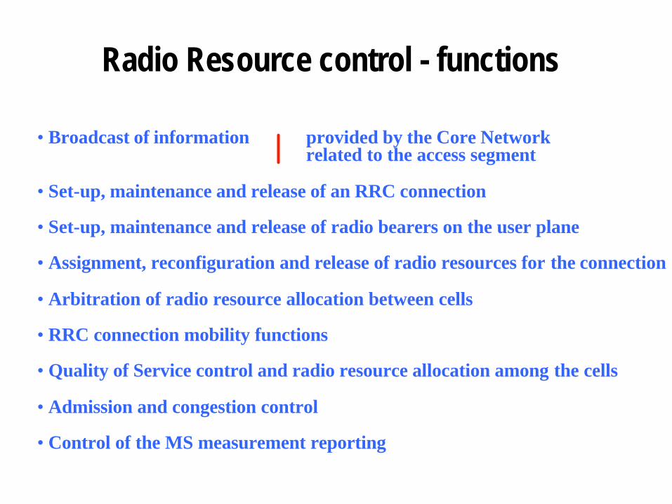
Radio Resource control - functions
•Broadcast of information provided by the Core Networkrelated to the access segment
•Set-up, maintenance and release of an RRC connection
•Set-up, maintenance and release of radio bearers on the user plane
•Assignment, reconfiguration and release of radio resources for the connection
•Arbitration of radio resource allocation between cells
•RRC connection mobility functions
•Quality of Service control and radio resource allocation among the cells
•Admission and congestion control
•Control of the MS measurement reporting

Orthogonal Variable Spreading Factor
c4,1= (1,1,1,1)
c2,1 = (1,1)
c4,2 = (1,1,-1,-1)
c4,3 = (1,-1,1,-1)c2,2 = (1,-1)
c4,4 = (1,-1,-1,1)

Uplink Variable Rate
1-rate
10 ms
Variablerate
1/2-rate
1/4-rate
0-rate
: DPCCH (Pilot+TPC+RI)
: DPDCH (Data)
R = 1 R = 1/2 R = 0 R = 0 R = 1/2

Downlink Variable Rate (DTX based)
1-rate
1/2-rate
1/4-rate
0-rate
0.625 ms
: DPCCH-part (Pilot+TPC+RI)
: DPDCH-part (Data)

TD-CDMA (Time Division Duplex)
Multiple access scheme TDMA/CDMA
Channel spacing 5 MHz
Charrier chip rate 3.84 Mchips/s
Spreading factor 1-16
Frame length 10 ms
Multirate concept multislot /multicode
Modulation QPSK
Burst Types burst 1 long delay spreadburst 2 short delay spread
Detection Coherent, based on midamble

TDD - frame structuremultiframe =24 frames (240 ms)
frame = 15 TS (10 ms)
DLUL
UL>DL
codes
0 23
BCCH RACH DL TCH UL TCH
0 15
switching points DL>UL

Packet Data Service
In W-CDMA, data packets can be transmitted in 3 ways:• (a) RACH (Random Access Channel): used for small
amount of data; no reservations, thus low latency; but, collisions and no power control (on RACH)
• (b) Request a dedicated channel (like VC setup): MS sends a Res Req msg (on RACH) with traffic specs; network returns a Req All + Cap All (with transport formats) on FACH, if resources are available; Cap_All may be issued separately (later) if the network load is high; MS transmits after receiving the Cap All.

Packet Data Service (cont)
• (c) use existing dedicated channel (before it expires): if a DCH was recently used, go ahead and tx the unscheduled pkt on that channel. If timer expired, the MS can still omit the Res Req and issue just the Cap All


Real time services
• MS issues Res_Req on RACH (or on DCH if it has one going)
• Network issues Res All (with TF parameters)• MS starts transmission immediately (no wait for Cap_All)• Network may later reduce/restore the TF depending on
load fluctuations

Congestion Control
• Congestion may occur even after careful admission control• without cong. control, mobiles tend to increase their tx
power, to combat interference, thus aggravating the problem
• solutions:(a) lower bit rate of users insensitive to delay;(b) perform interfrequency handovers( c) remove connection(s)
• congestion control remedies activated by load thresholds

Handover Functions
basic featurefor the RANarchitecture
hard
seamless
soft
Handover modes

Cell A Cell B
Cell C
Signal
margin
Soft handoverregion
ADD threshold
DROP threshold
Time margin
Ec/No
Time
Macrodiversity - active set

The macrodiversity control
controlpoint two control
points
control points mobility
mobility