Embed Size (px)
Citation preview

1
REVIEW OF FLOW CONTROL MECHANISMS OF
LEADING-EDGE VORTICES
I. Gursul, Z. Wang and E. Vardaki
Department of Mechanical Engineering
University of Bath
Bath BA2 7AY
United Kingdom
Vortex control concepts employed for slender and nonslender delta wings were
reviewed. Important aspects of flow control include flow separation, vortex formation, flow
reattachment, vortex breakdown, and vortex instabilities. The occurrence and relative
importance of these phenomena strongly depend on the wing sweep angle. Various flow
control methods were discussed: multiple vortices, control surfaces, blowing and suction,
low-frequency and high-frequency excitation, feedback control, passive control with wing
flexibility, and plasma actuators. For slender delta wings, control of vortex breakdown is
achieved by modifications to swirl level and external pressure gradient acting on the vortex
core. Effects of flow control methods on these two parameters were discussed, and their
effectiveness was compared whenever possible. With the high-frequency excitation of the
separated shear layer, reattachment and lift enhancement in the post-stall region is observed,
which is orders of magnitude more effective than steady blowing. This effect is more
pronounced for nonslender wings. Re-formation of vortices is possible with sufficient
amplitude of forcing at the optimum frequency. Passive lift enhancement on flexible wings is
due to the self-excited wing vibrations, which occur when the frequency of wing vibrations is
close to the frequency of the shear layer instabilities, and promote flow reattachment.

2
Contents
1. Introduction
1.1. Flow Physics of Slender Delta Wings
1.2. Flow Physics of Nonslender Delta Wings
1.3. Overview of Unsteady Flow Phenomena
2. Multiple Vortices
3. Control Surfaces
4. Blowing and Suction
4.1. Leading-Edge Blowing and Suction
4.2. Small Aspect Ratio Jets
4.3. Trailing-Edge Jets
5. Unsteady Excitation
5.1. Low-Frequency Excitation
5.2.High-Frequency Excitation
6. Closed-Loop Control
7. Passive Control with Wing Flexibility
8. Other Methods
9. Conclusions
Acknowledgements
References

3
Nomenclature
AR = amplitude ratio
CL = lift coefficient
CN = normal force coefficient
Cµ = momentum coefficient
c = chord length
Eu = spectral density of velocity fluctuations
f = frequency
fc/U∞ = dimensionless frequency
s = semi-span
St = Strouhal number, fc/U∞
U∞ = free-stream velocity
u = axial or chordwise velocity
x = chordwise distance
xbd = location of breakdown from apex
y = spanwise distance
z = distance normal to the wing surface
α = angle of attack
αR = angle of attack at which reattachment reaches centreline
Λ = leading-edge sweep angle
∆CN = change in normal force coefficient
∆φ = amplitude of roll oscillations
∆xbd = change in breakdown location
Γ = circulation
δ = flap angle; wing-tip displacement
Φ = swirl angle
ω = vorticity
1. Introduction
Controlling vortical flows over delta wings may have various benefits, such as
enhancement of lift force, generation of forces and moments for flight control, and
attenuation of wing and fin buffeting. These objectives require modifications to the vortex

4
location, strength and structure, and can be met with active and passive flow control methods.
In most cases, passive flow control techniques may cause undesired effects in different flow
regimes. For example, they may cause premature vortex breakdown at moderate incidences,
whereas they may increase the vortex lift at low angles of attack due to the increased strength
of the vortex. On the other hand, active flow control methods can achieve multiple tasks
during different flight regimes.
Control methods include manipulation of one or more of the following flow
phenomena: flow separation from the wing, separated shear layer, vortex formation, flow
reattachment on the wing surface, and vortex breakdown. These flow phenomena are usually
coupled to each other. The occurrence and relative importance of these phenomena strongly
depend on the wing sweep angle. In particular, flow reattachment and vortex breakdown are
two important phenomena which determine the effective flow control strategies. Before
discussing the flow control methods, flow physics for slender and nonslender delta wings as
well as unsteady flow phenomena will be briefly summarised.
1.1 Flow Physics of Slender Delta Wings
The flow over a delta wing is characterised by a pair of counter-rotating leading-edge
vortices that are formed by the roll-up of vortex sheets as shown in Figure 1. The flow
separates from the leading edge of the wing to form a curved free shear layer above the
suction side of the wing, which rolls up into a core. The time-averaged axial velocity is jet-
like at low and moderate incidences. The large axial velocities in the vortex core are due to
very low pressures, which also generate additional suction and lift force, known as vortex lift,
on the delta wings. Vortex lift contribution increases with wing sweep angle [1].
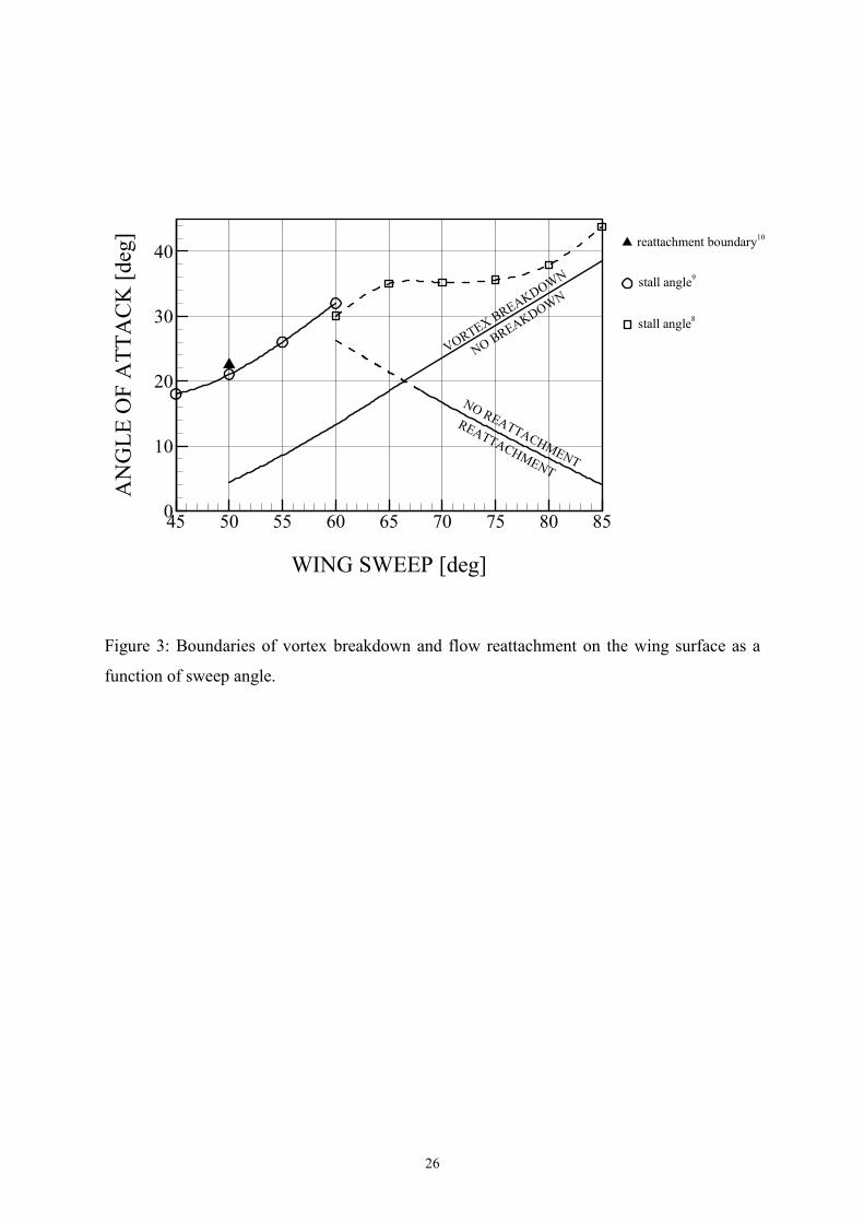
For small angles of attack, the primary reattachment line is inboard of the leading-
edge vortex as shown schematically in a cross-flow plane in Figure 2(a). The reattachment
location on the wing surface (point A) moves inboard with increasing angle of attack, and
reaches the wing centreline at a particular incidence. Beyond this limiting angle of attack αR,
flow reattachment to the wing surface is not possible and point A moves to the wing
centreline and away from the wing surface as shown in Figure 2(b). The prediction of αR
with wing sweep angle [2] is shown in Figure 3. This prediction is only valid for slender
wings (defined as wing sweep angle Λ ≥ 65° in this paper). For slender wings, it is seen that
the reattachment incidence decreases with increasing wing sweep angle. Therefore, on highly
swept wings, reattachment does not occur beyond very small angles of attack. The typical
5
flow pattern is similar to that shown in Figure 2(b), which suggests that reattachment is
difficult to manipulate.
At a sufficiently high angle of attack, the vortices undergo a sudden expansion (as
sketched in Figure 4), known as vortex breakdown. The axial flow downstream becomes
wake-like with very low velocities. For slender wings, vortex breakdown is the dominant
flow mechanism that is responsible for decreased lift. It is also the dominant source of
unsteadiness that causes wing and fin buffeting [3]. The dynamic response of leading edge
vortices and breakdown is important for the flight of modern fighter aircraft. Hence, control
of vortex breakdown has been the subject of many investigations [4].
Experiments and theoretical explanations of the vortex breakdown phenomenon [3]
agree that there are two important parameters affecting the occurrence and movement of
vortex breakdown: swirl level and pressure gradient. An increase in the magnitude of either
parameter promotes the earlier occurrence of breakdown. Very early experiments
demonstrated that vortex breakdown moves upstream over delta wings when the magnitude
of either parameter is increased [5]. More recently, it was shown that the minimum swirl
level required for breakdown decreases with increasing magnitude of adverse pressure
gradient [6]. Naturally, flow control methods for the delay of vortex breakdown rely on
modification of these two parameters. These will be discussed in more detail later on in the
paper.
Vortex breakdown appears on the wing with increasing angle of attack and crosses the
trailing-edge at a particular incidence αBD. The variation of this angle of attack with wing
sweep angle [7] is also shown in Figure 3. It is seen that this angle of attack increases with
increasing wing sweep angle. In addition, the stall angle from Reference 8 is shown in the
same figure. It is seen that, as the relative contribution of vortex lift increases with sweep
angle, the occurrence of breakdown on the wing surface accelerates the stall.
1.2 Flow Physics of Nonslender Delta Wings
Vortical flow over nonslender delta wings (Λ ≤ 55°) has recently become a topic of
increased interest in the literature. While the flow topology over more slender wings,
typically Λ ≥ 65°, has been extensively studied and is now reasonably well understood, the
flow over lower sweep wings has only recently attracted more attention [9]. Vortical flows
develop at very low angles of attack, and form much closer to the wing surface. One of the
distinct features of nonslender wings is that reattachment of the separated flow is possible

6
even after breakdown reaches the apex of the wing. However, at large angles of attack in the
post-stall region, reattachment is not possible, and completely stalled flow occurs on the
wing. Active and passive control of reattachment may be beneficial for lift enhancement in
the post-stall region.
According to Polhamus’ leading-edge suction analogy [1], the vortex lift contribution
becomes a smaller portion of the total lift as the sweep angle decreases. Vortex breakdown
occurs over the wing even at small incidences, and there is no obvious correlation between
the onset of vortex breakdown over nonslender wings and the change of the lift coefficient.
Hence, vortex breakdown is not a limiting phenomenon as far as the lift force is concerned
for nonslender wings. On the contrary, flow reattachment is key to any flow control strategy
as suggested in Figure 3. As theoretical and computational predictions of αR are not
available for nonslender delta wings, variation of αR has been estimated from the
experiments. In this figure, the only direct experimental observation [10] (by flow
visualization of the reattachment line) as well as stall angles from References 8 and 9 are
shown for nonslender wings. The stall angle should be slightly larger than αR, hence can be
used as a reasonable estimate of αR. It is concluded from Figure 3 that the typical flow
pattern is similar to that shown in Figure 2(a), which suggests that reattachment can be
manipulated. These differences between the slender and nonslender wings determine which
flow control methods are effective.
1.3 Overview of Unsteady Flow Phenomena
Active flow control methods generally rely on unsteady excitation in flow control
applications. Unsteady forcing has been used for the control of vortices and breakdown in
some cases. Hence it is useful to review unsteady aspects of vortical flow over delta wings.
Most of the knowledge of unsteady flow phenomena is on slender delta wings. There are
various sources of unsteadiness [3]: shear layer instabilities (as sketched in Figure 4), vortex
wandering, helical mode instability of vortex breakdown (also sketched in Figure 4),
oscillations of breakdown, vortex interaction, and vortex shedding. The main instability
associated with vortex breakdown is the helical mode instability. The spiral form of
breakdown is a consequence of this instability of the breakdown wake. The spectrum of
unsteady flow phenomena which have quasi-periodic nature is shown in Figure 5. The
frequency spectrum of the unsteady flow phenomena that exist over stationary wings is very
wide, which is one of the challenges in numerical simulations of these flows. Vortex

7
breakdown, vortex interactions, and vortex shedding, either alone or in combination, play an
important role in wing and fin buffeting, although vortex breakdown is the main source of
buffeting over slender wings.
In addition to these phenomena over stationary wings, frequency response of vortex
breakdown to external excitation is important with regard to flow control applications. When
vortex breakdown is subjected to external harmonic forcing (such as wing oscillations, free
stream unsteadiness, oscillating control surfaces, oscillating fins and bodies downstream), its
response has been found to be similar to a first order dynamic system, with a time constant
τU∞/c order of unity [3]. Figure 6 shows the variation of the amplitude ratio, which is
defined as the ratio of the rms value of the fluctuations of breakdown location to its quasi-
steady counterpart, as a function of dimensionless frequency for different oscillating fin
locations [11] as well as for pitching wings [12]. It is seen that the amplitude attenuation is
similar to that of a low-pass filter. This suggests that, for frequencies higher than a cutoff
frequency, disturbances are not propagated upstream and vortex breakdown does not respond
to the external forcing. The importance of this feature with respect to flow control with
unsteady forcing will be discussed later on in the paper.
2. Multiple Vortices
Multiple vortices exist over many aircraft configurations. These vortices originating
from forebodies, strakes and canards interact with the vortical flow on the main wing. It has
been found that these upstream vortices persist over the wing and energize the flow, delaying
the stall on the main wing. A generic example is double delta wings [13] as shown in Figure
7. In this case a 76°/40° double delta wing is shown to exhibit coherent leading-edge vortices
(and breakdown) on the main wing even beyond α = 20°. In the absence of strake vortices, a
40° sweep delta wing would stall [9] around 17°.
Similar favourable interactions take place for canard-wing configurations. It was
shown that the interaction process delays the breakdown of the wing vortex [14]. Myose et al
[15] showed that the most favourable effect in terms of breakdown delay was achieved when
the canard was located closest to the main wing (see Figure 8), and a 19% delay in stall angle
was reported. It appears that optimum alignment of canard vortices could provide substantial
delays in stall, due to the enhancement of pressure gradient on the wing surface.
The above examples demonstrate the favourable effect of vortices originated from
upstream. There are also flow control examples, which are due to the vortices developed

8
downstream. Landahl and Widnall [16] pointed out that, by carefully positioning the canard
above the main wing, delay of vortex breakdown on the canard was possible. The stall angle
was delayed to 50°. Another example is a tandem delta wing arrangement known as a
chinard configuration [17] shown in Figure 9. Note that the dye is released near the apex of
the foreplane. This 65°/65° planform exhibits a significant delay in the development of
vortex breakdown compared to a simple delta wing of similar sweep due to a favourable
interaction between the foreplane and main wing vortices.
3. Control Surfaces
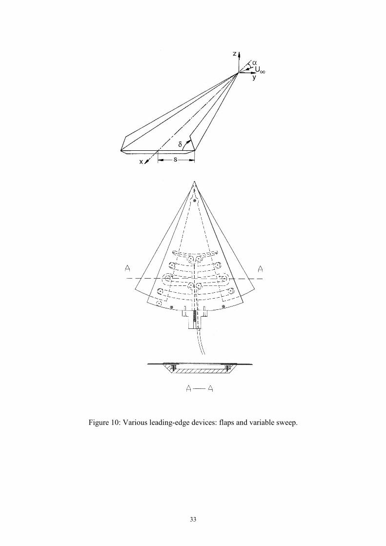
Various control surfaces [4] have been investigated to control the formation, location,
strength, and breakdown of leading-edge vortices. These are usually leading-edge devices as
shown in Figure 10. Since all of the vorticity of leading-edge vortices originates from the
separation point along the leading-edge, leading-edge flaps are particularly attractive tools
that can be used to influence the strength and structure of these vortices. Leading-edge flaps
that are deflected downward have been found to reduce drag and improve the lift-to-drag
ratio [18]. On the other hand, the flap deflection in the upward direction causes an increase
in lift as well as drag. This type of vortex management can be used for landing or
aerodynamic maneuvers [18]. It has been found that the flaps deflected upward generate a
stronger vortex lift at low and moderate angles of attack [19]. However, flaps may also
induce vortex breakdown [20] as shown in Figure 11. Leading-edge flaps modify the
strength and location of the vortices, thereby affecting the parameters that control vortex
breakdown. It was shown [20] that breakdown location and its sensitivity strongly depend on
incidence and flap angle. It is seen from Figure 11 that the variation of breakdown location is
monotonic for α ≤ 30°. For the larger angle of attack, the variation is not monotonic, and
therefore, not suitable for feedback control purposes. As a variation of the leading-edge flap
concept, mini and micro flaps have been used to manipulate flow separation from a rounded
leading-edge and hence control the vortices and aerodynamic forces [21].
A variable leading-edge extension [22] (see Figure 10) that effectively varies the
sweep angle has been used to control leading-edge vortices and breakdown. The advantage
of this method is that the variation of breakdown with sweep angle is monotonic, hence
suitable for feedback control purposes. Because most of the vorticity within the vortex core
originates from a small region near the apex of the wing, an apex flap can be an effective

9
control surface [23]. It was shown that a drooping apex flap [24] could delay vortex
breakdown.
4. Blowing and Suction
Blowing and suction applied at various locations are commonly used as flow control
methods for leading-edge vortices and breakdown. The most widely used versions include:
(a) leading-edge suction/blowing, (b) blowing from small aspect ratio jets (usually along the
core or parallel to leading-edge), and (c) trailing-edge blowing. These are discussed in detail
below.
4.1. Leading-Edge Blowing and Suction
Since the vorticity of the leading-edge vortices originates from the separation line
along the leading-edge, control of separation characteristics or shear layer can be used to
influence the strength and location of the vortices as well as the location of vortex
breakdown. Blowing in outward direction [25, 26] (see Figure 12(a)), upward direction [27],
upward direction with a Coanda surface [28-30] (see Figure 12(b)), and suction [30, 31] at the
leading-edge have been employed, but these methods substantially differ in terms of their
effect on the swirl level in the vortex. For the blowing in outward direction, the main
features of the flow are similar to an inclined jet in cross-flow [32], where strong jet vortices
are formed and may merge with the leading-edge vortex [25]. There are strong similarities to
the tip blowing on a high-aspect ratio wing [33], where complex interaction of jet and wing
vortices leads to a variety of possible flow patterns. In general, the total circulation increases
with blowing. Similarly, for a 60° sweep delta wing [25], the strength of the leading-edge
vortex increases with the jet momentum flux. This increased strength of vortex provides lift
enhancement at low incidences, but causes premature vortex breakdown at moderate
incidences, which results in loss of lift [26]. Vortices are displaced outboard and away from
the wing surface, which provides rolling moment for asymmetrical blowing.
The effect of blowing is more complicated when the Coanda effect is utilized [28, 29].
At low incidences, completely attached flow may be achieved, eliminating the leading-edge
vortex. Although it is not clear what effect blowing has on the strength of vortices at
moderate incidences, significant rolling moment can be generated, which results from a
combination of factors such as vortex strength, distance from the wing surface and its
spanwise location, and vortex breakdown location. The effect of blowing on the normal force

10
coefficient appears to be small at low to moderate incidences (see Figure 13), even though
significant rolling moment can be generated with asymmetric blowing [28]. More interesting
observation is the lift enhancement in the post-stall region. For the typical values of Cµ used,
an effectiveness parameter of ∆CN/Cµ = 4 to 5 was found for α = 40° and 45°. This lift
enhancement in the post-stall region is due to the flow reattachment as the blowing energizes
the separated shear layer.
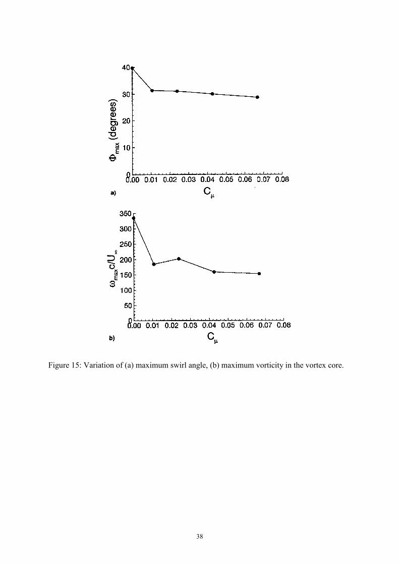
Suction reduces the strength and swirl level due to the removal of some of the vorticity
shed from the leading-edge. Figure 14(a) shows how the location of shear layer and vortex is
modified upstream of breakdown when suction is applied [31]. Figure 14(b) shows the axial
velocity contours at the trailing-edge, which show the change from wake-like to jet-like
velocity as a result of the delay of vortex breakdown. Detailed measurements [31] show that
maximum swirl angle and vorticity in the core decrease with suction (see Figure 15), which
causes the vortex breakdown location to move downstream. There is also some reduction in
circulation. It is worth noting that the leading-edge suction technique does not require thick
rounded leading edges. Control of vortices can be achieved without the use of the Coanda jet
effect.
4.2 Small Aspect Ratio Jets
Small aspect ratio jets have been used for adding momentum from a location near the
apex in the symmetry plane and parallel to the leading-edge [34, 35] (see Figure 16), for
along-the-core blowing underneath the vortex axis [36, 37], for spanwise blowing underneath
the vortex axis [38], and outward blowing from the leading-edge [39].
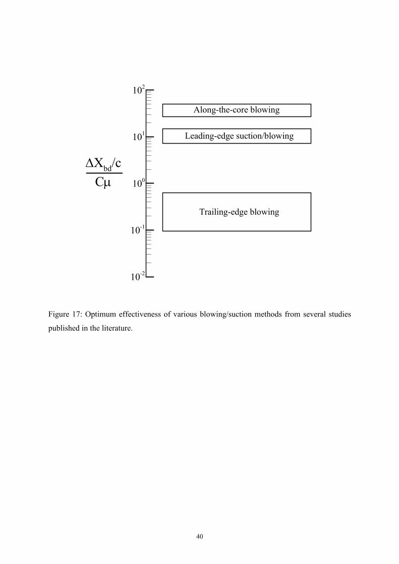
Along-the-core blowing [36, 37] accelerates the axial flow in the core, and modifies
the pressure gradient favourably. Figure 17 shows the effectiveness of various
blowing/suction methods from various studies published in the literature [30, 31, 36, 37, 40-
47]. Here the effectiveness is defined as (∆xbd/c)/Cµ, where ∆xbd is the change in breakdown
location (positive corresponding to delay), c is the chord length and Cµ is the momentum
coefficient. Figure 17 shows that along-the-core blowing is the most effective method in
terms of delaying vortex breakdown. This can be attributed to the importance of the pressure
gradient affecting the vortex core. It is also seen that the effectiveness of blowing and
suction from the leading-edge is nearly the same. The effectiveness of trailing-edge blowing
is the lowest among all blowing methods considered.

11
Blowing parallel to the leading-edge from a location near the apex and in the
symmetry plane [34] showed substantial lift enhancement in the post-stall region, in
particular for a low sweep angle of Λ = 40°. At an incidence of α = 30°, an effectiveness of
∆CL/Cµ around 5 was found for Cµ = 0.09. Campbell [35] reported ∆CL/Cµ near 7 for Cµ =
0.04 for a 45° sweep delta wing-forebody configuration. Hence it is clear that there are
potential benefits of this type of blowing for nonslender wings for delaying stall and
enhancing lift.
Blowing from a low-aspect ratio slot at the leading-edge [39] produces a separate vortex
with the same sign as shown in Figure 18. The jet-induced vortices in this case may not
merge with the leading-edge vortex, unlike the blowing from nearly 2-D slots (see Figure 12)
where merged vortices are observed even for large values of Cµ up to Cµ ≈ 0.1.
4.3 Trailing-Edge Jets
The effect of trailing-edge jets on wing vortices and vortex breakdown has been
investigated in several studies [41-47]. Blowing at the trailing-edge also modifies the
external pressure gradient and causes delay of vortex breakdown. Favourable effect of a
trailing-edge jet (see Figure 19(a)) could be observed even in the presence of a fin, which
produces a strong adverse pressure gradient for a leading-edge vortex. Figure 19(b) shows
that fin-induced vortex breakdown can be delayed even for the head-on collision of the
leading-edge vortex with the fin [45]. Hence the adverse pressure gradient caused by the
presence of the fin could be overcome with a trailing-edge jet.
The effectiveness of a trailing-edge jet depends on the wing sweep angle [46, 47]. It
appears that it becomes more difficult to delay vortex breakdown with decreasing sweep
angle. For nonslender wings, vortex breakdown occurs over the wing even at low incidences.
This is likely to be due to the fact that the external pressure gradient is more adverse for
nonslender wings than for slender wings. As a result, the effectiveness of breakdown control
methods is much less. Figure 20 shows the optimum effectiveness values (collected from
various studies in References 41-47) as a function of wing sweep angle when trailing-edge
jets are used. Decreasing effectiveness for nonslender wings might be important for wing/fin
buffeting considerations.
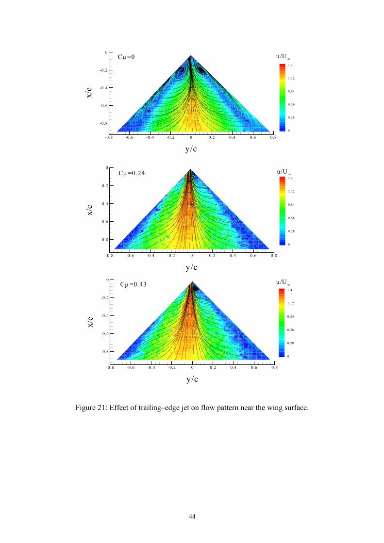
Even though the delay of breakdown is more difficult for nonslender wings, the effect of
trailing-edge jets is substantial near the stall angle. Figure 21 shows velocity and streamlines
near the wing surface for a Λ = 50° wing at α = 20° [47]. It is seen that near-stall flow

12
pattern (with reattachment near the symmetry plane) changes with blowing and two separate
reattachment lines are identified. Wind tunnel experiments show that largest changes in the
lift force occur near the stall angle [46, 47].
5. Unsteady Excitation
There have been various attempts to control vortices and breakdown by using
unsteady excitation. These include small amplitude wing oscillations, small and large
amplitude oscillations of leading-edge flaps, periodic variations of sweep angle, periodic
suction or blowing, and combined use of leading-edge flaps and intermittent trailing-edge
blowing, which are summarized in Reference 3. These studies fall into two categories: (i)
low-frequency excitation, St = O(0.1), and (ii) high-frequency excitation, St = O(1).
5.1 Low-Frequency Excitation
For the low-frequency excitation, there have been reports of increased vortex
circulation [19, 48] and delay of vortex breakdown [48] for oscillating flaps, delay of vortex
breakdown for harmonic variations of sweep angle for a variable sweep wing [22], and delay
of breakdown for combined flaps and unsteady trailing-edge blowing [49]. In these
experimental studies, the frequency range was in fc/U∞ = 0.13 to 0.17. It is seen from Figure
5 that, for the low-frequency excitation, it is not clear which unsteady phenomena are
exploited. However, it is suggested [22] that the variations in the external pressure gradient
generated by unsteady excitation play a major role.
5.2 High-Frequency Excitation
For the high-frequency excitation, the effects of forcing will be considered separately
for slender and nonslender wings. As discussed previously, flow reattachment does not
generally occur for slender wings. Gad-el-Hak and Blackwelder [50] applied periodic
perturbations of injection and suction along the leading-edge of a delta wing (Λ = 60°). They
found maximum changes in the evolution of the shear layer when the frequency of
perturbations (St = 5.5) was the subharmonic of the frequency of Kelvin-Helmholtz
instability (see Figure 5). However, no results were reported regarding the structure of the
main vortex and the effect on vortex breakdown. Gu et al [30] applied periodic suction-
blowing in the tangential direction along the leading-edge of the wing (Λ = 75°) and reported
a delay of vortex breakdown. The most effective period of the alternate suction-blowing

13
corresponded to fc/U∞ = 1.3. In general, the effect of unsteady excitation on vortex
breakdown is small for slender wings. The physical explanation of this observation is related
to the wave propagation characteristics of leading-edge vortices as discussed in Section 1.3
(see Figure 6). For high-frequency excitation (St = O(1)), vortex breakdown does not
respond to the external forcing.
For a less slender wing (Λ = 60°, which is a transitional case between the slender and
nonslender wings), it was shown that oscillatory blowing at the leading edge can enhance the
lift at high angles of attack [51] as shown in Figure 22, and optimum reduced frequency
varied in the range of fc/U∞ = 1 to 2. Again, the lift enhancement is in the post-stall region,
and is due to the flow reattachment with unsteady excitation. This is not related to the vortex
breakdown phenomenon. In fact, for pre-stall incidences when vortex breakdown exists over
the wing, the effect of the excitation on the normal force is negligible as shown in Figure 22.
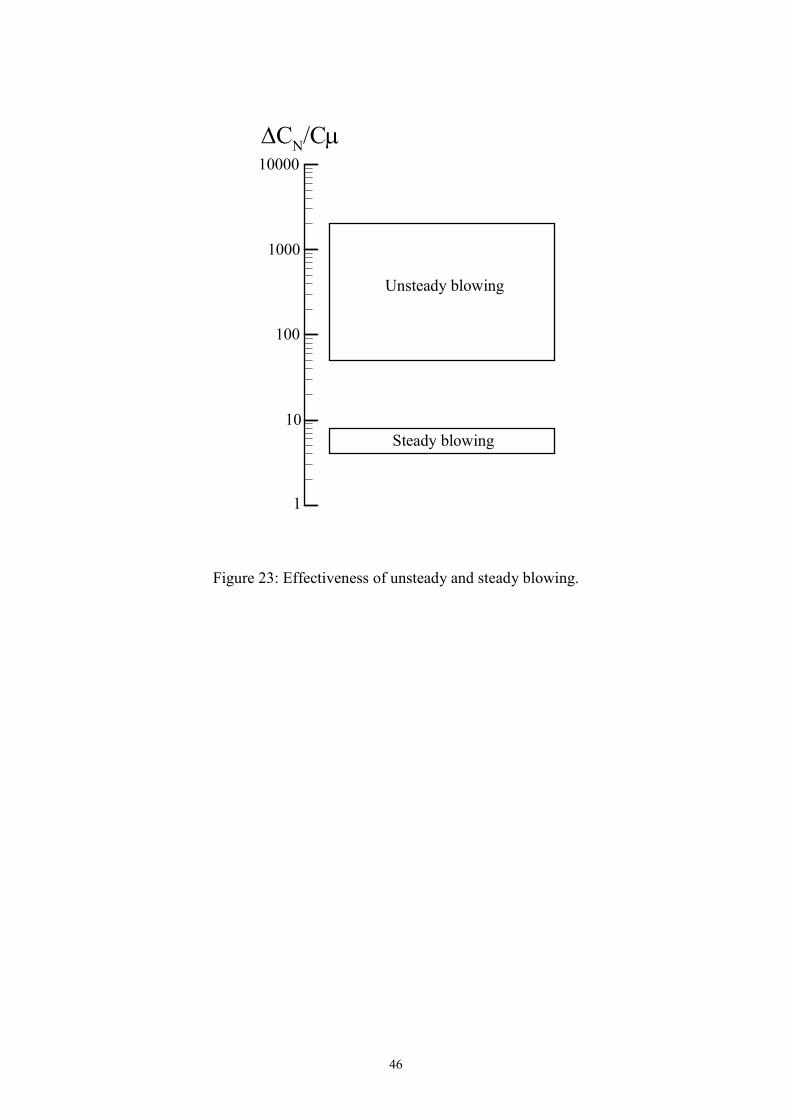
Figure 23 compares the effectiveness ∆CN/Cµ for the unsteady blowing [51, 52] and steady
blowing [28, 34, 35]. It is seen that there is great potential in active flow control based on
unsteady excitation in the post-stall lift enhancement. In a study on the effect of small
amplitude flap oscillations, the strength of the vortices was found to be larger than that of the
quasi-steady case [53], when the excitation frequency was St = 1.2. This range of effective
frequencies presumably corresponds to subharmonics of the Kelvin-Helmholtz instability due
to vortex pairing (see Figure 5). In some of these applications, it is not known whether the
complete reattachment occurs. Nevertheless there is still evidence of performance
improvement by manipulating the development of the separated shear layer.
For nonslender delta wings, there is even greater potential with unsteady excitation
[52], since the flow reattachment is likely to occur on the wing surface (see Figures 2 and 3).
Rigid delta wings undergoing small amplitude oscillations [54] exhibit reattachment in the
post-stall region. Figure 24 shows flow visualization for the stationary and oscillating delta
wing (with an amplitude of 1° and St = 1.0) for a Λ = 50° wing. While the difference is small
for α = 15°, change in the size of the separation region is considerable at higher incidences.
(The dashed lines indicate the wing centreline). Figure 25 shows the time-averaged flow
visualization for the three incidences under the same conditions as those in Figure 24. It is
seen that the most dramatic result is observed for the post-stall condition at α = 25°.
However, even in the pre-stall region, earlier reattachment with unsteady forcing is obvious.
The dramatic change for α = 25° is best illustrated in Figure 26. The time-averaged

14
streamline pattern near the wing surface indicates the change from the stalled flow for the
stationary wing to the reattached flow with unsteady forcing.
Within the reattachment region, axial flow may develop, resulting in re-formation of
the leading-edge vortices. Figure 27 shows examples of vortex re-formation [54], which
occurs when the amplitude of forcing is sufficiently large and the frequency of excitation is
near an optimum value. For an oscillating wing, the leading-edge oscillations act as an
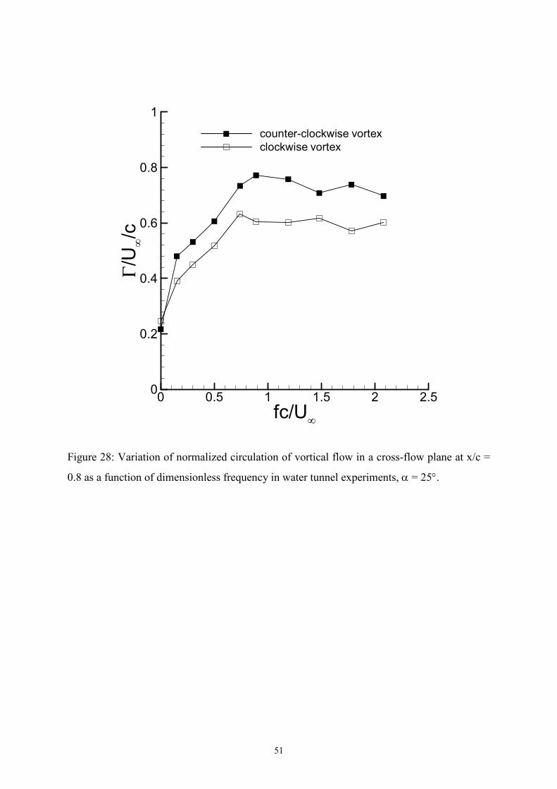
unsteady source of vorticity. In fact, the time-averaged vorticity flux is expected to increase
with the wing oscillations, as the vorticity flux is proportional to 2sU , where sU denotes the
velocity outside the boundary layer at the separation point. This is confirmed by the
increased circulation as shown in Figure 28. Although the leading edge vortices become
stronger due to the leading edge motion, vortex breakdown is delayed for the oscillating wing
compared to the stationary wing for which breakdown is at the apex. This appears to be in
contrast to the well-known studies of vortex breakdown, which indicate that increased
strength of vortices should cause premature, rather than delayed, breakdown. This result
suggests that streamwise pressure gradient is also modified favourably due to the wing
motion.
For simple delta wings and cropped delta wings [55] with Λ = 50°, 40°, and 30°, an
optimum frequency around St = 1 to 2 was identified based on the delay of vortex breakdown
or the size of the reattachment region. Figure 29 shows an example of the variation of
breakdown location as a function of Strouhal number at two amplitudes for a Λ = 50° wing.
It is seen that the mean breakdown location becomes a maximum at an optimum frequency.
It was confirmed [53] that this range of optimum frequencies correspond to dominant peaks
in the spectra of velocity fluctuations in highly three-dimensional shear layers over the wings
in the post-stall region.
An important parameter is the wing sweep angle. The effect of excitation on a swept
wing is similar to the response of the flow over a backward-facing step [56] to the periodic
excitation. However, for zero sweep angle, formation of a closed separation bubble at high
angles of attack in the post-stall region is not possible. It seems that moderate sweep angles
help the formation of semi-closed separation bubbles, hence the wing sweep is beneficial in
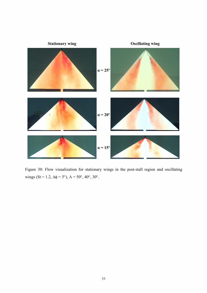
flow reattachment. Figure 30 shows the effect of unsteady excitation for Λ = 30°, 40°, and
50° delta wings in the post-stall region. It is seen that the reattachment process is generic for
nonslender wings. However, there is a lower limit of sweep angle below which the beneficial
effect of wing sweep will diminish. This lower limit of sweep angle is around Λ = 20° [55].

15
Symmetric perturbations in the form of small amplitude pitching oscillations (1°
amplitude) were also studied for Λ = 50° simple delta wing. The results show that symmetric
perturbations also promote reattachment and vortex re-formation [55]. Yaniktepe and
Rockwell [57] showed that, for even lower sweep angle of Λ = 38.7°, the effect of small
perturbations (1° amplitude) is substantial as shown in Figure 31 for α = 17°, which produces
stalled flow for the stationary wing. The most effective frequency of excitation, which
corresponds to fc/U∞ = 2.06, produces a flow pattern characteristic of a typical leading-edge
vortex. Hence, for active control purposes, both symmetric and anti-symmetric excitations
are effective.
6. Closed-Loop Control
The pressure fluctuations induced by the helical mode instability of vortex breakdown
can be measured and used as a feedback signal for active control. In such an approach, the
rms value of pressure was chosen as the control variable and a feedback control strategy was
considered [58] as shown in Figure 32. The monotonic variation of the amplitude of the
pressure fluctuations with vortex breakdown location makes the feedback control possible.
In identifying a suitable flow controller, several methods were considered, including
blowing, suction, and flaps. However, the relationship between the vortex breakdown
location and control parameter is unknown or undesirable (i.e., not monotonic) for these
methods. A desirable controller should have a monotonic relationship between the control
parameter and breakdown location. It was shown [58] that it was feasible to use a variable
sweep angle mechanism (see Figure 32(a)) as a means of controlling the breakdown location
by influencing the circulation of the leading-edge vortex. The system was idealised as a first-
order system, and integral control was used. The feedback control of breakdown was
demonstrated for stationary as well as pitching delta wings. In a recent study, a closed-loop
controller was developed using along-core blowing [59].
7. Passive Control with Wing Flexibility
Passive lift enhancement for flexible delta wings has been demonstrated as a potential
method for the control of vortex-dominated wing flows [60]. Force measurements over a
range of nonslender delta wings (with sweep angles Λ = 40° to 55°) have demonstrated the
ability of a flexible wing to enhance lift and delay stall compared with a rigid wing of similar
geometry. An example for Λ = 40° is shown in Figure 33. This recently discovered

16
phenomenon appears to be a feature of nonslender wings. Flow visualization, PIV and LDV
measurements show that flow reattachment takes place on the flexible wings in the post-stall
region of the rigid wings.
The lift increase in the post-stall region is accompanied by large self-excited
vibrations of the wings as shown in Figure 34. Various measurements including wing-tip
accelerations, rms rolling moment, and hot-wire measurements confirm that the dominant
mode of vibrations occurs in the second antisymmetric structural mode in the lift
enhancement region as shown in the inset of Figure 34. The self-excited vibrations are not
observed for a half-wing model, hence passive flow control for a flexible wing occurs only in
the anti-symmetric mode. The dominant frequency of the vibrations of various nonslender
delta wings is St = O(1). These vibrations promote reattachment of the shear layer, which
results in the lift enhancement. Figure 35 shows the tuft visualization and time-averaged
streamline pattern from the PIV measurements near the wing surface. It is seen that a node of
attachment exists on the centerline at around x/c = 0.2 and reattachment lines are easily
identified. There are strong similarities with the rigid delta wings undergoing small
amplitude oscillations.
Spectra of velocity fluctuations [55] along the shear layer are shown in Figure 36. The
large sharp peak in each spectrum corresponds to the wing vibrations. There are also broad
dominant peaks in the spectra of velocity fluctuations in the range of St = 1 to 5 for the post-
stall incidences, and these correspond to the shear layer instabilities. The center frequency of
these peaks decreases with streamwise distance as the shear layer vortices shed conically.
There is also a decrease in the spanwise direction due to the vortex pairing process as shown
in Figure 36. Near the mid-span, the broad peak is around St ≈ 1 and coincident with the
frequency of the wing vibrations. In summary, there is, not a single frequency, but, a range
of frequencies detected in the three-dimensional shear layer. The frequency of the structural
vibrations is in the same range as these natural frequencies [55].
8. Other Methods
Panton [61] examined the effect of geometric modifications to the apex region using a
wire screen or contouring the planform with a slightly higher sweep angle. The idea was to
decrease the total pressure by adding friction or to alter the vorticity distribution in the vortex
core. The higher sweep used locally near the apex, which does not produce a distinct second
vortex, was found to delay vortex breakdown, while the addition of the wire screen caused
17
premature breakdown. In another study [62], it was claimed that a delta wing with wavy
leading-edge could suppress the vortex breakdown compared to a conventional wing with
straight leading-edge. Although some delay of breakdown is obvious, the authors’ claim for
suppression of vortex breakdown seems to contradict the apparent breakdown in their flow
visualisation pictures.
Visbal and Gaitonde [63] investigated the use of simulated plasma actuators over a slender
delta wing. When the actuator was placed near the apex (see the inset in Figure 37), it was
found to be more effective than when the actuator was placed at the leading-edge or trailing-
edge. Considering that the actuator produces a wall-jet, this result is in agreement with
Figure 17. It is seen in Figure 37 that, when the control is off, vortex breakdown, which is
characterized by the presence of reversed axial flow, occurs on the wing. When the control is
on, vortex breakdown is completely suppressed and jet-like flow in the vortex core is
retained. Both pulsed and steady actuation were found to be effective. Recently, for an
Unmanned Air Vehicle (UAV) wing with sweep angle of 47 degrees, the ability of the
plasma actuators to produce roll maneuvers was demonstrated [64].
Forebody slot blowing [65] was shown to delay vortex breakdown for a generic
configuration as shown in Figure 38. It was suggested that spanwise blowing on the forebody
produces a vortex that interacts favourably with the wing vortex and also produces a
downwash effect. The overall effect of the type of blowing is similar to that of canard wings,
although the momentum coefficients are generally large for an active flow control method.
9. Conclusions
Vortex control concepts employed for slender and nonslender delta wings were
reviewed. Depending on the application, the objective of flow control methods may be
enhancement of lift force, generation of forces and moments for flight control, and
attenuation of buffeting. Important aspects of flow control include flow separation, vortex
formation, flow reattachment, vortex breakdown, and vortex instabilities. The occurrence
and relative importance of these phenomena strongly depend on the wing sweep angle. For
example, on slender wings, reattachment does not generally occur. For slender delta wings,
control of vortex breakdown is the primary goal of flow control methods. Delay of vortex
breakdown is possible with the modifications to the swirl level and pressure gradient. For
nonslender delta wings, one of the distinct features is that reattachment of the separated flow
is possible and can be manipulated. As active flow control methods generally rely on
18
unsteady excitation, naturally occurring unsteady flow phenomena in vortical flows and time
scales of the vortex breakdown need to be considered.
Various flow control methods were reviewed: multiple vortices, control surfaces,
blowing and suction, low-frequency and high-frequency excitation, feedback control, passive
control with wing flexibility, and plasma actuators. Both upstream and downstream vortices
may be used, if properly aligned, to delay vortex breakdown and postpone the stall on the
main wing or on the canard/foreplane, by improving the external pressure gradient acting on
the vortices. The use of control surfaces such as leading-edge flaps makes it possible to
control the location, strength, and structure of the vortices. Blowing and suction at the
leading-edge, trailing-edge, or along the core have differences in terms of their effects on
swirl level and pressure gradient affecting the vortex core. While leading-edge blowing
generally increases the strength of the vortices and may even cause premature vortex
breakdown at moderate incidences, suction reduces the strength and delays the vortex
breakdown. Along-the-core blowing is the most effective method for delaying vortex
breakdown by improving the external pressure gradient. Although trailing-edge jets are the
least effective methods, especially for nonslender wings, their effect is substantial near the
stall angle.
Active flow control using low-frequency excitation appears to modify only the
external pressure gradient. High-frequency excitation has small effect on vortex breakdown,
but can excite the Kelvin-Helmholtz instability of the separated shear layer and promote
reattachment. Lift enhancement in the post-stall region is due to the flow reattachment with
unsteady excitation, and orders of magnitude more effective than steady blowing. There is
even greater potential for nonslender wings. Moderate sweep angles help the formation of
semi-closed separation bubbles, hence the wing sweep is beneficial. With sufficient
amplitude of forcing near the optimum frequencies, re-formation of vortices is possible in the
post-stall region. Passive lift enhancement on flexible wings is due to the self-excited wing
vibrations, which promote flow reattachment in the post-stall region. This phenomenon is
observed when the frequency of the wing vibrations (St = O(1)) is in the same range as the
frequencies of the natural shear layer instabilities. Also, other active flow control methods
such as feedback control and plasma actuators were discussed.

19
Acknowledgements
The authors acknowledge the financial support of the Air Force Office of Scientific
Research (AFOSR), Engineering and Physical Sciences Research Council (EPSRC) and the
Ministry of Defence in the UK.
References
1. Polhamus, E. C., ‘Predictions of vortex lift characteristics by a leading edge suction
analogy’, Journal of Aircraft, Vol. 8, No. 4, pp. 193-199, 1971.
2. Mangler, K.W. and Smith, J.H.B., “A Theory of the Flow Past a Slender Delta Wing
with Leading Edge Separation”, Proceedings of Royal Society, A, vol. 251, 1959, pp. 200-
217.
3. Gursul, I., “Review of Unsteady Vortex Flows over Slender Delta Wings”, Journal of
Aircraft, vol. 42, no. 2, March-April 2005, pp. 299-319.
4. Mitchell, A.M. and Delery, J., “Research into Vortex Breakdown Control”, Progress
in Aerospace Sciences”, vol. 37, 2001, pp. 385-418.
5. Lambourne, N.C. and Bryer, D.W., “The Bursting of Leading Edge Vortices: Some
Observation and Discussion of the Phenomenon”, Aeronautical Research Council, R&M
3282, 1962.
6. Delery, J., Horowitz, E., Leuchter, O., and Solignac, J.L., “Etudes Fondamentales Sur
Les Ecoulements Tourbillonnaires”, La Recherche Aerospatiale, no. 2, 1984, pp. 81-104.
7. Erickson, G.E., “Water-Tunnel Studies of Leading-Edge Vortices”, Journal of
Aircraft, vol. 19, No. 6, June 1982, pp. 442-448.
8. Wentz, W.H., and Kohlman, D.L., “Vortex Breakdown on Slender Sharp-Edged
Wings”, Journal of Aircraft, vol. 8, no. 3, 1971, pp. 156-161.
9. Gursul, I., Gordnier, R., and Visbal, M., “Unsteady Aerodynamics of Nonslender
Delta Wings”, Progress in Aerospace Sciences, vol. 41, 2005, pp. 515-557.
10. Taylor, G. and Gursul, I., “Buffeting Flows over a Low Sweep Delta Wing”, AIAA
Journal, vol. 42, no. 9, September 2004, pp. 1737-1745.
11. Gursul, I. and Xie, W., “Interaction of Vortex Breakdown with an Oscillating Fin”,
AIAA Journal, vol. 39, no. 3, March 2001, pp. 438-446.
12. Greenwell, D.I., and Wood, N.J., “Some Observations on the Dynamic Response to
Wing Motion of the Vortex Burst Phenomenon”, Aeronautical Journal, vol. 98, no. 972, Feb.
1994, pp. 49-59.

20
13. Verhaagen, N.G., Jenkins, L.N., Kern, S.B., and Washburn, A.E., “A Study of the
Vortex Flow over a 76/40-deg Double-Delta Wing”, AIAA 95-0650, 33rd Aerospace
Sciences Meeting and Exhibit, January 9-12, 1995, Reno, NV.
14. Hummel, D. and Oelker, H.C., “Vortex Interference Effects on Close-Coupled Canard
Configuration at Low Speed”, Aerodynamics of Combat Aircraft Controls and of Ground
Effects, CP-465, AGARD, 1989, pp. 7-1 to 7-18.
15. Myose, R.Y., Hayashibara, S., Yeong, P.C. and Miller, L.S., “Effects of Canards on
Delta Wing Vortex Breakdown During Dynamic Pitching”, Journal of Aircraft, vol. 34, no. 2,
March-April 1997, pp. 168-173.
16. Landahl, M.Y. and Widnall, S.E., “Vortex Control”, Aircraft Wake Turbulence and
its Detection, Edited by J.H. Olsen, A. Goldburg, M. Rogers, Plenum Press, New York-
London, 1971, pp. 137-155.
17. Lynn, R. and Gursul, I., “Vortex Dynamics on a Generic UCAV Configuration”,
AIAA-2006-0061, 44th AIAA Aerospace Sciences Meeting and Exhibit, 9-12 January 2006,
Reno, NV.
18. Lamar, J.E. and Campbell, J.F., “Vortex Flaps – Advanced Control Devices for
Supercruise Fighters”, Aerospace America, January 1984, pp. 95-99.
19. Spedding, G.R., Maxworthy, T., and Rignot, E., “Unsteady Vortex Flows over Delta
Wings”, Proceedings of the 2nd AFOSR Workshop on Unsteady and Separated Flows, U.S.
Air Force Academy, Colorado Springs, CO, 1987, pp. 283-287.
20. Deng, Q. and Gursul, I., “Effect of Leading-Edge Flaps on Vortices and Vortex
Breakdown”, Journal of Aircraft, vol. 33, no. 6, November-December 1996, pp. 1079-1086.
21. Lee, G.W., Shih, C., Tai, Y.C., Tsao, T., Liu, C., Huang, A. and Ho, C.M., “robust
Vortex Control of a Delta Wing by Distributed Microelectromechanical-Systems Actuators”,
Journal of Aircraft, vol. 37, no. 4, July-August 2000, pp. 697-706.
22. Yang, H. and Gursul, I., “Vortex Breakdown over Unsteady Delta Wings and its
Control”, AIAA Journal, vol. 35, no. 3, 1997, pp. 571-574.
23. Rao, D.M. and Campbell, J.F., “Vortical Flow Management Techniques”, Progress in
Aerospace Sciences, vol. 24, 1987, pp. 173-224.
24. Klute, S.M., Rediniotis, O.K., and Telionis, D.P., “Flow Control over a Maneuvering
Delta Wing at High Angle of Attack”, AIAA Journal, vol. 34, no. 4, 1996, pp. 662-668.
25. Celik, Z.Z. and Roberts, L., “Vortical Flow Control on a Delta Wings by Lateral
Blowing”, AIAA 94-0509, 32nd Aerospace Sciences Meeting and Exhibit, January 10-13,
1994, Reno, NV.

21
26. Hong, J.S., Celik, Z.Z. and Roberts, L., “Effects of Leading-Edge Lateral Blowing on
Delta Wing Aerodynamics”, AIAA Journal, vol. 34, no. 12, December 1996, pp. 2471-2478.
27. Findlay, D., Kern, S. and Kwon, O., “Numerical Investigation of the Effect of
Blowing on High Angle of Attack Flow over Delta Wings”, AIAA-91-1809, AIAA 22nd
Fluid Dynamics Conference, June 24-26, 1991, Honolulu, Hawaii.
28. Wood, N.J. and Roberts, L., “Control of Vortical Lift on Delta Wings by Tangential
Leading-edge Blowing”, Journal of Aircraft, vol. 25, no. 3, March 1988, pp. 236-243.
29. Greenwell, D.I., and Wood, N.J., “Roll Moment Characteristics of Asymmetric
Tangential Leading-Edge Blowing on a Delta Wing”, Journal of Aircraft, vol. 31, no. 1, Jan-
Feb, 1994, pp. 161-168.
30. Gu, W., Robinson, O. and Rockwell, D., “Control of Vortices on a Delta Wing by
Leading-Edge Injection”, AIAA Journal, vol. 31, no. 7, July 1993, pp. 1177-1186.
31. McCormick, S. and Gursul, I., “Effect of Shear Layer Control on Leading Edge
Vortices”, Journal of Aircraft, vol. 33, no. 6, November-December 1996, pp. 1087-1093.
32. Milanovic, I.M. and Zaman, K.B.M.Q., “Fluid Dynamics of Highly Pitched and
Yawed Jets in Crossflow”, AIAA Journal, vol. 42, no. 5, May 2004, pp. 874-882.
33. Margaris, P., Gursul, I., “Effect of Steady Blowing on Wing Tip Flowfield,” AIAA
2004-2619. 2nd Flow Control Conference, Portland, Oregon, USA. June-July 2004.
34. Bradley, R.G. and Wray. W.O., “A Conceptual Study of Leading-Edge-Vortex
Development by Blowing”, Journal of Aircraft, vol. 11, no. 1, January 1974, pp. 33-38.
35. Campbell, J.F., “Augmentation of Vortex Lift by Spanwise Blowing”, Journal of
Aircraft, vol. 13, no. 9, September 1976, pp. 727-732.
36. Guillot, S., Gutmark, E.J., and Garrison, T.J., “Delay of Vortex Breakdown over a
Delta Wing via Near-Core Blowing”, AIAA 98-0315, 36th Aerospace Sciences Meeting and
Exhibit, January 12-15, 1998, Reno, NV.
37. Mitchell, A.M., Barberis, D., Molton, P., and Delery, J., “Oscillation of Vortex
Breakdown Location and Blowing Control of Time-Averaged Location”, AIAA Journal, vol.
38, no. 5, May 2000, pp. 793-803.
38. Johari, H., Olinger, D.J., and Fitzpatrick, K.C., “Delta Wing Vortex Control via
Recessed Angled Spanwise Blowing”, Journal of Aircraft, vol. 32, no. 4, 1995, pp. 804-810.
39. Renac, F., “Controle experimental de l’ecoulement tourbillonnaire sur une aile delta”,
PhD Thesis, University of Paris VI, March 2004.
40. Badran, B., McCormick, S., and Gursul, I., “Control of Leading-Edge Vortices with
Suction”, Journal of Aircraft, vol. 35, no. 1, 1998, pp. 163-165.

22
41. Helin, H.E. and Watry, C.W., “Effects of Trailing-Edge Jet Entrainment on Delta
Wing Vortices”, AIAA Journal, vol. 32, no. 4, 1994, pp. 802-804.
42. Nawrocki, D.A., “Differential and Vectored Trailing-Edge Jet Control of Delta Wing
Vortices”, AIAA-1995-0008, 33rd Aerospace Sciences Meeting and Exhibit, January 9-12,
1995, Reno, NV.
43. Shih, C. and Ding, Z., “Trailing-Edge Jet Control of Leading-Edge Vortices of a Delta
Wing”, AIAA Journal, vol 34, no(7), 1996, 1447-1457.
44. Mitchell, A.M., Barberis, D., Molton, P., and Delery, J., “Control of Leading-Edge
Vortex Breakdown by Trailing-Edge Injection”, Journal of Aircraft, vol. 39, no. 2, March-
April 2002, pp. 221-226.
45. Phillips, S., Lambert, C., and Gursul, I., “Effect of a Trailing-Edge Jet on Fin
Buffeting”, Journal of Aircraft, vol. 40, no. 3, 2003, pp. 590-599.
46. Wang, Z. and Gursul, I., “Effects of Jet/Vortex Interaction on Delta Wing
Aerodynamics”, 1st International Conference on Innovation and Integration in Aerospace
Sciences, 4-5 August 2005, Queen’s University Belfast, Northern Ireland, UK.
47. Wang, Z., Jiang, P., and Gursul, I., “Effect of Thrust Vectoring Jets on Delta Wing
Aerodynamics”, Journal of Aircraft, in print.
48. Deng, Q. and Gursul, I., “Vortex Breakdown over a Delta Wing with Oscillating
Leading-Edge Flaps”, Experiments in Fluids, vol. 23, 1997, pp. 347-352.
49. Vorobieff, P.V. and Rockwell, D.O., “Vortex Breakdown on Pitching Delta Wing:
Control by Trailing-Edge Blowing”, AIAA Journal, vol. 36, no. 4, April 1998, pp. 585-589.
50. Gad-el-Hak, M. and Blackwelder, R.F., “Control of the Discrete Vortices from a
Delta Wing”, AIAA Journal, vol. 25, no. 8, 1987, pp. 1042-1049.
51. Margalit, S., Greenblatt, D., Seifert, A. and Wygnanski, I., “Delta Wing Stall and Roll
Control Using Segmented Piezoelectric Fluidic Actuators”, Journal of Aircraft, vol. 42, no. 3,
2005, pp. 698-709.
52. Williams, N., Wang, Z., and Gursul, I., “Active Flow Control on a Nonslender Delta
Wing”, submitted to the AIAA 46th Aerospace Sciences Meeting, 7-10 January 2008, Reno,
NV.
53. Deng, Q. and Gursul, I., “Effect of Oscillating Leading-Edge Flaps on Vortices over a
Delta Wing”, AIAA 97-1972, 28th AIAA Fluid Dynamics Conference, June 29 – July 2,
1997, Snowmass Village, CO.

23
54. Vardaki, E., Gursul, I. and Taylor, G., “Physical Mechanisms of Lift Enhancement for
Flexible Delta Wings”, AIAA-2005-0867, 43rd Aerospace Sciences Meeting and Exhibit, 10-
13 January 2005, Reno, NV.
55. Gursul, I., Vardaki, E. and Wang, Z., “Active and Passive Control of Reattachment on
Various Low-Sweep Wings”, AIAA-2006-506, 44th AIAA Aerospace Sciences Meeting and
Exhibit, 9-12 January 2006, Reno, NV.
56. Roos, F.W. and Kegelman, J.T., “Control of Coherent Structures in Reattaching
Laminar and Turbulent Shear Layers”, AIAA Journal, vol. 24, no. 12, December 1986, pp.
1956-1963.
57. Yaniktepe, B. and Rockwell, D., “Flow Structure on a Delta Wing of Low Sweep
Angle”, AIAA Journal, vol. 42, no. 3, 2004, pp. 513-523.
58. Gursul, I., Srinivas, S. and Batta, G., “Active Control of Vortex Breakdown over a
Delta Wing”, AIAA Journal, vol. 33, no. 9, 1995, pp. 1743-1745.
59. Liu, Y., Wu, M., Zhu, J.J., Lawrence, D.A., Gutmark, E.J., Myatt, J.H., and May,
C.A., “Reactive Flow Control of Delta Wing Vortex”, AIAA-2006-6189, AIAA Guidance,
Navigation, and Control Conference and Exhibit, 21-24 August 2006, Keystone, Colorado.
60. Taylor, G., Wang, Z., Vardaki, E., and Gursul, I., “Lift Enhancement over Flexible
Nonslender Delta Wings”, accepted for publication in the AIAA Journal. See, also: Taylor,
G., Kroker, A. and Gursul, I., “Passive Flow Control over Flexible Nonslender Delta Wings”,
AIAA-2005-0865, 43rd Aerospace Sciences Meeting and Exhibit Conference, 10-13 January
2005, Reno, NV.
61. Panton, R.L., “Effects of a Contoured Apex on Vortex Breakdown”, Journal of
Aircraft, vol. 27, no. 3, March 1990, pp. 285-288.
62. Srigrarom, S. and Kurosaka, M., “Shaping of Delta Wing Planform to Suppress
Vortex Breakdown”, AIAA Journal, vol. 38, no. 1, January 2000, pp. 183-186.
63. Visbal, M.R. and Gaitonde, D.V., “Control of Vortical Flows Using Simulated Plasma
Actuators”, AIAA-2006-0505, 44th AIAA Aerospace Sciences Meeting and Exhibit, 9-12
January 2006, Reno, NV.
64. Nelson, R.C., Corke, T.C., He, C., Othman, H. and Matsuno, T., “Modification of the
Flow Structure over a UAV Wing for Roll Control”, AIAA-2007-884, 45th AIAA Aerospace
Sciences Meeting and Exhibit, 8-11 January 2007, Reno, NV.
65. Cui, Y.D., Lim, T.T., and Tsai, H.M., “Control of Vortex Breakdown over a Delta
Wing Using Forebody Slot Blowing”, AIAA Journal, vol. 45, no. 1, January 2007, pp. 110-
117.

24
Figure 1: Schematic of shear layer and leading-edge vortices over a delta wing.
α
s
x
y
z
U∞

25
Figure 2: Schematic streamline patterns for (a) reattachment over nonslender wings, (b) with
no reattachment on wing surface on slender wings.
(a) (b)
26
WING SWEEP [deg]
ANGLEOFATTACK[deg]
45 50 55 60 65 70 75 80 850
10
20
30
40
VORT
EXBR
EAKD
OWN
NOBR
EAKD
OWN
NOREATTACHMENT
REATTACHMENT
stall angle8
reattachment boundary10
stall angle9
Figure 3: Boundaries of vortex breakdown and flow reattachment on the wing surface as a
function of sweep angle.

27
Figure 4: Schematic of vortex breakdown and shear layer instabilities.

28
Figure 5: Spectrum of unsteady flow phenomena over slender delta wings as a function of
dimensionless frequency.

29
Figure 6: Variation of the amplitude ratio as a function of forcing frequency for fin
oscillations and wing pitch oscillations.

30
Figure 7: Effect of angle of attack on vortex breakdown location13.

31
Figure 8: Vortex breakdown location for 60º swept canard for various canard locations15.

32
Figure 9: Vortices and breakdown for a 65º/65º delta wing.
α = 25º α = 30º
33
Figure 10: Various leading-edge devices: flaps and variable sweep.

34
Figure 11: Variation of breakdown location as a function of flap angle for several values of
angle of attack.

35
Figure 12: Schematic of (a) leading-edge blowing/suction, (b) tangential leading-edge
blowing with the Coanda effect12.
(a)
(b)

36
α [deg]
CN
0 10 20 30 40 50 600
1
2
Cµ
0.00
0.02
0.04
0.06
Figure 13: Effect of leading-edge blowing with Coanda surface on normal force coefficient28.

37
Figure 14: Variation of (a) rms axial velocity upstream of breakdown location; (b) time-
averaged axial velocity at x/c = 1.0.
(a)
(b)
38
Figure 15: Variation of (a) maximum swirl angle, (b) maximum vorticity in the vortex core.

39
Figure 16: Schematic of various blowing configurations with small aspect ratio jets.
40
10-2
10-1
100
101
102
Along-the-core blowing
Leading-edge suction/blowing
Trailing-edge blowing
∆Xbd/c
Cµ
Figure 17: Optimum effectiveness of various blowing/suction methods from several studies
published in the literature.

41
Figure 18: Vorticity distribution39 for (a) no blowing, (b) with blowing at x/c = 0.36.
(a)
(b)

42
Figure 19: (a) Flow visualisation with and without jet blowing at the trailing edge; (b) effect
of jet for head-on collision.
(a)
(b)
off
on

43
Λ [deg]
∆X
b/c/C
µ
50 60 70 800
0.2
0.4
0.6
0.8
1
Figure 20: Optimum effectiveness of trailing edge jet as a function of wing sweep angle.
44
Figure 21: Effect of trailing–edge jet on flow pattern near the wing surface.
y/c
x/c
-0.8 -0.6 -0.4 -0.2 0 0.2 0.4 0.6 0.8
-0.8
-0.6
-0.4
-0.2
0
1.4
1.12
0.84
0.56
0.28
0
Cµ=0 u/U∞
y/c
x/c
-0.8 -0.6 -0.4 -0.2 0 0.2 0.4 0.6 0.8
-0.8
-0.6
-0.4
-0.2
0
1.4
1.12
0.84
0.56
0.28
0
Cµ=0.24 u/U∞
y/c
x/c
-0.8 -0.6 -0.4 -0.2 0 0.2 0.4 0.6 0.8
-0.8
-0.6
-0.4
-0.2
0
1.4
1.12
0.84
0.56
0.28
0
Cµ=0.43 u/U∞

45
Figure 22: Effect of unsteady excitation on normal force coefficient50, Λ = 60°.
46
Unsteady blowing
Steady blowing
∆CN/Cµ
1
10
100
1000
10000
Figure 23: Effectiveness of unsteady and steady blowing.

47
Figure 24: Laser fluorescence flow visualisation for stationary and rolling wings (St = 1.0, ∆φ
= 1°).
αααα = 15°°°°
αααα = 20°°°°
αααα = 25°°°°
Stationary wing Oscillating wing

48
Figure 25: Time-averaged laser fluorescence flow visualisation for stationary and rolling
wings (St = 1.0, ∆φ = 1°).
Stationary wing Oscillating wing
αααα = 15°°°°
αααα = 20°°°°
αααα = 25°°°°

49
Figure 26: Streamline pattern near the surface for stationary and oscillating wings.
y/s
x/s
-1 -0.8 -0.6 -0.4 -0.2 0 0.2 0.4 0.6 0.8 1-1.2
-1
-0.8
-0.6
-0.4
-0.2
0St = 1.8
y/s
x/s
-1 -0.8 -0.6 -0.4 -0.2 0 0.2 0.4 0.6 0.8 1-1.2
-1
-0.8
-0.6
-0.4
-0.2
0St = 0

50
Figure 27: Flow visualization for stationary and oscillating wings in water tunnel, Λ = 50°, α
= 25°.
St = 0.9
St = 0 St = 0.3
St = 1.8
51
fc/U∞
Γ/U
∞/c
0 0.5 1 1.5 2 2.50
0.2
0.4
0.6
0.8
1
counter-clockwise vortex
clockwise vortex
Figure 28: Variation of normalized circulation of vortical flow in a cross-flow plane at x/c =
0.8 as a function of dimensionless frequency in water tunnel experiments, α = 25°.

52
fc/U∞
xbd/c
0 1 2 3 4 5 6 7 8 9 100
0.1
0.2
0.3
∆φ = 5°
∆φ = 1°
Figure 29: Variation of time-averaged breakdown location as a function of dimensionless
frequency for two values of oscillation amplitude, Λ = 50°, α = 25°.
53
Figure 30: Flow visualization for stationary wings in the post-stall region and oscillating
wings (St = 1.2, ∆φ = 5°), Λ = 50°, 40°, 30°.
α = 15º
α = 20º
α = 25º
Stationary wing Oscillating wing

54
Figure 31: Streamline patterns at x/c = 0.8 for α = 17°, Λ = 38.7° for stationary (top) and
unsteady wing (bottom) with small amplitude pitching oscillations57.

55
Figure 32: (a) Schematic of variable sweep delta wing; (b) block diagram of feedback control
system and transfer functions.
(a)
(b)

56
α
CL
0 5 10 15 20 25 30 35 400
0.1
0.2
0.3
0.4
0.5
0.6
0.7
0.8
0.9
1
1.1
1.2
1.3
1.4
1.5
Flexible
Rigid
Λ = 40°
Figure 33: Variation of lift coefficient as a function of angle of attack for rigid and flexible
wings, Λ = 40°.

57
Figure 34: Variation of mean and amplitude of fluctuating wing-tip deflection with incidence.
Inset shows the antisymmetric mode of the self-excited vibrations in the lift enhancement
region.
α
δ/s
0 5 10 15 20 25 300
0.02
0.04
0.06
0.08
0.1
0.12
0.14
0.16
0.18
0.2
Mean deflection
Peak-to-peak amplitude
Λ = 40°

58
Figure 35: Tuft visualization and near-surface streamline patterns obtained from PIV
measurements.

59
fc/U∞
Eu
0 5 10 150
0.001
0.002
0.003y/s = 0.9z/s = 0.3
fc/U∞
Eu
0 5 10 150
0.002
0.004
0.006
0.008y/s = 0.6z/s = 0.4
fc/U∞
Eu
0 5 10 150
0.002
0.004
0.006y/s = 0.5z/s = 0.4
fc/U∞
Eu
0 5 10 150
0.001
0.002
0.003 y/s = 0.8z/s = 0.38
fc/U∞
Eu
0 5 10 150
0.001
0.002
0.003y/s = 1z/s = 0.22
fc/U∞
Eu
0 5 10 150
0.001
0.002
0.003
0.004y/s = 0.7z/s = 0.4
Figure 36: Spectrum of velocity fluctuations along the shear layer for Λ = 50° flexible wing,
α = 25°and x/c = 0.7.

60
Figure 37: Effect of a simulated plasma actuator63 on vortex breakdown and axial velocity.
Inset shows the actuator location and orientation, Λ = 75°, α = 34°.
Control off Control on

61
Figure 38: Flow visualization of vortex breakdown for no blowing (left) and with blowing
(Cµ = 0.338) (right) [65].