Embed Size (px)
Citation preview
Review of RC Circuits EECS 373 Notes
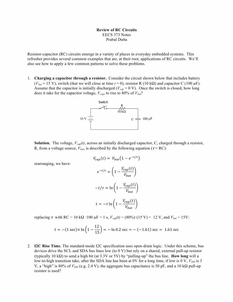
Prabal Dutta Resistor-capacitor (RC) circuits emerge in a variety of places in everyday embedded systems. This refresher provides several common examples that are, at their root, applications of RC circuits. We’ll also see how to apply a few common patterns to solve these problems. 1. Charging a capacitor through a resistor. Consider the circuit shown below that includes battery
(Vbat = 15 V), switch (that we will close at time t = 0), resistor R (10 kΩ) and capacitor C (100 µF). Assume that the capacitor is initially discharged (Vcap = 0 V). Once the switch is closed, how long does it take for the capacitor voltage, Vcap, to rise to 80% of Vbat?
Solution. The voltage, Vcap(t), across an initially discharged capacitor, C, charged through a resistor, R, from a voltage source, Vbat, is described by the following equation (τ = RC):
𝑉!"# 𝑡 = 𝑉!"# 1 − 𝑒!!/! rearranging, we have:
𝑒!!/! = 1 −𝑉!"#(𝑡)𝑉!"#
−𝑡/𝜏 = ln 1 −𝑉!!"(𝑡)𝑉!"#
𝑡 = −𝜏 ln 1 −𝑉!"#(𝑡)𝑉!"#
replacing τ with RC = 10 kΩ ·100 µF = 1 s, Vcap(t) = (80%)·(15 V) = 12 V, and Vbat = 15V:
𝑡 = − 1 sec × ln 1 −12 15
= − ln 0.2 sec = − −1.61 sec = 1.61 sec 2. I2C Rise Time. The standard-mode I2C specification uses open-drain logic. Under this scheme, bus
devices drive the SCL and SDA bus lines low (to 0 V) but rely on a shared, external pull-up resistor (typically 10 kΩ) to send a high bit (at 3.3V or 5V) by “pulling-up” the bus line. How long will a low-to-high transition take, after the SDA line has been at 0V for a long time, if low is 0 V, VDD is 3 V, a “high” is 80% of VDD (e.g. 2.4 V), the aggregate bus capacitance is 50 pF, and a 10 kΩ pull-up resistor is used?
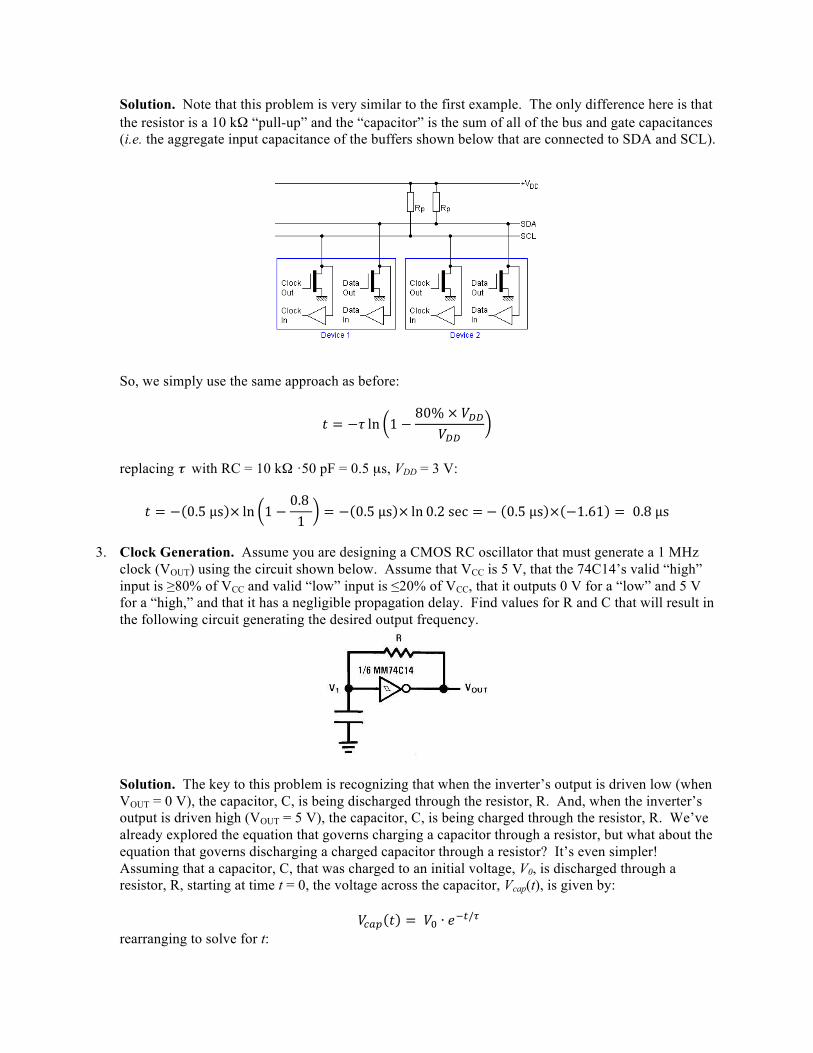
Solution. Note that this problem is very similar to the first example. The only difference here is that the resistor is a 10 kΩ “pull-up” and the “capacitor” is the sum of all of the bus and gate capacitances (i.e. the aggregate input capacitance of the buffers shown below that are connected to SDA and SCL).
So, we simply use the same approach as before:
𝑡 = −𝜏 ln 1 −80% × 𝑉!!
𝑉!!
replacing τ with RC = 10 kΩ ·50 pF = 0.5 µs, VDD = 3 V:
𝑡 = − 0.5 µμs × ln 1 −0.8 1
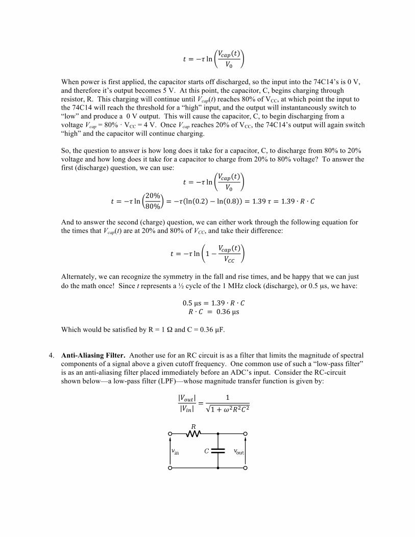
= − 0.5 µμs × ln 0.2 sec = − 0.5 µμs × −1.61 = 0.8 µμs 3. Clock Generation. Assume you are designing a CMOS RC oscillator that must generate a 1 MHz
clock (VOUT) using the circuit shown below. Assume that VCC is 5 V, that the 74C14’s valid “high” input is ≥80% of VCC and valid “low” input is ≤20% of VCC, that it outputs 0 V for a “low” and 5 V for a “high,” and that it has a negligible propagation delay. Find values for R and C that will result in the following circuit generating the desired output frequency.
Solution. The key to this problem is recognizing that when the inverter’s output is driven low (when VOUT = 0 V), the capacitor, C, is being discharged through the resistor, R. And, when the inverter’s output is driven high (VOUT = 5 V), the capacitor, C, is being charged through the resistor, R. We’ve already explored the equation that governs charging a capacitor through a resistor, but what about the equation that governs discharging a charged capacitor through a resistor? It’s even simpler! Assuming that a capacitor, C, that was charged to an initial voltage, V0, is discharged through a resistor, R, starting at time t = 0, the voltage across the capacitor, Vcap(t), is given by:
𝑉!"# 𝑡 = 𝑉! ∙ 𝑒!!/! rearranging to solve for t:
𝑡 = −𝜏 ln𝑉!"#(𝑡)𝑉!
When power is first applied, the capacitor starts off discharged, so the input into the 74C14’s is 0 V, and therefore it’s output becomes 5 V. At this point, the capacitor, C, begins charging through resistor, R. This charging will continue until Vcap(t) reaches 80% of VCC, at which point the input to the 74C14 will reach the threshold for a “high” input, and the output will instantaneously switch to “low” and produce a 0 V output. This will cause the capacitor, C, to begin discharging from a voltage Vcap = 80% · VCC = 4 V. Once Vcap reaches 20% of VCC, the 74C14’s output will again switch “high” and the capacitor will continue charging. So, the question to answer is how long does it take for a capacitor, C, to discharge from 80% to 20% voltage and how long does it take for a capacitor to charge from 20% to 80% voltage? To answer the first (discharge) question, we can use:
𝑡 = −𝜏 ln𝑉!"#(𝑡)𝑉!
𝑡 = −𝜏 ln20%80%
= −𝜏 ln 0.2 − ln 0.8 = 1.39 𝜏 = 1.39 ∙ 𝑅 ∙ 𝐶 And to answer the second (charge) question, we can either work through the following equation for the times that Vcap(t) are at 20% and 80% of VCC, and take their difference:
𝑡 = −𝜏 ln 1 −𝑉!"#(𝑡)𝑉!!
Alternately, we can recognize the symmetry in the fall and rise times, and be happy that we can just do the math once! Since t represents a ½ cycle of the 1 MHz clock (discharge), or 0.5 µs, we have:
0.5 µμs = 1.39 ∙ 𝑅 ∙ 𝐶 𝑅 ∙ 𝐶 = 0.36 µμs
Which would be satisfied by R = 1 Ω and C = 0.36 µμF.
4. Anti-Aliasing Filter. Another use for an RC circuit is as a filter that limits the magnitude of spectral
components of a signal above a given cutoff frequency. One common use of such a “low-pass filter” is as an anti-aliasing filter placed immediately before an ADC’s input. Consider the RC-circuit shown below—a low-pass filter (LPF)—whose magnitude transfer function is given by:
|𝑉!"#||𝑉!"|
=1
1 + 𝜔!𝑅!𝐶!
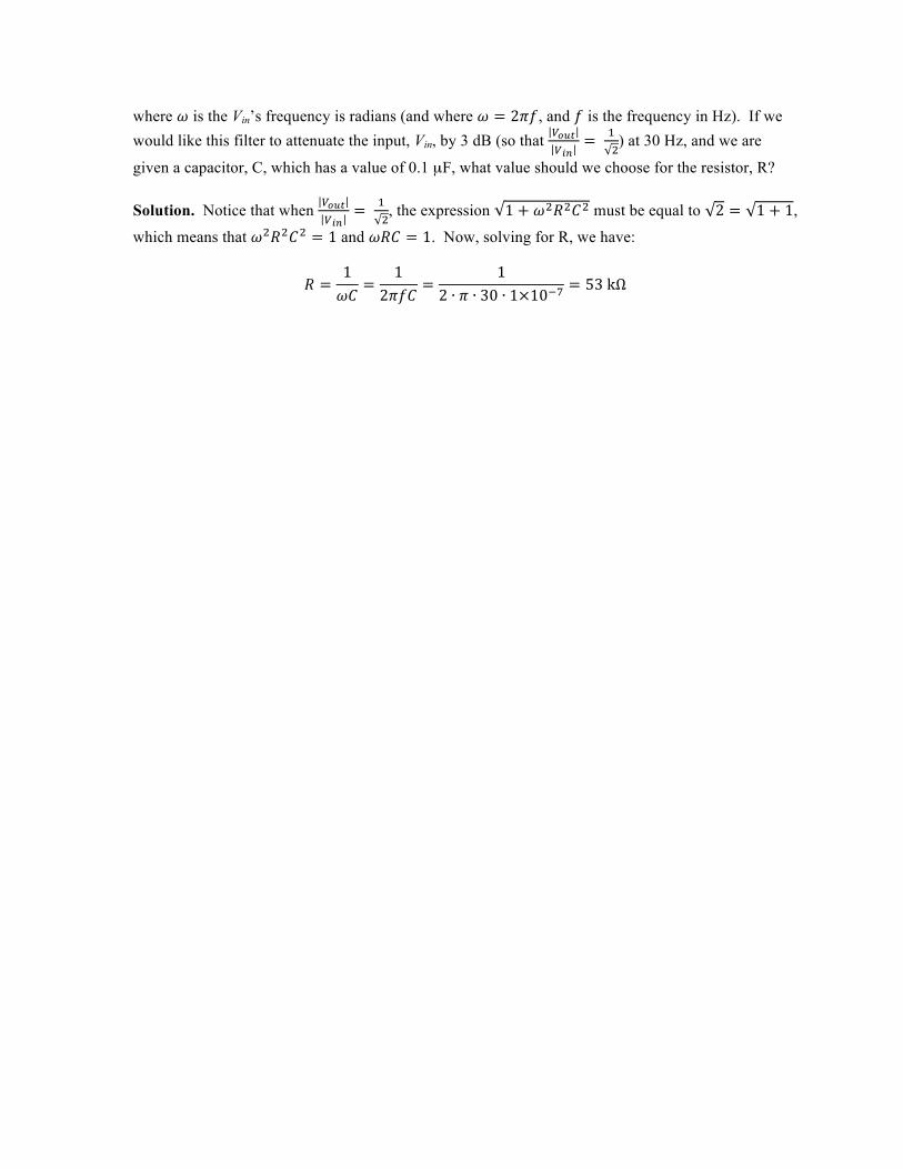
where 𝜔 is the Vin’s frequency is radians (and where 𝜔 = 2𝜋𝑓, and 𝑓 is the frequency in Hz). If we would like this filter to attenuate the input, Vin, by 3 dB (so that !!"#
!!"= !
!) at 30 Hz, and we are
given a capacitor, C, which has a value of 0.1 µF, what value should we choose for the resistor, R? Solution. Notice that when !!"#
!!"= !
!, the expression 1 + 𝜔!𝑅!𝐶! must be equal to 2 = 1 + 1,
which means that 𝜔!𝑅!𝐶! = 1 and 𝜔𝑅𝐶 = 1. Now, solving for R, we have:
𝑅 =1𝜔𝐶
=1
2𝜋𝑓𝐶=
12 ∙ 𝜋 ∙ 30 ∙ 1×10!!
= 53 kΩ