Embed Size (px)
Citation preview
Review of the Canadian EV-Safety Thermal
Propagation Principles
Steven RecoskieResearch Officer
Energy, Mining and Environment – Ottawa
613-998-9786
Co-authors : NRC : Dean MacNeil, Joel Perron, Sebastien Touchette, Giulio
Torlone, Transport Canada : Kyle Hendershot
Dec 3-5, 2019 EVS 19 - GTR Berlin, Germany
Outline
2
• Review
• Discussion on lingering questions
• What are we simulating:
ISC or locally initiated TR triggered by unspecified cause
• Our approach
• How to define boundary and set conditions for TRIM
• Test implementation
• Upcoming Test Program
• Conclusion
Thermal propagation requirement in current GTR draft
(Review)
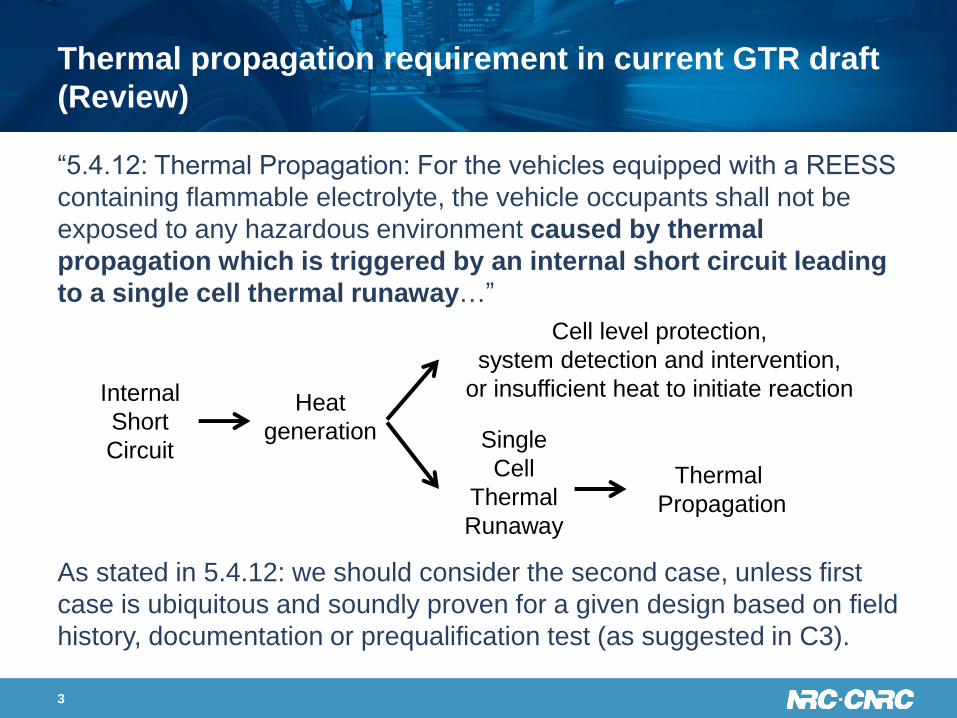
“5.4.12: Thermal Propagation: For the vehicles equipped with a REESS
containing flammable electrolyte, the vehicle occupants shall not be
exposed to any hazardous environment caused by thermal
propagation which is triggered by an internal short circuit leading
to a single cell thermal runaway…”
As stated in 5.4.12: we should consider the second case, unless first
case is ubiquitous and soundly proven for a given design based on field
history, documentation or prequalification test (as suggested in C3).
3
Internal
Short
Circuit
Heat
generation Single
Cell
Thermal
Runaway
Thermal
Propagation
Cell level protection,
system detection and intervention,
or insufficient heat to initiate reaction
Introduction and Background
4
• In the field, latent defects are very difficult to detect, but they have led to
significant safety events in numerous industries.
• It has been documented that these latent defects, from experienced and
reputable manufacturers, are estimated to occur at 0.1 to 1 ppm
probability (well beyond 6 σ).
• These defects can not be effectively removed at the manufacturing or
pack assembly stage by rigorous screening.
• So how can a manufacturer guarantee that it can be detected before
initiating side reactions? Especially if one is not monitoring these changes
quickly enough and with enough precision for all cells in the battery pack.
• There is no question; industry is working on solutions, but will they be
sufficient? Will these rigorous solutions be applied unilaterally across all
the various industry suppliers?
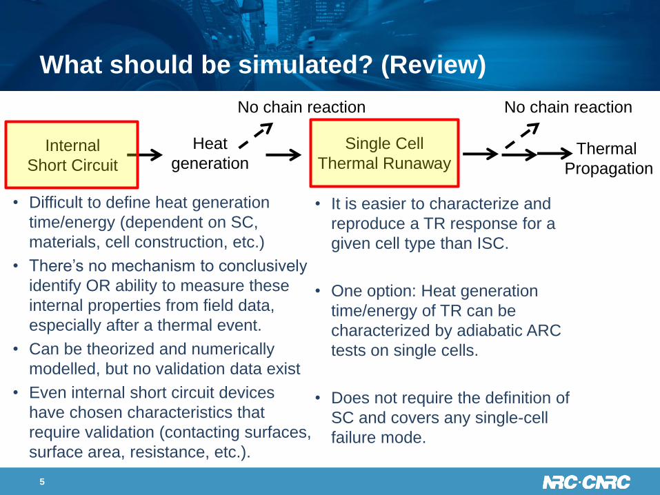
What should be simulated? (Review)
• Difficult to define heat generation
time/energy (dependent on SC,
materials, cell construction, etc.)
• There’s no mechanism to conclusively
identify OR ability to measure these
internal properties from field data,
especially after a thermal event.
• Can be theorized and numerically
modelled, but no validation data exist
• Even internal short circuit devices
have chosen characteristics that
require validation (contacting surfaces,
surface area, resistance, etc.).
• It is easier to characterize and
reproduce a TR response for a
given cell type than ISC.
• One option: Heat generation
time/energy of TR can be
characterized by adiabatic ARC
tests on single cells.
• Does not require the definition of
SC and covers any single-cell
failure mode.
5
Internal
Short Circuit
Heat
generation
Single Cell
Thermal RunawayThermal
Propagation
No chain reaction No chain reaction
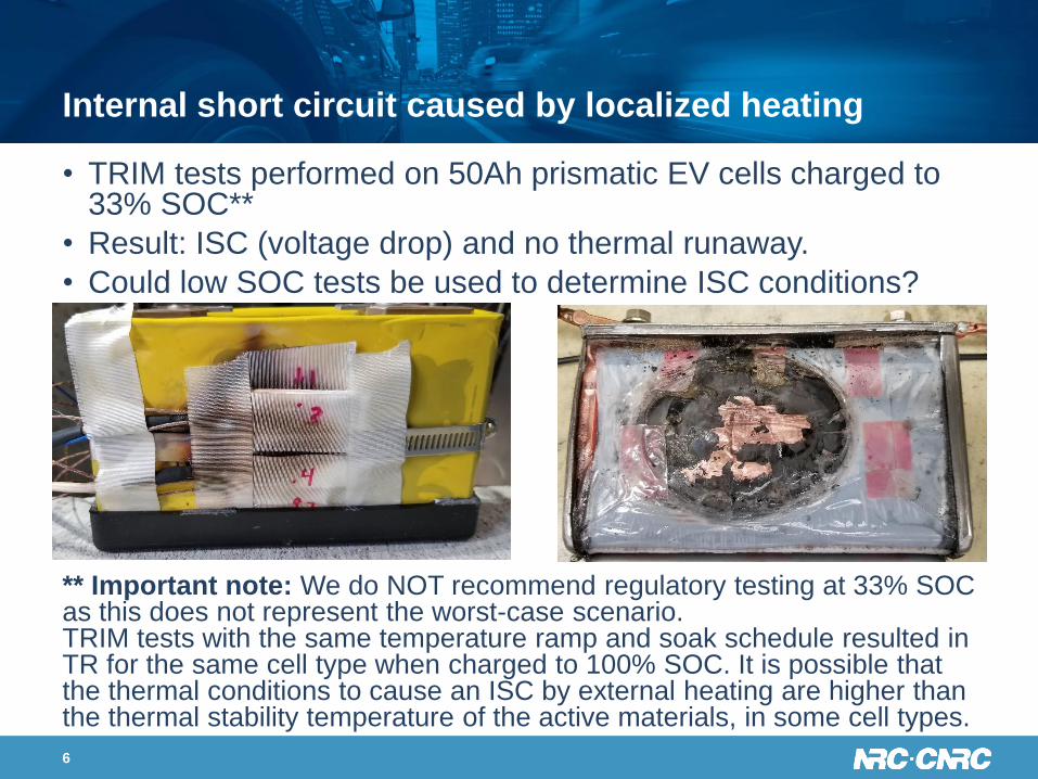
Internal short circuit caused by localized heating
• TRIM tests performed on 50Ah prismatic EV cells charged to 33% SOC**
• Result: ISC (voltage drop) and no thermal runaway.
• Could low SOC tests be used to determine ISC conditions?
** Important note: We do NOT recommend regulatory testing at 33% SOC as this does not represent the worst-case scenario. TRIM tests with the same temperature ramp and soak schedule resulted in TR for the same cell type when charged to 100% SOC. It is possible that the thermal conditions to cause an ISC by external heating are higher than the thermal stability temperature of the active materials, in some cell types.
6
7
• Any ISC test (internally or externally activated) requires ISC
data to emulate. External short circuit data from individual
cells could be used, but is this realistic of a true internal short?
• Can we choose what is a realistic reproduction of an internal
short circuit? Need to define the Contact areas, Resistances
and Power for every cell.
• Results from literature, using engineered cells, show
numerous types of short circuits and only some result in
thermal runaway.
How to implement ISC Test in a regulatory
environment?
How to implement ISC Test in a regulatory
environment?
8
• It is widely accepted that ISC can occur and that TR due to ISC
is a potential outcome (inherent of the current LIB technology
and observed in other industries using LIBs of similar type).
Our Proposed Method
• In our opinion, the battery pack/vehicle design should mitigate
the worst-case scenario of an ISC:• The generation of a local hot spot that provides sufficient heat to initiate
the self-propagating exothermic decomposition of active material leading
to a thermal runaway within a single cell.
(Exceptions could be possible if it can be proven that this worst-
case scenario cannot exist for a given design or technology.)
9
• Thus, we need to design a test to determine the response of
the pack/vehicle towards thermal runaway initiated from a
localized thermal event with unspecified root cause.
• It is critical that this testing occurs without biasing any pack or
vehicle level safety system, any neighboring cells and without
the addition of significant energy to the system.
• Our full-scale testing has shown that single cell thermal
runaway and even some extent of thermal propagation can be
tolerable without creating a hazardous environment for
occupants/bystanders.
OUR APPROACH
OUR APPROACH - Visual Implementation
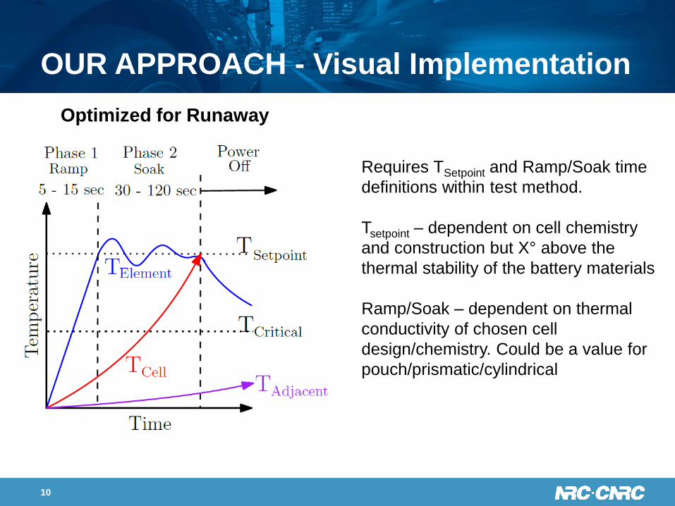
Optimized for Runaway
Requires TSetpoint and Ramp/Soak time
definitions within test method.
Tsetpoint – dependent on cell chemistry
and construction but X° above the
thermal stability of the battery materials
Ramp/Soak – dependent on thermal
conductivity of chosen cell
design/chemistry. Could be a value for
pouch/prismatic/cylindrical
10
Defining boundary conditions
11
11
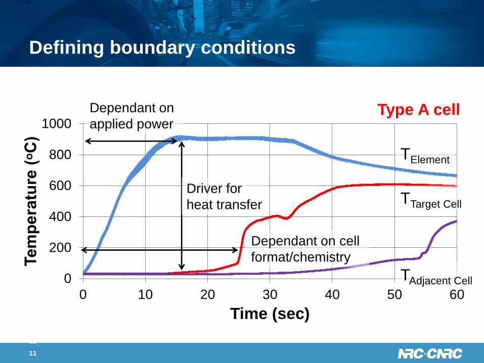
0
200
400
600
800
1000
0 10 20 30 40 50 60
Te
mp
era
ture
(ᵒC
)
Time (sec)
Driver for
heat transfer
Dependant on
applied power
Dependant on cell
format/chemistry
TElement
TTarget Cell
TAdjacent Cell
Type A cell
Defining boundary conditions
• This is a question of heat transfer. How can you get
sufficient heat INTO a cell, to initiate internal self-
propagating exothermic reactions (or ISC, if possible), from
the outside without significantly affecting the neighboring
environment?
• We have begun a modelling activity in hand with validation
from experimental results.
• There are many things to consider: casing material, electrode
material, cell size, neighboring environment, internal construction
etc..
12
(ex.
Crit
ical
tem
p. 2
20°C
)
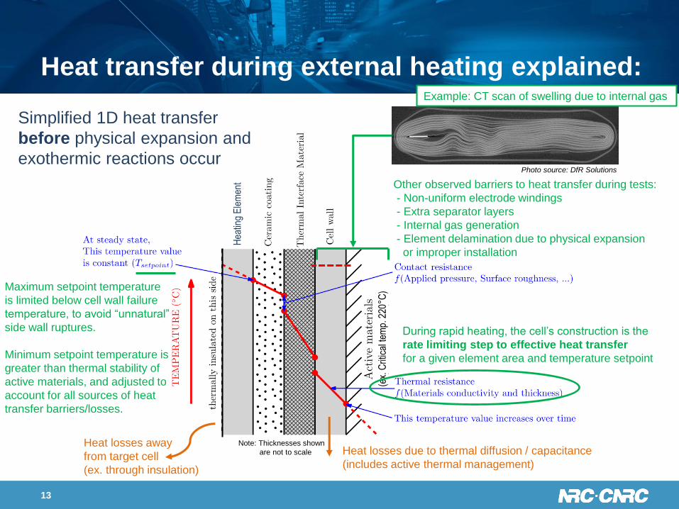
Heat transfer during external heating explained:
13
Heat losses away
from target cell
(ex. through insulation)
Heat losses due to thermal diffusion / capacitance
(includes active thermal management)
During rapid heating, the cell’s construction is the
rate limiting step to effective heat transfer
for a given element area and temperature setpoint
Maximum setpoint temperature
is limited below cell wall failure
temperature, to avoid “unnatural”
side wall ruptures.
Minimum setpoint temperature is
greater than thermal stability of
active materials, and adjusted to
account for all sources of heat
transfer barriers/losses.
Other observed barriers to heat transfer during tests:
- Non-uniform electrode windings
- Extra separator layers
- Internal gas generation
- Element delamination due to physical expansion
or improper installation
Note: Thicknesses shown
are not to scale
Simplified 1D heat transfer
before physical expansion and
exothermic reactions occurPhoto source: DfR Solutions
Example: CT scan of swelling due to internal gas
Hea
ting
Ele
men
t
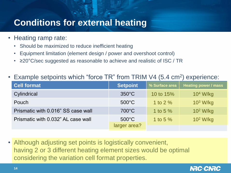
Conditions for external heating
• Heating ramp rate:
• Should be maximized to reduce inefficient heating
• Equipment limitation (element design / power and overshoot control)
• ≥20°C/sec suggested as reasonable to achieve and realistic of ISC / TR
• Example setpoints which “force TR” from TRIM V4 (5.4 cm2) experience:
• Although adjusting set points is logistically convenient,
having 2 or 3 different heating element sizes would be optimal
considering the variation cell format properties.
14
% Surface area Heating power / mass
10 to 15% 104 W/kg
1 to 2 % 103 W/kg
1 to 5 % 102 W/kg
1 to 5 % 102 W/kg
Cell format Setpoint
Cylindrical 350°C
Pouch 500°C
Prismatic with 0.016” SS case wall 700°C
Prismatic with 0.032” AL case wall 500°C
larger area?
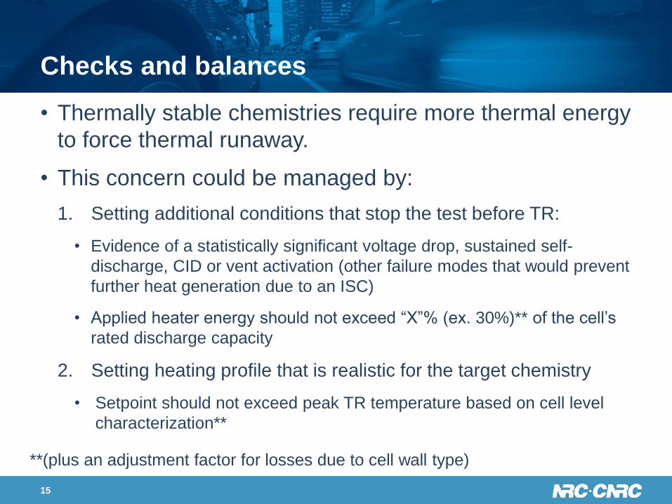
Checks and balances
• Thermally stable chemistries require more thermal energy
to force thermal runaway.
• This concern could be managed by:
1. Setting additional conditions that stop the test before TR:
• Evidence of a statistically significant voltage drop, sustained self-
discharge, CID or vent activation (other failure modes that would prevent
further heat generation due to an ISC)
• Applied heater energy should not exceed “X”% (ex. 30%)** of the cell’s
rated discharge capacity
2. Setting heating profile that is realistic for the target chemistry
• Setpoint should not exceed peak TR temperature based on cell level
characterization**
**(plus an adjustment factor for losses due to cell wall type)
15
Test implementation
• Ideally, one single method could be applied to all vehicle
designs to reduce the challenge of finding equivalency.
• Since TR conditions will be different for each cell type,
the test method should be allowed to be tailored based
on the cell properties (ex. capacity, format, chemistry).
These adjustments can be established through single-
cell characterization.
• Test methods must consider how they could be
implemented at the vehicle level and significant
modifications to BMS, REESS seal integrity, or thermal
management system should not be permitted.
16
Test implementation
• We have shown previously how active thermal management
can play a significant role in the extent of thermal propagation
and cannot be ignored within test designs
• We have shown how, in some module/pack designs, there can
be no measureable change in voltage during a single cell
thermal runaway, thus voltage drop should not be used as the
sole/primary indicator of a cell failure
• We found the vehicle-level was easier to execute (no custom
cooling/mounts/instrumentation) and most representative of
actual field conditions.
To be technology neutral, the full system level response
must be considered during thermal propagation testing.
17
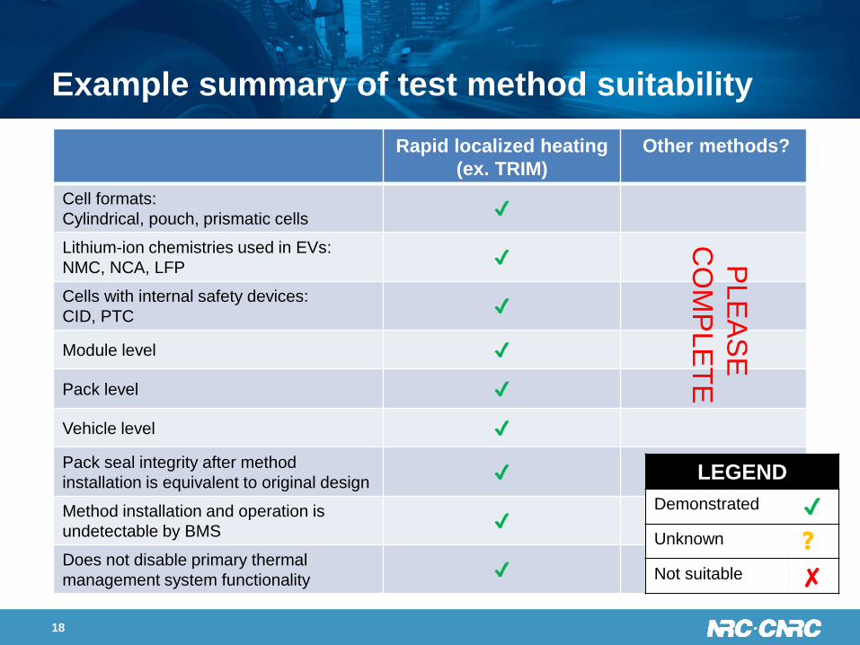
Example summary of test method suitability
Rapid localized heating
(ex. TRIM)
Other methods?
Cell formats:
Cylindrical, pouch, prismatic cells✔
Lithium-ion chemistries used in EVs:
NMC, NCA, LFP✔
Cells with internal safety devices:
CID, PTC✔
Module level ✔
Pack level ✔
Vehicle level ✔
Pack seal integrity after method
installation is equivalent to original design✔
Method installation and operation is
undetectable by BMS✔
Does not disable primary thermal
management system functionality✔
18
LEGEND
Demonstrated ✔
Unknown ❓
Not suitable ✘
PLE
AS
E
CO
MP
LE
TE
Future Topics and test Program
19
• Comparison of TRIM heater with another high heat flux heater
• Vehicle Level test Program (Spring 2020):
• 2014 Tesla Model S and
• 2019 Nissan Leaf
• OEM help/experience is encouraged
• Refining set-point temperature and dwell times
via thermal modelling
• We are working within ISO to create a standard test for
thermal propagation using rapid external heating (generic).
Acknowledgements
The authors gratefully acknowledge financial support for
this project from Transport Canada through its Motor
Vehicle Standards - Research and Development Branch,
ecoTechnologies for Vehicles Program and the National
Research Council through its Vehicle Propulsion
Technologies Program.
Thank you for your kind attention!
Any Questions or Comments
20