Embed Size (px)
Citation preview

ORNL/TM-2003/209
REVIEW OF THE STATE-OF-THE-ART IN POWER ELECTRONICS SUITABLE FOR
10-KW MILITARY POWER SYSTEMS
R. H. Staunton B. Ozpineci T. J. Theiss
L. M. Tolbert* Oak Ridge National Laboratory
*The University of Tennessee
(Joint appointment with the Oak Ridge National Laboratory and the University of Tennessee)

This report was prepared as an account of work sponsored by an agency of the United States Government. Neither the United States Government nor any agency thereof, nor any of their employees, makes any warranty, express or implied, or assumes any legal liability or responsibility for the accuracy, completeness, or usefulness of any information, apparatus, product, or process disclosed, or represents that its use would not infringe privately owned rights. Reference herein to any specific commercial product, process, or service by trade name, trademark, manufacturer, or otherwise, does not necessarily constitute or imply its endorsement, recommendation, or favoring by the United States Government or any agency thereof. The views and opinions of authors expressed herein do not necessarily state or reflect those of the United States Government or any agency thereof.

ORNL/TM-2003/209
Engineering Science & Technology Division
REVIEW OF THE STATE-OF-THE-ART IN POWER ELECTRONICS SUITABLE FOR 10KW
MILITARY POWER SYSTEMS
R. H. Staunton B. Ozpineci T. J. Theiss
L. M. Tolbert
October 2003
Manuscript completed: September 2003
Date Published: December 2003
Prepared by the OAK RIDGE NATIONAL LABORATORY
Oak Ridge, Tennessee 37831 managed by
UT-BATTELLE, LLC for the
U.S. DEPARTMENT OF ENERGY Under contract DE-AC05-00OR22725

ii
TABLE OF CONTENTS
Page LIST OF FIGURES .............................................................................................................................. iv LIST OF TABLES................................................................................................................................ v ACRONYMS, ABBREVIATIONS, AND INITIALISMS .................................................................. vi EXECUTIVE SUMMARY .................................................................................................................. viii ABSTRACT.......................................................................................................................................... x 1. INTRODUCTION ........................................................................................................................ 1 1.1 BACKGROUND ................................................................................................................ 1 1.2 PURPOSE OF REPORT .................................................................................................... 1 1.2.1 Scope of Work ....................................................................................................... 2 1.2.2 Report Outline........................................................................................................ 2 1.3 APPROACH ...................................................................................................................... 3 2. REQUIREMENTS AND TOPOLOGIES FOR MOBILE POWER SUPPLIES ......................... 5 2.1 POWER REQUIREMENTS FOR ARMY APPLICATIONS............................................ 5 2.2 ALTERNATOR SYSTEM AND MANUFACTURERS ................................................... 5 2.3 SURGE REQUIREMENTS FOR THE TEP SYSTEM ..................................................... 7 2.4 LIKELY INVERTER TOPOLOGIES OF THE POWER ELECTRONICS ...................... 8 2.4.1 Circuit Topologies for Mobile Power Supplies ..................................................... 8 2.4.2 Active Rectification ............................................................................................... 11 2.4.3 Energy Storage....................................................................................................... 13 3. MARKET SURVEY OF COMMERCIALLY AVAILABLE POWER ELECTRONICS ......... 15 3.1 AVALIBILITY OF RELIABLE COMMERCIAL INVERTERS...................................... 15 3.2 PACKAGING OF COMMERCIAL INVERTERS ............................................................ 15 3.3 MOTOR DRIVE AND MICROTURBINE CIRCUITRY AND FEATURES................... 19 3.4 DATA OBTAINED ON MOTOR DRIVE MANUFACTURERS..................................... 21
3.5 DATA OBTAINED ON DISTRIBUTED ENERGY RESOURCES INVERTER MANUFACTURERS ......................................................................................................... 23
3.6 SURVEY OF MOTOR DRIVE MANUFACTURERS...................................................... 25 3.7 SURVEY OF DISTRIBUTED ENERGY RESOURCES INVERTER MANUFACTURERS ......................................................................................................... 33 3.8 ASSESSMENT AND RANKING OF INVERTER MANUFACTURERS ....................... 36 3.9 VARIABLE-SPEED ALTERNATIVE .............................................................................. 41 4. ADDITIONAL DESIGN CONSIDERATIONS .......................................................................... 44 4.1 EFFECTS OF EMI ON THE TQM SYSTEM ................................................................... 44 4.1.1 Predicted Effects of a HEMP................................................................................. 44 4.1.2 HEMP Test Facility ............................................................................................... 47 4.1.3 Protective Methods against EMP........................................................................... 48

iii
4.1.4 TEP System Application........................................................................................ 48 4.2 RELIABILITY ISSUES ..................................................................................................... 49 4.2.1 Effects of Environmental Stressors on Reliability ................................................. 49 4.2.2 Upper Bounds on MTBF ....................................................................................... 52 5. DIRECTLY APPLICABLE ADVANCES IN TECHNOLOGY ................................................. 53 5.1 WIDE-BANDGAP SEMICONDUCTORS FOR USE IN POWER APPLICATIONS ..... 53 5.1.1 Properties of Wide-Bandgap Semiconductors ....................................................... 54 5.1.2 Commercial Availability of Wafers ....................................................................... 59 5.1.3 Commercially Available Wide-Bandgap Semiconductor-Based Power Devices.. 59 5.1.4 Forecasting the Future............................................................................................ 59 5.2 CRYOGENIC POWER ELECTRONICS TECHNOLOGIES REVIEW .......................... 60 5.2.1 Cryogenic Power Device ....................................................................................... 60 5.2.2 Cryogenic Power Converters ................................................................................. 61 5.2.3 CPE System and Control ....................................................................................... 65 6. SUMMARY AND RECOMMENDATIONS .............................................................................. 67 6.1 TECHNOLOGY SUMMARY............................................................................................ 67 6.2 RECOMMENDATIONS FOR PRODUCT DEVELOPMENT ......................................... 68 7. REFERENCES ............................................................................................................................ 70 APPENDIX A – PRODUCT INFORMATION FROM MOTOR DRIVE VENDORS ..................... 74 APPENDIX B – PRODUCT INFORMATION FROM DISTRIBUTED ENERGY RESOURCES VENDORS ........................................................................................................................................ 81 B.1 VENDORS AND MANUFACTURERS............................................................................ 81 B.2 ADDITIONAL VENDORS................................................................................................ 88 DISTRIBUTION.................................................................................................................................... 90

iv
LIST OF FIGURES Figure Page 2.1 Simplified diagram of an inverter-based power source supplied by an energy storage device and an alternator............................................................................. 8 2.2 Simplified diagrams of dc link converter power converter circuits........................................ 9 2.3 Simplified diagram of a cycloconverter ................................................................................. 10 2.4 Simplified diagram of a HFLC............................................................................................... 10 2.5 Alternator voltage rectified and filtered in a simple rectifier/capacitor circuit to create a dc voltage with ripple................................................................................. 11 3.1 Well-packaged motor drive with inverter power electronics located in the upper left corner of the casing behind layers of circuit boards and the front display............. 16 3.2 Large cabinet with compact inverter module ......................................................................... 17 3.3 Capstone microturbine (30 kW) and Elliot microturbine (80 kW)......................................... 17 3.4 Bowman inverter location....................................................................................................... 18 3.5 Block diagram of an ac motor drive system without modification......................................... 19 3.6 Block diagram of a motor drive inverter modified for the TEP system application............... 20 3.7 KEBCO motor drive............................................................................................................... 32 3.8 Solectria inverter..................................................................................................................... 35 3.9 Exeltech inverter..................................................................................................................... 36 3.10 Youtility’s 25 KVA power converter ..................................................................................... 42 4.1 HEMP event area of illumination relative to a transmission line and tower .......................... 48 4.2 Power consumption trends for computer microprocessors..................................................... 50 4.3 Relationship between failure rate and device temperature ..................................................... 51 4.4 Classic bathtub curve for reliability is useful for establishing MTBF limits.......................... 52 5.1 Maximum Breakdown Voltage of a power device at the same doping density normalized to Si ......................................................................................................... 55 5.2 Width of the drift region for each material at different breakdown voltages ......................... 56 5.3 Resistance of the drift region for each material at different breakdown voltages .................. 56 5.4 On-resistance of a 600-V, 35-A power MOSFET at 300 K and 77 K.................................... 60 5.5 Converter efficiency vs. temperature...................................................................................... 62 5.6 Converter component losses vs. temperature ......................................................................... 62 5.7 Switching waveforms of power MOSFET in a boost converter (a) RT and (b) LNT ............ 63 5.8 MOSFETs switching waveforms at LNT (a) with regular gate drive circuit and (b) with modified gate drive circuit design............................................................................. 64 5.9 Switching waveforms comparison at LNT (a) hard switching and (b) hybrid soft switching ........................................................................................................ 64 5.10 A single phase of a soft switching inverter ............................................................................ 65 5.11 Current mode PWM control integrated circuit ...................................................................... 66

v
LIST OF TABLES Table Page 2.1 Examples of technology-based alternator developers/manufacturers........................................ 6 2.2 Comparison of rectification techniques/components ................................................................. 12 2.3 Qualitative comparison of battery-based and ultracapacitor-based energy storage................... 14 3.1 Motor drive vendors and product lines ...................................................................................... 22 3.2 Motor drive vendors and internet sites....................................................................................... 23 3.3 Power converter and/or DG manufacturers whose products are in production and available on the market ..................................................................................... 24 3.4 Manufacturers and internet urls ................................................................................................. 25 3.5 Summary of initial best prospects for inverter suppliers for proposed TEP systems ............... 38 3.6 Scoring of parameters for each potential inverter supplier ........................................................ 40 3.7 Potential inverter supplier companies listed by ranking ............................................................ 41 5.1 Physical characteristics of Si and main wide-bandgap semiconductors .................................... 54 5.2 Main figures of merit for wide-bandgap semiconductors compared with Si........................... 57 B.1 Microturbine manufacturer, operating parameters, and general features................................. 83 B.2 Microturbine ancillary services and special features ............................................................... 85 B.3 Microturbine circuit topology, components, special specifications, and power quality concerns ............................................................................................................ 86 B.4 Present industry needs from the prospective of power converter manufacturers .................... 87

vi
ACRONYMS, ABBREVIATIONS, AND INITIALISMS ARL Army Research Laboratory C3I Command, Control, Communications and Intelligence CECOM Communications and Electronics Command CFO critical flashover CPEs cryogenic power electronics CW continuous wave DER distributed energy resources DG distributed generation DMGIs digital microgrid inverters DOE Department of Energy DPC digital power controller DSP digital signal processor ECUs environmental control units EMC electromagnetic compatibility EMI electromagnetic interference EMP electromagnetic pulse FET field-effect transistor GaN gallium nitride GEIS/F GE Industrial Systems/Fuji HEMP high-altitude electromagnetic pulse HEV hybrid electric vehicle HFLC high-frequency link converter HTS high-temperature superconducting IGBTs insulated gate bipolar transistors LNT liquid nitrogen temperature MHD-EMP magnetohydrodynamic electromagnetic pulse MOSFET metal oxide semiconductor field effect transistor MOV metal oxide varistors MTBF mean time between failures NASA National Aeronautics and Space Administration NEMA National Electrical Manufacturers Association OFW objective force warrior ORNL Oak Ridge National Laboratory PID proportional integral derivative PM permanent magnet PMHH permanent magnet hybrid homopolar PM-MEP Program Manager for Mobile Electric Power POE point of entry PV photovoltaic PWM pulse-width modulated RDEC Research, Development, and Engineering Command RFI radio frequency interference RT room temperature SBCT Stryker Brigade Combat Team SELDS shielded enclosure leak detection survey Si silicon SiC silicon carbide SMES superconducting magnetic energy storage

vii
SR switched reluctance TEP Tactical Electrical Power TQG tactical quiet generator TVC torque vector control VC vector control VSG variable-speed generation
viii
EXECUTIVE SUMMARY In early 2003, U.S. Army Communications and Electronics Command (CECOM) Research, Development and Engineering Command (RDEC) directed the Oak Ridge National Laboratory (ORNL) to thoroughly investigate the potential of using commercially produced inverters in Tactical Electrical Power (TEP) systems, specifically in the 10-kW size range. Adapting inverters for genset use is justified on the basis that state-of-the-art inverters offer important advantages in weight reduction, improved efficiency, better performance in a wider range of generator operating conditions, greater versatility and adaptability, and excellent reliability. ORNL set out to survey the inverter market, identify the best manufacturers, and explore technology improvements expected in years to come. The study begins by describing the technical requirements of the TEP system power supplies, discussing how the system can be best optimized by integrating the alternator and inverter designs, outlining general requirements included in acceptance testing, and identifying other developmental considerations. The study identifies and describes a number of inverter circuit topologies that are well suited to meet the Army’s near-term needs. The study also proposes and describes other more advanced and highly versatile circuit designs that could meet additional requirements that may arise years into the future. Following the introduction of numerous general requirements and system design considerations and alternatives, the ORNL study proceeds to a market survey. This survey identifies inverters that are “market proven” by both high production volume and years of service in the field. This approach ensures that the reliability and performance of such products can be readily demonstrated using operation data provided by the survey. The goal of identifying market-proven products is consistent with identifying inverters suitable for meeting the near-term needs of CECOM RDEC with high assurance. The survey carefully focuses on inverter system packaging, circuit features, innovation, and reliability. Based on the survey, the study presents summary information pertaining to several inverter models and inverter series/families marketed by both large and intermediate-sized vendors/manufacturers. The inverters were found in both the industrial motor drive industry and in the emerging distributed power generation industry, since these were essentially the only sources of 3-phase inverters in the power range of interest. The study closely considers survey responses received from several manufacturers and ranks the manufacturers based on criteria such as apparent or demonstrated interest, technical highlights, environmental tolerance (thermal robustness), production levels, and estimated cost. Separate from the main survey and analysis, information was also obtained on a new manufacturer of highly innovative, variable-speed, power electronics. Based primarily on the rankings, ORNL believes that excellent products are available from the following manufacturers and that these products are readily adaptable to meet the program needs:
• Solectria Corporation • Omron IDM Controls • US Drives • Square D • Baldor • Capstone Turbine Corp. • KEBCO, Inc. • Youtility, Inc.
ORNL investigated additional design considerations such as the vulnerability to an electromagnetic pulse (EMP) and its predicted effects on electronic and electrical systems. The discussion includes a description of acceptable testing methodology in an EMP environment, EMP protection methods, and related issues. The EMP vulnerability study is followed by a discussion of reliability issues or considerations in assessing the performance of inverter systems presently available in the commercial market.

ix
The study also considers research relating to power electronics that would be potentially applicable to advancing inverter system technology. One important technology advancement would be the development of wide-bandgap semiconductors. Recent development advances have caused silicon semiconductor technology to approach theoretical material limits; however, active switching power device requirements for many applications have changed to the point that Si-based power devices cannot meet them. The requirements include higher blocking voltages, switching frequencies, efficiency, and reliability. Therefore, new semiconductor materials for power device applications are needed. For high-power requirements, wide-bandgap semiconductors such as silicon carbide (SiC), gallium nitride (GaN), and diamond, with their superior electrical properties, are likely near-term candidates. The study compares wide-bandgap semiconductors with respect to their promise and applicability for power applications and predicts the future of these power device semiconductor materials. Other crucial technology advancements may come from ongoing cryogenic device and circuit research in diverse areas. For example, the cryogenic power device research indicates that the performance of majority carrier metal oxide semiconductor field effect transistor (MOSFET) devices improves with decreasing temperature whereas the opposite is the case for minority carrier devices. Second, cryogenic power electronics (CPE) using high-temperature superconducting (HTS) technology to achieve ultra-high efficiency and high power density may be possible. Finally, new material technologies for implementing converter control algorithms show significant advantages over present bipolar technology. The overall study confirmed with high confidence that there are multiple sources of high-quality inverter systems that, in concert with the alternator, can be designed, adapted, and integrated into a reliable and versatile 10-kW mobile power supply system. The study also shows high promise for future adaptations and technical enhancements that will ensure that the inverter and inverter controller can continue to play a primary role in reshaping mobile electric power supplies to meet future missions for many years to come.

x
ABSTRACT The purpose of this report is to document the technological opportunities of integrating power electronics-based inverters into a TEP system, primarily in the 10-kW size range. The proposed enhancement offers potential advantages in weight reduction, improved efficiency, better performance in a wider range of generator operating conditions, greater versatility and adaptability, and adequate reliability. In order to obtain strong assurance of the availability of inverters that meet required performance and reliability levels, a market survey was performed. The survey obtained positive responses from several manufacturers in the motor drive and distributed generation industries. This study also includes technology reviews and assessments relating to circuit topologies, reliability issues, vulnerability to pulses of electromagnetic energy, potential improvements in semiconductor materials, and potential performance improvement through cryogenics.

1
1. INTRODUCTION This report and underlying work is a part of the Tactical Electrical Power (TEP) Program conducted by the U.S. Army Communications and Electronics Command (CECOM) Research, Development, and Engineering Command (RDEC) under the sponsorship of the Department of Defense Program Manager for Mobile Electric Power (PM-MEP). The work was performed by personnel at the U.S. Department of Energy (DOE) Oak Ridge National Laboratory (ORNL) in close cooperation with CECOM RDEC personnel. The purpose of this report is to document the ORNL review in the state of the art in commercial power electronics suitable for 10-kW military power systems. 1.1 BACKGROUND The need for reliable electrical power in the battlefield is a requirement that cuts across all services and all locations and will be increasing in the near future. In fact, according to the PM-MEP Web page, “Electric power, provided primarily by mobile generators in the combat zone, is the lifeblood of the Armed Forces. For without it, all the technical wizardry of modern warfare—the Weapons Systems, the Command, Control, Communications and Intelligence (C3I) Systems, and Logistics Support Systems — is useless.” The Army seeks to develop power electronics and controls for use on TEP sources for the objective force warrior (OFW) and for integration into Stryker Brigade Combat Team (SBCT) vehicle-based applications. The CECOM RDEC has identified several operational and performance-based problems with power electronics — and their many associated domains — as they are applied to TEP sources and on tactical vehicles. Therefore, the Army seeks to
• Investigate the commercial market to identify state-of-the-art power electronics, which can be adapted and integrated to develop the next generation of TEP sources that address the Army’s transformation needs for the OFW.
• Identify recent developments and future trends in all aspects of power electronics and evaluate these developments and trends to determine where best to apply future Army technical base funding.
• Research the failures encountered when using power electronic technologies on TEP sources and develop potential corrective measures.
Previous work conducted by ORNL for the U. S. military dealt with the entire TEP system. This effort is reported under the titles Development of Proof-of-Concept Units for the Advanced Medium-sized Mobile Power Sources (AMMPS) Program [1] and Advanced Power Generation Systems for the 21st Century: Market Survey & Recommendations for a Design Philosophy [2]. 1.2 PURPOSE OF REPORT The purpose of this report is to review and document results of the ORNL investigation into the state-of-the-art of power electronics that might be suitable for 10-kW military electrical systems. Through this effort, ORNL seeks to provide the Army valuable information on problems associated with the use of power electronic technology on TEP sources and tactical vehicles. In addition, this effort will examine the commercial market and academia to determine the state of the art, identify advances in power electronic technology, and apply the applicable systems and advances to resolve the problems found in tactical equipment.

2
1.2.1 Scope of Work The power electronics must be capable of withstanding military environments. Electronic components must withstand temperature extremes between –50 oF (−45 oC) to +140 oF (60 oC) at any possible relative humidity, endure shock and vibration, prevent corrosion, include electromagnetic interference (EMI) protection, produce low signature detection, have long life cycles, be easy to maintain, and minimize harmonic distortion. The power electronics shall withstand transients associated with the startup of large motor loads, such as environmental control units (ECUs). The following tasks were performed by ORNL personnel for the CECOM RDEC as a part of this investigation. a) Survey and evaluate commercially available power electronics that are applicable for the 10-kW
power range. The market survey and evaluation included • A baseline on power electronics topologies that are compatible for application with tactical quiet
generator (TQG) or TEP generator set designs. Assessments were made to determine if the desired goals are achievable.
• Availability of commercial power electronics. • Effects of EMI on this technology • Recommendations for best design approach/applications that offer improvements over the current
size, weight, and cost of the TQG 10-kW generator set design. b) Investigate and identify research efforts pursued by industry and academia that are aimed at
overcoming the operational and performance problems associated with current power electronics designs/techniques. Results include • A summary of research and development currently taking place that will advance this technology
and will be available in the next 2–3 years. • Recommendations for those emerging power electronics (with and without alternators) that best
suit the needs of the tactical battlefield
c) Investigate potential alternative power electronics topologies/systems to power resistive and motor loads.
During the timeframe of this study, a separate effort will be conducted to investigate the use of inverter-based power electronics to provide the capability to start motor loads such as the ECUs. Applicable surge current levels will be measured and assessed. This effort will be reported separately. 1.2.2 Report Outline This report is divided into the following four major technical areas:
• Review of requirements and topologies • Power requirements for TEP system • Alternator system • Surge requirements (starting ac compressors) • Inverter circuit topologies
• Market survey of inverter systems • Inverter availability, packaging, and features • Data on commercial inverters • Survey of production units

3
• Assessment and ranking of inverter products • Additional design considerations
• Effects of EMI • Reliability issues
• Technology advances • Wide-bandgap semiconductors • Cryogenic power electronics technologies
The first of these sections essentially “states the problem” by describing the Army’s technical needs, how the alternator design must be integrated with the inverter design, general requirements included in acceptance testing, and other developmental considerations. Then a number of inverter circuit topologies are introduced and described that can potentially meet the Army’s immediate needs, and highly versatile circuit designs that could meet additional potential requirements that may arise years into the future. The market survey considers inverters that are “market proven” to be reliable and good performers. This is consistent with identifying inverters suitable for meeting the immediate needs of CECOM RDEC with high assurance. The section presents summary information pertaining to several inverter models and inverter series/families marketed by both large and intermediate-sized vendors/manufacturers. Small producers, or vendors who have only recently introduced inverter products into the market, are not included since an important aim of this study is to consider products that have operated successfully in industry in significant numbers. Additional design considerations are the vulnerability and predicted effects of an electromagnetic pulse (EMP) on electronic and electrical systems. The section also discusses testing methodology in an EMP environment, EMP protection methods, and related issues. The EMP vulnerability study is followed by a discussion of reliability issues or considerations in assessing the performance of inverter systems presently available in the commercial market. The section on technology advances, Section 5, provides a number of studies relating to promising material advances of interest, including active switching components and cryogenic research. The need for improved materials technology is quite evident: recent development advances have caused silicon (Si) semiconductor technology to approach theoretical material limits; however, power device requirements for many applications have reached the point where Si-based power devices cannot meet them. The requirements include higher blocking voltages, switching frequencies, efficiency, and reliability. Therefore, new semiconductor materials for power device applications are needed. The potential benefits stemming from ongoing cryogenic device and circuit research are diverse. For example, the cryogenic power device research indicates that the performance of majority carrier metal oxide semiconductor field effect transistor (MOSFET) devices improves with decreasing temperature, whereas the opposite is the case for minority carrier devices. Second, cryogenic power electronics (CPEs) using high-temperature superconducting (HTS) technology to achieve ultra-high efficiency and high power density may be possible. Finally, new material technologies for implementing converter control algorithms show significant advantages over present bipolar technology. 1.3 APPROACH Several approaches were used by ORNL personnel in collecting and analyzing the information for this investigation. Investigators at ORNL with a broad level of expertise were used. Information available to us on related DOE topics, such as distributed energy resources (DER) proved to be useful. DER refers to a decentralized energy concept where smaller distributed generation (DG) sources, such as engine,

4
turbines, and fuel cells, are located near electrical loads for improved effectiveness and other energy market- and grid- related advantages. DER market information was collected using the Internet and informal surveys. Specific companies known to sell products in this area were contacted. Academic literature searches were used to investigate the movement of the state of the art. Finally, ECUs from the Army were tested to gain a fuller appreciation for the problems associated with motor starts. Interviews of military personnel familiar with military ECUs and power electronics. Regular interface meetings were held among the ORNL team and CECOM personnel to coordinate the various topics. The investigation began in February 2003, and completed draft versions of the report were delivered to the military beginning in October 2003.

5
2. REQUIREMENTS AND TOPOLOGIES FOR MOBILE POWER SUPPLIES
This section presents the power requirements and special considerations that must be considered for meeting the needs of the proposed TEP mobile power supply. The discussion includes the alternator, general power requirements, and high load surge considerations. Various circuit topologies are presented that could be used in meeting these requirements. Several alternatives are presented, including types of power rectification and energy storage. 2.1 POWER REQUIREMENTS FOR ARMY APPLICATIONS This study addresses the U.S. Army’s need for a 10-kW, inverter-based, TEP source for the OFW and for integration into the SBCT vehicle-based applications. The primary interest of this study is to assess the commercial market for the availability of inverters capable of reliably meeting this need for 3-phase power. The power source must be able to deliver 3-phase 120/ 208 Vac, with an overall power capability of 10 kW. The system must be able to supply loads with a pf as low as 0.8. There may also be a need for 28-Vdc; however, this need has not been firmly established at the time of this study. Although there is no present requirement for providing 28-Vdc or connecting to batteries, the proposed 10-kW power source should provide convenient access to the dc link so that auxiliary dc loads, dc sources, and/or future equipment can be connected. For instance, a package containing 28-Vdc loads, two 12-Vdc batteries in series, and a power supply for the controller and inverter could be connected to the dc link via a bidirectional buck/boost converter as ORNL has previously described to CECOM RDEC [1]. The inverter must not create levels of EMI that will create problems with electronic equipment or provide a means of tactical detection by any other nearby force. The total harmonic distortion of the 3-phase output voltage must not exceed 3% after the filter stages (see Sect. 2.4.1). Efforts of the TEP program subsequent to this study will be the initiation of contacts with vendors of commercially proven equipment to determine their willingness to adapt their inverter circuits and design new control circuits, monitor circuits, and packaging so that their products will meet the TEP system requirements. The overall requirements of the product must go well beyond simply meeting the power needs. The power source will have to meet numerous requirements relating to robustness in a severe environment. Acceptance testing will demonstrate whether the prototypes can meet the full range of electrical, mechanical, and environmental requirements including electromagnetic compatibility (EMC). 2.2 ALTERNATOR SYSTEM AND MANUFACTURERS For the purposes of this study, the alternator design and specifications are fluid—to be determined primarily by the inverter designer. Thus the most useful exercise now is to briefly summarize certain state-of-the-art innovations in alternators that can be considered during the alternator selection process. The proposed 10-kW alternators could be based on the ac induction motor, a permanent magnet (PM) brushless motor, or a switched reluctance (SR) brushless motor. A prior ORNL study [2] showed that the PM generators have a specific power, which is the ratio of power output to mass, approximately three times that of the induction motor and 33% higher than the SR generator. The efficiency of PM generators is also the highest. The PM-based field eliminates the need for the dc field excitation current of conventional alternators. It also simplifies alternator wiring by eliminating the need for a battery connection to the alternator’s exciter field. The elimination of excitation windings, rectifiers, and rotor

6
windings reduces the number of failure modes. Another benefit, depending on the design, may include a weight reduction. However, it is the efficiency improvement that may be most important; it is quite significant when one thinks in terms of reduction in fuel requirements for large numbers of generators operating in remote or difficult-to-access locations. The reduction in the cost of high-strength PMs1 in recent years has resulted in the introduction of several brands of PM-based alternators in the market. In addition to the alternator manufacturers identified by CECOM during its comprehensive market survey of alternator manufacturers, ORNL has identified others that show innovation and a propensity for using up-to-date technology. These manufacturers are listed in Table 2.1 with brief information regarding their products and contact information. The table is followed by additional information on the companies.
Table 2.1. Examples of technology-based alternator developers/manufacturers
Alternator vendors Alternator products
Internet iurl Phone and location of production
Pittsburgh Cryogenic Services, Inc.
Lectran alternator system, hostile environments
www.pittcryogenic.com, 800.327.6461/Imperial, Pennsylvania
Hornet Power Systems
PM-based, aluminum (scale-up required)
http://www.hydrogenappliances.com/PMASi10.html,
Phone 661.724.1919/ Lancaster, California
Polar Power, Inc. Uniquely configured, PM-based, aluminum
www.polarpowerinc.com 310.830.9153/Carson, California
UQM Technologies PM-based, aluminum and other technologies
www.uqm.com 800.480.6318/Frederick, Colorado
The following paragraphs provide additional information on the products available from the alternator vendors/manufacturers listed in Table 2.1: Vendor 1: PM alternators are available from manufacturers such as Pittsburgh Cryogenic Services, Inc., that feature, in their Lectran system maintenance-free operation even in hostile environments. The alternators used in the Lectran system, require static field excitation voltage and can provide 12 kVA, 30 kVA, and 60 kVA. These generators are totally enclosed with specially designed shaft seals that fully exclude water entry. These robust alternator designs have a single component subject to wear—rotor bearings. Vendor 2: PM-based alternators are available from Hornet Power Systems for use in DG applications such as wind, hydro, and bio-diesel power systems. These generators are well suited for mobile power applications because of the efficiency gained from PM use and their lightweight aluminum bodies. Other features include all-weather-rated electronics, robust coils and diodes, a heavy-duty cooling fan, and #38H Neodymium magnets. Note: this manufacturer would have to produce a scaled-up alternator to meet the proposed TEP system power requirements.
1 Neodymium magnets are the most commonly used in PM-based alternators. Neodymium magnets are composed of a compound called NIB, for neodymium iron boron (Nd2Fe14B). NIB is one of the strongest ferromagnetic materials.
7
Vendor 3: The U.S. Army is already familiar with the PM hybrid homopolar (PMHH) technology and the Polar dc gensets that meet military power applications requirements. This technology, developed by Polar Power Inc., has resulted in alternators with no maintenance requirements, no mechanical adjustments, high-quality electrical output, reduced weight, high efficiency, and the ability to operate in ambient temperatures from −40oF to 125oF. The novel configuration used in the PMHH alternator uses a solid rotor with magnets revolving around a stationary stator and field coil. The PMHH alternator design has several features of importance to the potential TEP application:
1. The design allows operation at lower engine speeds, thereby extending engine life. 2. The design eliminates bearings, couplings, brushes, slip rings, and other sources of wear. 3. The stator assembly is vacuum-dipped and baked to seal the metal surfaces from corrosion. 4. The rectifiers are located externally on a heat sink. 5. Mean time between failures (MTBF) exceeds 100,000 hours.
Vendor 4: UQM Technologies, formerly Unique Mobility, Inc., specializes in the production of high-power-density, high-efficiency, high-performance, brushless PM generators, motors, power inverters and software systems. UQM’s products span the power range from 0.5 to 100 kW and voltages from 12 to 400 V. 2.3 SURGE REQUIREMENTS FOR THE TEP SYSTEM Each 10-kW genset system must take shaft power from a portable engine and convert it into power for miscellaneous electrical loads, including ECUs, which generally represent the largest single load (although far from a continuous load, depending on the mission). The ECU is essentially a motor-driven compressor such as those used in air conditioners. This is significant not only because it may consume roughly half the generated power but also because momentary starting current, also known as surge current, can be higher than full load operating current by a factor of 4–7 for a few seconds before rapidly dropping off to operating current. Although alternative and innovative methods of converting and transferring engine shaft power for the ECU operation will be explored in Sect. 5, the immediate or near-term solution is to rely on a conversion scheme based on two elements, an alternator and power electronics. The high surge current during ECU startup creates a series of problems for small mobile generator systems. A high current demand will cause the generator to rapidly decrease in speed as a result of the lack of mechanical inertia and raw engine power, which both commonly exist in mobile systems. This decrease in speed will cause a drop in power output from the alternator which, in combination with effects from the high electrical load, will ultimately be manifested by reduced voltage both in the dc link and in the 3-phase inverter output. This scenario neglects the potential for interruptions from protective- or fault-based circuits. The high surge current will also result in significant component heating in certain rectifier, voltage booster, inverter, and filter components. This may be considered as a lack of “thermal inertia” or thermal load capacity. High on the list of importance would be localized heating in the inverter active switching devices. During the few seconds of the surge event, the heat conduction path from the insulated gate bipolar transistors (IGBTs), which in this circumstance are potentially undersized,2 will cause device temperatures to rise. These devices, certain other components being subjected to significant thermal 2 The degree to which a heat conduction path or overall cooling system is undersized may have to be adjusted by the designer, not in the interest of making a 20-kW inverter into a 60-kW inverter, but in order to safely sustain surges.

8
stress, and the cooling system must be designed to reliably sustain ECU startup events. Designers must also address the potential of repeated ECU startups in rapid succession. Protective circuitry may have to be provided to preclude such abusive and unnecessary events. In light of the high surge currents, the alternator and inverter must be matched with care. The inverter manufacturer may choose to select an alternator system (i.e., alternator and rectifiers) that produces dc at a sufficiently high voltage that a basic inverter circuit is all that is required to supply the needed 3-phase voltage. This would be a low-component-count option. If the inverter designer desires to have a certain minimum voltage in the dc link (e.g., 400 V) or voltage regulation, a combined rectifier/voltage booster circuit could be used to increase the voltage as required and to aid in regulating that voltage. This avoids a higher number of turns in the alternator with smaller-gauge windings than desired. Regulation may be crucial to the system operation, since the loading of the system may fluctuate with high current surges exceeding 100% capacity for a few seconds. This consideration would tend to favor a rectifier voltage booster circuit. 2.4 LIKELY INVERTER TOPOLOGIES OF THE POWER ELECTRONICS This section begins by considering power electronics topologies that are well suited for providing the 10-kW mobile power system needs. This technology review considers circuits that are commonly marketed in inverter systems and others that are of future interest. After circuit topologies, active rectification and energy storage are discussed. Energy storage is included in the review primarily because of its usefulness in maintaining the output voltage during load transients. 2.4.1 Circuit Topologies for Mobile Power Supplies The most common inverter topology that is used for connecting portable generation power to local loads is the dc link converter. Figure 2.1 shows a dc alternator and a dc-based energy storage device providing power directly to an inverter circuit. The inverter produces 3-phase, pulse-width modulated (PWM) power at 60 Hz, which cannot yet be used for any loads other than inductive loads (i.e., motors). Therefore, the PWM voltage is fed to a 3-phase common mode inductive-capacitive filter (referred to as an “LC filter”) and a 3-phase differential mode LC filter to achieve near–sine-wave (<3% total harmonic distortion) waveforms. This “smoothed-out” voltage waveform can then be provided to local loads.
Fig. 2.1. Simplified diagram of an inverter-based power source supplied by an energy storage device and an alternator.
Figure 2.2 shows a 3-phase ac alternator providing power to either an active rectifier circuit3 or an “alternative” passive rectifier followed by a dc link and inverter circuit. The power from the ac alternator
3 This may include a voltage boost circuit to produce a sufficiently high voltage in the dc link.

9
must be converted to dc before the inverter can reconstruct a 3-phase supply of power at both the precise voltage and frequency required for the local loads. A controller manages the operation of both the active rectifier circuitry and the inverter circuitry by ensuring that functions such as voltage regulation and harmonic suppression are performed reliably and at high efficiency. The controller for compact mobile applications will generally be a digital signal processor (DSP), which can be self-contained, requiring minimal operator interaction. The active rectifier circuit is quite versatile and is discussed in Sect. 2.4.2. The circuit is less versatile if the alternative passive rectifier circuit is used. A main disadvantage or restriction is that the alternator produces a voltage within a certain range. In the TEP application, this would be a somewhat higher voltage than otherwise desirable. However, as further discussed in Sect. 2.4.2, this may be more of an economic consideration than a technical one.
Fig. 2.2. Simplified diagrams of dc link converter power converter circuits. A cycloconverter or a matrix converter could also be used to connect a generator to local loads instead of using a rectifier and an inverter. These converters, as shown in Fig. 2.3, directly convert ac voltages at one frequency to ac voltages at another frequency with variable magnitude. For this reason, they are also called frequency changers. The disadvantages of these converters are that they have double the number of switches compared with the dc link approach, and they do not have a dc or ac link to store energy. Without energy storage in the converter, any fluctuations at either side of the converter will directly influence the other side. In addition, it is not possible to connect a battery or any other power source to these converters, unlike the dc link converter or the HFLC. With these considerations in mind, a practical TEP system based on cycloconverter topology would have to be well sized to handle anticipated current surges, and all potential loads would have to be matched to the ac voltages that the converter produces. All dc power requirements (e.g., battery charging) would require additional circuitry. The U.S. Army Research Laboratory (ARL) in Adelphi Maryland has an active program developing and evaluating the matrix converter technology as do certain commercial and academic researchers [3-9].

10
Fig. 2.3. Simplified diagram of a cycloconverter. Another type of power conversion circuit that is of at least academic interest, because of its high versatility, is the high-frequency link converter (HFLC). Figure 2.4 shows an alternator feeding 3-phase power to a rectifier; the resulting dc is then fed to a high-frequency, single-phase inverter so that a compact, high-frequency transformer can be used. The secondary of the transformer feeds an ac/ac converter, a cycloconverter or matrix converter, which takes the single-phase, high-frequency voltage to produce a 3-phase voltage at a frequency and phase needed to make a direct connection to the grid.
Fig. 2.4. Simplified diagram of a HFLC.
Although the HFLC requires a higher part count, the circuit provides several advantages, including these:
• The high-frequency inverter permits the use of compact, high-frequency transformers that provide robust isolation.
• The use of a transformer permits the easy addition of other isolated loads and supplies via additional windings and taps.
• The circuit eliminates the need for static transfer switches.

11
• Ancillary services and power-quality-enhancing circuits can be provided with control software changes and additional hardware.
• Adding additional hardware is easier. Although it may well be that no inverter manufacturer is presently marketing power conversion systems using an HFLC, the potential advantages of this topology may justify longer-term development efforts or experimental programs involving this or other innovative power converter topologies. A well-designed HFLC that is controlled by software and includes energy storage could provide a wide range of reliable and robust energy services to both the operator and the local grid if any. The system would be able to adapt to changes in mission needs over time. 2.4.2 Active Rectification A simple, conventional, passive rectification and ac filtering process converts an ac waveform into a slightly pulsating dc voltage. A passive rectifier system with dc link capacitors consists of diodes that go into conduction only during a brief portion of the ac waveform. For instance, consider an alternator-supplied mobile power supply system where the alternator produces a sinusoidal voltage that is represented in Figure 2.5. During steady-state operation, the diodes would not go into conduction until the voltage climbed above the voltage that is already stored in the capacitors. Then, as shown in the figure, there would be a large current pulse from the alternator, and the dc voltage that is being created would experience a small increase.
Fig. 2.5. Alternator voltage rectified and filtered in a simple rectifier/capacitor circuit to create a dc voltage with ripple.
For reasons discussed in the following paragraph, it is not clear that the TEP requirements can be adequately met by a passive, full-wave rectifier circuit between the alternator and the dc link. The quality, stability, and versatility of the rectifier circuit will be greatly enhanced through the use of IGBT-based active rectifiers. Most high-power active rectifier circuits are essentially an IGBT-based inverter used in reverse. The active rectifier controller senses the incoming ac voltage for each phase and performs the necessary synchronous IGBT switching operations to produce a dc output at the desired voltage. Because the active rectifier circuit is essentially a second inverter, its use in the TEP system roughly doubles the cost of the power electronics. As will be seen in Sect. 3.7, at least one manufacturer (Vendor

12
4) that provided information sees some potential for circumventing this price penalty by obtaining an alternator that delivers the ideal voltage through passive rectification. Active rectifier technology has gained broad acceptance in the commercial market. The technology has even found its way into automotive alternators, especially for certain luxury model cars. In these applications, active rectifiers with state-of-the-art power MOSFETs improve the output power of alternators by up to 25% at low speeds. Improved voltage regulation is an added benefit to the alternator applications, while power losses are significantly reduced. An active rectifier can be controlled by an inexpensive microprocessor that is programmed to synchronize with a 3-phase ac voltage input with 120o separation and then provide a high-quality conversion to dc. The actual design of the active rectifier can vary widely in terms of functions, such as one-way vs. two-way power flow, and features, such as variable voltage output from 0 to 500 V vs. an emphasis on voltage regulation. The features and advantages provided by active rectification that may benefit a potential TEP application may include the following:
1. Improved alternator system efficiency compared with the use of a passive rectifier-based system, which can be crucial in mobile operations located far from fuel supplies.
2. Regulated output voltage over a sufficient range of loads to ensure high stability, without overcorrection, in the dc link even during rapid current surges.
3. Power factor control in the ac input. 4. Active modulation of the IGBT rectifier to reduce 5th, 7th,.… harmonic overtones. 5. Improved performance at low alternator speeds with compensation for changes in alternator
operation or performance. A comparison of rectification alternatives by ABB, Inc.[10] shows how four different methods/component regimens compare with one another. Measurements were taken of ac-to-dc conversion processes between the utility grid and various industrial processes. Table 2.2 shows the relative ratings/scorings of diodes, thyristors, diode and choppers, and active rectifiers for several parameters of interest. As is evident in the table, the active rectifier conversions performed better than other alternatives for control of power factor and harmonics.
Table 2.2. Comparison of rectification techniques/components
Compared Item
Diode
Thyristor
Diode and chopper
Active rectifier
Power factor Good Low Good Best Efficiency High Medium—high Low Medium—low Harmonics Good Lower Good Best Reliability High High Low Medium Space Average Larger Larger Average System cost 105% 100% 124% 115%
Although the table indicates that the active rectifier conversions demonstrated medium-to-low efficiency compared with other alternatives, the researcher/presenter of the study [11] indicated that this in no way suggests that an alternator system would not improve in efficiency in going from passive rectification to active.4 For example, controlling power factor is an example of a facet of operation that can be expected
4 One must distinguish rectification circuit conversion efficiency from the broader system efficiency.

13
to improve efficiency in an alternator system. In the ABB study, the conversion process measurements reflected whatever losses might exist in an active rectifier, such as control power supply, control circuit operation, active switching device losses. The measured losses in a simple diode conversion were found to be less, which accounts for its “high” relative efficiency. 2.4.3 Energy Storage Energy storage is important in mobile power systems to minimize the impact of short-duration power interruptions or voltage sags on critical pieces of equipment such as computers. These outages may be due to several factors, such as a high current due to motor starting, errors in connecting loads appropriately, failure of a connected load, and power generation system malfunctions. The challenge in providing energy storage ride-through capability is that most storage devices represent significant weight and cost. Obviously, it would be difficult to justify certain energy storage technologies, such as a large flywheel-based system, in many mobile power applications. In general, electric energy storage using batteries, capacitors, or electro-mechanical storage methods such as flywheels will be used only for voltage sags or short-duration electric outages. Electric energy storage is attractive for supplementing the generators during low-voltage transients caused by motor starts or other short-term overloads. A TEP system with substantial loading would benefit from energy storage during start-up of a motor load, since portable generators generally lack the “inertia” (i.e., mechanical or electrical) or ride-through capability that much larger generators have. The reason a 20-hp alternator cannot start a 5-hp motor unless some sort of storage is supplied is that the motor draws about six times normal current for several seconds as it is starting. However, with a suitably sized energy storage device, such as a battery, and an inverter designed to handle six or seven times normal current for a short time, the motor can be started easily.5 Another common problem with even larger alternators and generators is the fact that they do not provide sources of “stiff” voltage. This means that when current demand suddenly increases, the voltage drops. Nonlinear loads, such as diode rectifiers, create notches in each cycle, or harmonic distortion. In some cases, the resulting harmonic is so extreme that other equipment being powered from the same source will fail. Conventional tests for harmonics use stable loads instead of nonlinear loads that generate troublesome harmonics. In most cases, the voltage supplied from energy storage devices will be dc although in the case of the flywheel generators it will be ac. Control of the electric energy storage, regardless of type, requires a fast response; hence, the operation of the storage will always be fully automatic. The electrical storage devices will discharge almost instantaneously in the event of a motor start or other sudden demand. During normal periods of operation, power from the dc link can be used to regenerate or maintain charge on storage devices such as capacitors and batteries. The control system of the inverter will control the discharge and recharge of the electric energy storage devices. Electric energy storage may take the form of conventional batteries, newer technologies such as ultracapacitors, or technologies as complex as superconducting magnetic energy storage (SMES). Some forms of energy storage, such as mechanical flywheels, do not produce power directly; therefore, they are integrated with generators. One flywheel manufacturer couples its flywheel with a backup reciprocating engine so that as the flywheel supplies power and gradually slows down, the engine may be started to power the generator. Some storage devices, such as capacitors, have very high power density; although they are suitable for only relatively short-term discharges, that is exactly what is needed for motor startup. 5 Other solutions for motor starting include using a soft start circuit or variable speed drive. Both of these solutions result in a slower start without the high current demand surge.

14
A comparison of batteries and ultracapacitors is shown in Table 2.3. The ultracapacitors offer excellent pulse power discharging 100 times faster than a battery and power cycling capability that far exceeds bulk storage,electrochemical cells. Although the initial cost may be higher for ultracapacitors, a relationship that is likely to reverse in a matter of years, the life cycle cost tends to be much lower, since replacement is not required as frequently. The cost-effectiveness of ultracapacitors will improve further as volume production and production improvements reduce their cost.
Table 2.3. Qualitative comparison of battery-based and ultracapacitor-based energy storage
Characteristics Electrochemical cells Ultracapacitors Environmentally friendly No Yes Low-temperature performance Poor Excellent Lifetime Very limited Excellent (>100K cycles) Charging rate Slow Exceeds batteries by 100X Power density Moderate Exceeds batteries by 10X High pulse power capability Moderate to poor Excellent over high cycle count Transient response Medium speed High speed Efficiency Moderate to poor Excellent for both charging and
discharging

15
3. MARKET SURVEY OF COMMERCIALLY AVAILABLE POWER ELECTRONICS This section presents summary information pertaining to several inverter models and inverter series/families marketed by both large and intermediate-sized vendors/manufacturers. Small vendors, or vendors who have only recently introduced inverter products into the market, are not included since an important aim of this study is to consider products that are commercially “proven” in significant numbers operated successfully in industry. This approach provides a path to immediate testing and implementation with minimal program risk and avoids delays that may be encountered testing prototypes and products whose reliability is very uncertain. Sect. 3.9 presents a single exception to this approach; it is a new product that merits consideration based on several unique technical advantages. 3.1 AVAILABILITY OF RELIABLE COMMERCIAL INVERTERS This section provides the results of a literature search and market survey of commercial inverter manufacturers that have been successfully marketing their products in significant numbers and have proved their products in the market. In order to gain information on large numbers of inverters capable of providing 10 kW or more, it was necessary to focus on adjustable and variable electric motor drives. Motor drives are a primary application of inverters of this size. Attempts to seek out “inverter manufacturers” rather than “motor drive manufacturers” generally result in a listing of manufacturers and/or vendors of relatively small inverters whose limited sales have not adequately proved their design. In addition to motor drive manufacturers, there are now several suppliers of inverters designed to support the emerging DER market. These developers of DG inverters support primarily the microturbine industry and others, such as wind generation and fuel cells. Inverters are crucial to microturbines, since their high rotational speeds cannot be used to directly drive a conventional synchronous generator. Companies such as Capstone, Ballard Power Systems, and Xantrex have become well known in recent years by aggressively developing and marketing their versatile inverter product lines for use in diverse energy applications. 3.2 PACKAGING OF COMMERCIAL INVERTERS Motor drives are packaged in a wide variety of ways in order to accommodate the customer. Many moderately priced to high-priced motor drives boast many features, including compact design and relatively low weight, as shown in Fig. 3.1. The small packaging does not come by accident but through considerable design effort, careful component selection, and, often, innovations in component cooling and cabinet ventilation. The types of packaging can be based on several different criteria:
• Use of standard National Electrical Manufacturers Association (NEMA) enclosures (i.e., protection from industrial environments)
• Outdoor/indoor use • Use in a high-dust area (e.g., integral filters) • Maximum compactness • Prepackaging vs. ability to panel mount • Customer-selected custom cabinets • Ease of wiring and maintenance (i.e., generally large) • Cost

16
Fig. 3.1. Well-packaged motor drive with inverter power electronics located in the upper left corner of the casing behind layers of circuit boards and the front display.
Different manufacturers will provide packaging based on different sets of the above criteria. Some will design packaging based on a single criterion such as compactness, while others will accommodate many different criteria with several series or distinct models of motor drives. The latter manufacturers may provide very similar circuitry packaged in a wide range of enclosures with different names, control panels, etc. From the TEP project perspective, whatever cabinet size is described for a motor drive, it is likely that it can be reduced by the elimination of certain unneeded features. Further, if a relatively large enclosure is specified for a given drive, such as a 25-hp motor drive, it is generally safe to assume that a proportionately larger size reduction is possible. Figure 3.2 illustrates why this may be the case. The figure shows an unusually large motor drive enclosure with the power converter or inverter circuitry making up a very small percentage of the interior volume. The microturbine industry produces inverters that are integrated into the microturbine cabinet, which is set in an outdoors environment in most applications as a TEP system would be. Capstone produces a 30-kW microturbine in which the internal chassis can be rolled out of the cabinet, as shown in Fig. 3.3. An Elliot microturbine, constructed with a Bowman Power Systems inverter, is also shown in the photo. The power converter box in the Capstone contains the inverter and other types of control and monitoring electronics. The Bowman inverter is shown in Fig. 3.4 behind a Plexiglas plate inside the Elliot chassis. In outdoor locations, the microturbine cabinet and internal packaging, if any, are the only protection that the electronics have from the outside weather conditions.

17
Fig. 3.2. Large cabinet with compact inverter module.
Fig. 3.3. Capstone microturbine (30 kW) and Elliot microturbine (80 kW). Numerous ventilation openings allow ambient air to flow through cabinets.

18
Fig. 3.4. Bowman inverter location.
The power converter electronics in the Capstone microturbines are packaged in a ventilated metal box located under the mechanical portion of the microturbine. Air enters the microturbine cabinet through a filter at the lower portion of the cabinet front through horizontal slits and travels a short distance before entering into the power converter box. The air is forced through the box with fans and exits at the opposite end. Some air flow can occur through these openings even when the microturbine is shut down. It would be partially impeded only by one or more air filters, depending on the microturbine design. The Elliott microturbine design does not include the box located inside the cabinet, so it provides even less protection to the converter circuit. The power converter electronics and digital control circuitry used for microturbines are both quite elaborate and sophisticated. It is unusual to see these types of electronics located in a semi-open cabinet located outdoors because of how the lack of protection might impact reliability. It is always a significant design challenge to have complex circuitry located in an uncontrolled outdoor environment operate reliably. Throughout industry, examples of electronics routinely used in outdoor ambient conditions protected only by a cabinet/enclosure are few:
• Electronics used in vehicles • Traffic light controls • A portion of the electronics operated by electric utilities • Portable electronics such as for communications
Although such electronics are specifically designed to operate in severe ambient conditions, they are not fully valid comparisons. Many of these are better protected than in the microturbine examples. For instance, a computer in an automobile may be enclosed in a nearly air-tight enclosure that would reduce the potential for condensation. Similarly, traffic control electronics may be enclosed in a box designed with a rubber seal. In these cases, the potential for condensation due to daily environmental cycles is significantly reduced. In situations where microturbines are frequently shut down, left idle for hours or longer, and started up, there could be a potential for condensation inside the cabinet, depending on changes in the ambient

19
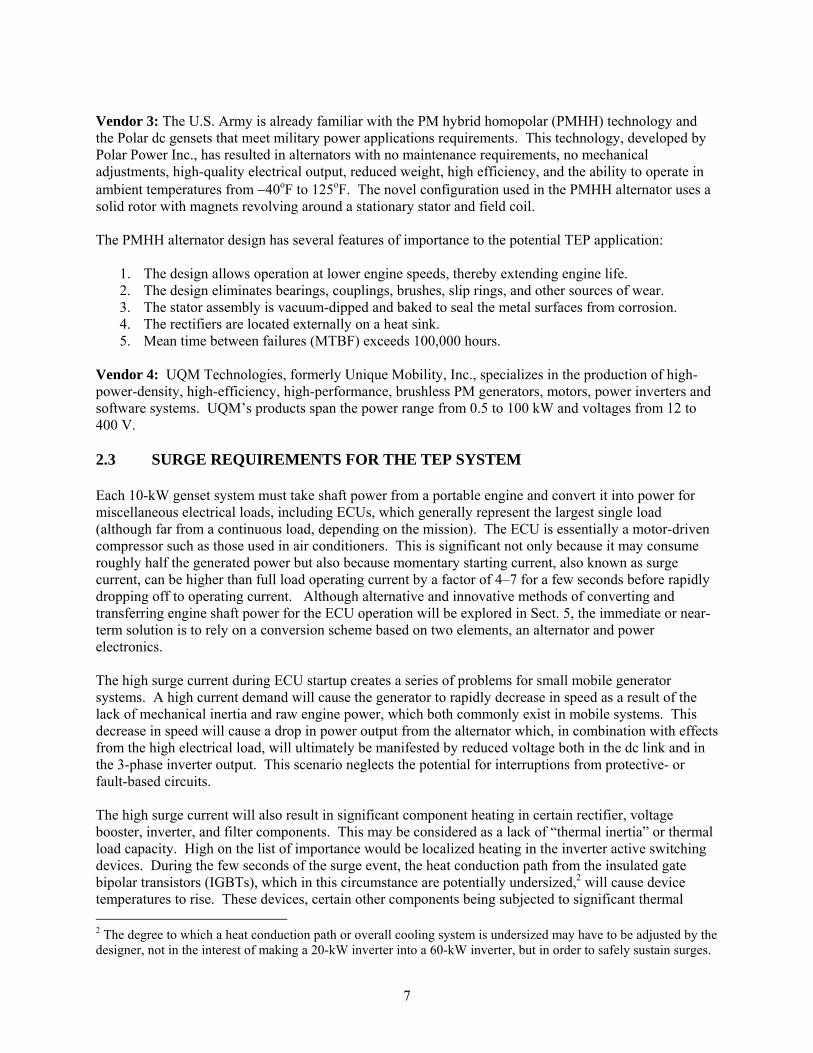
temperatures and humidity levels encountered in daytime or night conditions. Long idle periods during humid weather could cause moisture to be absorbed in certain components, degrading insulating materials. In addition, some components, such as screw-down wire terminals or cabinet surfaces, may become corroded or tarnished as a result of moisture. The microturbine industry is sensitive to these concerns. One European product, Turbec AB’s T100 microturbine, is designed for indoor installations only. Although it takes its air from an outdoor intake when the unit is operating, the power electronics would be warm, precluding condensation. Additional design work and rigorous testing over time would be required to permit outdoor installations with greater exposure to the elements. The fact that the microturbines are generally operated continuously outdoors is helpful from a reliability standpoint, since component heating tends to keep surfaces dry, and the ventilation prevents excess heat. The main concern during operating periods may be unusually hot, humid summer days; however, the use of conservative design margins and built-in thermal protection should prevent failures from occurring. The fact that the microturbine and certain other DG inverters are designed for reliable outdoor operation presents a small but significant advantage if they were adapted to meet the needs of the TEP system. This ability to operate with minimal protection from ambient conditions helps to reduce the number of uncertainties that may apply to other prospective inverter designs and provides added confidence in the inverter designers who have had to thoroughly address these issues. 3.3 MOTOR DRIVE AND MICROTURBINE CIRCUITRY AND FEATURES The basic motor drive block diagram is shown in Fig. 3.5. The diagram shows both a low-power supply for control and driver circuitry and a high-power supply that supplies power to the motor load via a power module. It is the power module and driver circuitry that are of crucial interest in the proposed TEP adaptation.
Fig. 3.5. Block diagram of an ac motor drive system without modification. Figure 3.6 shows the motor drive inverter after it is adapted to the proposed TEP system application. The high-power supply is in this case the rectified output of the alternator, and the power module drives the TEP system loads via a filter, since most loads require a sine waveform. Although the control interface and control board look unchanged, they are both essentially redesigned. The gate driver board may be only partially redesigned.
20
Fig. 3.6. Block diagram of a motor drive inverter modified for the TEP system application.
The product descriptions and specifications of motor drives reviewed in the course of this study often provided little information on the inverters but considerable detail on the broad range of control features such as sensorless vector control (VC), dynamic braking, programmable acceleration/deceleration response, and many others. Nevertheless, manufacturers will often specify that the inverter relies on IGBTs and operates with switching frequencies ranging from 2 to 12 kHz. A PWM waveform is produced, which consists of many full-on and full-off voltage pulses per cycle. The PWM waveform is fine for powering an inductive load such as a motor, but it cannot be used to directly power most other types of loads without being filtered first. For this reason, the intended TEP application will necessitate feeding the PWM waveform to a 3-phase common-mode LC filter and a 3-phase differential mode LC filter to achieve a near–sine-wave shape with less than 3% total harmonic distortion. A digitally-controlled PWM inverter is ideal for controlling motor speed because the digital controller can control the frequency of the fundamental output voltage, which in turn controls the speed of the connected motor. Although this type of variable frequency control over wide ranges loses much of its importance in the proposed application, the basic PWM inverter circuit is still highly advantageous. Of course, the digital controller and inverter can readily produce a stable 3-phase voltage at a constant 60 Hz that is required for the TEP system loads. Microturbines also use digitally-controlled PWM inverters; however, they are designed to accept a high-frequency voltage produced in a high-frequency generator. The generator speeds are generally variable over a wide range, from 50,000 to 120,000 rpm, to accommodate varying loads while maintaining high efficiency. However, as indicated in Sect. 2.4.1, the high-frequency voltage from the generator has significance only in regard to the rectifier circuit. From the dc link through the inverter and filter stages, the circuit does not change as a result of generator output frequency. Microturbines provide another advantage in that they are already equipped with matching EMI and harmonic distortion filters. In fact, microturbines produced by companies such as Bowman, Elliott, and Capstone, can be operated in a stand-alone mode to supply local loads or be connected directly to the grid. The internal circuitry ensures that the microturbine’s 3-phase power is fed into the grid synchronously. The filtering has proved effective for all manufacturers in producing an output waveform that does not produce EMI, is sinusoidal in shape, and produces lower harmonic distortion than is typically found on the local grid. Just as with the inverter circuitry, the filter circuits are located in the microturbine cabinet and are designed to operate with little protection from the outdoor environment (see Sect. 3.2).

21
3.4 DATA OBTAINED ON MOTOR DRIVE MANUFACTURERS The review of the motor drives in this section and in Appendix A will present information on the features specific to motor control applications. This level of information is provided only because it reflects the sophistication of the product and the manufacturer. The true significance of this level of detail rests on the reasonable premise that a manufacturer would not put elaborate state-of-the-art control features on an inverter that is primitive and trouble-prone. A sophisticated, well designed drive is assumed to also have a quality inverter. Table 3.1 lists several potential inverter vendors for this study. The table shows each manufacturer’s motor drive product line(s), the power level range for the motor drives or an appropriate specific model rating near 25 hp (18 kW), and the production location, if known. For some of the larger manufacturers, motor drives are one of many product lines. If a manufacturer produces, for example, 30,000 electric motors per day and many other product lines and services, the manufacturer may be generally oriented toward a low-profit-margin/high-volume approach. However, the market approach must vary by product line for overall market success. Products such as motor drives command higher prices and profit margins, and requests for modified or new products will often be considered if proposed in earnest. The Internet addresses of the motor drive manufacturers and vendors are provided in Table 3.2. In reviewing these sites, many similar drives with similar features can be seen. However, notable standouts do occur with high significance to this study. Examples evident in Appendix A are Allen-Bradley/Rockwell’s indicating a willingness to “design custom hardware or software to very specific customer requirements” and Robicon’s being amenable to producing custom drive units. The upper limits for ambient operating temperatures vary significantly and may be indicative of the degree of derating that is necessary for the different products to operate at 140oF. Price information, though sparse, showed a notably wide range that may suggest what the less costly sources of inverters may be.

22
Table 3.1. Motor drive vendors and product lines
Potential motor drive inverter vendors
Motor drive/inverter line of products
Most appropriate power level or full range
available
Location of production
ABB ACS 100–400, ACS 600, and ACS 800 Series
These series range from 0.12 to 4300 kW
AC Technology Corporation
The SCD Series 0.25–25 hp
Allen-Bradley/ Rockwell Auto.
PowerFlex 700 and 1336 Plus AC Drive
0.5–40 hp (480 Vac) 0.5–100 hp (240 Vac)
Baldor ID15 Series of ac Drives (ID15H225-EO is well sized)
25 hp (230 Vac)
USA
Bonitron, Inc. Drive accessories Unknown USA Cleveland Motion Controls
ACtionMaster series drives Fractional to 500 hp
Control Techniques (Emerson Industrial Automation)
Unidrive SP Solutions Platform Most applicable range: 1 to 40 hp
(380–460 Vac)
Eaton, Cutler-Hammer SV9000 (various voltages), Responder 9000 Series
0.25–125 hp (230 Vac) 0.75–1000 hp (380 Vac)
General Electric/Fuji AF-300 CT and AF-300 VT 0.25–125 hp (230 Vac) 0.5450 hp (460 Vac)
Japan
International Rectifier Produces electronic modules used in inverters.
-- --
KEBCO Power Transmission
KEBCO COMBIVERT 0.5–400 hp
Magnetek/Yaskawa GPD 515/G5 General Purpose Drives
0.75–1750 hp (208/230/460/600 V)
Japan
Omron IDM Controls (Yaskawa)
P5+ Series (general purpose) G5+ (multi-purpose)
18.5–160 kW for the P5+ series
Japan
Reliance/Rockwell Automation
SP500 series, SP600 series, and GV3000/SE
20 hp (SP500/SP600) 25 hp (GV3000/SE)
North America
Robicon 454GT series and the ID series
3–800 hp (454GT) 2–100 hp (ID)
Siemens Simovert Masterdrives TVC 2.2–5000 kW Germany Square D Econo-flex and lines of
ALTIVAR ac drives 0.75–400 hp; 25 hp models available
US Electric Motors Subsidiary of Emerson -- -- US Drives Phoenix DX and EX series of
AC Vector drives 3–3500 hp USA

23
Table 3.2. Motor drive vendors and internet sites
Potential motor drive inverter vendors
Internet address - urls
ABB http://www.abb-drives.com/ AC Technology Corp. http://www.actechdrives.com/ Allen-Bradley http://www.ab.com/ Baldor http://www.baldor.com/products/default.asp Bonitron, Inc. http://www.bonitron.com/products.htm Cleveland Motion Controls http://www.cmccontrols.com/ Control Techniques http://www.ctdrives.com/ Eaton, Cutler-Hammer www.ch.cutler-hammer.com Emerson http://www.gotoemerson.com/index.jsp Fuji http://www.fujielectric.co.jp/eng/company/group/contents.html General Electric http://www.geindustrial.com/cwc/home International Rectifier http://www.irf.com/ KEBCO Power Trans. http://www.kebco.com/ Magnetek/Yaskawa http://www.magnetekdrives.com/products/default.asp Omron IDM Controls (Yaskawa)
http://www.idmcontrols.com/
Reliance http://www.reliance.com/prodserv/products.htm Robicon http://www.robicon.com/products/acdrives/index.html Siemens http://www.sea.siemens.com/drives/default.html
http://www.ad.siemens.de/meta/html_76/ant03.htm Square D http://www.squared.com/ US Electric Motors See parent company – Emerson US Drives http://www.usdrivesinc.com/products.htm
Appendix A lists, for many of the same manufacturers, details of their motor drive product lines. The appendix summarizes many features of the motor drives and describes some individual models in the 25-hp range that may be considered adaptable for the TEP application. That is, the market-proven inverter circuit could be “lifted” from the motor drive product and designed into a 10-kW power converter product with necessary modifications/redesign: (1) fault detection, (2) fault protection over-ride, (3) control circuitry simplification, (4) heat sinking/ventilation in the inverter cooling system, (5) shock/impact resistance, and (6) the addition of filtering if contracted to the inverter manufacturer. In many cases, the inverter circuit will be able to accept the voltage supplied to it by the alternator6 and produce the required output with little or no modification. This is due to the fact that the inverter circuits have already been designed to accommodate wide ranges of voltages for compatibility with many industrial applications around the world. 3.5 DATA OBTAINED ON DISTRIBUTED ENERGY RESOURCES INVERTER
MANUFACTURERS This section presents basic information relating to inverter manufacturers whose products are either quite general in design and/or are suited for microturbines and other DER applications in the size category from 20 to 100 kW. It becomes very evident just how new the microturbine industry is when one considers all of the manufacturers that are either marketing their products as of the last few years or are taking orders
6 The inverter manufacturer is expected to have a key role in selecting the appropriate alternator.

24
for soon-to-be introduced products. Even the “oldest” manufacturers are just beginning to see their products arrive at the first major overhaul point. At best, the reliability calculations for microturbines and the associated inverters are now becoming less theoretical and more based on actual in-service data. Table 3.3 provides a list of all known inverter manufacturers for DG, primarily microturbines, with the exception of one special-case developer discussed separately in Sect. 3.9. The table indicates the relevant product or development activity for each manufacturer, whether their inverters are an in-house design and production effort, and additional notes or comments. The table indicates that certain manufacturers do not presently produce inverters for use in microturbines or DER in general. For instance, Elliot Energy Systems purchases all of the inverters used in its microturbines from Bowman Power Systems. Although the parent company of Elliott Energy Systems, Ebara Corporation of Japan, is reportedly becoming a new supplier of inverters to Elliott, it is too early to report on how these inverters might differ from those supplied by Bowman.
Table 3.3. Power converter and/or DG manufacturers whose products are in production and available on the market
Manufacturer
Product or development activity Producer of invertersa
Notes
Ballard EcostarTM inverters from 10 kW to 1 MW
For general DER
applications
Fuel cells are Ballard’s main product line
Bowman Power Systems
TurbogenTM family of microturbines ranging from 25 kWe to 80 kWe
Yes Supplies inverters to Elliot Energy Systems, Inc.
Capstone Turbine Corp.
30-kW and 60-kW microturbines Yes Integral module; DOE-AMPb participant
Elliott Energy Systems, Inc. — Ebara Corp. (Japan)
35-kW, 60-kW, and 80-kW microturbines, products have used Bowman inverters; however, the Ebara Corp. is an emerging supplier
No Supplies mechanical microturbine systems to Bowman Power Systems
Exeltech Inc. MX series general use inverter line, lightweight, sine-wave output, up to 60 kW. New GX series by 2004.
Yes – general applications
Unique modular system that is compact and expandable
Solectria Corporation
Model DMOC445 add DMGI445 produce 38 kW, 3-phase
Yes Sells inverters for use in electric vehicles and DG applications
Turbec AB (owned by ABB add Volvo)
Model T100 is a 105-kW microturbine marketed almost exclusively to Europe
Yes Modest sales in U.S.; not fully included in the present study
Xantrex A wide range of inverters are available for any type of generator.
For general DER
applications
No present microturbine applications
a Indicates whether the inverters are an in-house product. b DOE-AMP = Department of Energy’s Advanced Microturbine Program. Not all participants are involved in development of power electronics; therefore, not all are listed.
Turbec produces a Model T100 105-kW combined heat and power microturbine that uses a dc link power converter topology to convert the generator’s high frequency output to useful power. Turbec markets primarily to Europe with distributors in Italy, Switzerland, France, the United Kingdom, Ireland, Denmark, and Germany; therefore, this study’s consideration of Model T100 is somewhat limited. However, several unique features and characteristics that merit consideration are briefly summarized in Appendix B.

25
Table 3.3 also lists some manufacturers, such as Ballard and Xantrex, who market versatile power converters designed for use with renewable wind and solar energy generators and other types of DER applications. These applications are distinct primarily because they need not accept a high-frequency output from generators such as is used in microturbines. Although Ballard and Xantrex have also developed products capable of converting power from high-speed microturbine generators, they are not currently marketed. Exeltech, Inc., produces a truly general purpose inverter line (MX series) that has several features potentially of high interest for TEP applications such as modularity, light weight, and sine-wave output. However, Exeltech’s 1-kW MX modules are smaller than desirable. Table 3.4 provides the Internet addresses for the full list of vendors presented in this section.
Table 3.4. Manufacturers and internet urls
Manufacturer
Internet url
Ballard http://www.ballard.com/ Bowman Power Systems http://www.bowmanpower.com/ Capstone Turbine Corp. http://www.microturbine.com/ Elliott Energy Systems, Inc./ Ebara Corp.
http://www.elliott-turbo.com/new/products_microturbines.html
Exeltech Inc. http://www.exeltech.com/ex_root/data.htm Turbec AB (owned by ABB add Volvo)
http://www.turbec.com/
Xantrex http://www.xantrex.com/Products/index.asp 3.6 SURVEY OF MOTOR DRIVE MANUFACTURERS This assessment of the commercial inverter industry entailed a limited survey that was prepared and sent to more than 15 motor drive manufacturers and/or inverter manufacturers in order to
• Determine their interest in adapting their technology to the TEP application • Determine the extent of their market reach • Assess the reliability of their motor drives
The survey was limited in that follow-up was not pursued routinely and repeatedly with non-responders. This was for three reasons: (1) the main interest rested in those companies who were genuinely interested in this potential non-commercial application, (2) responses from a limited number of companies would be adequate to establish the potential reliability7 of these inverters, and (3) the time spent pursuing non-responders could be better spent in other project activities. Nevertheless, a second inquiry was sent to a portion of the companies in the list and, in fairness to the earlier responders, responses made to the second inquiry are noted as such. A copy of the survey form is provided in the text box on the next page. The survey form was sent with a letter indicating the following:
“This survey is being conducted for the U.S. Army to assist them in obtaining a power electronics interface between their portable generators (i.e., alternators) and their 3-phase loads. We are very
7 In fact, this reliability can be assumed without the survey. If these products had significant reliability problems in, for example, the inverters, it would be quite well known throughout industry.

26
interested in considering commercially proven motor drives; these are of interest only because of the inverter circuits they contain. The immediate aim of this survey is to provide the Army with information that clearly shows that inverters are sold commercially in the power class of interest that are both robust and reliable. This is important in light of the Army's poor experience with inverters that they have tested to date (i.e., 3 tested and 3 failed). Ultimately, a significant number of these units will be produced, subsequent to Army testing and acceptance. (Please note that the Army intends for the PWM waveform to pass through a 3-phase common-mode LC filter and a 3-phase differential mode LC filter to achieve a near sine-wave shape with less than 3% total harmonic distortion).”
The survey form was designed to obtain a brief indication from the company of (1) general interest in developing a specific non-commercial product, (2) sizing of the inverter, (3) market penetration of their motor drives, (4) reliability of their products, (5) physical characteristics, and (6) price. Items such as size and price are, of course, very rough initial estimates. The primary value of the survey is found in the responses to the first four items and the very fact that the company completed and returned the survey.

27
Inverter Survey (US Army/ORNL) February-March 2003 Oak Ridge National LaboratoryCompany: Contact: Phone/e-mail:
Direct survey questions to: Robert Staunton, [email protected], (865) 946-1351
The Army has a potential inverter application that takes alternator power1 and converts it to 120V/208V, 3-phase power at 10kW (with a possible additional requirement for 28 Vdc). A significant number of units would be required. Special military requirements would have to be met such as drop tests, limited weight, and operation at up to 140oF ambient. Questions for Vendors of Inverters/ASDs 1. Does your company have a potential interest in accommodating a non-commercial
(Army) application based on your inverter or adjustable speed drive (ASD) product line?
2. In light of the 140oF ambient temperature requirement, we at ORNL envision taking
a commercially proven 15 to 20 kW inverter (e.g., motor drive) and adapting it for this 10 kW application. Does that sound reasonable?
3. Approximately how many inverters/ASDs does your company sell in the 15 to
20 kW power class (alternatively, provide some other indication of sales)? 4. Can you provide us with reliability information on your line(s) of inverters? 5. Size and weight of inverters in the 15 to 20 kW power class if not listed on web site? 6. Cost of inverters the 15 to 20 kW power class if not listed on web site?
Please return completed form to: Robert Staunton, [email protected] ---------------------------- 1 The alternator model is fluid at present. Ideally, it would supply about 200 Vdc. A 3-phase power is another possibility. The inverter supplier will most likely be able to influence this specification

28
In response to the survey’s request for information, the following responses were received: Vendor 1: US Drives Contact: Richard L. Torbenson Phone/e-mail: [email protected]
1. Expression of interest: US Drives does have a standard ASD Product but we are interested in special applications where moderate unit volume is possible.
2. Inverter sizing — 15–20 kW is adequate based on 140oF ambient: Yes. Our standard ASD is
rated for 122oF (50oC) operation without derate.
3. Sales quantity in power class of interest: Approximately 200 to 300 units per year.
4. Reliability of product line: Based on warranty data, we see far less than a 1% failure rate during our 3-year warranty period.
5. Inverter size and weight in power class of interest: 9.2 x 9.0 x 10.9 in. (H x W x D),
30 pounds.
6. Cost of inverter in power class of interest: Approximate cost $1000 to $1400. Vendor 2: Omron IDM Controls Contact: Charles Manning Phone/e-mail: 713-849-1900/[email protected]
1. Expression of interest: Omron IDM Controls is interested in adapting a circuit for the U.S. Army
2. Inverter sizing — 15–20 kW is adequate based on 140oF ambient: Possibly. The inverter is
rated for 104ºF, NEMA 1, and 113ºF, open chassis. There are temperature derating factors that can be applied. However, the life of the inverter may be shortened if operated at high temperatures. Based upon Omron plots, you can expect the current derating factor to be approximately 75 to 85% at 140ºF.
3. Sales quantity in power class of interest:
485 units in the last 12 months (230 and 460 Vac, 15–22 kW, CT and VT). 155 units in the last 12 months (230 Vac, 15–22 kW, CT and VT). Omron’s product ratings in the range of interest are 15 kW, 18 kW, and 22 kW.
4. Reliability of product line:
Published MTBF ratings are 28 years or more in typical specifications. Calculated MTBF from 2001 is much higher: 264.86 years for G5+ product and 460.30 years for P5+ (most up-to-date information). Omron expects that the number of random failures per year will equal the number of inverters installed / MTBF.

29
5. Inverter size and weight in power class of interest: In the table, all of the HP and full load amps (FLA) values apply to constant torque operation.
Model # HP FLA Dimensions (in.) Weight (lb.) G5U-2015-N1 20 64 15.75x9.84x8.86 24 G5U-2018-N1 25-30 80 24.02x12.99x11.22 71 G5U-2022-N1 30 96 26.57x12.99x11.22 71 P5U-2015-N1 20/25 64 15.75x9.84x8.86 24 P5U-2018-N1 20/25 64 24.02x12.99x11.22 71 P5U-2022-N1 30 83 26.57x12.99x11.22 71
6. Cost of inverter in power class of interest:
G5U-2015-N1 — $2908 P5U-2015-N1 — $2131 G5U-2018-N1 — $4180 P5U-2018-N1 — $2423 G5U-2022-N1 — $4573 P5U-2022-N1 — $3144 All of the above are NET prices
Additional comment: We would prefer a dc supply of closer to 220–230Vdc+, or 3-phase ac if possible. The under-voltage trip point for our inverters will be approximately 190 Vdc. 208Vac will not be a problem, but we do not currently have a 120 Vac product.
Vendor 3: Baldor-Atlanta Contact: David Woodson Phone/e-mail: 770-772-7000, ext. 30/[email protected]
1. Expression of interest: Baldor is a designer and manufacturer of industrial motor controls. All of our ac inverter designs are manufactured in the United States at various locations. As a designer and manufacturer of ac inverters, we create custom variations of our standard product offerings on a regular basis. We would certainly be willing to entertain any product requests if submitted.
2. Inverter sizing — 15–20 kW is adequate based on 140oF ambient: In most cases, de-rating
the control output is a good step in applying power electronics to a high-ambient-temperature application. The ambient suggested above begins to reach the inherent temperature limits of the controlling electronics, namely the integrated circuits. Care would need to be exercised to cool the control IC’s to an acceptable level to ensure reasonable product life.
3. Sales quantity in power class of interest: We have been designing and manufacturing power
electronics in the United States for over 20 years. Depending on the economic conditions, we typically produce 800 to 1000 pieces a year in the stated power range.
4. Reliability of product line: For this power range, total returns are in the range of 2.5–3% per
year. The warrantable failure rates are typically lower.
5. Inverter size and weight in power class of interest: The physical sizes vary by power rating. We split between two sizes in the listed range: 15.4 in. H × 10in. W × 7.1 in. D @ 30 lb and 16.9 in. H × 10.5 in. W × 9.6 in. D @ 60 lbs
6. Cost of inverter in power class of interest: List prices for stock industrial products in the stated
power range are $3798.00 to $5085.00.

30
These manufacturers responded to ORNL’s request for information after a single contact, in some cases other contacts may have been made only to answer specific questions. This is considered to be an important indication of both the company’s responsiveness and interest in providing a product specifically for the TEP application. The vendor Bonitron responded without a solicitation for information from ORNL. One of the company’s inverter vendor partners forwarded ORNL’s information request to it. Bonitron manufactures products related to line generation, resistive braking, braking control, power dip ride through, motion control, drive accessories, etc. It is not clear from information on the company’s website whether it presently produces complete inverter systems. Vendor 4: Bonitron, Inc., 521 Fairground Ct., Nashville, TN 37211 Contact: Keith Benson Phone/e-mail: 615-244-2825 office, [email protected]
1. Expression of interest: Bonitron manufactures custom ac-drive-related power modules. For many years Bonitron has been a primary source of ac drive components for the synthetic fiber drive industry. For the past 15 years, Bonitron’s primary customers have been ABB, AB, Reliance and Siemens drives divisions. For these manufacturers, we build inverter modules, dc-to-dc converters, and control modules for those applications that have specifications not met by their standard products. We have recently been working closely with RA on applications involving electric drives for military vehicles.
2. Inverter sizing — 15–20 kW is adequate based on 140oF ambient: Bonitron would provide a
10-kW inverter designed for the extended temperature. Typically, commercial components with good sourcing can be used if heat sinks and thermal management systems are properly selected.
3. Sales quantity in power class of interest: Bonitron typically designs and manufactures for
applications involving requirements for 25 to 5000 units. Bonitron has about 40 designs of power modules rated in the 15- to 20-kW range. The company has built several inverter modules that are used with electrical vehicles where input power is a dc battery bus that varies between 200 and 400 Vdc depending on whether the vehicle is accelerating or braking.
4. Reliability of product line: Bonitron can provide a list of its major customers and access to its
service records showing extremely high reliability. The primary end users of Bonitron products are semiconductor fabrication facilities and synthetic fiber plants where down time is typically estimated at $100K to $500K per event. Therefore, reliability is a critical factor in all designs.
5. Inverter size and weight in power class of interest: These specifications can vary
considerably, depending on incoming line or dc bus regulation requirements, switching or carrier frequency specifications, and primarily thermal management design (i.e., convection, fan cooled or liquid cooled heat sinks).
6. Cost of inverter in power class of interest: Depending on specifications and quantities,
modules in this range cost between $1500 and $3750.

31
The following manufacturers responded only after a second inquiry or several weeks late: Vendor 5: Square D Company Contact: Larry Stanley Phone/e-mail: 615-844-8793 office, 615-604-0329 cell, [email protected]
1. Expression of interest: The above contact is the variable frequency support engineer within Square D Co for Knoxville, Chattanooga, and Nashville. Square D would be interested in discussing any opportunity regarding a specific drive application. The contact would be more than glad to assist you at your facility or at our office.
2. Inverter sizing — 15–20 kW is adequate based on 140oF ambient: Yes, that is reasonable.
3. Sales quantity in power class of interest: 15,000+ annually
4. Reliability of product line: We can provide this information.
5. Inverter size and weight in power class of interest:
15KW ATV58HD23M3 Rated 60 amps output cont., 230 Vac, 3-phase 9.45 in. W × 21.65 in. H × 11.14 in. D, 75 lbs 18.5KW ATV58HD28M2 Rated 75 amps output cont., 230 Vac, 3-phase 13.78 in. W × 25.59 in. H × 11.97 in. D, 126 lbs 22KW ATV58HD33M2 Rated 88 amps output cont., 230 Vac, 3-phase 13.78 in. W × 25.59 in. H × 11.97 in. D, 126 lbs
6. Cost of inverter in power class of interest: 15 kW $2200.00 net, 18.5 kW $2300.00 net,
22 kW $2645.00 Vendor 6: KEBCO, Inc Contact: Steve Hibbard (commercial), Brad Wilkinson (technical) Phone/e-mail: 651-675-2809, 651-675-2825
1. Expression of interest: Yes, we have an interest in accommodating a non-commercial (Army) application.
2. Inverter sizing — 15–20 kW is adequate based on 140oF ambient: Some components,
specifically in the control part and switch mode power supplies, would need to be evaluated for such operation, because the heating of these components is not proportional to the actual power flow through the drive. We do burn in all our standard drives at 140°F for 7 hours so we know the units will function.
3. Sales quantity in power class of interest: KEBCO manufactures approximately 150,000
inverters annually in the power range from 0.37 to 750 kW, of which approximately 10,000 are in the range of 15 and 20 kW.

32
Fig. 3.7. KEBCO motor drive.
4. Reliability of product line: We have been producing inverters since 1986, our newest series of inverters (Product F5) has an MTBF = 373 years or 3268618 hours.8 This series began in year 2000. Year: 2000 = 5.78% (initial pre-release of 294 total units only), 2001 = 1.99% 2002 = 1.03 % 2003 (ytd) = 0.024%
5. Inverter size and weight in power class of interest: Depends on final design. Generally G-
housing is 6.75 × 13.5 × 10 in. (see general catalog).
6. Cost of inverter in power class of interest: 15-kW units sold on average in 2002 for $3272 USD. Pending final design features, control card requirements, and quantity make the price negotiable to a point lower than the average cost.
8 Upon a review of KEBCO’s calculations, it was found that it was incorrectly assumed that all 25,267 units were installed and in operation during the entire 3.5-year period since the F5 was introduced into the market. ORNL reviewed F5 data as of mid-year 2003. Based on this review, if one assumes that yearly production totals are not actually installed and in operation until the end of the third quarter of each year, or the end of the half-year period for 2003, the MTBF for the 3.5 year period decreases to about 70 years. This is still a theoretical calculation that does not take into account wear-out effects over time. For instance, if most cooling fans were to fail from wear out in the 20–30 year time frame, the 70-year MTBF would have little meaning. Hence, MTBF is bounded by wear-out which is an unknown.

33
3.7 SURVEY OF DISTRIBUTED ENERGY RESOURCES INVERTER MANUFACTURERS
Based on the information presented in Sect. 3.5, the final list of companies in the U.S. market who are presently producing and marketing inverters suitable for general applications and DG, not just microturbines, is quite small. It includes the following:
• Ballard (provided inverters for Honeywell microturbines in 1998) • Bowman Power Systems • Capstone Turbine Corporation • Exeltech, Inc. (modular inverters for general applications) • Solectria Corporation (inverters for transportation and DG) • Xantrex (no presently marketed microturbine application)
Information was recently obtained in a separate study performed for DOE’s Microturbine Program manager. Appendix B provides excerpts of information obtained from the microturbine inverter manufacturers that was documented in a report [12] issued to DOE in March 2003. Much of the information presented in the Appendix is of a technical nature dealing with topics such as active switching component types, thermal ratings, circuit topologies, and switching frequency. In addition to the information in Appendix B, requests for information were sent to the DG inverter manufacturers consistent with the inquiries made to motor drive manufacturers (see Sect. 3.6). The introduction letter and inquiry form were slightly reworded since a somewhat different industry was being addressed. The results are provided below. Vendor 1: Xantrex Contact: Rob Heckenast Phone/e-mail: 604 415-4679, [email protected]
1. Expression of interest: Xantrex is definitely interested in specialized inverter development for volume sales based on our proven inverter topology. Xantrex has recently used this topology in developing the inverter for the >1MW GE wind turbine project. We have a photovoltaic (PV) series inverter that accepts 330–600 Vdc input and inverts the power to produce very pure 3-phase 120/208, which can be transformed up to 480 Vac as needed. These commercial models can switch between modes and are lightweight and wall mountable.
2. Inverter sizing — 15–20 kW is adequate based on 140oF ambient: Our PV15208 should have
sufficient margin after derating to provide 10 kW up to 140oF. Current PV15208 design provides 15 kW up to 122oF with 240 W/oF derating above 122oF ambient. PV series achieves 95% peak efficiency using IGBT switching technology. See website for data sheet or contact Xantrex directly (see above).
3. Sales quantity in power class of interest: Approximately 500 inverters have been sold in the
10–20 kW power class since introduction in 1999. Total volume is far higher for our complete PV line, which ranges in power from 5 to 225 kW.
4. Reliability of product line: MTBF figures are being developed but not yet available. The PV
series has a strong reputation for reliability in the commercial PV/grid-tie inverter industry. Contact Xantrex for installation references.

34
5. Inverter size and weight in power class of interest: The PV15208 current design is 160 lbs
(73kg). Wall-mounted enclosure dimensions are 28 in. (H) × 24 in. (W) × 15 in. (D) (isolation transformer if required is separate/external).
6. Cost of inverter in power class of interest: PV15208 — MSRP is US $12,220; cost of variant
is dependant on requirement specifications. Cost of inverter could be very close to existing production model if alternator input is within present input voltage range of 330–600V.
Vendor 2: Capstone Turbine Corporation Contact: Joel Wacknov Phone/e-mail: (818) 734-5549, [email protected]
1. Expression of interest: Yes, we have an interest in accommodating a non-commercial (Army) application.
2. Inverter sizing — 15–20 kW is adequate based on 140oF ambient: Capstone inverters are
rated for 50oC ambient operation (123oF) and have been tested to 60oC (140oF). It makes sense to de-rate the power at higher temperatures. Capstone’s 30-kW, digital power controller (DPC) would be very well suited for this application. It has two inverters in one enclosure—one for the generator and one for the load.
3. Sales quantity in power class of interest: Capstone has shipped over 4,000 inverters in the 30
kW class and 1,000 inverters in the 60 kW class. Each Capstone Microturbine has two inverters – one connected to the generator and one connected to the load.
4. Reliability of product line: Capstone has accumulated over 2 million hours of real-world
inverter operating experience. Capstone’s inverters are designed for harsh, outdoor environments.
5. Inverter size and weight in power class of interest: Capstone’s 30 kW DPC is approximately
33” X 12” X 18” and weighs 150 lbs. This unit contains two 30 kW inverters.
6. Cost of inverter in power class of interest: The price range of Capstone inverters is approximately $350/kW in this power class, at low volume.
Vendor 3: Solectria Corporation Contact: Mark Federle Phone/e-mail: (781) 932-7455, [email protected]
1. Expression of interest: Yes, Solectria is interested in the potential application. The company currently has a 10-kW, 3-phase inverter, similar to that shown in Fig. 3.7, which is being applied to both commercial and military applications. Furthermore, Solectria has developed a product for military applications that requires 28 and 270 Vdc and has filtering systems that allow for 50, 60 and 400 Hz output. Solectria has designed the product to meet stringent mil-standards. Finally, Solectria has developed multiple applications for the military that are vehicle mounted and/or integrated and, as a result, has extensive experience in that environment.

35
Fig. 3.8. Solectria inverter.
2. Inverter sizing — 15–20 kW is adequate based on 140oF ambient: Agreed — also, to the extent liquid cooling is an option, greater efficiencies can be had. Solectria has developed a 15-kW auxiliary power distribution system for TACOM that may meet the requirements.
3. Sales quantity in power class of interest: Solectria is on track to do $10 million in sales in
FY 2003. Solectria is a developer of advanced power electronics technology for both vehicle and DG applications. We currently sell hundreds of inverters in the range specified and have systems developed for existing customers that could drive volumes up into the thousands of units per year.
4. Reliability of product line: Solectria has limited MTBF data; however, we have been in
business for 14 years and have close to 4000 systems fielded primarily in vehicle applications that have withstood the test of time in every conceivable environment and exposed to every conceivable environmental condition (e.g., extreme heat, cold, rain, snow, vibration).
5. Inverter size and weight in power class of interest: Approximately 25 lbs.
6. Cost of inverter in power class of interest: Single unit pricing is approximately $2500.
Vendor 4: Exeltech Contact: Kevin Parsons Phone/e-mail: [email protected]
1. Expression of interest: Yes.
2. Inverter sizing — 15–20 kW is adequate based on 140oF ambient: Yes this is reasonable. However, depending upon the extent of ruggedization required, further thermal-related performance degradations could be experienced.
3. Sales quantity in power class of interest: 25% of sales of our MX series (see Fig. 3.9) modular,
expandable inverters are in the 10 kW and up range.9 Our reputation in the market place is for mission-critical and/or revenue-generating applications.
9 From further inquires, ORNL concluded that, for the power range of interest, the production was 200 to 280 units per year. Following yet additional inquiries, it became clear that several 1-kW modules would have to be used in parallel for the proposed application. The new, higher-powered GX series is only in the bench-testing phase.

36
Fig. 3.9. Exeltech inverter.
4. Reliability of product line: All repairs on product are performed at the factory. Data extrapolated from number of units repaired vs. number of units shipped indicates an MTBF in excess of 20 years.
5. Inverter size and weight in power class of interest: Estimated weight is 160 pounds. Size:
23 in. W × 23 in. H × 15 in. D. Could be about half of that weight and size if PM generator can provide required input voltage (i.e., 200 Vdc).
6. Cost of inverter in power class of interest: Currently $15K–$20K. Target of $7K–$10K for
proper PM generator voltage unit (i.e., 200 Vdc).10 3.8 ASSESSMENT AND RANKING OF INVERTER MANUFACTURERS Reliability was a significant issue for motor drive inverters following their introduction in the late 1970s. Not only did the power electronics experience excessive failures in products from several manufacturers, but also capacitors and other power components were problematic in some instances. Failures were often comparable to explosions — cabinet doors may have blown off and shrapnel damage been present throughout the motor control room [13]. Since that time, aggressive research produced technical solutions and component refinements that have resulted in a generally thriving industry with very reliable products. The reliability specifications of motor drives advertised today are typically expressed as MTBF in a range from 10 to 30 years, depending on manufacturers and the power class of the motor drive. Those manufacturers whose operation data indicate high MTBFs should use caution in both the calculation and interpretation of this measure of reliable performance. As indicated in a footnote for Vendor 6 in Sect. 3.6, the MTBF was lower than the manufacturer indicated and, in practical terms, was bounded by the wear-out phase. In addition, considerable operating time, number of units in operation, and a significant number of failures are all necessary in order to identify a failure rate or MTBF with a reasonable level of confidence. Similarly, inverters used in the microturbine and DER industries have seen tremendous improvements in reliability, but in a more compressed timeframe. DER systems introduced in the last 10 years experienced, in many cases, reliability problems within electrical and mechanical subassemblies; however, the industry pursued solutions with great vigor since doing so was a matter of their survival in the emerging industry. Technical fixes were rushed out to support field repairs as quickly as they were
10 Clearly, Exeltech would be interested in exploring the possibility of eliminating costly active rectification circuitry through the careful selection of the alternator.

37
available. The manufacturers were repairing not only customer units but their company reputations as well. With many of the growing pains now behind them, it appears that microturbine manufacturers have successfully maintained their respect in the market. Prospective customers believe that they can make purchases based purely on economics such as life cycle cost, and power electronics reliability is not an important issue. This is not to say that these manufacturers are able to provide definitive failure rate specifications to prospective customers, since they generally have far less operations and failure data than motor drive manufacturers. The confidence that their customers have in them is based primarily on reputation. Based on this assessment of the primary inverter industries, this section will review the manufacturers based not only on reliability but on several other factors as well. Since nearly 30 companies have been reviewed in Sects. 3.4 and 3.5 and only 3 to 6 will be selected for product development, it seems reasonable to initially reduce the number of companies to those who showed enough interest to respond to ORNL’s requests for information and a couple of additional companies that seemed to stand out based on a review of information provided in Appendices A and B. This first cut results in the companies listed in Table 3.5. The companies shown in italics are from the DER or general inverter field, and the others are motor drive suppliers. The table indicates whether the company is a respondent, what positive highlights are known about the company, whether the company has experience with designing inverters for operation in harsh environments, their success in the market (i.e., number of units sold), and a rough indication of cost.
As indicated under the highlights column, reliability data were not available from any of the non-motor-drive manufacturers except Exeltech. This is not unexpected, based on the discussion. Even the large motor drive vendors, with two exceptions, relied on product returns/service data or had no reliability data on hand to use in their response. Omron IDM Controls and KEBCO were the two motor drive companies with MTBF data, and the MTBFs were very positive.

38
Table 3.5. Summary of initial best prospects for inverter suppliers for proposed TEP systems (including motor drive and DER vendors)
Inverter vendors of high interest
Survey respondent
Positive highlights pertaining to prospective company (reliability data provided where available)
Moist/hot air
tolerance
Production in target power
class
Rough cost est. ($1000)
Allen-Bradley/ Rockwell Auto.
No Company markets a lower-power product line that is consistent with the prospective product; company advertises an interest in preparing custom designs
-- Unknown Unknown
Baldor Yes1 Large domestic manufacturer with low returns (both in-warranty and beyond) of 2.5 to 3% per year
-- 900/year 3.8–5.1
Bonitron, Inc. Yes (unsolicited)
Much experience in supplying power modules to major ac drive manufacturers. Provides specialized, high-reliability circuits for critical applications (see text)
-- Depends on circuit or module
1.5–3.8
Capstone Turbine Corp.
Yes1 This company has tested its 30-kW inverter in exposures up to 140oF and would adapt it for TEP application
Yes 4000 (total production)
0.4
Exeltech Inc. Yes1 MTBF >20 years. Unique modular, expandable design inverter system for general applications. Regulated sinusoidal output voltage with less than 2% distortion. A somewhat “forced application” since several 1 kW modules are required per phase.
-- 200–280 7–10 (up to 20 —
see text)
KEBCO, Inc. Yes The MTBF of the new F5 series extends to wear-out. Burn-in tests for its inverters are conducted at 140oF
-- 10,000/year 3.3 or less
Omron IDM Controls/Yaskawa
Yes1 MTBF = 28 years for “typical specifications.” Their survey response posed specific considerations for alternator specs
-- 640/year 2.1–4.5
Robicon No Company advertises an interest in designing custom drive units -- Unknown Unknown Solectria Corporation
Yes1 Has built inverters to military standards. Inverter line is generally for dc-input and with unregulated output
Yes 1000s in FY 2003
2.5
Square D Yes (local sales rep.)
A very large, experienced motor drive manufacturer -- 15,000/year 2.2–2.6
US Drives Yes1 Records indicate good reliability (far less than 1% returns during 3-year warranty period)
-- 200-300/year 1–1.4
Xantrex Yes1 Provided confident and detailed information on meeting the needs of TEP system
Yes 500 sold in 1999
12.2
1Company responded in a reasonable time following a single request for information.

39
Bonitron is unique in several respects. It sells many different types of drive components to major companies, such as DuPont, often to meet special requirements, whether they are new designs or circuits to meet critical needs not fully met by standard products in the motor drive industry. Many of the option modules the company produces are regeneration modules and power-dip or loss-ride-through modules. This is not to say that Bonitron does not have inverter products of interest to the TEP program. The company states that it has about 40 designs of power modules in the power range of interest. However, it appears that the design of a fully integrated inverter system for the TEP application, with all supporting circuits, such as controller and gate driver, is not a routine design exercise for Bonitron. Sales data for the manufacturers in the power class of interest varied widely from lows of about 200 per year to highs of about 15,000 per year. It is suspected that Square D’s high sales figure of 15,000 may not have been limited to the specified power class range, such as implied in the brief responses from Square D were provided by a local sales representative. The rough estimates of cost ranged considerably, from a low of $1,200/inverter to a high of $20,000/inverter. Of course, this early survey did not ask for a formal estimate or even an estimate with a list of assumptions or specifications. Nevertheless, the results were more useful than expected in light of the broad spread. If nothing else, the response will be useful in distinguishing the companies that provided estimates at or near the two extremes. The greatest confidence can be placed in the high estimates and less confidence in low estimates since companies may simply be seeking to establish an early advantage. ORNL believes that this assessment of manufacturers can be made most useful to CECOM by using a semi-quantitative translation or mapping into an actual ranking of manufacturers. This approach will aid in making the selection of manufacturers for product testing as objective as possible. A scoring methodology was developed based on the responsiveness of the manufacturers, supplied technical information, supplied reliability information, the demonstrated ability of products of each manufacturer to operate in harsh environments, relative production levels, and cost. A score was assigned to each manufacturer based on the following:
• Survey respondent [0 to 5]: A respondent based on a single request received 5 points, respondents based on second request received 3 points, and non-respondents received 0.
• Positive highlights [0 to 10]: An automatic 3 points was awarded for offering some indication of reliability; the remaining 7 points were assigned based primarily on design and packaging experience closely related to the needs of the TEP program. Overall quality of response and/or marketing literature is also a strong consideration in the scoring.
• Environmental [0, 3]: Three points were assigned for applicable design experience, otherwise 0. • Production level [0, 3]: Three points were assigned to high sales over a period of years and 0
assigned to the lowest sales. Unknown production for well known companies = 1 point. A log scale is used, since sales beyond several hundred a year lose significance. For the same reason, the production numbers are truncated at 3000 (this upper limit affected only 1 manufacturer).
• Cost [0, 10]: Points were assigned in inverse proportion to cost estimates. No scoring above 8 is assigned for very low cost estimates without some justification offered by the company. No estimates = one point less than the score for an average estimate.11
11 Although this last rule may seem arbitrary, it was applied to only two companies that, in the final scoring, ranked lowest. Thus, there is no danger of being too favorable to companies lacking a cost estimate.

40
The relative weight given to each category, as reflected by the number of possible points, was reviewed by CECOM RDEC and is consistent with the concerns and priorities of its TEP program. Table 3.6 presents an array of assigned scores for each parameter and manufacturer (corresponding to Table 3.5).
Table 3.6. Scoring of parameters for each potential inverter supplier (for comparison to Table 3.5)
Scoring
Inverter vendors Survey
respondent (0–5)
Positive highlights
(0–10)
Moist/hot air
tolerance (0–3)
Production level (0–3)
Cost (0–10) Total
Allen-Bradley/ Rockwell Auto.
0 0+3 0 1 (default) 4 8
Baldor 5 3+5 0 2 5 20 Bonitron, Inc. 5 0+3 0 0 7 15 Capstone Turbine Corp.
5 0+4 3 1 3 16
Exeltech Inc. 5 3+21 0 0 0 10 KEBCO, Inc 3 3+5 0 3 6 20 Omron IDM Controls (Yaskawa)
5 3+5 0 1 6 20
Robicon 0 0+3 0 1 (default) 4 8 Solectria Corporation
5 0+4 3 2 7 21
Square D 3 0+4 0 3 7 17 US Drives 5 3+5 0 0 8 21 Xantrex 5 0+5 3 0 0 13
1Many positive and unique features of this inverter are effectively negated in the scoring by the fact that several 1-kW modules would be required per phase. It is a somewhat forced, high-part-count application.
In Table 3.7, the companies are listed in order of ranking based on (1) all parameters in Table 3.6 and (2) all parameters excluding cost. The value of the first listing based on total scoring is obvious, based on the discussions; and the second listing is useful in considering companies based only on company interest, technical consideration, and market success. A listing based on cost alone is not provided in light of the uncertainties of such early estimates. It is expected that cost expectations can be communicated at a later time and that costs can be scrutinized during the review of development proposals.
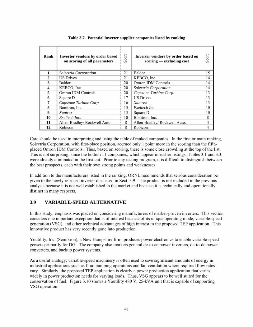
41
Table 3.7. Potential inverter supplier companies listed by ranking
Rank Inverter vendors by order based on scoring of all parameters Sc
ore Inverter vendors by order based on
scoring — excluding cost Scor
e
1 Solectria Corporation 21 Baldor 15 2 US Drives 21 KEBCO, Inc. 14 3 Baldor 20 Omron IDM Controls 14 4 KEBCO, Inc 20 Solectria Corporation 14 5 Omron IDM Controls 20 Capstone Turbine Corp. 13 6 Square D 17 US Drives 13 7 Capstone Turbine Corp. 16 Xantrex 13 8 Bonitron, Inc. 15 Exeltech Inc 10 9 Xantrex 13 Square D 10
10 Exeltech Inc. 10 Bonitron, Inc. 8 11 Allen-Bradley/ Rockwell Auto. 8 Allen-Bradley/ Rockwell Auto. 4 12 Robicon 8 Robicon 4
Care should be used in interpreting and using the table of ranked companies. In the first or main ranking, Solectria Corporation, with first-place position, accrued only 1 point more in the scoring than the fifth-placed Omron IDM Controls. Thus, based on scoring, there is some close crowding at the top of the list. This is not surprising, since the bottom 11 companies, which appear in earlier listings, Tables 3.1 and 3.3, were already eliminated in the first cut. Prior to any testing program, it is difficult to distinguish between the best prospects, each with their own strong points and weaknesses. In addition to the manufacturers listed in the ranking, ORNL recommends that serious consideration be given to the newly released inverter discussed in Sect. 3.9. The product is not included in the previous analysis because it is not well established in the market and because it is technically and operationally distinct in many respects. 3.9 VARIABLE-SPEED ALTERNATIVE In this study, emphasis was placed on considering manufacturers of market-proven inverters. This section considers one important exception that is of interest because of its unique operating mode, variable-speed generation (VSG), and other technical advantages of high interest to the proposed TEP application. This innovative product has very recently gone into production. Youtility, Inc. (Semikron), a New Hampshire firm, produces power electronics to enable variable-speed gensets primarily for DG. The company also markets general dc-to-ac power inverters, dc-to-dc power converters, and backup power systems. As a useful analogy, variable-speed machinery is often used to save significant amounts of energy in industrial applications such as fluid pumping operations and fan ventilation where required flow rates vary. Similarly, the proposed TEP application is clearly a power production application that varies widely in power production needs for varying loads. Thus, VSG appears to be well suited for the conservation of fuel. Figure 3.10 shows a Youtility 480 V, 25-kVA unit that is capable of supporting VSG operation.

42
Fig. 3.10. Youtility’s 25 KVA power converter. The advertised advantages of VSG go well beyond fuel savings. VSG technology benefits include
• Reduction in sound and vibration • Reduced production of air exhaust emissions • Increased generation time for limited fuel availability • Reduced stress on mechanical components during low-speed operation • High instantaneous overload motor start capability by using engine over speed and/or battery
reserve • Intermittent overload capability • Reduced wetstacking in the engine • Closed-loop engine speed control • Closed-loop generator voltage regulator (field control)
Other advantages of Youtility’s inverter systems related not so much to variable speed operation as to general operation include the following:
• Generator power factor near unity over the full range of output loads • No required derating for harmonic or “non-linear” loads • Multi-mode output, including 50/60 Hz, 1-phase, 3-phase, or dc • Full software control, using 50 parameters, with all necessary hardware protection • Selectable impedance and operating modes for wide variety of operational advantages • Capability to tolerate 100% unbalanced loads • Low output impedance that allows for stable parallel operation without a master control • U.L. 1741 recognition • IEEE 519-92 compliance
Youtility began production of its 25-kVA power converter in August of 2003; total production for the year is expected to be 50 units. This same model at the 3-phase, 208 Vac output voltage of interest and required maximum ambient temperature is rated at 15 kVA, which is an excellent match to the proposed TEP application.

43
Youtility provided the following survey response: Company: Youtility, Inc. Contact: Richard Griessel Phone/e-mail: 603-883-8102 ext.105, [email protected]
1. Expression of interest: Yes, we would be interested. 2. Inverter sizing — 15–20 kW is adequate based on 140oF ambient: Yes, this is reasonable.
Our 25-kVA/480-V variable-speed power electronics is rated at 125oF. For 208 V this would be about 14 kVA at 125oF and about 12.5 kVA/10 kW at 140 oF. for an overload of 400% for 1 second per our specification.
3. Sales quantity in power class of interest: In 2003 we will have delivered about 100 units. We
have had units running out in the field since 1999. 4. Reliability of product line: NA — new product.
5. Inverter size and weight in power class of interest: Approximately
70 to 90 lbs, depending on the overload requirements.
6. Cost of inverter in power class of interest: The 25 kVA in the commercial version at 1000 pcs cost about $3500 in a back panel design. This does not include the 28 Vdc.

44
4.0 ADDITIONAL DESIGN CONSIDERATIONS A main emphasis of this study is to investigate the reliability of commercially available inverters. However, an otherwise reliable inverter system may become instantly inoperative if exposed to certain non-conventional and/or nuclear-related assaults that must be considered in any thorough study of plausible threats in today’s battlefield. This section considers the vulnerability of electronic and electrical systems to an EMP and its predicted effects. The section also discusses the general methods for testing electronic systems subjected to EMP, EMP protection methods and practices, and the applicability of pertinent studies specifically to the TEP system. Finally, there is a short discussion of the potential for TEP system detection based on electromagnetic energy generated internally. The EMP vulnerability study is followed by a discussion of reliability issues or considerations in assessing the performance of inverter systems presently available in the commercial market. 4.1 EFFECTS OF EMI ON THE TQM SYSTEM Much of the information pertaining to EMI and electromagnetic damage from high-altitude electromagnetic pulse (HEMP) events and detection of electrical equipment due to EMI emissions is not available in the public domain because of the security classification concerns. There are many issues surrounding HEMP incidents and detection of power electronics-based equipment. This section surveys a number of these issues, especially for HEMP incidents, and the types of related research conducted in recent years. The section begins by considering broader research of HEMP events and effects and then narrows the scope to potential effects of interest to the TEP program and preventative measures. 4.1.1 Predicted Effects of a HEMP [14, 15] A high-altitude nuclear detonation several hundred kilometers above the center of North America will subject the land surface to an intense EMP easily spanning from the Atlantic coast to the Pacific coast. The HEMP results in steep-front, short duration transient electromagnetic fields, with rise times in the nanoseconds and decays to near zero in a few microseconds. The total energy of the gamma radiation is on the order of 4.2 x 10¹² Joules. The HEMP can create electric fields of kilovolts per meter [14]. The HEMP initially results in transient electromagnetic fields followed by geomagnetic disturbances lasting tens of seconds. The geomagnetic effects are also referred to as a magnetohydrodynamic EMP (MHD-EMP).
HEMP effects appear as flashovers and voltage-stress damage to both power delivery equipment and communications. For power delivery equipment, the greatest impact is flashover or insulation damage. A distribution transformer with a directly mounted surge arrestor is not expected to be damaged by the HEMP. Remote 480-V motors served by long unshielded runs of wire exhibit substantial risk to damage caused by a HEMP. The vulnerability level depends on the orientation and location within the area of the HEMP. Auxiliary power-to-power circuit breakers may be lost as a result of board failures or circuit breaker trips due to power surges transferred to low-voltage circuit boards. Voltage transformers may experience low-side fuse blowing, resulting in false circuit breaker tripping. Relay coils and relay rack terminal strips may flashover on ac and dc circuits. Generator unit transformers and auxiliary transformers are not expected to be vulnerable. The MHD-EMP, which follows the HEMP, contains only low-frequency components of less than 1 Hz. The strength of the pulse is on the order of 10 V/km. An MHD-EMP can affect power systems in a manner similar to a geomagnetic storm.

45
MHD-EMP exhibits itself as a quasi-dc current, which flows through grounded transformers and shunt reactors. Because of the short interval of MHD-EMP, it is unlikely that the transformer will suffer immediate, noticeable damage. However, because of the quasi-dc current, severe half-cycle saturation in transformers is possible. Grounded shunt capacitor banks have experienced neutral over-current trips during geomagnetic storms and therefore are subject to MHD-EMP impact. Over-current ground relays are subject to false tripping because of the increased zero sequence current. High-voltage dc transmission is also at risk during an MHD-EMP. Over-current trips may occur in harmonic filters. Commutation failure of inverter terminals due to severe harmonic-induced voltage distortion is also a possibility. Commutation failure is a definite possibility with a voltage distortion of 30% or higher. Converter transformers are subject to voltage distortion due to the quasi-dc current. Actual disturbance ground data from nuclear blasts have been collected, and the collection has been followed up by analyses and modeling. As a result, quantitative estimations for many events are available [14], such as flashover probabilities at several operating voltages. Quantitative estimations are also available at the component level for items such as 480-V motors fed with unshielded buried cable, underground buses, and generation loss due to certain component failures. Another study [15] estimates the vulnerability of transmission and distribution lines to flashover from an EMP created by a nuclear detonation 400 km above the earth. At four different operating voltages, 500, 230, 69, and 12 kV, the probability of the induced voltage in each phase, shield, and neutral conductor of a 3-phase system was determined. These results were compared with estimates of line insulation strength. Flashover vulnerability incorporates five major tasks:
1. Simulation of an HEMP environment: This specifies HEMP illumination as a function of direction and distance from ground zero.
2. Selection of line configuration: Representative lines and tower configurations are chosen for each operating voltage.
3. Calculation of the HEMP-induced voltages: Using a multiconductor coupling model, voltages at various locations in the HEMP zone are calculated.
4. Estimation of insulation strength: From related DOE research, estimates of insulation strength for HEMP wave shapes are used.
5. Comparison of voltage stress with insulation strength. An algorithm that approximates the HEMP field as a function of ground range and azimuth creates the HEMP environment. This algorithm assumes a constant geomagnetic dip angle12 of 70o and models a burst occurring 400 km above the earth. This yields a maximum HEMP field of 39 kV/m at the earth’s surface. It is important to note that field strength, waveshape, and polarization vary at every location. The area-of-illumination location-specific aspects of HEMP are
1. Area of illumination: Circular region on the surface subject to EMP energy. The magnitude of the incident HEMP field within the area of illumination has approximate symmetry about its magnetic north-south axis.
2. Vertically polarized HEMP field: This varies in magnitude and shape as a function of azimuth and ground range.
12 Since geomagnetic field is a vector field, at least three components are generally used to represent the field, two of them being directional vectors in the horizontal plane and the third being the vertical vector. The “dip angle” is relative to the horizontal plane and can be deduced from the three component vectors.

46
3. Horizontally polarized HEMP field: This field varies in magnitude and shape as a function of azimuth and ground range.
4. Vertical angle of incidence: Defined as the angle between a plane, tangent to the earth’s surface at the point of interest, and a ray from the burst point at altitude to the point of interest on the surface.
The induced voltages caused by a HEMP were calculated using a frequency-domain, multiconductor coupling model. In the analysis, each line was assumed to be an infinite, multiconductor line. From the tower, each end of the line was modeled as passing to infinity. Conductors of appropriate diameter represented the towers or vertical down leads on wood poles. Shield wires also were included. Only one tower or vertical ground wire at the point of interest was included in the coupling analysis, since subsequent vertical sections do not significantly impact the induced voltage. The corona effects were ignored in the model. Footing resistance was represented as a transmission line in the earth. The dc footing resistance was assumed to be 10 Ω and the earth conductivity was assumed to be 0.01 Ω/m. As a function of frequency, footing resistance ranged from 50 to 100 Ω. Line orientation has a major impact on coupling (see Figure 4.1). Induced voltage created by a HEMP varies with the horizontal angle between the HEMP path of incidence and the line. To determine the probability distribution, the illumination area was divided into 100 equally spaced locations. At each location, the line orientation was varied from zero to 360 degrees in ten-degree increments.
Fig. 4.1 HEMP event area of illumination relative to a transmission line and tower Since few data for steep-front, short-duration impulses are available; an experimentally established relationship between lightning and HEMP insulation strength can provide estimates. Preliminary tests indicate the critical flashover (CFO) voltage using a 25 by 300 nanosecond impulse varied from 1.5 to 2.0 times the CFO for the standard lightning impulse. For conservatism, a factor of 1.5 was used. Because of the steep-front nature of the wave, the CFO is assumed to be identical for surges of either polarity.

47
The study provides insulation voltage ratings based on current practice for lightning protection and the estimated range of voltages that can be expected from a HEMP event. It is found that HEMP flashover vulnerability is limited to sub-transmission and distribution lines. Specifically, the 12-kV line is vulnerable to HEMP-induced flashover. The entire range of insulation design in current use for a line of that operating voltage is vulnerable. For the 69-kV lines, only the minimum insulation designs in current use are susceptible to flashover. The 500-kV and 230-kV are invulnerable to flashover for all HEMP field levels considered. 4.1.2 HEMP Test Facility [16] Test procedures (MIL-STD-188-125) have been established to test HEMP hardness on fixed, ground-based communication sites. The three categories of testing are low-level continuous wave (CW) immersion, shielding effectiveness, and pulsed-current injection. A HEMP facility subsystem design consisting of a high quality electromagnetic barrier with minimized and protected entry points creates a standardized, low-risk protection subsystem [16]. The barrier can be viewed as a steel or copper box with welded seams that enclose and isolate virtually all mission-essential communications electronics and support equipment from the external HEMP environment. A point of entry (POE) is a location on the barrier where the shield is penetrated and HEMP energy may enter the protected volume. A POE protective device is a protection measure used to limit or prevent HEMP energy from entering the protected volume. Some common examples of POE devices include waveguides-below-cutoff, filters, surge arrestors, and closure plates for aperture POEs. All audio and data lines are fed to fiber optics outside the barrier, and the fiber optic cable is further protected with a waveguide-below-cutoff protective device. Electrical power feeder cables must be fitted with transient suppression devices. The use of an equipotential ground plane with all the grounding connections made in a manner that does not create POEs is recommended for grounding the facility. The minimum HEMP facility verification test includes a CW immersion test of the barrier, a pulsed current injection test at the electrical POEs, and any additional site-specific tests that measure the effectiveness of special HEMP protection measures. In the CW immersion test, a non-threat-level radiated CW field is swept across a frequency band, which is directed at the barrier of the facility. At the same moment, the interior of the barrier is surveyed to identify leaks in the barrier or inadequately protected aperture POEs. During the test, the facility should be in its normal operating configuration performing normal mission functions. A CW transmitting antenna is erected in one or more positions so that the field illuminates all sides of the barrier. A reference sensor is located in a clear area where its measured field has a known relationship to the total field illumination of the facility. Free-field current and voltage sensors monitor the response at defined locations within the protected volume. The shield is considered satisfactory when the test point responses remain below the noise/operating signal levels. The shielded enclosure leak detection survey (SELDS) test or a modified MIL-STD-285 shielding effectiveness test may be approved by the sponsoring agency. The SELDS test induces currents on the exterior of the facility to excite local apertures or flaws in the barrier. Sensors mounted on the shield detect and monitor leakage fields, ensuring aperture POEs do not compromise the HEMP hardening. In this test, a transmitting antenna is placed on one side of the barrier so that the test area is centered. The receiving antenna is then swept and rotated about the center of the test area until a maximum signal is detected.

48
To test the POEs, pulsed current waveforms are injected at electrical POEs. The method couples simulated threat-level EMPs to penetrating conductors at injection points outside the facility. The residual internal responses are measured and the operation of the mission-essential equipment is monitored. The waveforms are produced by precision pulse generators and are injected in both common mode and individual wire-to-ground configurations. 4.1.3 Protective Methods against EMP [17] There are several types of EMP, such as early-time, late-time, high-altitude, and intermediate, each with it’s own characteristics. However, it is the early-time EMP that produces the highest peak electric field strengths over 50 kV/m. The effects of EMP can be considered separately for various types of facility systems such as buried lines, vertical structures, and shielded equipment. The facility systems are separated into long-line effects and local effects. Long-line effects are currents and voltages induced on long power lines, communication cable links, or other conductors. Local effects are currents and voltages induced directly on the facility shield, building structure, wiring, equipment cabinets, etc. Grounding does not directly provide protection against EMP, but proper grounding techniques must be employed to prevent the creation of serious EMP vulnerabilities. Ideally, grounding a system at various locations would keep all components at a common potential. However, in reality, inductive loops, capacitive coupling, line and connection impedances, antenna ringing effects, etc. will allow significant potentials to exist within the grounding circuits. Specific ground-related practices for mitigation of EMP effects include developing a closed EMP barrier around the facility or system. A shield is helpful in excluding the incident space waves and various barrier elements on the penetrating conductors and in the apertures required for access and personnel. The shield assembly may be made of sheet steel. Continuous welding, brazing, hard soldering, or another fused metal process is necessary to minimize the discontinuities. The shield must be bonded to the earth grounding system in a number of locations in a grid configuration. Cable size should equal the size of the largest earth grounding conductor. Another ground-related practice for mitigating EMP effects is effectively dealing with the electromagnetic energy that is coupled to penetrating conductors or, in the case of the TEP system, coupled to the power distribution cables. If a structure is not shielded, EMP can couple to the cables between equipment inside. Specific types of penetrating conductors such as plumbing, grounding cables, cable shields, and electrical conduit, must be grounded by bonding to the shield wall at their energy point. Energized or signal-carrying cabling that must penetrate the shield must be treated with a barrier element, such as a surge arrester or filter that closes the barrier above a specific voltage or outside the bandpass required for signal or power transmission. 4.1.4 TEP System Application In general, small, mobile motors/generators and integrated power electronics components are very unlikely to sustain damage from a HEMP. In a mobile generator application, the compactness of the generation system provides some level of inherent protection against many of the EMP phenomena discussed in Sect. 4.1.3. For instance, small inductive loops, generally insignificant capacitive coupling, and very short internal line lengths reduce inductance and antenna effects. The compactness of the TEP system also limits the point-to-point voltages that are induced by the electric fields throughout the unit.

49
However, remaining areas of concern are the distribution network that feeds the local loads (see protective measures in Sect. 4.1.3) and the potentially vulnerable control circuitry. Ideally, an engineer will evaluate susceptibility for control circuitry by testing the entire system (i.e., the most realistic option).13 Otherwise, the controller should be isolated using fiber optics or voltage arrestors, such as metal oxide varistors (MOV), on the leads that enter the control circuit board or even putting arrestors on the input/output power leads. Enclosing the circuit in a tight Faraday cage is also helpful. The integration of PWM power inverters into the TEP system will necessarily increase the potential for detection via the production of high-frequency emissions. Of some comfort is the fact that the methods for protecting a TEP system from EMP are generally also effective for reducing the emissions of EMI and radio frequency waves. However, there is the additional need to reduce the potential for the initial generation of such emissions. The high-speed switching by logic gates to ultimately produce 3-phase waveforms will result in significant components above 50 Mhz. Thus the bandwidth of the signal can be a million times broader than the fundamental frequency. Dealing with wide-bandwidth components for effective control of EMI involves many detailed considerations in circuit and circuit board design. One readily available source [18] discusses many effective design techniques, including circuit geometry/inductance, skin and proximity effects, capacitive-induced effects, decoupling, bypassing, and snubber circuits. A mobile generator system can be hardened to be (1) resistive to EMP-induced damage while (2) containing any electromagnetic energy produced internally. Both can be accomplished through appropriate design practices, as summarized and referenced previously. It is likely that some level of testing will be necessary to gain the desired level of design verification and assurance. 4.2 RELIABILITY ISSUES Deployment of TEP into potentially a wide range of hostile environments and subjection to rough handling leads to the need for rigorous and severe reliability requirements, including shock/impact resistance, vibration tolerance, ability to survive temperature and humidity extremes, dust tolerance, corrosion resistance, EMI protection, and others, along with all functional and low-detection requirements. Although meeting requirements such as shock survivability and corrosion resistance will demand additional design effort and prototype testing, the greatest technical challenges in the inverter design effort will involve producing a reliable product while meeting certain environmental stressors which include applicable ranges of temperature and humidity. This section will focus on the especially challenging requirement that the inverter be able to operate at temperatures as high as 140oF (60oC). Issues surrounding MTBF specifications will also be presented. Humidity issues, as they relate to packaging, are discussed separately in Sect. 3.2. 4.2.1 Effects of Environmental Stressors on Reliability
The reliability of power electronics circuit design is greatly influenced by temperature. Designers in some circumstances are able to use convenient rules-of-thumb to estimate the effect that temperature increases may have on reliability. For instance, one rule states that failure rate may double for every 15oC 13 Informed opinions based on communication with Ben McConnell, Ph.D, of the Engineering Science and Technology Division, ORNL, summer of 2003. Dr. McConnell is a co-author of the ORNL report, Assessment and Testing of Long-Line Interface Devices. The report documents the effects of HEMP on power system components such as transformers, fuses, and circuit breakers in the United States.

50
increase in temperature. Many simplifying assumptions accompany such rules. In this case, it must be assumed that the design is fixed, that products are built following the same principles, and that components are equally utilized (i.e., integrated circuit chip temperatures are equal at given ambient temperature, etc.). The simplifying assumptions that give rules-of-thumb some level of usefulness are often not true and, in the case of power electronics, are generally far from true. Often, power electronics devices use switching components at temperatures relatively close to the maximum rating specified by the component supplier. It is often difficult, if not impossible, to provide much built-in margin through the use of lower operating temperatures. In addition to power electronics, there are many other important segments in the electronics industry where thermal management has become crucial. For instance, in the computer industry, the power consumption of microprocessors has been increasing for many years; and Fig. 4.2 shows how this trend is expected to continue in future years. These trends continue to put tremendous pressure on developers to advance thermal management technology and this pressure is creating significant breakthroughs.
Fig. 4.2. Power consumption trends for computer microprocessors.
[Source: adapted from CoolingZone, LLC (12)]
The temperature influence on reliability follows an exponential function, as indicated in the plot of failure rate vs. temperature shown in Fig. 4.3. In this context, a more useful rule-of-thumb is that good reliability can generally be realized if components operate at or below 0.7 Tmax as indicated in Fig. 4.2 [20]. The Tmax of chip components is generally specified as either 150o or 175oC, which means that the chip temperature should be maintained at or below 105o or 123oC, respectively. The fact that the TEP inverter application must be able to operate at 60oC results in a narrow allowed temperature rise of 45o or 63oC, respectively, if the 0.7 Tmax rule is to be observed. Since the maximum ambient temperature and the specified Tmax of the chip14 are both givens, the only recourse is to rely on the use of thick-film technology and enhanced thermal management if the designer is to successfully avoid hot spots and maintain an adequately controlled temperature rise under worst conditions.
14 However, the use of advanced semiconductor materials may offer considerable improvement in Tmax specifications during the next few years (see Sect. 6)

51
Fig. 4.3. Relationship between failure rate and device temperature. Of course, increasing the efficiency of circuit designs is extremely advantageous for minimizing the root problem, heat generated in components. This approach also reduces electrical stress in components and reduces the reliance on thermal management for maintaining acceptable junction and case temperatures. Because of the TEP program need to take a commercially proven inverter to significantly higher temperatures (i.e., from 50o to 60oC), it may be necessary not only to derate a higher-power inverter but also to improve thermal management with conventional and/or new technologies for removing heat, especially from switching components. By making aggressive use of available thermal technologies, the inverter should be able to operate at the highest required temperature and still have adequate design margin for high reliability. Another attractive prospect for more effective thermal technologies is the potential for eliminating electric fans from heat sinks and improving both reliability and electrical efficiency in the process. Fortunately, today there are a number of heat removal technologies of interest that can provide dramatic improvements. Examples include
• New materials such as composite fiber with unidirectional thermal conductivity exceeding 1100 W/m-K
• Thermosyphon loops • Dielectric liquid-filled bags • Miniature heat pipes • High-performance heat sinks • Microchannel, micro- and nano-scale heat transfer • Active thermo-electric heat removal systems
Carbon foams have been developed at ORNL that can provide high thermal conductivity. ORNL has developed a process for producing a mesophase pitch-based graphitic foam that has a bulk thermal conductivity comparable to that of aluminum. Because of the low density, the specific conductivity of the foam is more than 5 times that of copper and more than 4 times that of aluminum.

52
4.2.2 Upper Bounds on MTBF It would be profitable to briefly review some fundamental theory on reliability in order to gain insight into some overly hypothetical inverter marketing claims seen in literature today. Figure 4.4 shows the classic bathtub failure rate vs. operating time curve for failure rates. Random failures occur during the flat portion of the curve when the failure rate is constant, and this may be considered the operating lifetime of the inverter. As a result of quality controls and burn-in testing of electronic products, the manufacturer can delay delivery of the products until after essentially all infant failures. Likewise, units can be removed from service by the user before wear-out failures begin in significant numbers.
Fig. 4.4. Classic bathtub curve for reliability is useful for establishing MTBF limits. More and more frequently, manufacturers of various electronic systems (e.g., power supplies), through conservative design, careful selection of high-quality components, and rigorous quality controls, assert an empirical basis to advertise their products with claims of MTBFs in the hundreds of years. This is both to their credit and to their discredit. Although it is an impressive (assuming it is properly derived) statistic stemming from the random failure regime, it completely discounts the inevitable onset of wear-out failures. It would be more analytically precise to acknowledge the existence of wear-out when making MTBF claims. However, since the time span from when power electronics products are introduced (e.g., models, series, major redesigns) until they are discontinued is typically only a matter of a few years, wear-out is never established and never provided in product specifications. This is especially unfortunate, since this situation also precludes making use of life testing data. Life testing data, when properly collected and interpreted, are the most undisputable source of reliability data. Although wear-out is an unknown because of frequent product changes and upgrades, it is inevitable and should be acknowledged by statements such as, “MTBF is bounded by-wear out, with an onset estimated at 20 years or greater.” Further qualification may state that wear-out is a function of environmental conditions such as levels of dust, temperature, and vibration. This approach avoids the practice of advertising a product with a MTBF of 100 years when (1) it may contain components like fans that begin to wear out after one-fifth that amount of time; (2) it is unknown how certain components may degrade over decades, including plastic structural parts and switches; and (3) the long-term environmental and electrical stress effects on components is unknown.

53
5.0 DIRECTLY APPLICABLE ADVANCES IN TECHNOLOGY CECOM RDEC requested that the market investigation of state-of-the-art power electronics include not only a commercial survey but also an in-depth review of research efforts pursued by industry and academia that may ultimately help to enhance or improve the operation and performance of power electronics-based system designs. Of special interest is research investigating new materials that may be used in power electronics devices and other technologies that may lead to an increase in the capabilities and potential applications of power electronics-based power supply systems. Because of potential near-term development interest, program emphasis is placed on technologies that may become available in the next 2 to 3 years. Recent development advances have caused Si semiconductor technology to approach theoretical material limits; however, power device requirements for many applications have changed to the point where Si-based power devices cannot meet them. The requirements include higher blocking voltages, switching frequencies, efficiency, and reliability. Therefore, new semiconductor materials for power device applications are needed. For high-power requirements, wide-band gap semiconductors like silicon carbide (SiC), gallium nitride (GaN), and diamond with their superior electrical properties, are likely near-term candidates. This study compares wide-bandgap semiconductors with respect to their promise and applicability for power applications and predicts the future of power device semiconductor materials. Following this materials research, Sect. 5.2 presents cryogenic device and circuit research. For example, cryogenic power device research indicates that the performance of majority carrier MOSFET devices improves with decreasing temperature, whereas the opposite is the case for minority carrier devices. Second, CPEs using HTS technology to achieve ultra-high efficiency and high power density may be possible. Finally, the study considers new material technologies that are more effective for implementing converter control algorithms. 5.1 WIDE-BANDGAP SEMICONDUCTORS FOR USE IN POWER APPLICATIONS [21] Because an increasing percentage of the electricity generated in the future will be processed by power electronic converters in motor drives, dc-dc converters, DER interfaces, flexible ac transmission systems, and high-voltage dc systems, the efficiency and reliability of these converters is of the utmost importance. Several of these applications require voltage-blocking capabilities in the tens and hundreds of kV and thus need a series connection of many Si-based power electronic devices to achieve the necessary voltage rating. In the near future, power electronics converters will process gigawatts of power at some point between where it is generated and where it is ultimately utilized; this emphasizes the need for highly efficient power electronics converters and systems. Most present commercial power electronics devices (e.g., diodes, thyristors, IGBTs, MOSFETs) are Si-based. The performance of these systems is approaching the theoretical limits of Si’s fundamental material properties. The emergence of new power electronics devices based on wide-bandgap semiconductor materials will likely result in substantial improvements in the performance of power electronics converter systems in terms of higher blocking voltages, efficiency, and reliability, as well as reduced thermal requirements.

54
5.1.1 Properties of Wide-Bandgap Semiconductors Wide-bandgap semiconductor materials have superior electrical characteristics compared with Si. Some of these characteristics are tabulated for the most popular wide-bandgap semiconductors and Si in Table 5.1.
Table 5.1. Physical characteristics of Si and the primary wide-bandgap semiconductors [22-24]
Property Si GaAs 6H-SiC 4H-SiC GaN Diamond
Bandgap, Eg (eV) 1.12 1.43 3.03 3.26 3.45 5.45
Dielectric constant, εr1 11.9 13.1 9.66 10.1 9 5.5
Electric breakdown field, Ec (kV/cm) 300 400 2500 2200 2000 10000
Electron mobility, µn (cm2/V⋅s) 1500 8500 500 80 1000 1250 2200
Hole mobility, µp (cm2/V⋅s) 600 400 101 115 850 850
Thermal conductivity, λ (W/cm⋅K)
1.5 0.46 4.9 4.9 1.3 22
Saturated electron drift Velocity, vsat (×107 cm/s) 1 1 2 2 2.2 2.7
1or εεε ⋅= where εo=8.85×10⁻¹² F/m
Among all these semiconductors, diamond has the widest bandgap; consequently, it also has the highest electric breakdown field. SiC polytypes and GaN have similar bandgap and electric field values that are significantly higher than those of Si and GaAs. Semiconductors with wider bandgaps can operate at higher temperatures; therefore, diamond power devices have the capability to operate at higher ambient temperatures than the other materials. In addition, a higher electric breakdown field results in power devices with higher breakdown voltages. For example, the breakdown voltage of a diode is expressed in [22] as follows:
d
crB qN
EV2
2ε≈ , (1)
where q is the charge of an electron, Ec is the electric breakdown field, and Nd is the doping density.
Using Eq. (1), the breakdown voltages of diodes made of the materials in Table 5.1 are calculated assuming the same doping density, and the results are plotted in Fig. 5.1 with the breakdown voltages normalized to that of an Si diode. As seen in this figure, the theoretical breakdown voltage of a diamond diode is 514 times more than that of an Si diode. This value for 6H-SiC, 4H-SiC, and GaN is 56, 46, and 34 times that of a Si diode, respectively. Note that with a higher electric breakdown field, more doping

55
can be applied to the material, which will further increase the gap between the upper breakdown voltage limits of the wide-bandgap semiconductors compared with Si.
Another consequence of the higher electric breakdown field and higher doping density is the width reduction in the drift region of the devices. The required width of the drift region can be expressed as [25]:
( )c
BB E
VVW 2≈ . (2)
The width of the drift region is calculated for all the semiconductors in Table 5.1, and the results are plotted in Fig. 5.2 for a breakdown voltage range of 100 to 10,000 V. Diamond, as expected, requires the minimum width, while 6H-SiC, 4H-SiC, and GaN follow diamond in the order of increasing widths. Compared to these, Si requires a drift region approximately 10 times thicker. The last device parameter to be calculated from the properties in Table 5.1 is the on-resistance of the drift region for unipolar devices, which is given in Eq. (3) [24]:
( )ncs
Bspon
E
VR
µε 3
2
,)(
4= . (3)
The calculation results for on-resistance are plotted in Fig. 5.3 with respect to the breakdown voltage of the device. Again, diamond shows the best performance, with 4H-SiC, GaN, and 6H-SiC following in increasing resistance order. The on-resistance of the drift region for the Si device is approximately 10 times more than that of the SiC polytypes and GaN devices. Note that contact resistance and/or channel resistance must also be considered when the device on-resistance is calculated. These two resistances are dominant at low breakdown voltages but can be neglected at high breakdown voltages; therefore, Eq. (3) is a better approximation of the device on-resistance for higher-breakdown-voltage devices.
Fig. 5.1. Maximum breakdown voltage of a power device at the same doping density normalized to Si.

56
Another parameter to highlight in Table 5.1 is the thermal conductivity. The greater this parameter is, the better the material conducts heat to its surroundings, meaning the device temperature increases more slowly. For higher-temperature operation, this is a critical property of the material. Diamond still leads the other materials by at least a factor of five, with the SiC polytypes as the next best materials. GaN has the worst thermal conductivity – even lower than Si. For a better comparison of the possible power electronics performance of these materials, some commonly known figures of merit are listed in Table 5.2. In this table, the numbers have been normalized with respect to Si; a larger number represents a material’s better performance in the
Fig. 5.3. Resistance of the drift region for each material
at different breakdown voltages.
Fig. 5.2. Width of the drift region for each material at
different breakdown voltages.

57
corresponding category. The figure of merit values for diamond are at least 40–50 times more than those for any other semiconductor in the table. SiC polytypes and GaN have similar figures of merit, which implies similar performance levels. Si and GaAs have the poorest performance levels among the semiconductor materials listed in Tables 5.1 and 5.2, and diamond has the best electrical characteristics. Much of the present power device research is focused on SiC. In the next sections, diamond, GaN, and SiC will be compared and contrasted.
Table 5.2. Main figures of merit for wide-bandgap semiconductors compared with Si [23]
Si GaAs 6H-SiC 4H-SiC GaN Diamond JFM 1.0 1.8 277.8 215.1 215.1 81000
BFM 1.0 14.8 125.3 223.1 186.7 25106
FSFM 1.0 11.4 30.5 61.2 65.0 3595
BSFM 1.0 1.6 13.1 12.9 52.5 2402
FPFM 1.0 3.6 48.3 56.0 30.4 1476
FTFM 1.0 40.7 1470.5 3424.8 1973.6 5304459
BPFM 1.0 0.9 57.3 35.4 10.7 594
BTFM 1.0 1.4 748.9 458.1 560.5 1426711
JFM : Johnson’s figure of merit is a measure of the ultimate high frequency capability of the material.
BFM : Baliga’s figure of merit is a measure of the specific on-resistance of the drift region of a vertical field-effect transistor (FET)
FSFM : FET switching speed figure of merit
BSFM : Bipolar switching speed figure of merit
FPFM : FET power handling capacity figure of merit
FTFM : FET power switching product
BPFM : Bipolar power handling capacity figure of merit
BTFM : Bipolar power switching product
Silicon Carbide
SiC technology is the most mature one among the wide-bandgap semiconductors. It has advanced greatly since 1987 with the foundation of CREE, Inc., which is the major supplier of SiC wafers. Pending material processing problems like micropipes and screw dislocations limit the die size, but these problems have not stopped the commercialization of the first SiC power devices, Schottky diodes, with twice the blocking voltage, 600 V, of Si Schottky diodes, 300 V. Apart from the commercial devices, many other SiC power devices in the kV range with reduced on-resistances are being investigated, such as 4H-SiC and 6H-SiC pn diodes, Schottky diodes, IGBTs, thyristors, BJTs, various MOSFETs, GTOs, MCTs, and MTOs. However, except for some of the diodes, the reported devices are all experimental devices with very low current ratings.
58
The use of SiC power electronics instead of Si devices will result in system-level benefits such as reduced losses, increased efficiency, and reduced size and volume. As shown in Refs.19–22, when SiC power devices replace Si power devices, the traction drive efficiency in a hybrid electric vehicle (HEV) increases by 10 %, and the required heat sink for the drive reduces to one-third of the original size. Moreover, a dc power supply is considered in Ref. 22 and the effects of increasing the switching frequency by using SiC devices show that the sizes of the passive components, which include the transformer and the filter components, decrease proportionally. Presently, two SiC polytypes are popular in SiC research: 6H-SiC and 4H-SiC. Before the introduction of 4H-SiC wafers in 1994, 6H-SiC was the dominant polytype. Since then, both of these polytypes are used in research, but recently 4H-SiC has become the more dominant polytype. Although both of these polytypes have similar properties, 4H-SiC is preferred over 6H-SiC because anisotropy of the latter, which means the mobilities of the material in the vertical and horizontal planes are not the same. The mobilities in 4H-SiC are identical along the two planes of the semiconductor.
Gallium Nitride
Applications of GaN devices are mainly focused on optoelectronics and radio frequency uses because of its direct bandgap and high-frequency performance, respectively. However, as seen in Sect. 5.1.1, GaN also has a potential for high-power electronics applications. In the last few years, some papers have been published on high-voltage GaN Schottky diodes [30–34]. A comparison of GaN Schottky diodes with SiC Schottky and Si pn diodes at similar blocking voltages shows the GaN Schottky diode and SiC compared with the Si pn diode, mainly negligible reverse recovery current and consequently a lower switching loss that is independent of the operating temperature. The switching speed and losses of GaN Schottky diodes have been shown to be slightly better than those of similarly rated SiC diodes [30]. On the other hand, because of its wider bandgap, the GaN Schottky diode’s forward voltage drop is much higher than that of both Si pn and SiC Schottky diodes. In the literature, up to 2-kV GaN Schottky diodes [31] and up to 6-kV GaN pn diodes [32] have already been demonstrated; however, 4.9-kV SiC Schottky diodes [24] and 19.2-kV pn diodes have also been demonstrated. These figures show how advanced SiC technology is at this point compared with GaN technology. GaN has some disadvantages compared with SiC. The first one is that it does not have a native oxide, which is required for MOS devices. SiC uses the same oxide as Si, SiO2. For GaN, more studies are under way to find a suitable oxide; without it, GaN MOS devices are not possible. The second important problem is that with the present technology, GaN boules are difficult to grow. Therefore, pure GaN wafers are not available (see Sect. 5.1.4); instead GaN wafers are grown on sapphire or SiC [30–34]. Even then, thick GaN substrates are not commercially available. As a consequence, GaN wafers are more expensive than SiC wafers. An additional disadvantage of GaN compared with SiC is its thermal conductivity, which is almost one-fourth that of SiC. This property is especially important in high-power, high-temperature operation because the heat generated inside the device needs to be dissipated as quickly as possible. The higher the thermal conductivity, the more quickly the heat is dissipated. Growing GaN on SiC wafers increases the overall thermal conductivity but still does not reach the performance of SiC.
Diamond
Diamond shows the best theoretical performance, as shown earlier, with several times improvement in every category compared with every other wide-bandgap semiconductor. However, its processing problems have not yet been solved. After several years of research, SiC still has processing issues

59
because of the high temperatures required in the process; diamond is a harder material and needs even higher temperatures for processing, and not as much research has been done on its processing yet. The literature shows that diamond is used in sensors [35] and field emission devices [36]. There are no diamond power devices available yet. 5.1.2 Commercial Availability of Wafers Si and GaAs semiconductors wafers are available in diameters of up to 15 cm and variable thickness from 225 to 675 µm. Because of their abundance, they are cheap, with a price of less than $100 U.S. each. GaN and SiC wafers are not abundant; therefore, they are expensive, in the $2000 – $3000 U.S. range. Even though SiC and GaN wafers are expensive, with mass production, the prices will likely decrease to the levels of close to Si and GaAs wafers. SiC wafers are available at up to 7.5 cm with a thickness of 254–368 µm. The best SiC wafers have less than one micropipe per square; however, the most common wafers have less than ten micropipes per square with less than five micropipes per square around the center of the wafer. GaN wafers generally come in two forms: GaN on SiC or GaN on sapphire. The former is suitable for power device applications and the latter for LEDs and other optical applications. Recently, a company claimed to have produced the first true bulk GaN, but no commercial products are available yet. The diameter and the thickness of the commercially available wafers are rather small at 5 cm and up to 25 µm, respectively. 5.1.3 Commercially Available Wide-Bandgap Semiconductor-Based Power Devices As of April 2003, only GaAs and SiC Schottky diodes are available for low-power applications. SiC Schottky diodes are available from four manufacturers at ratings of up to 20 A at 600 V or 10 A at 1200 V. Note that Si Schottky diodes are typically found at voltages of less than 300 V. GaAs Schottky diodes, on the other hand, are available at ratings of up to 7.5 A at 500 V. Some companies have advertised the availability of controlled SiC switches, but none of these are commercially available yet. 5.1.4 Forecasting the Future With further development, wide-bandgap semiconductors have the potential to meet demanding power converter requirements. While diamond has the best electrical properties, research on applying it for high-power applications is only in its preliminary stages. Its processing problems are more difficult to solve than those of any of the other materials; however, it likely will be an important material for power devices in 20 to 50 years. In the meantime, transitional materials will likely replace Si for many high-power applications. GaN and SiC power devices show similar advantages over Si power devices. GaN’s intrinsic properties are slightly better than those of SiC; however, no pure GaN wafers are available, and thus GaN needs to be grown on SiC wafers. SiC power device technology is much more advanced than GaN technology and is leading in research and commercialization efforts. The slight improvement GaN provides over SiC might not be sufficient to change gears and use GaN instead of SiC. SiC is the most suitable transition material for future power devices.

60
5.2 CRYOGENIC POWER ELECTRONICS TECHNOLOGIES REVIEW The cryogenic power device research presented in this section indicates that the performance of majority carrier MOSFET devices improves with decreasing temperature, whereas the opposite is the case for minority carrier devices. Second, CPEs using HTS technology to achieve ultra-high efficiency and high power density may be possible. Finally, the study considers several technologies for implementing converter control algorithms. The investigation considers (1) ambient-temperature PWM control integrated circuits for dc-dc converters and (2) test results showing that the control integrated circuits using BiCMOS technology will outperform those with Bipolar technology. 5.2.1 Cryogenic Power Device Most of present CPEs research is focused on the devices. At this point, the invention of power devices that operate at cryogenic temperatures is still in an early stage. More research has been focused on examining the behavior of existing ambient power electronics device at low temperature [37–45]. The inventory of examined devices divides into minority carrier groups (SCRs, GTOs and power transistors), majority carrier MOSFETs, and the IGBT-MCT hybrids. Device Conduction Losses
It has been reported that power MOSFETs have significantly lower on-resistance at cryogenic temperatures. Mueller [39] has shown that the drain-source resistance, Rds, of a power MOSFET, e.g., the APT6018LNR, rated at 600 V and 35 A, drops by about a factor of 10, from 150 mΩ at ambient to only 15 mΩ at 77 K, as shown in Fig. 5.4. This feature permits the reduction of the on-resistance further by paralleling a sufficient number of devices, which has been confirmed experimentally by Gardiner [46] in a 50-kW converter. This unique feature of cryogenic operation for power MOSFETs is in sharp contrast to GTOs, which at ambient temperature, have a threshold voltage drop of about 1.0–1.5 V; this increases with decreasing temperature to the value at which the device ceases to switch. Moreover, no improvements are obtained by placing devices in parallel, and the overall dissipation cannot be reduced [38].
Fig. 5.4. On-resistance of a 600-V, 35-A power MOSFET at 300 K and 77 K. Device Switching Loss
The switching loss of devices is significant for converters to improve efficiency. The power devices’ switching behavior in a cryogenic environment has been investigated in [39, 44, and 45]. The switching losses are proportional to the rise and fall times as well as to the frequency, f, the maximum drain-source

61
voltage, and the maximum current. As shown by Jackson, the current rise time and fall times for APT 10026DN MOSFET are 19 ns and 14 ns, respectively at room temperature (RT). Thus for a 60-kVA converter operating into a resistive load with f =10 kHz, at 750 V, 82 Arms, Jackson [38] calculated that the total switching loss for a single MOSFET at ambient operation is only
WHzAVPsw 38.36/)10()1419()10()82()750( 94 =⋅⋅+⋅⋅⋅= − . At 77 K, the values for rise and fall times become shorter by a factor of 2–5, reducing the switching losses to 1–2 W [38]. Another important finding is the improvement in rise and fall times, particularly due to the driver circuit [39]. Thus the switching loss can be further decreased by improved gate drive circuit design. The per-switch switching losses can be as low as 0.2–0.4W at 77 K [38]. As for the cryogenic operation of other devices, Hudgins found the current rise times of MCTs and SCRs did not correlate to any temperature change in Ref. 34. The turn-off time of an IGBT is reduced by a factor of 4 when the temperature is reduced from 300 K to 77 K [42]. Device Simulation Model
An accurate simulation model for power semiconductors at low-temperature is critical to design low-temperature converters. To date, the circuit models for the power diode, the IGBT, and the GTO have been developed [47–49] and confirms in Ref. 43 that the model assumptions stay valid in the temperature domain T ≥ 77 K. However, the device models available for MOSFETs are not particularly accurate at predicting the switching characteristics at 77 K as shown in the simulated and measured waveform for a top switch in a half-bridge inverter [46]. Summary
Cryogenic power device research indicates that the majority carrier MOSFET devices improve with decreasing temperature, whereas the opposite is the case for minority carrier devices. The principle results of cryo-MOSFETs are (1) reduced on-resistance, (2) reduced switching time, (3) reduced reverse recovery charge and time of built-in drain-source diode, (4) smaller device capacitances, and (5) increased thermal conductivity of Si and substrates. The existing room-temperature MOSFETs, however, are not optimized for the cryogenic environment. Only when system studies provide guidance to device designers will it be possible to ascertain and realize the full potential of CPE devices. Also, independent development of low-temperature power devices may be a valuable new technology.
5.2.2 Cryogenic Power Converters Since the operation of power devices, especially MOSFETs, at cryogenic temperatures has shown potential advantages, the development of power converters using currently available commercial devices operating at cryogenic temperatures has been investigated [46, 50–58].

62
Cryogenic dc-dc Converters
Power converters capable of operation at cryogenic temperatures will play an important role in the power system architecture of future deep space missions. The design of converters that survive cryogenic temperatures will improve the power system performance and reduce development costs. Aerospace power systems are mainly a dc distribution network. Therefore, the National Aeronautics and Space Administration (NASA) Glenn Research Center has conducted a research program to evaluate a variety of dc-dc converter circuits for low-temperature operation [52–57]. Topologies included are buck, boost, multi-resonant, push-pull, and full-bridge configurations. The issues of converter switching stability, output voltage regulation, component losses, and converter efficiency have been addressed. NASA has shown that it is possible to design and operate a power electronic dc-dc converter at low temperatures using commercially available components. Slight improvements in efficiency have been observed at 77 K with no visible degradation. As an example, the converter efficiency and component loss versus temperature of a full-bridge dc-dc converter are measured by Ray [56] and shown in Fig. 5.5 and Fig. 5.6.
Fig. 5.5. Converter efficiency vs. Fig. 5.6. Converter component losses temperature [56]. vs. temperature [56].
Soft-switching converters are popular at RT because of their capability to reduce the switching losses of power devices to a negligible level. Their disadvantage is the complicated circuit configuration compared with hard-switching converters and extra losses by auxiliary devices. The switch characteristics of a hard-switching converter [57] and a zero-voltage soft-switching converter [56] at 77 K have been investigated. It was shown that hard-switching operation is improved and zero voltage switching maintained at 77 K. The advantages of soft-switching converters at RT, however, are not clear at liquid nitrogen temperature (LNT) [59]. Soft-switching circuits at LNT have not been thoroughly investigated, and different conclusions have been drawn. For example, Marx [59] comments that soft-switching at low temperature is resulting no longer in a clear increase of power density and converter efficiency, but may even result in a reduction of converter efficiency. However, Gardiner [46] concluded that soft switching must be employed to achieve acceptable switching power loss for a 3-phase inverter at LNT. HTS have been applied to implement high-efficiency inductors. Their losses are several orders of magnitude lower than those of conventional coils. Similarly, low-loss capacitors can be developed using HTS technology. In addition, ultra-high efficiency power converters using cryogenic MOSFETs and HTS have been designed [50, 56]. The use of HTS inductors could provide improved efficiency for high-power and high-current applications with low ac ripple for filtering and low switching frequency. The ac properties of HTS materials, however, must be improved for HTS coils to be beneficial in power converters.

63
Power electronics depend on semiconductor switches, and optimum device switching operation is essential to increase the converter efficiency and power density. Cryogenic power device research indicates that off-the-shelf power MOSFETs and some other devices work well at LNT. The performance of existing RT devices, however, is not optimized for the cryogenic environment achieved by simply plunging these into liquid nitrogen. To realize the full potential of CPE devices, system studies must be performed to provide design guidance to power circuit engineers and device designers. The switching characteristics of MOSFETs at LNT, such as turn-on, turn-off delays, and rise and fall times have been reported in the literature [39, 44, 45]. Unfortunately, these results correspond to specific test conditions and to a resistive load. The switching performance in most power electronic applications is with a clamped inductive load, which is significantly different from the results shown in the previous research. Another issue is the gate drive circuit design at LNT, and little research has been reported on this topic. A good gate drive circuit can reduce the switching loss and improve the reliability by protecting the device against high di/dt and dv/dt failure. Recently, a boost converter has been used to evaluate the switching performance of a power MOSFET at RT and LNT. The control circuit, gate drive circuit and power circuit for the device are immersed in liquid nitrogen. The switching waveforms are shown in Fig. 5.7. The current spike at turn-on is due to the diode reverse recovery. The voltage oscillation of Fig. 5.7(b) is caused by high c·dv/dt triggered turn-on at LNT, which is zoomed in Fig. 5.8(a). After the gate drive circuit is modified to have a negative bias, the problem is fixed and demonstrated in Fig. 5.8(b). At LNT, the MOSFET has smaller reverse recovery current and the diode has higher on-state voltage drop [60]. These first steps show that: (1) The gate drive circuit at RT needs to be modified for the device to work well at LNT; and (2) generally, the device operation is improved and has unique characteristics at LNT. How to take advantage of the unique features to optimize the device operation will become the next step for research in this area.
Voltage :10V/div
Current:10A/div
Voltage :10V/div
Current:10A/div
(a) (b)
Fig. 5.7. Switching waveforms of power MOSFET in a boost converter at (a) RT and (b) LNT [60].

64
(a) (b)
Fig. 5.8. MOSFETs switching waveforms at LNT (a) with regular gate drive circuit and
(b) with modified gate drive circuit design [60]. A hybrid soft-switching circuit of a boost converter and some initial results have been obtained at LNT. The switching waveforms and those of the hard-switched counterpart are shown in Fig. 5.9 [61].
(a) (b)
Fig. 5.9. Switching waveforms comparison at LNT: (a) hard switching and (b) hybrid soft switching [61].
The turn-on current spike for hybrid soft switching because of diode reverse recovery has been reduced significantly at both RT and LNT, but not eliminated completely. Accordingly, the switching loss at LNT is much smaller than for hard switching at LNT. When compared with conventional soft-switching techniques, the hybrid soft-switching circuit is simple to implement without auxiliary active devices and extra control. It avoids most of the problems suffered by traditional soft-switching circuits at the cost of some increased switching loss that is small and can be ignored for most applications. These preliminary results show the potential of the soft-switching technique to overcome the conventional switching disadvantages at LNT. Cryogenic Inverters
Cryogenic inverters have potential applications to high-power motor drive systems and SMES systems. Compared with a dc-dc converter, quantifying the inverter efficiency is more complicated because of the

65
increased device count numbers and complicated control and operation. A conceptual study of a 50-kW 3-phase bridge inverter at LNT was performed by Gardiner [46]. The circuit diagram of a single phase is shown in Fig. 5.10. A soft-switching scheme using zero voltage switching turn-on is applied to bridge switches. The analytical results estimate that the converter electrical losses will decrease at LNT. This has not yet been verified by experimental measurements.
Lr
Cr1
S1
S2
Load
Cr2
Vs
+
-
Vs/2
Vs/2
+-
+-
T1 T2
Vf
IloadILP
Soft switching circuit
Fig. 5.10. A single phase of a soft-switching inverter.
Summary
Power electronic converters include dc-dc converters, rectifiers, dc-ac inverters, and ac-ac converters. Research has shown that the converter efficiency at LNT may be an improvement over state-of-the-art RT implementations. In particular, CPEs using HTS technology to achieve ultra-high efficiency and high power density may be possible. The other important characteristics of power converters, such as cost, reliability, transient response, and EMI have not been studied. 5.2.3 CPE System and Control Power electronics include power components and system control. To date, most of the investigations of LNT power converters have been performed by having control circuitry at RT with the power circuitry in the LNT environment. Recently, Elbuluk evaluated the performance of a dc-dc converter by putting a PWM control circuit into a LNT chamber [62]. Electronic control of dc-dc converter power circuits is achieved by modulating the duty ratio of the controlled switch, defined as the ratio of the on-time to the switching period, to regulate the output voltage in the presence of time-varying sources and loads. There have been a large number of integrated circuit manufacturers using different technologies such as all-Bipolar, BiCMOS, or all-CMOS that provide all the necessary features to implement PWM control. Fig. 5.11 shows a typical current mode PWM control chip from Texas Instruments. These chips have been evaluated by observing the waveforms of their internal voltage reference, the oscillator frequency, and the PWM output at RT and –140 ºC. For the Bipolar PWM chip, the reference voltage maintained its value of 5 V throughout the low-temperature test. The frequency of both the oscillator and the PWM output dropped significantly at low temperature. Multiple switching occurred in the PWM output at –140 ºC. For the BiCMOS chip, the frequency and duty cycle maintained their values over the temperature range. The PWM output exhibited some occasional pulse skipping at the lowest temperature.

66
POWERGROUND
OUTPUT
Ground
RT/CT
VFB
CURRENT SENSE
8 14
7 11
RS
T
Vcc
COMPCURRENTSENSECOMP ARATOR
PWMLATCH
7 12
5 9
4 7
2 3
1 1
3 5
+-
OSC
5VREF
−
RS /
VREFLOGIC
INTERNAL BIAS
6 10
5 8
Fig. 5.11. Current mode PWM control integrated circuit. Several technologies exist to implement the converter control algorithms. So far, the operation of ambient-temperature PWM control integrated circuits for dc-dc converters has been investigated at LNT. Test results have shown the control integrated circuits using BiCMOS technology will outperform those with Bipolar technology. However, all the performances are erratic at –140 ºC and lower. The modification to the control integrated circuit design must be adopted to improve their performance at LNT. Compared with power electronics control at RT, the unique requirements and challenges of CPE control research can be summarized as follows: (1) measurements of current, voltage, etc., at high speed and at precise instants with fast control loops; (2) fast signal processing based upon the acquired data; (3) complicated user interface to control power electronics under LNT; (4) advanced monitoring to evaluate internal signals of the system; and (5) intelligence to adjust the control algorithms with the variation of the environments, such as temperature, to reach the optimum power operation and self-detection/recovery functioning. To address these issues, special control design concepts and methods must be provided by CPEs engineers.

67
6.0 SUMMARY AND RECOMMENDATIONS 6.1. TECHNOLOGY SUMMARY For the purposes of supporting a 10-kW inverter system in a relatively severe operating environment, today’s power electronics technology may be considered to be fully developed and fully adequate. Furthermore, inverter products of adequate power rating have been available in the commercial and industrial market for several years. Adapting many of these products will entail significant modification efforts, primarily in the areas of digital control circuitry and packaging; with the actual inverter circuit will require little, if any, modification. The active rectification circuit, if used, would have to be developed and matched with whatever alternator the designer specifies. This circuit may, to some extent, duplicate the inverter. Additional work may be required to provide high surge current capability possibly including energy storage for ECU startup. ORNL believes that a highly reliable and well-suited adaptation of a commercial inverter for a TEP system could be developed through a reasonable effort. Many responses were obtained during the survey stage of this study indicating a high interest and willingness on the part of motor drive and DG inverter manufacturers to adapt their products to meet the needs of the Army. Many of the responses provided information on product production numbers, reliability, physical specifications, and cost. The information was quite supportive of the ultimate goals of this program. Some responses produced information on products that contained unique features of interest, such as (1) the use of a modular design concept, (2) use of redundant circuit blocks for improved reliability/availability, (3) VSG, (4) regulated sinusoidal output, and (5) production units that meet stringent military specifications. Based on the analytical ranking process in Sect. 3.8 and special consideration given to the technical merits of one additional company, Youtility, Inc., the following companies are considered to be the most attractive for development of a TEP system in the 10-kW class:
• Solectria Corporation • Omron IDM Controls • US Drives • Square D • Baldor • Capstone Turbine Corp. • KEBCO, Inc. • Youtility, Inc.
These companies are in approximate order of their assessed merit with the exception of Youtility, Inc., which was not included in the ranking process but still was deemed one of the most promising based on the company’s technical innovation and unique features. In the review of research efforts pursued by industry and academia to improve the operation and performance of PE-based system designs, the following summary observations can be made:
1. Cryogenic power electronic research is still in its infancy. The feasibility of a mobile cryogenic generator set in the near future has yet to be established.
2. Research into wide-bandgap semiconductors, especially SiC, has expanded in recent years with
the advances in material processing. These devices will likely be inherently more robust and reliable than existing comparably-rated Si devices. Silicon carbide Schottky diodes are now commercially available, and commercial SiC switching devices will likely be available within 3 years. As these devices become available, they should be evaluated for use in future TEP systems.

68
6.2 RECOMMENDATIONS FOR PRODUCT DEVELOPMENT A digitally controlled power conversion system featuring a state-of-the-art alternator, an active rectifier, a dc link with an energy storage interface, and a 3-phase inverter output stage potentially offers many advantages, including weight reduction, improved efficiency, better performance in a wider range of alternator operating conditions, greater versatility and adaptability, and excellent reliability. The system can be designed to support motor starting, be shock resistant, and meet other requirements relating to operation in a harsh environment. As with any technology development program, a number of carefully planned activities need to be identified and integrated into an overall plan that will ensure not only successful product development from a purely technical standpoint, but development of a product that will meet an optimum number of immediate and future program needs. A product is needed that is fully adequate, is optimally versatile, and can be adapted with minimal effort/modification to meet future needs. ORNL has considered the results of this study and prior studies performed for CECOM and has identified the following recommendations:
1. A selection of appropriately sized products from a subset of the eight companies identified in Sect. 6.1 should be selected and purchased for testing at the maximum operating temperature with resistive loads and motor startup loads. This task will both verify and demonstrate that the inverters can handle the most demanding operating conditions/environment relative to the proposed military application.
2. ORNL should work in concert with CECOM RDEC to develop a full set of power converter
system specifications, including power requirements, military specifications relating to robustness and reliability, power surge capability, energy storage, features for increased versatility to accommodate potential future needs, and EMI/EMP requirements. Product cost guidelines will also be developed.
3. The issues in providing power to ECUs from TEP systems and the interaction between these
units needs to be fully understood, and designs for both of these units must ensure that they will be mutually compatible. A program is needed to assess and characterize (1) the startup current surges required by the various ECU designs and (2) the capabilities of various gensets to supply this current. Incompatibilities will be identified with recommendations for mitigating potential problems in the future.
4. Based on product analysis and testing, ORNL should contact the top prospective inverter
companies and request a design effort that will specify an alternator design and a matching power converter system that together will be capable of meeting all requirements of a 10-kW TEP system. ORNL will work closely with the designer to ensure that all electrical and physical requirements are met and that the design provides versatility and opportunities for additional features/upgrades in the future. Following development, ORNL will perform a portion of the acceptance/verification testing.
5. ORNL will investigate power electronics failures in Army equipment wherever the failures are
found (e.g., in TQGs and ECUs). This task will begin with failure data collection and efforts to obtain power electronics circuit diagrams, specifications, and examples of failed systems or components. The investigation will then focus on the information obtained and testing (if necessary) to determine likely root causes. The final report will provide a full set of technical

69
findings and recommendations for ensuring broad-scope, reliable power electronics applications in the military environment.

70
7.0 REFERENCES
1. J. B. Andriulli, M. B. Scudiere, et al, Development of Proof-of-Concept Units for the Advanced Medium-Sized Mobile Power Sources (AMMPS) Program, ORNL/TM-2001/222, Oak Ridge National Laboratory, Oak Ridge, Tennessee, March 2002.
2. J. B. Andriulli, A. E. Gates, et al., Advanced Power Generation Systems for the 21st Century: Market Survey and Recommendations for a Design Philosophy, ORNL/TM-1999/213, UT-Battelle, LLC, Oak Ridge National Laboratory, Oak Ridge, Tennessee, November 1999.
3. P. T. Krein, R. Balog, University of Illinois, Low cost inverter suitable for medium-power fuel cell sources, IEEE 33rd Annual Power Electronics Specialists Conference, 2002, vol. 1, 23-27 June 2002, pp. 321-326
4. C. L. Neft, C. D. Schauder, Westinghouse Electric Corp., Theory and design of a 30-hp matrix converter, IEEE Transactions on Industry Applications, vol. 28, issue 3, May-June 1992, pp. 546 -551
5. D. S. Parker, C. G. Hodge, The electric warship [electric propulsion], Power Engineering Journal (see also Power Engineer), vol. 12, issue: 1, Feb. 1998, pp. 5-13
6. D. O. Neacsu, IGBT- based "cycloconverters" built of conventional current source inverter modules, International Symposium on Signals, Circuits and Systems, 2003, SCS 2003, vol. 1, July 10-11, 2003, pp. 217-220
7. T. Kawabata, K. Honjo, N. Sashida, K. Sanada, M Koyama, High frequency link DC/AC converter with PWM cycloconverter, Conference Record of the 1990 IEEE Industry Applications Society Annual Meeting, 1990, vol.2, October 7-12, 1990, pp. 1119-1124
8. J. Buckley, Future trends in commercial and military shipboard power systems, 2002 IEEE Power Engineering Society Summer Meeting, vol. 1, 21-25, July 2002, pp. 340-342
9. T. M. Jahns, E. L. Owen, AC adjustable-speed drives at the millennium: how did we get here?, IEEE Transactions on Power Electronics, vol. 16, issue 1, January 2001, pp. 17-25v
10. T. Siebert, A. Troedson, et al, “AC to DC Power Conversion Now and in the Future,” ABB Inc., presented at the Institute of Electrical and Electronics Engineers, Inc.-PCIC meeting in Toronto, Canada (2001).
11. R. H. Staunton, personal conversation with Tony Siebert of ABB Inc., New Berlin, Wisconsin on May 23, 2003.
12. Ed Mayfield, “Troubleshooting Variable Speed AC Motor Drives,” Electronic Maintenance Associates, Inc. appearing at http://www.maintenanceresources.com/ReferenceLibrary/ACDrives/drive.htm.
13. V. J. Kruse, D. L. Nickel, et al., “Impacts of a Nominal Nuclear Electromagnetic Pulse on Electric Power Systems: A Probabilistic Approach,” IEEE Transactions on Power Delivery, 6(3), July 1991.
14. V. J. Kruse, T. K. Liu, et al., “Flashover Vulnerability of Transmission and Distribution Lines to High-Altitude Electromagnetic pulse (HEMP),” IEEE Transactions on Power Delivery, 5(2), April 1990.
15. A. P. Trippe, R. W. Stewart, Instrumentation Configurations for The Performance of HEMP Test Procedures, CH2903-3/90/0000-0344, Maxwell Laboratories, Inc., Institute of Electrical and Electronics Engineers, Inc., 1990.
16. “Grounding and Bonding in Command, Control, Communications, Computer, Intelligence, Surveillance, and Reconnaissance (C4ISR) Facilities,” Chapter 5 in Electromagnetic Pulse Protection, Department of the Army (CEMP), TM 5-690, February 15, 2002.
17. E. Persson, Power Electronic Design and Layout Techniques for Improved Performance and Reduced EMI, Analog Circuit Design Company, Minneapolis, Minnesota.
18. Integrated Thermal Architecture for Thermal Management of Higher Power Electronics, CoolingZone, LLC, Westborough, Massachusetts, January 2003.

71
19. Reliability Aspects on Power Supplies, Design Note 002, Northlight Optronics (formerly Ericsson Microelectronics), April 2000 .
20. R. H. Staunton, B. Ozpineci, Microturbine Power Conversion Technology Review, ORNL/TM-2003/74, UT-Battelle, LLC, Oak Ridge National Laboratory, Oak Ridge, Tennessee, March 31, 2003.
21. L. M. Tolbert, B. Ozpineci, S. K. Islam, M. Chinthavali, “Wide-Bandgap Semiconductors for Utility Applications,” presented at the IASTED International Conference on Power and Energy Systems (PES 2003), Palm Springs, California, February 24–26, 2003.
22. A. K. Agarwal, S. S. Mani, S. Seshadri, J. B. Cassady, P. A. Sanger, C. D. Brandt, and N. Saks, “SiC Power Devices,” pp. 14–21 in Naval Research Reviews, 51(1), 1999.
23. http://www.eeenet.org/figs_of_merit.asp 24. K. Shenai, R. S. Scott, and B. J. Baliga, “Optimum Semiconductors for High Power Electronic,”
pp. 1811–1823 in IEEE Transactions on Electron Devices, 36(9), September 1989. 25. N. Mohan, T. M. Undeland, and W. P. Robbins, Power Electronics, 2nd Edition, John Wiley &
Sons Inc., New York, 1995. 26. B. Ozpineci, L. M. Tolbert, S. K. Islam, and Md. Hasanuzzaman, “Effects of Silicon Carbide
(SiC) Power Devices on PWM Inverter Losses,” pp. 1187–1192 in Proceedings of the 27th Annual Conference of the IEEE Industrial Electronics Society (IECON'01), Denver, Colorado, 2002.
27. B. Ozpineci, L. M. Tolbert, S. K. Islam, and F. Z. Peng, “Testing, Characterization, and Modeling of SiC Diodes for Transportation Applications,” pp. 1673–1678 in Proceedings of the 33rd Annual IEEE Power Electronics Specialists Conference (PESC'02), Cairns, Australia, 2002.
28. B. Ozpineci, L. M. Tolbert, S. K. Islam, and Md. Hasanuzzaman, “System Impact of Silicon Carbide Power Devices,” pp. 439–448 in International Journal of High Speed Electronics, 12(2), 2002.
29. B. Ozpineci, “System Impact of Silicon Carbide Power Electronics on Hybrid Electric Vehicle Applications,” A Ph.D. dissertation, The University of Tennessee, August 2002.
30. M. Trivedi and K. Shenai, “High Temperature Capability of Devices on Si and Wide-Bandgap Materials,” pp. 959–962 in Proceedings of the 33rd Annual Meeting of the IEEE Industry Applications Society, Rome, Italy, 1998.
31. G. T. Dang, A. P. Zhang, et al. “High Voltage GaN Schottky Rectifiers,” pp. 692–696 in IEEE Transactions on Electron Devices, 47(4), April 2000.
32. M. Trivedi and K. Shenai, “Performance Evaluation of High-Power Wide-Bandgap Semiconductor Rectifiers,” pp. 6889–6897 in American Physics Institute Journal of Applied Physics, 85(9), May 1999.
33. B. S. Shelton, T. G. Zhu, D. J. H. Lambert, and R. D. Dupuis, “Simulation of the Electrical Characteristics of High-Voltage Mesa and Planar GaN Schottky and p-i-n Rectifiers,” pp. 1498–1502 in IEEE Transactions on Electron Devices, 48(8), August 2001.
34. J. L. Hudgins, G. S. Simin, and M. A. Khan, “A New Assessment of the Use of Wide-Bandgap Semiconductors and the Potential of GaN,” pp. 1747–1752 in Proceedings in the 33rd Annual IEEE Power Electronics Specialists Conference (PESC'02), Cairns, Australia, 2002.
35. K. C. Holmes, J. L. Davidson, W. P. Kang, and A. L. Stemberg, “Diamond Microelectromechanical Sensors for Pressure and Acceleration Sensing,” pp. 45–49 in Proceedings of the IEEE Microelectromechanical Systems Conference, 2001.
36. A. Wisitsora-At, W. P. Kang, J. L. Davidson, D. V. Kerns, and T. Fisher, “Diamond Field Emission Triode with Low Gate Turn-on Voltage and High Gain,” pp. 285–286 in Proceedings of the 14th International IEEE Vacuum Microelectronics Conference, 2001.

72
37. O. Mueller, “On-Resistance, Thermal Resistance and Reverse Recovery Time of Power MOSFETs at 77K,” pp. 1006–1014 in Cryogenics, 29(2), October 1989.
38. W. D. Jackson, O. S. Mazzoni, and E. Schempp, “Characteristics of Semiconductor Devices at Cryogenic Temperatures,” pp. 676–681 in Proceedings of the 31st Intersociety Energy Conversion Engineering Conference (IECEC), 2, August 1996.
39. O. Mueller, “Properties of High-Power Cryo-MOSFETs,” pp. 1443–1448 in IEEE IAS Rec., 3, October 1996.
40. K. B. Hong and R. C. Jaeger, “Experimental Survey of Semiconductor Device Operation at Low Temperature,” pp. 99–103 in Workshop on Low Temperature Semiconductor Electronics, August 1989.
41. J. L. Hudgins, S. Menhart, and W. M. Portnoy, “The Low Temperature Switching Performance of Thyristors and MOSFETs,” pp. 429–434 in IEEE PESC, June 1990.
42. R. Singh and B.J. Baliga, “Cryogenic Operation of Asymmetric n-channel IGBTs,” pp. 188–193 in 4th International Symposium on Power Semiconductor Devices and ICs (ISPSD), May 1992.
43. R. Singh and B. J. Baliga, “Cryogenic Operation of P-i-N Power Rectifiers,” pp. 193–198 in 5th International Symposium on Power Semiconductor Devices and ICs (ISPSD), May 1993.
44. S. Menhart, J. L. Hudgins, C. V. Godbold, and W. M. Portnoy, “Temperature Variation Effects on the Switching Characteristics of Bipolar Mode FETS,” pp. 1122–1125 in IEEE IAS Annual Mtg. Rec.,1992.
45. O. Mueller, “Switching Losses of the Cryogenic MOSFET and SIT,” pp. 1094–1100 in Cryogenics, 30, December 1990.
46. A. I. Gardiner, S.A. Johnson, and E. Schempp, “Operation of Power Electronic Converters at Cryogenic Temperatures for Utility Energy Conditioning Applications,” pp. 2209–2214 in IECEC, 4, August 1996.
47. D. Metzner, T. Vogler, and D. Schroder, “A Modular Concept for the Circuit Simulation of Bipolar Power Semiconductors,” pp. 15–22 in Proceedings EPE, 3, 1993.
48. T. Vogler and D. Schroder, “A New and Accurate Circuit Modeling Approach for the Power Diode,” pp. 871–876 in IEEE PESC Record, 1992.
49. T. Vogler, A. Schlogl, and D. Schroder, “Modeling and Characterizing Power Semiconductors at Low Temperatures,” pp. 237–242 in ISPSD, 1994.
50. O. M. Mueller and K. G. Herd, “Ultra-High Efficiency Power Conversion Using Cryogenic MOSFETs and HT-Superconductors,” pp. 772–778 in IEEE PESC Record, 1993.
51. T. Ise and Y. Murakami, “Control of a Superconducting Coil by a MOSFET Power Converter Operating at Near Liquid Nitrogen Temperature,” pp. 2020–2023 in IEEE Transactions on Magnetics, 27(2), March 1991.
52. S. Gerber, R. Patterson, B. Ray, and C. Stell, “Performance of a Spacecraft dc-dc Converter Breadboard Modified for Low Temperature Operation,” pp. 592–598 in The 31st Intersociety Energy Conversion Engineering Conference (IECEC), 1, August 1996.
53. M. E. Elbuluk, S. Gerber, A. Hammoud, and R. Patterson, “Performance of Power Converters at Cryogenic Temperatures,” pp. 153–156 in The 8th International Conference On Electronics, Circuits and Systems (ICECS), 1, September 2001.
54. B. Ray, S. Gerber, R. Patterson, and J. E. Dickman, “Low Temperature Performance of a Boost Converter with MPP and HTS Inductors,” pp. 883–888 in IEEE APEC Rec., 2, March 1996.
55. B. Ray, S. Gerber, R. Patterson, and I. T. Myers, “77K Operation of a Multi-Resonant Power Converter,” pp. 55–60 in IEEE PESC Rec., 1, June 1995.
56. B. Ray, S. Gerber, and R. Patterson, “Low-Temperature Performance of a Full-Bridge dc-dc Converter,” pp. 553–559 in The 31st Intersociety Energy Conversion Engineering Conference (IECEC), 1, August 1996.
57. B. Ray, S. Gerber, R. Patterson, and I. T. Myers, “Low Temperature Operation of a Buck dc/dc Converter,” pp. 941–946 in IEEE APEC Rec., 2, March 1995.

73
58. M. Elbuluk, S. Gerber, A. Hammoud, and R. Patterson, “Efficiency and Regulation of Commercial Low Power DC/DC Converter Modules at Low Temperatures,” pp. 1–6 in The 35th Intersociety Energy Conversion Engineering Conference (IECEC), 1, July 2000.
59. M. Marx, A. Schlogl, K. Eder, and D. Schroder, “Comparison of Sero-Voltage-Switching Converters at Low Temperatures,” pp. 83–88 in IEEE PESC Rec., 1, 1996.
60. H. Li, “Investigations on MOSFETs Switching Performances at Liquid Nitrogen Temperature,” submitted to APEC’04, July 2003.
61. H. Li, “Evaluation of a Hybrid Soft-Switching Circuit at Low Temperature,” submitted to APEC’04, July 2003.
62. M. Elbuluk, A. Hammoud, S. Gerber, R. Patterson, and E. Overton, “Performance of High-Speed PWM Control Chips at Cryogenic Temperatures,” pp. 443–450 in IEEE Transaction on Industry Applications, 39(2), March 2003.

74
APPENDIX A – PRODUCT INFORMATION FROM MOTOR DRIVE VENDORS This appendix contains comprehensive information on the various motor drive and inverter suppliers and their products. The motor drive product series described are primarily from the larger motor drive manufacturers/vendors in the United States since these units are commercially proven. Certain details pertaining to the motor drives have little direct significance to a potential inverter power supply developed for the TEP program; however, they are included in order to provide insight into the thoroughness and sophistication of the products and the approaches taken by the manufacturer. On the other hand, many of the specifications, features, and technical innovations described in this appendix apply directly to the inverter and should be carefully considered. Examples of these include the ambient temperature operating range, inverter carrier frequency, power handing capability, considerations that may necessitate de-rating, ability to accommodate momentary current overloads, and information pertaining to EMI and harmonic distortion. Allen-Bradley/Rockwell Allen-Bradley markets at least two series of motor drives that contain models at power levels of interest. The PowerFlex 700 series is compatible with motors from 0.5 to 40 hp and the 1336 Plus AC Drive series with motors from 0.5 to 100 hp. Both series have two basic motor control schemes: sensorless vector and volts per Hz. (The variation on the 1336 Plus AC Drive, the “1336 Impact,” features additional control features and speed control options.) The PowerFlex 700 series uses internal EMC filters, while the filters are external for the 1336 Plus. The PowerFlex 700 series includes a 25-hp model in the 400-V class; however, in the 200-V class, the 40-hp model is the closest match of interest to the TEP program. The 400-V model is smaller, measuring 13.5 in. H by 8.74 in. W by 7.87 in. D. Of particular interest from this manufacturer is its emphasis in its marketing on “custom drives.” This concept apparently extends well beyond the simple configuring of a motor drive system for a particular application. Allen-Bradley quotes the motto, “Just because you don’t see it in the catalog doesn’t mean we don’t have it or won’t develop it.” The company indicates that its custom and configured drives group will design custom hardware or software to very specific customer requirements.
Allen-Bradley has additional innovations of interest to the TEP program that are not commonly offered by the other motor drive manufacturers. The company offers a low-harmonic drive package to provide harmonically mitigated solutions to power system application requirements. The company also offers an output sine wave filter for its PWM ac drives. The main motor-related application for the filter is installations with unusually long motor cable lengths. Baldor Baldor is a manufacturer of motors (e.g., ac, dc, gear, servo), generators, controllers, and both ac and dc motor drives. Baldor offers an “ID15 Series” of ac drives suitable for motors ranging from 0.33 to 450 hp. Although these drives may not have quite as many control features as those from certain other vendors, they still typically include the more standard features such as free run or ramp stop, controlled reversing, jog speed, dynamic braking, dc injection braking, separate acceleration/deceleration rates, and an optional expanded output frequency range of 0.25 to 400 Hz. One particular Baldor motor drive model, the ID15H225-EO, appears to be well sized for the potential TEP application. This model is rated for 25-hp motors and requires 230 Vac. The drive costs $5085, weighs 66 lb, and measures 17 in. H by 10.5 in. W by 9.65 in. D.

75
GE Industrial Systems/Fuji GE Industrial Systems/Fuji (GEIS/F) markets two lines of general purpose motor drives. The CT AF-300 G11 is a drive for constant torque applications, and VT AF-300 P11 is a drive for variable torque applications such as heating, ventilation, and air-conditioning; fans; pumps; and blowers. Both types share many similarities including “soft-switching technology,” which reduces voltage spikes, especially on long cable runs to motors. This technology also eliminates the need for costly filters, reactors, and special motors in most applications. The AF-300 G11 drives span a wide range of power levels from ¼ hp to 125 hp in the 230 Vac models and from ½ hp to 600 hp in the 460-Vac models. The drives use a new generation of IGBTs that help reduce electrical noise and voltage spiking. The control system produces a “sinusoidal PWM” voltage based on torque vector control (TVC). The carrier frequency may be set from 0.75 to 15 kHz for motors ranging as high as 75 hp. The drive contains many features of interest to industry, such as motor braking using dc voltage injection and three types of speed and acceleration ramp control modes. Examples of the ramp control modes include non-linear modes (advantageous for variable torque loads) such as an “S” curve acceleration/deceleration for smooth speed transitions to reduce stresses and/or to accommodate high-inertia fan wheels. The following specifications are of interest more directly to the TEP program:
1. In ratings of 30 hp or less, the AF-300 G11 is designed for side-by-side installation with zero clearance. This demonstrates a somewhat reduced reliance on ambient air for cooling at least at either side of the casing.
2. Operation is acceptable in ambient temperatures ranging from 14 to 122oF (−10 to 50oC). Ratings up to 30 hp require ventilation covers be removed for temperatures exceeding 122oF.
3. Operation is acceptable in ambient humidity ranging from 5 to 95% (non-condensing). 4. The drive is suitable for operation at altitudes up to 3300 ft at full rating. 5. Vibration levels may be as high as 3m/s2 peak from 2 to 9 Hz, 9.8m/s2 from 9 to 20 Hz, 2 m/s2
from 20 to 55 Hz, and 1 m/s2 from 55 to 200 Hz. It meets IEC 61200-2 for vibration levels.
The 3-phase input voltage acceptable frequency range is 50 to 60 Hz with a maximum frequency variation of ± 5%. KEBCO The KEBCO Model F5 was released in 2000 and represents the company’s current technology. The F5-Basic provides sensorless TVC for simple-to-demanding motor drive applications up to 20 hp for the 230 Vac series, while the F5-General provides additional features, and models at much higher power levels up to 400 hp. Since the potential TEP application will not make use of motor-drive-related features and since the F5-Basic most likely provides adequate power, the remainder of this summary will focus on the F5-Basic. The F5-Basic can accept not only 230 -Vac, 3-phase power but also dc power. The drive features sensorless motor management and 17 pluggable control terminals (PNP-logic). There are various analog inputs/outputs and programmable digital inputs and relay outputs. There are programmable parameters with functions like S-curve, ramp stop, power off, dc-breaking, electronic motor protection, brake control, internal timer, and counter input. The drive produces output frequencies of up to 400 Hz with internal switching frequencies up to 16 kHz. The output voltage is fully stabilized. Other features include index

76
positioning function, 2 ms high-speed scan of control terminals and serial interface, internal braking chopper option, motor thermal sensor connection, and hardware current limits. KEBCO indicated, in its response to the survey that the inverter size would be 6.75 in. × 13.5 in. × 10 in., however, the size for the 20.5-hp F5-Basic (230 Vac) is listed significantly larger, 11.75 in. × 13.5 in. × 10 in. KEBCO indicated that the average cost for 15-kW units sold in 2002 was $3272. Magnetek Magnetek’s series of general purpose motor drives is designated as GPD 515/G5. This series can control a very wide range of motor sizes from 0.75 to 1750 hp. The drives are advertised as low noise and able to supply high starting torque. The GPD 515/G5 series includes features such as dc injection braking for ramp or coast, electronic reversing, adjustable acceleration/deceleration, critical frequency rejection (1 or 2) with adjustable bands, selectable torque limits, output frequencies from 0.1 to 400 Hz, jog, and efficiencies from 96% to 98%. The drives use 32-bit microprocessor logic. The carrier frequency is selectable up to 15 kHz. Protective features are many, including the following:
• Current-limited stall prevention • Synchronized start into turning motor • dc bus charge indicator • Phase-to-phase short circuit protection • Phase-to-neutral short circuit protection • Ground fault protection • Electronic motor overload protection • Current and torque limits • Fault circuit: overcurrent/overvoltage • Over-temperature protection
It is noteworthy that ORNL has had positive experience15 with a Magnetek drive (i.e., 50-hp, Model GPD 505) used in a wide variety of research projects over several years. The GPD 515/G5 series is designed for operation in ambient temperatures from 14oF to 113oF and in non-condensing humidity to 95%. The drive can operate in altitudes of up to 3300 ft without derating. The lower-voltage units for 25-hp operation require from 200 Vac to 230 Vac, 3-phase. An appropriately sized Magnetek drive for inverter adaptation would be the CIMR G5M 2018, which will operate a 25-hp motor from a 230-Vac supply. The unit weighs 71 lb and measures 24 in. H by 13 in. W, and 11.22 in. D.
15 A Magnetek drive was used in an Electric Machinery Test Center (EMTC) for 3 years (1997–2000) and then in a power electronics laboratory from 2001 to the present. Similar-sized drives from two other manufacturers were also used in the EMTC. The Magnetek drive was found to be much more user-friendly and compact than those from other manufacturers.

77
Omron IDM Controls Omron’s general-purpose P5+ Series inverters are designed for use in variable- and constant-torque motor drive applications. Omron also markets a G5+ multipurpose inverter series that is suited for constant torque applications. The P5+ Series includes built-in proportional integral derivative (PID) control and energy-saving software that will help the user obtain the theoretical maximum efficiency for the motor and improve overall efficiency. The P5+ Series inverter can tolerate +10%/−15% voltage fluctuations and ±5% frequency fluctuation. The inverter can also withstand a 150% overload for 1 minute and an instantaneous overload of 200%. It has a 2-second power loss ride-through capability. The carrier frequency is adjustable up to 15 kHz. The allowable operating ambient temperature range is 14 to 104oF increasing to 113oF in an open chassis16 and the maximum altitude is 3280 ft. Humidity may be 95% with no condensation. The P5+ Series drive accepts 5 multifunction inputs, both analog and serial (RS-232). The serial communication relies on Modbus and, using an option card, various others such as Apogee, Metasys, LonWorks are also available. There are three multifunction outputs and Programmable Form C contact output. Other special features include dc injection at starting, V/Hz operation, 16-bit microprocessor, 0.1–400 Hz control range, and the use of jump frequencies. Protection features are provided for overvoltage, undervoltage, overcurrent, overtorque, overheat, inverter overload, motor overload, dc bus charge indication, and loss of PID feedback. The Omron P5U-2015-N1 is a 230-Vac, 3-phase model rated for 25 hp. The dimensions of this 24-lb inverter are 15.75 in. H by 9.84 in. W by 8.86 in. D. The smaller, 15/20-hp model has the same weight and dimensions except for 15 in. height in this case. Reliance Electric Reliance Electric markets several series of motor drives; however, the only three that are applicable to the TEP system needs are the SP500, SP600, and GV3000/SE. The SP500 series is limited to 20 hp, which is the lower limit of the required TEP system power needs. The SP600 and GV3000/SE both have a 25-hp model, which is a size of greater interest. The SP 600 is a full-featured industrial ac drive suitable for many motor drive applications. The drive operates under two control modes, the volts/Hz mode and the sensorless TVC mode. The drive provides 0.5% speed regulation and operates with a selectable switching frequency from 2 to 10 kHz. When the IGBTs are switched at 10 kHz, the PWM waveform induces significantly less audible noise in the motor. The drive contains many features of interest to industry, such as motor braking using four different modes and various kinds of speed and acceleration ramp control modes. One of the ramp control modes provides an “S” curve acceleration or deceleration for smooth speed transitions to reduce stresses and/or to accommodate high-inertia fan wheels. One of the optional kits is an EMC line filter. The Model SP600-6SB401-034CTANA operates on 480 Vac, produces 25 hp, and weighs 27.6 lb. Dimensions are 12.6 in. H by 8.74 in. W by 7.87 in. D. Price data could not be found readily for the 25-hp model; the 20-hp model is priced at $2844.
16 In apparent conflict, Omron’s website also specifies a maximum ambient temperature of 122 oF for the same series of inverters.

78
The GV3000/SE drive differs from the SP600 in that it has additional features of interest to motor control in industry. For instance, it features a third method of control called flux TVC. The GV3000/SE can provide 1 to 100 hp at 200–230 Vac and 1 to 400 hp at 380–460 Vac. A 25-hp model operating on 200–230 Vac weighs 35 lb and measures 17.4 in. H by 11.3 in. W by 9.4 in. D and costs $4345. Robicon Robicon produces several series of motor drives with power handing capabilities extending up to thousands of hp. The two series of interest for potential TEP adaptation are the 454GT Series and the ID Series. The 454GT is based on IGBT technology and PWM space vector waveforms. The space vector modulation “spreads out” the audible energy over a wide range of frequencies so that the motor noise is less noticeable. Another item of particular interest is that Robicon states that it is amenable to producing drives with pre-engineered options or custom units. The 454GT drive provides acceleration and deceleration rates that are selectable from 1 to 3200 seconds. Current limits are 120% for 1 minute for variable torque or 150% for 1 minute for constant torque. The drive provides a 5 cycle power loss ride-through capability and a 2-second control power ride-through capability. The drive’s output frequency range is 0 to 400 Hz, and it can provide forward and reverse jog, can provide drive to an already rotating motor, and, as an option, can provide dynamic braking. The efficiency of the 454GT drive is 98% at full power. The ambient temperature range for the 454GT drive is 32 to 104oF, and the maximum altitude is 3300 ft. Robicon sells a 454GT drive for 18.5 kW which, in the 380-V model, weighs 65 lb and measures 21 in. H by 14 in. W by 12 in. D. The ID Series of Robicon drives is similar except for the following significant differences:
• Different enclosures, generally NEMA 4 • Ramp times of 0.1 to 600 seconds • Standard dynamic braking of up to 200% depending on model • Carrier frequency range of 3 kHz to a very high 16 kHz (see below)
Although the carrier frequency range is extended, Robicon acknowledges that inverter heating at high frequencies increases significantly. At 16 kHz, the advantage of reduced noise can be offset in full-power applications by the need to derate the inverter. Robicon’s unique solution is the Autoselect feature that determines the highest possible carrier frequency without overheating the inverter. The 25-hp ID Series drive, with its very sturdy NEMA enclosure, is both heavier and larger than the corresponding 454GT unit. The 25-hp ID Series drive weighs 127 lb and measures approximately 29 in. H by 16 in. W by 12 in. D. Siemens Siemens’ main line of motor drives is the Simovert Masterdrives produced in Germany. The drives are described as “ac drive converters” that transform motors into high-accuracy VSDs. They represent a flexible design approach/product and can be used with supply voltages throughout the world. The open-loop control is optimized for the two product subgroups: VC and frequency control in the VC series and servo control for the highest dynamic performance in the MC series.

79
Simovert Masterdrives are designed using a unified approach throughout the power range (i.e., 0.55 to 250 kW for the MC series and 2.2 to 5000 kW for the VC series) of the product line. The drives provide all 3-phase voltages from 200 to 690 V. The drives have a uniform operator control philosophy and they can be combined as required even with units of different control versions. They provide appropriate solutions as system modules whether they are used as single drives or as multi-motor drives. Simovert Masterdrives can be expanded in a modular fashion using operator control panels, terminal expansion modules, braking modules, and input/output filters. The drives feature high speed/torque accuracy, wide dynamic performance, high overload capacity, and high power density. The drives can be obtained with radio interference suppression filters for grounded and non-grounded supply networks. These filters provide EMI suppression levels according to EN 55011 and EN 61800-3. Each unit is thoroughly tested before leaving the factory. A DIN/ISO 9001 certification is included for the complete production area including contract administration and logistics. Square D Square D produces and markets an Econo-flexTM motor drive and several panel-mounted and packaged versions of the full-featured ALTIVAR drive. Since the TEP program interest is mainly in the inverter circuit, a closer look was given to the Econo-flex design. Actually, Square D indicates that the Econo-flex design uses ALTIVAR 58 drive technology in uniquely packaged power converters. The Econo-flex Class 8839 series includes a 25-hp, 208-Vac model. The Econo-flex design has a motor drive frequency range of 0.1 to 500 Hz and a switching frequency of 0.5 to 16 kHz; however, for switching frequencies higher than 8 kHz, it is recommended that the next-higher 30 hp drive size be used. The drive uses IGBTs that produce a PWM output waveform. Acceleration and deceleration ramps can be set for 0.1 to 999.9 seconds. The drive operates typically with a 97% full-load efficiency. The Econo-flex may be operated from 14 to 104oF in 95% humidity with no condensation or dripping water, conforming to IEC 60068-2-3. It may be operated at up to 3300 ft without derating and then derated by 1% of current for each additional 330 ft. Acceptable operational shock is 15 g, 11 ms. Although the 25-hp, 208-V unit is heavy (i.e., 180 lb) and measures a relatively large 49 in. H by 21 in. W, and 16 in. D, the cabinet has a far smaller metal chassis subassembly inside that contains the power converter. The cabinet and components are not space or weight optimized, consistent with ease of maintenance and low cost. US Drives US Drives offers the Phoenix DX and EX series of AC Vector drives that are made in the US and cover a wide range of power, 3 to 3500 hp. Within this power range, the company produces two 25- to 30-hp versions that are rated for either normal overload capacity, 120% rated output current for 1 minute, or high overload capacity, 150% rated output current for 1 minute. Since additional control features are of minimal interest, this discussion focuses on the more basic DX version. The Phoenix DX uses space TVC to produce a sine coded PWM waveform with programmable carrier. The Phoenix DX design has a motor drive frequency range of 0 to 600 Hz and braking torque of approximately 20%. Acceleration and deceleration ramps can be set for 0.1 to 3200 seconds, or “S curve” control can be used. The drive operates typically with a 97% or greater full-current efficiency. Line voltage surge protection and a radio frequency interference (RFI) input filter are standard on all models.

80
The Phoenix DX also has short circuit and ground fault protection and the ability to synchronize to an already spinning motor and operate through a 2-second power dip (i.e., no loss of control). The drive has multi-function I/O and custom volts/Hz programming can be used. The Phoenix DX may be operated from 14 to 122oF in 95% relative humidity with no condensation. It may be operated at up to 3300 ft without derating. Acceptable operational shock is 9.8 m/sec2 (1.0 g) peak. The 25–30 hp, 208-V unit measures 27 in. H by 12.7 in. W, and 11.9 in. D for the NEMA 1 enclosure option. The survey response provides size information for the inverter itself. US Drives was the first company to respond to our survey, and its very positive response came following a single request for information.

81
APPENDIX B – PRODUCT INFORMATION FROM DISTRIBUTED ENERGY RESOURCES VENDORS
This appendix provides information collected during an investigation that sought to characterize power converters used specifically for use with microturbines. This characterization was being performed to facilitate an assessment of the present status of marketed power conversion technology to determine how versatile the designs are for potentially providing an expanded range of services to the grid necessitated by changes in market direction, new industry standards, and the critical needs of the local service provider. The project included data gathering efforts and documentation of the state-of-the-art design approaches that are being used by microturbine manufacturers in their power conversion electronics development and refinement. This project entailed a review of power converters used in microturbines sized between 20 kW and 1 MW. The power converters permit microturbine generators, with their non-synchronous, high-frequency output, to interface with the grid or local loads. The power converters produce 50- to 60-Hz power that can be used for local loads or, using interface electronics, synchronized for connection to the local feeder and/or microgrid. The power electronics enable operation in a stand-alone mode as a voltage source or in grid-connect mode as a current source. Some microturbines are designed to automatically switch between the two modes. General Electric (GE) is discussed as a developer of a new microturbine product. GE was not mentioned earlier in this report because it has not yet marketed its microturbine; therefore, its inverter cannot be considered to be proven in the market. Also, the study did not include companies like Solectria that did not directly support the microturbine industry. For information on Exeltech, Inc., and Solectria, see the supplemental section at the end of the appendix (Sect. B.2). The information provided in this appendix is adapted from Ref. 7. B.1 VENDORS AND MANUFACTURERS GE, which is well along in its development of a relatively large microturbine, was also helpful in providing information and is included in this data summary. Ballard has developed a 110-kVA microturbine system (i.e., power converter system) that the company says is capable of operating in grid and stand-alone modes with all the grid connect and retry strategies in accordance with IEEE 1547.17 The investigation of Capstone inverters was performed using (1) responses from the company, (2) information obtained through visits to three research sites18 where Capstones are used, and (3) a review of Capstone documentation. All of the companies were asked in a series of questions to provide details pertaining to (1) their microturbines or the microturbines from other manufacturers that make use of their power converters, (2) technical aspects of the inverters, (3) technical issues such as power quality, and (4) electronic component details. Table B.1 provides information on the microturbine generator type, packaging, power converter switching frequency, features, and manufacturer. The most detailed information is listed under the two current manufacturers of microturbine inverters, Bowman and Capstone. Detailed information for GE’s product was also obtained because GE is well along in developing a specific microturbine product. Clearly, 17 IEEE 1547 is the Standard for Interconnecting Distributed Resources with Electric Power Systems (See Sect. 4.1.2.) 18 Project staff inspected a 30-kW Capstone microturbine at the CHP Integration Laboratory – A National User Facility at ORNL, a 60-kW Capstone at the High Temperature Material Laboratory (HTML) at ORNL, and a 30-kW unit at the EPRI PEAC Corporation in Knoxville, Tennessee.

82
power converters are being designed by the manufacturers for use with synchronous generators, although Xantrex indicates that it is also willing to adapt designs to non-synchronous machines. Current power converter products are modular and integrated into the microturbine; however, for GE’s 175-kW design, external packaging of the converter is planned. Power converter switching frequency is generally up to 8 kHz for the different manufacturers, although Xantrex designs may use much higher frequencies.19 A key feature indicated in Table B.1 is that all of the manufacturers use some type of reprogrammable digital control system for the inverters. This provides a potentially needed level of versatility that may become critical in the future. The modes of operation generally include stand-alone (i.e., for supplying power to local loads only) and grid-connect, which must be synchronized to the grid. The GE microturbine is planned for grid-connect operation only. Switching between modes is a major issue. The quality or speed of the transitions from one mode to another varies from manufacturer to manufacturer and also depends on the mode to which the unit is being switched. The transitions generally cause a voltage interruption. This can be a significant problem in many of today’s applications in industry and in the commercial sector. Only Ballard claims to have completely seamless transitions; however, this must be demonstrated in a microturbine system and made available in the commercial market. The Capstone microturbine has stand-alone and grid-connect modes with automatic switching between them. Transferring from grid-connect to stand-alone takes 2 to 4 minutes, while returning to grid-connect takes only 5 seconds.
19 Higher switching frequencies generally come with a power de-rating penalty.

83
Table B.1. Microturbine manufacturer, operating parameters, and general features
Subject Ballard Bowman and Elliott1 Capstone Turbine Corporation
General Electric Xantrex
Type of generator used in microturbine
Synchronous Synchronous Synchronous PM generator
Synchronous PM May be used with synchronous or non-synchronous
Packaging of overall unit
Modular circuit Integral packaging Integral packaging Power converter in nearby cabinet
Not currently integrated in package
Turbine speed range Customer dependent 68,000 rpm (normal) 45K–96K rpm 12–50K rpm NA Power converter switching frequency
4–8 kHz 8 kHz Unknown ≤8 kHz rectifier, ≤5 kHz inverter
2–18 kHz depending on power level
Modes of operation and seamlessness of transfer
Stand-alone and grid-connect (seamless switching possible)
Stand-alone and grid-connect with sub-second switchover
Stand-alone and grid-connect with auto-switching (see text)
Grid-connect only Stand-alone and grid-connect (interruption only when grid V drops)
Type of digital control Microprocessor (reprogrammable)
Microprocessor (reprogrammable)
Digital signal processor
Flash-based microprocessor
Digital signal processor by Texas Instruments
Accessories for operation in different modes
Unknown Optional dual-mode switch required for grid independent mode
Battery required for stand-alone mode and black start (see text for other accessories)
NA Uninterruptible power supply required for black start of microturbine
Power rating of power converter
10 to 110 kW 60 and 80 kW 30 and 60 kW (200 kW future)
175 kW @ 40oC Power converters from 5 to 1 MW
Manufacturer of mechanical portion
No microturbine product or application at present
Elliot Energy Systems Capstone General Electric No microturbine product or application at present
Manufacturer of power converter
Ballard Power Systems Bowman Power Systems Capstone General Electric Xantrex
Cost of power converter and/or microturbine
Depends on application --- ~$30,000 for the 30-kW model microturbine
TBD when product is introduced into market
$70/kW to $1000/kW for power converters depending on application
1Power converters supplied by Bowman Power Systems.

84
The Capstone can be used with other accessories than the battery listed in the table. For instance, a dual-mode controller will permit the microturbines to operate with up to 20 units, and a PowerServer device will permit operation of up to 100 units. The purchase of an external power meter will facilitate operation with reverse power protection and load following. Table B.2 lists the various types of ancillary services that the power converters are capable of supplying to the grid. The listing also includes a few special features of interest, such as operation by remote control and monitoring device and communications that support operation of multiple microturbines in a parallel configuration. A review of Table B.2 shows that, with the exception of Bowman/Elliott and GE, the power converter manufacturers claimed an extensive list of ancillary services and special features. The analysts strongly suspect that in some cases, claims may have been made on a more theoretical basis to reflect potential capabilities. Therefore, some level of caution is advised in considering the implicit claims indicated by the table. However, this is essentially a moot point for the purposes of this study, since the primary goal of the study is to determine exactly this — the potential features of the microturbine power converters. As indicated above, the Capstone load-following service and reverse power protection feature require the use of an accessory, an external power meter called the “pulse issuing power meter”. Table B.3 shows a summary of the microturbine power converter topology, the type of switching components used, key thermal specifications, cooling method, and power quality concerns if any exist. For all manufacturers, the table indicates many similarities including a dc link topology, PWM waveforms in the inverter output, and some type of forced-air heat sink arrangement except for Ballard, which uses liquid cooling. Certain topics, such as how close the switching devices operate to their maximum ratings, proved to be too sensitive to result in any significant response from the companies. The filtering referred to in the bottom two rows of the table has proved effective for all manufacturers in producing an output waveform that does not produce EMI, is sinusoidal in shape, and often exhibits lower harmonic distortion than found on the local grid. Regarding the type of circuit topology, GE provided additional details regarding its 175-kW power converter. The 3-phase, two-level active IGBT power electronic bridge converts the 3-phase, high-frequency generator voltage to dc. The voltage on the dc link is regulated by the active rectifier and it feeds a 480-V, 3-phase IGBT inverter. The dc link voltage is also monitored so that turbine loading and speed can be adjusted according to the apparent inverter loading of the dc link.

85
Table B.2. Microturbine ancillary services and special features
Subject Ballard Bowman and Elliott1 Capstone Turbine Corporation
General Electric Xantrex
Voltage sag support Yes Possible Yes Static VAR compensation
Yes Can select 1.0 to 0.6 leading/lagging power factors (Elliot)
Possible Yes – power factor control only
Yes
Load following Yes Yes Yes Yes Operating reserve (spinning or non-spinning)
Yes Yes
Backup supply Yes Yes Yes Black start capability (without external grid)
Yes Grey start available provided gas is present and oil is warm
Yes Yes
Remote controllability Yes Yes Yes Yes Communication (operation in parallel with other units)
Yes – has multi-unit capability for up to 10 units in parallel.
Yes Yes, using the standard MultiPac RS485 communications port
Yes
Others Reverse power protection (in Elliot microturbine, therefore an assumed feature of Bowman)
Peak shaving, reverse power protection, and auto-restart (following a fault)
1Power converters supplied by Bowman Power Systems.

86
Table B.3. Microturbine circuit topology, components, thermal specifications, and power quality concerns
Subject Ballard Bowman and Elliott1 Capstone Turbine Corporation
General Electric Xantrex
Identify circuit topology
dc link converter dc link converter dc link converter (current regulated)
dc link converter (see details in text)
Voltage source dc link converter
Identify type of waveform generated
PWM PWM PWM PWM High frequency sine-triangle PWM
Identify type of power devices in inverter
IGBTs IGBTs or IPMs by Semikron/IR
IPMs using IGBTs IGBTs manufactured by Powerex
IGBTs or IPMs by Eupec, Powerex
Switching devices operate how close to maximum ratings?
No information provided
Confidential No information provided
Dependent on factors such as load and speed (see text)
No information provided
Maximum ambient T 40oC 45oC 50oC 40oC without derating 45oC (min. is −20oC) Maximum device junction temperature
Unknown 150oC Unknown 125oC 150oC (not operated above 110oC)
Method of cooling of power switching components
Water/liquid cooling Force air cooling with heat sink
Force air cooling with heat sink
Forced air cooling with heat pipe heat sink
Forced air cooling with heat sink or water cooled
Permissible overload current
No information provided
300% of peak rated for two cycles
200% for 1s, 150% for 10s, 125% for 30s, and 110% for 60s
This design parameter is TBD
Depends on application
Filtering and shielding Both are used Both are used Both are used Filtering included for harmonics and EMI
Both may be used
Power quality considerations
No EMI or harmonic distortion problems
No EMI or harmonic distortion problems
No EMI or harmonic distortion problems. Harmonics well below IEEE 519 limits.
Harmonic levels will meet IEEE 519
No EMI or harmonic distortion problems
1Power converters supplied by Bowman Power Systems 2THD = total harmonic distortion

1
GE also supplied additional details regarding how close the switching devices operate to their maximum ratings. Obviously, this depends on the output voltage of the generator and other factors such as load and speed. GE follows general design rules of 10% voltage margin for the main power electronics. This may seem to be a tight margin but, in reality, how appropriate it is can be determined only from the design details.20 GE is still developing the overall circuit control strategy and will be operating the power conversion electronics for the first time in the spring of 2003. GE will be assessing device stress as well as other system operating points, and its test results will determine whether the bridge is correctly used and rated. GE states that sophisticated junction temperature techniques are used to maintain device temperatures within published limits. The final question asked of manufacturers was what product or component would they like to see from the government or industry that would be of help to them. The responses shown in Table B.4 were obtained from Ballard, GE, Capstone, and Bowman Power Systems.
Table B.4. Present industry needs from the perspective of power converter manufacturers
Manufacturer Needs from the government and/or industry Ballard Ballard states that they would like to see funding for high-voltage/current
SiC diode development. Bowman and Elliott Bowman Power Systems indicated that it is desirable to have a sustained
incentive, either by way of a fund or a geographic-supported region, which developers could rely upon over a number of years to provide a proving ground for the technology.
Capstone Turbine Corporation
Capstone indicated that they would like to see continued development and adoption of interconnection standards.
General Electric GE stated that they would like to see the implementation of codes and standards to improve and accelerate technology acceptance.
Xantrex No response Turbec AB’s mostly European product has a number of interesting features worth reviewing. Their T100 microturbine is rated at 105 (±3) kW, has a nominal speed of 70,000 rpm and is designed for operation indoors only. The unit provides combined heating and power with a gas-water, counter-current flow heat exchanger providing a 122 to 158oF temperature rise. The net electrical efficiency is 30%, while the net total efficiency is 78% assuming full use of the heated water. A two-pole PM high-speed generator feeds 500 Vac, 2333 Hz to a dc link converter that produces 400 Vac, 3-phase, 50 Hz or alternatively 480 Vac, 60 Hz. The converter can be operated in reverse to use the generator as a starter motor for the microturbine. A power module controller controls and operates the entire electrical system. The T100 features a communications connection that permits the operator to monitor and control the microturbine from a remote location.
20 GE is currently using 1400-V parts with about a 900-V dc Link. GE attempts to apply 10% extra margin after all worst-case control and transient effects have been accounted for. Hence, device switching transients will be added to the 900-V link voltage before the margin is applied. The switching transients can be controlled by altering the gate drive characteristics and stray bus inductance. It is possible to require less margin if higher-performance bridge topologies (buswork) and controls are used. Manufacturers apply margin based on their experiences, control complexity and response, such as the ability to control the dc link voltage during input/output transients, and power electronic bridge design. It is very advantageous for an equipment manufacturer to achieve a higher rating or extra performance over a competitor’s product by developing its own philosophy for rating and application capability.

2
B.2 ADDITIONAL VENDORS (SUPPLEMENTAL INFORMATION) In addition to information from the recent ORNL study [14] that is summarized/adapted in Sect. B.1, this section supplies information on vendors of inverter systems who have not focused primarily on the microturbine industry but whose products are proven in other commercial, industrial, and/or military applications. Exeltech Exeltech produces a unique MX series of redundant, modular inverter systems in which no single malfunction will cause the inverter system to fail. Modular amplifiers for each phase or master control module can be slid into and out of the cabinet even during operation. Thus, the modules can be replaced without interruption in power to critical loads. The MX system can be configured for power levels of up to 60 kW at 208 Vac, 3-phase with many input voltages available. In the MX system, the control card and any number of additional 1-kW power modules combine in parallel to make a standard inverter. This makes possible two other unique features of the MX system: it can be expanded as power requirements increase and also upgraded to be N+1 redundant as desired. The primary features of the MX system are
• The system can be easily made N+1 redundant. • An existing system may be easily expanded. • A true sine wave is produced. • Modules are “hot” insertable. • It can provide remote switching and remote metering.
The output of the MX system is regulated so that no measurable voltage change occurs in the output as the input voltage fluctuates. Less than a 0.5-V change occurs in the output when the load varies from 0 to 100% rated. The output sine wave has a 2% maximum distortion. The MX system is lightweight; power modules weigh 7 lb each for a typical total of 28 lb minus the cabinet. ORNL believes that, in spite of the unique and attractive features described above, building up 15-20 kW inverters for the proposed application from 1-kW modules (before thermal derating) is not desirable. Exeltech’s new, higher-powered GX series featuring 3.6 kW modules would be more practical; however, the GX series is only in the bench-testing phase as of December 2003. This study has sought out only market-proven designs. Solectria Solectria produces a line of digital microgrid inverters (DMGIs) and digital motor controllers that can be used for DG. For instance, the Model DMGI445 is a 38-kW inverter designed for operating on 312 Vdc input and producing 208 Vac, 3-phase, 50/60 Hz. Although the input voltage may be as low as 100 Vdc, the output voltage is proportionately lower. The DMGI is DSP-controlled, rugged, and waterproof. The main features of the DMGI are two-way power flow, space vector PWM circuitry, internal safety contactor for grid isolation, drivers for control signals to engines and other power electronics, lightweight aluminum chassis, and trenchgate IGBTs for maximum efficiency. The units have an RS232 connection for diagnostics and data visualization, connections for communications with other components, and internet interactive transfers for remote diagnostics and software upgrades.

3
Safety features for the Solectria DMGI include over-voltage and under-voltage protection, three levels of over-current protection, over-temperature protection, and invalid signal detection. Other protective features are based on fuel cell or engine operations. The DMGI efficiency is 96–98%, and various types of output filters are available. The 38-kW inverter has a peak power rating of 75 kW that would be helpful in supporting startup of loads that have a high initial surge current.

4
DISTRIBUTION
Internal
1. D. J. Adams 2. J. D. Kueck 3. J. W. McKeever 4. B. Ozpineci
5. R. H. Staunton 6. T. J. Theiss 7. L. M. Tolbert
8–9. Laboratory Records
External 10-14. Selma Matthews, CECOM Power Generation Branch, 10106 Gridley Road, Ft. Belvoir, Virginia
22060-5817. 15. Ed Nawrocki, CECOM Power Generation Brance, 10106 Gridley Road, Ft. Belvoir, Virginia
22060-5817. 16. Edward P. Plichta, U.S. Army CERDEC, C2D, AMSEL-RD-C2-AP Fort Monmouth, New
Jersey 07703-5601. 17. Paul Shivley, CECOM Power Generation Brance, 10106 Gridley Road, Ft. Belvoir, Virginia
22060-5817. 18. Omar Winn, CECOM Power Generation Brance, 10106 Gridley Road, Ft. Belvoir, Virginia
22060-5817.