Embed Size (px)
Citation preview
I:\SDC\06\WP\SDC 6-WP.3.docx
E
SUB-COMMITTEE ON SHIP DESIGN AND CONSTRUCTION 6th session Agenda item 3
SDC 6/WP.3
7 February 2019 Original: ENGLISH
DISCLAIMER
As at its date of issue, this document, in whole or in part, is subject to consideration by the IMO organ to which it has been submitted. Accordingly, its contents are subject to approval and amendment
of a substantive and drafting nature, which may be agreed after that date.
REVISED SOLAS REGULATION II-1/3-8 AND ASSOCIATED GUIDELINES (MSC.1/CIRC.1175) AND NEW GUIDELINES
FOR SAFE MOORING OPERATIONS FOR ALL SHIPS
Report of the Working Group GENERAL 1 The Working Group on Safe Mooring Operations, chaired by Dr. S. Ota (Japan), met from 4 to 6 February 2019. 2 The Group was attended by delegates from the following Member States: AUSTRALIA MEXICO BAHAMAS NETHERLANDS BELGIUM NIGERIA CANADA NORWAY CHINA PALAU DENMARK PANAMA FINLAND PHILIPPINES FRANCE REPUBLIC OF KOREA GERMANY ROMANIA INDIA RUSSIAN FEDERATION ITALY SINGAPORE JAPAN SLOVENIA LIBERIA UNITED KINGDOM MARSHALL ISLANDS UNITED STATES and observers from the following non-governmental organizations:
INTERNATIONAL CHAMBER OF SHIPPING (ICS) INTERNATIONAL ASSOCIATION OF CLASSIFICATION SOCIETIES (IACS) ICHCA INTERNATIONAL LTD. (ICHCA) OIL COMPANIES INTERNATIONAL MARINE FORUM (OCIMF)
SDC 6/WP.3 Page 2
I:\SDC\06\WP\SDC 6-WP.3.docx
INTERNATIONAL MARITIME PILOTS' ASSOCIATION (IMPA) INTERNATIONAL FEDERATION OF SHIPMASTERS' ASSOCIATIONS (IFSMA) INTERNATIONAL ASSOCIATION OF INDEPENDENT TANKER OWNERS (INTERTANKO) SOCIETY OF INTERNATIONAL GAS TANKER AND TERMINAL OPERATORS LTD. (SIGTTO) ROYAL INSTITUTION OF NAVAL ARCHITECTS (RINA) INTERNATIONAL TRANSPORT WORKERS' FEDERATION (ITF) ACTIVE SHIPBUILDING EXPERTS' FEDERATION (ASEF)
TERMS OF REFERENCE
3 Taking into account the comments made and decisions taken in plenary, the Working Group (the Group) was instructed to:
.1 finalize draft revised SOLAS regulation II-1/3-8, based on annex 1 to document SDC 5/WP.3, taking into account paragraphs 10.15 and 10.16 of document SDC 5/15 and documents SDC 6/3/1 and SDC 6/3/2;
.2 finalize the draft new Guidelines on the design of mooring arrangements and
the selection of appropriate mooring equipment and fittings for safe mooring, based on annex 1 to document SDC 6/3, taking into account documents SDC 6/3/1, SDC 6/3/2 and SDC 6/3/4, and prepare the associated cover sheet for a draft MSC circular;
.3 finalize the draft Guidelines for inspection and maintenance of mooring
equipment including lines, based on annex 2 to document SDC 6/3, and prepare the associated cover sheet for a draft MSC circular;
.4 finalize the draft Revised guidance on shipboard towing and
mooring equipment (MSC.1/Circ.1175/Rev.1), based on annex 3 to document SDC 6/3, and prepare a revised cover sheet for a draft MSC circular;
.5 prepare the draft consequential amendments to relevant IMO instruments,
taking into account document SDC 6/3 (paragraphs 30 to 32) and SDC 6/3/4; .6 consider whether it is necessary to re-establish a correspondence group and,
if so, prepare terms of reference for consideration by the Sub-Committee; and
.7 submit a report by Thursday, 7 February 2019.
DRAFT AMENDMENTS TO SOLAS REGULATION II-1/3-8 (TOR 1)
4 As instructed by the Sub-Committee, the Group, taking into account paragraphs 10.15 and 10.16 of document SDC 5/15 and relevant parts of documents SDC 6/3/1 and SDC 6/3/2, used annex 1 to document SDC 5/WP.3 as the base document for finalization of the draft amendments to SOLAS regulation II-1/3-8. 5 Having recalled the decisions made in plenary, the Group agreed to refer to "occupational safety" in place of "human-centred design approach" in paragraph 7. With regard to the requirements for documentation, the Group agreed to insert the new requirement of "The design of mooring arrangements and rationale of selection of the mooring equipment including lines shall be documented and kept onboard" in SOLAS.
SDC 6/WP.3 Page 3
I:\SDC\06\WP\SDC 6-WP.3.docx
6 In this context, with regard to the above-mentioned requirements, the Group did not specify any type or details of such a document. 7 Taking into account the decision made at SDC 5 (SDC 5/15, paragraph 10.16), the Group agreed to replace the word "shall" with the word "should" in paragraph 8 of the draft revised SOLAS regulation II-1/3-8. Furthermore, the Group also agreed to delete the term "equivalent level of safety". 8 Subsequently, the Group prepared the draft amendments to SOLAS regulation II-1/3-8 and its associated records of regulatory development, as set out in annex 1, with a view to submission to MSC 101 for approval.
DRAFT NEW GUIDELINES ON THE DESIGN OF MOORING ARRANGEMENTS (TOR 2)
9 As instructed by the Sub-Committee, the Group, taking into account the relevant parts of documents SDC 6/3/1, SDC 6/3/2 and SDC 6/3/4, used annex 1 to document SDC 6/3 as the base document for finalization of the draft new Guidelines on the design of mooring arrangements and the selection of appropriate mooring equipment and fittings for safe mooring operations. 10 With regard to the issues related to "human centred design approach", the Group noted that human element was one of the principal considerations in the development of the draft new Guidelines. Having recalled the decisions made in plenary, the Group agreed to include one paragraph under section 1 regarding the application of principles of ergonomics and usability. Design of mooring arrangements 11 The Group had a lengthy discussion on section 5 regarding "Achievement of the functional objectives". The Group noted concerns regarding the consistent implementation of draft new SOLAS regulation II-1/3-8.7, based on the draft Guidelines on the design of mooring arrangements and the selection of appropriate mooring equipment and fittings for safe mooring. In this context, the Group also noted that the Guidelines were non-mandatory in nature and, therefore, the Group agreed not to separate section 5 in order to differentiate "recommendations" and "additional guidance". 12 In relation to the discussion on snap-back zones provided in paragraph 5.1.10 of the draft Guidelines, the Group noted that snap-back, once it had occurred, could endanger personnel on the decks above and below the designated mooring deck for some ships. However, the Group noted that the scope of the draft Guidelines was limited to the designated mooring area. 13 Having considered the issue regarding use of alternative means to moor the ship, e.g. automated mooring systems, the Group agreed that the automated mooring systems should be more related to SOLAS regulation II-1/55 on alternative design and arrangements. 14 Following discussion, the Group also carried out a review of the draft Guidelines, in particular, on the provisions containing terms such as "minimize", "as far as possible" and "as far as reasonably practicable", with a view to providing further clarification, where appropriate, in order to facilitate their global and consistent implementation. 15 Regarding implementation, some delegations were still concerned as to how the involved parties (designers/shipyards, Administrations/ROs) would have a globally consistent understanding of the amended SOLAS Regulation II-1/3-8.7 and .8 and supporting guidelines.
SDC 6/WP.3 Page 4
I:\SDC\06\WP\SDC 6-WP.3.docx
Documentation on deviation 16 Following discussion, the Group agreed to add a new section for "Documentation on deviation", in order to provide the reason, justification and suitable safety measures in relation to certain paragraphs in the draft new Guidelines, e.g. paragraphs 5.1.2 and 5.1.9. Referencing 17 The Group had for its consideration referencing to industry guidance. In this regard, some delegations expressed the view that the term "taking into account" might be too strong for referencing in industry guidance. After some discussion, the Group agreed to take into account principles for effective mooring arrangements included in appropriate industry guidance, and insert a new section for reference in the draft Guidelines. 18 Subsequently, the Group finalized the draft Guidelines on the design of mooring arrangements and the selection of appropriate mooring equipment and fittings for safe mooring operations and its associated MSC circular, as set out in annex 2. DRAFT GUIDELINES FOR INSPECTION AND MAINTENANCE (TOR 3)
19 As instructed by the Sub-Committee, the Group considered the draft Guidelines for inspection and maintenance of mooring equipment including lines, based on annex 2 to document SDC 6/3, and prepared the associated cover sheet for a draft MSC circular. 20 Under section 3.1 on Safe use of mooring equipment and fittings, the Group had a lengthy discussion on issues related to familiarization with the mooring equipment and fittings and training of shore-based personnel. Having recognized the value of this information, the views of the Group were divided regarding whether or not to include the following paragraphs in the draft Guidelines for inspection and maintenance:
"3.1.2 Shipboard personnel assigned specific duties for mooring the ship for the first time should be given a safety briefing and orientation to familiarize them with the mooring equipment and fittings, including mooring lines and the extent of snap-back zones and blind sectors on mooring decks.
3.1.3 Training of shore-based mooring personnel should be considered taking into
account the revised Guidelines on minimum training and education for mooring personnel (FAL.6/Circ.11/Rev.1)."
In the ensuing discussion, the Group noted that the familiarization and training related to safe use of mooring equipment and fittings would be more appropriately addressed by another IMO body. Subsequently, the Group recommended the Sub-Committee to forward this matter to the Committee for consideration and actions, as appropriate. 21 During the discussion, the Group also noted that views expressed by one delegation regarding the safe towing load being included in the pilot card. However, the Group agreed that it was out of the scope of this agenda item and decided not to proceed with this issue. 22 Following discussion, the Group also carried out some editorial modifications of the draft Guidelines. Subsequently, the Group finalized the draft Guidelines for inspection and maintenance of mooring equipment including lines and its associated MSC circular, as set out in annex 3.
SDC 6/WP.3 Page 5
I:\SDC\06\WP\SDC 6-WP.3.docx
DRAFT REVISED GUIDANCE ON SHIPBOARD TOWING AND MOORING EQUIPMENT
(MSC.1/CIRC.1175) (TOR 4)
23 As instructed by the Sub-Committee, the Group considered the draft Revised guidance on shipboard towing and mooring equipment (as MSC.1/Circ.1175/Rev.1), based on annex 3 to document SDC 6/3 and prepared a revised cover sheet for a draft MSC circular. 24 The Group agreed to clarify that sections 2 and 3 of appendix A provide minimum value of ship design Minimum Breaking Load (MBLSD) and MBLSD should be determined by a ship designer (paragraph 1.4 of appendix A to annex 4). 25 During the discussion, the Group noted that the draft Revised guidance should be applicable to ships constructed on or after the date of entry into force of revised SOLAS regulation II-1/3-8. Meanwhile, the Guidance on shipboard towing and mooring equipment (MSC.1/Circ.1175) will continue to be applicable to ships constructed on or after 1 January 2007 but before the aforementioned date of entry into force. 26 With some editorial modifications and introduction of manual track changes (e.g. grey shading and strikeout), the Group prepared the draft Revised guidance on shipboard towing and mooring equipment and its associated draft the MSC circular (MSC.1/Circ.1175/Rev.1), as set out in annex 4. CONSEQUENTIAL AMENDMENTS TO RELEVANT IMO INSTRUMENTS (TOR 5) 27 As instructed by the Sub-Committee, the Group considered the consequential amendments to relevant IMO instruments, as reported by the Correspondence Group. 28 Following discussion, the Group noted that: .1 there were existing mechanisms to amending HSSC and FAL.2/Circ.131,
MEPC.1/Circ.873 and MSC.1/Circ.1586 under the III Sub-Committee; and .2 MSC 99 discontinued MSC.1/Circ.1371. 29 In this context, the Group also noted that there might be some more consequential amendments to other IMO instruments, e.g. resolution A.1121(30), and therefore, the Group agreed not to draft any consequential amendments to relevant IMO instruments at this stage and invited the Sub-Committee to request the Secretariat to take action, as appropriate. RE-ESTABLISHMENT OF THE CORRESPONDENCE GROUP (TOR 6) 30 As instructed by the Sub-Committee, the Group considered the re-establishment of a correspondence group. With the progress made during this session, the Group agreed that there was no need to re-establish such a correspondence group. ACTION REQUESTED OF THE SUB-COMMITTEE 31 The Sub-Committee is invited to approve the report in general and, in particular, to:
.1 note the deliberation of the Group regarding documentation for design of mooring arrangements and rationale of selection of the mooring equipment including lines (paragraph 6);
SDC 6/WP.3 Page 6
I:\SDC\06\WP\SDC 6-WP.3.docx
.2 agree to the draft amendments to SOLAS regulation II-1/3-8, with a view to submission to MSC 101 for approval (paragraph 8, annex 1);
.3 agree to the draft Guidelines on the design of mooring arrangements and the
selection of appropriate mooring equipment and fittings for safe mooring and the associated draft MSC circular, with a view to submission to MSC for approval, in conjunction with the adoption of the draft amendments to SOLAS regulation II-1/3-8 (paragraph 18, annex 2);
.4 agree to forward matters regarding familiarization and training related to safe
use of mooring equipment and fittings to the Committee for consideration and action, as appropriate, taking into account that such issues are out of the scope of the work of this output (paragraph 20);
.5 agree to the draft Guidelines for inspection and maintenance of mooring
equipment including lines and the associated draft MSC circular, with a view to submission to MSC for approval, in conjunction with the adoption of the draft amendments to SOLAS regulation II-1/3-8 (paragraph 22, annex 3);
.6 agree to the draft Revised guidance on shipboard towing and mooring
equipment and the associated draft MSC circular, i.e. MSC.1/Circ.1175/Rev.1, with a view to submission to MSC for approval, in conjunction with the adoption of the draft amendments to SOLAS regulation II-1/3-8 (paragraph 26, annex 4);
.7 note the Group's deliberation on the consequential amendments to relevant
IMO instruments and request the Secretariat to take action, as appropriate. (paragraph 29); and
.8 note the Group's recommendation that there was no need to re-establish a
correspondence group (paragraph 30).
***
SDC 6/WP.3 Annex 1, page 1
I:\SDC\06\WP\SDC 6-WP.3.docx
ANNEX 1
DRAFT AMENDMENTS TO SOLAS REGULATION II-1/3-8
The existing regulation 3-8 is replaced with the following:
"Towing and mooring equipment
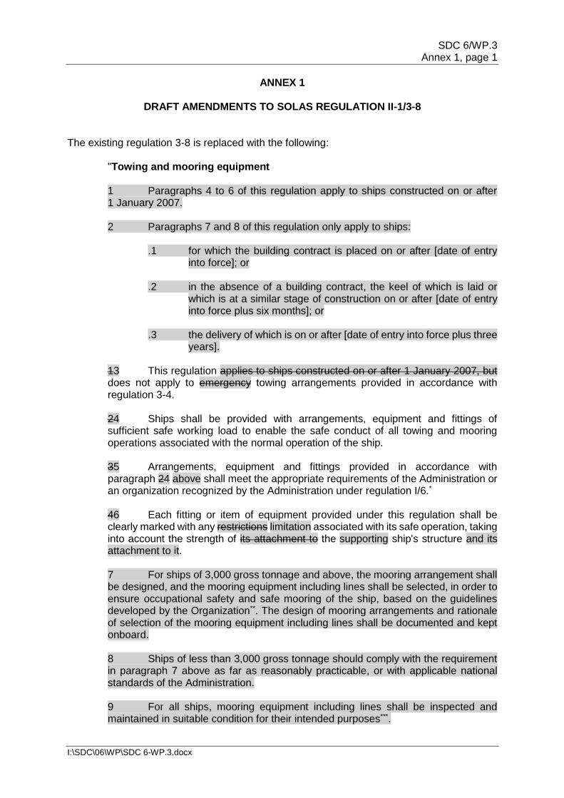
1 Paragraphs 4 to 6 of this regulation apply to ships constructed on or after 1 January 2007. 2 Paragraphs 7 and 8 of this regulation only apply to ships:
.1 for which the building contract is placed on or after [date of entry into force]; or
.2 in the absence of a building contract, the keel of which is laid or
which is at a similar stage of construction on or after [date of entry into force plus six months]; or
.3 the delivery of which is on or after [date of entry into force plus three
years]. 13 This regulation applies to ships constructed on or after 1 January 2007, but does not apply to emergency towing arrangements provided in accordance with regulation 3-4. 24 Ships shall be provided with arrangements, equipment and fittings of sufficient safe working load to enable the safe conduct of all towing and mooring operations associated with the normal operation of the ship. 35 Arrangements, equipment and fittings provided in accordance with paragraph 24 above shall meet the appropriate requirements of the Administration or an organization recognized by the Administration under regulation I/6.* 46 Each fitting or item of equipment provided under this regulation shall be clearly marked with any restrictions limitation associated with its safe operation, taking into account the strength of its attachment to the supporting ship's structure and its attachment to it. 7 For ships of 3,000 gross tonnage and above, the mooring arrangement shall be designed, and the mooring equipment including lines shall be selected, in order to ensure occupational safety and safe mooring of the ship, based on the guidelines developed by the Organization**. The design of mooring arrangements and rationale of selection of the mooring equipment including lines shall be documented and kept onboard. 8 Ships of less than 3,000 gross tonnage should comply with the requirement in paragraph 7 above as far as reasonably practicable, or with applicable national standards of the Administration. 9 For all ships, mooring equipment including lines shall be inspected and maintained in suitable condition for their intended purposes***.
SDC 6/WP.3 Annex 1, page 2
I:\SDC\06\WP\SDC 6-WP.3.docx
__________________
* Refer to the Guidance on shipboard towing and mooring equipment (MSC.1/Circ.1175)
for ships constructed on or after 1 January 2007 but before [date of entry into force] and the Guidance on shipboard towing and mooring equipment (MSC.1/Circ.1175/Rev.1) for the ships constructed on or after [date of entry into force].
** Refer to the Guidelines on the design of mooring arrangements and the selection of appropriate mooring equipment and fittings for safe mooring (MSC.1/Circ.[…]).
*** [Refer to the Guidelines for inspection and maintenance of mooring equipment including lines (MSC.1/Circ.[…])
SDC 6/WP.3 Annex 1, page 3
I:\SDC\06\WP\SDC 6-WP.3.docx
APPENDIX
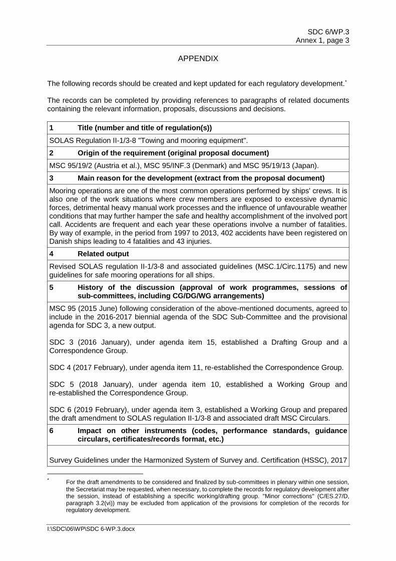
The following records should be created and kept updated for each regulatory development.* The records can be completed by providing references to paragraphs of related documents containing the relevant information, proposals, discussions and decisions.
1 Title (number and title of regulation(s))
SOLAS Regulation II-1/3-8 "Towing and mooring equipment".
2 Origin of the requirement (original proposal document)
MSC 95/19/2 (Austria et al.), MSC 95/INF.3 (Denmark) and MSC 95/19/13 (Japan).
3 Main reason for the development (extract from the proposal document)
Mooring operations are one of the most common operations performed by ships' crews. It is also one of the work situations where crew members are exposed to excessive dynamic forces, detrimental heavy manual work processes and the influence of unfavourable weather conditions that may further hamper the safe and healthy accomplishment of the involved port call. Accidents are frequent and each year these operations involve a number of fatalities. By way of example, in the period from 1997 to 2013, 402 accidents have been registered on Danish ships leading to 4 fatalities and 43 injuries.
4 Related output
Revised SOLAS regulation II-1/3-8 and associated guidelines (MSC.1/Circ.1175) and new guidelines for safe mooring operations for all ships.
5 History of the discussion (approval of work programmes, sessions of sub-committees, including CG/DG/WG arrangements)
MSC 95 (2015 June) following consideration of the above-mentioned documents, agreed to include in the 2016-2017 biennial agenda of the SDC Sub-Committee and the provisional agenda for SDC 3, a new output. SDC 3 (2016 January), under agenda item 15, established a Drafting Group and a Correspondence Group. SDC 4 (2017 February), under agenda item 11, re-established the Correspondence Group. SDC 5 (2018 January), under agenda item 10, established a Working Group and re-established the Correspondence Group. SDC 6 (2019 February), under agenda item 3, established a Working Group and prepared the draft amendment to SOLAS regulation II-1/3-8 and associated draft MSC Circulars.
6 Impact on other instruments (codes, performance standards, guidance circulars, certificates/records format, etc.)
Survey Guidelines under the Harmonized System of Survey and. Certification (HSSC), 2017
* For the draft amendments to be considered and finalized by sub-committees in plenary within one session,
the Secretariat may be requested, when necessary, to complete the records for regulatory development after the session, instead of establishing a specific working/drafting group. "Minor corrections" (C/ES.27/D, paragraph 3.2(vi)) may be excluded from application of the provisions for completion of the records for regulatory development.
SDC 6/WP.3 Annex 1, page 4
I:\SDC\06\WP\SDC 6-WP.3.docx
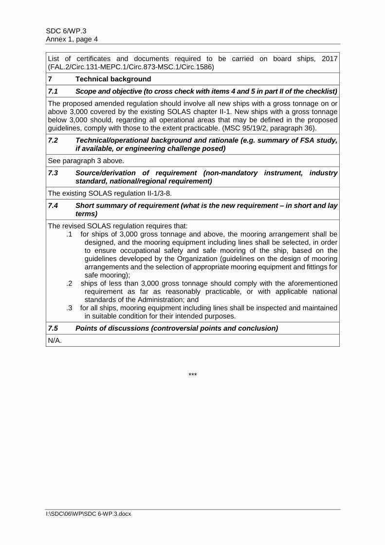
List of certificates and documents required to be carried on board ships, 2017 (FAL.2/Circ.131-MEPC.1/Circ.873-MSC.1/Circ.1586)
7 Technical background
7.1 Scope and objective (to cross check with items 4 and 5 in part II of the checklist)
The proposed amended regulation should involve all new ships with a gross tonnage on or above 3,000 covered by the existing SOLAS chapter II-1. New ships with a gross tonnage below 3,000 should, regarding all operational areas that may be defined in the proposed guidelines, comply with those to the extent practicable. (MSC 95/19/2, paragraph 36).
7.2 Technical/operational background and rationale (e.g. summary of FSA study, if available, or engineering challenge posed)
See paragraph 3 above.
7.3 Source/derivation of requirement (non-mandatory instrument, industry standard, national/regional requirement)
The existing SOLAS regulation II-1/3-8.
7.4 Short summary of requirement (what is the new requirement – in short and lay terms)
The revised SOLAS regulation requires that: .1 for ships of 3,000 gross tonnage and above, the mooring arrangement shall be
designed, and the mooring equipment including lines shall be selected, in order to ensure occupational safety and safe mooring of the ship, based on the guidelines developed by the Organization (guidelines on the design of mooring arrangements and the selection of appropriate mooring equipment and fittings for safe mooring);
.2 ships of less than 3,000 gross tonnage should comply with the aforementioned requirement as far as reasonably practicable, or with applicable national standards of the Administration; and
.3 for all ships, mooring equipment including lines shall be inspected and maintained in suitable condition for their intended purposes.
7.5 Points of discussions (controversial points and conclusion)
N/A.
***
SDC 6/WP.3 Annex 2, page 1
I:\SDC\06\WP\SDC 6-WP.3.docx
ANNEX 2
DRAFT MSC CIRCULAR
GUIDELINES ON THE DESIGN OF MOORING ARRANGEMENTS AND THE SELECTION OF APPROPRIATE MOORING EQUIPMENT
AND FITTINGS FOR SAFE MOORING 1 The Maritime Safety Committee, at its […] session ([…]), having considered a proposal by the Sub-Committee on Ship Design and Construction, at its […] session, and recognizing the importance of design of mooring arrangements and the selection of appropriate mooring equipment and fittings for safe mooring operations, with a view to ensuring a uniform approach towards the application of the provisions of SOLAS regulation II 1/3-8, as amended by resolution […] which is expected to become effective on [date of entry into force], approved the Guidelines on the design of mooring arrangements and the selection of appropriate mooring equipment and fittings for safe mooring, as set out in the annex. 2 Member States are invited to bring the annexed Guidelines to the attention of ship designers, shipyards, shipowners, ship managers, bareboat charterers and other organizations or persons responsible for design of mooring arrangements and the selection of appropriate mooring equipment and fittings. 3 Member States are also invited to bring the annexed Guidelines to the attention of shipmasters, ships' officers and crew and all other parties concerned.
SDC 6/WP.3 Annex 2, page 2
I:\SDC\06\WP\SDC 6-WP.3.docx
ANNEX
DRAFT GUIDELINES ON THE DESIGN OF MOORING ARRANGEMENTS AND THE SELECTION OF APPROPRIATE MOORING EQUIPMENT
AND FITTINGS FOR SAFE MOORING 1 Introduction 1.1 Historical evolution in ship designs, especially the design of large ships have resulted in optimized performance and a greater degree of complexity; this has not been extended to the design of ships' mooring arrangements. These Guidelines support the application of the provisions of SOLAS for mooring arrangements and encourage greater consideration of the occupational safety and safe mooring of the ship when designing new ships. Improving the design of mooring arrangements should enhance usability and safety during towing and mooring operations. 1.2 Regulations II-1/3-8.7 and II-1/3-8.8 of the International Convention for the Safety of Life at Sea (SOLAS), as amended, requires that for ships of 3,000 gross tonnage and above constructed on or after [1 January 2024], the mooring arrangement shall be designed, and the mooring equipment including lines shall be selected, in order to ensure occupational safety and safe mooring of the ship; and ships of less than 3,000 gross tonnage constructed on or after [1 January 2024] should comply with these requirements as far as reasonably practicable, or with applicable national standards of the Administration. 1.3 These Guidelines provide an approach to the design of mooring arrangements, and the selection of mooring equipment and fittings, which should be applied in conjunction with principles of ergonomics and usability. 2 Definitions For the purposes of these Guidelines: 2.1 Line Design Break Force (LDBF) means the minimum force that a new, dry, spliced, mooring line will break at. This is for all synthetic cordage materials. 2.2 Mooring area refers to the dedicated area on a ship where mooring equipment is installed and line-handling takes place. It also includes areas where there is a risk of personnel injury in event of snap-back or other failure of mooring equipment. There may be multiple mooring areas on a ship. 2.3 Mooring arrangements means the configuration of the mooring equipment and fittings and other design features of the ships related to the mooring operation, i.e. lighting and communication equipment. 2.4 Mooring equipment and fittings means items such as mooring winches, capstans, bollards, bitts, fairleads, rollers, chocks, etc. and also includes mooring lines. 2.5 Mooring lines means ropes, wires and combinations used for mooring operations other than messenger lines but including tails. 2.6 Mooring operations means normal mooring and unmooring of the ship, including associated in-harbour towing movements.
SDC 6/WP.3 Annex 2, page 3
I:\SDC\06\WP\SDC 6-WP.3.docx
2.7 Mooring personnel means personnel tasked to assist in the activity of mooring and unmooring ships, either ashore or from mooring boats, carried out within the framework of port marine services. 2.8 Shipboard personnel means personnel assigned duties for supervising or working in mooring areas during mooring operations. 2.9 Ship Design Minimum Breaking Load (MBLSD) means the minimum breaking load of new, dry, mooring lines for which shipboard fittings and supporting hull structures are designed in order to meet mooring restraint requirements. 2.10 Supervising personnel means shipboard personnel assigned duties for supervising mooring areas during mooring operations. 2.11 Towing and mooring arrangements plan means the plan as described in section 5 of the annex to the Revised guidance on shipboard towing and mooring equipment (MSC.1/Circ.1175/Rev.1) ("Revised guidance"). This plan presents specific information regarding the towing and mooring fittings aboard the vessel, the mooring lines, as well as the arrangement of mooring lines and the acceptable environmental conditions for mooring. 2.12 Working Load Limit (WLL) means the maximum load that a mooring line should be subjected to in operational service, calculated from the relevant environmental mooring restraint requirement. 3 Goals The equipment selection and mooring arrangement design safety objectives should be to facilitate safe mooring operations and reduce the risk to shipboard personnel and mooring personnel caused by inappropriate selection and arrangement of equipment and fittings. 4 Functional objectives A ship should be provided with mooring equipment and fittings appropriate for its type and size. In addition, a ship should be provided with mooring lines appropriate for the equipment and fittings installed on board. In order to achieve the goals for the correct equipment selection and mooring arrangement design safety objectives set out in section 3, the following functional objectives should be applied. Mooring equipment and fittings should be:
.1 arranged to minimize obstructed access to and operation of the mooring equipment;
.2 arranged to minimize obstructed access to working space, and minimize
obstructed view of the mooring area; .3 arranged to minimize the need for complex mooring line configurations
during the normal operation of the ship; .4 selected and arranged to minimize the need for manual handling of mooring
lines under load; and .5 selected and arranged to minimize the exposure of personnel involved in
mooring operations to the dynamic loads of mooring lines.
SDC 6/WP.3 Annex 2, page 4
I:\SDC\06\WP\SDC 6-WP.3.docx
5 Achievement of the functional objectives To meet the functional objectives, the following design and equipment features should be considered from the earliest stage in the design process. Selection of equipment, fittings and mooring lines should not be undertaken independently. To facilitate safe mooring operations, it is necessary for mooring equipment, fittings and mooring lines to be considered as a complete system within which all components are compatible. The guidance on the design of mooring arrangements and the selection of equipment and fittings should be read in conjunction with the [Revised] guidance on shipboard towing and mooring equipment (MSC.1/Circ.1175/Rev.1). This section should be implemented to the extent permitted by the size and purpose of the ship. 5.1 Design of mooring arrangements 5.1.1 To minimize the need for complex mooring line configurations during the normal operation of the ship, mooring winches and fairleads should be positioned to allow the use of direct, unobstructed leads from the mooring winch to the fairlead for each of the mooring lines described in the towing and mooring arrangements plan. It is preferable to provide a dedicated fairlead for each mooring line. 5.1.2 Where a straight lead is not possible:
.1 the deviation from a straight lead should be by means of pedestal fairleads, rolling fairleads or similar means that will reduce friction between line/fitting and reduce bend losses. Steel fittings such as horns or bollards without chafe protection should be avoided;
.2 the line should traverse the mooring area from winch to the fairlead by the
shortest route; and .3 changes of direction of mooring line should be minimized to prevent
reductions in mooring line strength due to bend loss and introduction of complex snap-back areas.
5.1.3 To provide for the oversight and supervision of the mooring operations, the mooring area should be designed to give supervising personnel an unobstructed view of the installed mooring equipment and fittings. This should include the provision for a platform, or other appropriate means, by which supervising personnel can obtain an unobstructed view of the mooring area and berth arrangements planned to be used from a position clear of hazards.
5.1.4 The mooring arrangements should be designed to provide unobstructed views between shipboard personnel, and of lines being worked, within the mooring area.
5.1.5 The winch operator should be provided with mooring winch controls that are positioned so that the winch operator has a direct view of the line in the mooring area being worked without stepping away from the winch controls. Winch controls should be positioned clear of hazards.
5.1.6 Deck illumination should provide a clear view of the mooring area and the equipment and lines being worked during hours of darkness or in conditions of limited visibility.
SDC 6/WP.3 Annex 2, page 5
I:\SDC\06\WP\SDC 6-WP.3.docx
5.1.7 The design of mooring arrangements and mooring areas should take into account the following constraints:
.1 anticipated variations in shore-based mooring arrangements and the need to preserve flexibility in mooring line configurations to achieve an appropriate restraining capacity;
.2 ships' structural elements, including accommodation, ventilation exhausts, cargo equipment or similar obstacles, on access; and
.3 special requirements for the location and selection of mooring equipment and fittings, for example special requirements for canal transits.
5.1.8 Unless the size and special features of the ship do not permit it, equipment and fittings in mooring areas should be positioned to provide shipboard personnel with unobstructed access to the following during mooring operations:
.1 mooring winches and winch controls;
.2 mooring fittings;
.3 mooring lines and mooring line stowage; and
.4 the space between shipside fairleads and winches to permit mooring personnel to safely apply stoppers to mooring lines when necessary.
5.1.9 The mooring arrangements should be designed to avoid the exposure of the shipboard personnel to lines under tension through snap-back or sudden movements of mooring lines. In this respect the following measures should be considered:
.1 locate winches close to shipside fairleads. The position of winches should not result in inappropriate mooring line orientations, or block or otherwise interfere with the use of shipside fairleads for additional mooring lines, connecting up of tugs for towage during mooring operations or the ability to safely moor the ship;
.2 enclosing the mooring line(s) behind barrier(s) provided that such enclosures
do not adversely affect the performance of the mooring system and do not prevent effective inspection and maintenance of equipment, fittings and mooring lines;
.3 alternative design(s) where crew members do not need to work close to or
have to pass mooring lines under tension or potentially under tension; .4 use of appropriate, alternative means to moor the ship, including but not
limited to automated mooring systems; or .5 permanently fix mooring lines to a mooring winch.
5.1.10 Mooring areas should be considered as potential snap-back zones and signage should be provided to indicate that this is the case. 5.1.11 To minimize the need for manual handling of towing and mooring lines, the following measures should be considered:
SDC 6/WP.3 Annex 2, page 6
I:\SDC\06\WP\SDC 6-WP.3.docx
.1 equipment and fitting arrangements should minimize the distance over which any mooring line may need to be handled;
.2 the use of fixed or dedicated mooring lines, taking into account the need to
avoid inappropriate mooring line orientations, or block or otherwise interfere with the use of shipside fairleads for additional mooring lines, connecting up of tugs for towage during mooring operations or the ability to safely moor the ship;
.3 the layout to be designed to prevent manual intervention in transfer of the
mooring line from storage drum to mooring winch drum and vice versa; .4 use of spooling equipment; .5 additional mooring lines should be available for immediate use, provided that
their stowage does not interfere with the safe operation of the mooring equipment; and
.6 a sufficient number of mooring winches so that, during mooring operations,
manual use of warping ends, stoppers, capstans and bitts is minimized, as far as possible.
5.1.12 The mooring arrangement design should take into account the principles for effective mooring arrangements included in appropriate industry guidance on mooring equipment and fittings. 5.2 Selection of equipment, fittings and mooring lines 5.2.1 The selection of winches should take into account:
.1 the availability of winches with alternative drum arrangements, including split drum arrangements, which can reduce the need for manual handling of mooring lines during mooring operations;
.2 the positioning of winch controls, including the availability of remote controls
for winches to improve the line of sight and reduce operator exposure to snap-back;
.3 the availability of constant tension winches and their appropriateness for the
normal operation of the ship; and .4 limiting noise levels to ensure proper communication during mooring
operations. 5.2.2 The selection of fittings should take into account:
.1 the type of mooring line with which the fitting is designed to be used. The design or selection of the fitting and the design of its hull supporting structure should be done in accordance with MSC.1/Circ.1175/Rev.1;
.2 the diameter D of surfaces of mooring fittings that are in contact with the
mooring line in relation to the mooring line diameter d (D/d ratio) to reduce or mitigate bend loss of strength; and
SDC 6/WP.3 Annex 2, page 7
I:\SDC\06\WP\SDC 6-WP.3.docx
.3 the need for the load-bearing surfaces of fittings to minimize damage from chafing and abrasion.
5.2.3 The selection of mooring lines should take into account:
.1 the guidance on mooring restraint as per appendix A of MSC.1/Circ.1175/Rev.1;
.2 the diameter D of surfaces of mooring fittings that are in contact with the
mooring line in relation to the mooring line diameter d (D/d ratio) to reduce or mitigate bend loss of strength;
.3 the compatibility of the MBLSD of mooring lines and the brake capacity of the
mooring winches installed on board; .4 the Line Design Break Force (LDBF) to be 100% to 105% of the MBLSD; .5 the characteristics and limitations of mooring lines including material
properties and environmental operating conditions anticipated during normal operation of the ship;
.6 the anticipated behaviour of the mooring line in the event of failure;
.7 the influence on stored energy and the potential for snap-back of high stiffness mooring lines caused by the use of tails; and
.8 as far as possible, but at least for lines in the same service, (e.g. headlines, breast lines or springs), mooring lines of the same diameter and type (i.e. material) should be used.
5.2.4 To avoid overload on mooring winches, fittings and mooring lines, consideration should be given to select mooring winches with brake capacity of less than the ship design minimum breaking load of the mooring line or with adjustable brake capacity. 5.2.5 Fittings, particularly shipside fairleads, should be positioned to minimize the potential for chafing of mooring lines during the normal operation of the ship. 5.2.6 The selection of equipment and fittings including lines should take into account the principles for effective mooring arrangements included in appropriate industry guidance. 5.2.7 The mooring equipment, fittings and the mooring lines should at all times be compatible in design, diameter, strength, suitability, etc. and maintained with the original purpose and concept of the mooring arrangement. 5.2.8 Load limits 5.2.8.1 Notwithstanding the definitions in paragraph 2.1, LDBF of mooring lines made of nylon should be tested under wet and spliced conditions.
5.2.8.2 All components of a ship's mooring system, within defined tolerances, should be selected based on MBLSD.
5.2.8.3 When selecting lines, the LDBF should be 100% to 105% of the MBLSD.
SDC 6/WP.3 Annex 2, page 8
I:\SDC\06\WP\SDC 6-WP.3.docx
5.2.8.4 The WLL of mooring lines should be used as user operating limiting values, not to be exceeded. The WLL is expressed as a percentage of MBLSD and should be used as a limiting value in operational mooring analyses. Steel wires have a WLL of 55% of MBLSD and all other cordage (synthetic) have a WLL of 50% of the MBLSD.
6 Documentation on deviation 6.1 A supplement to the "Towing and mooring arrangements plan" should record the deviations if any, in relation to the following paragraphs:
.1 5.1.2 (where a straight lead is not possible); .2 5.1.4 (unobstructed views); .3 5.1.5 (protection of winch operators); .4 5.1.8 (access to mooring equipment and fitting); .5 5.1.9 (exposure of the shipboard personnel to lines under tension); and .6 5.1.11 (minimize the need for manual handling of towing and mooring lines).
6.2 The documentation should include justification for such deviations and suitable safety measures, if any. 6.3 A reference to the supplement should be included in the towing and mooring arrangement plan so as to make the shipboard personnel aware of the safety measures which needs to be considered during mooring operations. 7 Reference 1 Oil Companies International Marine Forum (OCIMF), Mooring Equipment Guidelines, 4th Edition 2018, ISBN: 978-1-85609-771-0. 2 Ian. C. Clark BSc, MSc, Master Mariner, MNI, The Nautical Institute, Mooring and Anchoring Ships Vol.1, Principle and Practice, ISBN: 9781906915934, 2009.
***
SDC 6/WP.3 Annex 3, page 1
I:\SDC\06\WP\SDC 6-WP.3.docx
ANNEX 3
DRAFT MSC CIRCULAR
GUIDELINES FOR INSPECTION AND MAINTENANCE OF MOORING EQUIPMENT INCLUDING LINES
1 The Maritime Safety Committee, at its […] session ([…]), having considered a proposal by the Sub-Committee on Ship Design and Construction, at its […] session, and recognizing the importance of inspection and maintenance of mooring equipment including lines, approved the Guidelines for inspection and maintenance of mooring equipment including lines, as set out in the annex. 2 Member States are invited to bring the annexed Guidelines to the attention of shipowners, ship managers, bareboat charterers and other organizations or persons responsible for operation of ships. 3 Member States are also invited to bring the annexed Guidelines to the attention of shipmasters, ships' officers and crew and all other parties concerned, for providing guidance on inspection and maintenance of mooring equipment including mooring lines.
SDC 6/WP.3 Annex 3, page 2
I:\SDC\06\WP\SDC 6-WP.3.docx
ANNEX
GUIDELINES FOR INSPECTION AND MAINTENANCE OF MOORING EQUIPMENT INCLUDING LINES
1 General 1.1 Purpose The purpose of these Guidelines is to provide recommendations and guidance for maintenance and in-service inspections of mooring equipment including lines and tails, criteria for identifying worn-out lines and tails for removal from service before failure, and criteria for selection of replacement mooring lines and tails. 1.2 Application These Guidelines apply to all ships. Certain provisions are intended for reference by shipboard personnel, and other provisions are intended for Company personnel responsible for selecting and procuring replacement mooring lines. 2 Definitions For the purpose of these Guidelines: 2.1 Bend radius (D/d ratio) means the diameter, D, of a mooring fitting divided by the diameter, d, of a mooring line that is led around or through the fitting. The D/d ratio is used by mooring line manufacturers to specify the minimum radius of a fitting around or through which a mooring line of diameter "d" should be led, in order to reduce or mitigate bend loss of strength of the mooring line. 2.2 Company means company, as defined in SOLAS regulation IX/1.2. 2.3 Line Design Break Force (LDBF) means the minimum force that a new, dry, spliced, mooring line will break at. This is for all synthetic cordage materials. 2.4 Mooring arrangement means the configuration of the mooring equipment and fittings and other design features of the ship related to the mooring operation, i.e. lighting and communication equipment. 2.5 Mooring boat means the boat handling mooring lines between the ship and ashore mooring facilities during mooring and unmooring operations and does not include harbour ship assist tugs (see FAL.6/Circ.11/Rev.1). 2.6 Mooring equipment and fittings means items such as winches, capstans, bollards, bitts, fairleads, rollers, chocks, etc. and also includes mooring lines. 2.7 Mooring line configuration means all components of an individual mooring line, including tails, eye splices, etc. Any change or replacement of a component is a change to the line's configuration, unless a component is replaced by a part having the same specification as in the original configuration. 2.8 Mooring operations means normal mooring and unmooring of the ship, including associated in-harbour towing movements.
SDC 6/WP.3 Annex 3, page 3
I:\SDC\06\WP\SDC 6-WP.3.docx
2.9 Mooring personnel means personnel tasked to assist in the activity of mooring and unmooring ships, either ashore or from mooring boats, carried out within the framework of port marine services. 2.10 Rotation of mooring lines means periodical change of mooring lines for respective mooring drums to equalize the wear of mooring lines. 2.11 Ship Design Minimum Breaking Load (MBLSD) means the minimum breaking load of new, dry, mooring lines for which shipboard fittings and supporting hull structures are designed in order to meet mooring restraint requirements. 2.12 Towing and mooring arrangements plan means the plan as described in section 5 of the annex to MSC.1/Circ.1175/Rev.1. This plan presents specific information regarding the towing and mooring fittings aboard the vessel, the mooring lines, as well as the arrangement of mooring lines and the acceptable environmental conditions for mooring. 3 Safe use of mooring equipment 3.1 Safe use of mooring equipment and fittings Throughout its operational life, mooring equipment should be maintained and operated in accordance with the original design concept, if available, including when replacing parts and lines. In order to ensure all mooring equipment functions as designed, the Company should establish procedures for mooring operations, inspection and maintenance of mooring equipment, including mooring lines, taking into account appropriate references listed in paragraph 7 of these Guidelines. 3.2 Protection and storage of mooring line To preserve the design life of mooring lines, the following practices should be followed during mooring operations:
.1 smooth contacts at turnoff points with large angles and/or eye splices; and .2 using covers/mats at ship side to protect against any friction damage.
3.3 Control of mooring lines 3.3.1 The Company should establish procedures to allow the identification and control of mooring lines, tails and associated attachments when on board and to facilitate inspection and maintenance of mooring lines. Such procedures should include:
.1 providing a means of recording the number, type and location of mooring lines, tails and associated attachments. Such records may be included in either the towing and mooring arrangements plan or with records of inspection and maintenance or an alternative established by the requirements of the Company; and
.2 providing a means of linking specific mooring lines, tails and associated
attachments to the relevant records and a manufacturer's certificate, if available.
3.3.2 Any defect discovered to the mooring lines during mooring operations should be immediately reported to the Master by all parties concerned including shore-based mooring personnel. If no actions are taken as appropriate the competent authorities should be informed, as necessary.
SDC 6/WP.3 Annex 3, page 4
I:\SDC\06\WP\SDC 6-WP.3.docx
4 Inspection and maintenance of mooring lines 4.1 Inspection of mooring lines 4.1.1 To prevent the deterioration of mooring lines to a condition which may result in the failure of the line during mooring operations, the periodic inspection of mooring lines, mooring line tails and associated attachments should be included in the onboard maintenance plan or equivalent maintenance management system. The maintenance plan may be computer based. 4.1.2 The requirements for inspection of individual mooring lines will be specific to the type of mooring line used on board. In general, onboard inspection of mooring lines will be based on manufacturer recommendations and by visual inspection of the outside of the mooring line to identify excessive wear or damage, e.g. external abrasion, external cut, kink, heat damage such as fusion and slackening or fraying of eye splices. Such visual inspections should be based on:
.1 the recommendations of the mooring line and/or tail manufacturer, particularly the criteria provided for the assessment of mooring line condition;
.2 operational experience regarding the performance of the mooring line and/or
mooring line tail during previous mooring operations; and .3 the environmental conditions to which the mooring lines and/or mooring line
tails are routinely exposed. 4.1.3 In the case of jacketed synthetic fibre mooring lines, detailed visual inspection of the condition of the synthetic fibre line may not be possible. The condition of the external jacket is not an accurate indicator of the condition of the load-bearing synthetic fibre material within the mooring line. 4.2 Maintenance of mooring lines The Company should establish the maintenance procedures as required in paragraph 3.1.1 of these Guidelines. The maintenance procedures should specify replacement of in-service mooring lines and may include the rotation of mooring lines. 4.3 Criteria for condemning worn-out mooring lines 4.3.1 The replacement of in-service mooring lines which have been assessed as no longer suitable for use should be based on the removal prior to failure and in accordance with criteria provided by the manufacturer. 4.3.2 For visual inspection and replacement of mooring lines, additional advice is provided in industry guidance on mooring line and mooring line tail inspections. 4.4 Inspection and maintenance of equipment and fittings 4.4.1 Equipment and fittings should be properly inspected and maintained, based on the manufacturer's recommendations. Mooring equipment and fittings should be included in the onboard maintenance plan or equivalent maintenance management system. The maintenance plan may be computer based. 4.4.2 Maintenance should include the preservation, by appropriate means, of the clear marking of information on equipment and fittings, including SWL and winch control instructions.
SDC 6/WP.3 Annex 3, page 5
I:\SDC\06\WP\SDC 6-WP.3.docx
4.4.3 Records of inspection and maintenance of equipment and fittings should be available on board. 4.4.4 Records of the original design concept, equipment, arrangement and specifications should be retained on board through the lifecycle of the ship. 4.4.5 To preserve the design life of mooring lines and reduce the potential for failure during mooring operations any storage provided for additional (loose) mooring lines should minimize the exposure to harmful environments (e.g. UV light, water, chemicals, cargo, extreme temperature). 5 Selection of replacement mooring lines 5.1 When replacing mooring lines, compatibility with the mooring equipment and fittings on board, as specified in the mooring arrangement plan, should be taken into account. This should be achieved by selecting a replacement mooring line which meets the designed specifications. In cases where this is not possible, the following properties should be taken into consideration and the towing and mooring arrangement plan updated accordingly:
.1 breaking strength; .2 environmental conditions to be used (e.g. temperature); .3 linear density; .4 tenacity; .5 D/d ratios; .6 compression fatigue; and .7 stiffness.
5.2 Any increase in LDBF (Line Design Breaking Force) for the mooring lines above the limits specified, i.e. 100% to 105% of the MBLSD, may require a review of the operating parameters and load limits of mooring equipment and fitting as well as of their hull supporting structures. 5.3 It should be noted that, when selecting replacement mooring lines, over time in service their strength will decay due to varying environmental conditions and thus the original service life expectations may not be achieved. Therefore, the Company should ensure that the condition of mooring lines is tracked throughout their service with the objective to replace the line before failure. 5.4 For wire ropes, corrosion protection should be considered. 5.5 For both wire and fibre mooring lines, the acceptable minimum bend radius (D/d ratio) recommended by the manufacturer should be taken into consideration as strength and life expectancy of these lines are directly related to the bend radius they are exposed to in service. 5.6 Where the acceptable minimum bend radius recommendations for a particular mooring line are not achievable, the service life of the line may be less than that stated by the manufacturer and therefore the line may need to be replaced before the end of the service life recommended by the manufacturer. The condition of lines regularly exposed to below the acceptable minimum bend radius should be subject to particular attention during inspections.

SDC 6/WP.3 Annex 3, page 6
I:\SDC\06\WP\SDC 6-WP.3.docx
5.7 When selecting replacement mooring lines with high stiffness, including wire and high modulus synthetic lines, consideration should be given to the use of synthetic tails in order to reduce peak loading when the ship is secured alongside. 5.8 Consideration of the use of synthetic tails on high stiffness mooring lines should take into account industry and manufacturer guidance and the potential effects of synthetic tails on the stored energy of mooring lines under tension. The use of tails can change the characteristics of a mooring line and its behaviour in the event of failure. High stiffness mooring lines may exert significant dynamic force and have significant snap-back zones when used with synthetic tails that have a low stiffness. 6 Updating of ship documents and record-keeping 6.1 Records of inspection and maintenance of mooring equipment and inspection and replacement of mooring lines should be retained on board. Such records should be kept for a period determined by the Company, but in any event the records should be kept until completion of the next annual survey. 6.2 Consideration should be given to control and certification of mooring lines, wires, tails and associated attachments. Manufacturer's test certificates for mooring lines, joining shackles and synthetic tails should be kept on board and properly linked back to the equipment. 6.3 The items to be recorded during inspection and maintenance should be determined taking into account the recommendations of the manufacturers of the mooring lines. 6.4 Any change of mooring line configuration requires updating of the towing and mooring arrangements plan. 7 References 1 Oil Companies International Marine Forum (OCIMF), Mooring Equipment Guidelines, 4th Edition 2018, ISBN: 978-1-85609-771-0. 2 Ian. C. Clark BSc, MSc, Master Mariner, MNI, The Nautical Institute, Mooring and Anchoring Ships Vol.1, Principle and Practice, ISBN: 9781906915934, 2009. 3 Walter Vervloesem AMNI, The Nautical Institute, Mooring and Anchoring Ships Vol.2, Inspection and Maintenance, ISBN: 9781870077941, 2009.
***
SDC 6/WP.3 Annex 4, page 1
I:\SDC\06\WP\SDC 6-WP.3.docx
ANNEX 4
DRAFT MSC CIRCULAR
REVISED GUIDANCE ON SHIPBOARD TOWING AND MOORING EQUIPMENT 1 The Maritime Safety Committee, at its eightieth session (11 to 20 May 2005), following the recommendations made by the Sub-Committee on Ship Design and Equipment at its forty-eighth session, approved guidance concerning shipboard equipment, fittings and supporting hull structures associated with towing and mooring, as set out in the annex, with a view to ensuring a uniform approach towards the application of the provisions of for uniform implementation of SOLAS regulation II-1/3-8 adopted by resolution MSC.194(80), which is expected to become became effective on 1 January 2007. 2 The Committee, at its […] session ([…]), having considered a proposal by the Sub-Committee on Ship Design and Construction, at its […] session, with a view to ensuring a uniform approach towards the application of the provisions of SOLAS regulation II-1/3-8, as amended by resolution […] which is expected to become effective on [date of entry into force], approved the revised Guidance on shipboard towing and mooring equipment, as set out in the annex. 3 This revised guidance is applicable to ships constructed on or after [date of entry into force] and does not supersede the Guidance on shipboard towing and mooring equipment (MSC.1/Circ.1175) which remain applicable to ships constructed on or after 1 January 2007 but before [date of entry into force]. 24 Member Governments are invited to use the annexed guidance when applying the revised SOLAS regulation II-1/3-8, and to bring it to the attention of all parties concerned.
SDC 6/WP.3 Annex 4, page 2
I:\SDC\06\WP\SDC 6-WP.3.docx
ANNEX
SHIPBOARD EQUIPMENT, FITTINGS AND SUPPORTING HULL STRUCTURES ASSOCIATED WITH TOWING AND MOORING
1 Application 1.1 Under regulation II-1/3-8 of the 1974 SOLAS Convention, as adopted by resolution MSC.194(80) in 2005 [insert appropriate reference for the pending revision of II-1/3-8], new displacement type ships, except high-speed craft and offshore units, shall be provided with arrangements, equipment and fittings of sufficient safe working load to enable the safe conduct of all towing and mooring operations associated with the normal operations of the ship. The arrangements, equipment and fittings shall meet the appropriate requirements of the Administration or an organization recognized by the Administration. 1.2 The Revised guidance on shipboard towing and mooring equipment (MSC.1/Circ.1175/Rev.1) should apply to ships constructed on or after [date of entry into force]. To ships constructed on or after 1 January 2007 and before [date of entry into force], the Guidance on shipboard towing and mooring equipment (MSC.1/Circ.1175) should apply. 1.23 This circular is intended to provides standards for the design and construction of shipboard fittings and supporting hull structures associated with normal towing and mooring operations in harbours or sheltered waters, which Administrations are recommended to implement. This circular also contains design guidance for fittings of ships that are further intended to be towed by another ship or tug, e.g. in an emergency. The provisions of this guidance do This circular does not require tow lines nor mandate standards for mooring lines onboard the ship. Furthermore, this guidance is not applicable to design and construction of shipboard fittings and supporting hull structures used for special towing services defined as:
.1 Escort towing: Towing service required in some estuaries to control the ship in case of failures of the propulsion or steering system. It should be referred to local escort requirements;
.2 Canal transit towing: Towing service for ships transiting canals, e.g. the
Panama Canal. It should be referred to local canal transit requirements; and .3 Emergency towing for tankers: Towing service to assist tankers in
case of emergency. It should be referred to paragraph 1 of SOLAS regulation II-1/3-4.
1.34 Equipment that is used for both towing and mooring should be in accordance with sections 3 and 4. 2 Definitions For the purpose of this guidance: 2.1 Normal towing means towing operations necessary for manoeuvring in ports and sheltered waters associated with the normal operations of the ship. 2.2 Other towing means towing by another ship or a tug, such as to assist the ship in case of emergency.
SDC 6/WP.3 Annex 4, page 3
I:\SDC\06\WP\SDC 6-WP.3.docx
2.13 Shipboard fittings mean bollards and bitts, fairleads, stand pedestal rollers and chocks used for the normal mooring of the ship and similar components used for the normal or other towing of the ship. Other components such as capstans, winches, etc. are not covered by this guidance. Any weld, bolt or other fastening connecting the shipboard fitting to the supporting hull structure is part of the shipboard fitting and subject to any industry standard applicable to such fitting. 2.24 Supporting hull structure means that part of the ship structure on/in which the shipboard fitting is placed and which is directly submitted to the forces exerted on the shipboard fitting. The hull structure supporting capstans, winches, etc. used for the normal or other towing and mooring operations mentioned above should also be subject to this guidance. 2.35 Industry standard means international or national standards which are recognized in the country where the ship is built, subject to the approval of the Administration. 2.6 Safe working load (SWL) means the safe load limit of shipboard fittings used for mooring operations in harbours or similar sheltered waters. 2.7 Safe towing load (TOW) means the safe load limit of shipboard fittings used for normal and other towing. 2.8 Ship Design Minimum Breaking Load (MBLSD) means the minimum breaking load of new, dry mooring lines for which shipboard fittings and supporting hull structures are designed in order to meet mooring restraint requirements. 3 Towing fittings 3.1 Strength The strength of shipboard fittings used for normal towing operations and their supporting hull structures should comply with the provisions of 3.2 to 3.6. Where a ship is equipped with shipboard fittings intended to be used for other towing services, the strength of these fittings and their supporting hull structures should also comply with these provisions. The strength of shipboard fittings intended to be used for both towing and mooring and of their supporting hull structures should also comply with the provisions of section 4. 3.2 Arrangements Shipboard fittings for towing should be located on longitudinals, beams stiffeners and/or girders which are part of the deck construction so as to facilitate efficient distribution of the towing load. Other equivalent arrangements may be accepted (for Panama chocks, chocks in bulwarks, etc.), provided the strength is confirmed as adequate for the intended service. 3.3 Load considerations 3.3.1 The minimum design load used for applied to supporting hull structures for shipboard fittings should be:
.1 for normal towing operations (e.g. harbour/manoeuvring) should be, 1.25 times the intended maximum towing load (e.g. static bollard pull), as indicated on the towing and mooring arrangements plan. The design load should be applied through the tow line according to the arrangement shown on the towing and mooring arrangements plan.
SDC 6/WP.3 Annex 4, page 4
I:\SDC\06\WP\SDC 6-WP.3.docx
3.3.2 For for other towage towing services (e.g. escort), the design load used for each fitting should be the nominal breaking strength of the tow line defined in table 1 based on the equipment number (EN) described in the appendix. the ship design minimum breaking load of the tow line defined in appendix A;
.3 for fittings intended to be used for both normal and other towing operations,
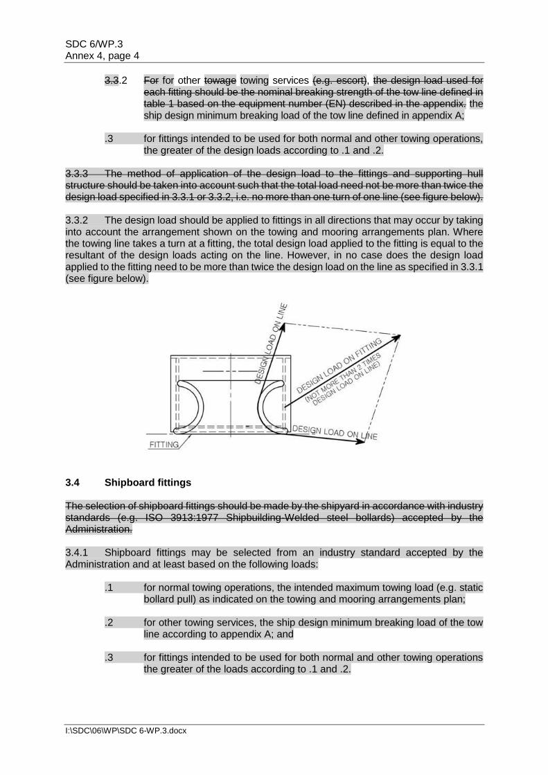
the greater of the design loads according to .1 and .2. 3.3.3 The method of application of the design load to the fittings and supporting hull structure should be taken into account such that the total load need not be more than twice the design load specified in 3.3.1 or 3.3.2, i.e. no more than one turn of one line (see figure below). 3.3.2 The design load should be applied to fittings in all directions that may occur by taking into account the arrangement shown on the towing and mooring arrangements plan. Where the towing line takes a turn at a fitting, the total design load applied to the fitting is equal to the resultant of the design loads acting on the line. However, in no case does the design load applied to the fitting need to be more than twice the design load on the line as specified in 3.3.1 (see figure below).
3.4 Shipboard fittings The selection of shipboard fittings should be made by the shipyard in accordance with industry standards (e.g. ISO 3913:1977 Shipbuilding-Welded steel bollards) accepted by the Administration. 3.4.1 Shipboard fittings may be selected from an industry standard accepted by the Administration and at least based on the following loads:
.1 for normal towing operations, the intended maximum towing load (e.g. static bollard pull) as indicated on the towing and mooring arrangements plan;
.2 for other towing services, the ship design minimum breaking load of the tow
line according to appendix A; and .3 for fittings intended to be used for both normal and other towing operations
the greater of the loads according to .1 and .2.
SDC 6/WP.3 Annex 4, page 5
I:\SDC\06\WP\SDC 6-WP.3.docx
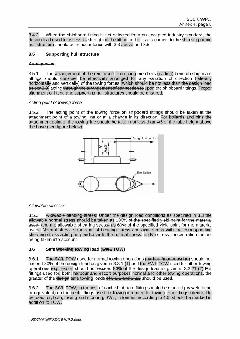
3.4.2 When the shipboard fitting is not selected from an accepted industry standard, the design load used to assess its strength of the fitting and of its attachment to the ship supporting hull structure should be in accordance with 3.3 above and 3.5. 3.5 Supporting hull structure Arrangement 3.5.1 The arrangement of the reinforced reinforcing members (carling) beneath shipboard fittings should consider be effectively arranged for any variation of direction (laterally horizontally and vertically) of the towing forces (which should be not less than the design load as per 3.3) acting through the arrangement of connection to upon the shipboard fittings. Proper alignment of fitting and supporting hull structures should be ensured. Acting point of towing force 3.5.2 The acting point of the towing force on shipboard fittings should be taken at the attachment point of a towing line or at a change in its direction. For bollards and bitts the attachment point of the towing line should be taken not less than 4/5 of the tube height above the base (see figure below).
Allowable stresses 3.5.3 Allowable bending stress: Under the design load conditions as specified in 3.3 the allowable normal stress should be taken as 100% of the specified yield point for the material used; and the allowable shearing stress: as 60% of the specified yield point for the material used;. Normal stress is the sum of bending stress and axial stress with the corresponding shearing stress acting perpendicular to the normal stress. no No stress concentration factors being taken into account. 3.6 Safe working towing load (SWL TOW) 3.6.1 The SWL TOW used for normal towing operations (harbour/manoeuvring) should not exceed 80% of the design load as given in 3.3.1 (1) and the SWL TOW used for other towing operations (e.g. escort should not exceed 80% of the design load as given in 3.3.21 (2) For fittings used for, both, harbour and escort purposes normal and other towing operations, the greater of the design safe towing loads of 3.3.1 and 3.3.2 should be used. 3.6.2 The SWL TOW, in tonnes, of each shipboard fitting should be marked (by weld bead or equivalent) on the deck fittings used for towing intended for towing. For fittings intended to be used for, both, towing and mooring, SWL, in tonnes, according to 4.6, should be marked in addition to TOW.
Design Load on Line
SDC 6/WP.3 Annex 4, page 6
I:\SDC\06\WP\SDC 6-WP.3.docx
3.6.3 The above provisions on SWL TOW apply for a single post basis (no more than one turn of one line) the use of no more than one towing line. 3.6.4 The towing and mooring arrangements plan described in section 5 should define the method of use of towing lines. 4 Mooring fittings 4.1 Strength The strength of shipboard fittings used for mooring operations and of their supporting hull structures as well as the strength of supporting hull structures of winches and capstans should comply with the provisions of 4.2 to 4.6. The strength of shipboard fittings, intended to be used for both, mooring and towing, and of their supporting hull structures, should also comply with the provisions of section 3. 4.2 Arrangements Shipboard fittings, winches and capstans for mooring should be located on longitudinals, beams stiffeners and/or girders, which are part of the deck construction, so as to facilitate efficient distribution of the mooring load. Other equivalent arrangements may be accepted (for Panama chocks in bulwarks, etc.) provided the strength is confirmed adequate for the service. 4.3 Load considerations 4.3.1 The minimum design load applied to shipboard fittings and supporting hull structures should be 1.25 times the breaking strength of the mooring line provided in accordance with table 1 based on the equipment number (EN) described in the appendix. The design load should be applied through the mooring line according to the arrangement shown on the towing and mooring arrangements plan :
.1 of shipboard fittings should be 1.15 times the ship design minimum breaking load of the mooring line provided in accordance with appendix A;
4.3.2 The design load applied to supporting hull structures for winches, etc. should be 1.25 times the breaking strength of the mooring line according to 4.3.1 above and, for capstans, 1.25 times the maximum hauling-in force. The design load should be applied through the mooring line according to the arrangement shown on the towing and mooring arrangements plan. .2 of winches should be 1.25 times the intended maximum brake holding load,
where the maximum brake holding load should be assumed not less than 80% of the ship design minimum breaking load of the mooring line according to appendix A; and
.3 of capstans, 1.25 times the maximum hauling-in force.
4.3.3 The method of application of the design load to the fittings and supporting hull structure should be taken into account such that the total load need not be more than twice the design load specified in 4.3.1, i.e. no more than one turn of one line. 4.3.2 The design load should be applied to fittings in all directions that may occur by taking into account the arrangement shown on the towing and mooring arrangements plan. Where the mooring line takes a turn at a fitting the total design load applied to the fitting is equal to
SDC 6/WP.3 Annex 4, page 7
I:\SDC\06\WP\SDC 6-WP.3.docx
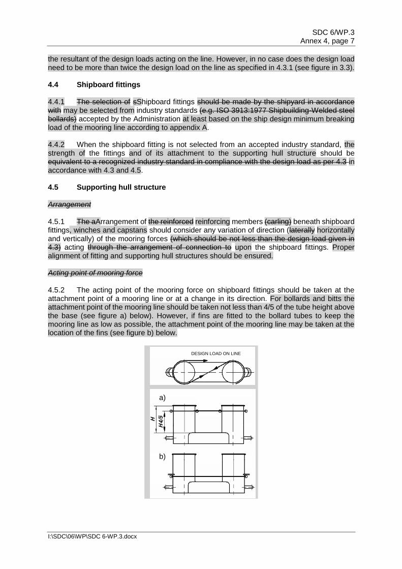
the resultant of the design loads acting on the line. However, in no case does the design load need to be more than twice the design load on the line as specified in 4.3.1 (see figure in 3.3). 4.4 Shipboard fittings 4.4.1 The selection of sShipboard fittings should be made by the shipyard in accordance with may be selected from industry standards (e.g. ISO 3913:1977 Shipbuilding-Welded steel bollards) accepted by the Administration at least based on the ship design minimum breaking load of the mooring line according to appendix A. 4.4.2 When the shipboard fitting is not selected from an accepted industry standard, the strength of the fittings and of its attachment to the supporting hull structure should be equivalent to a recognized industry standard in compliance with the design load as per 4.3 in accordance with 4.3 and 4.5. 4.5 Supporting hull structure Arrangement 4.5.1 The aArrangement of the reinforced reinforcing members (carling) beneath shipboard fittings, winches and capstans should consider any variation of direction (laterally horizontally and vertically) of the mooring forces (which should be not less than the design load given in 4.3) acting through the arrangement of connection to upon the shipboard fittings. Proper alignment of fitting and supporting hull structures should be ensured. Acting point of mooring force 4.5.2 The acting point of the mooring force on shipboard fittings should be taken at the attachment point of a mooring line or at a change in its direction. For bollards and bitts the attachment point of the mooring line should be taken not less than 4/5 of the tube height above the base (see figure a) below). However, if fins are fitted to the bollard tubes to keep the mooring line as low as possible, the attachment point of the mooring line may be taken at the location of the fins (see figure b) below.
DESIGN LOAD ON LINE
a)
b)
SDC 6/WP.3 Annex 4, page 8
I:\SDC\06\WP\SDC 6-WP.3.docx
Allowable stresses 4.5.3 Allowable bending stress: 100% of the specified yield point for the material used; allowable shearing stress: 60% of the specified yield point for the material used; Under the design load conditions, as specified in 4.3, the allowable normal stress should be taken as 100% and the allowable shearing stress as 60% of the specified yield point for the material used. Normal stress is the sum of bending stress and axial stress with the corresponding shearing stress acting perpendicular to the normal stress. nNo stress concentration factors being taken into account. 4.6 Safe working load (SWL) 4.6.1 The SWL should not exceed 80% of the design load given in 4.3. 4.6.1 The SWL, for the purpose of marking, should be equal to the ship design minimum breaking load of the mooring line according to appendix A. 4.6.2 The SWL, in tonnes, of each shipboard fitting should be marked (by weld bead or equivalent) on the deck fittings used intended for mooring. For fittings intended to be used for both mooring and towing, TOW, in tonnes, according to 3.6, should be marked in addition to SWL. 4.6.3 The above provisions on SWL apply for a single post basis (no more than one turn of one line) the use of no more than one mooring line. 4.6.4 The towing and mooring arrangements plan described in section 5 should define the method of use of mooring lines. 5 Towing and mooring arrangements plan 5.1 The SWL and TOW for the intended use for each shipboard fitting should be noted in the towing and mooring arrangements plan available on board for the guidance of the Master. It should be noted that TOW is the load limit for towing purposes and SWL that for mooring purposes. 5.2 Information provided on in the plan should include, in respect of each shipboard fitting:
.1 location on the ship; .2 fitting type; .3 SWL / TOW; .4 purpose (mooring/harbour towing/escort towing, normal towing or other
towing); and .5 method of applying load of towing or mooring line including limiting fleet
angles, i.e. angle of change in direction of a line at the fitting. 5.3 Furthermore, information provided on the plan is to include:
.1 the arrangement of mooring lines showing number of lines (N); .2 the ship design minimum breaking load of each mooring line (MBLSD); .3 the length of each mooring line;
SDC 6/WP.3 Annex 4, page 9
I:\SDC\06\WP\SDC 6-WP.3.docx
.4 restrictions or limitations on the type (including material and construction), stiffness and diameter of mooring lines which are compatible with the mooring equipment and fittings; and
.5 the acceptable environmental conditions as given in appendix A, section 3
for the recommended ship design minimum breaking load of mooring lines for ships with Equipment Number EN > 2000:
.1 30 second mean wind speed from any direction (vW or vW* according
to 3.1.3 or 3.2.2, respectively); and .2 maximum current speed acting on bow or stern (±10°).
Note: When the applied design environmental criteria exceed the above given criteria, information provided in the plan should include the design environmental criteria, similar to the parameters in appendix A:
.1 wind speed and direction; and
.2 current speed and direction.
SDC 6/WP.3 Annex 4, page 10
I:\SDC\06\WP\SDC 6-WP.3.docx
Table 1 APPENDIX A
MOORING AND TOW LINES
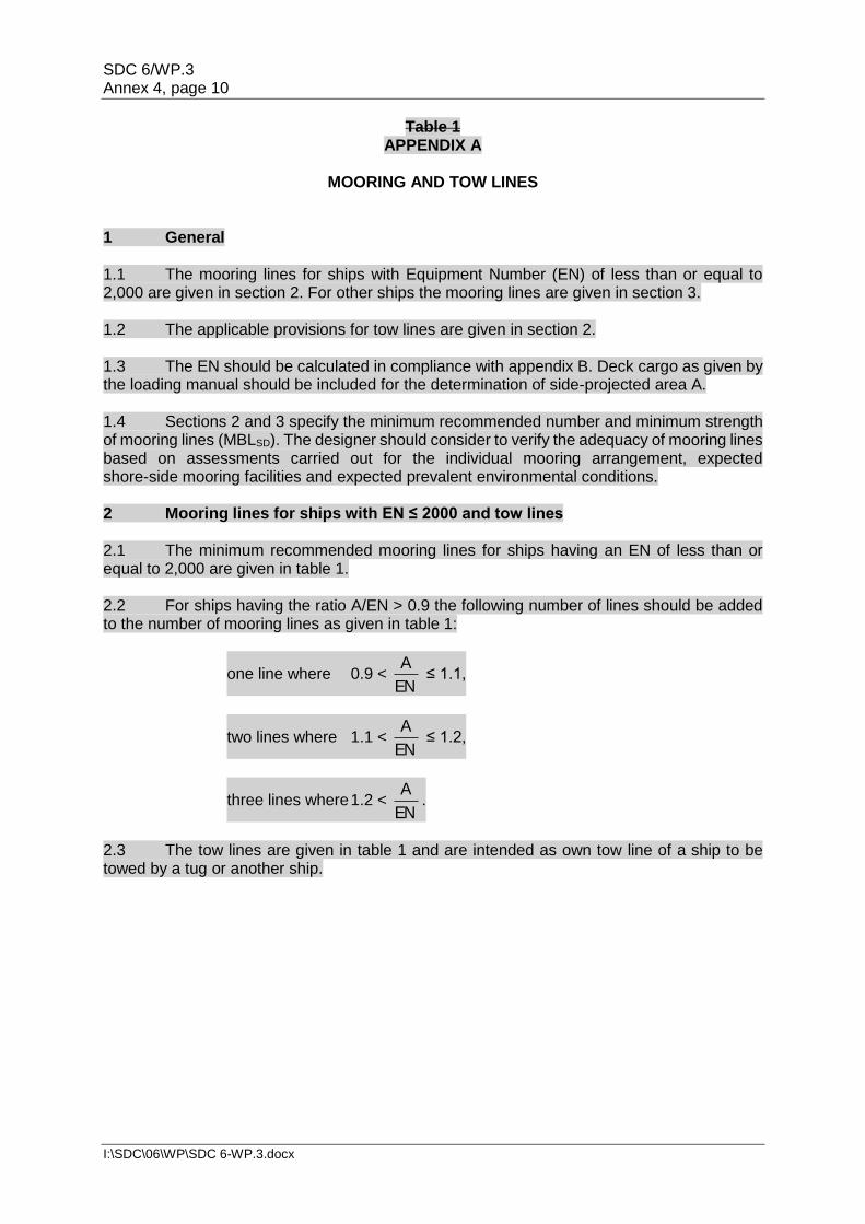
1 General 1.1 The mooring lines for ships with Equipment Number (EN) of less than or equal to 2,000 are given in section 2. For other ships the mooring lines are given in section 3. 1.2 The applicable provisions for tow lines are given in section 2. 1.3 The EN should be calculated in compliance with appendix B. Deck cargo as given by the loading manual should be included for the determination of side-projected area A. 1.4 Sections 2 and 3 specify the minimum recommended number and minimum strength of mooring lines (MBLSD). The designer should consider to verify the adequacy of mooring lines based on assessments carried out for the individual mooring arrangement, expected shore-side mooring facilities and expected prevalent environmental conditions. 2 Mooring lines for ships with EN ≤ 2000 and tow lines 2.1 The minimum recommended mooring lines for ships having an EN of less than or equal to 2,000 are given in table 1. 2.2 For ships having the ratio A/EN > 0.9 the following number of lines should be added to the number of mooring lines as given in table 1:
one line where 0.9 < EN
A ≤ 1.1,
two lines where 1.1 < EN
A ≤ 1.2,
three lines where 1.2 < EN
A.
2.3 The tow lines are given in table 1 and are intended as own tow line of a ship to be towed by a tug or another ship.
SDC 6/WP.3 Annex 4, page 11
I:\SDC\06\WP\SDC 6-WP.3.docx
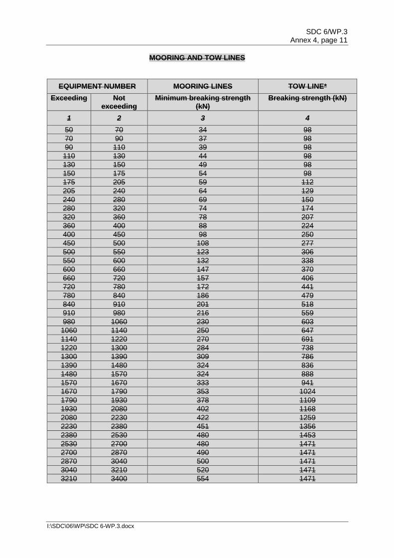
MOORING AND TOW LINES
EQUIPMENT NUMBER MOORING LINES TOW LINE*
Exceeding Not exceeding
Minimum breaking strength (kN)
Breaking strength (kN)
1 2 3 4
50 70 34 98
70 90 37 98
90 110 39 98
110 130 44 98
130 150 49 98
150 175 54 98
175 205 59 112
205 240 64 129
240 280 69 150
280 320 74 174
320 360 78 207
360 400 88 224
400 450 98 250
450 500 108 277
500 550 123 306
550 600 132 338
600 660 147 370
660 720 157 406
720 780 172 441
780 840 186 479
840 910 201 518
910 980 216 559
980 1060 230 603
1060 1140 250 647
1140 1220 270 691
1220 1300 284 738
1300 1390 309 786
1390 1480 324 836
1480 1570 324 888
1570 1670 333 941
1670 1790 353 1024
1790 1930 378 1109
1930 2080 402 1168
2080 2230 422 1259
2230 2380 451 1356
2380 2530 480 1453
2530 2700 480 1471
2700 2870 490 1471
2870 3040 500 1471
3040 3210 520 1471
3210 3400 554 1471
SDC 6/WP.3 Annex 4, page 12
I:\SDC\06\WP\SDC 6-WP.3.docx
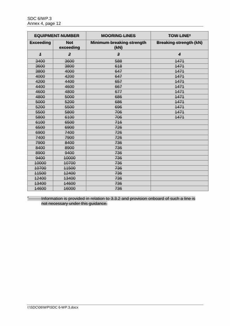
EQUIPMENT NUMBER MOORING LINES TOW LINE*
Exceeding Not exceeding
Minimum breaking strength (kN)
Breaking strength (kN)
1 2 3 4
3400 3600 588 1471
3600 3800 618 1471
3800 4000 647 1471
4000 4200 647 1471
4200 4400 657 1471
4400 4600 667 1471
4600 4800 677 1471
4800 5000 686 1471
5000 5200 686 1471
5200 5500 696 1471
5500 5800 706 1471
5800 6100 706 1471
6100 6500 716
6500 6900 726
6900 7400 726
7400 7900 726
7900 8400 736
8400 8900 736
8900 9400 736
9400 10000 736
10000 10700 736
10700 11500 736
11500 12400 736
12400 13400 736
13400 14600 736
14600 16000 736
* Information is provided in relation to 3.3.2 and provision onboard of such a line is
not necessary under this guidance.
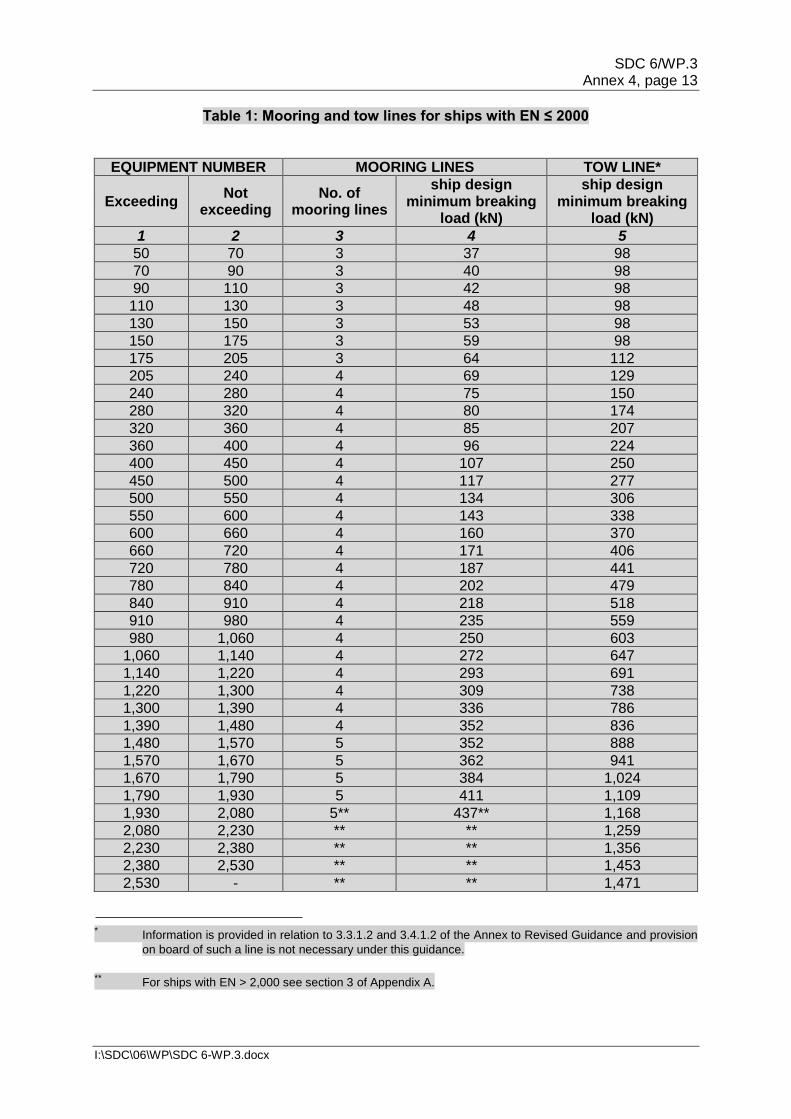
SDC 6/WP.3 Annex 4, page 13
I:\SDC\06\WP\SDC 6-WP.3.docx
Table 1: Mooring and tow lines for ships with EN ≤ 2000
EQUIPMENT NUMBER MOORING LINES TOW LINE*
Exceeding Not
exceeding No. of
mooring lines
ship design minimum breaking
load (kN)
ship design minimum breaking
load (kN)
1 2 3 4 5
50 70 3 37 98
70 90 3 40 98
90 110 3 42 98
110 130 3 48 98
130 150 3 53 98
150 175 3 59 98
175 205 3 64 112
205 240 4 69 129
240 280 4 75 150
280 320 4 80 174
320 360 4 85 207
360 400 4 96 224
400 450 4 107 250
450 500 4 117 277
500 550 4 134 306
550 600 4 143 338
600 660 4 160 370
660 720 4 171 406
720 780 4 187 441
780 840 4 202 479
840 910 4 218 518
910 980 4 235 559
980 1,060 4 250 603
1,060 1,140 4 272 647
1,140 1,220 4 293 691
1,220 1,300 4 309 738
1,300 1,390 4 336 786
1,390 1,480 4 352 836
1,480 1,570 5 352 888
1,570 1,670 5 362 941
1,670 1,790 5 384 1,024
1,790 1,930 5 411 1,109
1,930 2,080 5** 437** 1,168
2,080 2,230 ** ** 1,259
2,230 2,380 ** ** 1,356
2,380 2,530 ** ** 1,453
2,530 - ** ** 1,471
* Information is provided in relation to 3.3.1.2 and 3.4.1.2 of the Annex to Revised Guidance and provision
on board of such a line is not necessary under this guidance.
** For ships with EN > 2,000 see section 3 of Appendix A.
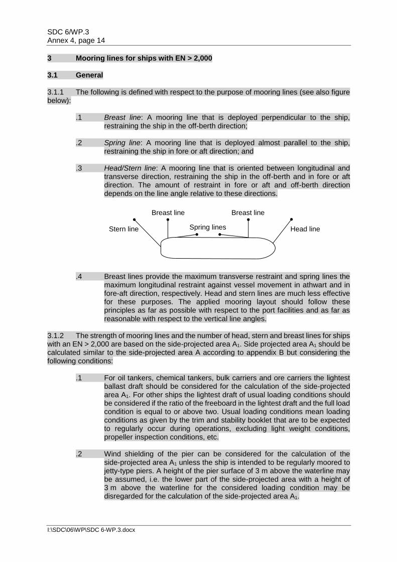
SDC 6/WP.3 Annex 4, page 14
I:\SDC\06\WP\SDC 6-WP.3.docx
3 Mooring lines for ships with EN > 2,000 3.1 General 3.1.1 The following is defined with respect to the purpose of mooring lines (see also figure below):
.1 Breast line: A mooring line that is deployed perpendicular to the ship, restraining the ship in the off-berth direction;
.2 Spring line: A mooring line that is deployed almost parallel to the ship,
restraining the ship in fore or aft direction; and .3 Head/Stern line: A mooring line that is oriented between longitudinal and
transverse direction, restraining the ship in the off-berth and in fore or aft direction. The amount of restraint in fore or aft and off-berth direction depends on the line angle relative to these directions.
.4 Breast lines provide the maximum transverse restraint and spring lines the
maximum longitudinal restraint against vessel movement in athwart and in fore-aft direction, respectively. Head and stern lines are much less effective for these purposes. The applied mooring layout should follow these principles as far as possible with respect to the port facilities and as far as reasonable with respect to the vertical line angles.
3.1.2 The strength of mooring lines and the number of head, stern and breast lines for ships with an EN > 2,000 are based on the side-projected area A1. Side projected area A1 should be calculated similar to the side-projected area A according to appendix B but considering the following conditions:
.1 For oil tankers, chemical tankers, bulk carriers and ore carriers the lightest ballast draft should be considered for the calculation of the side-projected area A1. For other ships the lightest draft of usual loading conditions should be considered if the ratio of the freeboard in the lightest draft and the full load condition is equal to or above two. Usual loading conditions mean loading conditions as given by the trim and stability booklet that are to be expected to regularly occur during operations, excluding light weight conditions, propeller inspection conditions, etc.
.2 Wind shielding of the pier can be considered for the calculation of the
side-projected area A1 unless the ship is intended to be regularly moored to jetty-type piers. A height of the pier surface of 3 m above the waterline may be assumed, i.e. the lower part of the side-projected area with a height of 3 m above the waterline for the considered loading condition may be disregarded for the calculation of the side-projected area A1.
Breast line
Stern line Spring lines Head line
Breast line
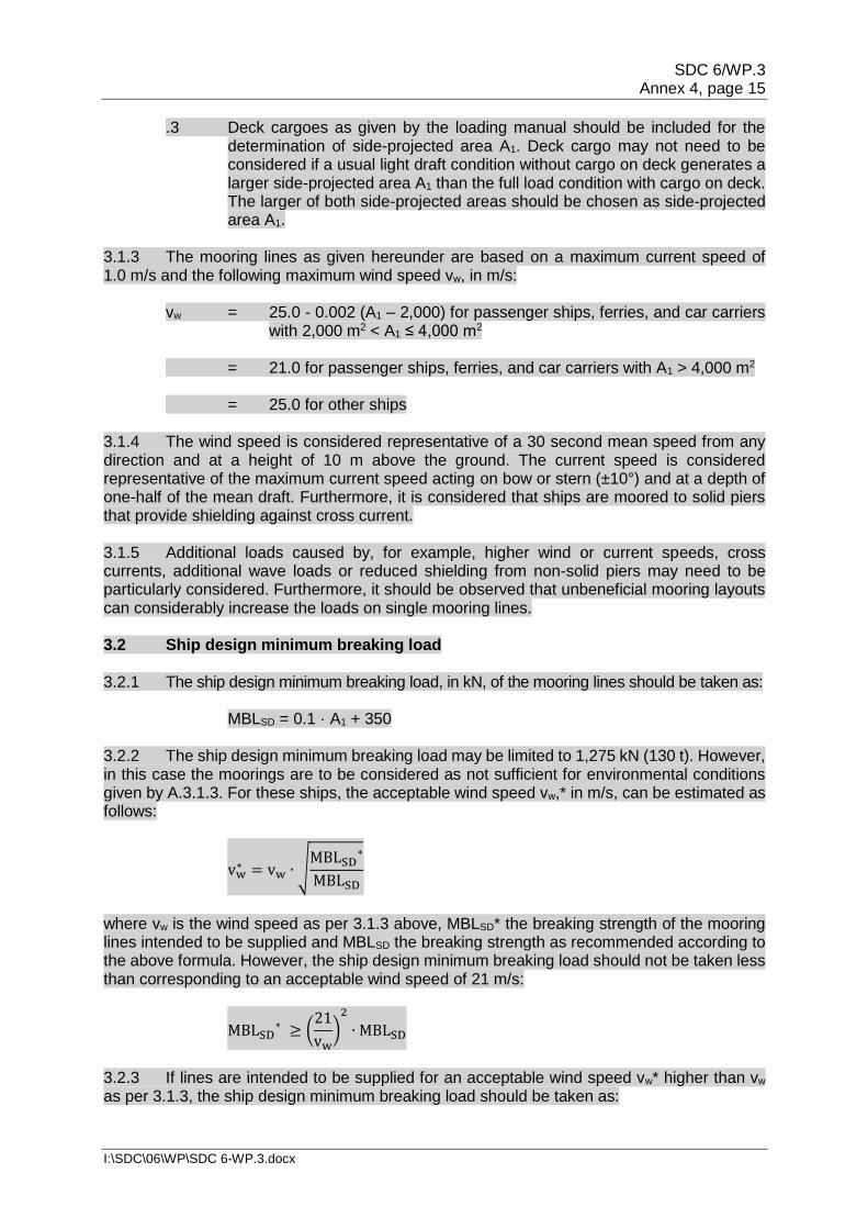
SDC 6/WP.3 Annex 4, page 15
I:\SDC\06\WP\SDC 6-WP.3.docx
.3 Deck cargoes as given by the loading manual should be included for the determination of side-projected area A1. Deck cargo may not need to be considered if a usual light draft condition without cargo on deck generates a larger side-projected area A1 than the full load condition with cargo on deck. The larger of both side-projected areas should be chosen as side-projected area A1.
3.1.3 The mooring lines as given hereunder are based on a maximum current speed of 1.0 m/s and the following maximum wind speed vw, in m/s:
vw = 25.0 - 0.002 (A1 – 2,000) for passenger ships, ferries, and car carriers with 2,000 m2 < A1 ≤ 4,000 m2
= 21.0 for passenger ships, ferries, and car carriers with A1 > 4,000 m2 = 25.0 for other ships
3.1.4 The wind speed is considered representative of a 30 second mean speed from any direction and at a height of 10 m above the ground. The current speed is considered representative of the maximum current speed acting on bow or stern (±10°) and at a depth of one-half of the mean draft. Furthermore, it is considered that ships are moored to solid piers that provide shielding against cross current. 3.1.5 Additional loads caused by, for example, higher wind or current speeds, cross currents, additional wave loads or reduced shielding from non-solid piers may need to be particularly considered. Furthermore, it should be observed that unbeneficial mooring layouts can considerably increase the loads on single mooring lines. 3.2 Ship design minimum breaking load 3.2.1 The ship design minimum breaking load, in kN, of the mooring lines should be taken as:
MBLSD = 0.1 · A1 + 350 3.2.2 The ship design minimum breaking load may be limited to 1,275 kN (130 t). However, in this case the moorings are to be considered as not sufficient for environmental conditions given by A.3.1.3. For these ships, the acceptable wind speed vw,* in m/s, can be estimated as follows:
vw∗ = vw ∙ √
MBLSD∗
MBLSD
where vw is the wind speed as per 3.1.3 above, MBLSD* the breaking strength of the mooring lines intended to be supplied and MBLSD the breaking strength as recommended according to the above formula. However, the ship design minimum breaking load should not be taken less than corresponding to an acceptable wind speed of 21 m/s:
MBLSD∗ ≥ (
21
vw)
2
∙ MBLSD
3.2.3 If lines are intended to be supplied for an acceptable wind speed vw* higher than vw as per 3.1.3, the ship design minimum breaking load should be taken as:
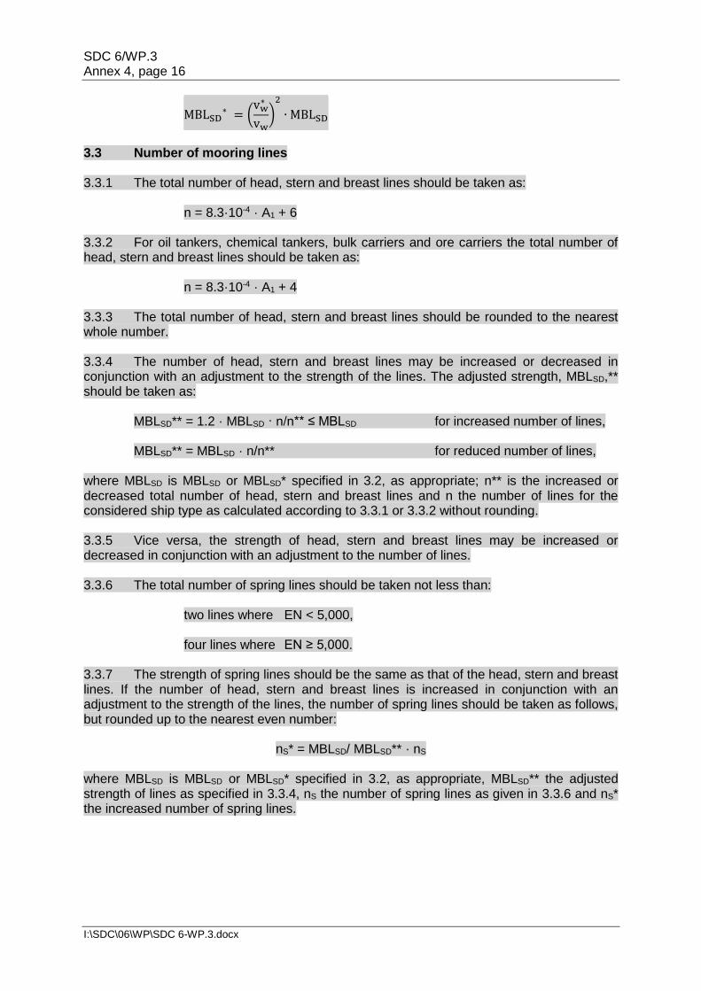
SDC 6/WP.3 Annex 4, page 16
I:\SDC\06\WP\SDC 6-WP.3.docx
MBLSD∗ = (
vw∗
vw)
2
∙ MBLSD
3.3 Number of mooring lines 3.3.1 The total number of head, stern and breast lines should be taken as:
n = 8.3·10-4 · A1 + 6 3.3.2 For oil tankers, chemical tankers, bulk carriers and ore carriers the total number of head, stern and breast lines should be taken as:
n = 8.3·10-4 · A1 + 4 3.3.3 The total number of head, stern and breast lines should be rounded to the nearest whole number. 3.3.4 The number of head, stern and breast lines may be increased or decreased in conjunction with an adjustment to the strength of the lines. The adjusted strength, MBLSD,** should be taken as:
MBLSD** = 1.2 · MBLSD · n/n** ≤ MBLSD for increased number of lines,
MBLSD** = MBLSD · n/n** for reduced number of lines, where MBLSD is MBLSD or MBLSD* specified in 3.2, as appropriate; n** is the increased or decreased total number of head, stern and breast lines and n the number of lines for the considered ship type as calculated according to 3.3.1 or 3.3.2 without rounding. 3.3.5 Vice versa, the strength of head, stern and breast lines may be increased or decreased in conjunction with an adjustment to the number of lines. 3.3.6 The total number of spring lines should be taken not less than:
two lines where EN < 5,000, four lines where EN ≥ 5,000.
3.3.7 The strength of spring lines should be the same as that of the head, stern and breast lines. If the number of head, stern and breast lines is increased in conjunction with an adjustment to the strength of the lines, the number of spring lines should be taken as follows, but rounded up to the nearest even number:
nS* = MBLSD/ MBLSD** · nS
where MBLSD is MBLSD or MBLSD* specified in 3.2, as appropriate, MBLSD** the adjusted strength of lines as specified in 3.3.4, nS the number of spring lines as given in 3.3.6 and nS* the increased number of spring lines.
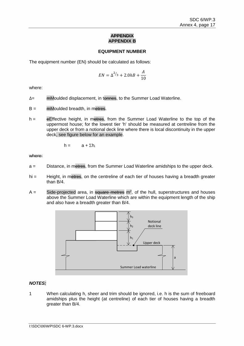
SDC 6/WP.3 Annex 4, page 17
I:\SDC\06\WP\SDC 6-WP.3.docx
APPENDIX APPENDIX B
EQUIPMENT NUMBER
The equipment number (EN) should be calculated as follows:
𝐸𝑁 = ∆2
3⁄ + 2.0ℎ𝐵 +𝐴
10
where: ∆= mMoulded displacement, in tonnes, to the Summer Load Waterline. B = mMoulded breadth, in metres. h = eEffective height, in metres, from the Summer Load Waterline to the top of the
uppermost house; for the lowest tier 'h' should be measured at centreline from the upper deck or from a notional deck line where there is local discontinuity in the upper deck, see figure below for an example.
h = a + hi where: a = Distance, in metres, from the Summer Load Waterline amidships to the upper deck. hi = Height, in metres, on the centreline of each tier of houses having a breadth greater
than B/4. A = Side-projected area, in square metres m2, of the hull, superstructures and houses
above the Summer Load Waterline which are within the equipment length of the ship and also have a breadth greater than B/4.
NOTES: 1 When calculating h, sheer and trim should be ignored, i.e. h is the sum of freeboard
amidships plus the height (at centreline) of each tier of houses having a breadth greater than B/4.
Summer Load waterline
a
h1
h2
h3
Notional deck line
Upper deck
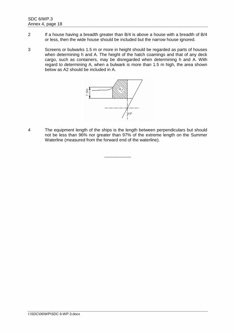
SDC 6/WP.3 Annex 4, page 18
I:\SDC\06\WP\SDC 6-WP.3.docx
2 If a house having a breadth greater than B/4 is above a house with a breadth of B/4 or less, then the wide house should be included but the narrow house ignored.
3 Screens or bulwarks 1.5 m or more in height should be regarded as parts of houses
when determining h and A. The height of the hatch coamings and that of any deck cargo, such as containers, may be disregarded when determining h and A. With regard to determining A, when a bulwark is more than 1.5 m high, the area shown below as A2 should be included in A.
4 The equipment length of the ships is the length between perpendiculars but should
not be less than 96% nor greater than 97% of the extreme length on the Summer Waterline (measured from the forward end of the waterline).
___________

![Draft Commission Regulation - SERA Part B Commission Regulation... · Draft . COMMISSION REGULATION (EU) No …/… of […] ... “‘aircraft observation’ means the evaluation](https://img.pdfslide.net/doc/110x75/5ac3ebc17f8b9af91c8c911f/draft-commission-regulation-sera-part-b-commission-regulationdraft-commission.jpg)


![ANNEX DRAFT IRIDIUM GLOBAL SATELLITE EGC ......ANNEX DRAFT IRIDIUM GLOBAL SATELLITE EGC SYSTEM MANUAL [2019][2020] EDITION Foreword SOLAS regulation IV/12.2 states that "Every ship,](https://img.pdfslide.net/doc/110x75/5e67e4684c1eca5ff1385d15/annex-draft-iridium-global-satellite-egc-annex-draft-iridium-global-satellite.jpg)